

Page 1
Industrial PC Platform
NY-series
IPC Machine Controller
Industrial Box PC
Hardware User's Manual
NY512-1500-1XX£13££X
NY512-1400-1XX£13££X
NY512-1300-1XX£13££X
Industrial Box PC
W556-E2-04
Page 2

NOTE
All rights reserved. No part of this publication may be reproduced, stored in a retrieval system, or
transmitted, in any form, or by any means, mechanical, electronic, photocopying, recording, or other-
wise, without the prior written permission of OMRON.
No patent liability is assumed with respect to the use of the information contained herein. Moreover,
because OMRON is constantly striving to improve its high-quality products, the information contained
in this manual is subject to change without notice. Every precaution has been taken in the preparation
of this manual. Nevertheless, OMRON assumes no responsibility for errors or omissions. Neither is
any liability assumed for damages resulting from the use of the information contained in this publica-
tion.
Trademarks
• Sysmac and SYSMAC are trademarks or registered trademarks of OMRON Corporation in Japan
and other countries for OMRON factory automation products.
• Windows, Visual Basic and V
soft Corporation in the USA and other countries.
isual Studio are either registered trademarks or trademarks of Micro-
• EtherCAT® is registered trademark and patented technology, licensed by Beckhoff Automation
GmbH, Germany.
• ODVA, CIP, CompoNet, DeviceNet, and EtherNet/IP are trademarks of ODVA.
• The SD and SDHC logos are trademarks of SD-3C, LLC.
• Intel, the Intel Logo, Celeron and Intel Core are trademarks or registered trademarks of Intel Corpo-
ration or its subsidiaries in the USA and other countries.
Other company names and product names in this document are the trademarks or registered trade-
marks of their respective companies.
Copyrights
Microsoft product screen shots reprinted with permission from Microsoft Corporation.
Page 3

Introduction
Thank you for purchasing the IPC Machine Controller.
This manual contains information that is necessary to use the IPC Machine Controller. Please read
this manual and make sure you understand the functionality and performance of the Box PC before
attempting to use it in a control system.
Keep this manual in a safe place where it will be available for reference during operation.
Part of the specifications and restrictions for the IPC Machine Controller are available in other man-
uals.
Refer to Relevant Manuals on page 2 and Related Manuals on page 32.
Intended Audience
This manual is intended for the following personnel, who must also have knowledge of electrical sys-
tems (an electrical engineer or the equivalent).
• Personnel in charge of introducing Factory Automation systems.
• Personnel in charge of designing Factory Automation systems.
• Personnel in charge of installing and maintaining Factory Automation systems.
• Personnel in charge of managing Factory Automation systems and facilities.
For programming, this manual is intended for personnel who understand the programming language
specifications in international standard IEC 61131-3.
Introduction
Applicable Products
This manual covers following Industrial Box PC with Machine Automation Control Software configura-
tions:
NY512-1500-1XX£13££X
NY512-1400-1XX£13££X
NY512-1300-1XX£13££X
Additional Information
Refer to 1-4 Product Configuration on page
1 - 6 for configuration details.
NY-series Industrial Box PC Hardware User's Manual (W556)
1
Page 4

Relevant Manuals
Relevant Manuals
The following sections provide the relevant manuals for the IPC Machine Controller.
Read all of the manuals that are relevant to your system configuration and application before you use
the IPC Machine Controller.
Overview Relevant Manuals
Basic Information
Industrial Panel PC
Hardware User's Manual
Purpose of use
NY-series
IPC Machine Controller
NY-series
IPC Machine Controller
Industrial Box PC
Hardware User's Manual
IPC Machine Controller
Industrial Panel PC
Setup User's Manual
/ Industrial Box PC
Manual
NY-series
NY-series
IPC Machine Controller
Industrial Panel PC
Software User's Manual
/ Industrial Box PC
NY-series
Instructions Reference Manual
Motion Control User's Manual
NY-series
IPC Machine Controller
Industrial Panel PC
/ Industrial Box PC
NY-series Motion Control
Instructions Reference Manual
NY-series
IPC Machine Controller
Industrial Panel PC
Built-in EtherCAT Port User's Manual
/ Industrial Box PC
NY-series
IPC Machine Controller
Industrial Panel PC
Built-in EtherNet/IP Port User's Manual
/ Industrial Box PC
NY-series
T
roubleshooting Manual
Introduction to NY-series
Panel PC
Introduction to NY-series Box
PC
Setting devices and hardware
Using motion control
Using EtherCAT
Using EtherNet/IP
Making setup
Making initial settings
Preparing to use Controllers
Software settings
Using motion control
Using EtherCAT
Using EtherNet/IP
l
l l
l
l
l
l
l
l
l
l
l
2
NY-series Industrial Box PC Hardware User's Manual (W556)
Page 5

Basic Information
NY-series
IPC Machine Controller
Industrial Panel PC
Hardware User's Manual
NY-series
IPC Machine Controller
Industrial Box PC
Hardware User's Manual
Industrial Panel PC / Industrial Box PC
Setup User's Manual
Manual
NY-series
IPC Machine Controller
NY-series
IPC Machine Controller
Industrial Panel PC / Industrial Box PC
Software User's Manual
NY-series
Instructions Reference Manual
Motion Control User's Manual
Relevant Manuals
NY-series
IPC Machine Controller
Industrial Panel PC / Industrial Box PC
NY-series Motion Control
Instructions Reference Manual
NY-series
IPC Machine Controller
Industrial Panel PC / Industrial Box PC
Built-in EtherCA
NY-series
IPC Machine Controller
Industrial Panel PC / Industrial Box PC
Built-in EtherNet/IP Port User's Manual
NY-series
Troubleshooting Manul
Purpose of use
Writing the user program
Using motion control
Using EtherCAT
Using EtherNet/IP
Programming error processing
Testing operation and debugging
Using motion control
Using EtherCAT
Using EtherNet/IP
Learning about error man-
agement and corrections
Maintenance
Using motion control
Using EtherCAT
Using EtherNet/IP
*1. Refer to the NY
overview of the error items. Refer to the manuals that are indicated with triangles for details on errors for the
corresponding Units.
*1
-series Troubleshooting Manual (Cat. No. W564) for the error management concepts and an
p p p p p p l
l l
l
l l
l
l l
l
l
T Port User's Manual
l
l
l
l
l
l
l
NY-series Industrial Box PC Hardware User's Manual (W556)
3
Page 6

CONTENTS
CONTENTS
Introduction .............................................................................................................. 1
Intended Audience
Applicable Products ......................................................................................................................................... 1
Relevant Manuals..................................................................................................... 2
Overview Relevant Manuals ............................................................................................................................ 2
Manual Information.................................................................................................. 9
Page Structure.................................................................................................................................................9
Special Information ........................................................................................................................................ 10
Terms and Conditions Agreement........................................................................ 11
Warranty and Limitations of Liability .............................................................................................................. 11
Application Considerations ............................................................................................................................12
Disclaimers ....................................................................................................................................................12
...........................................................................................................................................1
Safety Precautions................................................................................................. 14
Definition of Precautionary Information.......................................................................................................... 14
Symbols ......................................................................................................................................................... 14
Warnings........................................................................................................................................................ 15
Cautions......................................................................................................................................................... 17
Precautions for Safe Use ...................................................................................... 18
Disassembly, Dropping, Mounting, Installation and Storage .........................................................................18
Wiring............................................................................................................................................................. 18
Power Supply Design and Turning ON/OFF the Power Supply.....................................................................18
Actual Operation ............................................................................................................................................ 19
Operation ....................................................................................................................................................... 19
General Communications ..............................................................................................................................20
EtherNet/IP Communications ........................................................................................................................20
EtherCAT Communications............................................................................................................................20
Motion Control ...............................................................................................................................................21
Restoring Data...............................................................................................................................................22
Battery Replacement .....................................................................................................................................22
Product Replacement ....................................................................................................................................23
Cleaning, Maintenance and Disposal ............................................................................................................23
Precautions for Correct Use ................................................................................. 24
Storage, Installation and Mounting ................................................................................................................24
Wiring............................................................................................................................................................. 24
Actual Operation and Operation ....................................................................................................................25
Error Processing ............................................................................................................................................ 25
Restoring Data...............................................................................................................................................26
Task Settings .................................................................................................................................................26
Motion Control ...............................................................................................................................................26
EtherCAT Communications............................................................................................................................26
Battery Replacement .....................................................................................................................................26
SD Memory Cards .........................................................................................................................................27
Regulations and Standards .................................................................................. 28
Conformance to EU Directives ......................................................................................................................28
Conformance to KC Standards......................................................................................................................29
Conformance to UL and CSA Standards.......................................................................................................29
Software Licenses and Copyrights ................................................................................................................29
Versions.................................................................................................................. 30
Check Unit Versions ......................................................................................................................................30
4
NY-series Industrial Box PC Hardware User's Manual (W556)
Page 7

CONTENTS
Check Hardware Revision .............................................................................................................................30
Related Manuals
Related IPC Machine Controller Manuals...................................................................................................... 32
Related Products Manuals............................................................................................................................. 34
..................................................................................................... 32
Terminology and Abbreviations ........................................................................... 35
Industrial PC Platform ...................................................................................................................................35
Hardware ......................................................................................................................................................35
Software......................................................................................................................................................... 36
Revision History..................................................................................................... 37
Sections in this Manual ......................................................................................... 39
Section 1 Introduction to the Industrial Box PC
1-1 Intended Use ........................................................................................................................1 - 2
1-2
Features ................................................................................................................................ 1 - 3
1-2-1 Hardware Features ...................................................................................................................1 - 3
1-2-2 Machine Controller Software Features......................................................................................1 - 4
1-3 ID Information Label ............................................................................................................1 - 5
1-3-1 Label with Controller License (Optional) ...................................................................................1 - 5
1-4 Product Configuration.........................................................................................................1 - 6
1-5 Overall Operating Procedure..............................................................................................1 - 7
Section 2 System Configurations
2-1 Basic Configurations...........................................................................................................2 - 2
2-2
EtherCAT Network Configuration.......................................................................................2 - 3
2-2-1 Related EtherCAT Hardware.....................................................................................................2 - 4
2-3 EtherNet/IP Network Configuration....................................................................................2 - 5
2-3-1 Related EtherNet/IP Hardware..................................................................................................2 - 5
2-4 Connection with the Sysmac Studio..................................................................................2 - 7
2-4-1 Configurations That Allow Online Connections.........................................................................2 - 7
2-4-2 Configurations That Do Not Allow Online Connections.............................................................2 - 8
Section 3 Hardware Overview
3-1 Component Names and Functions.....................................................................................3 - 3
3-1-1 Front and Top of the Industrial Box PC .....................................................................................3 - 3
3-1-2 Back of the Industrial Box PC ...................................................................................................3 - 6
3-2 LED Indicators......................................................................................................................3 - 7
3-2-1 PWR LED Indicator ...................................................................................................................3 - 7
3-2-2 ERR LED Indicator....................................................................................................................3 - 8
3-2-3 HDD LED Indicator....................................................................................................................3 - 8
3-2-4 RUN LED Indicator....................................................................................................................3 - 8
3-3 Power Button........................................................................................................................3 - 9
3-4 Drive Bays ..........................................................................................................................3 - 10
3-5 SD Memory Card Slot ........................................................................................................3 - 11
3-6 PCIe Card Slot....................................................................................................................3 - 12
NY-series Industrial Box PC Hardware User's Manual (W556)
5
Page 8

CONTENTS
3-7 Connectors.........................................................................................................................3 - 13
3-8 Spare Parts.........................................................................................................................3 - 18
3-9 Optional Hardware.............................................................................................................3 - 20
3-7-1
3-7-2 I/O Connector..........................................................................................................................3 - 13
3-7-3 USB Connectors .....................................................................................................................3 - 14
3-7-4 Ethernet Connectors ...............................................................................................................3 - 15
3-7-5 DVI Connector.........................................................................................................................3 - 15
3-7-6 RS-232C Connector (Optional) ...............................................................................................3 - 16
3-7-7 DVI-D Connector (Optional) ....................................................................................................3 - 16
3-7-8 NY Monitor Link Connector (Optional) ....................................................................................3 - 17
3-8-1 Battery.....................................................................................................................................3 - 18
3-8-2 Fan Unit...................................................................................................................................3 - 18
3-8-3 Accessory Kit ..........................................................................................................................3 - 19
3-9-1 Mounting Brackets ..................................................................................................................3 - 20
3-9-2 SD Memory Cards...................................................................................................................3 - 20
3-9-3 USB Flash Drives....................................................................................................................3 - 21
3-9-4 Storage Devices......................................................................................................................3 - 21
3-9-5 DVI Cables ..............................................................................................................................3 - 22
3-9-6 USB Type-A to USB Type-B Cables .......................................................................................3 - 22
3-9-7 NY Monitor Link Cables ..........................................................................................................3 - 23
3-9-8 Industrial Monitor ....................................................................................................................3 - 24
3-9-9 Power Supply ..........................................................................................................................3 - 24
3-9-10 UPS.........................................................................................................................................3 - 25
3-9-11 UPS Communication Cable ....................................................................................................3 - 25
Power Connector ....................................................................................................................3 - 13
Section 4 Specifications
4-1 General Specifications ....................................................................................................... 4 - 2
4-1-1
4-1-2 General Electrical Specifications...............................................................................................4 - 3
4-1-3 Power Consumption Specifications...........................................................................................4 - 3
4-1-4 CPU Specifications ...................................................................................................................4 - 4
4-1-5 Memory Specifications ..............................................................................................................4 - 4
4-1-6 Storage Device Specifications ..................................................................................................4 - 5
4-1-7 PCIe Card Specifications ..........................................................................................................4 - 7
4-1-8 Bracket Specifications...............................................................................................................4 - 8
4-2 Connector Specifications ...................................................................................................4 - 9
4-2-1 Power Connector Specifications ...............................................................................................4 - 9
4-2-2 I/O Connector Specifications...................................................................................................4 - 10
4-2-3 USB Connector Specifications ................................................................................................4 - 14
4-2-4 Ethernet Connector Specifications..........................................................................................4 - 15
4-2-5 DVI Connector Specifications .................................................................................................4 - 19
4-2-6 DVI-D Connector Specifications..............................................................................................4 - 20
4-2-7 RS-232C Connector Specifications.........................................................................................4 - 21
4-2-8 NY Monitor Link Connector Specifications..............................................................................4 - 21
4-3 Environmental Specifications...........................................................................................4 - 23
4-3-1 Operation Environment Specifications ....................................................................................4 - 23
4-3-2 Temperature and Humidity Specifications...............................................................................4 - 24
4-3-3 Recycling Specifications .........................................................................................................4 - 26
Dimensions and Weight ............................................................................................................4 - 2
Section 5 Installation
5-1 Unpack..................................................................................................................................5 - 2
5-1-1
5-1-2 Items Supplied ..........................................................................................................................5 - 3
5-2 Install Options......................................................................................................................5 - 5
5-2-1 Install a Drive ............................................................................................................................5 - 5
6
Unpack Procedure ....................................................................................................................5 - 2
NY-series Industrial Box PC Hardware User's Manual (W556)
Page 9

CONTENTS
5-2-2 Install the PCIe Card .................................................................................................................5 - 9
5-3
Mount ..................................................................................................................................5 - 14
5-3-1 Installation Method in Control Panels......................................................................................5 - 14
5-3-2 Product Orientation .................................................................................................................5 - 15
5-3-3 Temperature ............................................................................................................................5 - 15
5-3-4 Humidity ..................................................................................................................................5 - 18
5-3-5 Vibration and Shock ................................................................................................................5 - 18
5-3-6 Atmosphere.............................................................................................................................5 - 19
5-3-7 Electrical Environment ............................................................................................................5 - 19
5-3-8 Book Mount Procedure ...........................................................................................................5 - 24
5-3-9 Wall Mount Procedure.............................................................................................................5 - 25
5-4 Wire .....................................................................................................................................5 - 26
5-4-1 Wiring Warnings and Cautions................................................................................................5 - 26
5-4-2 Ground ....................................................................................................................................5 - 27
5-4-3 Wire the Power Connector ......................................................................................................5 - 34
5-4-4 Wire the I/O Connector ...........................................................................................................5 - 37
5-5 Connect...............................................................................................................................5 - 40
5-5-1 Connector Identification ..........................................................................................................5 - 41
5-5-2 Connection Procedure ............................................................................................................5 - 42
5-5-3 Ethernet Connection Procedure..............................................................................................5 - 44
5-5-4 Connect UPS ..........................................................................................................................5 - 45
5-6 Initial Power ON .................................................................................................................5 - 48
5-6-1 Initial Power ON Procedure.....................................................................................................5 - 48
Section 6 Operating Procedures
6-1 Power ON..............................................................................................................................6 - 2
6-1-1
6-1-2 Power ON Using the Power ON/OFF Input...............................................................................6 - 2
6-1-3 Power ON Using Safe Mode .....................................................................................................6 - 3
6-1-4 Auto Power ON .........................................................................................................................6 - 3
Power ON Using the Power Button...........................................................................................6 - 2
6-2 Power OFF............................................................................................................................6 - 4
6-2-1 Power OFF Using the Power Button .........................................................................................6 - 4
6-2-2 Power OFF Using the Power ON/OFF Input.............................................................................6 - 4
6-2-3 Forced Power OFF Using the Power Button.............................................................................6 - 5
Section 7 Maintenance
7-1 Preventive Maintenance......................................................................................................7 - 2
7-1-1
7-1-2 Clean the Box PC......................................................................................................................7 - 3
7-2 Corrective Maintenance ......................................................................................................7 - 4
7-2-1 Remove the Cover ....................................................................................................................7 - 4
7-2-2 Replace the Fan Unit ................................................................................................................7 - 5
7-2-3 Replace the Battery...................................................................................................................7 - 7
7-2-4 Replace a Drive.........................................................................................................................7 - 9
7-2-5 Replace the PCIe Card ...........................................................................................................7 - 14
Preventive Maintenance Schedule............................................................................................7 - 2
Appendices
A-1 BIOS ..................................................................................................................................... A - 2
A-1-1 BIOS Overview......................................................................................................................... A - 2
A-1-2 BIOS - Main.............................................................................................................................. A - 4
A-1-3 BIOS - Advanced ..................................................................................................................... A - 5
A-1-4 BIOS - Chipset ......................................................................................................................... A - 8
A-1-5 BIOS - Boot .............................................................................................................................. A - 9
NY-series Industrial Box PC Hardware User's Manual (W556)
7
Page 10

CONTENTS
A-2 Allocate a Drive in Windows ............................................................................................ A - 11
A-3 DVI Connector Pin Details................................................................................................ A - 12
A-4 RS-232C Connector Pin Details....................................................................................... A - 15
Index
A-1-6 BIOS - Security ...................................................................................................................... A - 10
A-1-7
A-3-1 DVI-I Connector Pin Details ................................................................................................... A - 12
A-3-2 DVI-D Connector Pin Details.................................................................................................. A - 13
BIOS - Save & Exit................................................................................................................. A - 10
8
NY-series Industrial Box PC Hardware User's Manual (W556)
Page 11
Manual Information
A
B
C
E
F
B
C
H
5 Installation
5 - 3
N
Y-series User's Manual (W555)
5-1 Unpack
5
5-1-1 Unpack Procedure
G
5-1
Unpack
This section provides details on how to unpack the Industrial Panel PC.
5-1-1
Unpack Procedure
1 Check the package for damage.
If there is any visible damage:
• Take photos of the package and save them.
• Inform your supplier immediately.
2 Open the package.
Ensure not to damage the contents.
3 Ensure that all items are present.
Additional Information
Refer to 5-1-2 Items Supplied with the Product
for the items supplied.
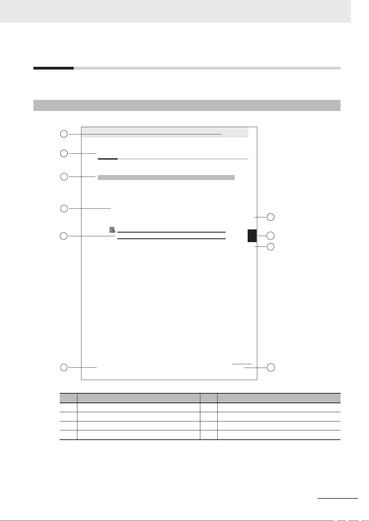
This section provides information about this manual.
Page Structure
The following page structure is used in this manual.
Manual Information
Note: This illustration is provided as a sample. It will not literally appear in this manual.
Item Explanation Item Explanation
A Level 1 heading E Special Information
B Level 2 heading F Manual name
C Level 3 heading G Page tab with the number of the main section
D Step in a procedure H Page number
NY-series Industrial Box PC Hardware User's Manual (W556)
9
Page 12

Manual Information
Special Information
Special information in this manual is classified as follows:
Precautions for Safe Use
Precautions on what to do and what not to do to ensure safe usage of the product.
Precautions for Correct Use
Precautions on what to do and what not to do to ensure proper operation and performance.
Additional Information
Additional information to read as required.
This information is provided to increase understanding or make operation easier
Version Information
.
Information on differences in specifications and functionality between different versions.
10
NY-series Industrial Box PC Hardware User's Manual (W556)
Page 13

Terms and Conditions Agreement
Terms and Conditions Agreement
Warranty and Limitations of Liability
Warranty
• Exclusive Warranty
Omron’s exclusive warranty is that the Products will be free from defects in materials and workman-
ship for a period of twelve months from the date of sale by Omron (or such other period expressed
in writing by Omron). Omron disclaims all other warranties, expressed or implied.
• Limitations
OMRON MAKES NO WARRANTY OR REPRESENTATION, EXPRESS OR IMPLIED, ABOUT
NON-INFRINGEMENT, MERCHANTABILITY OR FITNESS FOR A PARTICULAR PURPOSE OF
THE PRODUCTS. BUYER ACKNOWLEDGES THAT IT ALONE HAS DETERMINED THAT THE
PRODUCTS WILL SUITABLY MEET THE REQUIREMENTS OF THEIR INTENDED USE.
Omron further disclaims all warranties and responsibility of any type for claims or expenses based
on infringement by the Products or otherwise of any intellectual property right.
• Buyer Remedy
Omron’s sole obligation hereunder shall be, at Omron’s election, to (i) replace (in the form originally
shipped with Buyer responsible for labor charges for removal or replacement thereof) the non-com-
plying Product, (ii) repair the non-complying Product, or (iii) repay or credit Buyer an amount equal
to the purchase price of the non-complying Product; provided that in no event shall Omron be re-
sponsible for warranty, repair, indemnity or any other claims or expenses regarding the Products un-
less Omron’s analysis confirms that the Products were properly handled, stored, installed and main-
tained and not subject to contamination, abuse, misuse or inappropriate modification. Return of any
Products by Buyer must be approved in writing by Omron before shipment. Omron Companies shall
not be liable for the suitability or unsuitability or the results from the use of Products in combination
with any electrical or electronic components, circuits, system assemblies or any other materials or
substances or environments. Any advice, recommendations or information given orally or in writing,
are not to be construed as an amendment or addition to the above warranty.
See http://www.omron.com/global/ or contact your Omron representative for published information.
Limitations of Liability
OMRON COMPANIES SHALL NOT BE LIABLE FOR SPECIAL, INDIRECT, INCIDENTAL, OR CON-
SEQUENTIAL DAMAGES, LOSS OF PROFITS OR PRODUCTION OR COMMERCIAL LOSS IN ANY
WAY CONNECTED WITH THE PRODUCTS, WHETHER SUCH CLAIM IS BASED IN CONTRACT,
WARRANTY, NEGLIGENCE OR STRICT LIABILITY. Further, in no event shall liability of Omron Com-
panies exceed the individual price of the Product on which liability is asserted.
NY-series Industrial Box PC Hardware User's Manual (W556)
11
Page 14

Terms and Conditions Agreement
Application Considerations
Suitability for Use
Omron Companies shall not be responsible for conformity with any standards, codes or regulations
which apply to the combination of the Product in the Buyer
er’s request, Omron will provide applicable third party certification documents identifying ratings and
limitations of use which apply to the Product. This information by itself is not sufficient for a complete
determination of the suitability of the Product in combination with the end product, machine, system, or
other application or use. Buyer shall be solely responsible for determining appropriateness of the par-
ticular Product with respect to Buyer’s application, product or system. Buyer shall take application re-
sponsibility in all cases.
NEVER USE THE PRODUCT FOR AN APPLICATION INVOLVING SERIOUS RISK TO LIFE OR
PROPERTY WITHOUT ENSURING THAT THE SYSTEM AS A WHOLE HAS BEEN DESIGNED TO
ADDRESS THE RISKS, AND THAT THE OMRON PRODUCT(S) IS PROPERLY RATED AND IN-
STALLED FOR THE INTENDED USE WITHIN THE OVERALL EQUIPMENT OR SYSTEM.
’s application or use of the Product. At Buy-
Programmable Products
• Omron Companies shall not be responsible for the user’s programming of a programmable Product,
or any consequence thereof.
•
Omron Companies shall not be responsible for the operation of the user accessible operating sys-
tem (e.g. Windows, Linux), or any consequence thereof.
Disclaimers
Performance Data
Data presented in Omron Company websites, catalogs and other materials is provided as a guide for
the user in determining suitability and does not constitute a warranty
Omron’s test conditions, and the user must correlate it to actual application requirements. Actual per-
formance is subject to the Omron’s Warranty and Limitations of Liability.
Change in Specifications
. It may represent the result of
12
Product specifications and accessories may be changed at any time based on improvements and oth-
er reasons. It is our practice to change part numbers when published ratings or features are changed,
or when significant construction changes are made. However
be changed without any notice. When in doubt, special part numbers may be assigned to fix or estab-
lish key specifications for your application. Please consult with your Omron’s representative at any
time to confirm actual specifications of purchased Product.
NY-series Industrial Box PC Hardware User's Manual (W556)
, some specifications of the Product may
Page 15

Terms and Conditions Agreement
Errors and Omissions
Information presented by Omron Companies has been checked and is believed to be accurate; how-
ever
, no responsibility is assumed for clerical, typographical or proofreading errors or omissions.
NY-series Industrial Box PC Hardware User's Manual (W556)
13
Page 16
Safety Precautions
Safety Precautions
Definition of Precautionary Information
The following notation is used in this manual to provide precautions required to ensure safe usage of
the IPC Machine Controller. The safety precautions that are provided are extremely important to safe-
ty.
Always read and heed the information provided in all safety precautions.
The following notation is used.
Indicates a potentially hazardous situation which, if not avoid-
WARNING
Caution
ed, could result in death or serious injury
may be severe property damage.
Indicates a potentially hazardous situation which, if not avoid-
ed, may result in minor or moderate injury
. Additionally, there
, or property damage.
Symbols
The circle and slash symbol indicates operations that you must not do. The
specific operation is shown in the circle and explained in text.
This example indicates prohibiting disassembly
The triangle symbol indicates precautions (including warnings). The specific
operation is shown in the triangle and explained in text.
This example indicates a precaution for electric shock.
The triangle symbol indicates precautions (including warnings). The specific
operation is shown in the triangle and explained in text.
This example indicates a general precaution.
The filled circle symbol indicates operations that you must do. The specific
operation is shown in the circle and explained in text.
This example shows a general precaution for something that you must do.
.
14
NY-series Industrial Box PC Hardware User's Manual (W556)
Page 17

Warnings
Disassembly and Dropping
Do not attempt to disassemble, repair, or modify the product in any way. Doing so may result in malfunction or fire.
Installation
Always connect to a ground of 100 Ω or less when installing the product.
Safety Precautions
WARNING
Ensure that installation and post-installation checks of the product are performed by personnel in charge who possess a thorough understanding of
the machinery to be installed.
Fail-safe Measures
Provide safety measures in external circuits to ensure safety in the system if
an abnormality occurs due to malfunction of the product or due to other external factors af
dents due to incorrect operation.
Emergency stop circuits, interlock circuit, limit circuits, and similar safety
measures must be provided in external control circuits.
The product will turn OFF all outputs from Output Units in the following cases. The slaves will operate according to the settings in the slaves.
• If an error occurs in the power supply
• If a CPU watchdog timer error or CPU reset occurs
• If a major fault level Controller error occurs
• While the product is on standby until RUN mode is entered after the pow-
er is turned ON
• If a system initialization error occurs
External safety measures must be provided to ensure safe operation of the
system in such cases.
If external power supplies for slaves or other devices are overloaded or
short-circuited, the voltage will drop, outputs will turn OFF
may be unable to read inputs. Provide external safety measures in controls
with monitoring of external power supply voltage as required so that the system operates safely in such a case.
Unintended behavior may occur when an error occurs in internal memory of
the product. As a countermeasure for such problems, external safety measures must be provided to ensure safe operation of the system.
fecting operation. Not doing so may result in serious acci-
, and the system
NY-series Industrial Box PC Hardware User's Manual (W556)
15
Page 18

Safety Precautions
Provide measures in the communications system and user program to ensure safety in the overall system even if errors or malfunctions occur in data
link communications or remote I/O communications.
If there is interference in remote I/O communications or if a major fault level
error occurs, output status will depend on the products that are used. Confirm the operation that will occur when there is interference in communications or a major fault level error
of the settings in the slaves and Units.
The use of an uninterruptible power supply (UPS) allows normal operation
to continue even if a momentary power failure occurs, possibly resulting in
the reception of an erroneous signal from an external device affected by the
momentary power failure. Take external fail-safe measures. Where necessary, monitor the power supply voltage on the system for external devices
and use it as an interlock condition.
Downloading
, and implement safety measures. Adjust all
Always confirm safety at the destination before you transfer a user program,
configuration data, setup data, or device variables from the Sysmac Studio.
The devices or machines may perform unexpected operation regardless of
the operating mode of the product.
Actual Operation
Check the user program, data, and parameter settings for proper execution
before you use them for actual operation.
Security setting adjustments should only be performed by the engineer in
charge that possesses a thorough understanding of the security settings.
Selecting non-recommended security settings can put your system at risk.
Changing BIOS information is only allowed for the engineer in charge that
possesses a thorough understanding of the BIOS settings because it can
change the behavior of the product.
16
NY-series Industrial Box PC Hardware User's Manual (W556)
Page 19
Cautions
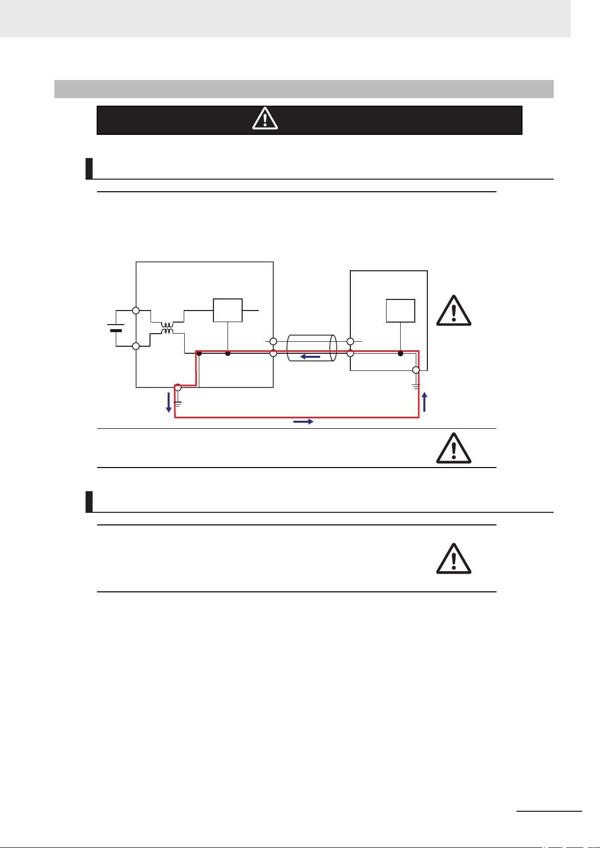
Industrial PC Platform Product
Non-isolated
Device
Non-isolated
Interface
24 VDC
0 VDC
Wiring
The product has an internal non-isolated DC power supply. Circuit ground (0
VDC) and frame ground are connected together. When connecting a nonisolated device or a non-isolated interface to the product, take appropriate
actions to avoid communication failures or damage to the mentioned ports.
Safety Precautions
Caution
Never ground the 24 VDC side of the power supply. This may cause a short
circuit.
Online Editing
Execute online editing only after confirming that no adverse effects will be
caused by deviations in the timing of I/O. If you perform online editing, the
task execution time may exceed the task period, I/O may not be refreshed
with external devices, input signals may not be read, and output timing may
change.
NY-series Industrial Box PC Hardware User's Manual (W556)
17
Page 20

Precautions for Safe Use
Precautions for Safe Use
Disassembly, Dropping, Mounting, Installation and Storage
• Do not drop the product or subject it to abnormal vibration or shock. Doing so may result in product
malfunction or burning.
• When unpacking, check carefully for any external scratches or other damages. Also, shake the
product gently and check for any abnormal sound.
• Always use the devices specified in the relevant manual.
• The product must be installed in a control panel.
• Always install equipment that is included in the product specifications. Not doing so may result in
failure or malfunction.
• If the storage period exceeds 6 months, check the performance of the Fan Unit before production
starts.
• Install the product in the correct orientation and temperature according to the specifications in the
manual to prevent overheating. Not doing so may result in malfunction.
• When connecting peripheral devices to the product, ensure sufficient countermeasures against
noise and static electricity during installation of the peripheral devices.
Wiring
• Follow the instructions in the manual to correctly perform connector wiring and insertion. Double-
• Always ensure connectors, cables, PCIe Cards and Storage devices are completely locked in place
• Before you connect a computer to the product, disconnect the power supply plug of the computer
• Do not bend or pull the cables beyond normal limit. Do not place heavy objects on top of the cables
• Always use power supply wires with sufficient wire diameters to prevent voltage drop and burning.
• Be sure that all mounting bracket screws and cable connector screws are tightened to the torque
• Use crimp terminals for wiring.
• For an NY Monitor Link connection, always follow the cable type and connection method specifica-
check all wiring and connector insertion before turning ON the power supply.
to prevent accidental disconnection.
from the AC outlet. Also, if the computer has an FG terminal, make the connections so that the FG
terminal has the same electrical potential as the product. A difference in electrical potential between
the computer and the product may cause failure or malfunction.
or other wiring lines. Doing so may break the cables.
Make sure that the current capacity of the wire is sufficient. Otherwise, excessive heat may be gen-
erated. When cross-wiring terminals, the total current for all the terminals will flow in the wire. When
wiring cross-overs, make sure that the current capacity of each of the wires is not exceeded.
specified in the relevant manuals. The loose screws may result in fire or malfunction.
tions in the manual. Otherwise, communications may be faulty.
Power Supply Design and Turning ON/OFF the Power Supply
• Always use a power supply that provides power within the rated range in the manual.
• Do not perform a dielectric strength test.
18
NY-series Industrial Box PC Hardware User's Manual (W556)
Page 21

Precautions for Safe Use
• Always use the recommended uninterruptable power supply (UPS) to prevent data loss and other
system file integrity issues caused by unexpected power interruption. Back up the system files in the
planned way to prevent data loss and other system file integrity issues caused by incorrect opera-
tion.
•
Use an Omron S8BA UPS with the correct revision number to prevent improper system shutdown.
• It takes up to approximately 10 to 20 s to enter RUN mode after the power is turned ON. The out-
puts during this time behave according to the slave or Output Unit specifications. Implement fail-safe
circuits so that external devices do not operate incorrectly.
• Power ON after the DVI or NY Monitor Link cable is connected between the product and an external
monitor.
• Always check the power supply and power connections before applying power. Incorrect power con-
nections can damage the product or cause burning.
• Always turn OFF the power supply to system before you attempt any of the following.
• Inserting or removing PCIe Cards
• Connecting cables
• Connecting or disconnecting the connectors
• Wiring the system
• Replacing or removing the HDD/SSD
• Replacing the Battery
• Replacing the Fan Unit
Actual Operation
• Choose a OS password that is not obvious to prevent unauthorized access.
Remember the OS user name and password. The product is inaccessible without it.
•
• Before operating the system , please make sure the appropriate software is installed and config-
ured. Doing so may prevent unexpected operation.
• Install all updates and ensure the browser stays up-to-date.
• Install all updates and ensure the firewall stays up-to-date.
• Make sure that your OS environment is protected against malicious software and viruses.
• Install all updates and ensure virus definitions stay up-to-date.
• Do not remove the fan cover while the power is ON. Contact with a rotating fan may result in injury.
• Virtual memory settings can affect the performance of the system. Disable the paging file after in-
stallation of applications or updates.
• Correctly perform wiring and setting, and ensure that the shutdown by the UPS can be executed.
Operation
• Confirm that no adverse effect will occur in the system before you attempt any of following.
Changing the operating mode of the product (including changing the setting of the Startup Mode)
•
• Changing the user program or settings
• Changing set values or present values
• Forced refreshing
• Do not carry out the following operations when accessing a USB device or an SD Memory Card.
• Turn OFF the power supply of the product.
• Press the Power Button of the product.
• Remove a USB device or SD memory card.
NY-series Industrial Box PC Hardware User's Manual (W556)
19
Page 22

Precautions for Safe Use
• If two different function modules are used together, such as when you see PCIe connected board
and EtherCA
that safety is maintained in the controlled system if one of the function modules stops. The relevant
outputs will behave according to the slave or Output Unit specifications if a partial fault level error
occurs in one of the function modules.
• Do not attempt to remove or touch the fan unit while the product is powered ON or immediately after
the power supply is turned OFF. If you attempt to replace the fan unit then, there is a risk of personal
injury due to hot or rotating parts.
• Press the power button for several seconds to force the product shutdown. Always back up files in
the planned way to prevent data loss or system file corruption.
• Do not touch any product housing when power is being supplied or immediately after the power sup-
ply is turned OFF. Doing so may result in burn injury.
• Always confirm safety at the connected equipment before you perform the following operations
when the device output hold configuration is set to enable. The equipment may operate unexpected-
ly because the last status for outputs is retained.
• Changing the operating mode of the product
• When downloaded
T slaves, take suitable measures in the user program and external controls to ensure
General Communications
• Unexpected operation may result if inappropriate data link tables are set. Even if appropriate data
link tables have been set, confirm that the controlled system will not be adversely af
you transfer the data link tables. The data links start automatically after the data link tables are
transferred.
• Separate the machine network segment from the office network to avoid communication failures.
EtherNet/IP Communications
• Make sure that the communications distance, number of nodes connected, and method of connec-
tion for EtherNet/IP are within specifications. Do not connect EtherNet/IP communications to Ether-
T or other networks. An overload may cause the network to fail or malfunction.
CA
• All related EtherNet/IP nodes are reset when you transfer settings for the built-in EtherNet/IP port
(including IP addresses and tag data links settings). The settings can only be enabled after the re-
set. Confirm that the system will not be adversely affected by resetting nodes before you transfer the
settings.
• If EtherNet/IP tag data links (cyclic communications) are used with a repeating hub, the communica-
tions load on the network will increase. This will increase collisions and may prevent stable commu-
nications. Do not use repeating hubs on networks where tag data links are used. Use an Ethernet
switch instead.
fected before
EtherCAT Communications
• Malfunctions or unexpected operation may occur for some combinations of EtherCAT revisions of
the master and slaves. If you disable the revision check in the network settings, use the Sysmac
Studio to check the slave revision settings in the master and the actual slave revisions, and then
make sure that functionality is compatible in the slave manuals or other references. Y
the actual slave revisions from the Sysmac Studio or on slave nameplates.
20
ou can check
NY-series Industrial Box PC Hardware User's Manual (W556)
Page 23

Precautions for Safe Use
• If the Fail-soft Operation parameter is set to stop operation, process data communications will stop
for all slaves when an EtherCA
Drive will operate according to the Servo Drive specifications. Make sure that the Fail-soft Operation
parameter setting results in safe operation when a device error occurs.
• If noise occurs or an EtherCAT slave is disconnected from the network, any current communications
frames may be lost. If frames are lost, slave I/O data is not communicated, and unintended opera-
tion may occur. The slave outputs will behave according to the slave specifications. Refer to the
manual for the slave. If a noise countermeasure or slave replacement is required, perform the fol-
lowing processing.
• Program the Input Data Invalid system-defined variable as an interlock condition in the user pro-
gram.
• Set the PDO communications timeout detection count setting in the EtherCAT master to at least 2.
Refer to the NY-series IPC Machine Controller Industrial Panel PC / Industrial Box PC Built-in
EtherCAT Port User’s Manual (Cat. No. W562) for details.
• EtherCAT communications are not always established immediately after the power supply is turned
ON. Use the system-defined variables in the user program to confirm that communications are es-
tablished before attempting control operations.
• When an EtherCAT slave is disconnected or disabled, communications will stop and control of the
outputs will be lost not only for the disconnected slave, but for all slaves connected after it. Confirm
that the system will not be adversely affected before you disconnect or disable a slave.
• You cannot use standard Ethernet hubs or repeater hubs with EtherCAT communications. If you use
one of these, a major fault level error or other error may occur.
• Always use the specified EtherCAT slave cables. If you use any other cable, the EtherCAT master
or the EtherCAT slaves may detect an error and one of the following may occur.
• Continuous refreshing of process data communications will not be possible.
• Continuous refreshing of process data communications will not end during the set cycle.
T communications error is detected in a slave. At that time, the Servo
Motion Control
• The motor is stopped if communications are interrupted between the Sysmac Studio and the product
during an MC T
curely and confirm that the system will not be adversely affected before you perform an MC Test
Run.
• The positive drive prohibit input (POT), negative drive prohibit input (NOT), and home proximity in-
put (DEC) of the Servo Drive are used by the MC Function Module as the positive limit input, nega-
tive limit input, and home proximity input. Make sure that the signal widths for all of these input sig-
nals are longer than the control period of the MC Function Module. If the input signal widths are
shorter than the control period, the MC Function Module may not be able to detect the input signals,
resulting in incorrect operation.
• Always execute the Save Cam Table instruction if you change any of the cam data from the user
program in the CPU Unit or from the Sysmac Studio. If the cam data is not saved, the previous con-
dition will be restored when the power is turned ON again, possibly causing unexpected machine
operation.
• Confirm the axis number carefully before you perform an MC Test Run.
• Use the NX_AryDOutTimeStamp (Write Digital Output Array with Specified Time Stamp) instruction
only after you confirm that InOperation from the MC_DigitalCamSwitch (Enable Digital Cam Switch)
instruction is TRUE.
est Run. Connect the communications cable between the computer and product se-
NY-series Industrial Box PC Hardware User's Manual (W556)
21
Page 24

FirstOnPosition LastOnPosition
OnCompensation
FirstOnPosition
after compensation
FirstOnPosition LastOnPosition
OffCompensation
LastOnPosition
after compensation
Precautions for Safe Use
• Always use the axis at a constant velocity for the MC_DigitalCamSwitch (Enable Digital Cam
Switch) instruction.
If you set the Count Mode to Rotary Mode, the following operation will occur if you use OnCompen-
sation
• If the value of OnCompensation or OffCompensation is equivalent to the time for half a rotation or
• If the value of OnCompensation results in exceeding LastOnPosition, the output timing will be un-
• If the value of OffCompensation results in exceeding FirstOnPosition, the output timing will be un-
or OffCompensation and the axis velocity changes abruptly.
more, InOperation will be FALSE.
stable.
stable.
Restoring Data
• The absolute encoder home offsets are backed up with a non-volatile memory in the product as ab-
solute encoder information. If any of the following conditions is met, clear the absolute encoder
home of
fsets from the list of data items to restore, and then restore the data. Then, define the abso-
lute encoder home again. If you do not define home, unintended operation of the controlled system
may occur.
• The Servomotor or Servo Drive was changed since the data was backed up.
• The absolute encoder was set up after the data was backed up.
• The absolute data for the absolute encoder was lost.
• You can partially or cannot at all back up, restore, or compare data of the settings depending on
slaves and Units. Also, you cannot back up, restore, or compare data for disabled slaves or Units.
After you restore data, sufficiently confirm that operation is correct before you start actual operation.
Battery Replacement
• Dispose of any Battery that has been dropped on the floor or otherwise subjected to excessive
shock. Batteries that have been subjected to shock may leak if they are used.
UL standards require that only an experienced engineer replace the Battery. Make sure that an ex-
•
perienced engineer is in charge of Battery replacement.
• The Battery may leak, rupture, heat, or ignite. Never short-circuit, charge, disassemble, heat, or in-
cinerate the Battery or subject it to strong shock.
22
NY-series Industrial Box PC Hardware User's Manual (W556)
Page 25

Product Replacement
• Make sure that the required data, including the user program, configurations, settings and variables
is transferred to a product that was replaced and to externally connected devices before restarting
operation.
Be sure to include the tag data link settings and routing tables, which are stored in the product.
Cleaning, Maintenance and Disposal
• Do not use corrosive substances to clean the product. Doing so may result in the failure or malfunc-
tion.
Dispose of the product and batteries according to local ordinances as they apply.
•
• The following information must be displayed for all products that contain primary lithium batteries
with a perchlorate content of 6 ppb or higher when shipped to or transported through the State of
California, USA.
Perchlorate Material - special handling may apply
See http://www.dtsc.ca.gov/hazardouswaste/perchlorate.
• The product contains a lithium battery with a perchlorate content of 6ppb or higher. When exporting
an end product containing the product to or shipping through California, USA, label all packing and
shipping containers appropriately.
Precautions for Safe Use
.
NY-series Industrial Box PC Hardware User's Manual (W556)
23
Page 26

Precautions for Correct Use
Precautions for Correct Use
Storage, Installation and Mounting
• Do not operate or store the product in the following locations. Operation may stop or malfunctions
may occur.
• Locations subject to direct sunlight
• Locations subject to temperatures or humidity outside the range specified in the specifications
• Locations subject to condensation as the result of severe changes in temperature
• Locations subject to corrosive or flammable gases
• Locations subject to dust (especially iron dust) or salts
• Locations subject to exposure to water, oil or chemicals
• Locations subject to shock or vibration
• Locations outdoors subject to direct wind and rain
• Locations subject to strong ultraviolet light
• Always install the product with sufficient surrounding space to allow for adequate heat dissipation
and cooling effect.
• Take appropriate and sufficient countermeasures when installing the product in the following loca-
tions
• Locations subject to strong, high-frequency noise
• Locations subject to static electricity or other forms of noise
• Locations subject to strong electromagnetic fields
• Locations subject to possible exposure to radioactivity
• Locations close to power lines
• Always touch a grounded piece of metal to discharge static electricity from your body before starting
an installation or maintenance procedure.
• Insert USB devices and PCIe devices correctly to avoid the burning, failure or malfunction.
• Execute a backup of the product before PCIe addition or replacement. Be sure that the PCIe device
works correctly before you use them for actual operation. PCIe devices and their related software
may cause an OS boot failure or crash.
• Ensure the selected operating system supports ACPI to enable operating system shutdown using
the power button.
• Download the enhanced Video Driver from the OMRON Download Center and install it on the Indus-
trial PC.
Wiring
24
• Always ensure the rated supply voltage is connected to the product.
• Do not allow wire clippings, shavings, or other foreign material to enter the product. Otherwise, burn-
ing, failure, or malfunction may occur. Cover the product or take other suitable countermeasures, es-
pecially during wiring work.
• Do not use cables exceeding the maximum specified length. Doing so may cause malfunction.
• Do not connect an AC power supply to the DC power connector.
• Observe the following precautions to prevent broken wires.
• When you remove the sheath, be careful not to damage the conductor.
• Connect the conductor without twisting the wires.
NY-series Industrial Box PC Hardware User's Manual (W556)
Page 27

• Do not weld the conductors. Doing so may cause the wires to break with vibration.
Actual Operation and Operation
• After an OS update or a peripheral device driver update for the product is executed, the product be-
havior might be dif
• Ensure the fan is operational to provide adequate cooling while the power is turned ON.
• HDD and SSD storage devices, SD Memory Cards, power buttons, fan units and batteries have fi-
nite lives and if those are exceeded, the product may fail or malfunction.
• Always monitor the fan status. If a fan is used beyond its service life, the Low Revolution Speed
warning message is displayed and the product overheating may occur.
• Always monitor the battery warning message. When a battery has low voltage, the system time will
be lost.
• Do not reset or power OFF the product while the password is being changed. If you fail to save the
password there is a possibility that the project will not work.
• Always confirm safety at the connected equipment before you reset Controller errors with an event
level of partial fault or higher from the EtherCAT master Function Module. When the Error is reset,
all slaves that were in any state other than Operational state due to a Controller error with an event
level of partial fault or higher (in which output are disabled) will go to Operational state and the out-
puts will be enabled. Before you reset all errors or restart a slave, confirm that no Controller errors
with an event level of partial fault have occurred for the EtherCAT Master Function Module.
• The functions that are supported depend on the unit version of the product. The version of Sysmac
Studio that supports the functions that were added for an upgrade is also required to use those func-
tions. Refer to Version Information for NY-series Controllers for the relationship between the unit
versions of the controller and the Sysmac Studio versions, and for the functions that are supported
by each unit version.
• If the product experiences a sudden loss of power or disconnecting the cable while saving a setting
or transfer of data is underway, the changes may not be stored and unexpected behavior may occur.
• Ensure that available software checks are performed by personnel in charge who possess a thor-
ough understanding of the software.
• Always create a Rescue Disk using the Rescue Disk Utility and restore to recover the HDD/SSD
configuration if necessary.
• Confirm the device output hold configuration before you change the operating mode of the product
or execute the download.
ferent. Confirm that operation is correct before you start actual operation.
Precautions for Correct Use
Error Processing
• In applications that use the results of instructions that read the error status, consider the effect on
the system when errors are detected and program error processing accordingly
the detection of a minor error, such as Battery replacement during operation, can affect the system
depending on how the user program is written.
• If you change the event level of a Controller error, the output status when the error occurs may also
change. Confirm safety before you change an event level.
NY-series Industrial Box PC Hardware User's Manual (W556)
. For example, even
25
Page 28

Precautions for Correct Use
Restoring Data
• When you edit the restore command file, do not change anything in the file except for the “yes” and
“no” specifications for the selectable data groups. If you change anything else in the file, the Control-
ler may perform unexpected operation when you restore the data.
Task Settings
• If a Task Period Exceeded error occurs, shorten the programs to fit in the task period or increase the
setting of the task period.
Motion Control
• Before you start an MC Test Run, make sure that the operation parameters are set correctly.
Do not download motion control settings during an MC Test Run.
•
EtherCAT Communications
• Set the Servo Drives to stop operation if an error occurs in EtherCAT communications between the
Controller and a Servo Drive.
If you need to disconnect the cable from an EtherCAT slave during operation, first disconnect the
•
software connection to the EtherCAT slave or disable the EtherCAT slave and all of the EtherCAT
slaves that are connected after it.
• Make sure that all of the slaves to be restored are participating in the network before you reset a
Network Configuration Verification Error, Process Data Communications Error, or Link OFF Error in
the EtherCAT Master Function Module. If any slave is not participating when any of these errors is
reset, the EtherCAT Master Function Module may access slave with a different node address than
the specified node address or the error may not be reset correctly.
• Make sure that the communications distance, number of devices connected, and method of connec-
tion for EtherCAT are within specifications. Do not connect EtherCAT communications to
EtherNet/IP, a standard in-house LAN, or other networks. An overload may cause the network to fail
or malfunction.
• After you transfer the user program, the product is restarted and communications with the EtherCAT
slaves are cut off. During that period, the slave outputs behave according to the slave specifications.
The time that communications are cut off depends on the EtherCAT network configuration. Before
you transfer the user program, confirm that the system will not be adversely affected.
Battery Replacement
• Turn ON the power after replacing the battery for a product that has been unused for an extended
period of time. Leaving the product unused without turning ON the power even once after the battery
is replaced may result in a shorter battery life.
Make sure to use a battery of the correct type, install the battery properly.
•
• Apply power for at least five minutes before changing the battery. Mount a new battery within five
minutes after turning OFF the power supply. If power is not supplied for at least five minutes, the
clock data may be lost. Check the clock data after changing the battery.
26
NY-series Industrial Box PC Hardware User's Manual (W556)
Page 29

SD Memory Cards
• Insert an SD Memory Card completely and ensure it is in place.
Precautions for Correct Use
NY-series Industrial Box PC Hardware User's Manual (W556)
27
Page 30

Regulations and Standards
Regulations and Standards
Conformance to EU Directives
The IPC Machine Controller complies with EU Directives. To ensure that the machine or device in
which the IPC Machine Controller is used complies with EU Directives, the following precautions must
be observed:
• The IPC Machine Controller must be installed within a control panel.
• The IPC Machine Controller that complies with EU Directives also conforms to the Common Emis-
sion Standard. Radiated emission characteristics (10-m regulations) may vary depending on the
configuration of the control panel used, other devices connected to the control panel, wiring, and
other conditions. You must therefore confirm that the overall machine or equipment in which the IPC
Machine Controller is used complies with EU Directives.
• This is a Class A product (for industrial environments). In a residential environment, it may cause
radio interference. If radio interference occurs, the user may be required to take appropriate meas-
ures.
Applicable Directive
EMC Directive
EMC Directive
OMRON devices that comply with EU Directives also conform to the related EMC standards so that
they can be more easily built into other devices or the overall machine. The actual products have been
checked for conformity to EMC standards.
Applicable EMC (Electromagnetic Compatibility) standards are as follows:
• EMS (Electromagnetic Susceptibility): EN 61131-2
• EMI (Electromagnetic Interference): EN 61131-2 (Radiated emission: 10-m regulations)
Whether the products conform to the standards in the system used by the customer, however, must be
checked by the customer. EMC-related performance of the OMRON devices that comply with EU Di-
rectives will vary depending on the configuration, wiring, and other conditions of the equipment or con-
trol panel on which the OMRON devices are installed. The customer must, therefore, perform the final
check to confirm that devices and the overall machine conform to EMC standards.
28
NY-series Industrial Box PC Hardware User's Manual (W556)
Page 31

Conformance to KC Standards
Observe the following precaution if you use Industrial PC Platform products in Korea.
Class A Device (Broadcasting Communications Device for Office Use).
This device obtained EMC registration for of
other than homes.
Sellers and/or users need to take note of this.
fice use (Class A), and it is intended to be used in places
Conformance to UL and CSA Standards
Some Industrial PC Platform products comply with UL and CSA standards. If you use a product that
complies with UL or CSA standards and must apply those standards to your machinery or devices,
refer to this manual. This manual provides the application conditions for complying with the standards.
If the product is used in a manner not specified in the Instruction Sheet or in the product manuals then
the protection provided by the equipment may be impaired.
Regulations and Standards
Software Licenses and Copyrights
This product incorporates certain third party software. The license and copyright information associat-
ed with this software is available at http://www
.fa.omron.co.jp/nj_info_e/.
NY-series Industrial Box PC Hardware User's Manual (W556)
29
Page 32

Versions
Versions
Hardware revisions and unit versions are used to manage the hardware and software in NY-series
products. The hardware revision or unit version is updated each time there is a change in hardware or
software specifications. Even when two products have the same model number, they will have func-
tional or performance differences if they have different hardware revisions or unit versions.
Check Unit Versions
You can check unit versions on the ID Information Label or with the Sysmac Studio.
Check Unit Versions on ID Information Label
The unit version is given on the ID information label on the product.
Additional Information
• Refer to 3-1-2 Back of the Industrial Box PC on page 3 - 6 for the label location.
• Refer to 1-3 ID Information Label on page 1 - 5 for label details.
Check Unit Versions with the Sysmac Studio
You can use the Sysmac Studio to check unit versions.
Additional Information
Refer to the NY-series IPC Machine Controller Industrial Panel PC / Industrial Box PC Software
User’s Manual (Cat. No. W558) for the Sysmac Studio procedures to determine versions.
Check Hardware Revision
You can check the hardware revision with the Industrial PC Support Utility or with the Sysmac Studio.
The hardware revision is not displayed on the ID Information Label.
Check Hardware Revision with the Industrial PC Support Utility
30
You can check the hardware revision version with the Industrial PC Support Utility.
Additional Information
Refer to NY-series IPC Machine Controller Industrial Panel PC / Industrial Box PC Setup User’s
Manual (Cat. No. W568) for Industrial PC Support Utility details.
NY-series Industrial Box PC Hardware User's Manual (W556)
Page 33

Check Hardware Revision with the Sysmac Studio
You can use the Sysmac Studio to check hardware revisions.
Additional Information
Versions
Refer to the NY
User’s Manual (Cat. No. W558) for the Sysmac Studio procedures to determine hardware revisions.
-series IPC Machine Controller Industrial Panel PC / Industrial Box PC Software
NY-series Industrial Box PC Hardware User's Manual (W556)
31
Page 34

Related Manuals
Related Manuals
The following manuals are related. Use these manuals for reference.
Related IPC Machine Controller Manuals
This table contains all related manuals, including this manual.
Manual name
NY-series
IPC Machine Controller
Industrial Panel PC
Hardware User's Manual
NY-series
IPC Machine Controller
Industrial Box PC
Hardware User's Manual
NY-series
IPC Machine Controller
Industrial Panel PC
dustrial Box PC
Setup User's Manual
/ In-
Cat.
No.
W557
W556
W568
Model numbers Application Description
NY532-££££
Learning all basic information about the
trial Panel PC with Machine Automation Control Software. This includes introductory information, installation,
operating procedures
and maintenance.
Mainly hardware information is provided.
Indus-
An introduction to the
Industrial Panel PC with
Machine Automation
Control Software is provided along with the following information:
• Overview
• System Configura-
tions
• Specifications
• Installation
• Operating Proce-
dures
• Maintenance
NY512-1££££
Learning all basic information about the
trial Box PC with Machine Automation Control Software. This includes introductory information, installation,
operating procedures
and maintenance.
Mainly hardware information is provided.
Indus-
An introduction to the
Industrial Box PC with
Machine Automation
Control Software is provided along with the following information:
• Overview
• System Configura-
tions
• Specifications
• Installation
• Operating Proce-
dures
• Maintenance
NY532-££££
NY512-1££££
Learning the initial settings of the NY-series
Industrial PC with Machine Automation Control Software and preparations to use Controllers.
The following information is provided on an
introduction to the entire NY-series system:
• Two OS systems
• Initial settings
• Industrial PC Support
Utility
• IPC Compolet
• IPC .NET API
• Backup and recovery
32
NY-series Industrial Box PC Hardware User's Manual (W556)
Page 35

Related Manuals
Manual name
NY-series
IPC Machine Controller
Industrial Panel PC
dustrial Box PC
Software User's Manual
NY-series
Instruction Reference
Manual
NY-series
IPC Machine Controller
Industrial Panel PC
dustrial Box PC
Motion Control User's
Manual
NY-series
Motion Control Instructions Reference Manual
NY-series
IPC Machine Controller
Industrial Panel PC
dustrial Box PC
Built-in EtherCAT® Port
User’s Manual
NY-series
IPC Machine Controller
Industrial Panel PC
dustrial Box PC
Built-in EtherNet/IP™
Port User’s Manual
NY-series
roubleshooting Manual
T
/ In-
/ In-
/ In-
/ In-
Cat.
No.
W558
W560
W559
W561
W562
W563
W564
Model numbers Application Description
NY532-££££
NY512-1££££
NY532-££££
NY512-1££££
NY532-££££
NY512-1££££
NY532-££££
NY512-1££££
NY532-££££
NY512-1££££
NY532-££££
NY512-1££££
NY532-££££
NY512-1££££
Learning how to program and set up the
Machine Automation
Controller functions in
an NY-series Industrial
PC with Machine Automation Control Software.
Learning detailed specifications on the basic
instructions of an NY
series Industrial PC
with Machine Automation Control Software.
Learning about motion
control settings and
programming concepts
of an NY-series Industrial PC with Machine
Automation Control
Software.
Learning the specifications of the motion control instructions of an
-series Industrial PC
NY
with Machine Automation Control Software.
Using the built-in EtherCAT port in an NY-series Industrial PC with
Machine Automation
Control Software.
Using the built-in EtherNet/ IP port in an NYseries Industrial PC
with Machine Automation Control Software.
Learning about the errors that may be detected in an NY-series Industrial PC with Machine Automation Control Software.
The following information is provided on Machine Automation Controller functions:
• Controller operation
• Controller features
• Controller settings
• Programming based
on IEC 61131-3 language specifications
The instructions in the
instruction set (IEC
-
61131-3 specifications)
are described.
The settings and operation of the Controller
and programming concepts for motion control
are described.
The motion control instructions are described.
Information on the builtin EtherCAT port is provided. This manual provides an introduction
and provides information on the configuration, features, and setup.
Information on the builtin EtherNet/IP port is
provided. Information is
provided on the basic
setup, tag data links,
and other features.
Concepts on managing
errors that may be detected in an NY-series
Controller and information on individual errors
are described..
NY-series Industrial Box PC Hardware User's Manual (W556)
33
Page 36

Related Manuals
Manual name
Sysmac Studio Version
1
User's Manual
Cat.
No.
W504
Related Products Manuals
This section provides on overview of the manuals of related products.
UPS S8BA
Manual name
UPS
S8BA User's Manual
Cat.
No.
U702 S8BA Learning the informa-
Model numbers Application Description
SYSMAC-SE2££££
Model numbers Application Description
Learning about the operating procedures and
functions of the Sysmac
Studio.
tion that is necessary to
use the Uninterruptible
Power Supply (UPS)
Unit.
Describes the operating
procedures of the Sysmac Studio.
An introduction to the
UPS is provided along
with the following information:
• Overview
• Preparation
• Installation and Con-
nection
• Check and Start Op-
eration
• Maintenance and In-
spection
• Shutdown Process-
ing
• I/O Signal Functions
• T
roubleshooting
34
Industrial Monitor Manual
This table contains the related manual of the Industrial Monitor.
Manual name
Industrial Monitor Us-
’s Manual
er
Cat.
No.
W554
Model numbers Application Description
NYM15W-C100£
NYM15W
NYM12W-C100£
NYM12W-C106£
-C106£
Learning all basic information about the
trial Monitor. This includes introductory information with features,
hardware overview,
specifications, mounting, wiring, connecting,
operating and maintaining the Industrial Monitor.
NY-series Industrial Box PC Hardware User's Manual (W556)
Indus-
An introduction to the
Industrial Monitor is
provided along with the
following information:
• Overview
• Hardware
• Software
• Specifications
• Installation
• Operating Proce-
dures
• Maintenance
Page 37

Terminology and Abbreviations
Terminology and Abbreviations
Industrial PC Platform
Term / Abbreviation Description
Industrial PC Platform An integrated range of OMRON products designed for use in any industrial applica-
tion that will benefit from advanced PC technology
Industrial Monitor An industrial monitor with a touchscreen as the user interface designed to work in
industrial environments
Industrial Panel PC An industrial PC with an integrated touchscreen monitor designed to work in indus-
trial environments
Industrial Box PC A box-shaped industrial PC including an OS designed to work in industrial environ-
ments
IPC Industrial PC
Sysmac OMRON’s brand name of the product family for the industrial automation equip-
ment
Hardware
Term / Abbreviation Description
BMC Board Management Controller
CPU A Central Processing Unit is the hardware within a computer that executes the in-
DVI Digital Visual Interface
DVI-D A Digital Visual Interface with only Digital signals
DVI-I A Digital Visual Interface with Analog and Digital signals
Ethernet A network communication protocol used in TCP/IP network
HDD A Hard Disk Drive storage device
HMI A Human Machine Interface that facilitates machine operation and control
iMLC Industrial Multi-Level Cell type of SSD storage device
NYML NY Monitor Link interface with video signals and USB signals
PCIe The PCI Express is a high-speed computer bus standard called Peripheral Compo-
SATA The Serial AT Attachment is a serial bus interface primarily used with mass storage
SLC Single-Level Cell type of SSD storage device
SO-DIMM Small Outline Dual Inline Memory Module
SSD A Solid State Drive storage device
USB Universal Serial Bus
structions of a computer program
nent Interconnect Express
devices such as hard disk drives
NY-series Industrial Box PC Hardware User's Manual (W556)
35
Page 38

Terminology and Abbreviations
Software
Term / Abbreviation Description
API Application Programming Interface
BIOS Basic Input Output System. The first software run by a PC when powered on.
Developer Any person involved with the development of software
DST Daylight Saving Time
EtherCAT A real time Ethernet protocol standard
EtherNet/IP An industrial Ethernet protocol standard
EWF Enhanced Write Filter
FBWF File-Based Write Filter
IEC 61131-3 Industrial standard for programming languages for PLCs and the Machine control-
IIoT Industrial Internet of Things
Machine Controller Software
MSDN Microsoft Developer Network
Merge module A module providing a standard method by which developers deliver shared Win-
NUI Natural User Interface
OS Operating System
PLC Programmable Logic Controller
SDK Software Development Kit
Sysmac Studio An OMRON computer software application for setting, programming, debugging
TCP/IP Transmission Control Protocol / Internet Protocol, a core member of the Internet
TPM Trusted Platform Module
Windows An Operating System designed by Microsoft
ler
Software acting as a machine controller providing an IEC 61131-3 runtime, a motion control engine and potentially a robotics engine
dows installer components and setup logic to their applications
and troubleshooting NY series controllers. It also provides operations for motion
control and a simulator
protocol suite
.
36
NY-series Industrial Box PC Hardware User's Manual (W556)
Page 39

Revision History
W556-E2-04
Cat. No.
Revision code
On the front and back covers of the manual a manual revision code appears as a suffix to the catalog
number.
Revision History
Revision
code
04 June 2017
03 April 2017
02 December 2016
01 September 2016 First release
Date Revised content
• Added Storage Device Considerations
• Added 2 preventive maintenance actions
• Added NY Monitor Link option
• Modified UPS configuration procedure
• Minor modifications
• Made changes accompanying release of unit version 1.14 of the Controllers
• Improved UPS Connect procedure
• Minor modifications
• UL implementation
• KC Standard implementation
• Minor modifications
NY-series Industrial Box PC Hardware User's Manual (W556)
37
Page 40

Revision History
38
NY-series Industrial Box PC Hardware User's Manual (W556)
Page 41

Sections in this Manual
Operating Procedures
Specifications
Installation
Hardware Overview
System Configurations
Introduction to the Industrial Box PC
1
2
3
4
5
6
1
2
3
4
6
5
1
7
7
Appendices
Maintenance
A
A
Sections in this Manual
NY-series Industrial Box PC Hardware User's Manual (W556)
39
Page 42

Sections in this Manual
40
NY-series Industrial Box PC Hardware User's Manual (W556)
Page 43

Introduction to the
Industrial Box PC
This section provides an introduction to the NY-series IPC Machine Controller.
1
1
1-1 Intended Use
1-2 Features ........................................................................................................ 1 - 3
1-2-1 Hardware Features ....................................................................................... 1 - 3
1-2-2 Machine Controller Software Features ......................................................... 1 - 4
1-3 ID Information Label..................................................................................... 1 - 5
1-3-1 Label with Controller License (Optional)....................................................... 1 - 5
1-4 Product Configuration .................................................................................1 - 6
1-5 Overall Operating Procedure ...................................................................... 1 - 7
................................................................................................. 1 - 2
NY-series Industrial Box PC Hardware User's Manual (W556)
1 - 1
Page 44

1 Introduction to the Industrial Box PC
1-1
Intended Use
The IPC Machine Controller is an industrial-grade PC intended for use within factory automation envi-
ronments. This Box PC simultaneously uses the standard Windows operating system and programs
alongside OMRON's Sysmac Machine Controller Software to serve as a powerful PC based machine
control platform.
The Box PC can be easily integrated in manufacturing innovations like big data, NUI and IIoT without
compromising on the proven reliability and robustness of a PLC.
The IPC Machine Controller has a compact design that offers flexibility, expandability and easy main-
tenance for applications in factory automation environments.
1 - 2
NY-series Industrial Box PC Hardware User's Manual (W556)
Page 45

1 Introduction to the Industrial Box PC
1-2
Features
This section provides an overview of the features of the IPC Machine Controller.
• Concurrent Operation of Windows and Real-time OS
The Box PC is provided with two operating systems: Windows and a real-time OS. It can concur-
rently perform both machine control functions by using the Controller Function on the real-time OS
and application processing on Windows.
With one IPC Machine Controller, you can control the equipment with the Controller, get the equip-
ment data from the Windows application, and communicate with other factory automation systems.
• Ensuring Operating System Independency
Windows and the real-time Operating System run independently. The Controller continues control-
ling even if Windows makes an unexpected stop.
• Machine Controller Software
The Sysmac NY-series IPC Machine Controller are next-generation machine automation controllers
that provide the functionality and high-speed performance that are required for machine control.
They provide the safety, reliability, and maintainability that are required of industrial controllers. The
IPC Machine Controller provide the functionality of previous OMRON machine controllers, and they
also provide the functionality that is required for motion control. Synchronized control of I/O devices
on high-speed EtherCAT can be applied to safety devices, vision systems, motion equipment, dis-
crete I/O, and more. OMRON offers the new Sysmac Series of control devices designed with unified
communications specifications and user interface specifications. The IPC Machine Controller are
part of the Sysmac Series. You can use them together with EtherCAT slaves, other Sysmac prod-
ucts, and the Sysmac Studio Automation Software to achieve optimum functionality and ease of op-
eration. With a system that is created from Sysmac products, you can connect components and
commission the system through unified concepts and usability.
1-2 Features
1
1-2-1 Hardware Features
1-2-1
Hardware Features
Depending on the product configuration the Industrial Box PC with Machine Automation Control Soft-
ware provides the following hardware features:
• Compact design with two mounting orientation options
The Box PC has a compact design to minimize panel space while allowing for two mounting orienta-
tions.
• Powerful CPU
A powerful CPU provides high performance for various applications.
• Parallel Execution of Tasks with a Multi-core Processor
With a multi-core processor, the IPC Machine Controller can execute the task, the tag data link serv-
ice, and system services in parallel. This enables high-speed control of even large-scale devices.
• Easy access to storage devices and the PCI Express Card
Adding or changing storage devices (HDD, SSD) and the PCI Express Card is fast and simple.
• LED indicators
The LED indicators provide clear indication of the operational status of the Box PC.
• DVI visual interface
The video interface for the Box PC is provided with a DVI connector for connection to a monitor.
An extra (optional) DVI interface is available for connection to a second monitor.
NY-series Industrial Box PC Hardware User's Manual (W556)
1 - 3
Page 46

1 Introduction to the Industrial Box PC
• NY Monitor Link interface
The interface combines video signals and USB signals for a connection to an OMRON
Monitor using a single NY Monitor Link cable up to 100 meter.
• 3 Ethernet ports 1Gb/s
Three ports support EtherCAT, EtherNet/IP, and Ethernet (for Windows) for interfacing with multiple
network types.
• EtherCAT Control Network Support
The IPC Machine Controller provides an EtherCAT master port for EtherCAT communications.
EtherCAT is an advanced industrial network system that achieves faster, more-efficient communica-
tions. It is based on Ethernet. Each node achieves a short fixed communications cycle time by trans-
mitting Ethernet frames at high speed.
The standard-feature EtherCAT control network allows you to connect all of the devices required for
machine control (e.g., I/O systems, Servo Drives, Inverters, and machine vision) to the same net-
work.
• Support for EtherCAT Slave Terminals
You can use EtherCAT Slave Terminals to save space. You can also flexibly build systems with the
wide variety of NX Units.
• Achieving a Safety Subsystem on EtherCAT
You can use NX-series Safety Control Units to integrate safety controls in a sequence and motion
control system as a subsystem on EtherCAT.
• Built-in I/O
Built-in I/O for UPS status and Box PC shutdown control are provided.
• 4 USB ports
2 USB2.0 ports and 2 USB3.0 ports are provided for connection to external USB devices such as
keyboards, memory sticks, or other peripheral hardware.
• Built-in SD Memory Card slot
An SD Memory Card slot is provided for removable memory.
Industrial
1-2-2
Machine Controller Software Features
The Machine Controller Software of the Box PC provides the following features:
Data Exchange between Windows and Controller
•
The Windows and the Controller on the real-time OS can exchange data while each makes an inde-
pendent operation. Through the shared folder on the Windows, you can get data from and write data
into the Controller. Also, you can shut down or restart the Windows from the Controller.
1 - 4
NY-series Industrial Box PC Hardware User's Manual (W556)
Page 47

CUSTOM ID
Corporation Kyoto, 600-8530 JAPAN MADE IN THE NETHERLANDS
PRODUCT NAME
B
A
H EG
C
D
Ver. .
F
IPC Programmable Multi Axis Controller license number
1 Introduction to the Industrial Box PC
1-3 ID Information Label
1-3
ID Information Label
The ID information label contains relevant information about the IPC Machine Controller.
The following example will be different from your product label.
Item Name Description
A Product name IPC Machine Controller
B
C Power rating Power rating details
D Custom ID
E Standards and QR
F Unit Ver. Unit version of the Machine Controller Software
G LOT number and
H
*1. Refer to 1-4 Product Configuration on page
*2. Refer to 4-2-4 Ethernet Connector Specifications on page 4 - 15 for Ethernet specifications.
*1
Model
(Optional)
code
serial number
MAC ADDRESS
Model and configuration details
A custom ID [NYC£££-££££££££]
Only for Industrial Monitor
The applicable standards and a QR code for OMRON internal use
Production details, consisting of:
• The lot number of the IPC Machine Controller
DDMYY with Month number 1 to 9 for January to September, X for October, Y
for November, and Z for December.
£: For use by OMRON
s and Industrial Panel PCs with a custom logo *1.
in the format DDMYY£.
• Serial number (4 digits)
*2
T 1: the MAC address of Ethernet port 1
• POR
• PORT 2: the MAC address of Ethernet port 2
• PORT 3: the MAC address of Ethernet port 3
1 - 6 for model details.
1
1-3-1 Label with Controller License (Optional)
Additional Information
Refer to 3-1-2 Back of the Industrial Box PC on page
tion.
1-3-1
Label with Controller License (Optional)
This license label contains the license key for the Industrial PC with Programmable Multi Axis Control-
.
NY-series Industrial Box PC Hardware User's Manual (W556)
ler
3 - 6 for the ID Information label loca-
1 - 5
Page 48

N Y
1
2 3 4 5 6 7 8 9
10 11 12 13 14 15 16 17
1 Introduction to the Industrial Box PC
1-4
Product Configuration
This section provides an overview of the product configurations available for the IPC Machine Control-
ler.
The product configuration is visible in the model-type that is mentioned on the ID information label of
the product.
The structure of the model-type is: NY£££-££££-£££££££££.
Each item in the model-type has a specific meaning.
Item Description Option / Description
1 Series name NY: NY-series Industrial PC Platform
2 Controller specifications 5: "5" series: Large scale, high speed and high precision control
application for up to 64 axes.
3 Model type 1: Industrial Box PC
3: Industrial Panel PC
4 Sequential number 2 or more
5 Function module 1: Standard
6 Number of axes for motion con-
trol
7 Additional Function Software
Module
8 Reserved 0: ---
9 Expansion slots 1: 1 PCIe slot
10 Frame type 1: Aluminum frame, black, Projected Capacitive Touch type
11 Display size 1: 12.1 inch model
12 Operating system 1: Windows Embedded Standard 7 - 32 bit
13 Processor
14 Main memory 3: 8 GB Non-ECC
15 Storage 8: 32 GB, SSD SLC
16 Optional interface 1: RS-232C
17 Logo 0: OMRON
3: 16 axes
4: 32 axes
5: 64 axes
0: ---
X: No display (Industrial Box PC
2: 15.4 inch model
X: No display (Industrial Box PC
2: Windows Embedded Standard 7 - 64 bit
1: Intel® Core™ i7-4700EQ
4th generation CPU with Fan Unit for active cooling
9: 64 GB, SSD SLC
C: 320 GB, HDD
K: 128 GB, SSD iMLC
2: DVI-D
6: NY Monitor Link
2: Customization
X: No display (
Industrial Box PC)
)
)
Processor
1 - 6
NY-series Industrial Box PC Hardware User's Manual (W556)
Page 49

1 Introduction to the Industrial Box PC
1-5 Overall Operating Procedure
1-5
Overall Operating Procedure
This section gives the overall operating procedure of the IPC Machine Controller.
Step 1. Design the Factory Automation Software
Design the overall system configuration, machine control programs and Windows applications interacting with
the Machine Controller Software
Description Reference
Step 1-1 Design the machine control programs NY-series IPC Machine Controller Industrial
Step 1-2 Specify variables and data to be exchanged between the
ware and Windows applications
Step 1-3 Design the Windows applications interacting with the Machine Controller Software
.
Machine Controller Soft-
Panel PC / Industrial Box PC Software User
Manual (Cat. No. W558)
• NY-series IPC Machine Controller Industrial
Panel PC / Industrial Box PC Software User’s
Manual (Cat. No. W558)
• NY-series IPC Machine Controller Industrial
Panel PC / Industrial Box PC Setup User’s
Manual (Cat. No. W568)
NY-series IPC Machine Controller Industrial
Panel PC / Industrial Box PC Setup User
ual (Cat. No. W568)
’s Man-
1
’s
Step 2. Setup the Machine Controller Software
Create the system configurations that you designed in step 1-1 and 1-2 and assign the variables. Create the
tasks and programs, and debug them, e.g., with simulations.
Description Reference
Step 2-1 Slave and Unit Configurations
Step 2-2 Controller Setup
Step 2-3 Programming
Step 2-4 Offline Debugging
Step 3. Setup the Windows Applications
Create the Windows applications that you designed in step
1-2 and 1-3 using the NY
PC System API.
Step 4. Install the Box PC
Mount the Box PC and implement it in the automation environment.
Description Reference
Step 4-1 Install options 5-2 Install Options
Step 4-2 Mount 5-3 Mount on page
Step 4-3 Wire 5-4 Wire
Step 4-4 Connect 5-5 Connect on page 5 - 40
-Compolet API and the Industrial
• NY-series IPC Machine Controller Industrial
Panel PC / Industrial Box PC Software User’s
Manual (Cat. No. W558)
• Sysmac Studio Version 1 Operation Manual
(Cat. No. W504)
NY-series IPC Machine Controller Industrial
Panel PC / Industrial Box PC Setup User
ual (Cat. No. W568)
on page 5 - 5
5 - 14
on page 5 - 26
’s Man-
NY-series Industrial Box PC Hardware User's Manual (W556)
1 - 7
Page 50

1 Introduction to the Industrial Box PC
Step 5. Configure the Software
Configure Windows, install applications and download the machine control project.
Description Reference
Step 5-1 First time startup and configure Windows
Step 5-2 Configure shared folders NY-series IPC Machine Controller Industrial
Step 5-3 Install Windows applications
Step 5-4 Download the machine control project
• 5-6 Initial Power ON on page 5 - 48
• NY
-series IPC Machine Controller Industrial
Panel PC / Industrial Box PC Setup User’s
Manual (Cat. No. W568)
Panel PC / Industrial Box PC Setup User’s Manual (Cat. No. W568)
-series IPC Machine Controller Industrial
• NY
Panel PC / Industrial Box PC Software User’s
Manual (Cat. No. W558)
• Sysmac Studio Version 1 Operation Manual
(Cat. No. W504)
Step 6. Check and then Start Actual Operation
Configure Windows, install applications and download the machine control project.
Description Reference
Step 6-1 Check the machine control operation NY-series IPC Machine Controller Industrial
Panel PC / Industrial Box PC Software User
Manual (Cat. No. W558)
Step 6-2 Check the operation of the Windows
applications
Step 6-3 Create a system backup
Step 6-4 Start actual operation NY-series IPC Machine Controller Industrial
NY-series IPC Machine Controller Industrial
Panel PC / Industrial Box PC Setup User’s Manual (Cat. No. W568)
Panel PC / Industrial Box PC Software User
Manual (Cat. No. W558)
’s
’s
1 - 8
NY-series Industrial Box PC Hardware User's Manual (W556)
Page 51

2
2
System Configurations
This section provides an overview of the system configurations for the IPC Machine
Controller
2-1 Basic Configurations ...................................................................................2 - 2
2-2 EtherCAT Network Configuration ............................................................... 2 - 3
2-3 EtherNet/IP Network Configuration ............................................................2 - 5
2-4 Connection with the Sysmac Studio ..........................................................2 - 7
.
2-2-1 Related EtherCAT Hardware ........................................................................ 2 - 4
2-3-1 Related EtherNet/IP Hardware ..................................................................... 2 - 5
2-4-1 Configurations That Allow Online Connections ............................................ 2 - 7
2-4-2 Configurations That Do Not Allow Online Connections ................................ 2 - 8
NY-series Industrial Box PC Hardware User's Manual (W556)
2 - 1
Page 52

Real-time
Operating System
NY-series IPC Machine Controller
EtherCAT
Machine vision
Servo Drives and
I
nverters
Sysmac Studio Automation Software
I/O controls
Safety devices
EtherNet/IP
Ethernet
NJ/NX-series
HMI
Machine
Controller
Software
(Controller)
Windows
SD Memory
Card
PCIe Card
HDD / SSD
RS-232C DVI USB
Port 3
Po
rt 2
Port 1
NYML
2 System Configurations
2-1
Basic Configurations
The IPC Machine Controller supports the following system configurations.
The Windows operating system has all interfaces an Industrial PC requires:
1 Ethernet port to connect with regular Ethernet networks and to be able to connect with databases,
•
MES- and ERP systems and other IIoT applications
• 4 USB ports to connect peripheral device
• 1 or 2 DVI ports to connect one or two monitors
• 1 optional RS-232 port to connect (legacy) peripheral devices and factory automation devices
• 1 optional NYML port to connect an Omron Industrial Monitor using a single cable
• 2 bays for HDD and/or SSD storage devices
• 1 SD Memory Card slot for removable storage
• 1 PCIe Card Slot to add support for other (industrial) networks or peripheral ports
The Machine Controller Software has 2 Ethernet ports assigned.
• 1 EtherCAT port for (real-time) communication with EtherCAT Slaves, like I/O controls, servo drives
and safety devices.
• 1 EtherNet/IP port for machine-to-machine (M2M) communication, communication to other Control-
lers and HMI's. The EtherNet/IP port is also used to connect with the Box PC with the Sysmac Stu-
dio to configure, program and monitor the Machine Controller Software and connected EtherCAT
Slaves.
Additional Information
• The SD Memory Card slot and the USB ports are not available for the Machine Controller
Software.
Refer to 2-2 EtherCAT Network Configuration on page 2 - 3 for EtherCAT details.
•
• Refer to 2-3 EtherNet/IP Network Configuration on page 2 - 5 for EtherNet/IP details.
2 - 2
NY-series Industrial Box PC Hardware User's Manual (W556)
Page 53

EtherCAT
Machine vision
Servo Drives and
I
nverters
I/O controls
Safety devices
NY-series
IPC Machine Controller
Sysmac Studio Automation Software
EtherNet/IP
Port 2
Port 3
2 System Configurations
2-2 EtherCAT Network Configuration
2-2
EtherCAT Network Configuration
The EtherCAT network configuration consists of an IPC Machine Controller and the EtherCAT Slaves.
You use the built-in EtherCAT master port on the Box PC to connect EtherCAT Slaves.
2
Additional Information
Refer to the NY
EtherCAT Port User’s Manual (Cat. No. W562) for EtherCAT network configuration details.
-series IPC Machine Controller Industrial Panel PC / Industrial Box PC Built-in
NY-series Industrial Box PC Hardware User's Manual (W556)
2 - 3
Page 54

2 System Configurations
2-2-1
Related EtherCAT Hardware
IPC Machine Controller
The Machine Controller Software located on the Box PC is the central controller for machine automa-
tion. It executes tasks, refreshes I/O for other Units and is the EtherCA
EtherCAT slaves.
Ethernet port 3 on the Box PC is the built-in EtherCAT port.
Additional Information
• Refer to Relevant Manuals on page
• Refer to EtherCAT Connector Specifications on page 4 - 18 for port specifications.
2 for EtherCAT related manuals.
T master for all connected
EtherCAT Slaves
A device that exchanges data with the EtherCAT master built into Machine Controller Software through
the EtherCA
Slaves.
T network. The device provides non-synced EtherCAT Slaves and synced EtherCAT
Additional Information
Refer to the specific EtherCAT Slave manuals for details.
EtherCAT Cables
Use the recommended EtherCAT cables to connect the Box PC to the EtherCAT system.
Additional Information
Refer to the NY
EtherCAT Port User’s Manual (Cat. No. W562) for details.
-series IPC Machine Controller Industrial Panel PC / Industrial Box PC Built-in
2 - 4
NY-series Industrial Box PC Hardware User's Manual (W556)
Page 55

Sysmac Studio Automation Software
EtherNet/IP
NJ/NX-series
HMI
Port 2
N
Y-series
IPC Machine Controller
2 System Configurations
2-3 EtherNet/IP Network Configuration
2-3
EtherNet/IP Network Configuration
The EtherNet/IP network configuration consists of an IPC Machine Controller and the EtherNet/IP De-
vices. You use the built-in EtherNet/IP port on the Box PC to connect EtherNet/IP Devices.
Additional Information
Refer to the NY
EtherNet/IP Port User's Manual (Cat. No. W563) for EtherNet/IP network configuration details.
-series IPC Machine Controller Industrial Panel PC / Industrial Box PC Built-in
2
2-3-1 Related EtherNet/IP Hardware
2-3-1
Related EtherNet/IP Hardware
IPC Machine Controller
The Machine Controller Software located on the Box PC is the central controller for machine automa-
tion.
Ethernet port 2 on the Box PC is the built-in EtherNet/IP port.
Additional Information
• Refer to Relevant Manuals on page
• Refer to EtherNet/IP Connector Specifications on page 4 - 17 for port specifications.
2 for EtherNet/IP related manuals.
EtherNet/IP Devices
A device that exchanges data with the Machine Controller Software through the EtherNet/IP network.
Additional Information
Refer to the specific EtherNet/IP Device manuals for details.
NY-series Industrial Box PC Hardware User's Manual (W556)
2 - 5
Page 56

2 System Configurations
EtherNet/IP Cables
Use the recommended EtherNet/IP cables to connect the Box PC to the EtherNet/IP system.
Additional Information
Refer to the NY
EtherNet/IP Port User's Manual (Cat. No. W563) for details.
-series IPC Machine Controller Industrial Panel PC / Industrial Box PC Built-in
2 - 6
NY-series Industrial Box PC Hardware User's Manual (W556)
Page 57

Sysmac Studio
EtherNet/IP
Built-in EtherNet/IP port
1:1 Connection
Sysmac Studio
EtherNet/IP
Built-in EtherNet/IP port
1:N Connections
NY-series PC NY-series PC
NJ/NX-series Controller
Sysmac Studio
U
SB
EtherNet/IP
2 System Configurations
2-4 Connection with the Sysmac Studio
2-4
2-4-1
Connection with the Sysmac Studio
This section describes the configurations to connect the Sysmac Studio to an IPC Machine Controller.
Configurations That Allow Online Connections
You can connect online from the Sysmac Studio to the built-in EtherNet/IP port of the NY-series Box
PC.
Connect with EtherNet/IP
2
2-4-1 Configurations That Allow Online Connections
• A direct connection is made from the computer that
runs Sysmac Studio. You do not need to specify the
IP address or connection device.
• You can make the connection either with or without
an Ethernet switch.
• You can use either a cross cable or a straight cable.
• Specify the IP address of the remote node from the
Sysmac Studio.
• You can use either a cross cable or a straight cable.
Connect to EtherNet/IP through USB
You can connect to the NY-series built-in EtherNet/IP port through a USB port of an NJ/NX-series Con-
troller
.
Connect a computer and the NJ/NX-series CPU Unit with a USB 2.0 certified cable. Do not use a USB
hub to connect them.
NY-series Industrial Box PC Hardware User's Manual (W556)
2 - 7
Page 58

EtherNet/IP
CJ2 CPU Unit built-in EtherNet/IP port or EtherNet/IP Units
2 System Configurations
Additional Information
It is not possible to use a USB port of the Box PC to connect the Sysmac Studio with the Machine Controller Software
.
2-4-2
Configurations That Do Not Allow Online Connections
This section gives information on configurations that do not provide a connection to the Sysmac Stu-
dio.
Routing through CS/CJ-series EtherNet/IP Units/Ports
You cannot connect to an NY-series Box PC by routing through a CS/CJ-series Ethernet/IP Unit or port
(CS1W
Net/IP port).
-EIP2, CJ1W-EIP21, CJ2 CPU Unit built-in EtherNet/IP port, or CJ2M CPU Unit built-in Ether-
2 - 8
NY-series Industrial Box PC Hardware User's Manual (W556)
Page 59

Hardware Overview
3
3
This section provides an overview of the hardware of the IPC Machine Controller.
3-1
Component Names and Functions............................................................. 3 - 3
3-1-1 Front and Top of the Industrial Box PC......................................................... 3 - 3
3-1-2 Back of the Industrial Box PC ....................................................................... 3 - 6
3-2 LED Indicators .............................................................................................. 3 - 7
3-2-1 PWR LED Indicator....................................................................................... 3 - 7
3-2-2 ERR LED Indicator ....................................................................................... 3 - 8
3-2-3 HDD LED Indicator ....................................................................................... 3 - 8
3-2-4 RUN LED Indicator ....................................................................................... 3 - 8
3-3 Power Button ................................................................................................ 3 - 9
3-4 Drive Bays................................................................................................... 3 - 10
3-5 SD Memory Card Slot ................................................................................ 3 - 11
3-6 PCIe Card Slot ............................................................................................ 3 - 12
3-7 Connectors ................................................................................................. 3 - 13
3-7-1 Power Connector ........................................................................................ 3 - 13
3-7-2 I/O Connector ............................................................................................. 3 - 13
3-7-3 USB Connectors ......................................................................................... 3 - 14
3-7-4 Ethernet Connectors................................................................................... 3 - 15
3-7-5 DVI Connector ............................................................................................ 3 - 15
3-7-6 RS-232C Connector (Optional)................................................................... 3 - 16
3-7-7 DVI-D Connector (Optional)........................................................................ 3 - 16
3-7-8 NY Monitor Link Connector (Optional)........................................................ 3 - 17
3-8 Spare Parts ................................................................................................. 3 - 18
3-8-1 Battery ........................................................................................................ 3 - 18
3-8-2 Fan Unit ...................................................................................................... 3 - 18
3-8-3 Accessory Kit .............................................................................................. 3 - 19
3-9 Optional Hardware ..................................................................................... 3 - 20
3-9-1 Mounting Brackets ...................................................................................... 3 - 20
3-9-2 SD Memory Cards ...................................................................................... 3 - 20
3-9-3 USB Flash Drives ....................................................................................... 3 - 21
3-9-4 Storage Devices ......................................................................................... 3 - 21
3-9-5 DVI Cables.................................................................................................. 3 - 22
3-9-6 USB Type-A to USB Type-B Cables ........................................................... 3 - 22
3-9-7 NY Monitor Link Cables .............................................................................. 3 - 23
3-9-8 Industrial Monitor ....................................................................................... 3 - 24
3-9-9 Power Supply.............................................................................................. 3 - 24
3-9-10 UPS ............................................................................................................ 3 - 25
NY-series Industrial Box PC Hardware User's Manual (W556)
3 - 1
Page 60

3 Hardware Overview
3-9-11 UPS Communication Cable ........................................................................ 3 - 25
3 - 2
NY-series Industrial Box PC Hardware User's Manual (W556)
Page 61

A
D
I
L
K
J
H
G
F
E
B
C
M
3 Hardware Overview
3-1
3-1-1
Component Names and Functions
3-1 Component Names and Functions
This section shows views of the IPC Machine Controller with information about all items.
Front and Top of the Industrial Box PC
This section shows the component names and functions for the front and top of the Box PC.
3
3-1-1 Front and Top of the Industrial Box PC
Item Name Description
A Cover Provides access to:
• The battery
• The fans (only for Box PCs that have active cooling)
• The battery replacement date
• The license key for the operating system (optional)
NY-series Industrial Box PC Hardware User's Manual (W556)
3 - 3
Page 62

3 Hardware Overview
Item Name Description
B Option port Interface connection options for peripheral devices or an additional monitor:
C SD Memory Card slot SD Memory Card slot
D PCIe bay PCI Express mounting slot
E DVI connector Digital Visual Interface connector
F 10BASE-T/100BASE-
TX/1000BASE-T
Ethernet connectors
G USB 2.0 connectors 2 USB 2.0 interface connectors
H USB 3.0 connectors 2 USB 3.0 interface connectors
I
J I/O connector 2 inputs (Power ON/OFF Input and UPS Mode Input) and 1 output (Power
K LED indicators Visual indicators for the operating state of the IPC Machine Controller
L Power button Pushbutton to manually power ON/OFF the Box PC
M Power connector Lockable power connector
*1. Depending on the model one or two drives are supported.
*2. Installed storage and the operating system are depending on the configuration.
Drive bays
Refer to 4-1-4 CPU Specifications on page
Refer to 1-4 Product Configuration on page 1 - 6 for:
• installed drive (storage) details
• operating system details
• RS-232C connector
or
• DVI-D connector
or
• NYML connector
3 RJ45 Gb Ethernet interface connectors
*1
Two 2.5 inch drive bays for HDD/SSD storage devices:
• Drive bay A = Bay for an optional drive
main storage
Drive bay A is the bay at the side of the connectors
• Drive bay B = Bay for an optional drive
Drive bay B is the bay at the outside of the Box PC
Status Output)
4 - 4 for the number of supported drives.
*2
for the operating system and
*2
for additional storage
3 - 4
NY-series Industrial Box PC Hardware User's Manual (W556)
Page 63

A
A
A
A
A
A
A
A
B
B
3 Hardware Overview
Ports for Windows and Ports for the Controller
The ports for Windows and the ports for the Machine Controller Software.
3-1 Component Names and Functions
3
3-1-1 Front and Top of the Industrial Box PC
Item Name Description
A Windows Operating
System
B Machine Controller
Software
*1. Refer to 4-2-4 Ethernet Connector Specifications on page 4 - 15 for Ethernet specifications.
Ports for the Windows Operating System.
These ports do not give access to the Machine Controller Software
Ethernet ports *1 for the Machine Controller Software
These connectors do not give access to the Windows Operating System.
Additional Information
The ports for Windows include the SD Memory Card slot and the USB connectors. These are
not accessible for the Machine Controller Software
NY-series Industrial Box PC Hardware User's Manual (W556)
.
.
.
3 - 5
Page 64

A B
3 Hardware Overview
3-1-2
Back of the Industrial Box PC
This section shows the component names and functions for the back of the Industrial Box PC.
Item Name Description
A ID information label Label containing Model ID., LOT No. and other product specific information.
*1
B License label Optional label containing the license number. Only available on Industrial
PC with Programmable Multi Axis Controller models. *1
*1. Refer to 1-3 ID Information Label on page 1 - 5 for label details.
*2. Refer to 1-4 Product Configuration on page
1 - 6 for configuration details.
*2
3 - 6
NY-series Industrial Box PC Hardware User's Manual (W556)
Page 65

A
B
C
D
3 Hardware Overview
3-2
LED Indicators
The Industrial Box PC has two rows of four LED indicators that show the operating status of the Box
PC. Both rows have the same function.
The following LED indicators are available:
3-2 LED Indicators
3
3-2-1 PWR LED Indicator
3-2-1
Item
A PWR Power Indicates the operating mode of the Box PC.
B ERR Error Indicates the presence and type of an error.
C HDD Hard Disk
D RUN Run Indicates the Machine Controller Software status.
LED
Indicator
Name Description
Indicates HDD/SSD activity.
Drive
PWR LED Indicator
The Power LED (PWR) indicates the operating mode of the Box PC.
Color Status Meaning
Green Not lit There is no power supplied or the Box PC is OFF.
Blinking Power is currently supplied and the Box PC is in
stand-by mode.
Lit Power is currently supplied and the Box PC is turned
ON.
NY-series Industrial Box PC Hardware User's Manual (W556)
3 - 7
Page 66

3 Hardware Overview
3-2-2
3-2-3
ERR LED Indicator
The Error LED (ERR) indicates the presence and type of an error within your IPC Machine Controller.
Color Status Meaning
Red Not lit
Blinking
Lit
Additional Information
Refer to the NY
-series Troubleshooting Manual (Cat. No. W564) for error details.
• The 24 VDC power is not supplied
• No error is present
Fan Error
•
Battery low
•
Thermal shutdown
•
W
atchdog Error
•
Power Supply Undervoltage Error
•
Power Supply Overvoltage Error
•
• Power supply defective
Machine Controller Error
•
HDD LED Indicator
The Hard Disk Drive LED (HDD) indicates activity of the HDD or SSD.
3-2-4
Color Status Meaning
Yellow Flickering The HDD or SSD is active.
RUN LED Indicator
The RUN LED indicates the status of the Machine Controller Software.
Color Status Meaning
Green Not lit Machine Controller Software is not active. Operation is
stopped in PROGRAM mode when a Machine Controller Software reset is in progress, or when any of the
following errors occurs.
• Controller error in the major fault level
• CPU error (WDT error)
Blinking Machine Controller Software is initializing.
Lit Machine Controller Software active and in RUN mode.
Additional Information
Refer to the NY
-series Troubleshooting Manual (Cat. No. W564) for error details.
3 - 8
NY-series Industrial Box PC Hardware User's Manual (W556)
Page 67

3 Hardware Overview
3-3
Power Button
The power button is used to manually switch the Box PC ON and OFF.
3-3 Power Button
3
Additional Information
• Refer to 6-1 Power ON on page
• Refer to 6-2 Power OFF on page 6 - 4 for OFF details.
6 - 2 for ON details.
NY-series Industrial Box PC Hardware User's Manual (W556)
3 - 9
Page 68

3 Hardware Overview
3-4
Drive Bays
The drive bays in the IPC Machine Controller accept 2.5 inch Hard Disk Drives (HDD) or Solid State
Drives (SSD). Depending on the model one or two drives are supported.
Additional Information
• Refer to 4-1-4 CPU Specifications on page 4 - 4 for the number of supported drives.
• Refer to 4-1-6 Storage Device Specifications on page 4 - 5 for storage device specifications.
• Refer to 5-2-1 Install a Drive on page 5 - 5 for install information.
• Refer to 7-2-4 Replace a Drive on page 7 - 9 for maintenance information.
3 - 10
NY-series Industrial Box PC Hardware User's Manual (W556)
Page 69

3 Hardware Overview
3-5
SD Memory Card Slot
The SD Memory Card slot on the IPC Machine Controller accepts SD Memory Cards with the following
specifications.
• SDHC type (SD 2.0 specification)
• Up to 32 GB capacity
3-5 SD Memory Card Slot
3
Additional Information
Refer to 3-9-2 SD Memory Cards
on page 3 - 20 for SD Memory Card details.
NY-series Industrial Box PC Hardware User's Manual (W556)
3 - 11
Page 70

A
B
3 Hardware Overview
3-6
PCIe Card Slot
The PCI Express (PCIe) Card slot of the IPC Machine Controller accepts various PCIe Cards for spe-
cific hardware needs.
The PCIe Card connectors are available behind the cover A and the PCIe Card is mounted in the
PCIe drawer B.
Additional Information
• Refer to 4-1-7 PCIe Card Specifications on page
• Refer to 5-2-2 Install the PCIe Card on page 5 - 9 for install information.
• Refer to 7-2-5 Replace the PCIe Card on page 7 - 14 for maintenance information.
4 - 7 for specifications.
3 - 12
NY-series Industrial Box PC Hardware User's Manual (W556)
Page 71

3 Hardware Overview
3-7
3-7-1
Connectors
This section gives an overview of the available connectors for the IPC Machine Controller.
Power Connector
The power connector on the Box PC is used to supply 24 VDC power to the Box PC.
The power connector is supplied with the Box PC.
3-7 Connectors
3
3-7-1 Power Connector
3-7-2
Additional Information
• Refer to 4-2-1 Power Connector Specifications on page 4 - 9 for specifications.
Refer to 5-4-3 Wire the Power Connector on page 5 - 34 for wiring details.
•
• Refer to 5-5 Connect on page 5 - 40 for connection details.
I/O Connector
The I/O connector on the IPC Machine Controller provides discrete signals with the following func-
tions.
Input signal to the Box PC when a connected UPS switches to battery power.
•
• Input signal to the Box PC to perform a shutdown or power ON when the signal turns ON.
• Output signal from the Box PC to indicate the power status of the Box PC.
The I/O connector is supplied with the Box PC.
NY-series Industrial Box PC Hardware User's Manual (W556)
3 - 13
Page 72

3 Hardware Overview
Additional Information
3-7-3
• Refer to 4-2-2 I/O Connector Specifications on page 4 - 10
• Refer to 5-4-4 Wire the I/O Connector on page 5 - 37 for wiring details.
• Refer to 5-5 Connect on page 5 - 40 for connection details.
for specifications.
USB Connectors
The USB connectors support USB 2.0 and USB 3.0 specifications.
All USB interfaces are protected against overcurrent and all ports support W
ake-on-USB.
3 - 14
Additional Information
• Refer to 4-2-3 USB Connector Specifications
• Refer to 5-5 Connect on page 5 - 40 for connection details.
on page 4 - 14 for specifications.
NY-series Industrial Box PC Hardware User's Manual (W556)
Page 73

3 Hardware Overview
3-7-4
Ethernet Connectors
The Ethernet connectors provide 3 individual Ethernet ports on the IPC Machine Controller.
Each port of
fers 10BASE-T/100BASE-TX/1000BASE-T Ethernet speeds.
Additional Information
3-7 Connectors
3
3-7-4 Ethernet Connectors
3-7-5
• Refer to 4-2-4 Ethernet Connector Specifications on page 4 - 15 for specifications.
•
Refer to 5-5 Connect on page 5 - 40 for connection details.
DVI Connector
The DVI interfaces supported on this connector are dependent on the configuration of the IPC Ma-
chine Controller
.
Additional Information
• Refer to 1-4 Product Configuration on page 1 - 6 for configuration details.
• Refer to 4-2-5 DVI Connector Specifications on page 4 - 19 for specifications.
• Refer to 5-5 Connect on page 5 - 40 for connection details.
NY-series Industrial Box PC Hardware User's Manual (W556)
3 - 15
Page 74

3 Hardware Overview
3-7-6
RS-232C Connector (Optional)
Depending on the product configuration an optional RS-232C connector is available.
Additional Information
• Refer to 1-4 Product Configuration on page 1 - 6 for configuration details.
• Refer to 4-2-7 RS-232C Connector Specifications on page 4 - 21 for specifications.
• Refer to 5-5 Connect on page 5 - 40 for connection details.
3-7-7
DVI-D Connector (Optional)
Depending on the product configuration an optional DVI-D connector is available. This interface only
supports digital video signals.
Additional Information
3 - 16
• Refer to 1-4 Product Configuration on page
• Refer to 4-2-6 DVI-D Connector Specifications on page 4 - 20 for specifications.
• Refer to 5-5 Connect on page 5 - 40 for connection details.
1 - 6 for configuration details.
NY-series Industrial Box PC Hardware User's Manual (W556)
Page 75

3 Hardware Overview
3-7-8
NY Monitor Link Connector (Optional)
Depending on the product configuration this NY Monitor Link connector is available.
The NY Monitor Link interface connector connects an OMRON
Monitor.
Industrial PC Industrial Monitor
Industrial PC to the OMRON Industrial
3-7 Connectors
3
3-7-8 NY Monitor Link Connector (Optional)
Additional Information
• Refer to 1-4 Product Configuration on page
• Refer to 4-2-8 NY Monitor Link Connector Specifications on page 4 - 21 for specifications.
• Refer to 5-5 Connect on page 5 - 40 for connection details.
1 - 6 for configuration details.
NY-series Industrial Box PC Hardware User's Manual (W556)
3 - 17
Page 76

3 Hardware Overview
3-8
3-8-1
Spare Parts
The following spare parts for the IPC Machine Controller are available.
Battery
One battery is supplied with the Box PC. The battery supplies power to the real-time clock.
The battery is located inside the Box PC.
Model Appearance Specifications
CJ1W-BAT01
Additional Information
Refer to 7-2-3 Replace the Battery on page 7 - 7 for the replacement procedure.
Service life: 5 years at 25°C
3-8-2
Fan Unit
The Fan Unit is available for the Box PC that has active cooling.
Model Appearance Specifications
NY000-AF00
Additional Information
Refer to 7-2-2 Replace the Fan Unit on page 7 - 5 for the replacement procedure.
• Service life: 70,000 hours of continuous op-
eration at 40°C with 15% to 65% relative
humidity
• Shelf life: 6 months
This is the storage limitation with no power
supplied. W
ance testing if the Fan Unit has been stored
over 6 months.
e highly recommend perform-
3 - 18
NY-series Industrial Box PC Hardware User's Manual (W556)
Page 77

3 Hardware Overview
3-8-3
Accessory Kit
The accessory kit for the Box PC.
Model Appearance Specifications
NY000-AK00 Accessory Kit containing all accessories sup-
plied with the
• Power connector
• I/O connector
• Drive bracket for drive installation
• 4 mounting screws for drive installation
• PCIe Card support for PCIe Card installa-
tion
• PCIe Card clip for PCIe Card installation
Box PC.
3-8 Spare Parts
3
3-8-3 Accessory Kit
NY-series Industrial Box PC Hardware User's Manual (W556)
3 - 19
Page 78

3 Hardware Overview
3-9
3-9-1
Optional Hardware
The following optional hardware is available for the IPC Machine Controller.
Mounting Brackets
Mounting brackets details are provided below.
Model Appearance Bracket type
NY000-AB00
Book mount
3-9-2
NY000-AB01 Wall mount
SD Memory Cards
SD Memory Card details are provided below.
OMRON is not responsible for the operation, performance or write life of any other brand of SD Memo-
ry Card.
Model Appearance Card type Capacity Format
HMC-SD291 SD Card 2 GB FAT16
HMC-SD491 SDHC Card 4 GB FAT32
3 - 20
NY-series Industrial Box PC Hardware User's Manual (W556)
Page 79

FZ-MEM2G
3 Hardware Overview
3-9-3
3-9-4
USB Flash Drives
USB Flash Drive details are provided below.
OMRON is not responsible for the operation, performance, or write life of any other brand of USB
Flash Drives.
Model Appearance Capacity
FZ-MEM2G
FZ-MEM8G 8 GB
2 GB
Storage Devices
Storage device details are provided below.
OMRON is not responsible for the operation, performance, or write life of any other storage device.
Model Appearance Storage type Capacity
NY000-AH00
NY000-AS00 SSD SLC 32 GB
NY000-AS01 64 GB
NY000-AS02 SSD iMLC 128 GB
HDD 320 GB
3-9 Optional Hardware
3
3-9-3 USB Flash Drives
Additional Information
Refer to 4-1-6 Storage Device Specifications on page 4 - 5 for storage device specifications.
Storage Device Considerations
For a storage device that is not an OMRON NY000-A£££ consider the following:
OMRON is not responsible for the operation, performance or write life of any storage device other
•
than those supplied by OMRON.
• Test and measure the environmental performance of the intended storage device before actual op-
eration, using the SMART monitoring feature of the selected storage device.
• Ensure the temperature and vibrations of the storage device are within the operating temperature
specifications and vibration specifications during actual operation.
• Using a storage device with maximum power consumption exceeding 2W is not advised. Ensure
that the SMART monitor features of the storage device are used to detect overheating.
Additional Information
• Refer to 4-1-6 Storage Device Specifications on page 4 - 5 for storage device specifications.
Refer to 4-3-1 Operation Environment Specifications on page 4 - 23 for environment specifi-
•
cations, specifically temperature and vibration specifications.
NY-series Industrial Box PC Hardware User's Manual (W556)
3 - 21
Page 80

90 mm
60 mm
3 Hardware Overview
3-9-5
DVI Cables
DVI cable details are provided below.
OMRON is not responsible for the operation or performance of any other brand of DVI cable.
Model Appearance Cable length Specifications
NY000AC00 2M
NY000AC00 5M
2 m
5 m
• Supports DVI-D
• Minimum bend radius: 36 mm
DVI Cable Clearance
The DVI cable requires a minimum clearance of 90 mm from the connector entry to prevent excessive
strain on the connector and cable assembly
.
3-9-6
USB Type-A to USB Type-B Cables
USB Type-A to USB Type-B cable details are provided below.
OMRON is not responsible for the operation or performance of any other brand of USB T
Type-B cable.
Model Appearance Cable length Specifications
FH-VUAB 2M 2 m
FH-VUAB 5M 5 m
• USB 2.0
• Minimum bend radius: 25 mm
ype-A to USB
USB Type-A to USB Type-B Cable Clearance
The USB Type-A to USB Type-B cable requires a minimum clearance of 60 mm from the connector
entry to prevent excessive strain on the connector and cable assembly
.
3 - 22
NY-series Industrial Box PC Hardware User's Manual (W556)
Page 81

3 Hardware Overview
3-9-7
NY Monitor Link Cables
The following table lists the recommended cables and connectors for the NY Monitor Link cable.
Intra cabinet or
Application
Maximum length 25 m 100 m 100 m
Manufacturer Lapp Lapp Lapp
Cable type 2170196 2170614 2170466
Category type Cat 6A Cat 7 Cat 6A
Cable sheath Halogen free Halogen free Halogen free
Conductor pairs/size/type 4 x 2 x AWG23/1 4 x 2 x AWG23/1 4 x 2 x AWG22/1
Overall shielding Aluminum foil Copper braid Copper braid
Pair shielding Aluminum foil Aluminum foil Aluminum foil
Maximum outer diameter 7.6 mm 7.7 mm 9.0 mm
Maximum bending radius of cable in a
fixed position
Maximum temperature for a cable in a
fixed position
RJ45 connectors Manufacturer Stewart Connector Stewart Connector Lapp
Partnumber SS39200-027 or
Connector length 30 mm 30 mm 50 mm
light industrial en-
vironment
31 mm 31 mm 90 mm
60°C 60°C 80°C
SS39200-030
Inter cabinet
SS39200-027 or
SS39200-030
Inter cabinet and
harsh industrial
environment
21700600 (T568A)
or 21700601
(T568B)
3-9 Optional Hardware
3
3-9-7 NY Monitor Link Cables
Additional Information
When making cables, connect the shield to the connectors at both ends.
NY Monitor Link Cable Clearance
The NY Monitor Link cable requires a minimum clearance from the connector entry to prevent exces-
sive strain on the connector and cable assembly
The minimum clearance consists of the sum of:
• Connector length
• Maximum bending radius of cable in a fixed position
.
NY-series Industrial Box PC Hardware User's Manual (W556)
3 - 23
Page 82

3 Hardware Overview
3-9-8
3-9-9
Industrial Monitor
Details for the recommended monitor are provided below.
OMRON is not responsible for the operation or performance of any other monitor
Model Appearance Specifications
NYM15W-C100£
NYM15W
NYM12W-C100£
NYM12W-C106£
-C106£
Additional Information
Refer to the OMRON website for specifications and manuals.
• LCD touchscreen
• Multi-touch functionality
• Supply voltage: 24 VDC
• Up to 1,280 x 800 pixels at 60 Hz
• 2 USB T
• Programmable brightness control
Power Supply
.
ype-A Connectors
Details for the recommended power supply are provided below.
OMRON is not responsible for the operation or performance of any other power supply
Model Appearance Specifications
S8VK-G£££24
Additional Information
• Refer to 4-1-3 Power Consumption Specifications on page
tails.
• Refer to
Note that the power consumption details of the
of your power supply.
the OMRON website for specifications and manuals of the S8VK-G.
Box PC determine the minimum power rating
Output voltage: 24 VDC
4 - 3 for power consumption de-
.
3 - 24
NY-series Industrial Box PC Hardware User's Manual (W556)
Page 83

A
3
3 Hardware Overview
3-9-10
UPS
Details for the recommended UPS are provided below.
OMRON is not responsible for the operation or performance of any other UPS.
Model Appearance Specifications
S8BA with revision number 04 or
*1
.
higher
*1. The revision number of the UPS can be retrieved from the serial number label on the product and the prod-
uct packaging.
Item Description
1 Product code
2 Product period and sequential number
3 Revision number
4 RoHS status
Output voltage during backup operation: 24 VDC±5%
3-9 Optional Hardware
3
3-9-10 UPS
3-9-11
Precautions for Safe Use
Use an Omron S8BA UPS with the correct revision number to prevent improper system shutdown.
Additional Information
• Refer to 3-9-9 Power Supply on page 3 - 24
for power supply details.
• Refer to 4-1-3 Power Consumption Specifications on page 4 - 3 for power consumption details.
• Refer to
the OMRON website for S8BA specifications or to the UPS S8BA User's Manual
(Cat. No. U702) for the UPS manual.
Note that the power consumption details determine the output current/capacity of your UPS.
UPS Communication Cable
Communication cable details are provided below.
OMRON is not responsible for the operation or performance of any other brand of communication ca-
ble.
Model Appearance Cable length Specifications
S8BW-C02
2 m Signals for
• Signal output (BL, TR, BU, WB)
• Remote ON/OFF input
• UPS Stop Signal input (BS)
NY-series Industrial Box PC Hardware User's Manual (W556)
3 - 25
Page 84

3 Hardware Overview
3 - 26
NY-series Industrial Box PC Hardware User's Manual (W556)
Page 85

Specifications
This section provides specifications of the IPC Machine Controller.
4
4
4-1
General Specifications ............................................................................... 4 - 2
4-1-1 Dimensions and Weight................................................................................ 4 - 2
4-1-2 General Electrical Specifications .................................................................. 4 - 3
4-1-3 Power Consumption Specifications .............................................................. 4 - 3
4-1-4 CPU Specifications ....................................................................................... 4 - 4
4-1-5 Memory Specifications.................................................................................. 4 - 4
4-1-6 Storage Device Specifications ...................................................................... 4 - 5
4-1-7 PCIe Card Specifications.............................................................................. 4 - 7
4-1-8 Bracket Specifications .................................................................................. 4 - 8
4-2 Connector Specifications ........................................................................... 4 - 9
4-2-1 Power Connector Specifications................................................................... 4 - 9
4-2-2 I/O Connector Specifications ...................................................................... 4 - 10
4-2-3 USB Connector Specifications.................................................................... 4 - 14
4-2-4 Ethernet Connector Specifications ............................................................. 4 - 15
4-2-5 DVI Connector Specifications ..................................................................... 4 - 19
4-2-6 DVI-D Connector Specifications ................................................................. 4 - 20
4-2-7 RS-232C Connector Specifications ............................................................ 4 - 21
4-2-8 NY Monitor Link Connector Specifications ................................................. 4 - 21
4-3 Environmental Specifications ................................................................... 4 - 23
4-3-1 Operation Environment Specifications........................................................ 4 - 23
4-3-2 Temperature and Humidity Specifications .................................................. 4 - 24
4-3-3 Recycling Specifications ............................................................................. 4 - 26
NY-series Industrial Box PC Hardware User's Manual (W556)
4 - 1
Page 86

Z
Y
X
4 Specifications
4-1
4-1-1
General Specifications
This section provides general specifications of the IPC Machine Controller.
Dimensions and Weight
The following table provides specification details on dimensions and weights.
4 - 2
Item Specifications
Dimensions Width X = 282 mm
Depth Y = 195 mm
Y = 200 mm including the DVI
connectors
Height Z = 88.75 mm
Weight 3.8 kg 4.9 kg 4.1 kg
Specifications with book
mount bracket
Width X = 319 mm, this is the
bracket height
Depth Y = 207 mm
Height Z = 96 mm, this is the
bracket width
NY-series Industrial Box PC Hardware User's Manual (W556)
Specifications with wall
Width X = 282 mm
Depth Y = 245 mm, this is the
bracket length
Height Z = 92.2 mm
mount brackets
Page 87

4 Specifications
4-1-2
General Electrical Specifications
The following table provides the general electrical specifications.
Item Specifications
Rated power supply voltage 24 VDC
Allowable power supply voltage range 20.4 to 28.8 VDC
Power supply standard SELV
Grounding method Ground to less than 100 Ω
Inrush current At 24 VDC: 12 A / 6 ms max. for cold start at room
temperature
Overvoltage category JIS B3502 and IEC 61131-2: Category II
EMC immunity level IEC 61132-2: Zone B
RTC accuracy At ambient temperature of 55°C: −3.5 to +0.5 min error
per month
At ambient temperature of 25°C: −1.5 to +1.5 min error
per month
At ambient temperature of 0°C: −3 to +1 min error per
month
Power button life 100,000 operations
Fan life 8 years of continuous operation at 40°C
Battery life 5 years at 25°C (for battery CJ1W-BAT01)
4-1 General Specifications
4
4-1-2 General Electrical Specifications
4-1-3
Power Consumption Specifications
The following tables provide details on the power consumption of the IPC Machine Controller.
The total power consumption is the sum of the power consumption of all items that are installed in
your Box PC.
Additional Information
Refer to 1-4 Product Configuration on page 1 - 6 for details.
Power Consumption with an Intel® Core™ i7-4700EQ CPU
Power consumption specifications for IPC Machine Controllers with an Intel® Core™ i7-4700EQ CPU.
Item Power consumption
Industrial Box PC with Intel® Core™ i7-4700EQ excluding Drives and Expansions
*1
Drives
Expansions
*1. Refer to 1-4 Product Configuration on page
*2. Refer to the documentation of your expansions for their power consumption details.
*2
HDD 320 GB 2 W
SSD SLC 32 GB
SSD SLC 64 GB
SSD iMLC 128 GB
USB 14 W max. ((2 x 500 mA at 5 V) + (2 x 900 mA at 5 V))
PCIe 15 W max.
1 - 6 for product configuration details.
The total power consumption is the sum of the power consumption of all items that are installed in
your
IPC Machine Controller.
81 W
NY-series Industrial Box PC Hardware User's Manual (W556)
4 - 3
Page 88

4 Specifications
4-1-4
The required supply specifications for a Box PC with an Intel® Core™ i7-4700EQ
Item Minimum power requirements
Power supply
Refer to 3-9-9 Power Supply on page
supply products.
UPS
Refer to 3-9-10 UPS
on page 3 - 25 for UPS products.
3 - 24 for power
240 W
120 W
CPU.
CPU Specifications
This section gives the specifications of the CPUs that are available for the IPC Machine Controller.
Refer to 1-4
Intel®
CPU specifications for IPC Machine Controllers with an Intel® Core™ i7-4700EQ CPU.
Cores / Threads
CPU base frequency 2.4 GHz
Cache 6 MB
Cooling details Requires active cooling (fan)
Drive bays (HDD/SSD) 2
Graphics controller Intel ® HD Graphics 4600. Up to two independent
*1. Only two cores are available for Windows.
Product Configuration on page 1 - 6 for product configuration details.
Core™ i7-4700EQ CPU Specifications
Item Specifications
4 *1 / 8
screens.
4-1-5
Memory Specifications
The following table provides specification details of the memory.
Item Specifications
Total Memory size / Memory size available for Windows
Memory type DDR3L
Package memory format SO-DIMM
Serial Presence Detect
(SPD)
Speed grade 1600 Mbps
CAS Latency CL11
Additional Information
The small outline dual in-line memory modules (SO-DIMM) cannot be added or replaced by
users.
8 GB / 6.5 GB for Windows 64 bit
8 GB / 3.3 GB for Windows 32 bit
4 - 4
NY-series Industrial Box PC Hardware User's Manual (W556)
Page 89

4 Specifications
4-1-6
Storage Device Specifications
This section provides the specifications of the storage devices.
Hard Disk Drive Specifications
Specifications for the Hard Disk Drive (HDD) are provided in the table below.
Item
Model NY000-AH00
S.M.A.R.T. support Yes
Rotation speed 5,400 r/min
Interface Serial ATA 3.0
Operating temperature
Operating humidity
5 to 55°C
• 10% to 95% (with no condensation)
*2
• 29°C wet-bulb temperature max.
Storage temperature -40 to 65°C
Storage humidity
• 8% to 90% (with no condensation)
• 40°C wet-bulb temperature max.
Life Approximately 5 years or 20,000 powered-ON hours
(whichever comes first) under the following conditions:
• 25°C at 101.3 kPa
• Less than 333 powered-ON hours/month
• Less than 20% operation while powered-ON
• Less than 1.30 x 10
*1. Refer to 1-4 Product Configuration on page
*2. Refer to 4-3-1 Operation Environment Specifications on page 4 - 23 for the temperature specifications of
the complete Box PC
*3. Powered-ON hours include sleep and standby modes.
*4. Operation includes seeking, writing, and reading functions.
1 - 6 for product configuration details.
Model Specifications
320 GB
6
seeks/month
*1
*3
*4
4-1 General Specifications
4
4-1-6 Storage Device Specifications
Solid State Drive Specifications
Specifications for the Solid State Drive (SSD) are provided in the table below.
Item
Model NY000-AS00 NY000-AS01 NY000-AS02
Type SLC SLC iMLC
S.M.A.R.T. support Yes
Interface Serial ATA 3.1
Sustained read speed Up to 160 MB/s Up to 430 MB/s
Sustained write speed Up to 150 MB/s Up to 190 MB/s
Operating temperature
Operating humidity 10% to 95% (with no condensation)
Storage temperature -40 to 100°C
Storage humidity 10% to 95% (with no condensation)
NY-series Industrial Box PC Hardware User's Manual (W556)
0 to 70°C
32 GB
*2
Model Specifications
*1
64 GB
*1
128 GB
*1
4 - 5
Page 90

4 Specifications
Item
Life 1500 TB/11 years at a
daily workload of 350 GB
32 GB
*1
3000 TB/23 years at a
daily workload of 350 GB
64 GB
*1
128 GB
*1
114 TB/3 years at a daily
workload of 100 GB
*1. Refer to 1-4 Product Configuration on page 1 - 6 for product configuration details.
*2. Refer to 4-3-1 Operation Environment Specifications on page 4 - 23 for the temperature specifications of
the complete Box PC
Model Specifications
4 - 6
NY-series Industrial Box PC Hardware User's Manual (W556)
Page 91

A
A
4 Specifications
4-1-7
PCIe Card Specifications
The PCI Express (PCIe) Card slot of the IPC Machine Controller accepts various cards for specific
hardware needs.
Ensure that, according to the PCIe hardware specifications, the indent
The following tables provide PCIe Card details per CPU type.
is present in the PCIe Card.
4-1 General Specifications
4
4-1-7 PCIe Card Specifications
PCIe Card Slot Specifications with an Intel® Core™ i7-4700EQ CPU
™
The table below provides PCIe Card slot details for IPC Machine Controllers with an Intel®
i7-4700EQ CPU.
Item Specifications
Configuration X4 (4 lanes) up to Gen 3
Card height
Card length Half-length cards, 6.6 inches (167.65 mm)
Power consumption
*1. Low profile cards, 2.536 inches (64.4 mm) are not supported.
Standard height cards, 4.20 inches (106.7 mm)
Refer to Power Consumption with an
for the maximum power consumption
Intel® Core™ i7-4700EQ CPU on page 4 - 3
*1
Core
NY-series Industrial Box PC Hardware User's Manual (W556)
4 - 7
Page 92

10.5 10.5
60
303
11.5
11.5
245
218
4 Specifications
4-1-8
Bracket Specifications
The metal mounting brackets mount your Box PC and they are the connection for the functional
ground.
Use metal screws with a diameter of 4 mm or 5 mm to mount the brackets.
Mounting screw locations for book mount and wall mount orientation:
Additional Information
• Refer to 5-3-8 Book Mount Procedure on page
• Refer to 5-3-9 Wall Mount Procedure on page 5 - 25 for wall mount details.
5 - 24 for book mount details.
4 - 8
NY-series Industrial Box PC Hardware User's Manual (W556)
Page 93

2
1
4 Specifications
4-2
4-2-1
Connector Specifications
This section provides the Connector Specifications of the IPC Machine Controller.
Power Connector Specifications
4-2 Connector Specifications
The power supply connector can be locked to prevent unintentional disconnection.
The connector can only be inserted the correct way.
The connector is a Phoenix Contact type SPC5/2-STCL-7.62 BK (1711708).
The Box PC provides protection against reverse polarity.
4
4-2-1 Power Connector Specifications
The pin layout represents the power connector on the Box PC.
Pin Description
1 24 VDC
2 0 VDC
Item Specifications
Conductor isolation rating 90°C
Termination rating 90°C
Additional Information
• Refer to 5-4-3 W
• Refer to 5-4-2 Ground on page 5 - 27 for grounding details.
ire the Power Connector on page 5 - 34 for wiring details.
NY-series Industrial Box PC Hardware User's Manual (W556)
4 - 9
Page 94

B
A
4 Specifications
Locking and Removing the Power Connector
The power connector automatically locks into place when the black part of the connector is held and
pushed in.
4-2-2
Pushing both orange sliders B towards the end of the connector A will release the lock when remov-
ing the connector
.
I/O Connector Specifications
Details of the I/O connector are provided below.
The I/O connector can be locked to prevent unintentional disconnection.
The connector can only be inserted in the correct way
The Lock-and-Release Latch connector is a Phoenix Contact type DFMC 1,5/ 3-ST-3,5-LR BK
(1711658).
.
4 - 10
Item Specifications
Conductor isolation rating 90°C
Termination rating 90°C
NY-series Industrial Box PC Hardware User's Manual (W556)
Page 95

I/O Connector Pin Details
2 4
5
6
1
3
The pin details of the I/O connector.
4 Specifications
4-2 Connector Specifications
4
The pin layout represents the I/O connector on the Box PC.
The I/O signals connected must be powered from a power supply which conforms to the SELV stand-
ards.
Pin details of the I/O Connector:
Pin
1 Power Sta-
2
3 Power
4
Descrip-
tion
tus Output
*1
ON/OFF In-
*2
put
Type
Contact output
Isolated transistor input
(sinking or
sourcing)
Electrical
Specifications
• SPST
-NO contact
configuration
• 24 VDC at 2A switch-
ing capacity (resistive
load)
• Operation lifetime
150,000 cycles at 2A
max.
• Connect to SELV
• ON: 8.8 VDC min./5
mA min.
• OFF: 1.1 VDC
max./0.5 mA max.
• Connect to SELV
Details
• Open: The Power Status Output is OFF
when the Box PC is OFF or has been disconnected from the power supply.
• Closed: The Power Status Output is ON
when the Box PC has shutdown successfully and is connected to the power supply
and has not been disconnected from that
power supply since power OFF.
Refer to I/O Connector Power Status Output
Details on page 4 - 12 for details.
If the signal changes from inactive to active,
the Box PC will perform one of the following
operations.
• When powered ON, the
down and power OFF.
Box PC will shut
• When powered OFF, the Box PC will power
ON.
5 UPS Mode
tails.
Input
6
*1. Refer to I/O Connector Power Status Output Details on page
*2. Refer to 6-1 Power ON on page 6 - 2 and 6-2 Power OFF on page 6 - 4 for Power ON/OFF Input de-
This input is provided to allow monitoring the
state of an external UPS unit that provides a
compatible power state output signal.
4 - 12 for Power Status Output details.
4-2-2 I/O Connector Specifications
Additional Information
Refer to 5-4-4 W
NY-series Industrial Box PC Hardware User's Manual (W556)
ire the I/O Connector on page 5 - 37 for I/O connector wiring details.
4 - 11
Page 96

A
B
Power up
start
Power supply has
been disconnected
Open (OFF)
Closed (ON)
Relay
Open (OFF)
Closed (ON)
Relay
A
B
Product ON
Product OFF
A
B
4 Specifications
I/O Connector Power Status Output Details
This section provides details of the Power Status Output relay.
The Power Status Output is a relay between pin 1 and 2 of the I/O Connector
Power ON Power Status Output Operation
l
This section provides power ON details of the Power Status Output operation.
The Power Status Output turns ON to indicate that the system has been shut down and the power
supply to the Box PC can be turned OFF.
If power is not turned OFF, the Power Status output will turn OFF when the Box PC is turned ON.
.
The Power Status Output is ON
ed from the power supply
.
The Power Status Output is OFF
.
ply
Additional Information
Refer to 5-4-4 W
ire the I/O Connector on page 5 - 37 for I/O connector wiring details.
when the Box PC has been used and has not been disconnect-
when the Box PC has been disconnected from the power sup-
4 - 12
Power OFF Power Status Output Operation
l
This section provides power OFF details of the Power Status Output operation.
The Power Status Output turns ON to indicate that the system has been shut down and the power
supply to the Box PC
If power is not turned OFF, the Power Status output will stay ON
can be turned OFF.
. It will turn OFF when the Box
PC is turned ON.
If power is turned OFF
, the Power Status Output will turn OFF
NY-series Industrial Box PC Hardware User's Manual (W556)
.
Page 97

Shutdown
start
Shutdown
finished
Power supply
removed
Open (OFF)
Closed (ON)
Relay
Open (OFF)
Closed (ON)
Relay
A
B
Product ON
Product OFF
Additional Information
B
A
4 Specifications
4-2 Connector Specifications
Refer to 5-4-4 W
ire the I/O Connector on page 5 - 37 for I/O connector wiring details.
Lock and Remove the I/O Connector
The I/O connector locks into place when the black part of the connector is held and pushed in.
4
4-2-2 I/O Connector Specifications
Tilting both levers B will release the I/O connector A from the Box PC.
NY-series Industrial Box PC Hardware User's Manual (W556)
4 - 13
Page 98

1
2
3
4
4 Specifications
4-2-3
USB Connector Specifications
The IPC Machine Controller includes four USB connectors. Two connectors provide version 2.0 per-
formance and two connectors provide version 3.0 performance. Details of the USB interface connec-
tors are provided below
The connector layout represents the USB connectors on the Box PC.
.
Interface Connector Details
1
2
3
4
Additional Information
Refer to 5-4-2 Ground on page
• USB 3.0
• 900 mA maximum current
• 3 m maximum cable length
• Blue color
• USB 2.0
• 500 mA maximum current
• 5 m maximum cable length
• Black color
5 - 27 for grounding details.
4 - 14
NY-series Industrial Box PC Hardware User's Manual (W556)
Page 99

13 2
4 Specifications
4-2-4
Ethernet Connector Specifications
Details of the RJ45 Ethernet connectors are provided below.
There are three Ethernet ports, each with a specific function.
Following ports are available:
Ethernet (general)
•
This port is available for the Windows Operating System.
• EtherNet/IP
This port is available for the Machine Controller Software.
Refer to EtherNet/IP Connector Specifications on page 4 - 17 for more details.
• EtherCAT
This port is available for the Machine Controller Software.
Refer to EtherCAT Connector Specifications on page 4 - 18 for more details.
The Ethernet connector locks automatically to prevent unintentional disconnection.
4-2 Connector Specifications
4
4-2-4 Ethernet Connector Specifications
The view represents the Ethernet connector on the Box PC.
The Ethernet connectors are designated in the following manner
• Connector number 1: Ethernet
• Connector number 2: EtherNet/IP
• Connector number 3: EtherCAT
.
NY-series Industrial Box PC Hardware User's Manual (W556)
4 - 15
Page 100

B
A
4 Specifications
Ethernet Connector LED Indicators
Each connector has LED indicators for speed, link and activity.
Item
A Link/Act Yellow
B Speed Not lit Not lit 10 Mbps or no link
Indica-
tor
Color Status Description
Not lit No link
Lit Link
Flashing Link and activity
Green Lit 100 Mbps link
Orange
Lit 1 Gbps link
Ethernet Connector Specifications
This Ethernet connector is available in Windows and acts as regular Ethernet port.
Item Specifications
Ethernet connector number 1
Physical layer 10BASE-T, 100BASE-TX or 1000BASE-T
Frame length 1,514 bytes max.
Media access method CSMA/CD
Modulation Baseband
Topology Star
Transmission media STP (shielded, twisted pair) cable of Ethernet category
Maximum transmission distance between Ethernet
switch and node
Maximum number of cascade connections There are no restrictions if an Ethernet switch is used
5,5e or higher
100 m
4 - 16
NY-series Industrial Box PC Hardware User's Manual (W556)
 Loading...