

Omron NY532-1500, NY512-1500, NY532-1400, NY512-1400, NY512-1300 Reference Manual
...
Industrial PC Platform
NY-series
Motion Control Instructions
Reference Manual
NY532-1500
NY532-1400
NY532-1300
NY512-1500
NY512-1400
NY512-1300
W561-E1-01

NOTE
All rights reserved. No part of this publication may be reproduced, stored in a retrieval system, or transmitted, in
any form, or by any means, mechanical, electronic, photocopying, recording, or otherwise, without the prior
written permission of OMRON.
No patent liability is assumed with respect to the use of the information contained herein. Moreover, because
OMRON is constantly striving to improve its high-quality products, the information contained in this manual is
subject to change without notice. Every precaution has been taken in the preparation of this manual. Nevertheless, OMRON assumes no responsibility for errors or omissions. Neither is any liability assumed for damages
resulting from the use of the information contained in this publication.
Trademarks
• Sysmac and SYSMAC are trademarks or registered trademarks of OMRON Corporation in Japan and other
countries for OMRON factory automation products.
• Microsoft, Windows, Windows Vista, Excel, and Visual Basic are either registered trademarks or trademarks of
Microsoft Corporation in the USA and other countries.
• EtherCAT® is registered trademark and patented technology, licensed by Beckhoff Automation GmbH, Germany.
• ODVA, CIP, CompoNet, DeviceNet, and EtherNet/IP are trademarks of ODVA.
• The SD and SDHC logos are trademarks of SD-3C, LLC.
Other company names and product names in this document are the trademarks or registered trademarks of their
respective companies.
Copyrights
Microsoft product screen shots reprinted with permission from Microsoft Corporation.

Introduction
Thank you for purchasing an NY-series IPC Machine Controller Industrial Panel PC / Industrial Box PC.
This manual provides a collective term of Industrial Panel PC and Industrial Box PC which are applicable products as the NY-series Industrial PC. This manual also provides the range of devices that are
directly controlled by the Controller functions embedded the Real-Time OS in the NY-series Industrial
PC as the Controller.
This manual describes the motion control instructions. Please be sure you sufficiently understand the
operations and handling procedures, and use the Motion Control Function Module (abbreviated as “MC
Function Module”) correctly.
Use this manual together with the user’s manuals for the NY-series Controller.
When you have finished reading this manual, keep it in a safe location where it will be readily available
for future use.
Intended Audience
Introduction
This manual is intended for the following personnel, who must also have knowledge of electrical systems (an electrical engineer or the equivalent).
• Personnel in charge of introducing FA systems.
• Personnel in charge of designing FA systems.
• Personnel in charge of installing and maintaining FA systems.
• Personnel in charge of managing FA systems and facilities.
For programming, this manual is intended for personnel who understand the programming language
specifications in international standard IEC 61131-3 or Japanese standard JIS B 3503.
Applicable Products
This manual covers the following products.
NY-series IPC Machine Controller Industrial Panel PC
• NY532-15
• NY532-14
• NY532-13
NY-series IPC Machine Controller Industrial Box PC
• NY512-15
• NY512-14
• NY512-13
Part of the specifications and restrictions for the Industrial PC are given in other manuals. Refer to Relevant Manuals on page 2 and Related Manuals on page 23.
NY-series Motion Control Instructions Reference Manual (W561)
1
Relevant Manuals
Relevant Manuals
The following table provides the relevant manuals for NY-series Controller.
Read all of the manuals that are relevant to your system configuration and application before you use
NY-series Controller.
Most operations are performed from the Sysmac Studio Automation Software. Refer to the Sysmac Stu-
dio Version 1 Operation Manual (Cat. No. W504) for information on the Sysmac Studio.
NY-series IPC Machine Controller
Industrial Panel PC
Hardware User’s Manual
Purpose of use
Basic information
NY-series IPC Machine Controller
Industrial Box PC
Hardware User’s Manual
Industrial Panel PC / Industrial Box PC
Setup User's Manual
Manual
NY-series IPC Machine Controller
NY-series IPC Machine Controller
Industrial Panel PC / Industrial Box PC
Software User’s Manual
Instructions Reference Manual
NY-series
Motion Control User's Manual
Industrial Panel PC / Industrial Box PC
NY-series IPC Machine Controller
NY-series Motion Control
Instructions Reference Manual
NY-series IPC Machine Controller
Industrial Panel PC / Industrial Box PC
Built-in EtherCAT Port User’s Manual
Built-in EtherNet/IP Port User's Manual
Industrial Panel PC / Industrial Box PC
NY-series IPC Machine Controller
NY-series
Troubleshooting Manual
Introduction to NY-series Panel PCs {
Introduction to NY-series Box PCs {
Setting devices and hardware
Using motion control {
Using EtherCAT {
Using EtherNet/IP {
Making setup
Making initial settings
Preparing to use Controllers
Software settings
Using motion control {
Using EtherCAT {
Using EtherNet/IP {
Writing the user program
Using motion control {{
Using EtherCAT {
Using EtherNet/IP {
Programming error processing {
Testing operation and debugging
Using motion control {
Using EtherCAT {
Using EtherNet/IP {
Learning about error management and
corrections
Maintenance
Using motion control {
Using EtherCAT {
Using EtherNet/IP {
*1
*2
{{
{
{
{{
{
{{
{
*1 Refer to the NY-series Industrial Panel PC / Industrial Box PC Setup User’s Manual (Cat. No. W568) for how to set up and
how to use the utilities on Windows.
*2 Refer to the NY-series Troubleshooting Manual (Cat. No. W564) for the error management concepts and an overview of
the error items.
2
NY-series Motion Control Instructions Reference Manual (W561)

Manual Structure
Some of the instructions described in this manual are common to NJ/NX-series as well. Therefore, note
the following conditions.
Manual Structure
• With the NY-series Controller, use the primary periodic task and priority-16 periodic task. You cannot
use the priority-5 periodic task.
• Use _MC_AX[*] when using the Axis Variable name of the system-defined variable. You cannot use
_MC1_AX[*] and _MC2_AX[*].
• Use _MC_GRP[*] when using the Axes Group Variable name of the system-defined variable. You
cannot use _MC1_GRP[*] and _MC2_GRP[*].
• In explanation of the instructions, replace the term “CPU Unit” with “NY-series Controller.”
• The unit version of the NY-series Controller is 1.12 or later.
NY-series Motion Control Instructions Reference Manual (W561)
3
Manual Structure
Manual name
Special information
Icons indicate
precautions, additional
information, or reference
information.
Note: This page is for illustration only. It does not represent a specific page in this manual.
Level-1 section heading
Level-2 section heading
Level-1 section number
Level-3 section heading
The level-1 section number
is given.
The level-2 section heading
is given.
The level-3 section heading
is given.
3 Axis Command Instructions
3-2
NJ-series Motion Control Instructions Reference Manual (W508)
MC_Power
The MC_Power instruction makes a Servo Drive ready to operate.
*Refer to A-1 Error Codes.
Output Variable Update Timing
Instruction Name FB /FUN Graphic expression ST expression
MC_Power Power Servo FB MC_Power_instance (
Axis :=parameter,
Enable :=parameter,
Status =>parameter,
Busy =>parameter,
Error =>parameter,
ErrorID =>parameter
);
Vari able s
Input Variables
Name Meaning Data type Valid range Default Description
Enable Enable BOOL TRUE or FALSE FALSE The device is ready for operation when
Enable is TRUE, and not ready when it is
FALSE .
Output Variables
Name Meaning Data type Valid ra nge Description
Status Servo ON BOOL TRUE or FALSE TRUE when the device is ready for operation.
Busy Executing B OOL TRUE or FALSE TRUE when the instruction is acknowledged.
Error Error BOOL TRUE or FALSE TRUE while there is an error.
ErrorID Error Code WORD
*
Contains the error code when an error occurs.
A value of 16#0000 indicates normal execution.
Name Timing for changing to TRUE Timing for changing to FALSE
Status When the specified axis becomes
ready for operation.
• When operation ready status for the
specified axis is cleared.
• When Error changes to TRUE.
Busy When Enable changes to TRUE. • When Enable changes to FALSE.
• When Error changes to TRUE.
Error When there is an error in the execution
conditions or input parameters for the
instruction.
When the error is cleared.
MC_Power_instance
Error
Axis Axis
Enable Status
Busy
MC_Power
ErrorID
3-3
3 Axis Command Instructions
NJ-series Motion Control Instructions Reference Manual (W508)
rewoP_CM
3
noitcnuF
* Specify an Axis Variable that was created in the Axis Basic Settings of the Sysmac Studio. (The default axis variable names
are MC_Axis***.)
• When Enable changes to TRUE, the axis specified by Axis is made ready to operate.
You can control the axis when it is ready to operate.
• When Enable changes to FALSE, the ready status is cleared for the axis specified by Axis.
You cannot control the axis after the ready status is cleared because it will not acknowledge operation commands. Also, an error occurs if a motion command is executed for an axis for which the
ready status is cleared. You can execute the MC_Power (Power Servo) and MC_Reset (Reset Axis
Error) instructions even for axes that are not ready.
• You can use this instruction to disable the operation of axes while they are in motion. In this case,
CommandAborted will change to TRUE. Output of the operation command will stop and the axis will
not longer be ready for operation.
• If home is not defined for a Servomotor with an absolute encoder, compensation is performed using
the absolute encoder home offset to define home when the axis is ready to operate.
For details on the absolute encoder home offset, refer to the NJ-series CPU Unit Motion Control
User’s Manual (Cat. No. W507).
Precautions for Correct UsePrecautions for Correct Use
• You can use this instruction for servo axes and virtual servo axes. If the instruction is used for
encoder axes or virtual encoder axes, an error will occur.
• Executing this Instruction for the Master Axis of Synchronized Control
When master axis operation is disabled for a vertical axis, the position of the master axis may
change rapidly. This may cause the motion of the slave axis to change rapidly. Take suitable
measures to prevent the slave axis from moving rapidly, such as applying a brake to the master axis or leaving master axis operation enabled until after synchronized control is completed.
• When Enable changes to TRUE, Busy (Executing) changes to TRUE to indicate that the instruction
was acknowledged.
• After the axis becomes ready for operation, Status (Servo ON) changes to TRUE.
• When Enable changes to FALSE, Busy (Executing) changes to FALSE. Status (Servo ON) changes
to FALSE when ready status is cleared. Status (Servo ON) outputs the axis ready status regardless
of whether Enable is TRUE or FALSE.
In-Out Variables
Name Meaning Data type Valid range Description
Axis Axis _sAXIS_REF ---
Specify the axis.
*
Function
Timing Charts
Enable
Status
Busy
The specified axis becomes
ready for operation.
Ready status is cleared for the
specified axis.
Level-2 section heading
Level-3 section heading
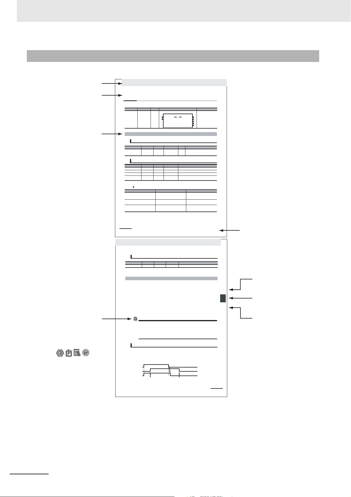
Page Structure
The following page structure is used in this manual.
4
NY-series Motion Control Instructions Reference Manual (W561)

Special Information
Special information in this manual is classified as follows:
Precautions for Safe Use
Precautions on what to do and what not to do to ensure safe usage of the product.
Precautions for Correct Use
Precautions on what to do and what not to do to ensure proper operation and performance.
Additional Information
Additional information to read as required.
This information is provided to increase understanding or make operation easier.
Version Information
Information on differences in specifications and functionality for Controller with different unit versions
and for different versions of the Sysmac Studio are given.
Manual Structure
Note References are provided to more detailed or related information.
NY-series Motion Control Instructions Reference Manual (W561)
5

Manual Structure
6
NY-series Motion Control Instructions Reference Manual (W561)

1
2
3
4
5
A
I
1
2
3
4
5
A
I
Introduction to Motion Control Instructions
Variables and Instructions
Axis Command Instructions
Axes Group Instructions
Common Command Instructions
Appendices
Index
Sections in this Manual
Sections in this Manual
NY-series Motion Control Instructions Reference Manual (W561)
7

Sections in this Manual
8
NY-series Motion Control Instructions Reference Manual (W561)

CONTENTS
CONTENTS
Introduction............................................................................................................... 1
Relevant Manuals...................................................................................................... 2
Manual Structure ...................................................................................................... 3
Sections in this Manual............................................................................................ 7
Terms and Conditions Agreement ........................................................................ 15
Safety Precautions ................................................................................................. 17
Precautions for Safe Use ....................................................................................... 18
Precautions for Correct Use .................................................................................. 19
Regulations and Standards ................................................................................... 20
Versions................................................................................................................... 21
Related Manuals ..................................................................................................... 23
Revision History ..................................................................................................... 26
Section 1 Introduction to Motion Control Instructions
1-1 Motion Control Instructions.................................................................................................... 1-2
Function Blocks for PLCopen® Motion Control . . . . . . . . . . . . . . . . . . . . . . . . . . . . . . . . . . . . . . . . . . . . .1-2
Overview of Motion Control Instructions . . . . . . . . . . . . . . . . . . . . . . . . . . . . . . . . . . . . . . . . . . . . . . . . . . .1-3
Precautions for Master and Auxiliary Axes in Synchronized Control . . . . . . . . . . . . . . . . . . . . . . . . . . . . .1-6
1-2 Basic Information on Motion Control Instructions ............................................................... 1-8
Motion Control Instruction Names . . . . . . . . . . . . . . . . . . . . . . . . . . . . . . . . . . . . . . . . . . . . . . . . . . . . . . .1-8
Languages for Motion Control Instructions . . . . . . . . . . . . . . . . . . . . . . . . . . . . . . . . . . . . . . . . . . . . . . . . .1-8
Motion Control Instruction Locations . . . . . . . . . . . . . . . . . . . . . . . . . . . . . . . . . . . . . . . . . . . . . . . . . . . . .1-9
Multi-execution of Motion Control Instructions . . . . . . . . . . . . . . . . . . . . . . . . . . . . . . . . . . . . . . . . . . . . .1-17
Online Editing of Motion Control Instructions . . . . . . . . . . . . . . . . . . . . . . . . . . . . . . . . . . . . . . . . . . . . . .1-18
Changes in the Operating Mode of the NY-series Controller . . . . . . . . . . . . . . . . . . . . . . . . . . . . . . . . . .1-18
Section 2 Variables and Instructions
2-1 Variables................................................................................................................................... 2-2
MC Common Variables . . . . . . . . . . . . . . . . . . . . . . . . . . . . . . . . . . . . . . . . . . . . . . . . . . . . . . . . . . . . . . .2-3
Axis Variables . . . . . . . . . . . . . . . . . . . . . . . . . . . . . . . . . . . . . . . . . . . . . . . . . . . . . . . . . . . . . . . . . . . . . . .2-4
Axes Group Variables . . . . . . . . . . . . . . . . . . . . . . . . . . . . . . . . . . . . . . . . . . . . . . . . . . . . . . . . . . . . . . . .2-9
Input Variables for Motion Control Instructions . . . . . . . . . . . . . . . . . . . . . . . . . . . . . . . . . . . . . . . . . . . .2-12
Output Variables for Motion Control Instructions . . . . . . . . . . . . . . . . . . . . . . . . . . . . . . . . . . . . . . . . . . .2-25
In-Out Variables for Motion Control Instructions . . . . . . . . . . . . . . . . . . . . . . . . . . . . . . . . . . . . . . . . . . .2-28
2-2 Instructions ............................................................................................................................ 2-30
Common Commands . . . . . . . . . . . . . . . . . . . . . . . . . . . . . . . . . . . . . . . . . . . . . . . . . . . . . . . . . . . . . . . .2-30
Axis Commands . . . . . . . . . . . . . . . . . . . . . . . . . . . . . . . . . . . . . . . . . . . . . . . . . . . . . . . . . . . . . . . . . . . .2-31
Axes Group Commands . . . . . . . . . . . . . . . . . . . . . . . . . . . . . . . . . . . . . . . . . . . . . . . . . . . . . . . . . . . . . .2-32
2-3 PDO Mapping ......................................................................................................................... 2-34
Required Objects . . . . . . . . . . . . . . . . . . . . . . . . . . . . . . . . . . . . . . . . . . . . . . . . . . . . . . . . . . . . . . . . . . .2-34
Objects Required for Specific Instructions . . . . . . . . . . . . . . . . . . . . . . . . . . . . . . . . . . . . . . . . . . . . . . . . 2-36
NY-series Motion Control Instructions Reference Manual (W561)
9

CONTENTS
Section 3 Axis Command Instructions
MC_Power . . . . . . . . . . . . . . . . . . . . . . . . . . . . . . . . . . . . . . . . . . . . . . . . . . . . . . . . . . . . . . . . . . . . 3-3
Variables . . . . . . . . . . . . . . . . . . . . . . . . . . . . . . . . . . . . . . . . . . . . . . . . . . . . . . . . . . . . . . . . . . . . . . . . . . 3-3
Function . . . . . . . . . . . . . . . . . . . . . . . . . . . . . . . . . . . . . . . . . . . . . . . . . . . . . . . . . . . . . . . . . . . . . . . . . . 3-4
MC_MoveJog . . . . . . . . . . . . . . . . . . . . . . . . . . . . . . . . . . . . . . . . . . . . . . . . . . . . . . . . . . . . . . . . . . 3-8
Variables . . . . . . . . . . . . . . . . . . . . . . . . . . . . . . . . . . . . . . . . . . . . . . . . . . . . . . . . . . . . . . . . . . . . . . . . . . 3-8
Function . . . . . . . . . . . . . . . . . . . . . . . . . . . . . . . . . . . . . . . . . . . . . . . . . . . . . . . . . . . . . . . . . . . . . . . . . . 3-9
MC_Home . . . . . . . . . . . . . . . . . . . . . . . . . . . . . . . . . . . . . . . . . . . . . . . . . . . . . . . . . . . . . . . . . . . . 3-16
Variables . . . . . . . . . . . . . . . . . . . . . . . . . . . . . . . . . . . . . . . . . . . . . . . . . . . . . . . . . . . . . . . . . . . . . . . . . 3-16
Function . . . . . . . . . . . . . . . . . . . . . . . . . . . . . . . . . . . . . . . . . . . . . . . . . . . . . . . . . . . . . . . . . . . . . . . . . 3-17
MC_HomeWithParameter . . . . . . . . . . . . . . . . . . . . . . . . . . . . . . . . . . . . . . . . . . . . . . . . . . . . . . . 3-38
Variables . . . . . . . . . . . . . . . . . . . . . . . . . . . . . . . . . . . . . . . . . . . . . . . . . . . . . . . . . . . . . . . . . . . . . . . . . 3-38
Function . . . . . . . . . . . . . . . . . . . . . . . . . . . . . . . . . . . . . . . . . . . . . . . . . . . . . . . . . . . . . . . . . . . . . . . . . 3-41
MC_Move . . . . . . . . . . . . . . . . . . . . . . . . . . . . . . . . . . . . . . . . . . . . . . . . . . . . . . . . . . . . . . . . . . . . 3-44
Variables . . . . . . . . . . . . . . . . . . . . . . . . . . . . . . . . . . . . . . . . . . . . . . . . . . . . . . . . . . . . . . . . . . . . . . . . . 3-44
Function . . . . . . . . . . . . . . . . . . . . . . . . . . . . . . . . . . . . . . . . . . . . . . . . . . . . . . . . . . . . . . . . . . . . . . . . . 3-46
MC_MoveAbsolute . . . . . . . . . . . . . . . . . . . . . . . . . . . . . . . . . . . . . . . . . . . . . . . . . . . . . . . . . . . . . 3-49
Variables . . . . . . . . . . . . . . . . . . . . . . . . . . . . . . . . . . . . . . . . . . . . . . . . . . . . . . . . . . . . . . . . . . . . . . . . . 3-49
Function . . . . . . . . . . . . . . . . . . . . . . . . . . . . . . . . . . . . . . . . . . . . . . . . . . . . . . . . . . . . . . . . . . . . . . . . . 3-51
Sample Programming 1 . . . . . . . . . . . . . . . . . . . . . . . . . . . . . . . . . . . . . . . . . . . . . . . . . . . . . . . . . . . . . . 3-59
Sample Programming 2 . . . . . . . . . . . . . . . . . . . . . . . . . . . . . . . . . . . . . . . . . . . . . . . . . . . . . . . . . . . . . . 3-67
MC_MoveRelative . . . . . . . . . . . . . . . . . . . . . . . . . . . . . . . . . . . . . . . . . . . . . . . . . . . . . . . . . . . . . 3-76
Variables . . . . . . . . . . . . . . . . . . . . . . . . . . . . . . . . . . . . . . . . . . . . . . . . . . . . . . . . . . . . . . . . . . . . . . . . . 3-76
Function . . . . . . . . . . . . . . . . . . . . . . . . . . . . . . . . . . . . . . . . . . . . . . . . . . . . . . . . . . . . . . . . . . . . . . . . . 3-78
MC_MoveVelocity . . . . . . . . . . . . . . . . . . . . . . . . . . . . . . . . . . . . . . . . . . . . . . . . . . . . . . . . . . . . . 3-83
Variables . . . . . . . . . . . . . . . . . . . . . . . . . . . . . . . . . . . . . . . . . . . . . . . . . . . . . . . . . . . . . . . . . . . . . . . . . 3-83
Function . . . . . . . . . . . . . . . . . . . . . . . . . . . . . . . . . . . . . . . . . . . . . . . . . . . . . . . . . . . . . . . . . . . . . . . . . 3-85
Sample Programming . . . . . . . . . . . . . . . . . . . . . . . . . . . . . . . . . . . . . . . . . . . . . . . . . . . . . . . . . . . . . . . 3-90
MC_MoveZeroPosition . . . . . . . . . . . . . . . . . . . . . . . . . . . . . . . . . . . . . . . . . . . . . . . . . . . . . . . . . 3-98
Variables . . . . . . . . . . . . . . . . . . . . . . . . . . . . . . . . . . . . . . . . . . . . . . . . . . . . . . . . . . . . . . . . . . . . . . . . . 3-98
Function . . . . . . . . . . . . . . . . . . . . . . . . . . . . . . . . . . . . . . . . . . . . . . . . . . . . . . . . . . . . . . . . . . . . . . . . 3-100
MC_MoveFeed . . . . . . . . . . . . . . . . . . . . . . . . . . . . . . . . . . . . . . . . . . . . . . . . . . . . . . . . . . . . . . . 3-105
Variables . . . . . . . . . . . . . . . . . . . . . . . . . . . . . . . . . . . . . . . . . . . . . . . . . . . . . . . . . . . . . . . . . . . . . . . . 3-106
Function . . . . . . . . . . . . . . . . . . . . . . . . . . . . . . . . . . . . . . . . . . . . . . . . . . . . . . . . . . . . . . . . . . . . . . . . 3-109
Sample Programming . . . . . . . . . . . . . . . . . . . . . . . . . . . . . . . . . . . . . . . . . . . . . . . . . . . . . . . . . . . . . . 3-122
MC_Stop . . . . . . . . . . . . . . . . . . . . . . . . . . . . . . . . . . . . . . . . . . . . . . . . . . . . . . . . . . . . . . . . . . . . 3-133
Variables . . . . . . . . . . . . . . . . . . . . . . . . . . . . . . . . . . . . . . . . . . . . . . . . . . . . . . . . . . . . . . . . . . . . . . . . 3-133
Function . . . . . . . . . . . . . . . . . . . . . . . . . . . . . . . . . . . . . . . . . . . . . . . . . . . . . . . . . . . . . . . . . . . . . . . . 3-134
MC_ImmediateStop . . . . . . . . . . . . . . . . . . . . . . . . . . . . . . . . . . . . . . . . . . . . . . . . . . . . . . . . . . . 3-142
Variables . . . . . . . . . . . . . . . . . . . . . . . . . . . . . . . . . . . . . . . . . . . . . . . . . . . . . . . . . . . . . . . . . . . . . . . . 3-142
Function . . . . . . . . . . . . . . . . . . . . . . . . . . . . . . . . . . . . . . . . . . . . . . . . . . . . . . . . . . . . . . . . . . . . . . . . 3-143
MC_SetPosition . . . . . . . . . . . . . . . . . . . . . . . . . . . . . . . . . . . . . . . . . . . . . . . . . . . . . . . . . . . . . . 3-147
Variables . . . . . . . . . . . . . . . . . . . . . . . . . . . . . . . . . . . . . . . . . . . . . . . . . . . . . . . . . . . . . . . . . . . . . . . . 3-147
Function . . . . . . . . . . . . . . . . . . . . . . . . . . . . . . . . . . . . . . . . . . . . . . . . . . . . . . . . . . . . . . . . . . . . . . . . 3-148
MC_SetOverride . . . . . . . . . . . . . . . . . . . . . . . . . . . . . . . . . . . . . . . . . . . . . . . . . . . . . . . . . . . . . . 3-153
Variables . . . . . . . . . . . . . . . . . . . . . . . . . . . . . . . . . . . . . . . . . . . . . . . . . . . . . . . . . . . . . . . . . . . . . . . . 3-153
Function . . . . . . . . . . . . . . . . . . . . . . . . . . . . . . . . . . . . . . . . . . . . . . . . . . . . . . . . . . . . . . . . . . . . . . . . 3-154
MC_ResetFollowingError . . . . . . . . . . . . . . . . . . . . . . . . . . . . . . . . . . . . . . . . . . . . . . . . . . . . . . 3-158
Variables . . . . . . . . . . . . . . . . . . . . . . . . . . . . . . . . . . . . . . . . . . . . . . . . . . . . . . . . . . . . . . . . . . . . . . . . 3-158
Function . . . . . . . . . . . . . . . . . . . . . . . . . . . . . . . . . . . . . . . . . . . . . . . . . . . . . . . . . . . . . . . . . . . . . . . . 3-159
MC_CamIn . . . . . . . . . . . . . . . . . . . . . . . . . . . . . . . . . . . . . . . . . . . . . . . . . . . . . . . . . . . . . . . . . . 3-165
Variables . . . . . . . . . . . . . . . . . . . . . . . . . . . . . . . . . . . . . . . . . . . . . . . . . . . . . . . . . . . . . . . . . . . . . . . . 3-165
Function . . . . . . . . . . . . . . . . . . . . . . . . . . . . . . . . . . . . . . . . . . . . . . . . . . . . . . . . . . . . . . . . . . . . . . . . 3-169
Sample Programming 1 . . . . . . . . . . . . . . . . . . . . . . . . . . . . . . . . . . . . . . . . . . . . . . . . . . . . . . . . . . . . . 3-192
Sample Programming 2 . . . . . . . . . . . . . . . . . . . . . . . . . . . . . . . . . . . . . . . . . . . . . . . . . . . . . . . . . . . . . 3-203
MC_CamOut . . . . . . . . . . . . . . . . . . . . . . . . . . . . . . . . . . . . . . . . . . . . . . . . . . . . . . . . . . . . . . . . . 3-219
Variables . . . . . . . . . . . . . . . . . . . . . . . . . . . . . . . . . . . . . . . . . . . . . . . . . . . . . . . . . . . . . . . . . . . . . . . . 3-219
Function . . . . . . . . . . . . . . . . . . . . . . . . . . . . . . . . . . . . . . . . . . . . . . . . . . . . . . . . . . . . . . . . . . . . . . . . 3-220
MC_GearIn . . . . . . . . . . . . . . . . . . . . . . . . . . . . . . . . . . . . . . . . . . . . . . . . . . . . . . . . . . . . . . . . . . 3-224
Variables . . . . . . . . . . . . . . . . . . . . . . . . . . . . . . . . . . . . . . . . . . . . . . . . . . . . . . . . . . . . . . . . . . . . . . . . 3-224
Function . . . . . . . . . . . . . . . . . . . . . . . . . . . . . . . . . . . . . . . . . . . . . . . . . . . . . . . . . . . . . . . . . . . . . . . . 3-226
Sample Programming . . . . . . . . . . . . . . . . . . . . . . . . . . . . . . . . . . . . . . . . . . . . . . . . . . . . . . . . . . . . . . 3-233
10
NY-series Motion Control Instructions Reference Manual (W561)

CONTENTS
MC_GearInPos . . . . . . . . . . . . . . . . . . . . . . . . . . . . . . . . . . . . . . . . . . . . . . . . . . . . . . . . . . . . . . 3-243
Variables . . . . . . . . . . . . . . . . . . . . . . . . . . . . . . . . . . . . . . . . . . . . . . . . . . . . . . . . . . . . . . . . . . . . . . . .3-243
Function . . . . . . . . . . . . . . . . . . . . . . . . . . . . . . . . . . . . . . . . . . . . . . . . . . . . . . . . . . . . . . . . . . . . . . . . .3-246
Sample Programming . . . . . . . . . . . . . . . . . . . . . . . . . . . . . . . . . . . . . . . . . . . . . . . . . . . . . . . . . . . . . . .3-254
MC_GearOut . . . . . . . . . . . . . . . . . . . . . . . . . . . . . . . . . . . . . . . . . . . . . . . . . . . . . . . . . . . . . . . . 3-264
Variables . . . . . . . . . . . . . . . . . . . . . . . . . . . . . . . . . . . . . . . . . . . . . . . . . . . . . . . . . . . . . . . . . . . . . . . .3-264
Function . . . . . . . . . . . . . . . . . . . . . . . . . . . . . . . . . . . . . . . . . . . . . . . . . . . . . . . . . . . . . . . . . . . . . . . . .3-266
MC_MoveLink . . . . . . . . . . . . . . . . . . . . . . . . . . . . . . . . . . . . . . . . . . . . . . . . . . . . . . . . . . . . . . . 3-269
Variables . . . . . . . . . . . . . . . . . . . . . . . . . . . . . . . . . . . . . . . . . . . . . . . . . . . . . . . . . . . . . . . . . . . . . . . .3-269
Function . . . . . . . . . . . . . . . . . . . . . . . . . . . . . . . . . . . . . . . . . . . . . . . . . . . . . . . . . . . . . . . . . . . . . . . . .3-272
Sample Programming . . . . . . . . . . . . . . . . . . . . . . . . . . . . . . . . . . . . . . . . . . . . . . . . . . . . . . . . . . . . . . .3-282
MC_CombineAxes . . . . . . . . . . . . . . . . . . . . . . . . . . . . . . . . . . . . . . . . . . . . . . . . . . . . . . . . . . . 3-292
Variables . . . . . . . . . . . . . . . . . . . . . . . . . . . . . . . . . . . . . . . . . . . . . . . . . . . . . . . . . . . . . . . . . . . . . . . .3-292
Function . . . . . . . . . . . . . . . . . . . . . . . . . . . . . . . . . . . . . . . . . . . . . . . . . . . . . . . . . . . . . . . . . . . . . . . . .3-295
MC_Phasing . . . . . . . . . . . . . . . . . . . . . . . . . . . . . . . . . . . . . . . . . . . . . . . . . . . . . . . . . . . . . . . . 3-304
Variables . . . . . . . . . . . . . . . . . . . . . . . . . . . . . . . . . . . . . . . . . . . . . . . . . . . . . . . . . . . . . . . . . . . . . . . .3-304
Function . . . . . . . . . . . . . . . . . . . . . . . . . . . . . . . . . . . . . . . . . . . . . . . . . . . . . . . . . . . . . . . . . . . . . . . . .3-306
MC_TorqueControl . . . . . . . . . . . . . . . . . . . . . . . . . . . . . . . . . . . . . . . . . . . . . . . . . . . . . . . . . . . 3-312
Variables . . . . . . . . . . . . . . . . . . . . . . . . . . . . . . . . . . . . . . . . . . . . . . . . . . . . . . . . . . . . . . . . . . . . . . . .3-312
Function . . . . . . . . . . . . . . . . . . . . . . . . . . . . . . . . . . . . . . . . . . . . . . . . . . . . . . . . . . . . . . . . . . . . . . . . .3-314
MC_SetTorqueLimit . . . . . . . . . . . . . . . . . . . . . . . . . . . . . . . . . . . . . . . . . . . . . . . . . . . . . . . . . . 3-323
Variables . . . . . . . . . . . . . . . . . . . . . . . . . . . . . . . . . . . . . . . . . . . . . . . . . . . . . . . . . . . . . . . . . . . . . . . .3-323
Function . . . . . . . . . . . . . . . . . . . . . . . . . . . . . . . . . . . . . . . . . . . . . . . . . . . . . . . . . . . . . . . . . . . . . . . . .3-324
MC_ZoneSwitch . . . . . . . . . . . . . . . . . . . . . . . . . . . . . . . . . . . . . . . . . . . . . . . . . . . . . . . . . . . . . 3-330
Variables . . . . . . . . . . . . . . . . . . . . . . . . . . . . . . . . . . . . . . . . . . . . . . . . . . . . . . . . . . . . . . . . . . . . . . . .3-330
Function . . . . . . . . . . . . . . . . . . . . . . . . . . . . . . . . . . . . . . . . . . . . . . . . . . . . . . . . . . . . . . . . . . . . . . . . .3-332
MC_TouchProbe . . . . . . . . . . . . . . . . . . . . . . . . . . . . . . . . . . . . . . . . . . . . . . . . . . . . . . . . . . . . . 3-336
Variables . . . . . . . . . . . . . . . . . . . . . . . . . . . . . . . . . . . . . . . . . . . . . . . . . . . . . . . . . . . . . . . . . . . . . . . .3-336
Function . . . . . . . . . . . . . . . . . . . . . . . . . . . . . . . . . . . . . . . . . . . . . . . . . . . . . . . . . . . . . . . . . . . . . . . . .3-339
Sample Programming . . . . . . . . . . . . . . . . . . . . . . . . . . . . . . . . . . . . . . . . . . . . . . . . . . . . . . . . . . . . . . .3-351
MC_AbortTrigger . . . . . . . . . . . . . . . . . . . . . . . . . . . . . . . . . . . . . . . . . . . . . . . . . . . . . . . . . . . . 3-358
Variables . . . . . . . . . . . . . . . . . . . . . . . . . . . . . . . . . . . . . . . . . . . . . . . . . . . . . . . . . . . . . . . . . . . . . . . .3-358
Function . . . . . . . . . . . . . . . . . . . . . . . . . . . . . . . . . . . . . . . . . . . . . . . . . . . . . . . . . . . . . . . . . . . . . . . . .3-360
MC_AxesObserve . . . . . . . . . . . . . . . . . . . . . . . . . . . . . . . . . . . . . . . . . . . . . . . . . . . . . . . . . . . . 3-363
Variables . . . . . . . . . . . . . . . . . . . . . . . . . . . . . . . . . . . . . . . . . . . . . . . . . . . . . . . . . . . . . . . . . . . . . . . .3-363
Function . . . . . . . . . . . . . . . . . . . . . . . . . . . . . . . . . . . . . . . . . . . . . . . . . . . . . . . . . . . . . . . . . . . . . . . . .3-365
MC_SyncMoveVelocity . . . . . . . . . . . . . . . . . . . . . . . . . . . . . . . . . . . . . . . . . . . . . . . . . . . . . . . . 3-369
Variables . . . . . . . . . . . . . . . . . . . . . . . . . . . . . . . . . . . . . . . . . . . . . . . . . . . . . . . . . . . . . . . . . . . . . . . .3-369
Function . . . . . . . . . . . . . . . . . . . . . . . . . . . . . . . . . . . . . . . . . . . . . . . . . . . . . . . . . . . . . . . . . . . . . . . . .3-371
MC_SyncMoveAbsolute . . . . . . . . . . . . . . . . . . . . . . . . . . . . . . . . . . . . . . . . . . . . . . . . . . . . . . . 3-379
Variables . . . . . . . . . . . . . . . . . . . . . . . . . . . . . . . . . . . . . . . . . . . . . . . . . . . . . . . . . . . . . . . . . . . . . . . .3-379
Function . . . . . . . . . . . . . . . . . . . . . . . . . . . . . . . . . . . . . . . . . . . . . . . . . . . . . . . . . . . . . . . . . . . . . . . . .3-381
MC_Reset . . . . . . . . . . . . . . . . . . . . . . . . . . . . . . . . . . . . . . . . . . . . . . . . . . . . . . . . . . . . . . . . . . 3-386
Variables . . . . . . . . . . . . . . . . . . . . . . . . . . . . . . . . . . . . . . . . . . . . . . . . . . . . . . . . . . . . . . . . . . . . . . . .3-386
Function . . . . . . . . . . . . . . . . . . . . . . . . . . . . . . . . . . . . . . . . . . . . . . . . . . . . . . . . . . . . . . . . . . . . . . . . .3-387
MC_ChangeAxisUse . . . . . . . . . . . . . . . . . . . . . . . . . . . . . . . . . . . . . . . . . . . . . . . . . . . . . . . . . . 3-390
Variables . . . . . . . . . . . . . . . . . . . . . . . . . . . . . . . . . . . . . . . . . . . . . . . . . . . . . . . . . . . . . . . . . . . . . . . .3-390
Function . . . . . . . . . . . . . . . . . . . . . . . . . . . . . . . . . . . . . . . . . . . . . . . . . . . . . . . . . . . . . . . . . . . . . . . . .3-391
MC_DigitalCamSwitch . . . . . . . . . . . . . . . . . . . . . . . . . . . . . . . . . . . . . . . . . . . . . . . . . . . . . . . . 3-394
Variables . . . . . . . . . . . . . . . . . . . . . . . . . . . . . . . . . . . . . . . . . . . . . . . . . . . . . . . . . . . . . . . . . . . . . . . .3-395
Function . . . . . . . . . . . . . . . . . . . . . . . . . . . . . . . . . . . . . . . . . . . . . . . . . . . . . . . . . . . . . . . . . . . . . . . . .3-396
Sample Programming . . . . . . . . . . . . . . . . . . . . . . . . . . . . . . . . . . . . . . . . . . . . . . . . . . . . . . . . . . . . . . .3-406
MC_TimeStampToPos . . . . . . . . . . . . . . . . . . . . . . . . . . . . . . . . . . . . . . . . . . . . . . . . . . . . . . . . 3-413
Variables . . . . . . . . . . . . . . . . . . . . . . . . . . . . . . . . . . . . . . . . . . . . . . . . . . . . . . . . . . . . . . . . . . . . . . . .3-413
Function . . . . . . . . . . . . . . . . . . . . . . . . . . . . . . . . . . . . . . . . . . . . . . . . . . . . . . . . . . . . . . . . . . . . . . . . .3-414
Sample Programming . . . . . . . . . . . . . . . . . . . . . . . . . . . . . . . . . . . . . . . . . . . . . . . . . . . . . . . . . . . . . . .3-417
MC_SyncOffsetPosition . . . . . . . . . . . . . . . . . . . . . . . . . . . . . . . . . . . . . . . . . . . . . . . . . . . . . . . 3-425
Variables . . . . . . . . . . . . . . . . . . . . . . . . . . . . . . . . . . . . . . . . . . . . . . . . . . . . . . . . . . . . . . . . . . . . . . . .3-425
Function . . . . . . . . . . . . . . . . . . . . . . . . . . . . . . . . . . . . . . . . . . . . . . . . . . . . . . . . . . . . . . . . . . . . . . . . .3-427
NY-series Motion Control Instructions Reference Manual (W561)
11

CONTENTS
Section 4 Axes Group Instructions
MC_GroupEnable . . . . . . . . . . . . . . . . . . . . . . . . . . . . . . . . . . . . . . . . . . . . . . . . . . . . . . . . . . . . . . . 4-2
Variables . . . . . . . . . . . . . . . . . . . . . . . . . . . . . . . . . . . . . . . . . . . . . . . . . . . . . . . . . . . . . . . . . . . . . . . . . . 4-2
Function . . . . . . . . . . . . . . . . . . . . . . . . . . . . . . . . . . . . . . . . . . . . . . . . . . . . . . . . . . . . . . . . . . . . . . . . . . 4-3
MC_GroupDisable . . . . . . . . . . . . . . . . . . . . . . . . . . . . . . . . . . . . . . . . . . . . . . . . . . . . . . . . . . . . . . 4-6
Variables . . . . . . . . . . . . . . . . . . . . . . . . . . . . . . . . . . . . . . . . . . . . . . . . . . . . . . . . . . . . . . . . . . . . . . . . . . 4-6
Function . . . . . . . . . . . . . . . . . . . . . . . . . . . . . . . . . . . . . . . . . . . . . . . . . . . . . . . . . . . . . . . . . . . . . . . . . . 4-7
MC_MoveLinear . . . . . . . . . . . . . . . . . . . . . . . . . . . . . . . . . . . . . . . . . . . . . . . . . . . . . . . . . . . . . . . 4-10
Variables . . . . . . . . . . . . . . . . . . . . . . . . . . . . . . . . . . . . . . . . . . . . . . . . . . . . . . . . . . . . . . . . . . . . . . . . . 4-10
Function . . . . . . . . . . . . . . . . . . . . . . . . . . . . . . . . . . . . . . . . . . . . . . . . . . . . . . . . . . . . . . . . . . . . . . . . . 4-12
Sample Programming . . . . . . . . . . . . . . . . . . . . . . . . . . . . . . . . . . . . . . . . . . . . . . . . . . . . . . . . . . . . . . . 4-23
MC_MoveLinearAbsolute . . . . . . . . . . . . . . . . . . . . . . . . . . . . . . . . . . . . . . . . . . . . . . . . . . . . . . . 4-36
Variables . . . . . . . . . . . . . . . . . . . . . . . . . . . . . . . . . . . . . . . . . . . . . . . . . . . . . . . . . . . . . . . . . . . . . . . . . 4-36
Function . . . . . . . . . . . . . . . . . . . . . . . . . . . . . . . . . . . . . . . . . . . . . . . . . . . . . . . . . . . . . . . . . . . . . . . . . 4-38
MC_MoveLinearRelative . . . . . . . . . . . . . . . . . . . . . . . . . . . . . . . . . . . . . . . . . . . . . . . . . . . . . . . . 4-39
Variables . . . . . . . . . . . . . . . . . . . . . . . . . . . . . . . . . . . . . . . . . . . . . . . . . . . . . . . . . . . . . . . . . . . . . . . . . 4-39
Function . . . . . . . . . . . . . . . . . . . . . . . . . . . . . . . . . . . . . . . . . . . . . . . . . . . . . . . . . . . . . . . . . . . . . . . . . 4-41
MC_MoveCircular2D . . . . . . . . . . . . . . . . . . . . . . . . . . . . . . . . . . . . . . . . . . . . . . . . . . . . . . . . . . . 4-42
Variables . . . . . . . . . . . . . . . . . . . . . . . . . . . . . . . . . . . . . . . . . . . . . . . . . . . . . . . . . . . . . . . . . . . . . . . . . 4-42
Function . . . . . . . . . . . . . . . . . . . . . . . . . . . . . . . . . . . . . . . . . . . . . . . . . . . . . . . . . . . . . . . . . . . . . . . . . 4-45
Sample Programming . . . . . . . . . . . . . . . . . . . . . . . . . . . . . . . . . . . . . . . . . . . . . . . . . . . . . . . . . . . . . . . 4-54
MC_GroupStop . . . . . . . . . . . . . . . . . . . . . . . . . . . . . . . . . . . . . . . . . . . . . . . . . . . . . . . . . . . . . . . 4-66
Variables . . . . . . . . . . . . . . . . . . . . . . . . . . . . . . . . . . . . . . . . . . . . . . . . . . . . . . . . . . . . . . . . . . . . . . . . . 4-66
Function . . . . . . . . . . . . . . . . . . . . . . . . . . . . . . . . . . . . . . . . . . . . . . . . . . . . . . . . . . . . . . . . . . . . . . . . . 4-68
MC_GroupImmediateStop . . . . . . . . . . . . . . . . . . . . . . . . . . . . . . . . . . . . . . . . . . . . . . . . . . . . . . . 4-75
Variables . . . . . . . . . . . . . . . . . . . . . . . . . . . . . . . . . . . . . . . . . . . . . . . . . . . . . . . . . . . . . . . . . . . . . . . . . 4-75
Function . . . . . . . . . . . . . . . . . . . . . . . . . . . . . . . . . . . . . . . . . . . . . . . . . . . . . . . . . . . . . . . . . . . . . . . . . 4-76
MC_GroupSetOverride . . . . . . . . . . . . . . . . . . . . . . . . . . . . . . . . . . . . . . . . . . . . . . . . . . . . . . . . . 4-79
Variables . . . . . . . . . . . . . . . . . . . . . . . . . . . . . . . . . . . . . . . . . . . . . . . . . . . . . . . . . . . . . . . . . . . . . . . . . 4-79
Function . . . . . . . . . . . . . . . . . . . . . . . . . . . . . . . . . . . . . . . . . . . . . . . . . . . . . . . . . . . . . . . . . . . . . . . . . 4-80
MC_GroupReadPosition . . . . . . . . . . . . . . . . . . . . . . . . . . . . . . . . . . . . . . . . . . . . . . . . . . . . . . . . 4-83
Variables . . . . . . . . . . . . . . . . . . . . . . . . . . . . . . . . . . . . . . . . . . . . . . . . . . . . . . . . . . . . . . . . . . . . . . . . . 4-83
Function . . . . . . . . . . . . . . . . . . . . . . . . . . . . . . . . . . . . . . . . . . . . . . . . . . . . . . . . . . . . . . . . . . . . . . . . . 4-85
MC_ChangeAxesInGroup . . . . . . . . . . . . . . . . . . . . . . . . . . . . . . . . . . . . . . . . . . . . . . . . . . . . . . . 4-87
Variables . . . . . . . . . . . . . . . . . . . . . . . . . . . . . . . . . . . . . . . . . . . . . . . . . . . . . . . . . . . . . . . . . . . . . . . . . 4-87
Function . . . . . . . . . . . . . . . . . . . . . . . . . . . . . . . . . . . . . . . . . . . . . . . . . . . . . . . . . . . . . . . . . . . . . . . . . 4-89
MC_GroupSyncMoveAbsolute . . . . . . . . . . . . . . . . . . . . . . . . . . . . . . . . . . . . . . . . . . . . . . . . . . . 4-91
Variables . . . . . . . . . . . . . . . . . . . . . . . . . . . . . . . . . . . . . . . . . . . . . . . . . . . . . . . . . . . . . . . . . . . . . . . . . 4-91
Function . . . . . . . . . . . . . . . . . . . . . . . . . . . . . . . . . . . . . . . . . . . . . . . . . . . . . . . . . . . . . . . . . . . . . . . . . 4-93
MC_GroupReset . . . . . . . . . . . . . . . . . . . . . . . . . . . . . . . . . . . . . . . . . . . . . . . . . . . . . . . . . . . . . . . 4-97
Variables . . . . . . . . . . . . . . . . . . . . . . . . . . . . . . . . . . . . . . . . . . . . . . . . . . . . . . . . . . . . . . . . . . . . . . . . . 4-97
Function . . . . . . . . . . . . . . . . . . . . . . . . . . . . . . . . . . . . . . . . . . . . . . . . . . . . . . . . . . . . . . . . . . . . . . . . . 4-98
Section 5 Common Command Instructions
MC_SetCamTableProperty . . . . . . . . . . . . . . . . . . . . . . . . . . . . . . . . . . . . . . . . . . . . . . . . . . . . . . . 5-2
Variables . . . . . . . . . . . . . . . . . . . . . . . . . . . . . . . . . . . . . . . . . . . . . . . . . . . . . . . . . . . . . . . . . . . . . . . . . . 5-2
Function . . . . . . . . . . . . . . . . . . . . . . . . . . . . . . . . . . . . . . . . . . . . . . . . . . . . . . . . . . . . . . . . . . . . . . . . . . 5-3
MC_SaveCamTable . . . . . . . . . . . . . . . . . . . . . . . . . . . . . . . . . . . . . . . . . . . . . . . . . . . . . . . . . . . . . 5-8
Variables . . . . . . . . . . . . . . . . . . . . . . . . . . . . . . . . . . . . . . . . . . . . . . . . . . . . . . . . . . . . . . . . . . . . . . . . . . 5-8
Function . . . . . . . . . . . . . . . . . . . . . . . . . . . . . . . . . . . . . . . . . . . . . . . . . . . . . . . . . . . . . . . . . . . . . . . . . . 5-9
MC_Write . . . . . . . . . . . . . . . . . . . . . . . . . . . . . . . . . . . . . . . . . . . . . . . . . . . . . . . . . . . . . . . . . . . . 5-12
Variables . . . . . . . . . . . . . . . . . . . . . . . . . . . . . . . . . . . . . . . . . . . . . . . . . . . . . . . . . . . . . . . . . . . . . . . . . 5-13
Function . . . . . . . . . . . . . . . . . . . . . . . . . . . . . . . . . . . . . . . . . . . . . . . . . . . . . . . . . . . . . . . . . . . . . . . . . 5-15
MC_GenerateCamTable . . . . . . . . . . . . . . . . . . . . . . . . . . . . . . . . . . . . . . . . . . . . . . . . . . . . . . . . 5-18
Variables . . . . . . . . . . . . . . . . . . . . . . . . . . . . . . . . . . . . . . . . . . . . . . . . . . . . . . . . . . . . . . . . . . . . . . . . . 5-18
Function . . . . . . . . . . . . . . . . . . . . . . . . . . . . . . . . . . . . . . . . . . . . . . . . . . . . . . . . . . . . . . . . . . . . . . . . . 5-21
Sample Programming . . . . . . . . . . . . . . . . . . . . . . . . . . . . . . . . . . . . . . . . . . . . . . . . . . . . . . . . . . . . . . . 5-35
MC_WriteAxisParameter . . . . . . . . . . . . . . . . . . . . . . . . . . . . . . . . . . . . . . . . . . . . . . . . . . . . . . . . 5-47
Variables . . . . . . . . . . . . . . . . . . . . . . . . . . . . . . . . . . . . . . . . . . . . . . . . . . . . . . . . . . . . . . . . . . . . . . . . . 5-47
Function . . . . . . . . . . . . . . . . . . . . . . . . . . . . . . . . . . . . . . . . . . . . . . . . . . . . . . . . . . . . . . . . . . . . . . . . . 5-49
12
NY-series Motion Control Instructions Reference Manual (W561)

CONTENTS
MC_ReadAxisParameter . . . . . . . . . . . . . . . . . . . . . . . . . . . . . . . . . . . . . . . . . . . . . . . . . . . . . . . 5-62
Variables . . . . . . . . . . . . . . . . . . . . . . . . . . . . . . . . . . . . . . . . . . . . . . . . . . . . . . . . . . . . . . . . . . . . . . . . .5-62
Function . . . . . . . . . . . . . . . . . . . . . . . . . . . . . . . . . . . . . . . . . . . . . . . . . . . . . . . . . . . . . . . . . . . . . . . . . .5-64
Appendices
A-1 Instructions for Which Multi-execution Is Supported ..........................................................A-2
A-1-1 Axis and Axes Group Status ....................................................................................................... A-3
A-1-2 State Transitions and Instructions for which Multi-execution Is Supported.................................A-5
A-2 Connecting to NX Units ........................................................................................................A-10
Index
NY-series Motion Control Instructions Reference Manual (W561)
13

14
CONTENTS
NY-series Motion Control Instructions Reference Manual (W561)

Terms and Conditions Agreement
Terms and Conditions Agreement
Warranty, Limitations of Liability
Warranties
z Exclusive Warranty
Omron’s exclusive warranty is that the Products will be free from defects in materials and workmanship for a period of twelve months from the date of sale by Omron (or such other period expressed in
writing by Omron). Omron disclaims all other warranties, express or implied.
z Limitations
OMRON MAKES NO WARRANTY OR REPRESENTATION, EXPRESS OR IMPLIED, ABOUT
NON-INFRINGEMENT, MERCHANTABILITY OR FITNESS FOR A PARTICULAR PURPOSE OF
THE PRODUCTS. BUYER ACKNOWLEDGES THAT IT ALONE HAS DETERMINED THAT THE
PRODUCTS WILL SUITABLY MEET THE REQUIREMENTS OF THEIR INTENDED USE.
Omron further disclaims all warranties and responsibility of any type for claims or expenses based
on infringement by the Products or otherwise of any intellectual property right.
z Buyer Remedy
Omron’s sole obligation hereunder shall be, at Omron’s election, to (i) replace (in the form originally
shipped with Buyer responsible for labor charges for removal or replacement thereof) the non-complying Product, (ii) repair the non-complying Product, or (iii) repay or credit Buyer an amount equal
to the purchase price of the non-complying Product; provided that in no event shall Omron be
responsible for warranty, repair, indemnity or any other claims or expenses regarding the Products
unless Omron’s analysis confirms that the Products were properly handled, stored, installed and
maintained and not subject to contamination, abuse, misuse or inappropriate modification. Return of
any Products by Buyer must be approved in writing by Omron before shipment. Omron Companies
shall not be liable for the suitability or unsuitability or the results from the use of Products in combination with any electrical or electronic components, circuits, system assemblies or any other materials or substances or environments. Any advice, recommendations or information given orally or in
writing, are not to be construed as an amendment or addition to the above warranty.
See http://www.omron.com/global/ or contact your Omron representative for published information.
Limitation on Liability; Etc
OMRON COMPANIES SHALL NOT BE LIABLE FOR SPECIAL, INDIRECT, INCIDENTAL, OR CONSEQUENTIAL DAMAGES, LOSS OF PROFITS OR PRODUCTION OR COMMERCIAL LOSS IN ANY
WAY CONNECTED WITH THE PRODUCTS, WHETHER SUCH CLAIM IS BASED IN CONTRACT,
WARRANTY, NEGLIGENCE OR STRICT LIABILITY.
Further, in no event shall liability of Omron Companies exceed the individual price of the Product on
which liability is asserted.
NY-series Motion Control Instructions Reference Manual (W561)
15

Terms and Conditions Agreement
Application Considerations
Suitability of Use
Omron Companies shall not be responsible for conformity with any standards, codes or regulations
which apply to the combination of the Product in the Buyer’s application or use of the Product. At
Buyer’s request, Omron will provide applicable third party certification documents identifying ratings
and limitations of use which apply to the Product. This information by itself is not sufficient for a complete determination of the suitability of the Product in combination with the end product, machine, system, or other application or use. Buyer shall be solely responsible for determining appropriateness of
the particular Product with respect to Buyer’s application, product or system. Buyer shall take application responsibility in all cases.
NEVER USE THE PRODUCT FOR AN APPLICATION INVOLVING SERIOUS RISK TO LIFE OR
PROPERTY WITHOUT ENSURING THAT THE SYSTEM AS A WHOLE HAS BEEN DESIGNED TO
ADDRESS THE RISKS, AND THAT THE OMRON PRODUCT(S) IS PROPERLY RATED AND
INSTALLED FOR THE INTENDED USE WITHIN THE OVERALL EQUIPMENT OR SYSTEM.
Programmable Products
Omron Companies shall not be responsible for the user’s programming of a programmable Product, or
any consequence thereof.
Disclaimers
Performance Data
Data presented in Omron Company websites, catalogs and other materials is provided as a guide for
the user in determining suitability and does not constitute a warranty. It may represent the result of
Omron’s test conditions, and the user must correlate it to actual application requirements. Actual performance is subject to the Omron’s Warranty and Limitations of Liability.
Change in Specifications
Product specifications and accessories may be changed at any time based on improvements and other
reasons. It is our practice to change part numbers when published ratings or features are changed, or
when significant construction changes are made. However, some specifications of the Product may be
changed without any notice. When in doubt, special part numbers may be assigned to fix or establish
key specifications for your application. Please consult with your Omron’s representative at any time to
confirm actual specifications of purchased Product.
16
Errors and Omissions
Information presented by Omron Companies has been checked and is believed to be accurate; however, no responsibility is assumed for clerical, typographical or proofreading errors or omissions.
NY-series Motion Control Instructions Reference Manual (W561)

Safety Precautions
Refer to the following manuals for safety precautions.
• NY-series Industrial Box PC Hardware User’s Manual (Cat. No. W556)
• NY-series Industrial Panel PC Hardware User’s Manual (Cat. No. W557)
• NY-series Industrial Panel PC / Industrial Box PC Software User’s Manual (Cat. No. W558)
Safety Precautions
NY-series Motion Control Instructions Reference Manual (W561)
17

Precautions for Safe Use
Precautions for Safe Use
Refer to the following manuals for precautions for safe use.
• NY-series Industrial Box PC Hardware User’s Manual (Cat. No. W556)
• NY-series Industrial Panel PC Hardware User’s Manual (Cat. No. W557)
• NY-series Industrial Panel PC / Industrial Box PC Software User’s Manual (Cat. No. W558)
18
NY-series Motion Control Instructions Reference Manual (W561)

Precautions for Correct Use
Refer to the following manuals for precautions for correct use.
• NY-series Industrial Box PC Hardware User’s Manual (Cat. No. W556)
• NY-series Industrial Panel PC Hardware User’s Manual (Cat. No. W557)
• NY-series Industrial Panel PC / Industrial Box PC Software User’s Manual (Cat. No. W558)
Precautions for Correct Use
NY-series Motion Control Instructions Reference Manual (W561)
19

Regulations and Standards
Regulations and Standards
Conformance to EU Directives
Applicable Directives
•EMC Directives
Concepts
z EMC Directive
OMRON devices that comply with EU Directives also conform to the related EMC standards so that
they can be more easily built into other devices or the overall machine. The actual products have
been checked for conformity to EMC standards.
Whether the products conform to the standards in the system used by the customer, however, must
be checked by the customer. EMC-related performance of the OMRON devices that comply with EU
Directives will vary depending on the configuration, wiring, and other conditions of the equipment or
control panel on which the OMRON devices are installed. The customer must, therefore, perform the
final check to confirm that devices and the overall machine conform to EMC standards.
* Applicable EMC (Electromagnetic Compatibility) standards are as follows:
EMS (Electromagnetic Susceptibility): EN 61131-2
EMI (Electromagnetic Interference): EN 61131-2 (Radiated emission: 10-m regulations)
*
z Conformance to EU Directives
The NY-series Controllers comply with EU Directives. To ensure that the machine or device in which
the NY-series Controller is used complies with EU Directives, the Controller must be installed as follows:
• The NY-series Controller must be installed within a control panel.
• You must use the power supply in SELV specifications for the DC power supplies connected to DC
Power Supply Units and I/O Units.
• NY-series Controllers that comply with EU Directives also conform to the Common Emission Standard (EN 61000-6-4). Radiated emission characteristics (10-m regulations) may vary depending
on the configuration of the control panel used, other devices connected to the control panel, wiring, and other conditions.
You must therefore confirm that the overall machine or equipment complies with EU Directives.
Software Licenses and Copyrights
This product incorporates certain third party software. The license and copyright information associated with this software is available at http://www.fa.omron.co.jp/nj_info_e/.
20
NY-series Motion Control Instructions Reference Manual (W561)
Versions
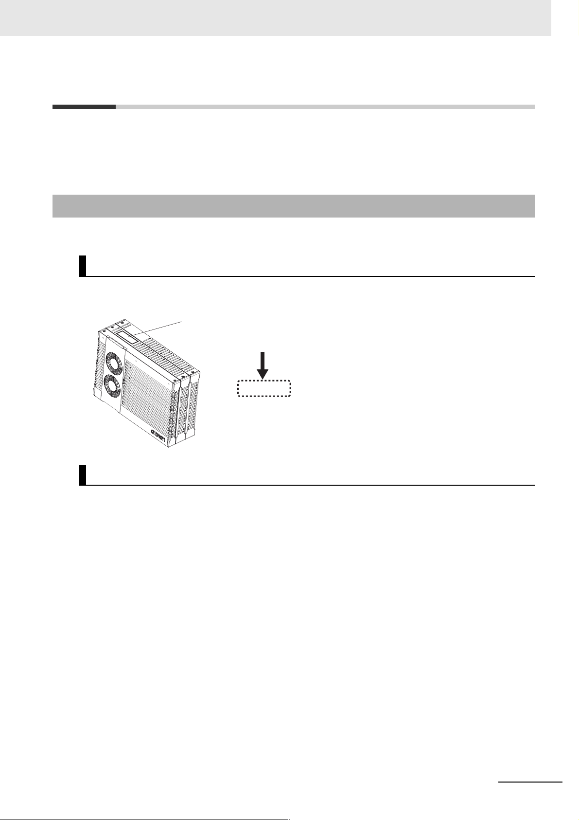
ID information indication
Unit version
Ver.1.
Hardware revisions and unit versions are used to manage the hardware and software in NY-series Controllers and EtherCAT slaves. The hardware revision or unit version is updated each time there is a
change in hardware or software specifications. Even when two Units or EtherCAT slaves have the same
model number, they will have functional or performance differences if they have different hardware revisions or unit versions.
Checking Versions
You can check versions on the ID information indications or with the Sysmac Studio.
Checking Unit Versions on ID Information Indications
The unit version is given on the ID information indication on the back side of the product.
The ID information on an NY-series NY52-1 Controller is shown below.
Versions
Checking Unit Versions with the Sysmac Studio
You can use the Sysmac Studio to check unit versions. The procedure is different for Units and for EtherCAT slaves.
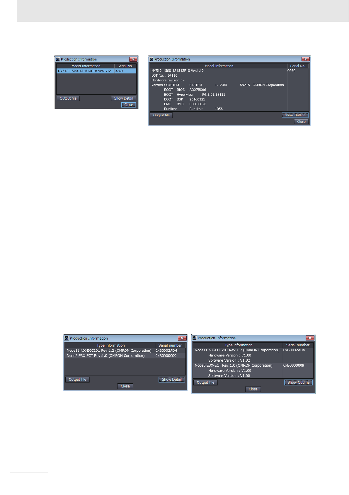
z Checking the Unit Version of an NY-series Controller
You can use the Production Information while the Sysmac Studio is online to check the unit version
of a Unit. You can only do this for the Controller.
• Right-click CPU Rack under Configurations and Setup − CPU/Expansion Racks in the Multiv-
iew Explorer and select Production Information.
The Production Information Dialog Box is displayed.
z Changing Information Displayed in Production Information Dialog Box
Click the Show Detail or Show Outline Button at the lower right of the Production Information Dialog Box.
The view will change between the production information details and outline.
NY-series Motion Control Instructions Reference Manual (W561)
21
Versions
Outline View Detail View
The information that is displayed is different for the Outline View and Detail View. The Detail View
displays the unit version, hardware revision, and other versions. The Outline View displays only the
unit version.
z Checking the Unit Version of an EtherCAT Slave
You can use the Production Information while the Sysmac Studio is online to check the unit version
of an EtherCAT slave. Use the following procedure to check the unit version.
1 Double-click EtherCAT under Configurations and Setup in the Multiview Explorer. Or, right-
click EtherCAT under Configurations and Setup and select Edit from the menu.
The EtherCAT Tab Page is displayed.
2 Right-click the master on the EtherCAT Tab Page and select Display Production Information.
The Production Information Dialog Box is displayed.
The unit version is displayed after “Rev.”
z Changing Information Displayed in Production Information Dialog Box
Click the Show Detail or Show Outline Button at the lower right of the Production Information Dialog Box.
The view will change between the production information details and outline.
22
Outline View Detail View
NY-series Motion Control Instructions Reference Manual (W561)

Related Manuals
The followings are the manuals related to this manual. Use these manuals for reference.
Manual name Cat. No. Model numbers Application Description
NY-series
IPC Machine Controller
Industrial Panel PC
Hardware
User’s Manual
NY-series
IPC Machine Controller
Industrial Box PC
Hardware
User’s Manual
NY-series
IPC Machine Controller
Industrial Panel PC / Industrial Box PC
Setup
User’s Manual
NY-series
IPC Machine Controller
Industrial Panel PC / Industrial Box PC
Software
User’s Manual
NY-series
Instructions
Reference Manual
NY-series
IPC Machine Controller
Industrial Panel PC / Industrial Box PC
Motion Control
User’s Manual
NY-series
Motion Co
Reference Manual
ntro
l Instructions
W557 NY532-1 Learning the basic
specifications of the
NY-series Industrial
Panel PCs, including
introductory information, designing, installation, and
maintenance.
Mainly hardware
information is provided.
W556 NY512-1 Learning the basic
specifications of the
NY-series Industrial
Box PCs, including
introductory information, designing, installation, and
maintenance.
Mainly hardware
information is provided.
W568 NY532-1
NY512-1
W558 NY532-1
NY512-1
W560 NY532-1
NY512-1
W559 NY532-1
NY512-1
W561 NY532-1
NY512-1
Learning about initial
setting of the NYseries Industrial PCs
and how to prepare
the Controller.
Learning how to program and set up the
Controller functions
of an NY-series
Industrial PC.
Learning detailed
specifications on the
basic instructions of
the NY-series Industrial PC.
Learning about
motion control settings and programming concepts of an
NY-series Industrial
PC.
Learning about the
specifications of the
motion control
instructions of an NYseries Industrial PC.
An introduction to the entire NY-series system
is provided along with the following information on the Industrial Panel PC.
• Features and system configuration
• Introduction
• Part names and functions
• General specifications
• Installation and wiring
• Maintenance and inspection
An introduction to the entire NY-series system
is provided along with the following information on the Industrial Box PC.
• Features and system configuration
• Introduction
• Part names and functions
• General specifications
• Installation and wiring
• Maintenance and inspection
The following information is provided on an
introduction to the entire NY-series system.
• Two OS systems
• Initial settings
• Industrial PC Support Utility
• NYCompolet
• Industrial PC API
• Backup and recovery
The following information is provided on the
NY-series Controller functions.
• Controller operation
• Controller features
• Controller settings
• Programming based on IEC 61131-3 language specifications
The instructions in the instruction set (IEC
61131-3 specifications) are described.
The settings and operation of the Controller
and programming concepts for motion control
are described.
The motion control instructions are
described.
Related Manuals
NY-series Motion Control Instructions Reference Manual (W561)
23

Related Manuals
Manual name Cat. No. Model numbers Application Description
NY-series
IPC Machine Controller
Industrial Panel PC / Industrial Box PC
Built-in EtherCAT® Port
User’s Manual
NY-series
IPC Machine Controller
Industrial Panel PC / Industrial Box PC
Built-in EtherNet/IP™ Port
User’s Manual
NY-series
Troubleshooting
Manual
Sysmac Studio Version 1
Operation Manual
NX-series
EtherCAT® Coupler Unit
User’s Manual
NX-series NX Units User’s
Manuals
NX-series Data
Reference Manual
GX-series EtherCAT Slave
Units User’s Manual
W562 NY532-1
NY512-1
W563 NY532-1
NY512-1
W564 NY532-1
NY512-1
W504 SYSMAC
W519 NX-ECC Learning how to use
W521 NX-ID
W522 NX-AD
W523 NX-PD1
W524 NX-EC0
W525 NX- Referring to the list of
W488 GX-ID
-SE2
NX-IA
NX-OC
NX-OD
NX-DA
NX-TS
NX-PF0
NX-PC0
NX-TBX
ECS
NX-
NX-
PG0
GX-OD
GX-OC
GX-MD
GX-AD
GX-DA
GX-EC
XWT-ID
XWT-OD
Using the built-in EtherCAT port in an NYseries Industrial PC.
Using the built-in EtherNet/IP port in an
NY-series Industrial
PC.
Learning about the
errors that may be
detected in an NYseries Industrial PC.
Learning about the
operating procedures and functions
of the Sysmac Studio.
an NX-series EtherCAT Coupler Unit and
EtherCAT Slave Terminals.
Learning how to use
NX Units.
data required for NXseries unit system
configuration.
Learning how to use
the EtherCAT remote
I/O terminals.
Information on the built-in EtherCAT port is
provided.
This manual provides an introduction and
provides information on the configuration,
features, and setup.
Information on the built-in EtherNet/IP port is
provided.
Information is provided on the basic setup,
tag data links, and other features.
Concepts on managing errors that may be
detected in an NY-series Controller and information on individual errors are described.
Describes the operating procedures of the
Sysmac Studio.
The following items are described: the overall
system and configuration methods of an EtherCAT Slave Terminal (which consists of an
NX-series EtherCAT Coupler Unit and NX
Units), and information on hardware, setup,
and functions to set up, control, and monitor
NX Units through EtherCAT.
Describe the hardware, setup methods, and
functions of the NX Units.
Manuals are available for the following Units.
Digital I/O Units, Analog I/O Units, System
Units, and Position Interface Units.
Provides the list of data required for system
configuration including the power consumption and weight of each NX-series Unit.
Describes the hardware, setup methods, and
functions of the EtherCAT remote I/O terminals.
24
NY-series Motion Control Instructions Reference Manual (W561)

Manual name Cat. No. Model numbers Application Description
AC Servomotors/Servo
Drives 1S-series with Built-in
EtherCAT® Communications
User’s Manual
AC Servomotors/Servo
Drives G5-series with Built-in
EtherCAT® Communications
User’s Manual
I586 R88M-1
R88D-1SN-ECT
I573 R88M-K
R88D-KN-ECT-R
I576 R88M-K
R88D-KN-ECT
I577 R88L-EC-
R88D-KN-ECT-L
Learning how to use
the Servomotors/Servo Drives
with built-in EtherCAT Communications.
Learning how to use
the Servomotors/Servo Drives
with built-in EtherCAT Communications.
Describes the hardware, setup methods and
functions of the Servomotors/Servo Drives
with built-in EtherCAT Communications.
Describes the hardware, setup methods and
functions of the Servomotors/Servo Drives
with built-in EtherCAT Communications.
The linear motor type model and the model
dedicated for position controls are available in
G5-series.
Related Manuals
NY-series Motion Control Instructions Reference Manual (W561)
25

Revision History
W561-E1-01
Revision code
Cat. No.
Revision History
A manual revision code appears as a suffix to the catalog number on the front and back covers of the
manual.
Revision code Date Revised content
01 September 2016 Original production
26
NY-series Motion Control Instructions Reference Manual (W561)

Introduction to Motion Control
Instructions
This section gives an introduction to motion control instructions supported by NY-series
Controllers.
1-1 Motion Control Instructions . . . . . . . . . . . . . . . . . . . . . . . . . . . . . . . . . . . . . 1-2
1-2 Basic Information on Motion Control Instructions . . . . . . . . . . . . . . . . . . . 1-8
1
NY-series Motion Control Instructions Reference Manual (W561)
1-1

1 Introduction to Motion Control Instructions
Additional Information
1-1 Motion Control Instructions
Motion control instructions are used in the user program to execute motion controls for an NY-series
Controller. These instructions are defined as function blocks.
The motion control instructions of the MC Function Module are based on the technical specifications of
®
function blocks for PLCopen
There are two types of motion control instructions: PLCopen
are unique to the MC Function Module. This section provides an overview of the PLCopen
control function blocks and motion control instructions.
For details on motion control instructions, refer to the NY-series Industrial Panel PC / Industrial Box PC
Motion Control User’s Manual (Cat. No. W559).
Refer to the NX-series Position Interface Units User’s Manual (Cat. No. W524) for information on using
the NX-series Position Interface Units.
motion control.
®
-defined instructions and instructions that
®
motion
Function Blocks for PLCopen® Motion Control
®
PLCopen
specified in IEC 61131-3 (JIS B 3503). Single-axis positioning, electronic cams, and multi-axes coordinated control are defined along with basic procedures for executing instructions.
By using PLCopen
hardware dependence. Costs for training and support are also reduced.
standardizes motion control function blocks to define a program interface for the languages
®
motion control function blocks, programming can be more easily reused without
PLCopen
PLCopen® is a promotion body for IEC 61131-3 that has its headquarters in Europe and a worldwide membership structure. IEC 61131-3 is an international standard for PLC programming.
PLCopen
that have concerns related to the Japanese market.
• The website of headquarters of PLCopen
®
®
Japan is the promotion committee for the Japanese market and consists of members
®
in Europe is http://www.plcopen.org/.
1-2
NY-series Motion Control Instructions Reference Manual (W561)
 Loading...