

Page 1
Safety Network Controller
NX-series
Safety Control Unit/
Communication Control Unit
User's Manual
NX-SL5£££
NX-SI££££
NX-SO££££
NX-CSG£££
Safety Control Unit
Communication Control Unit
Z395-E1-09
Page 2

NOTE
• All rights reserved. No part of this publication may be reproduced, stored in a retrieval system, or
transmitted, in any form, or by any means, mechanical, electronic, photocopying, recording, or otherwise, without the prior written permission of OMRON.
• No patent liability is assumed with respect to the use of the information contained herein.
Moreover
tion contained in this manual is subject to change without notice.
, because OMRON is constantly striving to improve its high-quality products, the informa-
• Every precaution has been taken in the preparation of this manual. Nevertheless, OMRON as-
sumes no responsibility for errors or omissions.
Neither is any liability assumed for damages resulting from the use of the information contained in
this publication.
Trademarks
• Sysmac and SYSMAC are trademarks or registered trademarks of OMRON Corporation in Japan
and other countries for OMRON factory automation products.
• Microsoft, Windows, Excel, and V
crosoft Corporation in the United States and other countries.
• EtherCAT
GmbH, Germany.
• Safety over EtherCAT
Automation GmbH, Germany.
®
is registered trademark and patented technology, licensed by Beckhoff Automation
®
is a registered trademark and a patented technology licensed by Beckhoff
isual Basic are either registered trademarks or trademarks of Mi-
• ODVA, CIP, CompoNet, DeviceNet, EtherNet/IP, and CIP Safety are trademarks of ODVA.
• The SD and SDHC logos are trademarks of SD-3C, LLC.
Other company names and product names in this document are the trademarks or registered trademarks of their respective companies.
Copyrights
• Microsoft product screen shots reprinted with permission from Microsoft Corporation.
• This product incorporates certain third party software. The license and copyright information associ-
ated with this software is available at
http://www.fa.omron.co.jp/nj_info_e/.
Page 3

Introduction
Thank you for purchasing an NX-series Safety Control Unit / Communication Control Unit.
This manual contains information that is necessary to use the NX-series Safety Control Unit / Communication Control Unit.
Please read this manual and make sure you understand the functionality and performance of the Unit
before you attempt to use it in a control system.
Keep this manual in a safe place where it will be available for reference during operation.
Intended Audience
This manual is intended for the following personnel, who must also have knowledge of electrical systems (an electrical engineer or the equivalent).
• Personnel in charge of introducing FA systems.
• Personnel in charge of designing FA systems.
• Personnel in charge of installing and maintaining FA systems.
• Personnel in charge of managing FA systems and facilities.
• Personnel with the qualifications, authority, and responsibility for providing safety at each phase of
the lifecycle of the machine: design, installation, operation, maintenance, and disposal.
• Personnel with a knowledge of functional safety.
For programming, this manual is intended for personnel who understand the programming language
specifications in international standard IEC 61131-3 or Japanese standard JIS B 3503.
Introduction
Applicable Products
This manual covers the following products.
• NX-series Safety Control Units
NX-SL5£££
NX-SI££££
NX-SO££££
• NX-series Communication Control Unit
NX-CSG£££
Note that this manual provides information for using an NX-series Safety Control Unit described above
together with an NX-series Communication Control Unit. When you use it with an NJ/NX-series CPU
Unit, an EtherCAT Coupler Unit, or an EtherNet/IP Coupler Unit, refer to the NX-series Safety Control
Unit User’s Manual (Cat. No. Z930).
NX-series Safety Control Unit/Communication Control Unit User's Manual (Z395)
1
Page 4

Introduction
2
NX-series Safety Control Unit/Communication Control Unit User's Manual (Z395)
Page 5
Sections in this Manual
1 10
2
Overview
System Configuration and
Configuration Devices
3
Specifications of
Configuration Units
12
4
Designing the Power
Supply System
13
5
Installation and Wiring
14
6
15
Troubleshooting
Communications Load
7
Settings
16
Inspection and
Maintenance
8
Programming
A
Appendices
9
Checking Operation
and Actual Operation
I
Index
11
5
14
6
15
7
16
8 A
9 I
Safety Network
Controller Operation
Calculating Safety
Reaction Times
Safety Unit Restore
Safety Data Logging
Backup Functions of the
Communication Control Unit
1
2
3
4
10
11
12
13
Sections in this Manual
NX-series Safety Control Unit/Communication Control Unit User's Manual (Z395)
3
Page 6

CONTENTS
CONTENTS
Introduction .............................................................................................................. 1
Intended Audience
Applicable Products ......................................................................................................................................... 1
Sections in this Manual ........................................................................................... 3
Relevant Manuals................................................................................................... 13
Manual Structure.................................................................................................... 15
Page Structure...............................................................................................................................................15
Special Information ........................................................................................................................................ 16
Precaution on Terminology ............................................................................................................................16
Terms and Conditions Agreement........................................................................ 17
Warranty, Limitations of Liability ....................................................................................................................17
Application Considerations ............................................................................................................................18
Disclaimers ....................................................................................................................................................18
...........................................................................................................................................1
Safety Precautions................................................................................................. 20
Definition of Precautionary Information..........................................................................................................20
Symbols ......................................................................................................................................................... 20
Warnings........................................................................................................................................................21
Cautions.........................................................................................................................................................27
Precautions for Safe Use ...................................................................................... 28
Precautions for Correct Use ................................................................................. 35
Regulations and Standards .................................................................................. 39
Conformance to EU Directives ......................................................................................................................39
Conformance to EN ISO 13849-1 and IEC/EN 62061...................................................................................41
Conformance to UL and CSA Standards.......................................................................................................41
Conformance to Shipbuilding Standards .......................................................................................................41
Conformance to KC Certification ...................................................................................................................41
Unit Versions.......................................................................................................... 43
Unit Versions..................................................................................................................................................43
Unit Versions of Units and Sysmac Studio Versions......................................................................................45
Related Manuals..................................................................................................... 47
Terminology............................................................................................................ 48
Revision History..................................................................................................... 52
Section 1 Overview
1-1 Overview of the Safety Network Controller ......................................................................... 1-2
1-1-1
1-1-2 Introduction to the System Configurations ..................................................................................1-4
1-2 Procedure ...............................................................................................................................1-7
1-2-1 Overall Procedure .......................................................................................................................1-7
1-2-2 Detailed Procedures....................................................................................................................1-8
4
Features ......................................................................................................................................1-2
NX-series Safety Control Unit/Communication Control Unit User's Manual (Z395)
Page 7

CONTENTS
Section 2 System Configuration and Configuration Devices
2-1 Basic Configuration...............................................................................................................2-2
2-1-1
2-1-2 EtherNet/IP Field Network Configuration ....................................................................................2-3
2-1-3 Configuration Units......................................................................................................................2-3
CPU Rack Configuration .............................................................................................................2-2
2-2 Connecting the Support Software........................................................................................2-5
2-3 Network Configuration between Controllers.......................................................................2-6
Section 3 Specifications of Configuration Units
3-1 Communication Control Unit ................................................................................................ 3-2
3-1-1
3-1-2 Built-in EtherNet/IP Port Specifications.......................................................................................3-7
3-1-3 Part Names and Functions........................................................................................................3-10
3-1-4 Terminal Blocks .........................................................................................................................3-12
3-1-5 Indicators...................................................................................................................................3-14
3-1-6 ID Information Indication ...........................................................................................................3-21
3-2 Safety CPU Unit....................................................................................................................3-22
3-2-1 Models and Specifications ........................................................................................................3-22
3-2-2 Part Names and Functions........................................................................................................3-26
3-2-3 Indicators...................................................................................................................................3-27
3-3 Safety Input Unit ..................................................................................................................3-32
3-3-1 Models and Specifications ........................................................................................................3-32
3-3-2 Part Names and Functions........................................................................................................3-38
3-3-3 Indicators...................................................................................................................................3-40
3-4 Safety Output Unit ...............................................................................................................3-45
3-4-1 Models and Specifications ........................................................................................................3-45
3-4-2 Part Names and Functions........................................................................................................3-52
3-4-3 Indicators...................................................................................................................................3-55
3-5 End Cover ............................................................................................................................. 3-59
3-5-1 Models and Specifications ........................................................................................................3-59
3-6 SD Memory Cards ................................................................................................................ 3-60
3-6-1 Models and Specifications ........................................................................................................3-60
3-6-2 Purpose.....................................................................................................................................3-60
3-7 Support Software ................................................................................................................. 3-61
3-7-1 Product Model ...........................................................................................................................3-61
3-7-2 Connection ................................................................................................................................3-62
3-8 PFH........................................................................................................................................3-63
Models and Specifications ..........................................................................................................3-2
Section 4 Designing the Power Supply System
4-1 Power Supply System ...........................................................................................................4-2
4-1-1 NX Unit Power Supply and I/O Power Supply.............................................................................4-2
4-1-2 NX-series Power Supply-related Units........................................................................................4-3
4-2 Designing the NX Unit Power Supply System.....................................................................4-9
4-2-1 Procedure for Designing the NX Unit Power Supply System......................................................4-9
4-2-2 Calculation Example for the NX Unit Power Supply..................................................................4-10
4-3 Designing the I/O Power Supply System...........................................................................4-12
4-3-1 I/O Power Supply Method .........................................................................................................4-12
4-3-2 Designing the I/O Power Supply from the NX Bus....................................................................4-13
4-3-3 Designing the I/O Power Supply from External Sources...........................................................4-18
4-3-4 Restrictions on Inrush Current for ON/OFF Operation..............................................................4-19
4-4 Selecting External Power Supplies and Protective Devices............................................4-20
NX-series Safety Control Unit/Communication Control Unit User's Manual (Z395)
5
Page 8

CONTENTS
4-4-1 Selecting the Unit Power Supply...............................................................................................4-20
4-4-2
4-4-3 Selecting Protective Devices.....................................................................................................4-23
Selecting the I/O Power Supplies..............................................................................................4-22
Section 5 Installation and Wiring
5-1 Processing at Power ON .......................................................................................................5-2
5-1-1
5-1-2 Operation When Resetting the Controller from the Sysmac Studio ............................................5-2
5-2 Mounting Units.......................................................................................................................5-4
5-2-1 Installation in a Control Panel .....................................................................................................5-5
5-2-2 Preparations for Installation ........................................................................................................5-9
5-2-3 Installing the Communication Control Unit ................................................................................5-11
5-2-4 Installing and Connecting NX Units...........................................................................................5-13
5-2-5 Mounting the End Cover ...........................................................................................................5-17
5-2-6 Mounting the End Plates ...........................................................................................................5-18
5-2-7 Attaching Markers .....................................................................................................................5-20
5-2-8 Installing and Removing the SD Memory Card .........................................................................5-21
5-2-9 Removal of the Communication Control Unit ............................................................................5-26
5-2-10 Removing NX Units...................................................................................................................5-27
5-2-11 Assembled Appearance and Dimensions .................................................................................5-28
5-3 Wiring....................................................................................................................................5-32
5-3-1 Wiring the Power Supply...........................................................................................................5-33
5-3-2 Wiring the Additional NX Unit Power Supply Unit .....................................................................5-34
5-3-3 Wiring the Additional I/O Power Supply Unit.............................................................................5-34
5-3-4 Wiring the Protective Devices ...................................................................................................5-34
5-3-5 Grounding .................................................................................................................................5-35
5-3-6 Connecting the Built-in EtherNet/IP Port...................................................................................5-39
5-3-7 Wiring to the Screwless Clamping Terminal Blocks ..................................................................5-46
5-4 Control Panel Installation....................................................................................................5-60
5-4-1 Temperature ..............................................................................................................................5-60
5-4-2 Humidity ....................................................................................................................................5-62
5-4-3 Vibration and Shock ..................................................................................................................5-62
5-4-4 Atmosphere...............................................................................................................................5-62
5-4-5 Electrical Environment ..............................................................................................................5-63
5-4-6 Grounding .................................................................................................................................5-67
Power ON Operation...................................................................................................................5-2
Section 6 Safety Network Controller Operation
6-1 Overview of the Safety Network Controller Operation ....................................................... 6-2
6-1-1
6-1-2 Introduction to Communications between NX Units....................................................................6-3
6-1-3 Introduction to CIP Safety Communications ...............................................................................6-3
6-1-4 Introduction to Tag Data Links.....................................................................................................6-4
6-1-5 Calculating the Number of Connections......................................................................................6-9
Introduction to FSoE Communications........................................................................................6-2
6-2 I/O System ............................................................................................................................6-13
6-2-1 Relationship between the Types of Signals and the Types of Communications .......................6-13
6-2-2 Safety Data Types and Standard Data Types ...........................................................................6-13
6-2-3 Specifying Safety Data Types and Standard Data Types .........................................................6-14
6-3 Safety I/O Function ..............................................................................................................6-15
6-3-1 Safety Input Function ................................................................................................................6-15
6-3-2 Safety Output Function .............................................................................................................6-37
Section 7 Settings
7-1 Configuration and Setup Procedures ..................................................................................7-2
6
NX-series Safety Control Unit/Communication Control Unit User's Manual (Z395)
Page 9

CONTENTS
7-2 Part Names and Functions of the Sysmac Studio Window ...............................................7-3
7-3
CPU Rack Configuration and Setup.....................................................................................7-5
7-3-1 Procedures for Creating the CPU Rack Configuration................................................................7-5
7-3-2 Setting and Viewing the NX Unit Settings ...................................................................................7-6
7-3-3 Setting Up the FSoE Communications........................................................................................7-7
7-4 EtherNet/IP Network Configuration and Setup ...................................................................7-9
7-4-1 Setting IP Addresses...................................................................................................................7-9
7-4-2 CIP Safety Connection Settings................................................................................................7-17
7-4-3 Setting Tag Data Links ..............................................................................................................7-25
7-5 Setting the Input and Output Functions ............................................................................7-29
7-5-1 Safety I/O Functions..................................................................................................................7-29
7-5-2 Setting the Standard Input and Output Functions .....................................................................7-32
7-6 Assigning Variables to I/O Ports ........................................................................................7-33
7-6-1 Registering Device Variables ....................................................................................................7-33
7-6-2 Settings of Communications between NX Units........................................................................7-38
7-7 Exposing Variables to Standard Controllers.....................................................................7-40
7-7-1 Exposing Global Variables ........................................................................................................7-40
7-7-2 Setting Exposed Variables ........................................................................................................7-41
7-7-3 Safety CPU Unit Status.............................................................................................................7-45
7-7-4 I/O Ports of Safety I/O Units......................................................................................................7-46
7-7-5 I/O Ports for Standard I/O Units ................................................................................................7-46
7-8 Exporting/Importing Settings Data.....................................................................................7-47
7-8-1 Exporting/Importing the All NX Unit Settings.............................................................................7-47
7-8-2 Exporting/Importing Data for Individual Safety CPU Unit..........................................................7-49
7-8-3 Importing the Safety Unit Restore File ......................................................................................7-51
Section 8 Programming
8-1 POUs (Program Organization Units) .................................................................................... 8-3
8-1-1
8-1-2 Overview of the Three Types of POUs........................................................................................8-3
8-1-3 Differences between Programs, Functions, and Function Blocks...............................................8-4
8-1-4 Details on Programs....................................................................................................................8-5
8-1-5 Details on Function Blocks..........................................................................................................8-6
8-1-6 Details on Functions..................................................................................................................8-10
8-1-7 Instructions................................................................................................................................8-11
8-2 Variables ............................................................................................................................... 8-12
8-2-1 Variables....................................................................................................................................8-12
8-2-2 Types of Variables .....................................................................................................................8-12
8-2-3 Type of User-defined Variable ...................................................................................................8-12
8-2-4 Attributes of Variables ...............................................................................................................8-13
8-2-5 Data Type..................................................................................................................................8-14
8-2-6 Variable Attributes Other Than Data Type.................................................................................8-16
8-2-7 Function Block Instances ..........................................................................................................8-17
8-2-8 Restrictions on Variable Names and Other Safety Program-related Names.............................8-17
8-3 Constants (Literals) .............................................................................................................8-20
8-3-1 Constants ..................................................................................................................................8-20
8-3-2 Types of Constants ...................................................................................................................8-20
8-4 Programming Languages....................................................................................................8-22
8-4-1 Programming Languages..........................................................................................................8-22
8-4-2 FBD Language ..........................................................................................................................8-22
8-5 Programming Operations....................................................................................................8-27
8-5-1 Programming Layer on the Sysmac Studio...............................................................................8-27
8-5-2 Registering POUs .....................................................................................................................8-28
8-5-3 Registering Variables ................................................................................................................8-38
8-5-4 FBD Programming ....................................................................................................................8-46
8-5-5 Program Pattern Copy ..............................................................................................................8-67
POU ............................................................................................................................................8-3
NX-series Safety Control Unit/Communication Control Unit User's Manual (Z395)
7
Page 10

CONTENTS
8-6 Automatic Programming ..................................................................................................... 8-84
8-7 Monitoring Memory Usage for Communication Control Unit .......................................... 8-93
8-8 Monitoring Memory Usage for Safety Control Unit ..........................................................8-94
8-9 Offline Debugging................................................................................................................8-96
8-5-6 Function Block Conversion for Programs..................................................................................8-70
8-5-7
8-5-8 Searching and Replacing ..........................................................................................................8-73
8-5-9 Safety Task Settings..................................................................................................................8-76
8-5-10 Variable Comment Switching Function......................................................................................8-78
8-6-1 Generation Algorithms for Automatic Programming..................................................................8-84
8-6-2 Automatic Programming Settings..............................................................................................8-87
8-6-3 Automatic Programming Execution Procedure .........................................................................8-90
8-9-1 Offline Safety Program Debugging............................................................................................8-96
8-9-2 Monitoring .................................................................................................................................8-99
8-9-3 Controlling BOOL Variables, Changing Present Values, and Using Forced Refreshing...........8-99
8-9-4 Cross References .....................................................................................................................8-99
8-9-5 Setting the Initial Values of Variables ........................................................................................8-99
8-9-6 Feedback Settings ..................................................................................................................8-100
8-9-7 Simple Automatic Test.............................................................................................................8-101
Building ....................................................................................................................................8-71
Section 9 Checking Operation and Actual Operation
9-1 Procedures before Operation and Transferring the Required Data..................................9-3
9-1-1
9-1-2 Data That You Must Transfer before Operation and Data Transfer Procedures.........................9-4
9-2 Transferring the Configuration Information ........................................................................ 9-6
9-2-1 Overview .....................................................................................................................................9-6
9-2-2 Transfer Procedure .....................................................................................................................9-6
9-3 Operating Modes of the Safety CPU Unit ............................................................................9-8
9-3-1 Startup Operating Mode and Changing the Operating Mode......................................................9-8
9-3-2 Operation When Changing Operating Mode.............................................................................9-10
9-3-3 Executable Functions in Each Mode of the Safety CPU Unit.................................................... 9-11
9-4 Changing to DEBUG Mode..................................................................................................9-13
9-5 Checking External Device Wiring.......................................................................................9-16
9-5-1 Overview of Functions for Checking Wiring ..............................................................................9-16
9-5-2 Monitoring Safety I/O Units .......................................................................................................9-16
9-5-3 Troubleshooting Safety I/O Terminals .......................................................................................9-19
9-5-4 Clear All Memory Operation for Safety I/O Units ......................................................................9-20
9-6 Functions for Checking Operation.....................................................................................9-22
9-6-1 Overview of Functions for Checking Operation.........................................................................9-22
9-6-2 Starting and Stopping the Safety Programs in DEBUG Mode ..................................................9-22
9-6-3 Monitoring Variables in the FBD Editor .....................................................................................9-23
9-6-4 Monitoring Variables in a Watch Tab Page................................................................................9-24
9-6-5 Controlling BOOL Variables, Changing Present Values, and Using Forced Refreshing...........9-26
9-6-6 Cross References .....................................................................................................................9-34
9-7 Online Functional Test ........................................................................................................9-37
9-7-1 Online Functional Test Settings.................................................................................................9-37
9-7-2 Online Functional Test Execution Procedure ............................................................................9-41
9-8 Node Name ...........................................................................................................................9-47
9-9 Security Settings..................................................................................................................9-48
9-9-1 Setting the Safety Password .....................................................................................................9-48
9-9-2 Data Protection .........................................................................................................................9-49
9-10 Performing Safety Validation and Operation.....................................................................9-53
9-10-1 Performing Safety Validation .....................................................................................................9-53
9-10-2 Changing to RUN Mode ............................................................................................................9-54
9-10-3 Changing to PROGRAM Mode .................................................................................................9-55
Commissioning Procedure ..........................................................................................................9-3
8
NX-series Safety Control Unit/Communication Control Unit User's Manual (Z395)
Page 11

9-11 Starting and Stopping the Safety Application Monitoring ............................................... 9-57
9-1
1-1 Procedure to Start and Stop the Safety Application Monitoring ................................................9-57
9-11-2 Changing the Monitoring Options for the Safety Application.....................................................9-58
9-12 Uploading Configuration Information and Safety Application Data ...............................9-59
9-12-1 Outline.......................................................................................................................................9-59
9-12-2 Upload Procedures ...................................................................................................................9-59
9-13 Transferring Safety Application Data.................................................................................9-61
9-13-1 Outline.......................................................................................................................................9-61
9-13-2 Transfer Procedure ...................................................................................................................9-61
9-14 Monitoring Controller Status ..............................................................................................9-63
9-15 Restarting and Clearing All Memory .................................................................................. 9-65
9-15-1 Restarting..................................................................................................................................9-65
9-15-2 Clear All Memory Operation......................................................................................................9-65
Section 10 Calculating Safety Reaction Times
10-1 Safety Reaction Time...........................................................................................................10-2
10-1-1
10-1-2 Verifying Safety Reaction Times ...............................................................................................10-4
10-2 Safety Task ...........................................................................................................................10-5
10-2-1 Safety Task................................................................................................................................10-5
10-2-2 Operation of Safety Task...........................................................................................................10-5
10-2-3 Minimum Safety Task Period.....................................................................................................10-5
10-2-4 Setting the Safety Task Period ..................................................................................................10-6
10-3 FSoE Watchdog Timer.........................................................................................................10-7
10-3-1 FSoE Watchdog Timers ............................................................................................................10-7
10-3-2 Checking FSoE Watchdog Timers ............................................................................................10-7
10-3-3 Changing FSoE Watchdog Timers ............................................................................................10-7
10-4 EPI (Data Packet Interval)....................................................................................................10-9
10-4-1 Changing the EPI ......................................................................................................................10-9
10-4-2 EPI Restrictions.........................................................................................................................10-9
Calculating the Safety Reaction Time .......................................................................................10-2
CONTENTS
Section 11 Communications Load
11-1 Adjusting the Communications Load ................................................................................ 11-2
1
1-1-1 Checking Bandwidth Usage for Tag Data Links........................................................................ 11-3
11-1-2 Checking the Device Bandwidth Usage of the CIP Safety Routing ..........................................11-4
11-1-3 Relationship between the Number of Packets Used per Second and Packet Intervals............ 11-5
11-1-4 Adjusting the Device Bandwidth Usage ....................................................................................11-5
Section 12 Safety Unit Restore
12-1 Safety Unit Restore..............................................................................................................12-2
12-1-1 Generate Safety Unit Restore File Function .............................................................................12-2
12-1-2 Safety Unit Restore Function ....................................................................................................12-3
12-1-3 Specifications of a Safety Unit Restore File ..............................................................................12-5
Section 13 Backup Functions of the Communication Control Unit
13-1 The Backup Functions ........................................................................................................13-2
13-1-1
13-1-2 Examples of Operating Procedures for the Backup Functions .................................................13-2
13-1-3 Data that Is Backed Up .............................................................................................................13-4
13-1-4 Types of Backup Functions.......................................................................................................13-5
Applications of Backup Functions .............................................................................................13-2
NX-series Safety Control Unit/Communication Control Unit User's Manual (Z395)
9
Page 12

CONTENTS
13-2 SD Memory Card Backups ................................................................................................ 13-10
13-3 Disabling Backups to SD Memory Cards ........................................................................13-15
13-4 Sysmac Studio Controller Backups ................................................................................. 13-16
13-5 Importing and Exporting Sysmac Studio Backup File Data ..........................................13-20
13-6 Backup Functions when NX Units are Connected..........................................................13-21
13-7 Backup-related Files..........................................................................................................13-23
13-8 Compatibility between Backup-related Files...................................................................13-28
13-9 Functions that cannot be Executed during Backup Functions.....................................13-29
13-1-5 Relation between the Different Types of Backup Functions and Data Groups .........................13-7
13-1-6
13-2-1 Backup (Controller to SD Memory Card) ................................................................................13-10
13-2-2 Restore (SD Memory Card to Controller)................................................................................13-12
13-2-3 Verify (between Controller and SD Memory Card)..................................................................13-13
13-4-1 Backup (Controller to Computer) ............................................................................................13-16
13-4-2 Restore (Computer to Controller)............................................................................................13-17
13-4-3 Verify (between Controller and Computer)..............................................................................13-18
13-6-1 Backing Up Data in NX Units on the Communication Control Unit .........................................13-21
13-6-2 Backup Support Depending on the Controller Status .............................................................13-21
13-6-3 Conditions for Restoring NX Unit Data on the Communication Control Unit...........................13-22
13-7-1 Types of Backup-related Files.................................................................................................13-23
13-7-2 Specifications of a Backup File ...............................................................................................13-23
13-7-3 Specifications of a Restore Command File .............................................................................13-24
13-7-4 Specifications of a Controller Verification Results File............................................................13-25
13-7-5 Specifications of an NX Unit Verification Results File .............................................................13-26
13-8-1 Compatibility between Backup Functions ...............................................................................13-28
Applicable Range of the Backup Functions ..............................................................................13-8
Section 14 Safety Data Logging
14-1 Outline of the Safety Data Logging Function....................................................................14-2
14-2
Creating a Safety Data Logging Settings File with the Sysmac Studio..........................14-4
14-3 Safety Data Logging Operation Procedure .......................................................................14-6
14-4 Checking the Logging Status .............................................................................................14-7
14-4-1 Checking the Seven-segment Indicator ....................................................................................14-7
14-4-2 Checking with System-defined Variables ..................................................................................14-7
14-5 Log File Specifications........................................................................................................14-9
Section 15 Troubleshooting
15-1 Operation after an Error ......................................................................................................15-2
15-1-1
15-1-2 Fatal Errors ..............................................................................................................................15-4
15-1-3 Non-fatal Errors in the Communication Control Unit .................................................................15-6
15-1-4 Checking for Non-fatal Errors .................................................................................................15-15
15-1-5 Resetting Non-fatal Errors ......................................................................................................15-17
15-1-6 Errors Related to the EtherNet/IP Function Module................................................................15-19
15-1-7 Errors Related to Safety Control Units ....................................................................................15-20
15-1-8 Errors on CIP Safety Target Devices ......................................................................................15-21
15-2 Error Troubleshooting Methods ....................................................................................... 15-23
15-2-1 Troubleshooting Flowcharts ....................................................................................................15-23
15-2-2 Troubleshooting Fatal Errors ..................................................................................................15-24
15-2-3 Troubleshooting Non-fatal Errors ...........................................................................................15-25
15-2-4 Troubleshooting When You Cannot Go Online from the Sysmac Studio ................................15-31
15-2-5 Troubleshooting Errors in the Safety Control Unit...................................................................15-35
15-2-6 Troubleshooting the CIP Safety Target Device Errors.............................................................15-42
Overview of Communication Control Unit Status ......................................................................15-2
10
NX-series Safety Control Unit/Communication Control Unit User's Manual (Z395)
Page 13

15-3 Error Descriptions and Corrections.................................................................................15-48
15-3-1
15-3-2 Communication Control Unit Error ..........................................................................................15-51
15-3-3 Safety CPU Unit Error ...........................................................................................................15-163
15-3-4 Safety I/O Unit Error..............................................................................................................15-206
15-3-5 Other Troubles and Corrections............................................................................................15-233
Interpreting Tables...................................................................................................................15-48
15-4 Checking Status with the Network Configurator ..........................................................15-234
15-4-1 The Network Configurator's Device Monitor Function...........................................................15-234
15-4-2 Connection Status Codes and Troubleshooting....................................................................15-242
15-4-3 CIP Safety Connection Status Codes and Troubleshooting..................................................15-249
Section 16 Inspection and Maintenance
16-1 Cleaning and Inspection .....................................................................................................16-2
16-1-1
16-1-2 Periodic Inspections ..................................................................................................................16-2
16-2 Maintenance Procedures ....................................................................................................16-5
16-2-1 Replacing the Communication Control Unit and the Safety CPU Unit ......................................16-5
16-2-2 Replacing Safety I/O Units ........................................................................................................16-6
Cleaning ....................................................................................................................................16-2
CONTENTS
Appendices
A-1 General Specifications ......................................................................................................... A-3
A-2
Dimensions............................................................................................................................ A-4
A-2-1 Communication Control Unit ...................................................................................................... A-4
A-2-2 Safety CPU Unit ......................................................................................................................... A-5
A-2-3 Safety I/O Units .......................................................................................................................... A-5
A-2-4 End Cover .................................................................................................................................. A-6
A-2-5 SD Memory Card ....................................................................................................................... A-6
A-3 NX Objects............................................................................................................................. A-7
A-3-1 Format of NX Object Descriptions.............................................................................................. A-7
A-3-2 Safety CPU Unit ......................................................................................................................... A-7
A-3-3 NX-SID800 Safety Input Unit ....................................................................................................A-11
A-3-4 NX-SIH400 Safety Input Unit ................................................................................................... A-16
A-3-5 NX-SOD400 Safety Output Unit............................................................................................... A-21
A-3-6 NX-SOH200 Safety Output Unit............................................................................................... A-25
A-4 Application Examples......................................................................................................... A-30
A-4-1 Emergency Stop Pushbutton Switches .................................................................................... A-30
A-4-2 Safety Doors ............................................................................................................................ A-32
A-4-3 Safety Laser Scanners............................................................................................................. A-36
A-4-4 Safety Door Switches with Magnetic Locks and Key Selector Switches.................................. A-39
A-4-5 Enable Switches....................................................................................................................... A-43
A-4-6 Two-hand Switches.................................................................................................................. A-47
A-4-7 D40A Non-contact Door Switches............................................................................................ A-50
A-4-8 D40Z Non-contact Door Switches............................................................................................ A-53
A-4-9 Safety Mats and Safety Light Curtains..................................................................................... A-56
A-4-10 Safety Edges............................................................................................................................ A-61
A-4-11 Single Beam Safety Sensor ..................................................................................................... A-63
A-5 Change Tracking................................................................................................................. A-67
A-6 Safety CPU Unit Status....................................................................................................... A-69
A-7 I/O Ports of Safety I/O Units ............................................................................................... A-71
A-7-1 NX-SIH400 Safety Input Unit ................................................................................................... A-71
A-7-2 NX-SID800 Safety Input Unit ................................................................................................... A-73
A-7-3 NX-SOH200 Safety Output Unit............................................................................................... A-74
A-7-4 NX-SOD400 Safety Output Unit............................................................................................... A-75
A-8 CIP Response Codes.......................................................................................................... A-78
NX-series Safety Control Unit/Communication Control Unit User's Manual (Z395)
11
Page 14

CONTENTS
A-9 Icon list for Safety Slave Unit Parameters........................................................................ A-83
A-10 Printing ................................................................................................................................ A-90
A-11 List of Screwless Clamping Terminal Block Models ....................................................... A-92
A-12 I/O Refreshing between NX Units ...................................................................................... A-94
A-13 Units That Support Communications between NX Units .............................................. A-102
A-14 Checking the Signature Code on the Seven-segment Indicator .................................. A-103
A-15 Execution Scenarios for the Simple Automatic Test..................................................... A-104
A-16 Differences in Checking Operation between the Simulator and Safety CPU Unit...... A-106
A-17 I/O Data Enable Flag for CIP Safety Connections.......................................................... A-107
A-18 Version Information .......................................................................................................... A-109
A-8-1 General Status Codes.............................................................................................................. A-78
A-8-2
A-9-1 External Device Icons for Input Devices .................................................................................. A-83
A-9-2 Contact Icons for Input Devices ............................................................................................... A-86
A-9-3 External Device Icons for Output Devices................................................................................ A-88
A-9-4 Contact Icons for Output Devices ............................................................................................ A-89
A-10-1 Selecting the Items to Print ...................................................................................................... A-90
A-10-2 Items that are Printed............................................................................................................... A-90
A-11-1 Model Notation ......................................................................................................................... A-92
A-11-2 List of Terminal Block Models................................................................................................... A-92
A-12-1 I/O Refreshing from the Communication Control Unit to NX Units........................................... A-94
A-12-2 Methods of I/O Refreshing between the Communication Control Unit and NX Units .............. A-94
A-12-3 I/O Response Time for Communications between NX Units.................................................. A-100
A-18-1 Relationship between the Unit Versions and Sysmac Studio Versions.................................. A-109
Extended Status Codes ........................................................................................................... A-80
Index
12
NX-series Safety Control Unit/Communication Control Unit User's Manual (Z395)
Page 15

Relevant Manuals
The following table provides the relevant manuals for this product. Read all of the manuals that are
relevant to your system configuration and application before you use the product.
Most operations on this product are performed from the Sysmac Studio Automation Software. For details on the Sysmac Studio, refer to the Sysmac Studio Version 1 Operation Manual (Cat. No. W504).
Purpose of use
NX-series
Safety Control Unit
User's Manual
User's Manual
Relevant Manuals
NX-series
Safety Control Unit /
Communication Control Unit
NX-series
Communication Control Unit
Built-in Function User's Manual
NX-series
Safety Control Unit
Instructions Reference Manual
Building a safety control system integrated with NJ/NX-series CPU Units
Building a standalone safety control system with
EtherNet/IP Coupler Units
Building a safety network control system with Communication Control Units
Introduction to Communication Control Unit
Setting devices and hardware
NX-SL5£££ Safety CPU Unit
NX-SL3£££ Safety CPU Unit
NX-SI££££ and NX-SO££££ Safety I/O Units
NX-CSG£££ Communication Control Unit
Software settings
NX-SL5£££ Safety CPU Unit
NX-SL3£££ Safety CPU Unit
NX-SI££££ and NX-SO££££ Safety I/O Units
NX-CSG£££ Communication Control Unit
Creating safety programs
Testing operation and debugging
Safety programs
Safety process data communications
Safety I/O functions
Tag data links
Built-in functions for Communication Control Unit
Learning about error corrections
NX-SL5£££ Safety CPU Unit
NX-SL3£££ Safety CPU Unit
NX-SI££££ and NX-SO££££ Safety I/O Units
NX-CSG£££ Communication Control Unit
Maintenance
l
l
l
l l
l l
l
l l
l
l l
l
l l
l l
l l l
l l l
l l
l l
l
l l
l l l
l l
l l
l
NX-series Safety Control Unit/Communication Control Unit User's Manual (Z395)
13
Page 16

Relevant Manuals
Purpose of use
NX-series
Safety Control Unit
User's Manual
User's Manual
NX-series
Safety Control Unit /
Communication Control Unit
NX-series
Communication Control Unit
Built-in Function User's Manual
NX-series
Safety Control Unit
Instructions Reference Manual
NX-SL5£££ Safety CPU Unit
NX-SL3£££ Safety CPU Unit
NX-SI££££ and NX-SO££££ Safety I/O Units
NX-CSG£££ Communication Control Unit
l l
l
l l
l
14
NX-series Safety Control Unit/Communication Control Unit User's Manual (Z395)
Page 17
Manual Structure
4-9
4
Installation and Wiring
NJ-series CPU Unit Hardware User’s Manual (W500)
s
t
i
n
U
gnitn
u
oM
3-4
4
s
t
ne
no
p
m
o
C
rel
l
o
r
t
n
oC
g
n
i
tc
e
n
noC
1
-
3-
4
4-3 Mounting Units
The Units that make up an NJ-series Controller can be connected simply by pressing the Units together
and locking the sliders by moving them toward the back of the Units. The End Cover is connected in the
same way to the Unit on the far right side of the Controller.
1 Join the Units so that the conn ectors fit exactly.
2 The yellow sliders at the top and bottom of each Unit lock the Units together. Move the sliders
toward the back of the Units as shown below until they click into place.
Precautions for Correct UsePrecautions for Correct Use
4-3-1 Connecting Controller Components
Connector
Hook
Hook holes
Slider
Lock
Release
Move the sliders toward the back
until they lock into place.
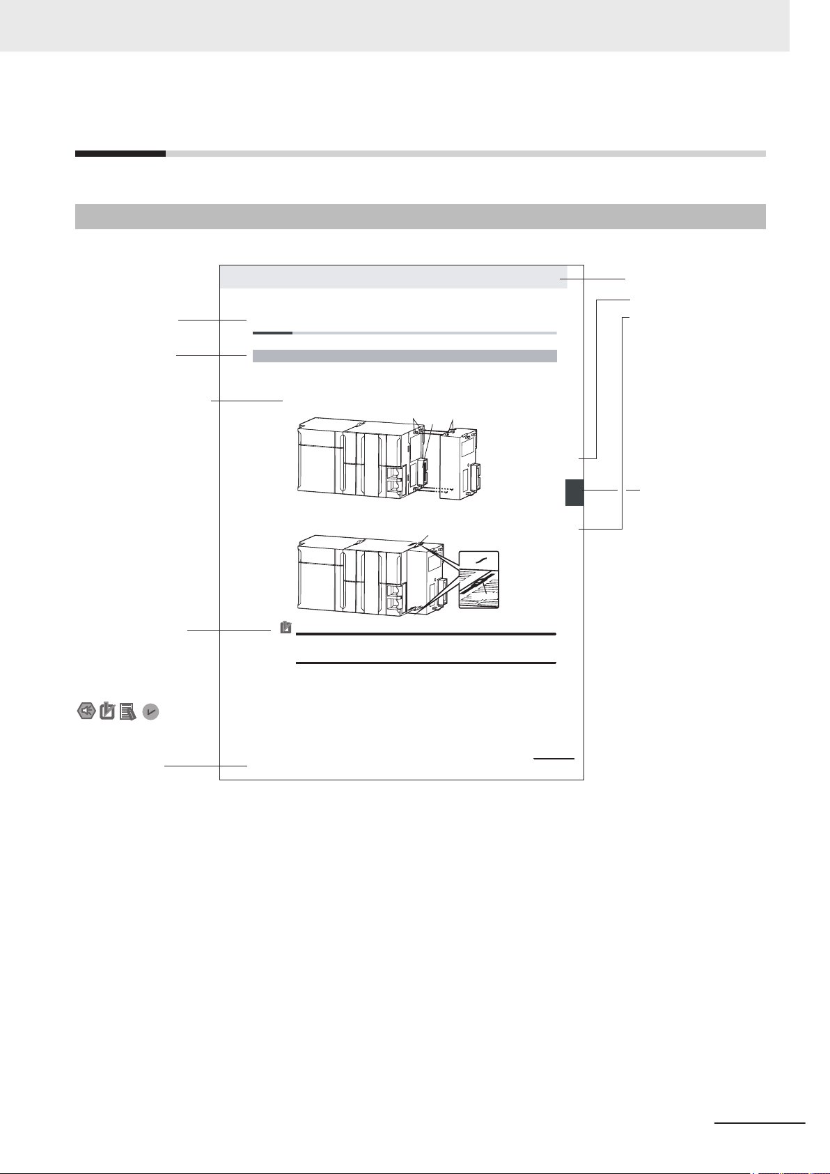
Level 1 heading
Level 2 heading
Level 3 heading
Level 2 heading
A step in a procedure
Manual name
Special information
Level 3 heading
Page tab
Gives the current
headings.
Indicates a procedure.
Icons indicate
precautions, additional
information, or reference
information.
Gives the number
of the main section.
This illustration is provided only as a sample. It may not literally appear in this manual.
Th
e sliders on the tops and bottoms of the Power Supply Unit, CPU Unit, I/O Units, Special I/O
Units, and CPU Bus Units must be completely locked (until they click into place) after connecting
the adjacent Unit connectors.
Page Structure
The following page structure is used in this manual.
Manual Structure
NX-series Safety Control Unit/Communication Control Unit User's Manual (Z395)
15
Page 18
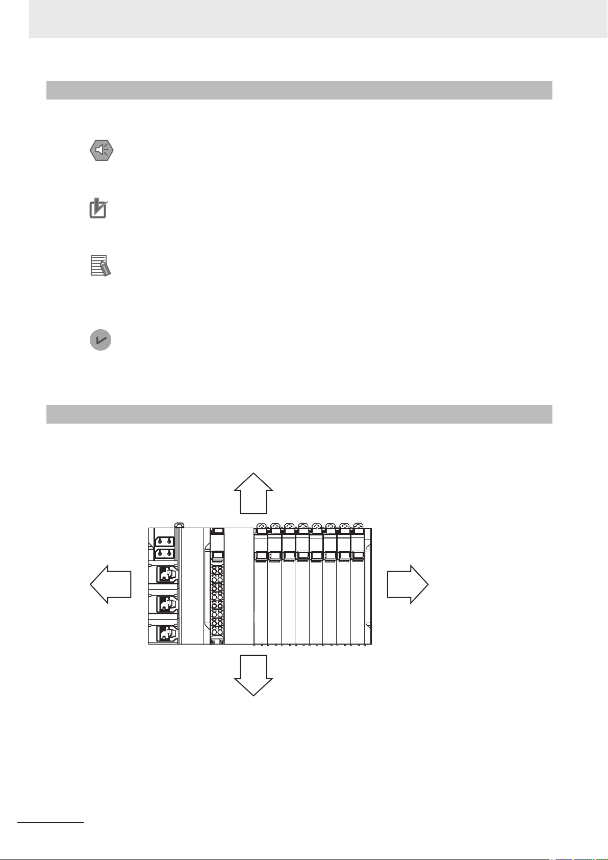
RightLeft
Down
Up
Manual Structure
Special Information
Special information in this manual is classified as follows:
Precautions for Safe Use
Precautions on what to do and what not to do to ensure safe usage of the product.
Precautions for Correct Use
Precautions on what to do and what not to do to ensure proper operation and performance.
Additional Information
Additional information to read as required.
This information is provided to increase understanding or make operation easier
.
Version Information
Information on dif
and for different versions of the Sysmac Studio is given.
ferences in specifications and functionality for Controller with different unit versions
Precaution on Terminology
In this manual, the directions in relation to the Units are given in the following figure, which shows upright installation.
16
NX-series Safety Control Unit/Communication Control Unit User's Manual (Z395)
Page 19

Terms and Conditions Agreement
Terms and Conditions Agreement
Warranty, Limitations of Liability
Warranties
Exclusive Warranty
l
Omron’s exclusive warranty is that the Products will be free from defects in materials and workmanship for a period of twelve months from the date of sale by Omron (or such other period expressed in writing by Omron). Omron disclaims all other warranties, express or implied.
Limitations
l
OMRON MAKES NO WARRANTY OR REPRESENTATION, EXPRESS OR IMPLIED, ABOUT
NON-INFRINGEMENT, MERCHANTABILITY OR FITNESS FOR A PARTICULAR PURPOSE OF
THE PRODUCTS. BUYER ACKNOWLEDGES THAT IT ALONE HAS DETERMINED THAT THE
PRODUCTS WILL SUITABLY MEET THE REQUIREMENTS OF THEIR INTENDED USE.
Omron further disclaims all warranties and responsibility of any type for claims or expenses based
on infringement by the Products or otherwise of any intellectual property right.
Buyer Remedy
l
Omron’s sole obligation hereunder shall be, at Omron’s election, to (i) replace (in the form originally
shipped with Buyer responsible for labor charges for removal or replacement thereof) the non-complying Product, (ii) repair the non-complying Product, or (iii) repay or credit Buyer an amount equal
to the purchase price of the non-complying Product; provided that in no event shall Omron be responsible for warranty, repair, indemnity or any other claims or expenses regarding the Products
unless Omron’s analysis confirms that the Products were properly handled, stored, installed and
maintained and not subject to contamination, abuse, misuse or inappropriate modification. Return
of any Products by Buyer must be approved in writing by Omron before shipment. Omron Companies shall not be liable for the suitability or unsuitability or the results from the use of Products in
combination with any electrical or electronic components, circuits, system assemblies or any other
materials or substances or environments. Any advice, recommendations or information given orally
or in writing, are not to be construed as an amendment or addition to the above warranty.
See http://www.omron.com/global/ or contact your Omron representative for published information.
Limitation on Liability; Etc
OMRON COMPANIES SHALL NOT BE LIABLE FOR SPECIAL, INDIRECT, INCIDENTAL, OR CONSEQUENTIAL DAMAGES, LOSS OF PROFITS OR PRODUCTION OR COMMERCIAL LOSS IN ANY
NX-series Safety Control Unit/Communication Control Unit User's Manual (Z395)
17
Page 20

Terms and Conditions Agreement
WAY CONNECTED WITH THE PRODUCTS, WHETHER SUCH CLAIM IS BASED IN CONTRACT,
W
ARRANTY, NEGLIGENCE OR STRICT LIABILITY.
Further, in no event shall liability of Omron Companies exceed the individual price of the Product on
which liability is asserted.
Application Considerations
Suitability of Use
Omron Companies shall not be responsible for conformity with any standards, codes or regulations
which apply to the combination of the Product in the Buyer
er’s request, Omron will provide applicable third party certification documents identifying ratings and
limitations of use which apply to the Product. This information by itself is not sufficient for a complete
determination of the suitability of the Product in combination with the end product, machine, system, or
other application or use. Buyer shall be solely responsible for determining appropriateness of the particular Product with respect to Buyer’s application, product or system. Buyer shall take application responsibility in all cases.
’s application or use of the Product. At Buy-
NEVER USE THE PRODUCT FOR AN APPLICATION INVOLVING SERIOUS RISK TO LIFE OR
PROPERTY OR IN LARGE QUANTITIES WITHOUT ENSURING THAT THE SYSTEM AS A WHOLE
HAS BEEN DESIGNED TO ADDRESS THE RISKS, AND THAT THE OMRON PRODUCT(S) IS
PROPERLY RATED AND INSTALLED FOR THE INTENDED USE WITHIN THE OVERALL EQUIPMENT OR SYSTEM.
Programmable Products
Omron Companies shall not be responsible for the user’s programming of a programmable Product, or
any consequence thereof.
Disclaimers
Performance Data
Data presented in Omron Company websites, catalogs and other materials is provided as a guide for
the user in determining suitability and does not constitute a warranty
Omron’s test conditions, and the user must correlate it to actual application requirements. Actual performance is subject to the Omron’s Warranty and Limitations of Liability.
. It may represent the result of
18
Change in Specifications
Product specifications and accessories may be changed at any time based on improvements and other reasons. It is our practice to change part numbers when published ratings or features are changed,
or when significant construction changes are made. However
NX-series Safety Control Unit/Communication Control Unit User's Manual (Z395)
, some specifications of the Product may
Page 21

Terms and Conditions Agreement
be changed without any notice. When in doubt, special part numbers may be assigned to fix or establish key specifications for your application. Please consult with your Omron’
time to confirm actual specifications of purchased Product.
s representative at any
Errors and Omissions
Information presented by Omron Companies has been checked and is believed to be accurate; however
, no responsibility is assumed for clerical, typographical or proofreading errors or omissions.
NX-series Safety Control Unit/Communication Control Unit User's Manual (Z395)
19
Page 22
Indicates a potentially hazardous situation which, if
not avoided, could result in death or serious injury.
Additionally, there may be severe property
damage.
Indicates a potentially hazardous situation which, if
not avoided, may result in minor or moderate
injury, or property damage.
WARNING
C
aution
Safety Precautions
Safety Precautions
Definition of Precautionary Information
The following notation is used in this manual to provide precautions required to ensure safe usage of
the NX-series Safety Control Unit / Communication Control Unit. The safety precautions that are provided are extremely important to safety. Always read and heed the information provided in all safety
precautions.
The following notation is used.
Symbols
The circle and slash symbol indicates operations that you must not do.
The specific operation is shown in the
This example indicates prohibiting disassembly.
The triangle symbol indicates precautions (including warnings).
The specific operation is shown in the
This example indicates a precaution for electric shock.
The triangle symbol indicates precautions (including warnings).
The specific operation is shown in the
This example indicates a general precaution.
The filled circle symbol indicates operations that you must do.
The specific operation is shown in the
This example shows a general precaution for something that you must do.
circle and explained in text.
triangle and explained in text.
triangle and explained in text.
circle and explained in text.
20
NX-series Safety Control Unit/Communication Control Unit User's Manual (Z395)
Page 23
Warnings
WARNING
Serious injury may possibly occur due to loss of required safety functions.
When building the system, observe the following warnings to ensure the integrity of the safety-related
components.
Setting Up a Risk Assessment System
The process of selecting these products should include the development and execution of a risk assessment system early in the design development stage to help identify
potential dangers in your equipment and optimize safety product selection.
Related International Standards:
•
ISO 12100 General Principles for Design - Risk Assessment and Risk Reduction
Safety Precautions
Protective Measure
When developing a safety system for the equipment and devices that use safety products, make every ef
and industry standards available, such as the examples given below.
Related International Standards:
• ISO 12100 General Principles for Design - Risk Assessment and Risk Reduction
• IEC 60204-1 Electrical Equipment of Machines - Part 1: General Requirements
• ISO 13849-1, -2 Safety-related Parts of Control Systems
• ISO 14119 Interlocking Devices Associated with Guards - Principles for Design and
Selection
• IEC/TS 62046 Application of Protective Equipment to Detect the Presence of Persons
• IEC 62061 Functional Safety of Safety-related Electrical, Electronic and Programmable Electronic Control Systems
• IEC 61508 Functional Safety of Electrical/Electronic/Programmable Electronic Safety-related Systems
fort to understand and conform to the entire series of international
Role of Safety Products
Safety products incorporate standardized safety functions and mechanisms, but the
benefits of these functions and mechanisms are designed to attain their full potential
only within properly designed safety-related systems. Make sure you fully understand
all functions and mechanisms, and use that understanding to develop systems that will
ensure optimal usage.
Related International Standards:
ISO 14119 Interlocking Devices Associated with Guards - Principles for Design and
•
Selection
• ISO 13857 Safety Distances to Prevent Hazard Zones being Reached by Upper and
Lower Limbs
NX-series Safety Control Unit/Communication Control Unit User's Manual (Z395)
21
Page 24

Safety Precautions
Installing Safety Products
Qualified engineers must develop your safety-related system and install safety products in devices and equipment. Prior to machine commissioning verify through testing
that the safety products works as expected.
Related International Standards:
ISO 12100 General Principles for Design - Risk Assessment and Risk Reduction
•
• IEC 60204-1 Electrical Equipment of Machines - Part 1: General Requirements
• ISO 13849-1, -2 Safety-related Parts of Control Systems
• ISO 14119 Interlocking Devices Associated with Guards - Principles for Design and
Selection
• IEC 62061 Functional Safety of Safety-related Electrical, Electronic and Programmable Electronic Control Systems
• IEC 61508 Functional Safety of Electrical/Electronic/Programmable Electronic Safety-related Systems
Observing Laws and Regulations
Safety products must conform to pertinent laws, regulations, and standards. Make sure
that they are installed and used in accordance with the laws, regulations, and standards of the country where the devices and equipment incorporating these products are
distributed.
Observing Usage Precautions
Carefully read the specifications and precautions as well as all items in the Instruction
Manual for your safety product to learn appropriate usage procedures. Any deviation
from instructions will lead to unexpected device or equipment failure not anticipated by
the safety-related system.
Transferring Devices and Equipment
When transferring devices and equipment, be sure to retain one copy of the Instruction
Manual and supply another copy with the device or equipment so the person receiving
it will have no problems with operation and maintenance.
Related International Standards:
•
ISO 12100 General Principles for Design - Risk Assessment and Risk Reduction
• IEC 60204-1 Electrical Equipment of Machines - Part 1: General Requirements
• ISO 13849-1, -2 Safety-related Parts of Control Systems
• IEC 62061 Functional Safety of Safety-related Electrical, Electronic and Programmable Electronic Control Systems
• IEC 61508 Functional Safety of Electrical/Electronic/Programmable Electronic Safety-related Systems
22
Design
NX-series Safety Control Unit/Communication Control Unit User's Manual (Z395)
Page 25
Safety Precautions
Confirm that the calculated reaction times meet the required specifications for all safety
chains.
Serious injury may possibly occur due to loss of required safety functions.
All safety devices and components that are connected to an NX-series Safety Control
Unit must be selected and used to meet the required level of safety and the relevant
safety category
Serious injury may possibly occur due to loss of required safety functions.
Do not use indicators on the NX-series Safety Control Units for safety operations.
Serious injury may possibly occur due to loss of required safety functions.
Check during the import of the program that the CRC of the program is correct.
Serious injury may possibly occur due to loss of required safety functions.
Check during the import of the user defined function that the CRC of the imported function block is correct.
Serious injury may possibly occur due to loss of required safety functions.
.
Do not use non-safety signals, including tag data links, explicit messages, and exposed variables, as safety signals.
Serious injury may possibly occur due to loss of required safety functions.
If you select “Open Only” for the Open Type setting, make sure to verify that the originator/target have correct configurations.
Serious injury may possibly occur due to loss of required safety functions.
Before connecting an NX Series Safety Control Unit to the network, clear the previous
settings.
Serious injury may possibly occur due to loss of required safety functions.
Before you connect the Communication Control Unit to the network, set the appropriate IP address and communication speed settings.
Serious injury may possibly occur due to loss of required safety functions.
Debugging
Before you perform safety validation of the safety programs, complete debugging of
the safety programs.
Otherwise, the Safety CPU Unit will start with safety programs that are not fully debugged and may cause serious personal injury
Make sure that the area around the system is safe before you change the operating
mode, change present values, or execute forced refreshing. The outputs may operate
and may cause serious injury
.
.
Make sure that the area around the system is safe before you start the system operation while the online functional test is in progress. The outputs may operate and may
cause serious injury
.
Testing Operation
NX-series Safety Control Unit/Communication Control Unit User's Manual (Z395)
23
Page 26
Safety Precautions
Before you start the system, perform user testing to make sure that all safety devices
operate correctly
Serious injury may possibly occur due to loss of required safety functions.
After you perform safety validation, check items for safety validation printed out to confirm Safety Control Units are correctly configured.
Although the Simulator and Simple Automatic Test simulate the operation of the Safety
CPU Unit, there are dif
ways confirm operation on the actual equipment before you operate the equipment.
Accidents may occur if the controlled system performs unexpected operation.
Wiring
Wire the safety input and output lines so that they do not touch other lines.
Serious injury may possibly occur due to loss of required safety functions.
. The safety signature is validated upon completion of the user testing.
ferences from the Safety CPU Unit in operation and timing. Al-
Wire the Safety Control Unit properly so that 24-VDC lines do not touch output lines
accidentally or unintentionally.
Serious injury may possibly occur due to loss of required safety functions.
Wire the safety output lines and 24-VDC lines so that ground faults will not cause the
loads to turn ON.
Serious injury may possibly occur due to loss of required safety functions.
The wiring information that is displayed on the Sysmac Studio is for reference only and
may dif
forming suitable wiring.
Serious injury may possibly occur due to loss of required safety functions.
fer from the actual wiring diagrams. Always confirm the actual wiring and per-
During Power Supply
Do not touch any of the terminals or terminal blocks while the power is being supplied.
Doing so may result in electric shock.
Do not attempt to take any Unit apart.
In particular
immediately after power is turned OFF. Touching any of these parts may result in electric shock.
There are sharp parts inside the Unit that may cause injury.
, high-voltage parts are present in Units that supply power while power is supplied or
24
Replacing Units
When replacing a Safety Control Unit, confirm that the model of the Unit is correct,
confirm that the Unit and terminal block mounting positions are correct, configure the
replacement Unit suitably
, and confirm that the Unit operates correctly.
Voltage and Current Inputs
NX-series Safety Control Unit/Communication Control Unit User's Manual (Z395)
Page 27
Safety Precautions
Make sure that the voltages and currents that are input to the Units and slaves are
within the specified ranges.
Inputting voltages or currents that are outside of the specified ranges may cause accidents or fire.
Transferring
Always confirm safety at the destination before you transfer the unit configuration information, parameters, set values, or other data from tools such as the Sysmac Studio.
The devices or machines may perform unexpected operation regardless of the operating mode of the Controller
.
Restoring Data
When you restore the Safety CPU Unit, confirm that the safety signature for the restored programs is correct. Serious injury may possibly occur due to loss of required
safety functions.
Fail-safe Measures
Provide safety measures in external circuits to ensure safety in the system if an abnormality occurs due to malfunction of the Communication Control Unit, slaves, or Units or
due to other external factors affecting operation. Not doing so may result in serious accidents due to incorrect operation.
Emergency stop circuits, interlock circuits, limit circuits, and similar safety measures
must be provided in external control circuits.
The outputs may remain ON or OFF due to deposition or burning of the output relays
or destruction of the output transistors. As a countermeasure for such problems, external safety measures must be provided to ensure safe operation of the system.
The Communication Control Unit will turn OFF digital outputs on the CPU Rack in the
following cases:
While the Communication Control Unit is on standby until RUN mode is entered after
•
the power is turned ON.
• If an error occurs in the power supply.
• If a system initialization error occurs.
Digital outputs on the CPU Rack will produce outputs according to the settings in the
following cases.
• If a CPU error or CPU reset occurs.
• If a major fault level Controller error occurs.
External safety measures must be provided to ensure safe operation of the system in
such cases.
If there is interference in remote I/O communications or if a major fault level error occurs, output status will depend on the products that are used.
Confirm the operation that will occur when there is interference in communications or a
major fault level error
Correctly set all of the settings in the slaves and Units.
, and implement safety measures.
NX-series Safety Control Unit/Communication Control Unit User's Manual (Z395)
25
Page 28

Safety Precautions
If external power supplies for Units, slaves or other devices are overloaded or shortcircuited, the voltage will drop, outputs will turn OFF
read inputs. Provide external safety measures in controls with monitoring of external
power supply voltage as required so that the system operates safely in such a case.
Unintended outputs may occur when an error occurs in variable memory. As a countermeasure for such problems, external safety measures must be provided to ensure safe
operation of the system.
Provide measures in the communications system and user program to ensure safety in
the overall system even if errors or malfunctions occur in data link communications or
remote I/O communications.
The NX-series Controller continues normal operation for a certain period of time when
a momentary power interruption occurs. This means that the NX-series Controller may
receive incorrect signals from external devices that are also af
terruption.
Accordingly, take suitable actions, such as external fail-safe measures and interlock
conditions, to monitor the power supply voltage of the external device as required.
You must take fail-safe measures to ensure safety in the event of incorrect, missing, or
abnormal signals caused by broken signal lines, momentary power interruptions, or
other causes.
Not doing so may result in serious accidents due to incorrect operation.
, and the system may be unable to
fected by the power in-
26
NX-series Safety Control Unit/Communication Control Unit User's Manual (Z395)
Page 29
Cautions
Caution
Application
Do not touch any Unit when power is being supplied or immediately after the power
supply is turned OFF
Wiring
Be sure that all terminal screws and cable connector screws are tightened to the torque specified in the relevant manuals. The loose screws may result in fire or malfunction.
Safety Precautions
. Doing so may result in burn injury.
NX-series Safety Control Unit/Communication Control Unit User's Manual (Z395)
27
Page 30
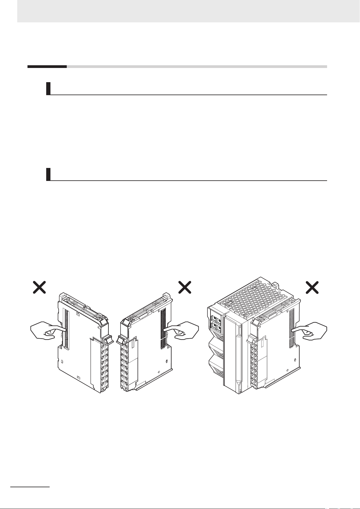
Example: NX Units (12 mm wide) Communication Control Unit
Precautions for Safe Use
Precautions for Safe Use
Transporting
• Do not attempt to disassemble, repair, or modify any Units. Doing so may result in malfunction or
fire.
• Do not drop any Unit or subject it to abnormal vibration or shock. Doing so may result in Unit malfunction or burning.
• When transporting any Unit, use the special packing box for it. Also, do not subject the Unit to excessive vibration or shock during transportation.
Mounting
• Always turn OFF the power supply before mounting a Unit. If the power supply is not OFF, the Unit
may malfunction or may be damaged.
• Mount terminal blocks and connectors only after checking the mounting location carefully. Be sure
that the terminal blocks, expansion cables, and other items with locking devices are properly locked
into place.
• Do not apply labels or tape to the Unit. When the Units are installed or removed, adhesive or scraps
may adhere to the pins in the NX bus connector, which may result in malfunctions.
• Do not touch the pins in the NX bus connector on the Unit. Dirt may adhere to the pins in the NX bus
connector, which may result in malfunctions.
• Do not write on the Communication Control Unit or an NX Unit with ink within the restricted region
that is shown in the following figure. Also do not get this area dirty. When the Unit is installed or removed, ink or dirt may adhere to the pins in the NX bus connector, which may result in malfunctions
in the Controller.
28
NX-series Safety Control Unit/Communication Control Unit User's Manual (Z395)
Page 31

Restricted region
(shaded portion)
Precautions for Safe Use
• The End Cover has a metal portion and is heavier than it looks. Be careful not to drop it when handling.
Installation
• Always connect to a ground of 100 Ω or less when installing the Units.
Wiring
• Follow the instructions in this manual to correctly perform wiring.
Double-check all switch settings to make sure that they are correct before turning ON the power
•
supply.
• Use the methods that are specified in this manual for wiring the terminal blocks.
• Use crimp terminals for wiring the M3 screw terminal blocks. Do not connect bare stranded wires
directly to the M3 screw terminal blocks.
• Use the correct wiring parts and tools when you wire the system. Otherwise, cables may be disconnected to cause short-circuit or wire breakage.
• Do not pull on the cables or bend the cables beyond their natural limit. Do not place any heavy objects on the cables or other wiring lines. Doing so may severe the cables.
• When wiring or installing the Units, do not allow metal fragments to enter the Units.
• Mount terminal blocks and connectors only after checking the mounting location carefully.
• Be sure that the terminal blocks, communications cables, and other items with locking devices are
properly locked into place.
• If the external power supply to a Output Unit or slave has polarity, connect it with the correct polarity.
If the polarity is reversed, current may flow in the reverse direction and damage the connected devices regardless of the operation of the Controller.
• Do not press the flat-blade screwdriver straight into the release hole on the screwless clamping terminal block. Doing so may damage the terminal block.
NX-series Safety Control Unit/Communication Control Unit User's Manual (Z395)
29
Page 32

NG OK
NG NG
Precautions for Safe Use
• When you insert a flat-blade screwdriver into a release hole on the screwless clamping terminal
block, press the screwdriver down with a force of 30 N or less. Applying excessive force may damage the terminal block.
Do not tilt or twist the flat-blade screwdriver while it is pressed into the release hole on the screwless
•
clamping terminal block. Doing so may damage the terminal block.
Power Supply Design
• Select an external power supply with sufficient capacity by considering the power supply capacity or
inrush current when the power is turned ON that is specified in this manual.
Otherwise, the external power supply may not be turned ON or malfunction due to unstable power
supply voltage.
Use the I/O power supply current at 4 A or less. Using the currents that are outside of the specifica-
•
tions may cause failure or damage.
• Do not apply voltages or connect loads to the Output Units or slaves in excess of the rated value.
• Surge current occurs when the power supply is turned ON. When selecting fuses or breakers for
external circuits, consider the above precaution and allow sufficient margin in shut-off performance.
Refer to this manual for surge current specifications.
• If the full dielectric strength voltage is applied or turned OFF using the switch on the tester, the generated impulse voltage may damage the Power Supply Unit. Use the adjustment on the tester to
gradually increase and decrease the voltage.
• Install external breakers and take other safety measures against short-circuiting and overcurrents in
external wiring.
• Use the I/O power supply capacity within the range that is given in the Unit specifications.
• Provide suitable power supply capacity according to the reference manuals.
• Use the power supply voltage that is specified in the related manuals.
• Do not apply voltages that exceed the rated value to any Input Unit.
30
NX-series Safety Control Unit/Communication Control Unit User's Manual (Z395)
Page 33

Precautions for Safe Use
Debugging
• With forced refreshing, the values of variables are overwritten with specified values and then the
safety programs are executed. If forced refreshing is used for variables that give the results of program processing, the variables will first take the specified values, but they will then be overwritten by
the safety program.
•
Depending on the difference in the forced status, the control system may operate unexpectedly.
• After you clear the memory, the Controller operates in the same way as immediately after you create
the system configuration with the Controller in the factory default condition.
• Verify that the safety communications with a remote node will be established in the debug mode of
the Safety CPU Unit.
Turning ON the Power Supply or Restarting after Safety Validation
• Remember that if safety validation is successful, the next time the Safety CPU Unit is started, it will
automatically start in RUN mode.
•
When you download the parameters for the Communication Control Unit and NX Units, the Safety
CPU Unit automatically restarts.
Turning ON the Power Supply
• Double-check all wiring connections and switch settings to make sure that they are correct before
turning ON the power supply
• Make sure that the voltages and currents that are input to the Units and slaves are within the specified ranges. Inputting voltages or currents that are outside of the specified ranges may damage the
Units or slaves or cause fire.
• It takes approximately 20 seconds for the Communication Control Unit to start up after the power
supply is turned ON. During that time, digital outputs on the CPU Rack will be OFF. Note that the
slave outputs will behave according to the setting values.
Use the system-defined variables and the NX Unit device variables in the user program to confirm
that I/O data communications are established before attempting control operations. During the startup process, communications with external devices will not be established.
• Configure the external circuits so that the power supply to the control system turns ON only after the
power supply to the Controller has turned ON. If the power supply to the Controller is turned ON
after the control power supply, temporary errors may result in incorrect control system signals because the output terminals on Output Units may momentarily turn ON when power supply is turned
ON to the Controller.
• You cannot obtain normal input data from NX Units while the Units are restarting. Use device variables for the NX bus master of the Communication Control Unit in the user program to check the validity of the I/O data before you attempt control operations.
. Use the correct wiring parts and tools when you wire the system.
Actual Operation
• The relevant Units will maintain the safe states for I/O data with safety connections after an error is
detected in safety process data communications. However
safety process data communications will recover automatically.
NX-series Safety Control Unit/Communication Control Unit User's Manual (Z395)
, when the cause of the error is removed,
31
Page 34

Precautions for Safe Use
If you need to prevent equipment from restarting when safety process data communications recover
automatically
• If you change the fail-soft operation setting, the output status when the error occurs may also
change. Confirm safety before you change the setting.
• If you use fail-soft operation, write programming to determine whether Unit I/O data is valid. Without
such programming, the user program cannot distinguish between Units for which I/O refreshing is
continued and Units for which I/O refreshing is stopped.
, implement suitable restart conditions in the user program.
Turning OFF the Power Supply
• Never turn OFF the power supply to the Controller when the BUSY indicator is flashing. While the
BUSY indicator is lit, the settings in the Communication Control Unit are being backed up in the
built-in non-volatile memory
OFF. Also, a major fault level Controller error will occur the next time you start operation, and operation will stop.
• Do not turn OFF the power supply or remove the SD Memory Card while SD Memory Card access
is in progress (i.e., while the SD BUSY indicator flashes). Data may become corrupted, and the
Controller will not operate correctly if it uses corrupted data. To remove the SD Memory Card from
the Communication Control Unit while the power supply is ON, press the SD Memory Card power
supply switch first. Make sure that the SD BUSY Indicator and the SD PWR Indicator are turned
OFF before you remove the SD Memory Card.
• If the Unit power supply is turned OFF before the I/O power supply for the control system is turned
OFF, the output terminals of Output Units may malfunction and the control system may perform incorrect output temporarily. To avoid this problem, configure the external circuit to make sure that the
Unit power supply is turned OFF only after the power supply for the control system is turned OFF.
• Do not disconnect the cable or turn OFF the power supply to the Controller when downloading data
or the user program from Support Software.
• Always turn OFF the power supply to the Controller before you attempt any of the following.
a) Mounting or removing an NX Unit, Communication Control Unit
b) Assembling Units
c) Setting DIP switches or rotary switches
d) Connecting or wiring cables
e) Attaching or removing terminal blocks or connectors
The Power Supply Unit may continue to supply power to the Controller for a few seconds after the
power supply turns OFF. The UNIT PWR and I/O PWR indicators are lit during this time. Confirm
that the UNIT PWR and the I/O PWR indicators are not lit before you perform any of the above actions.
. This data will not be backed up correctly if the power supply is turned
32
Operation
• Confirm that no adverse effect will occur in the system before you attempt any of the following.
a) Changing the operating mode of the Safety CPU Unit
b) Changing the user program or settings
c) Changing set values or present values
d) Forced refreshing
e) Restarting a slave or Unit after you change any settings
NX-series Safety Control Unit/Communication Control Unit User's Manual (Z395)
Page 35

Precautions for Safe Use
f) Transferring a backup file on the SD Memory Card
•
After you change any slave or Unit settings, carefully check the safety of the controlled system before you restart the Unit.
• If two different function modules are used together, such as when you use an EtherNet/IP Function
Module and an NX Bus Function Module, take suitable measures in the user program and external
controls to ensure that safety is maintained in the controlled system if one of the function modules
stops. The relevant outputs will behave according to the slave or Unit specifications if a partial fault
level error occurs in one of the function modules.
General Communications
• When you use data link communications, check the error information that is given in _ErrSta (Controller Error Status) to make sure that no error has occurred in the source device. Create a user program that uses reception data only when there is no error in the source device.
If there is an error in the source device, the data for the data link may contain incorrect values.
•
If an error occurs in tag data link communications or communications between NX Units, this product continues refreshing variables with the last values that it receives.
• Unexpected operation may result if inappropriate data link tables are set. Even if appropriate data
link tables have been set, confirm that the controlled system will not be adversely affected before
you transfer the data link tables. The data links start automatically after the data link tables are
transferred.
EtherNet/IP Communications
• Before using I/O data, confirm that this product serves your purpose, in consideration of the following specifications of tag data link communications for this product.
a) If an error occurs in tag data link communications, this product continues refreshing variables
with the last values that it receives.
b) If an error occurs in tag data link communications, the Omron EtherNet/IP Originator automati-
cally restores the communications after resolving the cause of the error
c) This product cannot monitor the target connection status. If you use this product as a target de-
vice, make sure to use the originator to check the connection status.
• Make sure to use the communications distance, number of nodes connected, and method of connection for EtherNet/IP within specifications. Do not connect EtherNet/IP communications to EtherCAT or other networks. An overload may cause the network to fail or malfunction.
• All related EtherNet/IP nodes are reset when you transfer settings for the built-in EtherNet/IP port
(including IP addresses and tag data links settings). The settings can only be enabled after the reset. Confirm that the system will not be adversely affected by resetting nodes before you transfer the
settings.
• If EtherNet/IP tag data links (cyclic communications) are used with a repeating hub, the communications load on the network will increase. This will increase collisions and may prevent stable communications. Do not use repeating hubs on networks where tag data links are used. Use an Ethernet
switch instead.
.
NX-series Safety Control Unit/Communication Control Unit User's Manual (Z395)
33
Page 36

Precautions for Safe Use
Restoring Data
• You cannot back up, restore, or compare some or all of the settings for certain slaves and Units.
Also, you cannot back up, restore, or compare data for disabled slaves or Units. After you restore
data, suf
ficiently confirm that operation is correct before you start actual operation.
Transferring Programs
• Always confirm safety at the connected equipment before you perform the download when the device output hold configuration is set to enable. The equipment may operate unexpectedly because
the last status for outputs is retained.
Standards
• The customer is responsible for attaining conformance of the entire system to standards.
Maintenance
• Test the functionality every six months to detect welded contactor contacts.
T
o detect electrical and mechanical failures, use a combination of redundant semiconductor output
contacts and redundant mechanical output devices.
Unit Replacement
• Make sure that the required data, including the configurations, settings and variables, is transferred
to a Communication Control Unit that was replaced and to externally connected devices before restarting operation. Be sure to transfer the tag data link settings and routing tables, which are stored
in the Communication Control Unit.
•
After you replace the Safety Control Unit, set the program and all configuration settings that are necessary to resume operation. Make sure that the safety functions operate normally before you start
actual operation.
• When you replace a Unit, start operation only after you transfer the settings and variables that are
required for operation to the new Unit.
Disposal
34
• Dispose of the product according to local ordinances as they apply.
NX-series Safety Control Unit/Communication Control Unit User's Manual (Z395)
Page 37

Precautions for Correct Use
Storage and Installation
• Follow the instructions in this manual to correctly perform installation and wiring.
• Do not operate or store the Units in the following locations. Doing so may result in burning, in operation stopping, or in malfunction.
a) Locations subject to direct sunlight
b) Locations subject to temperatures or humidity outside the range specified in the specifications
c) Locations subject to condensation as the result of severe changes in temperature
d) Locations subject to corrosive or flammable gases
e) Locations subject to dust (especially iron dust) or salts
f) Locations subject to exposure to water, oil, or chemicals
g) Locations subject to shock or vibration
h) Locations subject to static electricity or other forms of noise
• Take appropriate and sufficient countermeasures when installing the Controller in the following locations.
a) Locations subject to strong, high-frequency noise
b) Locations subject to static electricity or other forms of noise
c) Locations subject to strong electromagnetic fields
d) Locations subject to possible exposure to radioactivity
e) Locations close to power lines
• Before touching a Unit, be sure to first touch a grounded metallic object in order to discharge any
static build-up.
• Use the rated power supply voltage for the Units that supply power. Take appropriate measures to
ensure that the specified power with the rated voltage and frequency is supplied in places where the
power supply is unstable.
• Install the Units in a well-ventilated area. Avoid installing the Units near heating elements. Doing so
may result in malfunction, in operation stopping, or in burning.
Precautions for Correct Use
Mounting
• When you install the Unit, be careful not to touch or bump the pins in the NX bus connector.
• When you handle the Unit, be careful not to apply stress to the pins in the NX bus connector.
If the Unit is installed and the power supply is turned ON when the pins in the NX bus connector are
deformed, contact failure may cause malfunctions.
• Always mount an End Cover to the end of the CPU Rack to protect the last Unit on the CPU Rack.
Not mounting the End Cover may result in malfunction or failure of the Units.
• After you mount the Unit, always secure it with End Plates at both sides. If you do not secure it, the
Unit may be damaged or malfunction.
• If you use DIN Track Insulation Spacers to install a CPU Rack, the height will be increased by approximately 10 mm. Make sure that the CPU Rack and connecting cables do not come into contact
with other devices.
• To remove an NX Unit, remove multiple NX Units together including the one you need to remove. If
you attempt to remove only one NX Unit, it may be tight and difficult to pull out. Do not unlock the
NX-series Safety Control Unit/Communication Control Unit User's Manual (Z395)
35
Page 38

Precautions for Correct Use
DIN Track mounting hooks on all of the NX Units at the same time. If you unlock the DIN Track
mounting hooks on all of the NX Units at the same time, all of the Units may come of
Wiring
• Do not allow foreign matter to enter the openings in the Unit. Doing so may result in Unit burning,
electric shock, or failure.
•
Do not allow wire clippings, shavings, or other foreign material to enter any Unit. Otherwise, Unit
burning, failure, or malfunction may occur. Cover the Units or take other suitable countermeasures,
especially during wiring work.
• For EtherNet/IP, use the connection methods and cables that are specified in this manual. Otherwise, communications may be faulty.
• Use the rated power supply voltage for the Units that supply power. Take appropriate measures to
ensure that the specified power with the rated voltage and frequency is supplied in places where the
power supply is unstable.
• Make sure that the current capacity of the wire is sufficient. Otherwise, excessive heat may be generated. When cross-wiring terminals, the total current for all the terminals will flow in the wire. When
wiring cross-overs, make sure that the current capacity of each of the wires is not exceeded.
• If you use reed switches for the input contacts for AC Input Units, use switches with a current capacity of 1 A or greater.
If reed switches with smaller allowable currents are used, the contacts may fuse due to surge currents.
f.
Operation
• Confirm the Device Output Hold Configuration before you download data from the Communication
Control Unit.
•
Take safety measures for the controlled system as well.
EtherNet/IP Communications
• To set up an intranet through a global address involves network security considerations. Be sure to
consult with a network specialist in advance and consider installation of a firewall.
After a firewall is set up by a communications technician, there may be some applications that cannot be used. Be sure to check first with the communications technician.
Error Processing
• If you change the event level of a Controller error, the output status when the error occurs may also
change. Confirm safety before use.
36
Restoring Data
• When you edit the restore command file or the automatic transfer command file, do not change anything in the file except for the “yes” and “no” specifications for the selectable data groups. If you
NX-series Safety Control Unit/Communication Control Unit User's Manual (Z395)
Page 39

Precautions for Correct Use
change anything else in the file, the Controller may perform unexpected operation when you restore
or automatically transfer the data.
•
To prevent an unexpected restoration, set to enter the password for each execution before the restore operation.
Actual Operation
• Make sure that you are connected to the correct Safety CPU Unit before you perform any online operations with the Safety CPU Unit.
•
Before you transfer safety application data to the Safety CPU Unit, check the safety signature and
make sure the data is the intended data.
• Always confirm the destination before you transfer configuration information and safety application
data from the Sysmac Studio.
• You cannot monitor or perform certain online operations with the same Safety CPU Unit from more
than one copy of the Sysmac Studio at the same time.
Turning OFF the Power Supply
• Do not turn OFF the power supply while data is being transferred.
Debugging
• The task period affects the safety response performance. If the task period changes due to changes
in the configuration or programs, recalculate the safety reaction times.
•
If you change the I/O for a variable to publish to a Communication Control Unit, the device variable
assignments to the Communication Control Unit will be canceled. In this case, you need to assign
the device variables, and then transfer the settings and programs to the Communication Control
Unit. After you transfer the settings and programs, check that the operation of the Communication
Control Unit is correct.
• For security purposes, we recommend that you set a password for the Safety CPU Unit and the
project file. To avoid the leakage, keep the passwords under strict control. Especially, when you
transmit password data through the Internet, implement a measure to secure the transmission such
as by using the public key encryption.
• If you lose the password that is set to the Safety CPU Unit, you will no longer be able to make
changes to the Safety CPU Unit. Take caution not to lose the password. If you want to reset the configured password, contact your OMRON representative.
• For safety data logging, make sure to use the settings file generated from the same project file as
the logging target.
SD Memory Cards
• Insert the SD Memory Card all the way.
•
Do not turn OFF the power supply to the Controller during SD Memory Card access. The files may
be corrupted.
NX-series Safety Control Unit/Communication Control Unit User's Manual (Z395)
37
Page 40

Precautions for Correct Use
If there is a corrupted file in the SD Memory Card, the file is automatically deleted by the restoration
function when the power supply is turned ON.
•
If you use an OMRON SD Memory Card, the end of the life of the SD Memory Card can be detected
in the following ways.
a) _Card1Deteriorated (SD Memory Card Life Warning Flag) system-defined variable
b) SD Memory Card Life Exceeded event in the event log
When the end of the life is detected in any of the above ways, replace the SD Memory Card.
Replacing Slaves and Units
• If you replace a slave or Unit, refer to the operation manual for the slave or Unit for information on
the data required for individual slaves or Units and redo the necessary settings.
Periodic Inspections and Maintenance
• Do not disassemble, repair, or modify the Safety Control Unit. Doing so may lead to loss of safety
functions.
Disposal
• Be careful not to injure yourself when dismantling the Safety Control Unit.
38
NX-series Safety Control Unit/Communication Control Unit User's Manual (Z395)
Page 41

Regulations and Standards
The NX-series Safety Control Units are certified for the following standards.
• Safety CPU Unit NX-SL5500 / NX-SL5700
Regulations and Standards
Certification
body
TÜV Rheinland
• EN ISO 13849-1: 2015
• EN ISO 13849-2: 2012
*1
• IEC 61508 parts 1-7: 2010
Standards
• IEC 61326-3-1: 2017
• IEC 61131-6: 2012
• IEC/EN 62061:2005+A1: 2013+A2:2015
• IEC/EN 61
UL NRAG (UL61010-1, UL61010-2-201, and UL121201)
NRAG7 (CSA C22.2 No.61010-1, CSA C22.2 No.61010-2-201, and CSA C22.2 No.213)
FSPC (IEC 61508 and ISO 13849)
*1. The FSoE protocol was certified for applications in which OMRON FSoE devices are connected to each
.
other
For compatibility with FSoE devices other than OMRON FSoE devices, the customer must validate FSoE
communications.
131-2: 2007
• Safety I/O Unit NX-SID800 / NX-SIH400 / NX-SOD400 / NX-SOH200
Certification body Standards
• EN ISO 13849-1: 2015
• IEC 61326-3-1: 2017
• EN ISO 13849-2: 2012
*1
TÜV Rheinland
• IEC 61508 parts 1-7: 2010
• IEC/EN 62061 : 2005+A1: 2013+A2:2015
• IEC/EN 61
UL NRAG (UL508 and ANSI/ISA 12.12.01)
NRAG7 (CSA C22.2 No.142 and CSA C22.2 No.213)
*1. The FSoE protocol was certified for applications in which OMRON FSoE devices are connected to each
.
other
For compatibility with FSoE devices other than OMRON FSoE devices, the customer must validate FSoE
communications.
131-2: 2007
The NX-series Safety Control Units allow you to build a safety control system that meets the following
standards.
•
Requirements for SIL 3 (Safety Integrity Level 3) in IEC 61508, IEC/EN 62061, (Functional Safety of
Electrical/Electronic/Programmable Electronic Safety-related Systems)
• Requirements for PLe (Performance Level e) and for safety category 4 in EN ISO13849-1
The NX-series Safety Control Units are also registered for RCM, EAC, and KC compliance.
The NX-series Communication Control Units are certified for the following standards.
Certification body Standards
UL NRAG (UL61010-1, UL61010-2-201, and UL121201)
NRAG7 (CSA C22.2 No.61010-1, CSA C22.2 No.61010-2-201, and CSA C22.2 No.213)
The NX-series Communication Control Units are also registered for RCM, EAC, and KC compliance.
Conformance to EU Directives
NX-series Safety Control Unit/Communication Control Unit User's Manual (Z395)
39
Page 42

Regulations and Standards
Applicable Directives
• EMC Directives
•
Machinery Directive
Concepts
EMC Directives
l
OMRON devices that comply with EU Directives also conform to the related EMC standards so that
they can be more easily built into other devices or the overall machine. The actual products have
been checked for conformity to EMC standards.*1
Whether the products conform to the standards in the system used by the customer
be checked by the customer. EMC-related performance of the OMRON devices that comply with
EU Directives will vary depending on the configuration, wiring, and other conditions of the equipment or control panel on which the OMRON devices are installed. The customer must, therefore,
perform the final check to confirm that devices and the overall machine conform to EMC standards.
*1. Applicable EMC (Electromagnetic Compatibility) standards are as follows: EMS (Electromagnetic Suscept-
ibility): EN 61
tions).
131-2 EMI (Electromagnetic Interference): EN 61131-2 (Radiated emission: 10-m regula-
, however, must
Machinery Directive
l
The Machinery Directive requires ensuring the required safety for safety components used for machinery safety
Applicable standards: EN ISO 13849-1 and IEC/EN 62061.
Conformance to EU Directives
l
The NX-series Units comply with EU Directives. To ensure that the machine or device in which the
NX-series Units are used complies with EU Directives, the following precautions must be observed.
• The NX-series Units must be installed within a metallic control cabinet.
• You must meet the following conditions for the DC power supplies that are connected as the Unit
power supplies and I/O power supplies for the NX-series Units.
a) Use reinforced insulation or double insulation.
b) Ensure an output hold time of 20 ms min.
c) Use an SELV power supply that meets the requirements of IEC/EN 60950-1 and EN 50178.
Do not allow the power supply cable length to exceed 3 m.
We recommend that you use the OMRON S8VK-S-series Power Supplies. EMC standard compliance was confirmed for the recommended Power Supplies.
• NX-series Units that comply with EU Directives also conform to the Common Emission Standard.
Radiated emission characteristics (10-m regulations) may vary depending on the configuration of
the control panel used, other devices connected to the control panel, wiring, and other conditions.
You must therefore confirm that the overall machine or equipment in which the NX-series Units
are used complies with EU Directives.
• This is a Class A product (for industrial environments). In a residential environment, it may cause
radio interference. If radio interference occurs, the user may be required to take appropriate
measures.
.
40
NX-series Safety Control Unit/Communication Control Unit User's Manual (Z395)
Page 43

Conformance to EN ISO 13849-1 and IEC/EN 62061
EN ISO 13849-1 and IEC/EN 62061 require functional safety management to avoid systematic failure
during the software development. This is required in all phases of the life cycle of software programming and software design (e.g., basic software design, safety circuit system design, and software upgrades) in safety control systems to be developed using safety controllers.
Therefore, functional safety management is required for design and development of software for facilities and equipment that use the function blocks provided in the Safety Controller
The customer must implement measures to ensure compliance with these standards.
You can download the reliability data for safety of machinery that is required to verify the safety performance of your equipment from the following URL: http://www.ia.omron.com/support/sistemalibrary/
index.html.
Conformance to UL and CSA Standards
The NX-series Safety Control Units comply with the following UL and CSA standards. The application
conditions for standard compliance are defined. Refer to the Instruction Sheet that is provided with
each Unit before application.
Regulations and Standards
.
Conformance to Shipbuilding Standards
Some NX-series products comply with shipbuilding standards. If you use an NX-series product that
complies with shipbuilding standards and the machinery or system in which you use the NX-series
product must also comply with the standards, consult with your OMRON representative. Application
conditions are defined according to the installation location. Application may not be possible for some
installation locations.
Usage Conditions for NK and LR Shipbuilding Standards
• A Safety Control Unit must be installed within a control panel.
•
Gaps in the door to the control panel must be completely filled or covered with gaskets or other material.
• The following noise filter must be connected to the power supply line.
Noise Filter
Name Manufacturer Model
Noise filter Cosel Co., Ltd. TAH-06-683
Conformance to KC Certification
When you use this product in South Korea, observe the following precautions.
NX-series Safety Control Unit/Communication Control Unit User's Manual (Z395)
41
Page 44

Regulations and Standards
This product meets the electromagnetic compatibility requirements for business use. There is a risk of
radio interference when this product is used in home.
Usage Conditions for KC Certification
Take the same measures as those described in Conformance to EU Directives on page 39
tion, attach a clamp core to the port side of the EtherNet/IP cable.
The recommended clamp core is given below.
Recommended Clamp Core
Manufacturer Product Model Turns of cable
NEC TOKIN Clamp core ESD-SR-250 1 turn
. In addi-
42
NX-series Safety Control Unit/Communication Control Unit User's Manual (Z395)
Page 45

Unit Versions
(A)
(B)
PORT1
: ££££££££££££
PORT2 : ££££££££££££
Ver.1.££ HW Rev. £
LOT No. DDMYY£ xxxx
(C)
(D)
ID Information Indication
This section describes the notation that is used for unit versions, the confirmation method for unit versions, and the relationship between unit versions and Sysmac Studio versions.
Unit Versions
A “unit version” has been introduced to manage the Communication Control Unit and the Safety Control Unit according to differences in functionality accompanying Unit upgrades.
Notation of Unit Versions on Products
The unit version is given with the Unit specifications on the side of the Unit or in the notched area.
Unit Versions
Communication Control Unit
l
ID Information is given with the ID information indication on the side of the Unit.
Letter Name Function
A Lot number and serial num-
ber
B Unit version Gives the unit version of the Unit.
C MAC addresses Gives the MAC addresses of the built-in EtherNet/IP port (port 1) and the built-
D Hardware revision
*1. The hardware revision is not displayed for the Unit that the hardware revision is in blank.
Gives the lot number and the serial number of the Unit.
: Lot number, £: Used by OMRON, SSSS: Serial number
DDMYY
“M” gives the month (1 to 9: January to September, X: October, Y: November,
Z: December)
in EtherNet/IP port (port 2) on the Unit.
Gives the hardware revision of the Unit.
*1
NX Units
l
The unit version is given with the Unit specifications on the side of the Unit or in the notched area.
NX-series Safety Control Unit/Communication Control Unit User's Manual (Z395)
43
Page 46

Notched
area
Unit
specifications
LOT No.
Lot number and unit version Unit model number
Unit versionLot number
Unit Versions
The following information is provided in the Unit specifications on the Unit.
Name Function
Unit model number Gives the model of the Unit.
Unit version Shows the unit version of the Unit.
Lot number Gives the lot number of the Unit.
The following information is provided in the notched area on the Unit.
44
DDMYY£: Lot number
“M” gives the month (1 to 9: January to September, X: October, Y: November,
Z: December)
NX-series Safety Control Unit/Communication Control Unit User's Manual (Z395)
, £: Used by OMRON.
Page 47

Unit Versions
Name Function
Lot number and unit version
Gives the lot number and unit version of the Unit.
• DDMYY£: Lot number
“M” gives the month (1 to 9: January to September, X: October, Y: November, Z: December)
• 1£: Unit version
The decimal portion of the unit version is omitted. (It is provided in the Unit
specifications.)
, £: Used by OMRON.
Checking Unit Versions with the Sysmac Studio
You can check unit versions with the Sysmac Studio.
Checking the Unit Version of a Communication Control Unit
l
You can use the Production Information while the Sysmac Studio is online to check the unit version
of a Unit. You can do this for the Communication Control Unit, NX Units on the CPU Rack.
1 Right-click CPU Rack under Configurations and Setup - CPU/Expansion Racks in the Multi-
view Explorer and select Display Production Information.
The Production Information Dialog Box is displayed.
Changing Information Displayed in Production Information Dialog Box
l
1 Click the Show Detail or Show Outline Button at the lower right of the Production Information
Dialog Box.
The view will change between the production information details and outline.
Outline View Detail View
The information that is displayed is different for the Outline View and Detail View. The Detail
V
iew displays the unit version, hardware revision, and various versions. The Outline View dis-
plays only the unit version.
Note The hardware revision is separated by "/" and displayed on the right of the hardware version. The
hardware revision is not displayed for the Unit that the hardware revision is in blank.
Unit Versions of Units and Sysmac Studio Versions
The functions that are supported depend on the unit version of the Unit. The version of Sysmac Studio
that supports the functions that were added for an upgrade is also required to use those functions.
o use the NX-CSG£££ Communication Control Unit and the NX-SL5£££ Safety CPU Unit, Sys-
T
mac Studio version 1.24 or higher is required.
NX-series Safety Control Unit/Communication Control Unit User's Manual (Z395)
45
Page 48

Unit Versions
Refer to A-18 V
Units and the Sysmac Studio versions, and for the functions that are supported by each unit version.
ersion Information on page A-109 for the relationship between the unit versions of the
46
NX-series Safety Control Unit/Communication Control Unit User's Manual (Z395)
Page 49

Related Manuals
The followings are the manuals related. Use these manuals for reference.
Manual name Cat. No. Model numbers Application Description
NX-series
Safety Control Unit / Communication Control Unit
User
’s Manual
NX-series
Communication Control Unit
Built-in Function
’s Manual
User
GI-S Series
Safety I/O T
User's Manual
NX-series
Safety Control Unit
Instructions Reference Manual
NX-series
Digital I/O Units
User
NX-series
Analog I/O Units
User
for Analog Input Units and
Analog Output Units
NX-series
Analog I/O Units
User
for Temperature Input Units
and Heater Burnout Detection Units
NX-series
Data Reference Manual
Sysmac Studio Version 1
Operation Manual
NX-series
System Units
User
erminal
’s Manual
’s Manual
’s Manual
’s Manual
Z395
Z396
Z400
Z931
W521
W522
W566
W525
W504 SYSMAC
W523
NX-SL5£££
NX-SI££££
NX-SO££££
NX-CSG£££
NX-CSG£££
GI-S££££££
NX-SL££££
NX-ID££££
NX-IA££££
NX-OC££££
NX-OD££££
NX-MD££££
NX-AD££££
NX-DA££££
NX-TS££££
NX-HB££££
NX-££££££
-SE2£££
NX-PD1£££
NX-PF0£££
NX-PC0£££
NX-TB£££X
Learning how to use
the NX-series Safety
Control Units and
Communication Control Units.
Learning about the
built-in functions of
an NX-series Communication Control
Unit.
Learning how to use
the GI-S Series Safety I/O Terminals.
Learning about the
specifications of instructions for the
Safety CPU Unit.
Learning how to use
NX-series Digital I/O
Units.
Learning how to use
NX-series Analog Input Units and Analog
Output Units.
Learning how to use
NX-series Temperature Input Units and
Heater Burnout Detection Units.
Referencing lists of
the data that is required to configure
systems with NX-series Units.
Learning about the
operating procedures
and functions of the
Sysmac Studio.
Learning how to use
NX-series System
Units
Related Manuals
Describes the hardware, setup methods,
and functions of the NX-series Safety Control Units and Communication Control
Units.
Describes the software setup methods and
communicantions functions of an NX-series Communication Control Unit.
Describes the hardware, setup methods,
and functions of the GI-S Series Safety I/O
Terminals.
Describes the instructions for the Safety
CPU Unit.
The hardware, setup methods, and functions of the NX-series Digital I/O Units are
described.
The hardware, setup methods, and functions of the NX-series Analog Input Units
and Analog Output Units are described.
The hardware, setup methods, and functions of the NX-series Temperature Input
Units and Heater Burnout Detection Units
are described.
Lists of the power consumptions, weights,
and other NX Unit data that is required to
configure systems with NX-series Units are
provided.
Describes the operating procedures of the
Sysmac Studio.
The hardware and functions of the NX-series System Units are described.
NX-series Safety Control Unit/Communication Control Unit User's Manual (Z395)
47
Page 50

Terminology
Terminology
Term Description
standard The generic term for devices, functions, and data that are used for general control purposes
as opposed to those that are used for safety measures.
safety function A function that is executed by the safety control system to achieve a safe state for a machine
hazard.
safe state The status of a device or piece of equipment when the risk of danger to humans has been
reduced to an acceptable level.
safety signal A signal that is used for safety controls.
In this safety control system, the data type of a variable determines whether a signal is related to the safety controls. Broadly speaking, there are two data types: safety data types and
standard data types.
standard signal A signal or data that is used for general control purposes.
Safety data type The data type for a safety signal.
Standard data type The data type for a standard signal.
safety reaction time The time required for the system to enter a safe state in a worst-case scenario after the oc-
currence of a safety-related input (press of an emergency stop pushbutton switch, interrup-
tion of a light curtain, opening of a safety door
The reaction time of the system includes the reaction times of sensors and actuators, just
like the reaction time for a Controller or network.
safety control A type of control that uses devices, functions, and data that are designed with special safety
measures.
standard control A type of control that use devices, functions, and data that are designed for general control
purposes. This term is used to dif
safety process data communications A type of I/O data communications that is used for safety control purposes.
standard process data communications A type of I/O data communications that is used for standard control purposes.
Safety I/O connection A type of connections that is used for safety process data communications.
CIP Safety connection Safety I/O connection that is used to transmit safety process data by the communication pro-
tocol called CIP Safety
are available depending on the roles of communications.
CIP Safety originator connection A CIP Safety connection when an own node is a CIP Safety originator.
CIP Safety target connection A CIP Safety connection when an own node is a CIP Safety target.
CIP Safety originator A role in CIP Safety communications. A CIP Safety originator manages a CIP Safety connec-
tion for a CIP Safety target. CIP Safety originator exists in a connection unit, and not in a
device unit.
CIP Safety target A role in CIP Safety communications. A CIP Safety target receives a request to open a CIP
Safety connection from a CIP Safety originator
and not in a device unit.
single-cast connection A safety process data communications method in CIP Safety. A CIP Safety originator and a
CIP Safety target communicate one-to-one in this connection.
ou can apply this setting for both of input data and output data.
Y
multi-cast connection A safety process data communications method in CIP Safety. A CIP Safety target sends the
input data of the CIP Safety target in multi-cast to multiple CIP Safety originators in this con-
nection.
This is a connection type you can set only for input data of a CIP Safety target. Y
apply this setting for output data.
FSoE master connection Master safety I/O connection that is used to transmit safety process data by the communica-
tion protocol called FSoE.
safety master connection The generic term for the CIP Safety originator connection and the FSoE master connection.
exposing global variables to the Commu-
nication Control Unit
Safety Control Unit The generic term for a Unit that is used in safety controls.
Safety CPU Unit A CPU Unit that is used for safety controls. This is a type of NX Unit.
Exposing specified global variables to the Communication Control Unit to allow the exchange
of standard signals between the standard controller and the Safety CPU Unit.
Exposed variables can be transmitted to the standard controller via tag data links.
. CIP Safety originator connection and CIP Safety target connection
ferentiate from a safety control
, etc.) or device failure.
. CIP Safety target exists in a connection unit,
ou cannot
48
NX-series Safety Control Unit/Communication Control Unit User's Manual (Z395)
Page 51

Terminology
Term Description
Safety I/O Unit An I/O Unit that is used for safety controls. This is a type of NX Unit.
safety input device An input device that is designed with special safety measures for use in safety controls.
The generic term for safety input devices, such as emergency stop pushbutton switches and
safety switches.
safety output device An output device that is designed with special safety measures for use in safety controls.
The generic term for safety output devices, such as safety relays.
EtherNet/IP Slave Terminal An EtherNet/IP Slave Unit Terminal is a building-block slave that is created by mounting a
group of NX Units.
Communication Control Unit The generic term for the interface units to have CIP Safety communications on a network be-
tween the Safety CPU Unit and CIP Safety on EtherNet/IP devices.
Safety Network Controller The generic term for the building-block type safety controllers that have mounted the Safety
Control Unit with the Communication Control Unit.
Safety program User programming for safety controls in the Safety CPU Unit.
This term is used to dif
Safety programs are programmed in the FBD language.
FBD language The abbreviation for the function block diagram programming language. This is a graphical
language used to program algorithms with connecting lines that represent the flow of inputs
and data, and rectangular boxes that represent functions or function blocks.
Unlike the ladder diagram language, the FBD language does not have bus bars, and the
connecting lines represent the flow of inputs and data rather than the power flow
Algorithms are executed in order from top to bottom in units that are called networks. A network consists of configuration elements that use connecting lines to connect inputs to outputs. The FBD language does not have an END instruction. Execution for the task period
ends when the last network is executed.
You use the FBD language to write safety programs for the Safety CPU Unit.
user program All of the programs that are created by the user. User program refers to the programs for
standard controls of the standard controller and the safety program of the Safety CPU Unit.
operating mode The status of the Safety CPU Unit, when it is in normal operation, that the user changes to
run or check the operation of the Safety CPU Unit.
There are the three modes: PROGRAM mode, DEBUG mode, and RUN mode.
ou can use DEBUG mode only when the Sysmac Studio is online with the Safety CPU Unit.
Y
safety validation The process of appending confirmation information to the safety application data if safety val-
idation testing demonstrates that the safety controls meet the required specifications of a
safety system.
ou execute the safety validation from the Sysmac Studio when the Safety CPU Unit is in
Y
DEBUG mode. The validated safety programs are automatically transferred to the non-volatile memory of the Safety CPU Unit.
DEBUG mode The mode that is used to debug unvalidated safety programs. DEBUG mode is only available
when the Sysmac Studio is online with the Safety CPU Unit.
Use this mode to check that the safety programs and external devices operate correctly
ter you confirm that the system meets the required specifications, perform the safety validation. This will enable you to change to RUN mode.
When you change from PROGRAM mode to DEBUG mode, the unvalidated safety programs
are automatically transferred to the main memory of the Safety CPU Unit.
DEBUG mode (RUN) A status that indicates that an unvalidated safety program is in execution in DEBUG mode.
ou can control BOOL variables, use forced refreshing, and change present values.
Y
DEBUG mode (STOPPED) A status that indicates that an unvalidated safety program is stopped in DEBUG mode. You
can control BOOL variables, use forced refreshing, and change present values.
PROGRAM mode A mode indicates that execution of the safety program is stopped. You cannot control BOOL
variables, use forced refreshing, or change present values.
RUN mode A mode that indicates that execution of the validated safety programs is in progress. Unlike
DEBUG mode (RUN), the validated safety programs in the non-volatile memory of the Safety
CPU Unit are executed. Y
change present values.
before safety validation A status that indicates that safety validation has not been performed on the safety applica-
tion data from the Sysmac Studio because it has not yet been determined whether the safety
controls meet the required specifications of the safety system.
ferentiate from the user program of the standard controller.
.
. Af-
ou cannot control BOOL variables, use forced refreshing, or
NX-series Safety Control Unit/Communication Control Unit User's Manual (Z395)
49
Page 52

Terminology
Term Description
after safety validation A status indicates that safety validation has been performed on the safety application data
from the Sysmac Studio because it has been determined that the safety controls meet the
required specifications of the safety system.
CPU Rack A Rack to which a CPU Unit or Communication Control Unit is mounted. For NX-series CPU
Units to which NX Units can be connected, a CPU Rack has a CPU Unit with NX Units and
an End Cover mounted to it. For NX-series Communication Control Units, a CPU Rack has a
Communication Control Unit with NX Units and an End Cover mounted to it.
CPU Rack settings It consists of the following data:
• Configuration information
• Unit operation settings
• Unit application data
configuration information It consists of the following data:
• Unit configuration information
• I/O allocation information
I/O allocation information The set of information that specifies the I/O data to be processed by I/O refreshing.
On the Sysmac Studio, this is shown as configuration information and includes the Unit con-
figuration information.
Unit configuration information The set of information that specifies the configuration of the NX Units that are connected to
the NX bus master
On the Sysmac Studio, this is shown as configuration information and includes the I/O allo-
cation information.
safety application data The data that contains the settings that are used to operate the NX-series Safety Control
Units.
It consists of the safety programs, safety task, and variables. Y
create this data, and then transfer and execute it on the Safety CPU Unit.
On the Sysmac Studio, this data is shown as the slave parameters.
The location where the safety application data is stored on the Safety CPU Unit depends on
whether the safety programs have been validated. (Unvalidated safety programs are stored
in the main memory, while validated safety programs are stored in the non-volatile memory.)
safety input function A function that evaluates whether the signals that are input on a safety input terminal are
normal or abnormal.
Specific safety evaluation functions include test pulse evaluation and dual channel evalua-
tion.
When the evaluation result shows an abnormality
(OFF).
safety output function A function that evaluates whether the values of safety output data and the output signals on
safety output terminals are normal or abnormal.
Specific safety evaluation functions include test pulse evaluation and dual channel evalua-
tion.
When the evaluation result shows an abnormality
minal is turned OFF.
dual channel evaluation This function uses a pair of safety input or safety output terminals as redundant terminals
that are checked for consistency to evaluate the status of the safety input or safety output.
single channel The input or output is used as a single point.
dual channels Two inputs or outputs are used as a pair of points for redundancy.
test pulse evaluation This function outputs a test pulse that is used to evaluate a safety input or safety output for
failures or wiring errors with the connected external device.
change tracking A pin is used to manage whether the safety application data has been changed after the fi-
nalized data is created.
UNID An ID assigned to a device so that it can be uniquely identified by all the networks on the
safety system for CIP Safety communications. An UNITD is a 10-byte value, consisting of a
6-byte Safety Network Number and a 4-byte Node ID.
Safety Network Number (SNN) A number assigned to a safety network so that it can be uniquely identified for CIP Safety
communications. The Safety Network Number is set for the NX bus, the built-in EtherNet/IP
ports 1 and 2.
.
ou use the Sysmac Studio to
, the safety input data is made inactive
, the output signal on the safety output ter-
50
NX-series Safety Control Unit/Communication Control Unit User's Manual (Z395)
Page 53

Terminology
Term Description
Node ID An ID assigned to each of devices on a network so that the devices with the same Safety
Network Number (SNN) can be uniquely identified for CIP Safety communications.
The Safety CPU Unit is the only CIP Safety device on the NX bus, and the Node ID is always
1. For a CIP Safety device on an EtherNet/IP network, its IP address is used as the Node ID.
NX-series Safety Control Unit/Communication Control Unit User's Manual (Z395)
51
Page 54

Z395-E1-09Cat. No.
R
evision code
Revision History
Revision History
A manual revision code appears as a suffix to the catalog number on the front and back covers of the
manual.
Revision
code
01 April 2018 Original production
02 July 2018
03 August 2018 Added PFH values.
04 October 2018
05 April 2019
06 July 2019
07 January 2020
08 April 2020
09 July 2020
Date Revised content
• Made changes accompanying the upgrade to NX-SL5700 unit version 1.3.
• Made revisions accompanying with addition of the NX-SL5500.
• Made revisions accompanying the upgrade to Sysmac Studio version 1.24.
• Made revisions accompanying the appearance change of the indicators.
• Corrected mistakes.
• Made revisions accompanying the appearance change of the indicators.
• Modified the model of the recommended communication cables.
• Made revisions accompanying the upgrade to Sysmac Studio version 1.27.
• Added the Shipbuilding Standards (Class NK, LR)
• Corrected mistakes.
• Made revisions accompanying the upgrade to Sysmac Studio version 1.29.
• Corrected mistakes.
• Made revisions accompanying the upgrade to Sysmac Studio version 1.31.
• Corrected mistakes.
• Made changes accompanying the upgrade to
version 1.4.
• Made revisions accompanying the upgrade to Sysmac Studio version 1.40.
• Corrected mistakes.
• Made revisions accompanying the upgrade to Sysmac Studio version 1.41.
• Corrected mistakes.
NX-SL5500/NX-SL5700 unit
52
NX-series Safety Control Unit/Communication Control Unit User's Manual (Z395)
Page 55

Overview
This section describes the overview of Safety Network Controller.
1-1
1-2 Procedure ....................................................................................................... 1-7
1
Overview of the Safety Network Controller .................................................1-2
1-1-1 Features .......................................................................................................... 1-2
1-1-2 Introduction to the System Configurations ...................................................... 1-4
1-2-1 Overall Procedure ........................................................................................... 1-7
1-2-2 Detailed Procedures........................................................................................ 1-8
1
NX-series Safety Control Unit/Communication Control Unit User's Manual (Z395)
1-1
Page 56

EtherNet/IP
Safety I/O terminal
Standard Controller
LAN
Support Software
CPU Rack
NX Units
EtherNet/IP
Built-in EtherNet/IP port 1
Built-in EtherNet/IP port 2A
Built-in EtherNet/IP port 2B
EtherNet/IP Field Network
Configuration
CPU Rack
Configuration
Communication
Control Unit
NX-CSG£££
Safety CPU Unit
NX-SL5£££
1 Overview
1-1
1-1-1
Overview of the Safety Network Controller
Features
The NX-series Safety Network Controller is a safety controller lined up as part of Sysmac devices. By
combining the NX-series Safety Control Unit with the NX-series Communication Control Unit, it can be
utilized as a safety controller which has the CIP Safety on EtherNet/IP Communications functions.
You use the integrated development environment that is provided by the Sysmac Studio Automation
Software to build the safety control system, and perform all settings, programming, and debugging of
the Safety Control Unit / Communication Control Unit.
1-2
CIP Safety on EtherNet/IP Is Supported
You can configure a system that uses CIP Safety on EtherNet/IP communications on a network between Controllers or on a field network when you use a Safety Control Unit together with a Communication Control Unit (NX-CSG£££). This system enables CIP Safety-based communications between
devices that support CIP Safety on EtherNet/IP and other Safety CPU Unit
s.
Feature EtherNet/IP Communications Port
The Communication Control Unit (NX-CSG£££) provides an EtherNet/IP communications port.
NX-series Safety Control Unit/Communication Control Unit User's Manual (Z395)
Page 57

1 Overview
In addition to CIP Safety on EtherNet/IP, you can use tag data links and TCP/UDP message communications as a interface with the standard controllers.
The Standard Unit of NX-series Available
In addition to Safety I/O Units, the standard NX Units such as NX-series Digital I/O Units and Analog
I/O Units can be connected. Y
Units.
ou can exchange data easily between Safety CPU Units and these
Excellent Connectability with OMRON Safety I/O Devices
You can directly connect OMRON’s wide lineup of Safety I/O Devices to Safety I/O Units without using
any special units.
1-1 Overview of the Safety Net-
work Controller
1
1-1-1 Features
Support for the IEC 61131-3 Programming Environment
Program Languages Based on the IEC 61131-3 International Standard
l
Programming is possible with the FBD language, which is part of the programming language speci-
fications of IEC 61
are also supported.
Programming with Variables
l
Programming with variables eliminates the need to specify memory addresses so that you can create user programs that are not dependent on any hardware considerations, such as the model of
the Controller or the system configuration. This allows you to reuse user programming, even for different Controller models or system configurations.
131-3. And the safety function blocks that are defined in PLCopen® TC5 Safety
Complete Advanced Validation
Checking Safety Programs and Safety Parameters
l
You can verify beforehand whether your safety programs (user program for safety controls that
runs on the Safety CPU Unit) and safety parameters (parameters that are used for safety controls)
meet the validity and safety aspects that are outlined below
• Validity and safety issues related to function block diagram programs, such as missing or incorrect connection for function blocks
• Safety issues, such as the incorrect connection of a standard input to a safety input parameter of
a function block
• Validity of the safety task period
.
These checks help to prevent design regression and help to ensure the reliability of the safety designs.
Debugging
l
You can connect the Sysmac Studio to perform various types of debugging, including monitoring,
changing present values, and forced refreshing.
NX-series Safety Control Unit/Communication Control Unit User's Manual (Z395)
1-3
Page 58

1 Overview
1-1-2
Introduction to the System Configurations
Safety Network Controller supports the following system configurations.
Basic Configurations
The Safety Network Controller basic configurations include CPU Rack configuration, EtherNet/IP field
network configuration, and the Support Software.
•
CPU Rack Configuration
NX-SL5£££ Safety CPU Unit, one type of NX Units, is mounted to the CPU Rack of Communication Control Unit to build a Safety Network Controller.
NX-SI££££ and NX-SO££££ Safety I/O Units, types of NX Units, are mounted to the CPU
Rack of Communication Control Unit to enable to use safety I/O control from Safety CPU Unit.
With NX-series Digital I/O Units and Analog I/O Units mounted to the CPU Rack of Communication
Control Unit, you can perform standard I/O control via the Safety CPU Unit.
An NX bus can mount up to 32 NX Units including Power Supply Units.
• EtherNet/IP Field Network Configuration
You can communicate with Safety I/O Terminals via CIP Safety on EtherNet/IP by connecting the
built-in EtherNet/IP port of the Communication Control Unit to the EtherNet/IP network. You can also
communicate with standard controllers via tag data links or TCP/UDP message communications at
the same time.
• Support Software
The Support Software is connected to the built-in EtherNet/IP port of Communication Control Unit
with an Ethernet cable.
Refer to 3-7-2 Connection on page 3-62 for details on the connection configuration of the Support
Software.
1-4
NX-series Safety Control Unit/Communication Control Unit User's Manual (Z395)
Page 59
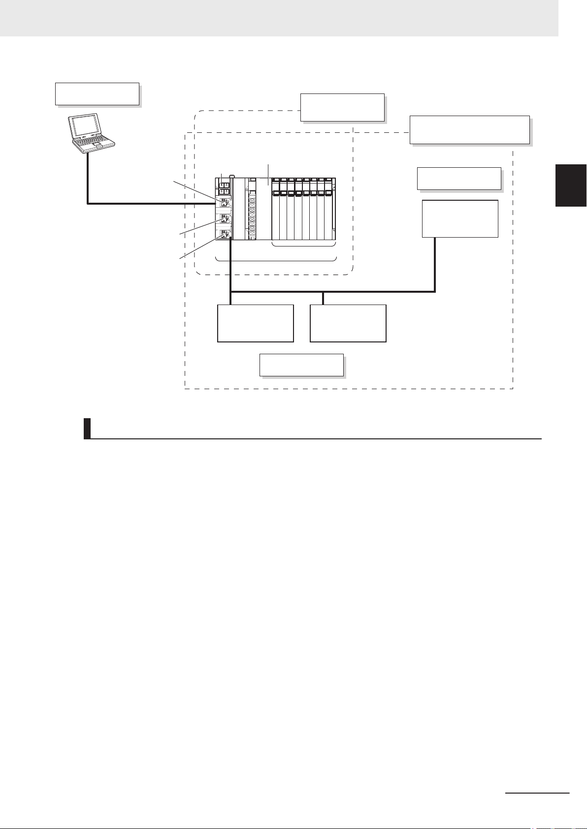
EtherNet/IP
Safety I/O terminal
Standard Controller
LAN
Support Software
CPU Rack
NX Units
EtherNet/IP
Built-in EtherNet/IP port 1
Built-in EtherNet/IP port 2A
Built-in EtherNet/IP port 2B
EtherNet/IP Field Network
Configuration
CPU Rack
Configuration
Communication
Control Unit
NX-CSG£££
Safety CPU Unit
NX-SL5£££
1 Overview
1-1 Overview of the Safety Net-
work Controller
1
1-1-2 Introduction to the System Configurations
Network Configuration between Controllers
The Safety Network Controller can perform CIP Safety on EtherNet/IP communications with other
Safety Network Controllers on the same network when the built-in EtherNet/IP port on the Communication Control Unit is connected to the EtherNet/IP network.
NX-series Safety Control Unit/Communication Control Unit User's Manual (Z395)
1-5
Page 60

EtherNet/IP
Communication
Control Unit
NX-CSG£££
Safety CPU Unit
NX-SL5£££
EtherNet/IP
Safety I/O terminal Safety I/O terminal
Standard Controller
Sysmac
Studio
EtherNet/IP
Communication
Control Unit
NX-CSG£££
Safety CPU Unit
NX-SL5£££
1 Overview
1-6
NX-series Safety Control Unit/Communication Control Unit User's Manual (Z395)
Page 61

Step 1-1 Determining Safety Measures by Performing Risk Assessment
Step 1-2 Selecting Safety Devices
Step 2-1 Designing I/O Devices and Processing
Step 2-1 Determining Wiring for Communications,
Power Supply, and External I/O Devices
Step 2-2 Designing Safety Programs
Step 3-2 Calculating Safety Reaction Times
Step 3-1 Calculating and Verifying Safety Communication Performance
Step 4-1 Creating the Safety Network Controller Configuration
Step 6-1 Transferring Data to the Controller
Step 4-3 Configuring the Communications Settings with Standard Controllers
Step 4-4 Assigning Safety I/O Terminals to the Connected Devices
Step 4-5 Assigning Device Variables to I/O Ports
Step 4-6 Exposing Variables to Standard Controllers
Step 4-2 Configuring the CIP Safety Communications Settings
Step 4-7 Programming
Step 4-8 Offline Debugging
Step 6-2 Checking Operation Using the Controller
Step 6-5 Setting the Safety Password
Step 6-3 Performing Safety Validation Testing
Step 6-4 Validating Safety from the Sysmac Studio
Step 3-3 Calculating Safety Distance and Verifying Fulfillment of Required Specifications
Step 7-1 Operation
Step 7-2 Troubleshooting Errors If They Occur
Step 7-3 Inspection and Replacement
Step 1-3 Selecting Network Devices
Step 1-4 Designing the Interface between Standard Controls and Safety Controls
Step 1-5 Designing the Interface between Safety Controls
Step 1-6 Designing Device Security
Step 1. System Design
Step 2. Software Design Step 2. Hardware Design
Step 3 Calculating and Verifying Safety Response Performance
Step 4. Software Settings and Programming
Step 6. Checking Operation
Step 7. Operation, Maintenance, and Inspection
Step 5-1 Installation
Step 5-2 Wiring the Unit Power Supply and the I/O
Step 5-3 Wiring the Ethernet Cables
Step 5-4 Connecting the Computer That Runs the Support Software
Step 5. Installation and Wiring
1 Overview
1-2
1-2-1
Procedure
Overall Procedure
Use the following procedure to build a safety control system.
1-2 Procedure
1
1-2-1 Overall Procedure
NX-series Safety Control Unit/Communication Control Unit User's Manual (Z395)
1-7
Page 62
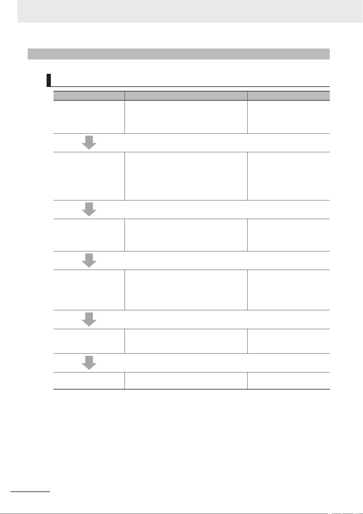
1 Overview
1-2-2
Detailed Procedures
Step 1. System Design
Procedure Description Reference
Step 1-1 Determining
Safety Measures by Performing Risk Assessment
Step 1-2 Selecting Safety
Devices
Step 1-3 Selecting Network Devices
• Identify potential danger factors and perform
risk assessment.
• Study and decide on measures to reduce
risks.
Select the safety devices for inputs, logic, and
outputs of the safety controls.
In consideration of the network bandwidth, select an Ethernet switch, a twisted-pair cable,
and a connector to configure the Ethernet network.
---
Section 2 System Configuration and Configuration Devices
on page
Section 3 Specifications of
Configuration Units on page
3-1
Selecting the Network Devices
on page
2-1
5-39
Step 1-4 Designing the Interface between Standard
Controls and Safety Controls
Step 1-5 Designing the Interface between Safety
Controls
Step 1-6 Designing Device
Security
Design the interface between the standard controls and safety controls.
Design the interface between safety controls. 7-4-2 CIP Safety Connection
Determine a safety password. 9-9-1 Setting the Safety Pass-
7-7 Exposing Variables to
Standard Controllers on page
7-40
6-1-4 Introduction to T
Links on page 6-4
Settings on page
word on page
9-48
ag Data
7-17
1-8
NX-series Safety Control Unit/Communication Control Unit User's Manual (Z395)
Page 63
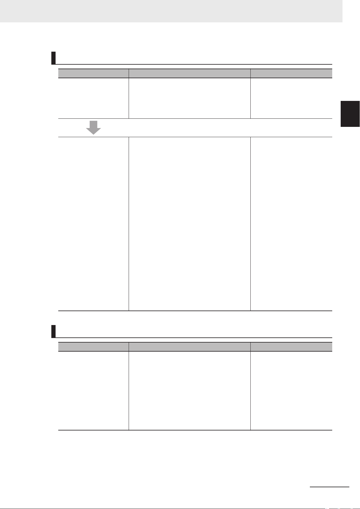
1 Overview
Step 2. Software Design
Procedure Description Reference
Step 2-1 Designing I/O Device and Processing
Step 2-2 Designing Safety
Programs
Design the configuration of the I/O devices and
I/O Units.
• Safety I/O devices
• Standard I/O devices
• Program contents
Design the POUs (Program Organization Units).
• Programs
• Function blocks
Design of Variables:
• Design the data types of the variables (partic-
ularly the design of safety data types and
standard data types).
• Define the variables that you will use in more
than one POU and variables that you will use
in only specific POUs.
• Define the variable names for the device vari-
ables that you use to access Safety I/O Units.
• Define the attributes of variables, such as the
Name attribute.
• Design the variables to expose to the user
program for the standard controls.
• Design the variables to expose to other user
program for the safety controls.
6-3 Safety I/O Function on
page 6-15
Section 8 Programming
page 8-1
9-9-2 Data Protection on page
9-49
on
1-2 Procedure
1
1-2-2 Detailed Procedures
Design of Data Protection:
• Design POUs to protect and access restric-
tions.
Step 2. Hardware Design
Procedure Description Reference
Step 2-1 Determining Wiring for Communications,
Power Supply
nal I/O Devices
, and Exter-
Determine the wiring for the communications
network, power supply, and safety I/O devices.
Section 3 Specifications of
Configuration Units on page
3-1
Section 4 Designing the Power Supply System on page
4-1
6-3 Safety I/O Function on
page 6-15
Section 5 Installation and Wiring on page 5-1
NX-series Safety Control Unit/Communication Control Unit User's Manual (Z395)
1-9
Page 64

1 Overview
Step 3. Calculating and Verifying Safety Response Performance
Step 3-1 Calculating Safety Communications Performance
Procedure Description Reference
Calculate safety task period, EPI and FSoE
, and verify the bandwidth usage.
WDT
Section 10 Calculating Safety
Reaction Times on page 10-1
Section 11 Communications
Load on page 11-1
Step 3-2 Calculating Safety Reaction T
Step 3-3 Calculating Safety Distance and V
Fulfillment of Required
Specifications
imes
erifying
Calculate the safety reaction time. Section 10 Calculating Safety
Calculate the safety distances from the safety
reaction times. Check to see if the safety distances meet the requirements. If requirements are
not met, reconsider the designs again starting
with the system design.
Step 4. Software Settings and Programming
Procedure Description Reference
Step 4-1 Creating the
Safety Network Controller
Configuration
Step 4-2 Configuring the
CIP Safety Communications Settings
On the Sysmac Studio, configure the Communication Control Unit
I/O Units, and the other NX Units.
Configure the CIP Safety communications settings.
, Safety CPU Units, Safety
Reaction Times on page 10-1
---
7-3 CPU Rack Configuration
and Setup on page 7-5
7-4 EtherNet/IP Network Configuration and Setup on page
7-9
1-10
Step 4-3 Configuring the
Communications Settings
with Standard Controllers
Step 4-4 Assigning Safety
I/O Terminals to the Connected Devices
Step 4-5 Assigning Device
V
ariables to I/O Ports
Step 4-6 Exposing Variables to Standard Controllers
Configure the communication settings with
standard controllers.
On the parameter setting page for the Safety I/O
Units, select the safety I/O devices that are connected to the safety I/O terminals.
Register the device variables in the global variable table.
Specify variables to be exposed to the standard
controllers.
NX-series Safety Control Unit/Communication Control Unit User's Manual (Z395)
7-4 EtherNet/IP Network Configuration and Setup on page
7-9
7-5 Setting the Input and Output Functions on page 7-29
7-6 Assigning Variables to I/O
Ports on page 7-33
7-7 Exposing Variables to
Standard Controllers on page
7-40
Page 65
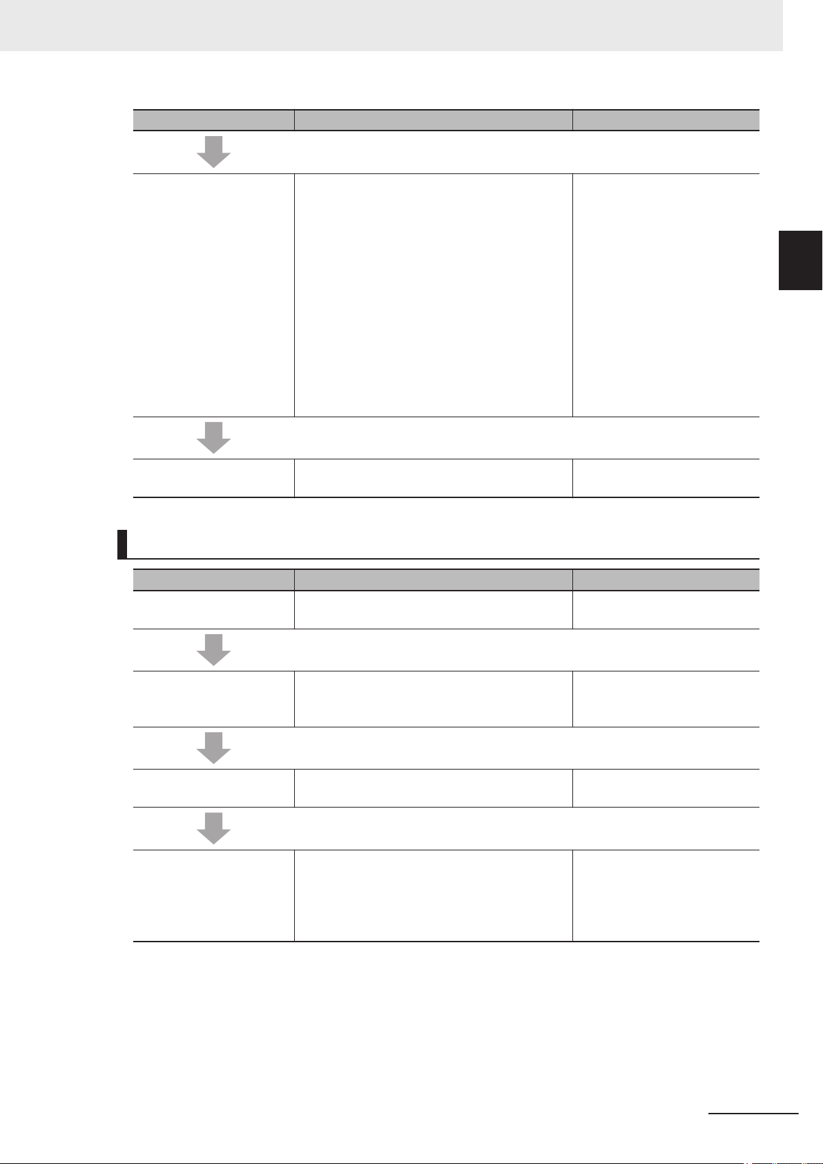
1 Overview
Procedure Description Reference
1-2 Procedure
Step 4-7 Programming Variable Registration:
• Register the variables that are used by more
than one POU in the global variable table with
the Sysmac Studio.
8-5 Programming Operations
on page 8-27
• Register the variables that are used in only a
specific program in the local variable table for
that program.
• Register the variables that are used in only a
specific function block in the local variable table for that function block.
riting Algorithms for POUs:
W
Write the algorithms for the POUs (programs
and function blocks) using the FBD language.
Step 4-8 Offline Debugging The Simulator is used to debug the program. 8-9 Offline Debugging
8-96
Step 5. Installation and Wiring
Procedure Description Reference
Step 5-1 Installation Mount the Units on a DIN Track and connect the
Units to each other.
Section 5 Installation and Wiring on page 5-1
1
1-2-2 Detailed Procedures
on page
Step 5-2 Wiring the Unit
Power Supply and the I/O
Step 5-3 Wiring the Ethernet Cables
Step 5-4 Connecting the
Computer That Runs the
Support Software
Wire cables and connectors of the Communication Control Unit
other NX Units.
Connect the Communication Control Unit to the
Ethernet network.
Connect the computer to the built-in EtherNet/IP
port on the Communication Control Unit
Ethernet cable.
, the Safety I/O Units, and the
with an
Section 5 Installation and Wiring on page 5-1
Section 5 Installation and Wiring on page
2-2 Connecting the Support
Software on page 2-5
Sysmac Studio Version 1
Operation Manual (Cat. No.
W504)
5-1
NX-series Safety Control Unit/Communication Control Unit User's Manual (Z395)
1-11
Page 66

1 Overview
Step 6. Checking Operation
Step 6-1 Transferring Data
to the Controller
Procedure Description Reference
Place the Sysmac Studio online with the Communication Control Unit
uration information from a computer to the Controller.
Then, change the Safety CPU Unit to DEBUG
mode from the Safety CPU Unit Setup and Programming View.
This transfers the safety application data to the
Safety CPU Unit and enables debugging.
and transfer the config-
9-2 Transferring the Configuration Information on page 9-6
9-3 Operating Modes of the
Safety CPU Unit on page 9-8
9-4 Changing to DEBUG Mode
on page 9-13
Step 6-2 Checking Operation Using the Controller
Step 6-3 Performing Safety
alidation Testing
V
Step 6-4 Validating Safety
from Sysmac Studio
Step 6-5 Setting the Safety
Password
Check all wiring and the operation of the program to check that the Safety Control Unit operates as intended.
Test all safety functions to see if they operate
according to designs.
After the safety validation testing has been
passed, execute the Safety V
from the Sysmac Studio.
This transfers the safety application data to the
non-volatile memory in the Safety CPU Unit and
enables operation.
Set the safety passwords. 9-9 Security Settings
alidation operation
9-6 Functions for Checking Operation
9-6 Functions for Checking Operation on page 9-22
9-10 Performing Safety Validation and Operation on page
9-53
9-48
on page 9-22
on page
1-12
NX-series Safety Control Unit/Communication Control Unit User's Manual (Z395)
Page 67

1 Overview
Step 7. Operation, Maintenance, and Inspection
Procedure Description Reference
Step 7-1 Operation Restart the Safety CPU Unit.
Safety CPU Unit has a validated user pro-
If the
gram, the Safety CPU Unit will automatically
start in RUN mode.
Step 7-2 Troubleshooting
Errors If They Occur
Step 7-3 Inspection and
Replacement
If an error occurs, use the troubleshooting function of the Sysmac Studio to check the error and
determine the cause. Then, remove the error
Perform periodic maintenance.
If you find any defects or problems during the inspection, replace the af
fected devices.
.
9-10 Performing Safety Validation and Operation on page
9-53
Section 15 Troubleshooting on
page 15-1
Section 16 Inspection and
Maintenance on page 16-1
1-2 Procedure
1
1-2-2 Detailed Procedures
NX-series Safety Control Unit/Communication Control Unit User's Manual (Z395)
1-13
Page 68

1 Overview
1-14
NX-series Safety Control Unit/Communication Control Unit User's Manual (Z395)
Page 69

2
System Configuration and Configuration Devices
This section describes how to configure the Safety Network Controller system, and
provides information on configuration devices in the system.
2-1
Basic Configuration .......................................................................................2-2
2-1-1 CPU Rack Configuration ................................................................................. 2-2
2-1-2 EtherNet/IP Field Network Configuration ........................................................ 2-3
2-1-3 Configuration Units.......................................................................................... 2-3
2-2 Connecting the Support Software ................................................................ 2-5
2-3 Network Configuration between Controllers............................................... 2-6
2
NX-series Safety Control Unit/Communication Control Unit User's Manual (Z395)
2-1
Page 70

Communication
Control Unit
NX-CSG£££
SD Memory
Card
Safety CPU Unit
NX-SL5£££
End Cover
NX Units
(up to 32 units)
2 System Configuration and Configuration Devices
2-1
2-1-1
Basic Configuration
The configuration that includes the Safety CPU Unit, the Communication Control Unit, as well as the
Units of which input and output are directly controlled by the Safety CPU Unit and the Communication
Control Unit, is called the Basic Configuration.
Basic Configuration is as follows. These configurations can exist together.
• CPU Rack Configuration
• EtherNet/IP Field Network Configuration
CPU Rack Configuration
The following shows the CPU Rack Configuration, where NX Units are mounted to a CPU Rack. The
CPU Rack is configured with a Communication Control Unit, Safety CPU Unit, Safety I/O Units, other
NX Units, and an End Cover mounted to it.
The number of NX Unit connections is up to 32 units.
2-2
Configuration Remarks
Communication Control Unit
NX-CSG£££
End Cover Must be connected to the right side of the CPU Rack. One end cov-
NX Unit Safety CPU Unit
SD Memory Card Install as required.
NX-SL5£££
Safety Input Unit
Safety Output Unit
Other NX Units
One required for every CPU Rack.
er is provided with the Communication Control Unit as a standard
accessory
Up to 32 units can be mounted onto the CPU Rack. One Safety
CPU Unit is required for each CPU Rack.
Refer to A-18 V
that you can connect.
NX-series Safety Control Unit/Communication Control Unit User's Manual (Z395)
.
ersion Information on page A-109 for the NX Units
Page 71

EtherNet/IP
End Cover
Communication
Control Unit
NX-CSG£££
Safety CPU Unit
NX-SL5£££
SD Memory
Card
Built-in EtherNet/IP
port 2B
Built-in EtherNet/IP
port 2A
Built-in EtherNet/IP
port 1
CIP Safety on
EtherNet/IP Device
St
andard
Controller
2 System Configuration and Configuration Devices
2-1-2
EtherNet/IP Field Network Configuration
The EtherNet/IP field network configuration consists of Communication Control Unit, Safety CPU Unit,
an End Cover
The Safety Network Controller performs communications with devices that support CIP Safety on
EtherNet/IP and standard controllers by connecting the built-in EtherNet/IP port of the Communication
Control Unit to the EtherNet/IP network.
, a device that supports CIP Safety on EtherNet/IP, and a standard controller.
2-1 Basic Configuration
2
2-1-2 EtherNet/IP Field Network Configuration
2-1-3
Configuration Remarks
Communication Control Unit
NX-CSG£££
End Cover Must be connected to the right side of the CPU Rack. One End
NX Unit Safety CPU Unit
SD Memory Card Install as required.
CIP Safety on EtherNet/IP Device These are connected to the EtherNet/IP network to which the builtStandard Controller
NX-SL5£££
One required for every CPU Rack.
Cover is provided with the
ard accessory.
One Safety CPU Unit required for every CPU Rack.
in EtherNet/IP port of the Communication Control Unit
Communication Control Unit as a stand-
is connected.
Configuration Units
Communication Control Unit
l
The Communication Control Unit has built-in EtherNet/IP ports and relays CIP Safety communications between the Safety CPU Unit and CIP Safety on EtherNet/IP devices. It also supports tag data link communications with standard controllers.
Refer to 3-1
Communication Control Unit.
Communication Control Unit on page 3-2 for the models and specifications of the
NX-series Safety Control Unit/Communication Control Unit User's Manual (Z395)
2-3
Page 72

2 System Configuration and Configuration Devices
SD Memory Card
l
When you insert an SD Memory Card into the Communication Control Unit, various data can be
saved, backed up, restored and compared using the SD Memory Card.
Refer to 3-6 SD Memory Cards on page
Memory Card.
Safety CPU Unit
l
This Unit serves as the center of control for the Safety Network Controllers. It is an NX Unit that
executes safety programs and safety process data communications.
Refer to 3-2 Safety CPU Unit on page 3-22 for the models and specifications of Safety CPU Units.
Safety Input Unit
l
This is an NX Unit that performs safety input processing.
Refer to 3-3 Safety Input Unit on page 3-32 for the models and specifications of Safety Input Unit.
Safety Output Unit
l
This an NX Unit that performs safety output processing.
Refer to 3-4 Safety Output Unit on page 3-45 for the models and specifications of Safety Output
Unit.
3-60 for the models and specifications of individual SD
End Cover
l
A cover to protect the Communication Control Unit and NX Unit. This is provided with the Communication Control Unit.
Refer to 3-5 End Cover on page 3-59 for the models and specifications of the end cover.
Other NX Units
l
This is an NX Unit that performs standard I/O processing.
Refer to A-18 Version Information on page A-109 for the NX Units that you can connect.
Refer to the user's manuals of the each NX Unit for the models and specifications.
CIP Safety on EtherNet/IP Device
l
The Safety CPU Unit performs safety controls on devices that are compliant with CIP Safety on
EtherNet/IP, such as safety I/O terminals.
Standard Controller
l
This controller performs I/O communications and message communications with the Safety CPU
Unit via the built-in EtherNet/IP port of the Communication Control Unit.
2-4
NX-series Safety Control Unit/Communication Control Unit User's Manual (Z395)
Page 73

2 System Configuration and Configuration Devices
2-2 Connecting the Support Software
2-2
Connecting the Support Software
The Safety Network Controller and the Support Software can be connected each other via the built-in
EtherNet/IP port of the Communication Control Unit. Refer to 3-7-2 Connection on page 3-62 for information on the connection between Safety Network Controller and the Support Software.
2
NX-series Safety Control Unit/Communication Control Unit User's Manual (Z395)
2-5
Page 74
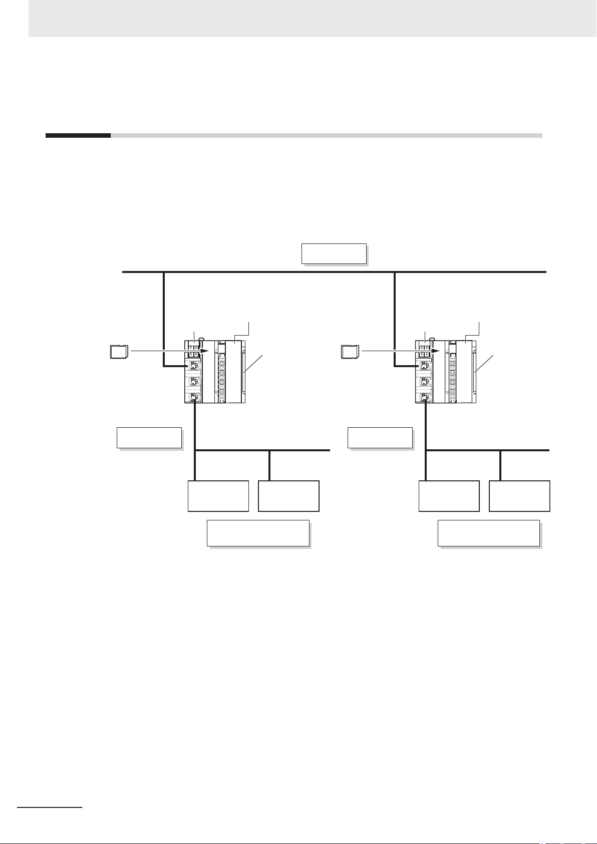
EtherNet/IP
EtherNet/IP
End Cover
EtherNet/IP
Safety CPU Unit
NX-SL5£££
End Cover
Communication
Control Unit
NX-CSG£££
Safety CPU Unit
NX-SL5£££
SD Memory
Card
SD Memory
Card
Communication
Control Unit
NX-CSG£££
CIP Safety on
EtherNet/IP Device
CIP Safety on
EtherNet/IP Device
2 System Configuration and Configuration Devices
2-3
Network Configuration between Controllers
The network configuration between Controllers consists of multiple Safety Network Controllers. You
can configure network between Controllers when you connect the built-in EtherNet/IP ports of Communication Control Unit to the EtherNet/IP network. This network provides CIP Safety on EtherNet/IP
communications between multiple network controllers.
For details on configuration devices, refer to 2-1-3 Configuration Units on page 2-3.
2-6
NX-series Safety Control Unit/Communication Control Unit User's Manual (Z395)
Page 75

3
Specifications of Configuration
Units
3
This section provides the specifications of the configuration units.
3-1
Communication Control Unit ........................................................................3-2
3-1-1 Models and Specifications............................................................................... 3-2
3-1-2 Built-in EtherNet/IP Port Specifications ........................................................... 3-7
3-1-3 Part Names and Functions............................................................................ 3-10
3-1-4 Terminal Blocks ............................................................................................. 3-12
3-1-5 Indicators....................................................................................................... 3-14
3-1-6 ID Information Indication ............................................................................... 3-21
3-2 Safety CPU Unit............................................................................................ 3-22
3-2-1 Models and Specifications............................................................................. 3-22
3-2-2 Part Names and Functions............................................................................ 3-26
3-2-3 Indicators....................................................................................................... 3-27
3-3 Safety Input Unit........................................................................................... 3-32
3-3-1 Models and Specifications............................................................................. 3-32
3-3-2 Part Names and Functions............................................................................ 3-38
3-3-3 Indicators....................................................................................................... 3-40
3-4 Safety Output Unit........................................................................................ 3-45
3-4-1 Models and Specifications............................................................................. 3-45
3-4-2 Part Names and Functions............................................................................ 3-52
3-4-3 Indicators....................................................................................................... 3-55
3-5 End Cover .....................................................................................................3-59
3-5-1 Models and Specifications............................................................................. 3-59
3-6 SD Memory Cards ........................................................................................3-60
3-6-1 Models and Specifications............................................................................. 3-60
3-6-2 Purpose ......................................................................................................... 3-60
3-7 Support Software .........................................................................................3-61
3-7-1 Product Model ............................................................................................... 3-61
3-7-2 Connection .................................................................................................... 3-62
3-8 PFH ................................................................................................................3-63
NX-series Safety Control Unit/Communication Control Unit User's Manual (Z395)
3-1
Page 76

3 Specifications of Configuration Units
3-1
3-1-1
Communication Control Unit
This section describes the models and specifications of the Communication Control Unit as well as the
names and functions of the parts.
Models and Specifications
This section describes the specifications of the Communication Control Unit.
Models and Outline of Specifications
The models and outline of specifications of the Communication Control Unit are given below.
Model Supported communications protocol Number of communications connectors Network variables
NX-CSG320
*1. Routing of the CIP Safety protocol is supported.
*2. PORT1 is an independent port. PORT2A and PORT2B are the ports with a built-in Ethernet switch.
EtherNet/IP
*1
3
*2
2
3-2
NX-series Safety Control Unit/Communication Control Unit User's Manual (Z395)
Page 77

General Specifications
3 Specifications of Configuration Units
This section provides the general specifications of the Communication Control Unit.
Item Specification
Enclosure Mounted in a panel (open type)
Grounding method Ground to 100 Ω or less
Operating environment Ambient operating tem-
perature
Ambient operating humidity
Atmosphere Must be free from corrosive gases
Ambient storage temperature
Altitude 2,000 m max.
Pollution degree 2 or less: Meets IEC 61010-2-201
Noise immunity Conforms to IEC 61131-2, 2 kV (power supply line)
Insulation class CLASS III (SELV)
Overvoltage category Category II: Meets IEC 61010-2-201
EMC immunity level Zone B
Vibration resistance Conforms to IEC 60068-2-6
Shock resistance Conforms to IEC 60068-2-27
Insulation resistance 20 MΩ between isolated circuits (at 100 VDC)
Dielectric strength 510 VAC between isolated circuits for 1 minute at a
Installation method DIN Track mounting (IEC 60715 TH35-7.5/TH35-15)
0 to 55°C
10% to 95% (with no condensation or icing)
−25 to 70°C (with no condensation or icing)
5 to 8.4 Hz with amplitude of 3.5 mm
8.4 to 150 Hz, acceleration of 9.8 m/s
100 min. in each X, Y
10 min. each = 100 min. total)
147 m/s
3 times in each X, Y
leakage current of 5 mA max.
2
, and Z directions (10 sweeps of
, and Z directions
2
3-1 Communication Control Unit
3
3-1-1 Models and Specifications
NX-series Safety Control Unit/Communication Control Unit User's Manual (Z395)
3-3
Page 78
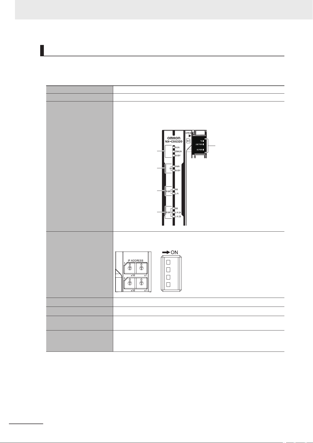
[SD PWR] indicator,
[SD BUSY] indicator
[TS] indicator,
[UNIT PWR] indicator,
[I/O PWR] indicator
[NS] indicator,
[
L/A] indicator
[NS] indicator,
[
L/A 2A] indicator,
[L/A 2B] indicator
[RUN] indicator,
[ERROR] indicator,
[BUSY] indicator
3 Specifications of Configuration Units
Individual Specifications
This section provides the individual specifications of Communication Control Unit.
NX-CSG320
l
Unit name Communication Control Unit
Model NX-CSG320
Indicators [RUN] indicator, [ERROR] indicator, [BUSY] indicator, [SD PWR] indicator, [SD
BUSY] indicator
indicator, [TS] indicator, [UNIT PWR] indicator, [I/O PWR] indicator
, [NS] indicator x 2, [L/A] indicator, [L/A 2A] indicator, [L/A 2B]
Hardware switch settings [IP ADDRESS 1] Switch (x16, x1), [IP ADDRESS 2] Switch (x16, x1), DIP
Switch
Dimensions
Weight
*1
*2
Number of NX Units that
72 × 100 × 90 mm (W × H × D)
390 g
32 units or less
you can connect
Number of communications
254 ports max.
*6
that can be set between NX
Units
3-4
NX-series Safety Control Unit/Communication Control Unit User's Manual (Z395)
Page 79
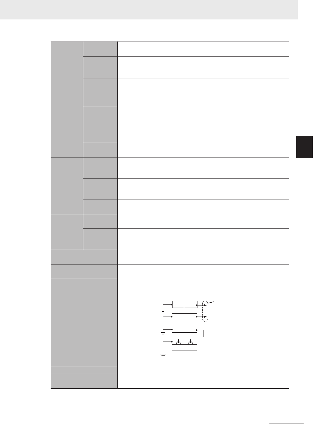
IOV
U
G
UV
IOG
UV
UG
A1
A8
B1
B8
NX Unit power supply
(24 VDC)
I/O power supply
(5 to 24 VDC)
Ground of 100 Ω
or less
Through-wiring for
unwired terminals
3 Specifications of Configuration Units
Unit power
supply
Power supply voltage
Unit power
consump-
*3
tion
Inrush cur-
*4
rent
Current capacity of
power supply termi-
*5
nal
Isolation
method
Power supply to the
NX Unit
power supply
NX Unit power supply capacity
NX Unit power supply efficiency
Isolation
method
I/O power
supply to
NX Units
Power supply voltage
Maximum I/O
power supply current
Current consumption from
I/O power supply
External connection terminals
Terminal connection diagram
24 VDC (20.4 to 28.8 VDC)
5.95 W
For cold start at room temperature:
10 A max./0.1 ms max.
and
2.5 A max./150 ms max.
4 A
No isolation: Between the Unit power supply terminal and internal circuit
10 W max.
80%
No isolation: Between the Unit power supply terminal and NX Unit power supply
5 to 24 VDC (4.5 to 28.8 VDC)
4 A
10 mA max. (24 VDC)
Screwless clamping terminal block (8 terminals)
UV/UG: Unit power supply terminals
IOV/IOG: I/O power supply terminals
3-1 Communication Control Unit
3
3-1-1 Models and Specifications
NX-series Safety Control Unit/Communication Control Unit User's Manual (Z395)
Accessories End cover (NX-END02): 1 pc.
Installation orientation and
restrictions
Only upright installation orientation
*1. Includes the End Cover, and does not include projecting parts.
*2. Includes the End Cover. The weight of the End Cover is 82 g.
*3. Includes the SD Memory Card. The NX Unit power consumption to NX Units is not included.
*4. This is the inrush current value when the power supply turns ON after it has been OFF.
3-5
Page 80

3 Specifications of Configuration Units
The inrush current may vary depending on the operating condition and other conditions. Therefore, select
fuses, breakers, and external power supply devices that have enough margin in characteristic and capacity
considering the condition under which the devices are used.
Especially when you turn the power ON/OFF through a switch inserted to the external DC power supply, cycling power ON-OFF-ON within one second will cause the inrush current of approx. 30 A/0.3 mA to occur
since the inrush current limiter circuit fails to limit the current.
*5. The amount of current that can be passed constantly through the terminal. Do no exceed this current value
when you use a through-wiring for the Unit power supply.
*6. The actual configurable number can be calculated as follows: 254 - <Number of CIP Safety connections
configured> - <Number of FSoE connections configured>
,
3-6
NX-series Safety Control Unit/Communication Control Unit User's Manual (Z395)
Page 81

3 Specifications of Configuration Units
3-1-2
Built-in EtherNet/IP Port Specifications
The following table shows the specifications of the built-in EtherNet/IP port of the Communication Control Unit.
Item
Communications protocol TCP/IP or UDP/IP
Sysmac Studio connection, tag data links, CIP message communications,
Supported services
Number of logical ports 2 (With IP routing function)
Physical layer
Media access
method
Modulation Baseband
Transmission
paths
Transmission
specifications
CIP Safety routing
Baud rate 100 Mbps (100BASE-TX)
Transmission media
Transmission distance
Number of cascade connections
Maximum number
of routable CIP
Safety connections
Maximum routable
safety data length
per connection
FTP server
(client), BOOTP (client), TCP/UDP message service
100Base-TX or 10Base-T (100Base-TX is recommended.)
CSMA/CD
Star form
Shielded twisted-pair (STP) cable, Category 5, 5e or higher
100 m max. (distance between hub and node)
The built-in switching ports support up to 50 nodes.
There is no limitation when an external Ethernet switch is used.
254 total
For multi-cast connections, 128 total
32 bytes
, automatic clock adjustment (NTP client), SNMP (agent), DNS
3-1 Communication Control Unit
Specification
NX-CSG£££
*1
3
3-1-2 Built-in EtherNet/IP Port Specifications
NX-series Safety Control Unit/Communication Control Unit User's Manual (Z395)
3-7
Page 82

3 Specifications of Configuration Units
Item
Number of connections
32/Logical ports
(total of 64 with two logical ports)
Specification
NX-CSG£££
1 to 10,000 ms in 1-ms increments
Packet interval
(refresh cycle)
Packet intervals can be set independently for each connection. (Data is refreshed over the network at preset intervals and does not depend on the
number of nodes.)
Allowed communications bandwidth
12000 pps
Note: The heartbeat and CIP Safety routing are included.
*2
per Unit
Number of registrable tags
1024/Logical ports
(total of 2048 with two logical ports)
Tag types Network variables
CIP service:
ag data links
T
(cyclic communications)
Number of tags
per connection (=
1 tag set)
Maximum link data
size per node
Maximum data
size per connec-
32 (31 tags if Controller status is included in the tag set.)
46,208 bytes/Logical ports
92,416 bytes total
1,444 bytes
*3
Data concurrency is maintained within each connection.
tion
32 per port
(1 connection = 1 tag set)
(total of 40*4 with two logical ports)
1,444 bytes
wo bytes are used if Controller status is included in the tag set.)
(T
Supported.
Connections: 16/Logical ports
(total of 32 with two logical ports)
(server only)
Maximum number of clients that can communicate at one time: 16 per port
(total of 32 with two logical ports)
Maximum number of servers that can communicate at one time: 16 per port
CIP message service:
Explicit
messages
*6
Number of registrable tag sets
Maximum size of 1
tag set
Multi-cast packet
*5
filter
Class 3 (number of
connections)
UCMM (unconnected)
(total of 32 with two logical ports)
Maximum number
16 per port (total of 32 with two logical ports)
of clients that can
TCP/UDP message
service
SNMP
communicate at
one time
Maximum message size
Request: 492 bytes
Response: 496 bytes
Agent SNMPv1, SNMPv2c
MIB MIB-II
EtherNet/IP conformance test Conforms to CT14
Ethernet interface
10BASE-T or 100BASE-TX
Auto negotiation or fixed settings
*1. If tag data links are being used, use 100Base-TX.
*2. Here, pps means “packets per second” and indicates the number of packets that can be processed in one second.
*3. To use a data size of 505 bytes or higher, the system must support a large forward open (an optional CIP specifica-
tion). The CS, CJ, NJ, and NX-series Units support a large forward open, but before connecting to nodes of other companies, confirm that those devices also support it.
3-8
NX-series Safety Control Unit/Communication Control Unit User's Manual (Z395)
Page 83

3 Specifications of Configuration Units
*4. If more than 40 tag sets are registered in total, the T
event will occur.
*5. Because the built-in EtherNet/IP port is equipped with an IGMP client (version 2), unnecessary multicast packets can
be filtered out by an Ethernet switch that supports IGMP Snooping.
*6. The built-in EtherNet/IP port uses the TCP/UDP port numbers shown in the following table.
Do not set the same port number for more than one TCP/UDP service.
Service Type Port number Remarks
Tag data links UDP 2222 Fixed values
Used by system UDP 2223, 2224
TCP 9610
CIP messages TCP 44818
FTP client
(Data transfer port)
DNS client TCP/UDP 53
BOOTP client UDP 68
HTTP server TCP 80
Used by system, other TCP/UDP 9600 You can change the port number in the
FTP client
(Control port)
TCP/UDP message service TCP/UDP 64000
NTP client UDP 123
SNMP agent UDP 161
SNMP trap UDP 162
TCP 20
TCP 21
ag Data Link, Too Many Tag Sets Registered (840E0000 hex)
Unit Settings on the Sysmac Studio.
3-1 Communication Control Unit
3
3-1-2 Built-in EtherNet/IP Port Specifications
NX-series Safety Control Unit/Communication Control Unit User's Manual (Z395)
3-9
Page 84

(A) (B)
(E)
(C)
(D)
(G)
(M)
(H) (J)(I)
(N)(P) (O) (L)
(K)
(F)
3 Specifications of Configuration Units
3-1-3
Part Names and Functions
This section provides the part names and functions of Communication Control Unit.
Letter Name Function
(A) SD Memory Card con-
(B) SD Memory Card pow-
(C) DIN Track mounting
(D) Terminal Block Used for wiring the power supply and functional grounding wire.
(E) NX bus connector This connector is used to connect the Communication Control Unit to the NX
nector
er supply switch
hooks
Connects the SD Memory Card to the Communication Control Unit.
Turns OFF the power supply so that you can remove the SD Memory Card.
Refer to 5-2-8 Installing and Removing the SD Memory Card
These hooks are used to mount the Unit to a DIN Track.
Unit on the right of the Communication Control Unit.
on page 5-21.
3-10
NX-series Safety Control Unit/Communication Control Unit User's Manual (Z395)
Page 85

3 Specifications of Configuration Units
Letter Name Function
(F) IP Address Switch 2
(x16, x1)
(G) IP Address Switch 1
(x16, x1)
(H) SD Memory Card cover A cover for the SD Memory Card DIP switch area. It opens in the horizontal
(I) Operation Status Indi-
cators
(J) End Cover A cover to protect the Communication Control Unit and NX Unit. One End
(K) DIN Track contact plate This plate is used to contact the functional ground terminal with a DIN Track.
(L) Unit hookup guides These guides are used to mount NX Units or End Cover.
(M) ID Information Indica-
tion
(N) DIP Switch Used for backups. Normally, turn OFF all of the pins.
(O) Built-in EtherNet/IP Port
T2)
(POR
(P) Built-in EtherNet/IP Port
T1)
(POR
Used for setting an IP address for the built-in EtherNet/IP port (PORT2A and
T2B). Use the rotary switches and specify a two-digit hexadecimal num-
POR
ber.
Refer to 7-4-1 Setting IP Addresses on page 7-9.
Used for setting an IP address for the built-in EtherNet/IP port (PORT1). Use
the rotary switches and specify a two-digit hexadecimal number
Refer to 7-4-1 Setting IP Addresses on page 7-9.
direction.
Show the operation status of Communication Control Unit by multiple indica-
tors.
Cover is provided with the
sory.
Shows the ID information of the Unit.
Refer to 13-2 SD Memory Card Backups on page
Connects the built-in EtherNet/IP with an Ethernet cable.
PORT2 consists of two RJ45 connectors (PORT2A and PORT2B) and has a
built-in Ethernet switch.
Connects the built-in EtherNet/IP with an Ethernet cable.
Communication Control Unit as a standard acces-
13-10.
.
3-1 Communication Control Unit
3
3-1-3 Part Names and Functions
NX-series Safety Control Unit/Communication Control Unit User's Manual (Z395)
3-11
Page 86

8-terminal type
(A)
A1
A2
A3
A4
A5
A6
A7
A8
B1
B2
B3
B4
B5
B6
B7
B8
(B)
(C)
NX-TBC082
(D)
3 Specifications of Configuration Units
3-1-4
Terminal Blocks
The terminal blocks on the Communication Control Unit are removable screwless clamping terminal
blocks that allow you to easily connect and remove the wiring.
Use the NX-TBC082 for the Communication Control Unit
.
Connect the Unit power supply, I/O power supply, and ground wire to the screwless clamping terminal
block.
For details on wiring, refer to 5-3 Wiring on page 5-32.
Terminal Block Part Names and Functions
3-12
Letter Name Function
(A) Terminal number in-
dications
(B) Release hole Insert a flat-blade screwdriver into these holes to connect or remove the wires.
(C) Terminal hole The wires are inserted into these holes.
(D) Ground terminal
mark
The terminal numbers are given by column letters A and B, and row numbers 1
to 8.
The combination of the
to A8 and B1 to B8.
The terminal number indicators are the same regardless of the number of terminals on the terminal block, as shown above.
This mark indicates the ground terminals.
"column" and "row" gives the terminal numbers from A1
Terminal Blocks come in three types depending on the number of terminals that can be used. There
are 8-terminal, 12-terminal, and 16-terminal T
erminal Blocks.
Only the 8-terminal type terminal block is compatible with Communication Control Unit.
To prevent incorrect insertion, terminal blocks in any other types besides the 8-terminal type cannot be
mounted.
Additional Information
The 8-terminal type does not have terminal holes and release holes for following terminal numbers.
•
A2, A4, A6, A8, B2, B4, B6, and B8
NX-series Safety Control Unit/Communication Control Unit User's Manual (Z395)
Page 87

3 Specifications of Configuration Units
Applicable Terminal Blocks for Each Model
Current capacity of power supply terminals and applicable terminal blocks for each model of Communication Control Unit
Unit model
number
NX-CSG320 4 A NX-TBC082 8 Provided 10 A
are shown in the following table.
Current capacity of power sup-
ply terminal for the Unit
Unit power
supply
I/O power sup-
ply
Terminal
block model
Terminal block
Number
of termi-
nals
Ground ter-
minal mark
Terminal
current
capacity
Precautions for Correct Use
Current capacity of power supply terminal for NX-CSG320 is 4 A or less. Make sure that each
current rating of the Unit power supply and I/O power supply does not change if you mount an
NX-TBC082 T
erminal Block that has terminal current capacity of 10 A.
3-1 Communication Control Unit
3
3-1-4 Terminal Blocks
NX-series Safety Control Unit/Communication Control Unit User's Manual (Z395)
3-13
Page 88

(A)
(E)
(F)
(B)
(C)
(D)
3 Specifications of Configuration Units
3-1-5
Indicators
This section describes the indicators of Communication Control Unit.
Note that the appearance of the indicators is dif
date on or before March 19, 2019, from that representing the date on or after March 20, 2019. This
manual shows the indicators for lot numbers representing the date on or after March 20, 2019.
For details on the differences in appearance of the indicators, refer to Differences in Appearance of
the Indicators on page 3-20.
Refer to Notation of Unit Versions on Products on page 43 for how to identify the lot number of the
Unit.
ferent for the Unit with the lot number representing the
Letter Name Function
(A) Model number display Displays the model information of Communication Control Unit.
(B) Communication Control Unit Sta-
tus Indicators
(C) Built-in EtherNet/IP Status Indica-
tors (POR
(D) Built-in EtherNet/IP Status Indica-
tors (POR
(E) NX Bus Status Indicators These indicators show the communications status with Communi-
(F) Power Status Indicators Show the power supply status of the Unit and I/O power supply.
T1)
T2)
The indicators show the current operating status of Communication Control Unit
The indicators show the communications status of Built-in EtherNet/IP Port (PORT1).
The indicators show the communications status of Built-in EtherNet/IP Port (PORT2).
cation Control Unit
.
and NX Units.
Communication Control Unit Status Indicators
These indicators show the major operating status of Communication Control Unit.
3-14
NX-series Safety Control Unit/Communication Control Unit User's Manual (Z395)
Page 89

3 Specifications of Configuration Units
Precautions for Safe Use
• Never turn OFF the power supply to the Communication Control Unit when the BUSY indicator is flashing. While the BUSY indicator is flashing, a backup of the setting values into the
built-in non-volatile memory is in progress. If you turn the power OFF during that time, the
backup will fail. In addition, the controller error in the major fault level occurs at the next startup, which causes the operation to stop.
•
Never turn the power OFF or remove the SD Memory Card while the card is in use (SD
BUSY indicator is flashing). This may cause data corruption, and the data may not work as
intended. To remove the SD Memory Card from the Communication Control Unit while the
power supply is ON, press the SD Memory Card power supply switch first. Make sure that the
SD BUSY Indicator and the SD PWR Indicator are turned OFF before you remove the SD
Memory Card.
The status indicators for the Communication Control Unit (RUN, ERROR, BUSY, SD PWR, and SD
BUSY indicators) allow you to check the operating status of
For details on how to check the operating status of the Communication Control Unit, refer to 15-1 Op-
eration after an Error on page 15-2.
Communication Control Unit.
3-1 Communication Control Unit
3
3-1-5 Indicators
The meaning of the indicators is shown below.
RUN Indicator
l
The RUN indicator shows the operating status of Communication Control Unit.
The following table lists the possible states for this indicator and what they mean.
Color Status Meaning
Green Lit The Unit is operating normally.
Flashing The Unit is starting up.
--- Not lit The CPU reset is in progress or any of the following errors is present.
• Major fault level Controller error
atchdog Timer Error
ERROR Indicator
l
• CPU Unit W
The ERROR indicator shows the error status of Communication Control Unit.
The following table lists the possible states for this indicator and what they mean.
Color Status Meaning
Red
Lit Any of the following errors was detected during self-diagnosis.
• Major fault level Controller error
• CPU error
Flashing (at 1-s intervals) Any of the following errors was detected during self-diagnosis.
• Partial fault level Controller error
• Minor fault level Controller error
--- Not lit Operating normally or resetting CPU, or observation occurred.
NX-series Safety Control Unit/Communication Control Unit User's Manual (Z395)
3-15
Page 90
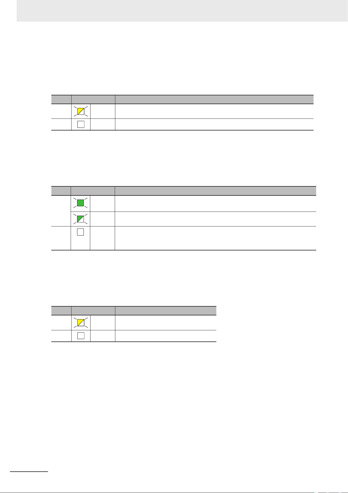
3 Specifications of Configuration Units
BUSY Indicator
l
The BUSY indicator shows the status of access to the built-in non-volatile memory of Communication Control Unit
The following table lists the possible states for this indicator and what they mean.
Color Status Meaning
Yellow Flashing Built-in non-volatile memory of Communication Control Unit access in progress.
--- Not lit Built-in non-volatile memory of Communication Control Unit access not in progress.
SD PWR Indicator
l
The SD PWR indicator shows the status of power supplied to the SD Memory Card of Communication Control Unit.
The following table lists the possible states for this indicator and what they mean.
.
Color Status Meaning
Green
--- Not lit Power feeding for the SD Memory Card is currently suspended, the SD Memory
SD BUSY Indicator
l
Lit Power is currently supplied to the SD Memory Card, and the SD Memory Card is
available for use.
Flashing A backup, restore or verification operation is in progress.
Card is not inserted, or the file format of the inserted SD Memory Card is not supported.
The SD BUSY indicator shows the status of access to the SD Memory Card of Communication
Control Unit
.
The following table lists the possible states for this indicator and what they mean.
Color Status Meaning
Yellow Flashing SD Memory Card access in progress.
--- Not lit SD Memory Card access not in progress.
3-16
NX-series Safety Control Unit/Communication Control Unit User's Manual (Z395)
Page 91

3 Specifications of Configuration Units
Built-in EtherNet/IP Status Indicators (PORT1)
These indicators show the operation status of the built-in EtherNet/IP port (PORT1) of the Communication Control Unit
The meaning of the indicators is shown below.
NS Indicator
l
The following table lists the possible states for this indicator and what they mean.
Color Status Meaning
Green Lit CIP Connections are established.
Red Lit The same IP address is used more than once.
--- Not lit The main power is OFF or reset.
L/A Indicator
l
.
Flashing (at 1-s intervals) CIP Connections are not established.
Flashing (at 1-s intervals) A communications error occurred.
3-1 Communication Control Unit
3
3-1-5 Indicators
The following table lists the possible states for this indicator and what they mean.
Color Status Meaning
Yellow Lit The link was established.
Flashing The link was established and data communications are in progress.
--- Not lit The link was not established.
• The cable was not connected
• The main power is OFF or reset
NX-series Safety Control Unit/Communication Control Unit User's Manual (Z395)
3-17
Page 92

3 Specifications of Configuration Units
Built-in EtherNet/IP Status Indicators (PORT2)
These indicators show the operation status of the built-in EtherNet/IP port (PORT2) of the Communication Control Unit
The meaning of the indicators is shown below.
NS Indicator
l
The following table lists the possible states for this indicator and what they mean.
Color Status Meaning
Green Lit CIP Connections are established.
.
Flashing (at 1-s intervals) CIP Connections are not established.
Red Lit The same IP address is used more than once.
Flashing (at 1-s intervals) A communications error occurred.
--- Not lit The main power is OFF or reset.
L/A 2A Indicator
l
The following table lists the possible states for this indicator and what they mean.
Color Status Meaning
Yellow Lit The link was established.
Flashing The link was established and data communications are in progress.
--- Not lit The link was not established.
• The cable was not connected
• The main power is OFF or reset
L/A 2B Indicator
l
The following table lists the possible states for this indicator and what they mean.
3-18
Color Status Meaning
Yellow
---
Lit The link was established.
Flashing The link was established and data communications are in progress.
Not lit The link was not established.
• The cable was not connected
• The main power is OFF or reset
NX-series Safety Control Unit/Communication Control Unit User's Manual (Z395)
Page 93
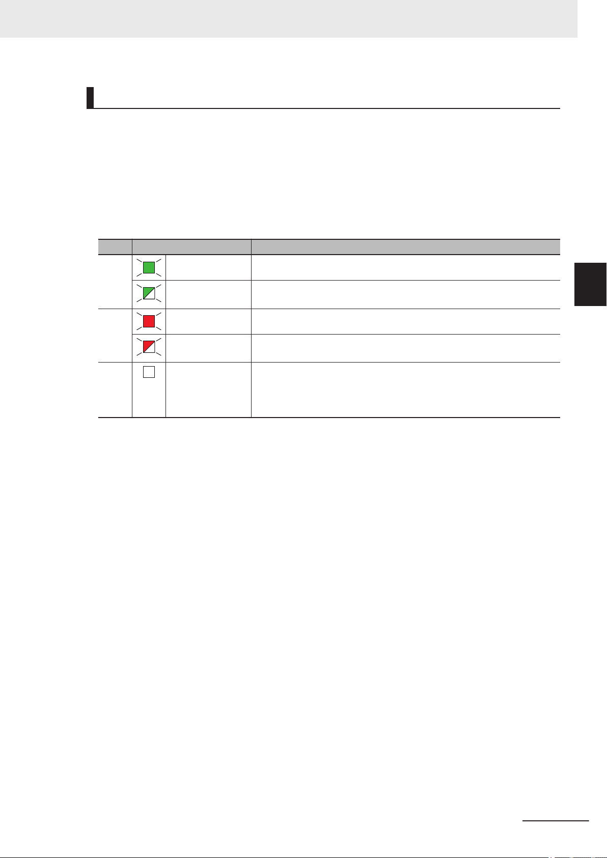
NX Bus Status Indicators
3 Specifications of Configuration Units
These indicators show the communications status of Communication Control Unit and NX Units.
The meaning of the indicators is shown below
TS Indicator
l
.
The following table lists the possible states for this indicator and what they mean.
Color Status Meaning
Green Lit The Unit is operating normally.
Flashing (at 1-s intervals)
Red
--- Not lit One of the following:
Lit A hardware error, WDT error, or other critical error has occurred.
Flashing (at 1-s intervals)
The initialization is in progress.
An NX bus communications error, I/O allocation information data error, or
other recoverable minor error caused by the NX bus has occurred.
• There is no Unit power supply
• Restarting the Unit
• W
aiting for initialization to start
3-1 Communication Control Unit
3
3-1-5 Indicators
NX-series Safety Control Unit/Communication Control Unit User's Manual (Z395)
3-19
Page 94
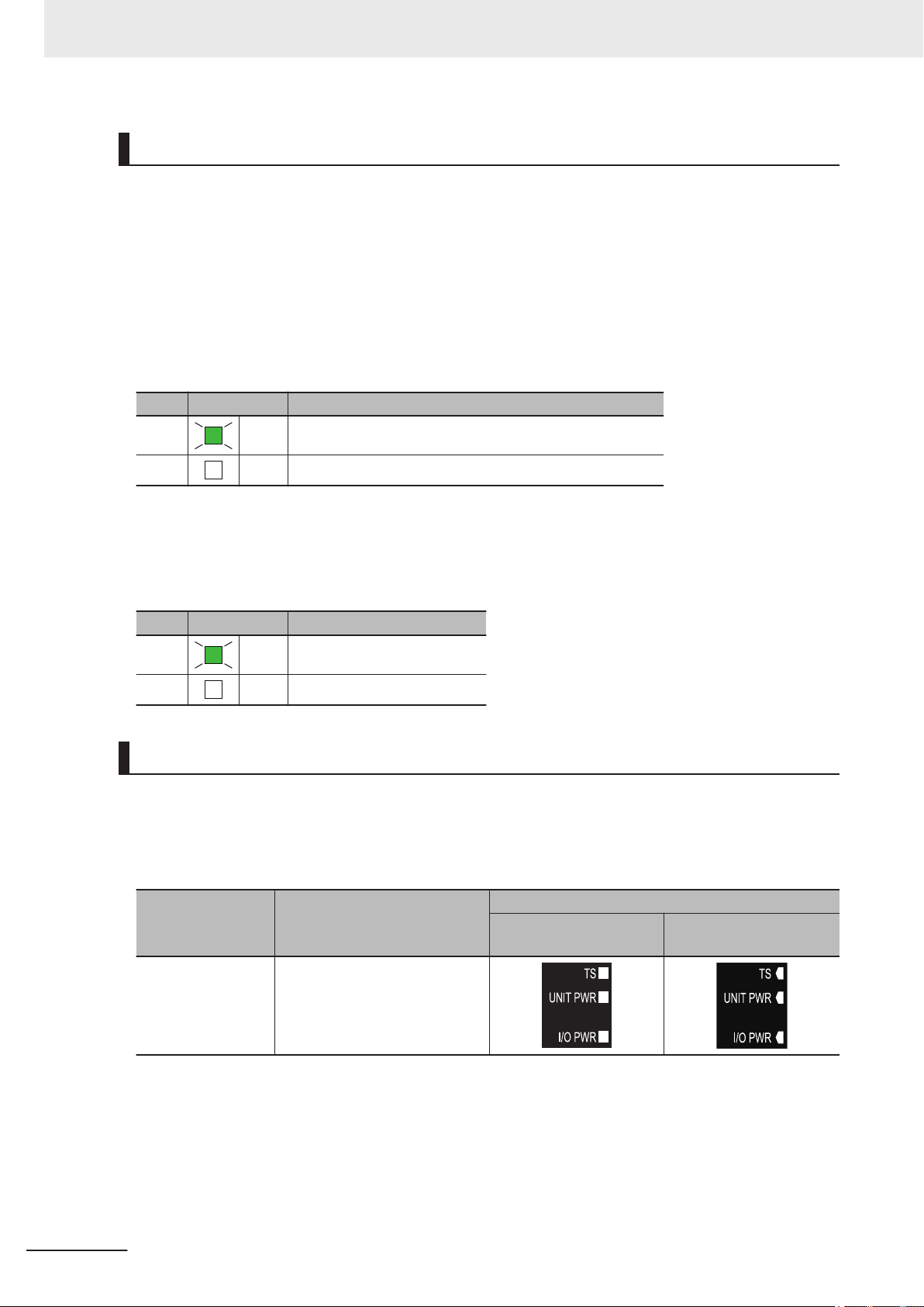
3 Specifications of Configuration Units
Power Status Indicators
These indicators show the power supply status of Communication Control Unit.
The meaning of the indicators is shown below
UNIT PWR Indicator
l
.
The UNIT PWR indicator displays the status of the Unit power supply.
The following table lists the possible states for this indicator and what they mean.
Color Status Meaning
Green Lit Power is currently supplied from the Unit power supply.
--- Not lit Power is currently not supplied from the Unit power supply.
I/O PWR Indicator
l
The I/O PWR indicator displays the status of I/O power supply.
The following table lists the possible states for this indicator and what they mean.
Color Status Meaning
Green
Lit The I/O power is supplied.
--- Not lit The I/O power is not supplied.
Differences in Appearance of the Indicators
The appearance of the indicators is different for the Unit with the lot number representing the date on
or before March 19, 2019, from that representing the date on or after March 20, 2019.
The following table shows how the appearance of the indicators is dif
ber.
Indicator Description
TS indicator
UNIT PWR indicator
I/O PWR indicator
The shape of the light emitting
parts is changed from a square
to a pentagon.
On or before March 19,
2019
ferent depending on the lot num-
Lot number
On or after March 20,
2019
3-20
NX-series Safety Control Unit/Communication Control Unit User's Manual (Z395)
Page 95
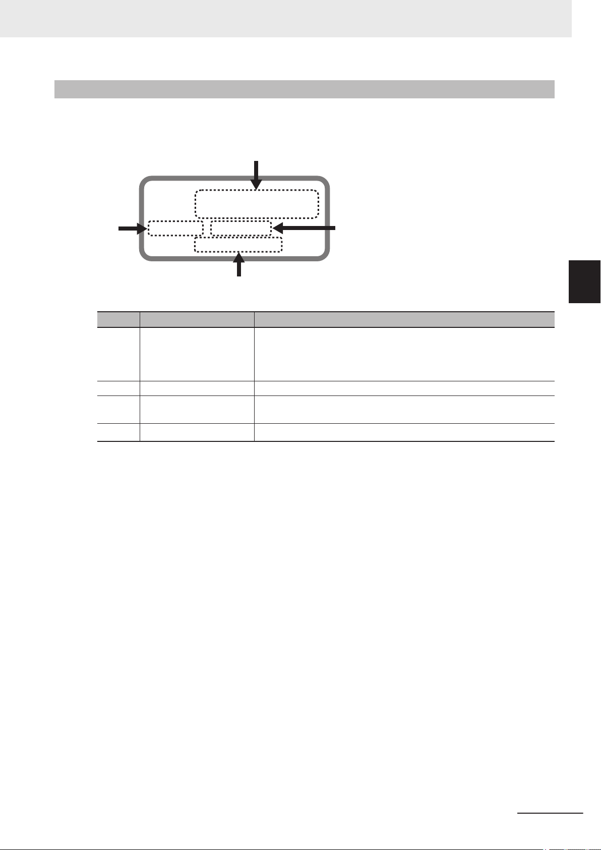
(A)
(B)
PORT1
: ££££££££££££
PORT2 : ££££££££££££
Ver.1.££ HW Rev. £
LOT No. DDMYY£ xxxx
(C)
(D)
3 Specifications of Configuration Units
3-1-6
ID Information Indication
ID Information of Communication Control Unit is given on the ID information indication on the left side
of the Unit.
Letter Name Function
(A) Lot number and serial
number
(B) Unit version Shows the unit version of the this Unit.
(C) MAC addresses Shows the MAC addresses of the built-in EtherNet/IP port (port 1 and
(D) Hardware revision
*1. The hardware revision is not displayed for the Unit that the hardware revision is in blank.
Shows the lot number and the serial number of the this Unit.
DDMYY
For M, 1: January to 9: September, X: October, Y: November, Z: December.
port 2) on the this Unit.
Shows the hardware revision of the this Unit.
: Lot number, £: For use by OMRON, SSSS: Serial number
*1
3-1 Communication Control Unit
3
3-1-6 ID Information Indication
NX-series Safety Control Unit/Communication Control Unit User's Manual (Z395)
3-21
Page 96

3 Specifications of Configuration Units
3-2
3-2-1
Safety CPU Unit
This section describes the models and specifications of the Safety CPU Units as well as the names
and functions of the parts.
Models and Specifications
The Safety CPU Unit specifications are described below.
Models
The following table specifies the list of Safety CPU Unit models.
Maximum
Model
NX-SL5500 1,024 points 2,048 KB 128 Free-Run refreshing
NX-SL5700 2,032 points 4,096 KB 254 Free-Run refreshing
number of
safety I/O
points
Program ca-
pacity
Number of
safety I/O con-
nections
I/O refreshing method
General Specifications
This section provides the general specifications of the Safety CPU Unit.
Item Specification
Enclosure Mounted in a panel (open)
Grounding method Ground to 100 Ω or less
Operating environment Ambient operating tem-
perature
Ambient operating humidity
Atmosphere Must be free from corrosive gases.
Ambient storage temperature
Altitude 2,000 m max.
Pollution degree 2 or less: Meets IEC 61010-2-201
Noise immunity Conforms to IEC 61131-2, 2 kV (power supply line)
Insulation class CLASS III (SELV)
Overvoltage category Category II: Meets IEC 61010-2-201
EMC immunity level Zone B
Vibration resistance Conforms to IEC 60068-2-6
Shock resistance Conforms to IEC 60068-2-27
Installation method DIN Track (IEC 60715 TH35-7.5/TH35-15)
0 to 55°C
10% to 95% (with no condensation or icing)
−25 to 70°C (with no condensation or icing)
5 to 8.4 Hz with amplitude of 3.5 mm
8.4 to 150 Hz, acceleration of 9.8 m/s
100 min. in each X, Y
10 min. each = 100 min. total)
147 m/s2, 3 times in each X, Y
, and Z directions (10 sweeps of
2
, and Z directions
3-22
NX-series Safety Control Unit/Communication Control Unit User's Manual (Z395)
Page 97

3 Specifications of Configuration Units
Individual Specifications
This section provides the individual specifications of the Safety CPU Unit.
Datasheet Items for Safety CPU Unit
l
The following table gives the meaning of the datasheet items for the Safety CPU Unit.
Item Description
Maximum number of safety
I/O points
Program capacity This is the capacity of the safety programs in the Unit.
Number of safety I/O connec-
*1
tions
Number of CIP Safety origi-
nator connections
Number of CIP Safety target
connections
Number of originators that
can be connected with a multi-cast connection
Number of FSoE master connections
I/O refreshing method The I/O refreshing methods that are used by the Unit.
External connection terminals
Indicators The type of indicators on the Unit and the layout of those indicators.
Hardware switch settings It is the type and layout of hardware switches for the Unit.
Dimensions (mm) These are the external dimensions of the Unit. The dimensions are given in
I/O power supply method The method for supplying I/O power for the Unit. The supply method is deter-
Current capacity of I/O power
supply terminal
NX Unit power consumption The power consumption of the NX Unit power supply of the Unit.
Current consumption from
I/O power supply
Weight The weight of the Unit.
Installation orientation and
restrictions
*1. Refer to 6-1-5 Calculating the Number of Connections on page 6-9 for how to calculate the number of
connections.
*2. The number of CIP Safety connections that can be actually set depends on the maximum number of routa-
ble CIP Safety connections of the Communication Control Unit
For NX-CSG320, the maximum number of routable CIP Safety connections is 254.
*2
*2
This is the number of safety I/O points that Safety CPU Unit can control.
This is the maximum number of Safety I/O connections that can be set to this
Unit. The value is the total number of CIP Safety originator connections, CIP
Safety target connections, and FSoE master connections.
This is the maximum number of CIP Safety originator connections that can be
set to this Unit.
This is the maximum number of CIP Safety target connections that can be set
to this Unit.
When this unit is a CIP Safety target, it is the number of CIP Safety originators that can be connected with a multi-cast connection by a single CIP Safety target connection.
It is the maximum number of FSoE master connections that can be configured to this unit.
The type of terminal block and connector that is used for connecting the Unit.
This specification includes the number of terminals for a screwless clamping
terminal block.
the form W × H × D. The dimensions are given in "millimeters
mined for each Unit. The power can be supplied either from the NX bus or
from an external source.
The current capacity of the I/O power supply terminals (IOV/IOG) of the Unit.
Do not exceed this value when supplying the I/O power to the connected external devices.
The current consumption from I/O power supply of the Unit. This value does
not include the load current of any external connection loads or the current
consumption of any connected external devices.
This is the installation orientation of the Unit. Any restrictions to specifications
that result from the installation orientation are also given.
.
".
3-2 Safety CPU Unit
3
3-2-1 Models and Specifications
NX-series Safety Control Unit/Communication Control Unit User's Manual (Z395)
3-23
Page 98

Seven-segment indicator
[TS] indicator, [NS] indicator, [FS] indicator
[P ERR] indicator, [RUN] indicator,
[VALID] indicator, [DEBUG] indicator
3 Specifications of Configuration Units
NX-SL5500
l
Item Specification
Maximum number of safety I/O
points
Program capacity 2,048 KB
Number of safety I/O connections
Number of CIP Safety originator
connections
Number of CIP Safety target connections
Number of originators that can
be connected with a multi-cast
connection
Number of FSoE master connections
I/O refreshing method Free-Run refreshing
External connection terminals None
Indicators [TS] indicator, [NS] indicator, [FS] indicator, [P ERR] indicator, [RUN] indi-
1,024 points
128
128
4
8
128
, [VALID] indicator, [DEBUG] indicator, seven-segment indicator
cator
Hardware switch settings [SERVICE] switch, [SETTING] switch
Dimensions (mm) 30 × 100 × 71 mm (W × H × D)
I/O power supply method Not supplied.
Current capacity of I/O power
supply terminal
NX Unit power consumption
Current consumption from I/O
power supply
Weight 130 g max.
3-24
No I/O power supply terminals
*1
3.35 W max.
No consumption
NX-series Safety Control Unit/Communication Control Unit User's Manual (Z395)
Page 99

Seven-segment indicator
[TS] indicator, [NS] indicator, [FS] indicator
[P ERR] indicator, [RUN] indicator,
[VALID] indicator, [DEBUG] indicator
3 Specifications of Configuration Units
Item Specification
Installation orientation and re-
strictions
*1. The cable length for the Units (Communication Control Unit and the Power Supply Unit for NX Units) that
*2. Only NX102 CPU Units and Communication Control Units can be connected. NX1P2 CPU Units or Commu-
NX-SL5700
l
Maximum number of safety
I/O points
Program capacity 4,096 KB
Number of safety I/O connections
Number of CIP Safety originator connections
Number of CIP Safety target
connections
Number of originators that
can be connected with a multi-cast connection
Number of FSoE master connections
I/O refreshing method Free-Run refreshing
External connection terminals
Indicators [TS] indicator, [NS] indicator, [FS] indicator, [P ERR] indicator, [RUN] indica-
*2
supply power to the corresponding Unit must be up to 20 m.
nications Coupler Units cannot be connected.
Item Specification
Installation orientation: Upright installation
Restriction: None.
2,032 points
254
254
4
8
254
None
, [VALID] indicator, [DEBUG] indicator, seven-segment indicator
tor
3-2 Safety CPU Unit
3
3-2-1 Models and Specifications
Hardware switch settings [SERVICE] switch, [SETTING] switch
NX-series Safety Control Unit/Communication Control Unit User's Manual (Z395)
Dimensions (mm) 30 × 100 × 71 (W × H × D)
3-25
Page 100

(D)
(D)
(E)
(C)
(I)
(F
)
(E)
(A)
(G)
(H)
(C)
(C)
(B)
(E)
(B)
(B)
(G)
(H)
(E)
3 Specifications of Configuration Units
Item Specification
I/O power supply method Not supplied.
Current capacity of I/O power
supply terminals
NX UnitPower consumption
Current consumption from
I/O power supply
Weight 130 g max.
Installation orientation and
restrictions
*1. The cable length for the Units (Communication Control Unit and Power Supply Unit for NX Units) that supply
power to the corresponding Unit must be up to 20 m.
*2. Only NX102 CPU Units and Communication Control Units can be connected. NX1P2 CPU Units or Commu-
nications Coupler Units cannot be connected.
*2
No I/O power supply terminals
*1
3.35 W
No consumption
Installation orientation: Upright installation
Restriction: None.
3-2-2
Part Names and Functions
This section describes the names and functions of the Safety CPU Unit components.
3-26
Let-
ter
(A) Marker attachment loca-
tions
(B) Protrusions for removing
the Unit
(C) DIN Track mounting
hook
(D) NX bus connector This is the NX-series bus connector.
(E) Unit hookup guides These guides are used to connect two Units.
Name Function
The locations where markers are attached. The markers made by OMRON
are installed for the factory setting. Commercially available markers can also
be installed.
Refer to 5-2-7 Attaching Markers on page 5-20
The protrusions to hold when removing the Unit.
This hook is used to mount the NX Unit to a DIN Track.
NX-series Safety Control Unit/Communication Control Unit User's Manual (Z395)
.
 Loading...