

Page 1

Machine Automation Controller
NJ/NX-series
CPU Unit
OPC UA
User’s Manual
NJ501-100
NX102-
NX701-1
W588-E1-04
Page 2

NOTE
All rights reserved. No part of this publication may be reproduced, stored in a retrieval system, or transmitted, in
any form, or by any means, mechanical, electronic, photocopying, recording, or otherwise, without the prior
written permission of OMRON.
No patent liability is assumed with respect to the use of the information contained herein. Moreover, because
OMRON is constantly striving to improve its high-quality products, the information contained in this manual is
subject to change without notice. Every precaution has been taken in the preparation of this manual. Nevertheless, OMRON assumes no responsibility for errors or omissions. Neither is any liability assumed for damages
resulting from the use of the information contained in this publication.
Trademarks
• Sysmac and SYSMAC are trademarks or registered trademarks of OMRON Corporation in Japan and other
countries for OMRON factory automation products.
• Microsoft, Windows, Excel, and Visual Basic are either registered trademarks or trademarks of Microsoft Corporation in the United States and other countries.
• EtherCAT® is registered trademark and patented technology, licensed by Beckhoff Automation GmbH, Germany.
• ODVA, CIP, CompoNet, DeviceNet, and EtherNet/IP are trademarks of ODVA.
• The SD and SDHC logos are trademarks of SD-3C, LLC.
Other company names and product names in this document are the trademarks or registered trademarks of their
respective companies.
Copyrights
Microsoft product screen shots reprinted with permission from Microsoft Corporation.
Page 3

Introduction
Thank you for purchasing an NJ/NX-series CPU Unit.
This manual contains information that is necessary to use the OPC UA with the NJ/NX-series CPU
Unit. Please read this manual and make sure you understand the functionality and performance of the
NJ/NX-series CPU Unit before you attempt to use it in a control system.
Keep this manual in a safe place where it will be available for reference during operation.
Intended Audience
This manual is intended for the following personnel, who must also have knowledge of electrical systems (an electrical engineer or the equivalent).
• Personnel in charge of introducing FA systems.
• Personnel in charge of designing FA systems.
• Personnel in charge of installing and maintaining FA systems.
• Personnel in charge of managing FA systems and facilities.
For programming, this manual is intended for personnel who understand the programming language
specifications in international standard IEC 61131-3 or Japanese standard JIS B 3503.
Introduction
Applicable Products
This manual covers the following products.
• NJ-series CPU Units NJ501-100 (Unit version 1.17 or later)
• NX-series CPU Units NX102- (Unit version 1.30 or later)
• NX-series CPU Units NX701-1 (Unit version 1.24 or later)
• Sysmac Studio SYSMAC-SE2
(NJ501-100: version 1.21 or higher, NX102-00: version 1.23 or higher,
NX102-20: version 1.24 or higher, NX701-1: version 1.44 or higher)
Part of the specifications and restrictions for the CPU Units are given in other manuals. Refer to Rele-
vant Manuals on page 2 and Related Manuals on page 17.
NJ/NX-series CPU Unit OPC UA User’s Manual (W588)
1
Page 4

Relevant Manuals
Relevant Manuals
The following table provides the relevant manuals for the NJ/NX-series CPU Units.
Read all of the manuals that are relevant to your system configuration and application before you use
the NJ/NX-series CPU Unit.
The built-in EtherNet/IP port in the NJ/NX-series CPU Unit is used for this product.
For details on how to use the built-in EtherNet/IP port, refer to the NJ/NX-series CPU Unit Built-in Eth-
erNet/IP Port User’s Manual (Cat. No. W506)
Most operations are performed from the Sysmac Studio Automation Software. Refer to the Sysmac Stu-
dio Version 1 Operation Manual (Cat. No. W504) for information on the Sysmac Studio.
NX-series CPU Unit
Hardware User’s
Manual
Purpose of use
Manual
Basic information
NX-series NX102 CPU
Unit Hardware User’s
NJ-series CPU Unit
Hardware User’s
Manual
Manual
NJ/NX-series CPU Unit
Software User’s Manual
NJ/NX-series
Instructions Reference
Manual
NJ/NX-series CPU Unit
Motion Control User’s
Manual
NJ/NX-series Motion
Control Instructions
Reference Manual
User’s Manual
NJ/NX-series CPU Unit
Built-in EtherCAT Port
NJ/NX-series CPU Unit
Built-in EtherNet/IP Port
User’s Manual
NJ-series CPU Unit
OPC UA User’s Manual
NJ/NX-series
Troubleshooting
Manual
Introduction to NX701 CPU Units
Introduction to NX102 CPU Units
Introduction to NJ-series Controllers
Setting devices and hardware
Using motion control
Using EtherCAT
Using EtherNet/IP
Software settings
Using motion control
Using EtherCAT
Using EtherNet/IP
Using OPC UA
Writing the user program
Using motion control
Using EtherCAT
Using EtherNet/IP
Programming error processing
Using OPC UA
Testing operation and debugging
Using motion control
Using EtherCAT
Using EtherNet/IP
Using OPC UA
Learning about error management and
corrections
Maintenance
*1
Using motion control
Using EtherCAT
Using EtherNet/IP
*1 Refer to the NJ/NX-series Troubleshooting Manual (Cat. No. W503) for the error management concepts and an overview
of the error items. Refer to the manuals that are indicated with triangles for details on errors for the corresponding Units.
2
NJ/NX-series CPU Unit OPC UA User’s Manual (W588)
Page 5
Manual Structure
4-9
4 Installation and Wiring
NJ-series CPU Unit Hardware User’s Manual (W500)
stinU gnitnuoM 3-4
4
stnenopmoC rellortnoC gnitcennoC 1-3-4
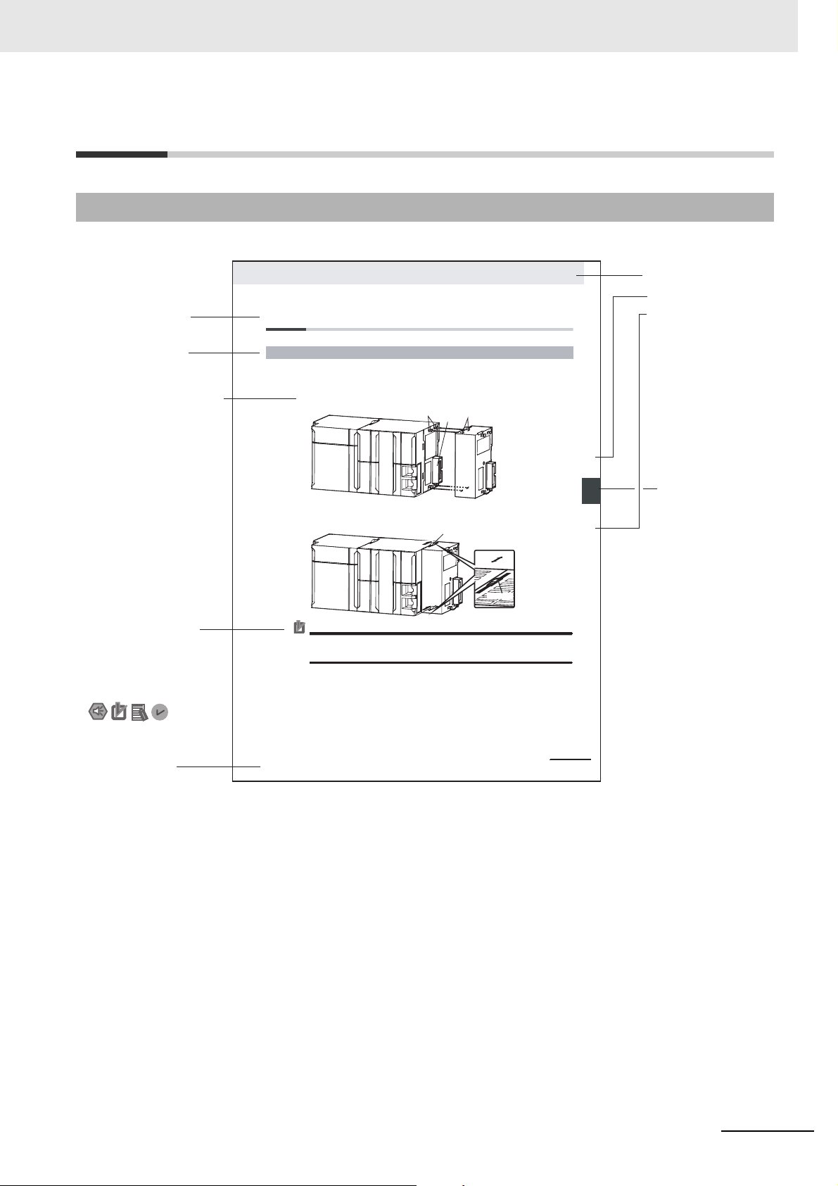
4-3 Mounting Units
The Units that make up an NJ-series Controller can be connected simply by pressing the Units together
and locking the sliders by moving them toward the back of the Units. The End Cover is connected in the
same way to the Unit on the far right side of the Controller.
1 Join the Units so that the connectors fit exactly.
2 The yellow sliders at the top and bottom of each Unit lock the Units together. Move the sliders
toward the back of the Units as shown below until they click into place.
Precautions for Correct UsePrecautions for Correct Use
4-3-1 Connecting Controller Components
Connector
Hook
Hook holes
Slider
Lock
Release
Move the sliders toward the back
until they lock into place.
Level 1 heading
Level 2 heading
Level 3 heading
Level 2 heading
A step in a procedure
Manual name
Special information
Level 3 heading
Page tab
Gives the current
headings.
Indicates a procedure.
Icons indicate
precautions, additional
information, or reference
information.
Gives the number
of the main section.
This illustration is provided only as a sample. It may not literally appear in this manual.
The sliders on the tops and bottoms of the Power Supply Unit, CPU Unit, I/O Units, Special I/O
Units, and CPU Bus Units must be completely locked (until they click into place) after connecting
the adjacent Unit connectors.
Page Structure
The following page structure is used in this manual.
Manual Structure
NJ/NX-series CPU Unit OPC UA User’s Manual (W588)
3
Page 6

Manual Structure
Special Information
Special information in this manual is classified as follows:
Precautions for Safe Use
Precautions on what to do and what not to do to ensure safe usage of the product.
Precautions for Correct Use
Precautions on what to do and what not to do to ensure proper operation and performance.
Additional Information
Additional information to read as required.
This information is provided to increase understanding or make operation easier.
Version Information
Information on differences in specifications and functionality for CPU Units with different unit versions
and for different versions of the Sysmac Studio is given.
Note References are provided to more detailed or related information.
Precaution on Terminology
• In this manual, built-in EtherNet/IP port refers to the following port.
- Built-in EtherNet/IP port of the NJ-series CPU Units NJ501-100
- Built-in EtherNet/IP port (PORT 1) of the NX-series CPU Units NX102-
- Built-in EtherNet/IP port (PORT 1) of the NX-series CPU Units NX701-1
• In this manual, download refers to transferring data from the Sysmac Studio to the physical Controller
and upload refers to transferring data from the physical Controller to the Sysmac Studio.
For the Sysmac Studio, synchronization is used to both upload and download data. Here, synchro-
nize means to automatically compare the data for the Sysmac Studio on the computer with the data
in the physical Controller and transfer the data in the direction that is specified by the user.
4
NJ/NX-series CPU Unit OPC UA User’s Manual (W588)
Page 7

Sections in this Manual
1A
I2
3
4
5
6
7
8
9
1A
I2
3
4
5
6
7
8
9
Overview of OPC UA
Server Function
Structure of the OPC
UA Server
Appendices
Index
Settings of the OPC UA Server
Starting and Checking the Status of
the OPC UA Server
Security Function of OPC UA Server
Execution Log Functions
Connecting from the OPC UA Client and
Reading/Writing Variables
Other Functions
Troubleshooting
Sections in this Manual
NJ/NX-series CPU Unit OPC UA User’s Manual (W588)
5
Page 8

CONTENTS
CONTENTS
Introduction ...............................................................................................................1
Relevant Manuals......................................................................................................2
Manual Structure.......................................................................................................3
Sections in this Manual ............................................................................................5
Terms and Conditions Agreement .........................................................................10
Safety Precaution.................................................................................................... 12
Precautions for Safe Use........................................................................................13
Precautions for Correct Use...................................................................................14
Regulations and Standards....................................................................................15
Versions ...................................................................................................................16
Related Manuals...................................................................................................... 17
Terminology.............................................................................................................19
Revision History...................................................................................................... 21
Section 1 Overview of OPC UA Server Function
1-1 Overview and Features ........................................................................................................... 1-2
1-1-1 Overview .....................................................................................................................................1-2
1-1-2 System Configuration..................................................................................................................1-2
1-1-3 Features...................................................................................................................................... 1-2
1-2 Specifications .......................................................................................................................... 1-4
1-2-1 List of Supported CPU Units .......................................................................................................1-4
1-2-2 Function Specifications ...............................................................................................................1-5
1-3 OPC UA Server Procedures.................................................................................................... 1-7
1-3-1 Overall Procedure ....................................................................................................................... 1-7
1-3-2 Procedure Details........................................................................................................................ 1-8
Section 2 Structure of the OPC UA Server
2-1 Internal Structure of the Overall OPC UA Communications System.................................. 2-2
2-1-1 Overview .....................................................................................................................................2-2
2-1-2 Details .........................................................................................................................................2-3
2-2 Overview of the Security Function of the OPC UA Server................................................... 2-5
Section 3 Settings of the OPC UA Server
3-1 Controller Setup ...................................................................................................................... 3-2
3-1-1 IP Address Settings of the Built-in EtherNet/IP Port....................................................................3-2
6
NJ/NX-series CPU Unit OPC UA User’s Manual (W588)
Page 9

CONTENTS
3-2 OPC UA Settings...................................................................................................................... 3-3
3-2-1 Overview of OPC UA Settings .................................................................................................... 3-3
3-2-2 OPC UA Server Settings............................................................................................................. 3-7
3-2-3 When necessary to cycle the power supply to the Controller or reset the Controller ............... 3-10
3-2-4 Automatic Generation of the Server Certificate ........................................................................ 3-10
3-2-5 Setting and Displaying the Certificate........................................................................................3-11
3-2-6 Security Settings....................................................................................................................... 3-22
3-2-7 Server Status............................................................................................................................ 3-25
3-2-8 Displaying the Operation Logs.................................................................................................. 3-25
3-2-9 Operations for the OPC UA Settings ........................................................................................ 3-26
3-3 Creating Variables for OPC UA Communications .............................................................. 3-27
3-3-1 Global Variables Published to OPC UA Communications ........................................................ 3-27
3-3-2 Adding or Deleting Network-published Variables...................................................................... 3-28
Section 4 Starting and Checking the Status of the OPC UA Server
4-1 Starting or Stopping the OPC UA Server .............................................................................. 4-2
4-1-1 How to Start or Stop the OPC UA Server ................................................................................... 4-2
4-1-2 Conditions under Which the OPC UA Server Cannot be Started ............................................... 4-3
4-1-3 Conditions under Which the OPC UA Server Stops ................................................................... 4-3
4-1-4 Operation of the OPC UA Service Function in each State of the CPU Unit................................ 4-4
4-2 Checking the Status of the OPC UA Server .......................................................................... 4-5
4-2-1 Checking Based on OPC UA Server Status of the Sysmac Studio ............................................ 4-5
4-2-2 Checking Based on the Event Log ............................................................................................. 4-7
4-2-3 Checking Based on the Execution Log....................................................................................... 4-7
4-2-4 Operating Status of the OPC UA Server..................................................................................... 4-7
4-2-5 Conditions for Reconfiguring the OPC UA Server ...................................................................... 4-9
Section 5 Security Function of OPC UA Server
5-1 Details of the Connection Authentication Function of the OPC UA Server ....................... 5-2
5-1-1 Application Authentication........................................................................................................... 5-2
5-1-2 User Authentication..................................................................................................................... 5-5
5-2 Details of the Message Security Function ............................................................................ 5-7
5-2-1 Signature and Encryption ........................................................................................................... 5-7
5-2-2 OPC UA Security Mode and Policy............................................................................................. 5-7
Section 6 Connecting from the OPC UA Client and
Reading/Writing Variables
6-1 Connecting from the OPC UA Client...................................................................................... 6-2
6-1-1 Specifying the URL of the Target OPC UA Server...................................................................... 6-2
6-1-2 Connecting to the Target OPC UA Server .................................................................................. 6-2
6-2 Reading/Writing Variables from the OPC UA Client ............................................................. 6-3
6-2-1 Address Space of the NJ/NX-series Controller........................................................................... 6-3
6-2-2 Reading/Writing the Variables of the CPU Unit .......................................................................... 6-5
Section 7 Execution Log Functions
7-1 Execution Logs........................................................................................................................ 7-2
7-1-1 Overview..................................................................................................................................... 7-2
7-1-2 How to Use the Execution Log ................................................................................................... 7-4
7-1-3 Setting the Execution Log........................................................................................................... 7-4
7-1-4 Checking the Execution Log....................................................................................................... 7-4
7-1-5 Execution Log File Specifications............................................................................................... 7-5
NJ/NX-series CPU Unit OPC UA User’s Manual (W588)
7
Page 10

CONTENTS
7-1-6 Format of Records ......................................................................................................................7-5
7-1-7 Examples of Records in Execution Log File.............................................................................. 7-11
7-2 Checking the Execution Log ................................................................................................ 7-13
7-2-1 How to Check the Execution Log..............................................................................................7-13
7-2-2 Checking Logs in the Operation Log Window in the Sysmac Studio ........................................7-13
7-2-3 Checking Logs with the SD Memory Card ................................................................................7-16
7-2-4 Checking Logs by Using FTP Client Software ..........................................................................7-16
7-3 OPC UA Server Shutdown Function .................................................................................... 7-17
7-3-1 Overview ...................................................................................................................................7-17
7-3-2 Shutdown System ..................................................................................................................... 7-17
7-3-3 How to Execute the Shutdown Function ...................................................................................7-18
7-3-4 How to Check the Shutdown of the OPC UA Server.................................................................7-18
7-4 SD Memory Card Operations................................................................................................ 7-19
7-4-1 Conditions for Saving Execution Log Files to the SD Memory Card......................................... 7-19
7-4-2 Directories Used for the OPC UA Server ..................................................................................7-19
7-4-3 Execution Log Operation when Replacing the SD Memory Card .............................................7-20
7-4-4 Approximate Work Time for SD Memory Card Replacement....................................................7-20
7-4-5 Replacement Timing of SD Memory Card.................................................................................7-20
Section 8 Other Functions
8-1 The Sysmac Studio Operation Authority Verification Related to the OPC UA Server ...... 8-2
8-2 Backup and Restore Functions Related to the OPC UA Server.......................................... 8-4
8-2-1 Backup Function ......................................................................................................................... 8-5
8-2-2 Restoration and Verification ........................................................................................................8-6
8-2-3 Compatibility between Backup-related Files ...............................................................................8-7
8-2-4 How to Replace the CPU Unit in Relation to the OPC UA Server............................................... 8-8
8-3 Clear All Memory Function Related to the OPC UA Server ................................................. 8-9
Section 9 Troubleshooting
9-1 Overview of Troubleshooting ................................................................................................. 9-2
Section A Appendices
A-1 Task Design Procedure ...........................................................................................................A-2
A-1-1 Startup Time of the OPC UA Server (Reference Values)............................................................A-2
A-1-2 Guidelines for System Service Execution Time Ratio.................................................................A-5
A-1-3 Checking the System Service Execution Time Ratio ..................................................................A-7
A-2 OPC UA Instruction .................................................................................................................A-9
A-2-1 OPCUA_Shutdown (Shutdown OPC UA Function).....................................................................A-9
A-2-2 Variables .....................................................................................................................................A-9
A-2-3 Related System-defined Variables............................................................................................A-10
A-2-4 Related Error Codes .................................................................................................................A-10
A-2-5 Function ....................................................................................................................................A-10
A-2-6 Precautions for Correct Use......................................................................................................A-10
A-2-7 Additional Information ...............................................................................................................A-11
A-2-8 Sample Programming ...............................................................................................................A-11
A-3 When CA-signed Client Certificates Supported .................................................................A-13
A-3-1 Overview ...................................................................................................................................A-13
A-3-2 Settings .....................................................................................................................................A-14
A-3-3 Related Operations Performed from OPC UA Settings in the Sysmac Studio..........................A-14
A-4 List of Related System-defined Variables ...........................................................................A-18
A-4-1 System-defined Variables for the Overall NJ/NX-series Controller (No Category) ...................A-18
A-5 Version Information...............................................................................................................A-19
8
NJ/NX-series CPU Unit OPC UA User’s Manual (W588)
Page 11

CONTENTS
Index
A-5-1 Relationship between Unit Versions and OPC UA Standard Versions ..................................... A-19
A-5-2 Relationship between Unit Versions and the Sysmac Studio Versions ....................................A-19
NJ/NX-series CPU Unit OPC UA User’s Manual (W588)
9
Page 12

Terms and Conditions Agreement
Terms and Conditions Agreement
Warranty, Limitations of Liability
Warranties
Exclusive Warranty
Omron’s exclusive warranty is that the Products will be free from defects in materials and workmanship for a period of twelve months from the date of sale by Omron (or such other period expressed in
writing by Omron). Omron disclaims all other warranties, express or implied.
Limitations
OMRON MAKES NO WARRANTY OR REPRESENTATION, EXPRESS OR IMPLIED, ABOUT
NON-INFRINGEMENT, MERCHANTABILITY OR FITNESS FOR A PARTICULAR PURPOSE OF
THE PRODUCTS. BUYER ACKNOWLEDGES THAT IT ALONE HAS DETERMINED THAT THE
PRODUCTS WILL SUITABLY MEET THE REQUIREMENTS OF THEIR INTENDED USE.
Omron further disclaims all warranties and responsibility of any type for claims or expenses based
on infringement by the Products or otherwise of any intellectual property right.
Buyer Remedy
Omron’s sole obligation hereunder shall be, at Omron’s election, to (i) replace (in the form originally
shipped with Buyer responsible for labor charges for removal or replacement thereof) the non-complying Product, (ii) repair the non-complying Product, or (iii) repay or credit Buyer an amount equal
to the purchase price of the non-complying Product; provided that in no event shall Omron be
responsible for warranty, repair, indemnity or any other claims or expenses regarding the Products
unless Omron’s analysis confirms that the Products were properly handled, stored, installed and
maintained and not subject to contamination, abuse, misuse or inappropriate modification. Return of
any Products by Buyer must be approved in writing by Omron before shipment. Omron Companies
shall not be liable for the suitability or unsuitability or the results from the use of Products in combination with any electrical or electronic components, circuits, system assemblies or any other materials or substances or environments. Any advice, recommendations or information given orally or in
writing, are not to be construed as an amendment or addition to the above warranty.
See http://www.omron.com/global/ or contact your Omron representative for published information.
Limitation on Liability; Etc
OMRON COMPANIES SHALL NOT BE LIABLE FOR SPECIAL, INDIRECT, INCIDENTAL, OR CONSEQUENTIAL DAMAGES, LOSS OF PROFITS OR PRODUCTION OR COMMERCIAL LOSS IN ANY
WAY CONNECTED WITH THE PRODUCTS, WHETHER SUCH CLAIM IS BASED IN CONTRACT,
WARRANTY, NEGLIGENCE OR STRICT LIABILITY.
Further, in no event shall liability of Omron Companies exceed the individual price of the Product on
which liability is asserted.
10
NJ/NX-series CPU Unit OPC UA User’s Manual (W588)
Page 13

Application Considerations
Suitability of Use
Omron Companies shall not be responsible for conformity with any standards, codes or regulations
which apply to the combination of the Product in the Buyer’s application or use of the Product. At
Buyer’s request, Omron will provide applicable third party certification documents identifying ratings
and limitations of use which apply to the Product. This information by itself is not sufficient for a complete determination of the suitability of the Product in combination with the end product, machine, system, or other application or use. Buyer shall be solely responsible for determining appropriateness of
the particular Product with respect to Buyer’s application, product or system. Buyer shall take application responsibility in all cases.
NEVER USE THE PRODUCT FOR AN APPLICATION INVOLVING SERIOUS RISK TO LIFE OR
PROPERTY OR IN LARGE QUANTITIES WITHOUT ENSURING THAT THE SYSTEM AS A WHOLE
HAS BEEN DESIGNED TO ADDRESS THE RISKS, AND THAT THE OMRON PRODUCT(S) IS
PROPERLY RATED AND INSTALLED FOR THE INTENDED USE WITHIN THE OVERALL EQUIPMENT OR SYSTEM.
Terms and Conditions Agreement
Programmable Products
Omron Companies shall not be responsible for the user’s programming of a programmable Product, or
any consequence thereof.
Disclaimers
Performance Data
Data presented in Omron Company websites, catalogs and other materials is provided as a guide for
the user in determining suitability and does not constitute a warranty. It may represent the result of
Omron’s test conditions, and the user must correlate it to actual application requirements. Actual performance is subject to the Omron’s Warranty and Limitations of Liability.
Change in Specifications
Product specifications and accessories may be changed at any time based on improvements and other
reasons. It is our practice to change part numbers when published ratings or features are changed, or
when significant construction changes are made. However, some specifications of the Product may be
changed without any notice. When in doubt, special part numbers may be assigned to fix or establish
key specifications for your application. Please consult with your Omron’s representative at any time to
confirm actual specifications of purchased Product.
Errors and Omissions
Information presented by Omron Companies has been checked and is believed to be accurate; however, no responsibility is assumed for clerical, typographical or proofreading errors or omissions.
NJ/NX-series CPU Unit OPC UA User’s Manual (W588)
11
Page 14

Safety Precaution
Safety Precaution
Refer to the following manuals for safety precautions.
• NX-series CPU Unit Hardware User’s Manual (Cat. No. W535)
• NJ-series CPU Unit Hardware User’s Manual (Cat. No. W500)
• NX-series NX102 CPU Unit Hardware User's Manual (Cat. No. W593)
• Sysmac Studio Version 1 Operation Manual (Cat. No. W504)
12
NJ/NX-series CPU Unit OPC UA User’s Manual (W588)
Page 15

Precautions for Safe Use
This section describes the precautions for the safe use of the OPC UA Server.
• Even if you accidentally add the client certificate of a client for which you do not want to permit connection in the Trusted Certificate List, the OPC UA Server of the NJ/NX-series Controller will permit
connections from that client.
As a result, confidential information on the server side may be leaked or unintended operation may
be performed. Therefore, when you add a certificate to the Trusted Certificate List from the Sysmac
Studio, make sure that all the certificates that you will register in the Trusted Certificate List are
trusted client certificates.
• Even if a global variable is set to Network Publish in the Sysmac Studio, the OPC UA client may not
be able to refer to or read/write the variable in some cases depending on the limits sets on variables
that can be published to the OPC UA client.
Refer to the event log or Execution Log, and review the variables to be published to the network
depending on the cause of occurrence. For details on the restrictions on variables that can be published in the OPC UA client, refer to Restrictions on Publishing to the OPC UA Client on page 6-8 in
6-2-2 Reading/Writing the Variables of the CPU Unit on page 6-5.
Precautions for Safe Use
Refer to the following manuals for other precautions for safe use that are not described above.
• NX-series CPU Unit Hardware User's Manual (Cat. No. W535)
• NJ-series CPU Unit Hardware User’s Manual (Cat. No. W500)
• NX-series NX102 CPU Unit Hardware User's Manual (Cat. No. W593)
• Sysmac Studio Version 1 Operation Manual (Cat. No. W504)
NJ/NX-series CPU Unit OPC UA User’s Manual (W588)
13
Page 16

Precautions for Correct Use
Precautions for Correct Use
This section describes the precautions for the correct use of the OPC UA Server.
• If the IP address of the built-in EtherNet/IP port is changed after starting the use of the OPC UA
Server, the OPC UA server certificate in the CPU Unit will be disabled, and it will not be possible to
communicate with the OPC UA client. In that case, manually regenerate the server certificate, or set
the IP address back to the original address.
• The server certificate is not applied for backup and restore because it is information belonging to individual CPU Units. If you replace the CPU Unit hardware, you cannot use the same server certificate
for the new CPU Unit after the replacement.
Even if you set the IP address of the built-in EtherNet IP port to the same value as the one for the
previous CPU Unit, be sure to export the server certificate of the new CPU Unit and then perform
installation again on the OPC UA clients.
• Even in cases where you recreate the server certificate by changing the IP address in the same CPU
Unit, make sure to export the server certificate of the CPU Unit and install it at the OPC UA client
side.
• The OPC UA Server is executed as a system service.
Accordingly, if other system services are executed while the OPC UA Server is starting up, they may
take longer.
Moreover, if the system service execution time ratio is less (if it is below approx. 20%, as a reference), the response to the requests from the OPC UA client will be delayed. In such a case, design
the task so that the system service execution time ratio increases.
Refer to the following manuals for other precautions for correct use that are not described above.
• NX-series CPU Unit Hardware User’s Manual (Cat. No. W535)
• NJ-series CPU Unit Hardware User’s Manual (Cat. No. W500)
• NX-series NX102 CPU Unit Hardware User's Manual (Cat. No. W593)
• Sysmac Studio Version 1 Operation Manual (Cat. No. W504)
14
NJ/NX-series CPU Unit OPC UA User’s Manual (W588)
Page 17

Regulations and Standards
Refer to the following manuals for regulations and standards.
• NX-series CPU Unit Hardware User’s Manual (Cat. No. W535)
• NJ-series CPU Unit Hardware User’s Manual (Cat. No. W500)
• NX-series NX102 CPU Unit Hardware User's Manual (Cat. No. W593)
Software Licenses and Copyrights
This product incorporates the following third party software. The license and copyright information
associated with this software is available at http://www.fa.omron.co.jp/nj_info_e/.
OpenSSL
This product includes software developed by the OpenSSL Project for use
Regulations and Standards
in the OpenSSL Toolkit
(http://www.openssl.org/).
Copyright (C) 1995-1998 Eric Young (eay@cryptsoft.com) All rights reserved.
This product includes cryptographic software written by Eric Young
(eay@cryptsoft.com)
This Windows version of this product includes software written by Tim
Hudson (tjh@cryptsoft.com)
LibXML2
This product includes code that was developed for the XML toolkit from
the GNOME project
(http://xmlsoft.org/).
Copyright (C) 1998-2003 Daniel Veillard. All Rights Reserved.
OPC UA
This product includes code that was developed by Unified Automation GmbH for the OPC UA SDK
(http://www.unifiedautomation.com/).
Copyright (C) 2008-2017 Unified Automation GmbH. All Rights Reserved.
The OPC UA SDK is based in part on <OPC UA Ansi C Stack> of the OPC Foundation. Initial version of
<OPC UA Ansi C Stack> was founded and copyrighted by OPC Foundation,Inc. Copyright (C)
2008,2014 OPC Foundation, Inc., All Rights Reserved.
NJ/NX-series CPU Unit OPC UA User’s Manual (W588)
15
Page 18

Versions
Versions
Hardware revisions and unit versions are used to manage the hardware and software in the NJ/NXseries Units and EtherCAT slaves. The hardware revision or unit version is updated each time there is a
change in hardware or software specifications. Even when two Units or EtherCAT slaves have the
same model number, they will have functional or performance differences if they have different hardware revisions or unit versions.
Refer to the following manuals for versions.
• NX-series CPU Unit Hardware User’s Manual (Cat. No. W535)
• NJ-series CPU Unit Hardware User’s Manual (Cat. No. W500)
• NX-series NX102 CPU Unit Hardware User's Manual (Cat. No. W593)
Unit Versions of CPU Units and the Sysmac Studio Versions
The functions that are supported depend on the unit version of the NJ/NX-series CPU Unit. The version
of the Sysmac Studio that supports the functions that were added for an upgrade is also required to use
those functions.
Refer to
Units and the Sysmac Studio versions, and for the functions that are supported by each unit version.
A-5 Version Information
on page A-19 for the relationship between the unit versions of the CPU
16
NJ/NX-series CPU Unit OPC UA User’s Manual (W588)
Page 19

Related Manuals
The followings are the manuals related to this manual. Use these manuals for reference.
Manual name Cat. No. Model numbers Application Description
NJ-series CPU Unit OPC
UA User's Manual (This
manual)
NJ/NX-series CPU Unit
Built-in EtherNet/IP
User’s Manual
NX-series CPU Unit
Hardware User’s Manual
NJ-series CPU Unit
Hardware User’s Manual
NX-series NX102 CPU
Unit Hardware User’s
Manual
NJ/NX-series CPU Unit
Software User’s Manual
NJ/NX-series Instructions Reference Manual
NJ/NX-series Troubleshooting Manual
W588 NJ501-100
NX102-
NX701-
W506 NX701-
Port
W535 NX701-
W500 NJ501-
W593 NX102- Learning the basic specifi-
W501 NX701-
W502 NX701-
W503 NX701-
NX102-
NX1P2-
NJ501-
NJ301-
NJ101-
NJ301-
NJ101-
NX102-
NX1P2-
NJ501-
NJ301-
NJ101-
NX102-
NX1P2-
NJ501-
NJ301-
NJ101-
NX102-
NX1P2-
NJ501-
NJ301-
NJ101-
Using the OPC UA with the
NJ-series CPU Unit.
Using the built-in EtherNet/IP port on an NJ/NXseries CPU Unit.
Learning the basic
specifications of the NX701
CPU Units, including
introductory information,
designing, installation, and
maintenance.
Mainly hardware
information is provided.
Learning the basic specifications of the NJ-series
CPU Units, including introductory information, designing, installation, and
maintenance. Mainly hardware information is provided.
cations of the NX102 CPU
Units, including introductory
information, designing,
installation, and maintenance.
Mainly hardware information is provided.
Learning how to program
and set up an NJ/NX-series
CPU Unit. Mainly software
information is provided.
Learning detailed specifications on the basic instructions of an NJ/NX-series
CPU Unit.
Learning about the errors
that may be detected in an
NJ/NX-series Controller.
Information on the OPC UA is provided.
Information on the built-in EtherNet/IP port is provided. Information is provided on the basic setup,
tag data links, and other features.
An introduction to the entire NX701 system
is provided along with the following information
on the CPU Unit.
• Features and system configuration
• Introduction
• Part names and functions
• General specifications
• Installation and wiring
• Maintenance and inspection
An introduction to the entire NJ-series system is
provided along with the following information on
the CPU Unit.
• Features and system configuration
• Introduction
• Part names and functions
• General specifications
• Installation and wiring
• Maintenance and inspection
An introduction to the entire NX102 system is provided along with the following information on the
CPU Unit.
• Features and system configuration
• Introduction
• Part names and functions
• General specifications
• Installation and wiring
• Maintenance and inspection
The following information is provided on a Controller built with an NJ/NX-series CPU Unit.
• CPU Unit operation
• CPU Unit features
• Initial settings
• Programming based on IEC 61131-3 language
specifications
The instructions in the instruction set (IEC 61131-3
specifications) are described.
Concepts on managing errors that may be
detected in an NJ/NX-series Controller and information on individual errors are described.
Related Manuals
NJ/NX-series CPU Unit OPC UA User’s Manual (W588)
17
Page 20

Related Manuals
Manual name Cat. No. Model numbers Application Description
Sysmac Studio Version 1
Operation Manual
W504 SYSMAC-
SE2
Learning about the operating procedures and functions of the Sysmac Studio.
Describes the operating procedures of the Sysmac Studio.
18
NJ/NX-series CPU Unit OPC UA User’s Manual (W588)
Page 21

Terminology
Terminology
This section provides definitions of terms related to the OPC UA.
Term Description
Address space A collection of information that visualizes the OPC UA server with respect to the
OPC UA client.
By referencing this information, the OPC UA client can use the objects of the OPC
UA server and their related information.
Application authentication The authentication of each other’s identity by the server and the OPC UA client
through the exchange of the mutual X.509 digital certificates during the establish-
ment of a connection from the OPC UA client to the server.
Certificate Authority Organization that issues certificates.
Client authentication Indicates the direct authentication of client certificates.
• Authentication of a self-signed client certificate is performed depending on
whether it is present in the trusted certificate list.
• Authentication of a CA-signed client certificate is performed by checking the trust
and revocation of the signed CA certificate.
Client certificate An X.509 digital certificate that certifies the OPC UA client.
It is generated and managed by the OPC UA client in combination with the private
key of the certificate.
In the NJ/NX-series, it is necessary to register the client certificate in the CPU Unit
by the Sysmac Studio.
End point The physical address that can be used on the OPC UA communications network
used by the OPC UA client to access the OPC UA server. Specifically, the following
address:
opc.tcp:// [IPAddress]-[Port]
In the case of the OPC UA Server, the default address is:
opc.tcp://192.168.250.1:4840/
Event A phenomenon that occurs in an unplanned and irregular manner in the NJ/NX-
series Controllers.
Event log A log for recognizing and recording the events that have occurred in the entire Con-
troller. It is recorded in the CPU Unit.
In the OPC UA Server, it indicates the errors and various states of the OPC UA
Server.
Execution log A log for recording the execution state of the OPC UA Server. It is saved in an SD
Memory Card (sold separately).
As compared to the event log, the execution log has a higher capacity and includes
the access results from the OPC UA client to the variables.
In view of future functional expansion, this Execution Log is considered as one of
the types in the leading concept of the Operation log in the Sysmac Studio.
Issuer authentication Indicates the authentication by the certificate authority itself that has signed the cli-
ent certificate.
Authentication of a CA-signed client certificate is performed by checking the trust
and revocation of the certificate of the certificate authority itself.
Message The data unit that expresses the requests or responses of the OPC UA server
transmitted between the OPC UA client and the server.
Node The basic component of the address space.
OPC UA A protocol for communications between industrial devices that is independent of
the manufacturer and platform, and is safe with a high reliability. It has an architec-
ture in which the conventional OPC (Object Linking and Embedding for Process
Control) has been generalized and widened in scope.
OPC UA client An application or computer that supports the OPC UA and issues a service request
to the OPC UA server. Specifically, the main entity of communications, such as the
SCADA and MES.
OPC UA instruction Indicates instructions related to the OPC UA Server.
NJ/NX-series CPU Unit OPC UA User’s Manual (W588)
19
Page 22

Terminology
Term Description
OPC UA security mode Setting the encryption and signature of messages in the security-related settings of
messages in the OPC UA.
OPC UA security policy Specification of algorithms such as signatures and encryption in the security-related
settings of messages in the OPC UA.
OPC UA security profile A common name for the client certificate, CA certificate, certificate revocation list,
and security settings.
OPC UA Server A communications service that provides the function of connecting to the OPC UA
client in the NJ/NX-series. It is executed in a system service within the processing
of the CPU Unit.
OPC UA server Main entity of communications, such as an application, computer, or controller that
supports the OPC UA, executes a service in response to a service request from the
OPC UA client, and also sends a response.
Rejected certificate list A list of client certificates that have been rejected at the server side in application
authentication.
Server certificate An X.509 digital certificate that certifies the OPC UA server.
It is generated and managed by the OPC UA server in combination with the private
key of the certificate.
In the NJ/NX-series, it indicates the self-certificate that certifies an individual CPU
Unit as an OPC UA server. It is different for each serial number of the CPU Unit.
Security policy A common name for the OPC UA security mode and OPC UA security policy.
Security settings A common name for user authentication settings, anonymous login, and security
policy.
Trusted certificate list A list of certificates of the communications partner that must be trusted in applica-
tion authentication.
There are the following two types of trusted certificate lists at the server side and
the OPC UA client side:
• Trusted certificate list at the server side: A list of client certificates that have been
set to trust the OPC UA client.
• Trusted certificate list at the OPC UA client side: A list of server certificates that
have been set to trust the server.
User authentication The authentication of the identity of the user operating the OPC UA client by the
server during the establishment of a connection from the OPC UA client to the
server.
20
NJ/NX-series CPU Unit OPC UA User’s Manual (W588)
Page 23

Revision History
A manual revision code appears as a suffix to the catalog number on the front and back covers of the
manual.
Revision History
Cat. No.
Revision code Date Revised content
01 January 2018 Original production
02 April 2018 Added information on the NX102-.
03 July 2019 Corrected mistakes.
04 January 2021 Added information on the NX701-1.
W588-E1-04
Revision code
NJ/NX-series CPU Unit OPC UA User’s Manual (W588)
21
Page 24

Revision History
22
NJ/NX-series CPU Unit OPC UA User’s Manual (W588)
Page 25

Overview of OPC UA Server Function
This section describes an overview of the OPC UA Server function.
1-1 Overview and Features . . . . . . . . . . . . . . . . . . . . . . . . . . . . . . . . . . . . . . . . . 1-2
1-1-1 Overview . . . . . . . . . . . . . . . . . . . . . . . . . . . . . . . . . . . . . . . . . . . . . . . . . . . . . 1-2
1-1-2 System Configuration . . . . . . . . . . . . . . . . . . . . . . . . . . . . . . . . . . . . . . . . . . . 1-2
1-1-3 Features . . . . . . . . . . . . . . . . . . . . . . . . . . . . . . . . . . . . . . . . . . . . . . . . . . . . . 1-2
1-2 Specifications . . . . . . . . . . . . . . . . . . . . . . . . . . . . . . . . . . . . . . . . . . . . . . . . . 1-4
1-2-1 List of Supported CPU Units . . . . . . . . . . . . . . . . . . . . . . . . . . . . . . . . . . . . . . 1-4
1-2-2 Function Specifications . . . . . . . . . . . . . . . . . . . . . . . . . . . . . . . . . . . . . . . . . . 1-5
1-3 OPC UA Server Procedures . . . . . . . . . . . . . . . . . . . . . . . . . . . . . . . . . . . . . 1-7
1-3-1 Overall Procedure . . . . . . . . . . . . . . . . . . . . . . . . . . . . . . . . . . . . . . . . . . . . . . 1-7
1-3-2 Procedure Details . . . . . . . . . . . . . . . . . . . . . . . . . . . . . . . . . . . . . . . . . . . . . . 1-8
1
NJ/NX-series CPU Unit OPC UA User’s Manual (W588)
1 - 1
Page 26
1 Overview of OPC UA Server Function
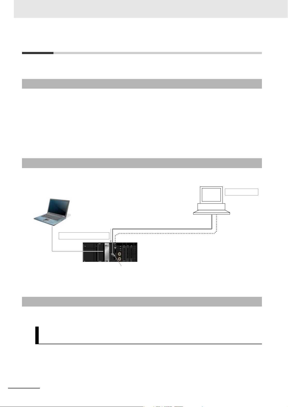
- SCADA software
- MES etc.
Ethernet network
Built-in EtherNet/IP port
OPC UA Server function
NJ/NX-series CPU Unit
Sysmac Studio
OPC UA Client
Securely connects and reads and writes variables.
OPC UA communications
1-1 Overview and Features
This section describes an overview and features of the OPC UA Server function.
1-1-1 Overview
The OPC UA Server function enables the NJ/NX-series CPU Unit to operate as an OPC UA server.
With this function, OPC UA clients can connect via Ethernet to the built-in EtherNet/IP port of the
NJ/NX-series CPU Unit using the OPC UA communications, and then read and write variables in the
CPU Unit.
The OPC UA communications can simultaneously achieve both addressing security risks and connecting with general-purpose methods. Therefore, the OPC UA Server function enables secure data
exchanges between the CPU Unit and host systems such as SCADA or MES compatible OPC UA so
that the host systems can collect manufacturing progress information or issue manufacturing instructions.
1-1-2 System Configuration
The OPC UA Server function supports the following system configuration.
Refer to A-5 Version Information on page A-19 for the Unit version of the CPU Unit and the version of
the Sysmac Studio that can be supported.
1-1-3 Features
The OPC UA Server function has the following features.
Supporting OPC UA Communications as Secure Industrial Standard
Communications
OPC UA communications have the following features.
• A versatile global standard network from discrete control to process control, and from the sensor or
controller level to the host monitoring and management level.
1 - 2
• Also defined as a recommended communications standard of Industrie 4.0 to connect the control networks in factories to the IT networks.
NJ/NX-series CPU Unit OPC UA User’s Manual (W588)
Page 27

1 Overview of OPC UA Server Function
• Allows full-scale secure information exchange in the industrial system consisting of different devices.
• Allows to expand the visualization of information adapting to the system in the object-based Address
Space.
Providing the Server Function of OPC UA Communications in the
NJ/NX-series Controller
1-1 Overview and Features
The NJ/NX-series OPC UA Server function has the following features.
• It allows the Controller to connect directly to the OPC UA client via Ethernet without relaying the computer.
• Since the NJ/NX-series CPU Unit has EtherCAT communications as the lower level network, it
makes it easy to gather sensor and actuator level information on EtherCAT into OPC UA communications as a higher network.
• You can check the operation results of the OPC UA Server function from the event log in the Controller and the Execution Log.
1
1-1-3 Features
NJ/NX-series CPU Unit OPC UA User’s Manual (W588)
1 - 3
Page 28

1 Overview of OPC UA Server Function
1-2 Specifications
This section describes the specifications of the OPC UA Server function.
1-2-1 List of Supported CPU Units
The OPC UA Server is supported by the following CPU Unit models.
CPU Unit Models Unit version
NX701-1600
NX701-1700
NX701-1620
NX701-1720
NJ501-1300
NJ501-1400
NJ501-1500
NX102-9000
NX102-1000
NX102-1100
NX102-1200
NX102-9020
NX102-1020
NX102-1120
NX102-1220
1.24 or later
1.17 or later
1.30 or later
1 - 4
NJ/NX-series CPU Unit OPC UA User’s Manual (W588)
Page 29

1 Overview of OPC UA Server Function
1-2-2 Function Specifications
Specifications of the OPC UA Server
Item NJ501-100 NX701-1 NX102-
Built-in EtherNet/IP
port on the CPU
Connection ports
OPC UA function Server function
Transport and data encoding UA TCP binary
Supported profile and model
Endpoint URL (Server URL)
Maximum number of sessions (client) 5
Maximum number of monitored items per server 2,000
Maximum number of subscriptions per server 100
Variable type Network variable
Conditions as
a whole network-published
variables
Conditions that can not be published for each net-
work-published variable
OPC UA security mode and policy
Application
authentication
Maximum number of variables that
can be published
Maximum number of value attributes that can be published
Maximum number of structure defi-
*1
nitions that can be published
*1
Authentication X.509
Number of certificates that can be
stored
Unit
Note: The OPC UA Server can be used simultaneously with Eth-
erNet/IP communications.
Micro Embedded Device Server Profile
PLCopen Information Model
opc.tcp: // [IP address] : [port number] /
By default, below.
opc.tcp: //192.168.250.1: 4840 /
10,000
10,000
100
• Multidimensional array specified structure
• Structure containing multidimensional array(s) as member(s)
• Structure whose nesting number exceeds three
• Union, and structure containing union(s) as member(s)
• Array whose start number is not 0; e.g., Array[2..5]
• Array whose number of elements exceeds 1024
• Structure whose number of members exceeds 100
• Variable whose size exceeds 1024 bytes
Allowable security methods can be specified from the following
(multiple specifications possible):
• Both signature and encryption required: SignAndEncrypt
Signature and encryption algorithm: Basic256Sha256/Basic256/Basic128Rsa15
(multiple specifications possible)
• Only signature required: Sign
Signature algorithm: Basic256Sha256/Basic256/Basic128Rsa15 (multiple specifications possible)
• Neither signature nor encryption required
• Trusted certificate: 32
• CA certificate: 32
• Rejected certificate: 32
Built-in EtherNet/IP port (PORT 1) on the
CPU Unit
1-2 Specifications
1
1-2-2 Function Specifications
NJ/NX-series CPU Unit OPC UA User’s Manual (W588)
1 - 5
Page 30

1 Overview of OPC UA Server Function
Precautions for Correct Use
Item NJ501-100 NX701-1 NX102-
User authentication
*1. For details, refer to Restrictions on Publishing to the OPC UA Client on page 6-8.
Method of user authentication
For the NX701-1 CPU Unit and NX102- CPU Unit, there are two built-in
EtherNet/IP ports, PORT 1 and PORT 2. Note that only PORT 1 is the port that supports the
OPC UA Server.
The following can be set:
• User name and Password
• Anonymous
1 - 6
NJ/NX-series CPU Unit OPC UA User’s Manual (W588)
Page 31

1 Overview of OPC UA Server Function
1-3 OPC UA Server Procedures
This section describes the OPC UA Server Procedures.
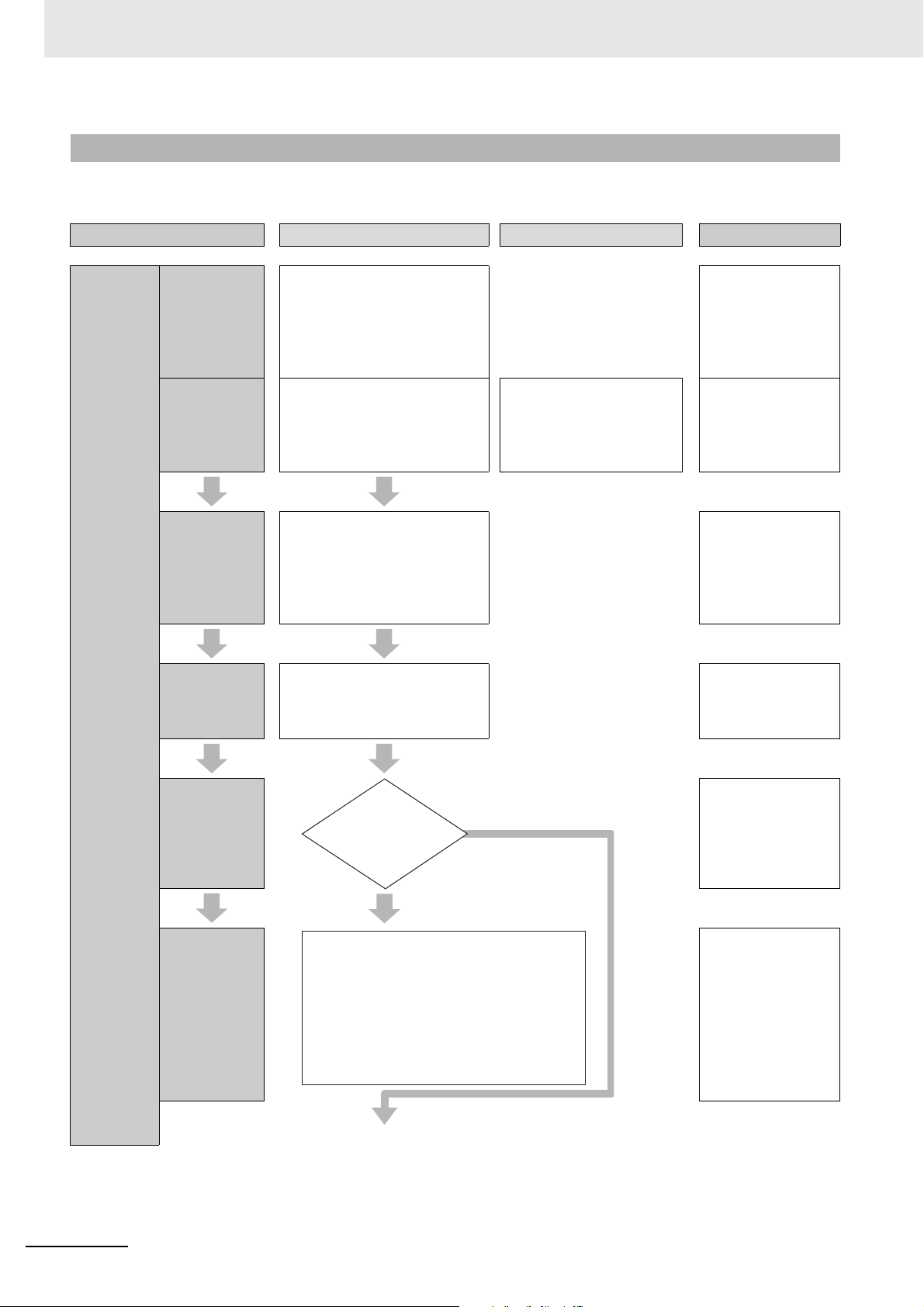
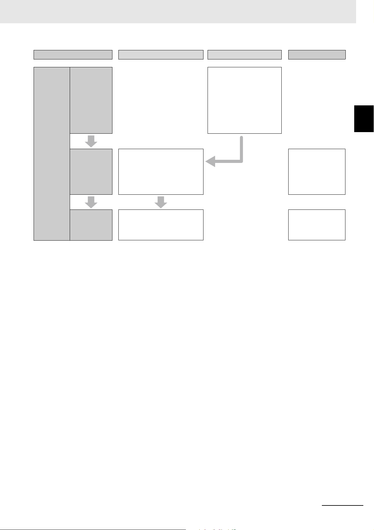
1-3-1 Overall Procedure
The overall procedure for using the OPC UA Server is as follows. For details, refer to 1-3-2 Procedure
Step Description Reference
STEP1. Settings
Details on page 1-8.
1-1. IP address setting of the
built-in EtherNet/IP port
1-2. OPC UA Settings (offline)
1-3. Settings for publishing
variables to the OPC UA client
1-4. Downloading
(synchronization)
(When using for the first time)
1-5. Cycling the power supply to
the Controller or resetting the
Controller
1-6. Confirm the start of OPC UA
Server (online)
1-7. OPC UA Settings (online)
Section 3 Settings of
the OPC UA Server
• Offline: Whether OPC UA server
is used or not
• Public settings of global variables
• Online: server certificate, client
certificates, security settings
1-3 OPC UA Server Procedures
1
1-3-1 Overall Procedure
STEP2. Operation
STEP3. Shut-down
STEP4. Trouble
shooting
2-1. Connectiing from an OPC UA
client
2-2. Checking communications
from the OPC UA client
2-3. Reading and writing variables
from the OPC UA client
3-1. Stopping the Controller
4-1. Client error check
4-2. Status Monitor
4-3. Checking the event log
• Referencing the server address
space from the OPC UA client
• Designing the variable designation
• Disconnecting from the client.
• Shutting down the OPC UA
Server.
• Turning OFF the power supply
to the Controller.
• Checking the operating status of
the OPC UA server function, etc.
• Checking the status log
Section 6 Connecting
from the OPC UA
Client and
Reading/Writing
Variables
4-2-1 Checking Based
on OPC UA Server
Status of the Sysmac
Studio on page 4-5
4-2-1 Checking Based
on OPC UA Server
Status of the Sysmac
Studio on page 4-5
Section 9
Troubleshooting
NJ/NX-series CPU Unit OPC UA User’s Manual (W588)
1 - 7
Page 32
1 Overview of OPC UA Server Function
In step
1-2, the OPC
UA server was
changed from Do
not use (default)
to Use.
Cycling the power supply to the Controller
or select Reset Controller from the Con-
troller Menu in the Sysmac Studio.
Note: If you change the OPC UA server
from Do not use to Use in step 1-2, the
OPC UA Server will not be started unless
this operation is performed.
Yes
(Used for the first time, etc.)
No
(Keep Use)
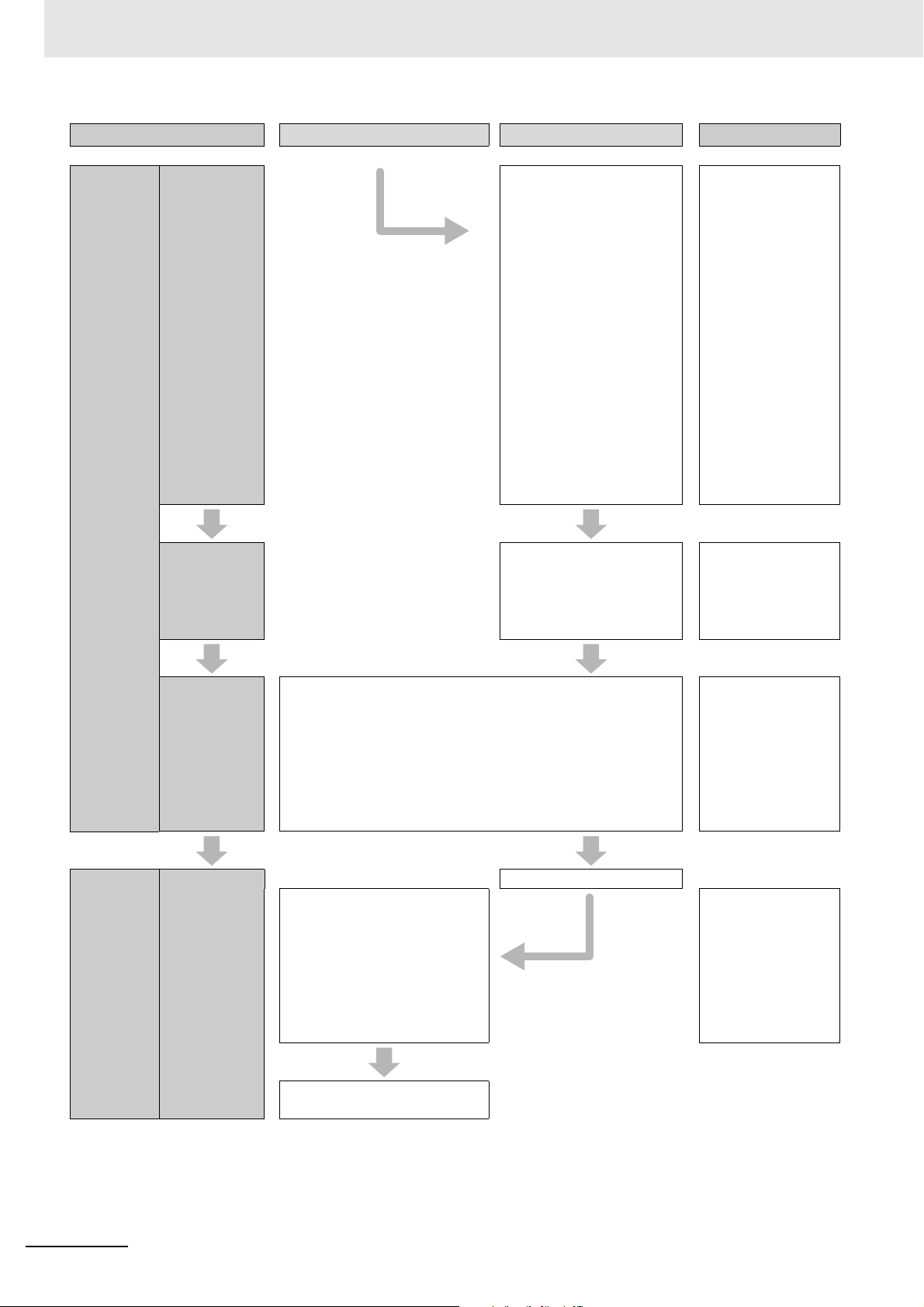
1-3-2 Procedure Details
The procedure for using the OPC UA Server is shown separately for the OPC UA Server side and
the OPC UA client side as follows.
Step OPC UA Server
OPC UA client
*1
Reference
STEP1.
Settings
1-1. IP
address setting of the
built-in EtherNet/IP port
1-2. OPC UA
Settings
(offline)
1-3. Settings
for publishing
variables to
the OPC UA
client
1-4.
Downloading
(synchronizati
on)
Set the IP address of the built-in
EtherNet/IP port in Configura-
tions and Setup - Controller
Setup - Built-in EtherNet/IP
Port Settings in the Multiview
Explorer in the Sysmac Studio.
Make the settings from Config-
urations and Setup - OPC UA
Server Settings. (Select OPC
UA Server to Use and set the
port number)
In the the Global Variable Editor
of the Sysmac Studio, register
the global variables for OPC UA
communications with Network
Publish Attribute set to Publish
Only, Input, or Output.
Download the OPC UA Settings
and global variables from the
Sysmac Studio to the CPU Unit
(using synchronize function)
• Create client certificates
• Other settings of OPC
UA client side
3-1-1 IP Address
Settings of the
Built-in EtherNet/IP
Port on page 3-2
3-2-2 OPC UA
Server Settings on
page 3-7
3-3 Creating Variables for OPC UA
Communications on
page 3-27
Sysmac Studio Version1 Operation
Manual (Cat.
No.W504)
Conditional
branching by
OPC UA
Server Use
Option
(When using
for the first
time)
1-5. Cycling
the power supply to the Controller or
resetting the
Controller
3-2-2 OPC UA
Server Settings on
page 3-7
3-2-3 When necessary to cycle the
power supply to the
Controller or reset
the Controller on
page 3-10
4-1 Starting or Stopping the OPC UA
Server on page 4-2
1 - 8
NJ/NX-series CPU Unit OPC UA User’s Manual (W588)
Page 33

1 Overview of OPC UA Server Function
1-3 OPC UA Server Procedures
STEP1.
Settings
Step OPC UA Server
1-6. Confirm-
ing the start of
OPC UA
Server (online)
1-7. OPC UA
Settings
(online)
Confirm that the OPC UA
Server is started.
In the Sysmac Studio, connect
online to the CPU Unit, and
then right-click OPC UA Server
Settings and select Server
Status.
Use the following procedure
from Configurations and
Setup – OPC UA Server Settings in the Sysmac Studio.
Server certificate operations:
Right-click OPC UA Server
Settings and select Server
Certificate.
Click the Regenerate certificate Button to set the details of
the server certificate and perform the regenerate operation
of the server certificate
*2*3
OPC UA client
*1
Reference
4-2-1 Checking
Based on OPC UA
Server Status of the
Sysmac Studio on
page 4-5
1
1-3-2 Procedure Details
Section 5 Security
Function of OPC UA
Server
Regenerating the
Server Certificate on
page 3-13
.
Export the server certificate. Import the server certifi-
cate on the OPC UA client
side
Client certificates operations:
Right-click OPC UA Server
Settings and select Client
Authentication.
• Operations such as adding
the client certificates created
on the client sides in step 1-2.
Security Settings operations:
Right-click OPC UA Server
Settings and select Security
Settings.
• User Authentication Settings
• Anonymous login
• Security Policy
Note:In order to support the
CA-signed client certificates,
the CA certificate and certificate
revocation list must be registered.
Exporting Server
Certificate on page
3-13
Client Authentication on page 3-15
3-2-6 Security Settings on page 3-22
A-3 When
CA-signed Client
Certificates Supported on page A-13
NJ/NX-series CPU Unit OPC UA User’s Manual (W588)
1 - 9
Page 34
1 Overview of OPC UA Server Function
STEP2.
Operation
Step OPC UA Server
2-1. Connect-
ing from an
OPC UA client
2-2. Checking
communications from the
OPC UA Client
OPC UA client
Connection to the OPC UA
Server.
Enter opc.tcp: // [IP
address] : [port number] /
as the URL.
Note:By default on the NJ
side, opc.tcp:
//192.168.250.1: 4840 /
Enter the IP address set in
step 1-1 and the port number set in step 1-2 here.
• Specify the OPC UA
security mode and policy.
• Enter user name and
password (when user
authentication is
required) .
• Refer the server address
space from the OPC UA
client
• Design the variable designation
*1
Reference
6-1 Connecting from
the OPC UA Client
on page 6-2
6-2 Reading/Writing
Variables from the
OPC UA Client on
page 6-3
STEP3.
Shut-down
2-3. Reading
and writing
variables from
the OPC UA
client
3-1. Stopping
the Controller
Read/write variables in the CPU Unit from the OPC UA client
via the OPC UA Server.
Confirm variables in the CPU Unit with a monitor such as a
Watch Tab Page on the Sysmac Studio.
Disconnection
Shut down the OPC UA Server. 4-1-1 How to Start or
Turn OFF the power supply to
the Controller.
6-2-2 Reading/Writing the Variables of
the CPU Unit on
page 6-5
Sysmac Studio Version1 Operation
Manual (Cat.
No.W504)
Stop the OPC UA
Server on page 4-2
4-2-1 Checking
Based on OPC UA
Server Status of the
Sysmac Studio on
page 4-5
1 - 10
NJ/NX-series CPU Unit OPC UA User’s Manual (W588)
Page 35
1 Overview of OPC UA Server Function
1-3 OPC UA Server Procedures
STEP4.
Trouble
shooting
Step OPC UA Server
4-1. Client
error check
4-2. Status
Monitor
4-3. Confirming the event
log
Monitor status such as the
operating status of the OPC UA
Server and the number of connected clients in the Server Status Tab Page of the Sysmac
Studio.
Check errors saved as Controller Events using troubleshooting functions of the Sysmac
Studio.
OPC UA client
Confirm the error on the
OPC UA client side
• Check network settings
• Confirm the URL
• Confirm the security pol-
icy
• Confirm the server certifi-
cate, etc.
*1
Reference
1
1-3-2 Procedure Details
4-2-1 Checking
Based on OPC UA
Server Status of the
Sysmac Studio on
page 4-5
Section 9
Troubleshooting
*1. For operation of the OPC UA client, refer to the manual of each OPC UA client.
*2. The server certificate is generated with the IP address that is set.
After that, when you change the IP address by setting operation or instruction execution, be sure to regenerate the
server certificate. If the server certificate is not regenerated, the IP address of the built-in EtherNet/IP port will not match
the IP address of the server certificate. In that case, note that the OPC UA client can not connect to the OPC UA Server.
*3. If the OPC UA Server remains Use before and after the downloading (synchronization function) in step 1-4, this opera-
tion of regenerating the server certificate is not necessary.
NJ/NX-series CPU Unit OPC UA User’s Manual (W588)
1 - 11
Page 36

1 Overview of OPC UA Server Function
1 - 12
NJ/NX-series CPU Unit OPC UA User’s Manual (W588)
Page 37

Structure of the OPC UA Server
This section describes the structure of the OPC UA Server.
2-1 Internal Structure of the Overall OPC UA Communications System . . . . 2-2
2-1-1 Overview . . . . . . . . . . . . . . . . . . . . . . . . . . . . . . . . . . . . . . . . . . . . . . . . . . . . . 2-2
2-1-2 Details . . . . . . . . . . . . . . . . . . . . . . . . . . . . . . . . . . . . . . . . . . . . . . . . . . . . . . . 2-3
2-2 Overview of the Security Function of the OPC UA
Server . . . . . . . . . . . . . . . . . . . . . . . . . . . . . . . . . . . . . . . . . . . . . . . . . . . . . . . 2-5
2
NJ/NX-series CPU Unit OPC UA User’s Manual (W588)
2 - 1
Page 38
2 Structure of the OPC UA Server
Sysmac Studio
Reading
and
writing
OPC UA Server
Variables
(Connection, reading/writing of
variables, etc.) Connect
via built-in EtherNet/IP port
Setting (Offline and Online)
OPC UA communications
OPC UA server side (CPU Unit)
OPC UA client side
Settings for communications
with clients
2-1 Internal Structure of the Overall OPC
UA Communications System
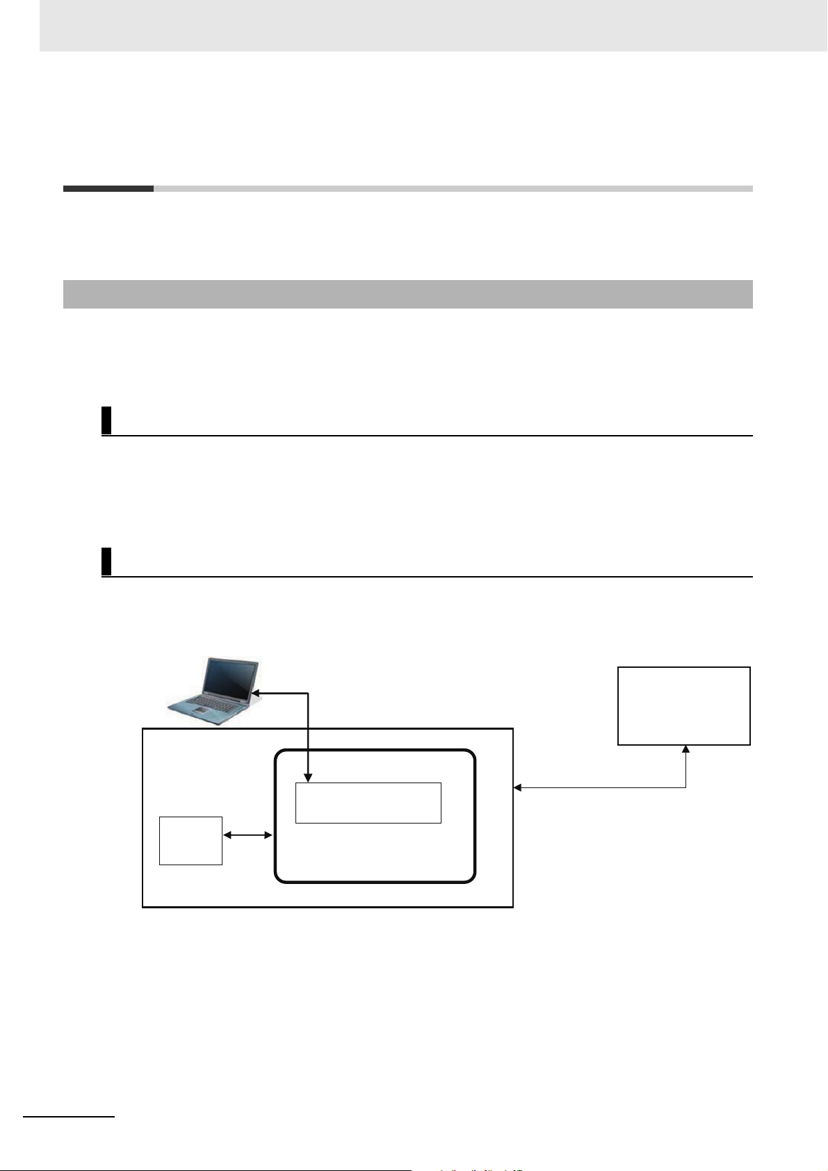
This section describes the internal structure of the overall OPC UA communications system with the
NJ/NX-series CPU Units as an OPC UA server.
2-1-1 Overview
An overview of the overall OPC UA communications system is provided below.
The description is given separately for the NJ/NX-series CPU Unit side as a server and the OPC UA client side.
OPC UA Server Side (CPU Unit Side)
• Set in advance the parameters for communications with the OPC UA client to the CPU Unit from the
Sysmac Studio. There are settings that can be done offline and ones that are only available online.
• Start a communications service that is called OPC UA Server and execute the OPC UA communications.
OPC UA Client Side
• Connect from the OPC UA client to the CPU Unit as a server.
• Read and write variables in the CPU Unit as a server from the OPC UA client.
2 - 2
NJ/NX-series CPU Unit OPC UA User’s Manual (W588)
Page 39
2 Structure of the OPC UA Server
OPC UA Server Settings (a)
Sysmac Studio
Log files
SD Memory Card (sold separately)
Trusted Certificate List
Reading
and
writing
Server
certificate
Client
certificate
OPC UA Server
Trusted Certificate List
Event Log (d)
Execution Log (e)
Server
certificate
(Can be read from the
Sysmac Studio)
Additional
registration
Service
request
Refer to server
address space
Design variables
specifications
Global variable (b)
Use of OPC UA server etc.
· Set OPC UA Settings offline and online
(Can be read from
the Sysmac Studio)
(Published to OPC UA
client)
OPC UA server side (CPU Unit)
OPC UA client side
Client Authentication
· Create global variables offline
Application authentication (c)
Rejected Certificate List
(Connection, reading/writing of variables, etc.)
Connect via built-in EtherNet/IP port
OPC UA communications
Client
certificate
Client
certificate
*1
2-1 Internal Structure of the Overall OPC UA
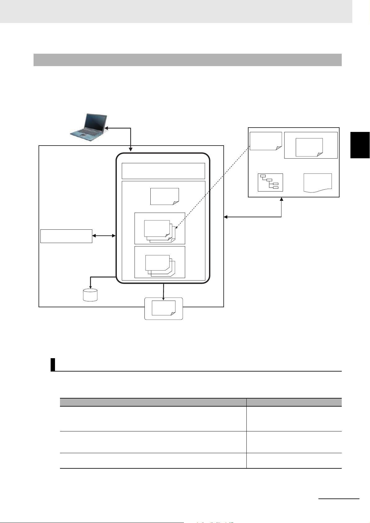
2-1-2 Details
The details of the structure of the overall OPC UA communications system is described by using the following figure.
Note that the (Figure a) to (Figure e) in the table shown below correspond to the (a) to (e) in the following figure.
Communications System
2
2-1-2 Details
NJ/NX-series CPU Unit OPC UA User’s Manual (W588)
Note 1. The above figure shows the case of a self-signed client certificate. You can also support a CA-signed cli-
ent certificate. To use the CA-signed client certificate, refer to A-3 When CA-signed Client Certificates
Supported on page A-13.
Basic Mechanism
The basic mechanism from the start for using the OPC UA Server to reading and writing variables is as
follows. The basic mechanism is shown in accordance with the usage procedure.
Basic mechanism (the number indicates the order of procedure) Reference
1. In the Sysmac Studio, set OPC UA Server Settings from Configurations and Setup - OPC UA Settings in Multiview Explorer by an
offline operation. (Figure a).
2. Create global variables to be published for OPC UA communications
(with the network publish attribute set to Public Only, Input, or Output)
3-1 Controller Setup on page 3-2
3-2-2 OPC UA Server Settings on
page 3-7
3-3 Creating Variables for OPC UA
Communications on page 3-27
(Figure b).
3. Transfer OPC UA server settings and global variables to the CPU
Unit using synchronization function from the Sysmac Studio.
Sysmac Studio Version1 Operation
Manual (Cat. No.W504)
2 - 3
Page 40

2 Structure of the OPC UA Server
Basic mechanism (the number indicates the order of procedure) Reference
4. In the Sysmac Studio, connect online to the CPU Unit, and perform
operations of the application authentications and security settings
(Figure c).
5. Turn ON the power supply to the Controller and start using the OPC
UA Server.
Note: The OPC UA server in OPC UA Server Settings must be set
to Use.
6. Connect from the OPC UA client to the OPC UA Server.
• Connect to the server by specifying opc.tcp: // [IP address] : [port
No.] / as the URL.
• Enter the User name and Password from the OPC UA client.
7. Reading and writing from the OPC UA client
• From the OPC UA client, refer to the address space of the OPC UA
Server and design variables specifications.
• Request service from the OPC UA client, read and write global vari-
ables of the CPU Unit published to OPC UA communications.
Sysmac Studio Version1 Operation
Manual (Cat. No.W504)
3-2-5 Setting and Displaying the
Certificate on page 3-11
3-2-6 Security Settings on page 3-22
4-1 Starting or Stopping the OPC UA
Server on page 4-2
6-1 Connecting from the OPC UA
Client on page 6-2
6-2 Reading/Writing Variables from
the OPC UA Client on page 6-3
Status Confirmation
The following table shows how to confirm the status of the OPC UA Server.
Means of con-
firmation
OPC UA server
status
Event Log Failure of OPC UA Server and status are stored as event logs
Execution Log Logs (Figure e) for recording the execution status of the OPC UA
The server operating status and the number of currently connected OPC UA clients can be checked with the OPC UA server
status in the Sysmac Studio.
(Figure d) of the NJ/NX-series Controllers.
You can confirm with troubleshooting functions of the Sysmac Studio.
Server, variable published-status, authentication processing, and
operation of certificates are saved as a log file in the SD Memory
Card (sold separately) in the CPU Unit.
You can confirm in Operation Logs Display on the Sysmac Studio.
Status confirmation mechanism Reference
4-2 Checking the Status
of the OPC UA Server on
page 4-5
Section 9 Troubleshooting
Section 7 Execution Log
Functions
2 - 4
NJ/NX-series CPU Unit OPC UA User’s Manual (W588)
Page 41

2 Structure of the OPC UA Server
2-2 Overview of the Security Function of
the OPC UA Server
This section describes the overview of the security function of the OPC UA Server.
The OPC UA Server of the NJ/NX-series CPU Unit supports the server function of the OPC UA. There
are the following two security functions as a server in the OPC UA Server.
Function Description
Connection authentication function
of the OPC UA Server
Message security function Upon receiving requests from OPC UA clients and sending responses to
When a connection request is accepted from an OPC UA client and its
users, the OPC UA Server permits connections from only authenticated
OPC UA clients and users.
OPC UA clients, the OPC UA Server signs and encrypts the messages.
2-2 Overview of the Security Function of the
OPC UA Server
2
Function Setting Reference
Connection
authentication
function of the
OPC UA Server
Message security function
Certificate settings
User Authentication Settings
OPC UA security mode and policy that are allowed for the OPC UA client as a server
• Regeneration of the server certificate (only when
necessary)
• Self-signed client certificates:
Additional registration of client certificates, and
trust or reject settings of each client certificate at
client authentication
• CA-signed client certificates:
Additional registration of CA certificates and certificate revocation list at client authentication and
issuer authentication
• User name and Password to authenticate
• Prohibition or permission for anonymous login
3-2-5 Setting and Displaying the Certificate on page 3-11
A-3 When CA-signed
Client Certificates
Supported on page
A-13
3-2-6 Security Settings on page 3-22
3-2-6 Security Settings on page 3-22
For details on the security functions, refer to Section 5 Security Function of OPC UA Server.
Set the following contents, in advance, to use the security functions as a server.
NJ/NX-series CPU Unit OPC UA User’s Manual (W588)
2 - 5
Page 42

2 Structure of the OPC UA Server
2 - 6
NJ/NX-series CPU Unit OPC UA User’s Manual (W588)
Page 43

Settings of the OPC UA Server
This section describes the settings required to use the OPC UA Server.
3-1 Controller Setup . . . . . . . . . . . . . . . . . . . . . . . . . . . . . . . . . . . . . . . . . . . . . . . 3-2
3-1-1 IP Address Settings of the Built-in EtherNet/IP Port . . . . . . . . . . . . . . . . . . . . 3-2
3-2 OPC UA Settings . . . . . . . . . . . . . . . . . . . . . . . . . . . . . . . . . . . . . . . . . . . . . . 3-3
3-2-1 Overview of OPC UA Settings . . . . . . . . . . . . . . . . . . . . . . . . . . . . . . . . . . . . 3-3
3-2-2 OPC UA Server Settings . . . . . . . . . . . . . . . . . . . . . . . . . . . . . . . . . . . . . . . . 3-7
3-2-3 When necessary to cycle the power supply to the Controller or reset
the Controller . . . . . . . . . . . . . . . . . . . . . . . . . . . . . . . . . . . . . . . . . . . . . . . . 3-10
3-2-4 Automatic Generation of the Server Certificate . . . . . . . . . . . . . . . . . . . . . . 3-10
3-2-5 Setting and Displaying the Certificate . . . . . . . . . . . . . . . . . . . . . . . . . . . . . . .3-11
3-2-6 Security Settings . . . . . . . . . . . . . . . . . . . . . . . . . . . . . . . . . . . . . . . . . . . . . . 3-22
3-2-7 Server Status . . . . . . . . . . . . . . . . . . . . . . . . . . . . . . . . . . . . . . . . . . . . . . . . 3-25
3-2-8 Displaying the Operation Logs . . . . . . . . . . . . . . . . . . . . . . . . . . . . . . . . . . . 3-25
3-2-9 Operations for the OPC UA Settings . . . . . . . . . . . . . . . . . . . . . . . . . . . . . . 3-26
3-3 Creating Variables for OPC UA Communications . . . . . . . . . . . . . . . . . . . 3-27
3-3-1 Global Variables Published to OPC UA Communications . . . . . . . . . . . . . . 3-27
3-3-2 Adding or Deleting Network-published Variables . . . . . . . . . . . . . . . . . . . . . 3-28
3
NJ/NX-series CPU Unit OPC UA User’s Manual (W588)
3 - 1
Page 44

3 Settings of the OPC UA Server
Precautions for Correct Use
3-1 Controller Setup
This section describes the following Controller Setup related to the OPC UA function.
• Setting the IP address of the built-in EtherNet/IP port
• Setting the Start delay time at startup when you want to shorten the startup time of the OPC UA
Server
For general settings of the built-in EtherNet/IP port, refer to the NJ/NX-series CPU Unit Built-in Ether-
Net/IP Port User’s Manual (Cat. No. W506).
For details on the operation, refer to the Sysmac Studio Version 1 Operation Manual (Cat. No. W504).
3-1-1 IP Address Settings of the Built-in EtherNet/IP Port
Select one of the following settings in the IP address of TCP/IP Settings in Configurations and
Setup - Controller Setup - Built-in EtherNet/IP Port Settings in the Multiview Explorer in the Sysmac
Studio:
Fixed Setting, or Fix at the IP address obtained from BOOTP server
For details on the settings, refer to the NJ/NX-series CPU Unit Built-in EtherNet/IP Port User’s Manual
(Cat. No. W506)
The server certificate is automatically or manually generated with the IP address that is set in the Controller Setup. For information on automatic generation of server certificates, refer to 3-2-4 Automatic
Generation of the Server Certificate on page 3-10. For information on the manual regeneration of
server certificates, refer to the Regenerating the Server Certificate in 3-2-5 Setting and Displaying the
Certificate on page 3-11.
If you change the IP address by downloading the settings or executing the instruction after the
server certificate is generated automatically or manually, the IP address of the built-in EtherNet/IP port will not match that of the Server certificate. As a result, the OPC UA client can not
connect to the OPC UA Server. Then, a Server Certificate Mismatch event (event code:
15020000 hex) occurs. In that case, manually regenerate the server certificate or set the IP
address back to the original address.
3 - 2
NJ/NX-series CPU Unit OPC UA User’s Manual (W588)
Page 45

3-2 OPC UA Settings
OPC UA Settings
You must set the OPC UA Settings before the OPC UA Server runs.
This section describes how to set the OPC UA Settings.
3-2-1 Overview of OPC UA Settings
The following is an overview of the OPC UA Settings.
The OPC UA Settings are located in Configurations and Setup in Multiview Explorer in the Sysmac
Studio as follows.
3 Settings of the OPC UA Server
3-2 OPC UA Settings
3
3-2-1 Overview of OPC UA Settings
There are three types of OPC UA Settings; items that are recorded in the project file in the Sysmac
Studio, items that are not recorded in the project file in the Sysmac Studio and required to be set for
each CPU Unit , and items that are only displayed or operated without any setting. The differences of
each are described in the table below.
Item Description Backup
Items that are recorded in the
project file
Items that are not recorded in
the project file and required to
be set for each CPU Unit
Items that are only displayed
or operated
The settings are recorded in the project file in the
Sysmac Studio.
Download the project file to the CPU Unit after setting on
the Sysmac Studio.
The settings are not recorded in the project file in the
Sysmac Studio.
You must make the settings online for each CPU Unit.
There is no setting to make, the data in the CPU Unit is
only displayed or operated.
Applicable
Applicable
Not applicable
NJ/NX-series CPU Unit OPC UA User’s Manual (W588)
3 - 3
Page 46

3 Settings of the OPC UA Server
Items That Are Recorded in the Project File
Items of OPC UA
Settings
OPC UA Server
Settings
Set the following items in the OPC UA
Server Settings Tab Page.
• Use of the OPC UA Server: Set
whether to use.
• End Point Settings:
Contents Procedure Reference
Double-click OPC UA
Server Settings or
3-2-2 OPC UA Server Settings on page 3-7
right-click it and
select Edit from
menu
Display the End point and set
the port number.
• Execution Log Settings:
Set whether to record, set the
number of log files, and set the
number of records.
Items That Are Not Recorded in the Project File
The following table gives the items that are not recorded in the project file and required to be set for
each CPU Unit.
For some of these items, there are restrictions on the operation authority from the Sysmac Studio. For
details on the operation authority of the OPC UA Server in the Sysmac Studio, refer to 8-1 The Sysmac
Studio Operation Authority Verification Related to the OPC UA Server on page 8-2.
The following table gives the the items that are recorded in the project file.
3 - 4
NJ/NX-series CPU Unit OPC UA User’s Manual (W588)
Page 47

3 Settings of the OPC UA Server
Items of OPC UA
Settings
Server Certificate Display and operate the server certifi-
cate in the Server Certificate Tab
Page.
Client Authentication
• For a self-signed client certificate:
Display and operate the Trusted
Certificate List and the Client
Rejected Certificate List in the Client
Authentication Tab Page.
• For a CA-signed client certificate:
Display and operate the Trusted
Certificate List of the CA certificate
that is signed and the Certificate
Revocation List in the Client Authen-
tication Tab Page.
Issuer authentication
• For a CA-signed client certificate
only:
Display and operate the Trust List of
the CA’s own Certificate and the
Certificate Revocation List in the
Issuer Authentication Tab Page.
Security Settings The following settings are made in the
Security Setting Tab Page.
• User name and Password to authenticate
• Prohibition or permission for anonymous login
• Security mode policy
Contents Procedure Reference
Right-click OPC UA
Server Settings and
select from the menu.
3-2-3 When necessary to
cycle the power supply to
the Controller or reset the
Controller on page 3-10
Client Authentication on
page A-14
Issuer Authentication on
page A-16
3-2-6 Security Settings on
page 3-22
3-2 OPC UA Settings
3
3-2-1 Overview of OPC UA Settings
NJ/NX-series CPU Unit OPC UA User’s Manual (W588)
3 - 5
Page 48

3 Settings of the OPC UA Server
Items That Are Only Displayed or Operated
The following table gives the items that are only displayed or operated.
Items of OPC UA
Settings
Server Status Display the operating status of the
OPC UA Server and shutdown the
OPC UA Server in the Server Status
Tab Page.
Operation Log Display
List and operate the Execution Logs in
the Show Operation Log Tab Page.
Contents Procedure Reference
Right-click OPC UA
Server Settings and
select from the menu.
4-2-1 Checking Based on
OPC UA Server Status of
the Sysmac Studio on
page 4-5
Right-click OPC UA
Settings and select
7-2 Checking the Execution Log on page 7-13
from the menu.
3 - 6
NJ/NX-series CPU Unit OPC UA User’s Manual (W588)
Page 49
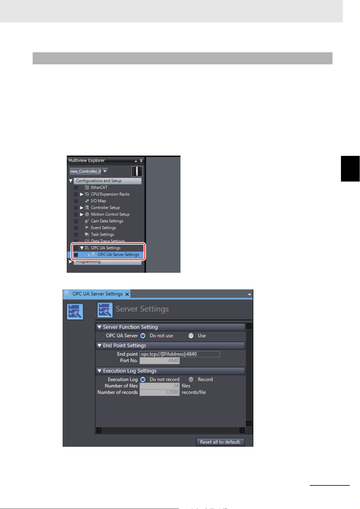
3-2-2 OPC UA Server Settings
The following shows how to make the OPC UA Server Settings and its contents.
The OPC UA Server Settings consist of the following.
• OPC UA Server Use Option setting
• End point Settings
• Execution Log Settings
1 Double-click OPC UA Server Settings under Configurations and Setup - OPC UA Settings
in Multiview Explore in the Sysmac Studio. Alternatively, right-click OPC UA Server Settings
and select Edit from the menu.
3 Settings of the OPC UA Server
3-2 OPC UA Settings
3
3-2-2 OPC UA Server Settings
The following OPC UA Server Settings Tab Page is displayed.
NJ/NX-series CPU Unit OPC UA User’s Manual (W588)
3 - 7
Page 50

3 Settings of the OPC UA Server
Use of the OPC UA Server
You can set whether to use the OPC UA Server in Server Function Setting,
Parameter
Server Settings
Setting
group
Server
Function
Setting
Description Set value Default
Set whether to use the
OPC UA Server
• Do not use
•Use
Do not use When
Update
Timing
downloaded to
CPU Unit
Changes in
RUN mode
Not allowed
After you download the project whose OPC UA Server in the OPC UA Settings was changed from Do
not use to Use to the CPU Unit, and then cycle the power supply to the Controller or reset the Controller, the OPC UA Server will start automatically at that time.
For details on how to start the OPC UA, refer to 4-1 Starting or Stopping the OPC UA Server on page
4-2.
End Point Settings
In the End Point Settings, display the end point and set the port number.
Set the following items.
Set and display the following items.
Parameter
End Point
Settings
*1. It can be set only when OPC UA server is set to Use.
Setting
group
End point The End point notation of the
Port No. Set the port number to be
Description
OPC UA Server is displayed.
• The [IPAddress] section on
the right column shows the
IP address of the built-in
EtherNet/IP port in the
NJ/NX-series CPU Unit.
• The [Port] section on the
right column automatically
shows the value of the set
Port No. shown below.
used for the OPC UA
*1
Server
.
Set value or
display value
opc.tcp: //
[IPAddress] :
[Port]
Note. Not
allowed
to set.
Display
only.
1025 to 65535 4840 When
Default
opc.tcp://192.
168.250.1:48
40
Update
Timing
--- ---
downloaded to
CPU Unit
Changes
in RUN
mode
Not
allowed.
3 - 8
NJ/NX-series CPU Unit OPC UA User’s Manual (W588)
Page 51

3 Settings of the OPC UA Server
Precautions for Correct Use
• The IP Address Displayed at the End point
The IP address that is displayed at the
For details on how to set the IP address from the Sysmac Studio, refer to the NJ/NX-series
CPU Unit Built-in EtherNet/IP Port User’s Manual (Cat. No. W506).
The IP address of the built-in EtherNet/IP port can also be changed with the ChangeIPAdr
(Change IP Address) instruction.
However, if you change the IP address by downloading the settings or executing the instruction after server certificate is generated automatically or manually, the IP address of the
built-in EtherNet/IP port will not match that of the server certificate. As a result, the OPC UA
client can not connect to the OPC UA Server. Then, a Server Certificate Mismatch event
(event code: 15020000 hex) occurs. In that case, manually regenerate the server certificate
or set the IP address back to the original address.
• Duplication of Used Port Number with Other Communications Services
Make sure that the port number set in End point - Port No. does not use the same port number used for other communications service (such as FTP server, HTTP server, CIP message,
FINS/TCP, and system). For the port number used for the built-in EtherNet/IP port, refer to
the NJ/NX-series CPU Unit Built-in EtherNet/IP Port User’s Manual (Cat. No. W506).
End point
is the IP address of the built-in EtherNet/IP port.
3-2 OPC UA Settings
3
3-2-2 OPC UA Server Settings
Execution Log Settings
Specify whether or not to record Execution Logs, and set each specification related to the logs in the
Execution Log Settings.
Set the following items.
Parame-
ter
Execution
Log Settings
*1. It can be set only when OPC UA server is set to Use and Execution Log is set to Record.
Setting group Description Set value Default
Execution Log Sets whether to record Execution Logs. Do not record
Record
Number of files Sets the maximum number of files of the
Execution Logs.
When the maximum number of files is
reached, the oldest file is deleted and a
*1
.
*1
Number of
records
Reset all to
default Button
new file is created
Sets the number of log records that can be
contained in each Execution Log file
Returns all parameters to the default settings.
2 to 100 24
100 to 65,536 12,000
.
--- ---
For details on the Execution Log, refer to Section 7 Execution Log Functions.
Do not record
NJ/NX-series CPU Unit OPC UA User’s Manual (W588)
3 - 9
Page 52
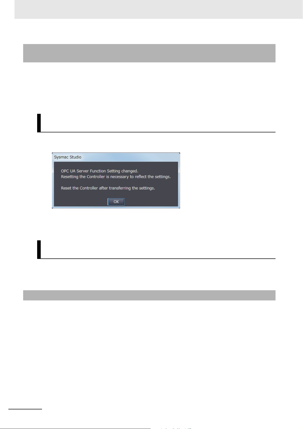
3 Settings of the OPC UA Server
3-2-3 When necessary to cycle the power supply to the Controller or
reset the Controller
You need to cycle the power supply to the Controller or reset the Controller in the following cases:
• Changing OPC UA Server Use Option
the setting to the CPU Unit, and to enable the changes
*1. That means either case of Do not use to Use or Use to Do not use.
• When the Clear All Memory is executed with Use that is set in OPC UA Server Use Option
*1
under OPC UA Settings before downloading or restoring
When data is downloaded or restored after OPC UA Server Use
Option is changed
If the OPC UA Server Use Option is changed, the following dialog box is displayed after the data is
downloaded or restored.
1 Click the OK Button.
2 Then, cycle the power supply to the Controller or reset the Controller.
After the execution of Clear All Memory while the OPC UA Server
Use Option set to Use
When Clear All Memory is executed with the OPC UA Server Use Option set to Use, a similar dialog
box is displayed. For details on how to perform Clear All Memory operation, refer to 8-3 Clear All Mem-
ory Function Related to the OPC UA Server on page 8-9.
3-2-4 Automatic Generation of the Server Certificate
The server certificate is automatically generated in the following case:
• When you cycle the power supply to the Controller or reset the Controller after downloading the project whose OPC UA Server in the OPC UA Settings was changed from Do not use to Use to the CPU
Unit
And
• When there is no server certificate in the CPU Unit
The value of the IP address of the automatically generated server certificate is generated from the IP
address of the built-in EtherNet/IP port at the time.
If you change the IP address after the server certificate is generated automatically or manually, be sure to
regenerate the server certificate manually. For details on how to operate, refer to Regenerating the Server
Certificate in Server Certificate in 3-2-5 Setting and Displaying the Certificate. If the IP address of the server
certificate does not match the IP address of the built-in EtherNet/IP port, OPC UA clients can not connect to
the OPC UA Server.
3 - 10
NJ/NX-series CPU Unit OPC UA User’s Manual (W588)
Page 53

3-2-5 Setting and Displaying the Certificate
(A) Basic information
(B) Details
(C) Operation Button
The following shows how to set and display the certificate and their contents.
The certificate setting can be operated only when online, and only by the Administrator in the operation
authority verification settings.
The certificate can be displayed only when online, and only by the person other than Observer in the
operation authority verification settings.
The certificate setting and display consists of the following contents:
• Server Certificate
• Client Authentication
• Issuer Authentication
Server Certificate
You can display and operate the server certificate in the CPU Unit connected online.
3 Settings of the OPC UA Server
3-2 OPC UA Settings
3
3-2-5 Setting and Displaying the Certificate
1 In the Sysmac Studio, connect online to the CPU Unit, right-click OPC UA Server Settings
under Configurations and Setup - OPC UA Settings in Multiview Explorer and select Server
Certificate from the menu.
The current server certificate in the CPU Unit is acquired and displayed on the following Server
Certificate Tab Page.
NJ/NX-series CPU Unit OPC UA User’s Manual (W588)
3 - 11
Page 54

3 Settings of the OPC UA Server
Precautions for Correct Use
The following contents are displayed.
Classifi-
cation
(A) Basic
Issued to The common name of the subject is disinformation
Issued by The issuer’s common name is displayed.
Valid from The start date and time and the end date and time of the validity period are dis-
(B) Details Version Version information of the certificate.
Serial number Identification number of the certificate.
Signature
algorithm
Issuer Name of the issued CA. In the case of a server certificate, it is self-signed and is as
Valid from Start date and time of certificate validity period. Example: 2017/02/13 19:37:23
Valid to End date and time of certificate validity period. Example: 2027/02/13 19:37:23
Subject Owner of the public key. It is the same as the issuer.
Type ---
Public key Public key of the applicant and its types
Thumbprint Message digest of the CA.
Detailed Text
Box
(C) Operation button
Update But-
ton
Export Button Export the Server certificate being displayed as an X.509 certificate file.
Regenerate
certificate
Button
*1. For the meaning of each item, refer to X.509.
Item
*1
Description
Set to NxOpcUaServer @ [IPAd-
played.
dress] in the case of server certificate.
The [IPAddress] part is the IP
address of the server certificate.
Example) NxOpcUaServer @
192.168.250.1
played.
Signature algorithm attached to the certificate.
follows:
CN = NxOpcUaServer@[IPAddress]:, O = Omron Corporation, L = Kyoto, S =
Kyoto, C = JP
Example: CN=NxOpcUaServer@192.168.250.1, O=Omron Corporation, L=Kyoto,
S=Kyoto, C=JP
Example: CN = NxOpcUaServer@192.168.250.1, O = Omron Corporation, L =
Kyoto, S = Kyoto, C = JP
Detailed information in the selected Certificate field is displayed.
• Default status is empty.
• Each element of the issuer is displayed in a new line.
The IP address of the server certificate is displayed after the first line CN = NxO-
pcUaServer@. This is the IP address of the built-in EtherNet/IP port at the time
the server certificate was generated.
The Server Certificate Setting Tab Page display is updated with the data in the CPU
Unit.
For details, refer to the Updating Server Certificate Tab Page below.
For details, refer to the Exporting Server Certificate below.
Regenerate the secret key and the server certificate in CPU Unit on online connec-
tion.
For details, refer to the Regenerating the Server Certificate below.
The IP address after CN = NxOpcUaServer @ displayed in the first line of the above Detailed
Text Box must match that of the built-in EtherNet/IP port. If it does not match, the OPC UA client can not connect to the OPC UA Server. Then, a Server Certificate Mismatch event (event
code: 15020000 hex) will occur. In that case, manually regenerate the server certificate.
3 - 12
NJ/NX-series CPU Unit OPC UA User’s Manual (W588)
Page 55
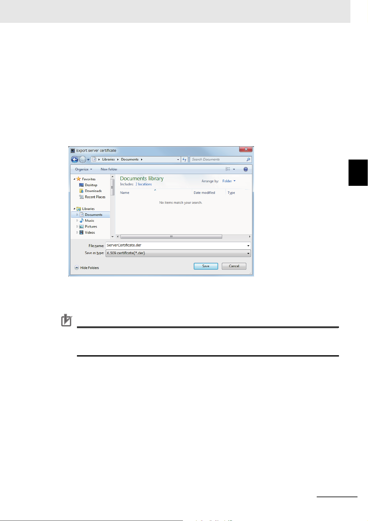
3 Settings of the OPC UA Server
Precautions for Correct Use
Updating Server Certificate Tab Page
The display on the Server Certificate Tab Page is updated with the data in the CPU Unit connected
online.
1 Click the Update Button to reacquire the Server Certificate in the CPU Unit and update the
Server Certificate Tab Page display.
Exporting Server Certificate
The server certificate is exported as X.509 certificate file.
1 When you click the Export Button, the following Export server certificate Dialog Box is dis-
played.
• The file type is X.509 certificate, and the identifier is *.der.
• The default filename is ServerCertificate.der.
3-2 OPC UA Settings
3
3-2-5 Setting and Displaying the Certificate
2 Click the Save Button to save the Server certificate file in the specified path.
If you replace the CPU Unit or change the IP address of the CPU Unit and regenerate the
Server certificate, export the Server certificate by the above operation and import it to the OPC
UA client.
Regenerating the Server Certificate
If you set the DN (Distinguished Name) information of the Server certificate and the validity period,
you can regenerate the Server certificate in the CPU Unit manually.
The value of the IP address of the server certificate is generated from the IP address of the built-in
EtherNet/IP port at the time of regeneration.
If you change the IP address after the server certificate is generated automatically, be sure to regenerate the server certificate manually. If the IP address of the server certificate does not match the IP
address of the built-in EtherNet/IP port, OPC UA clients can not connect to the OPC UA Server.
NJ/NX-series CPU Unit OPC UA User’s Manual (W588)
3 - 13
Page 56
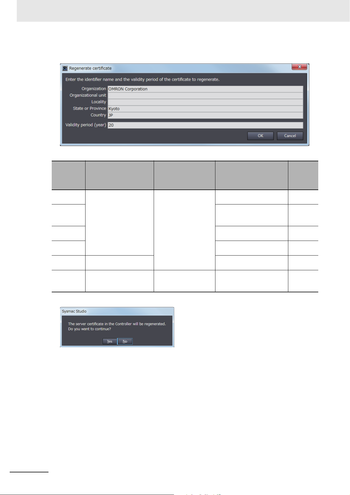
3 Settings of the OPC UA Server
1 When you click the Regenerate certificate Button, the following Regenerate certificate Dialog
Box is displayed.
2 Set the following items.
Item
Organization name
Organizational unit
name
Municipality Kyoto Cannot be
Prefecture Kyoto Cannot be
Country Two half-width alphabetic
Val idity
period
(years)
Effective character
/range
0 to 9, a to z, A to Z, halfwidth space [ ], hyphen [-],
dot [.], Underscore [_],
comma [,], slash [/], parenthesis [(], closing parenthesis [)]
Within 64 characters.
characters
An integer from 1 to 20 20 20 Cannot be
Default value dis-
played on the Sysmac
Studio
Value stored in the subject of the Certificate
being displayed
OPC UA Server is set to
Use, and default value
when the Controller power
is turned on
OMRON Corporation Cannot be
--- Can be
JP Cannot be
Omission
omitted
omitted
omitted
omitted
omitted
omitted
3 When you click the OK Button, the following confirmation dialog box is displayed.
3 - 14
4 Click the Yes Button to regenerate the server certificate in the CPU Unit in the entered DN infor-
mation and valid period. Click the No Button to close the confirmation dialog box and return to
the state before execution.
After the server certificate is regenerated, communications with OPC UA clients can not be performed as it is. To communicate with the OPC UA clients, export the server certificate and install
it on the OPC UA client side. For information on how to export server certificates, refer to
Exporting Server Certificate on page 3-13.
NJ/NX-series CPU Unit OPC UA User’s Manual (W588)
Page 57
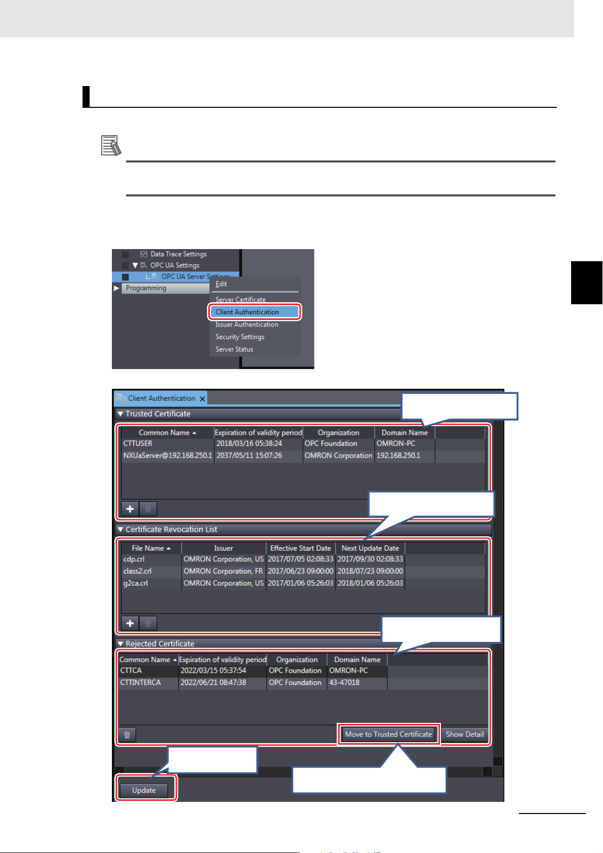
3 Settings of the OPC UA Server
Additional Information
(E) Update Button
(C) Rejected Certificate List
(A) Trusted Certificate List
(D) Move to Trusted Certificate Button
(B) Certificate Revocation List
Client Authentication
You can display and operate self-signed client certificates in the CPU Unit connected online.
For the CA-signed client certificate, refer to the A-3 When CA-signed Client Certificates Sup-
ported on page A-13.
1 In the Sysmac Studio, connect online to the CPU Unit, right-click OPC UA Server Settings
under Configurations and Setup - OPC UA Settings in Multiview Explorer and select Client
Authentication.
The following Client Authentication Tab Page is displayed.
3-2 OPC UA Settings
3
3-2-5 Setting and Displaying the Certificate
NJ/NX-series CPU Unit OPC UA User’s Manual (W588)
3 - 15
Page 58

3 Settings of the OPC UA Server
The following contents are displayed.
Parameter Description
(A) Trusted Certificate List
(B) Certificate
Revocation List
(C) Rejected
Certificate List
(D) Move to
Trusted Certificate Button
(E) Update Button
The Trusted Client Certificate List in the CPU Unit is displayed.
• Common name, expiration of validity period, organization, domain name are displayed.
• The default display order is ascending order of common names. You can sort the list by the
name of each item by clicking each column header. Ascending and descending order are
switched each time you click.
• Add Button ( ):
Adds the certificate selected in the Add Certificate Dialog Box to the Trusted Certificate
List in the CPU Unit. For details, refer to the Adding a Client Certificate (Transfer to the CPU
Unit) below.
• Delete Button ( ):
Deletes the selected certificate from the Trusted Certificate List in the CPU Unit.
For details, refer to the Deleting a Client Certificate below.
• Show Detail Button:
Display details of the selected certificate.
The Certificate Revocation List is used only for CA-signed client certificate.
For details, refer to the A-3 When CA-signed Client Certificates Supported on page A-13.
The rejected client certificate list in the CPU Unit is displayed.
• Delete Button ( ):
Deletes the selected certificate from the Rejected Certificate List in the CPU Unit.
• Show Detail Button:
Display details of the selected certificate.
The Rejected Certificate List in the CPU Unit is moved to the Trusted certificate.
• Move to Trusted Certificate Button:
Move the certificate selected in the Rejected Certificate List to the Trusted Certificate.
For details, refer to Permitting a Rejected Client Certificate on page 3-19 below.
The display in the Client Authentication Tab Page is updated with the data in the CPU Unit.
For details, refer to Updating the Client Authentication Tab Page on page 3-21 below.
Adding a Client Certificate (Transfer to the CPU Unit)
The client certificate file (extension .der) in the computer is added to the Trusted Certificate List in
the CPU Unit.
1 Click the Add Button ( ). The following Add Certificate Dialog Box is displayed.
3 - 16
NJ/NX-series CPU Unit OPC UA User’s Manual (W588)
Page 59

3 Settings of the OPC UA Server
3-2 OPC UA Settings
3
3-2-5 Setting and Displaying the Certificate
2 Select one or more client certificate files (extension .der) to be added, and click the Open But-
ton.
The following dialog box to confirm the execution is displayed.
3 If you click the Yes Button, the selected client certificate is added to the Trusted Certificate List
in the CPU Unit.
When the addition is successful, the following confirmation dialog box is displayed.
NJ/NX-series CPU Unit OPC UA User’s Manual (W588)
3 - 17
Page 60

3 Settings of the OPC UA Server
Precautions for Safe Use
If the addition fails, the following confirmation dialog box is displayed.
• When the client certificate already exists in the Rejected Certificate List
If the client certificate to be added already exists in the Rejected Certificate List in the CPU
Unit, the following confirmation dialog box is displayed.
• When the client certificate already exists in the Trusted Certificate List
If the client certificate to be added already exists in the Trusted Certificate List in the CPU
Unit, the following confirmation dialog box is displayed.
• When the transfer fails
If the client certificate cannot transfer when you cannot open a client certificate file to be
added, the following confirmation dialog box is displayed.
Even if you accidentally add the client certificate of a client for which you do not want to permit
connection in the Trusted Certificate List, the OPC UA Server of the NJ/NX-series Controller
will permit connections from that client.
As a result, confidential information on the server side may be leaked or unintended operation
may be performed. Therefore, when you add a certificate to the Trusted Certificate List from the
Sysmac Studio, make sure that all the certificates that you will register in the Trusted Certificate
List are trusted client certificates.
3 - 18
NJ/NX-series CPU Unit OPC UA User’s Manual (W588)
Page 61

3 Settings of the OPC UA Server
Additional Information
Deleting a Client Certificate
You can delete the selected client certificate in the CPU Unit. You can delete a certificate in the
Trusted Certificate List and the Rejected Certificate List.
1 Select the client certificate you want to delete and click the Delete Button ( ). The following
confirmation dialog box is displayed.
2 Click the Yes Button to delete the client certificate in the CPU Unit.
3-2 OPC UA Settings
Permitting a Rejected Client Certificate
You can move the selected client certificate from the Rejected Certificate List to the Trus ted Certificate List in the CPU Unit.
1 Select the client certificate you want to move, and click the Move to Trusted Certificate Button.
The following Processing Dialog Box is displayed.
2 After a while, the client certificate in the CPU Unit is moved and the Client Authentication Ta b
Page display is updated to the latest information.
If the move fails, the following confirmation dialog box is displayed.
3
3-2-5 Setting and Displaying the Certificate
Automatic Addition of Client Certificates to the Rejected Certificate List
When an OPC UA client connects to the OPC UA Server and the client does not exist in the
Trusted Certificate List, the client's certificate is automatically added to the Rejected Certificate
List.
NJ/NX-series CPU Unit OPC UA User’s Manual (W588)
3 - 19
Page 62

3 Settings of the OPC UA Server
Displaying the Detailed View of Certificates
If you want to display the detailed contents of the selected client certificate, perform the following
operations.
1 Click the Show Detail Button.
The Processing Dialog Box is displayed.
2 After a while, the detailed contents of the client certificate in the CPU Unit are displayed.
If the certificate details display fails, the following confirmation dialog box is displayed.
3 - 20
NJ/NX-series CPU Unit OPC UA User’s Manual (W588)
Page 63

3 Settings of the OPC UA Server
Additional Information
Updating the Client Authentication Tab Page
The display on the Client Authentication Tab Page is updated with the data in the CPU Unit connected online.
1 Click the Update Button to reacquire the Client Certificate List in the CPU Unit and update the
Client Authentication Tab Page display.
When a new OPC UA client connects to the server while a client certificate is displayed and
operated, and the client does not exist in the Trusted Certificate List, the client's certificate will
be automatically added to the Rejected Certificate List. In such a case, it is necessary to update
the Client Authentication Tab Page.
3-2 OPC UA Settings
Issuer Authentication
You can display and operate the certificate authority itself that signed the client certificate in the CPU
Unit connected online. For details, refer to the A-3 When CA-signed Client Certificates Supported on
page A-13.
3
3-2-5 Setting and Displaying the Certificate
NJ/NX-series CPU Unit OPC UA User’s Manual (W588)
3 - 21
Page 64
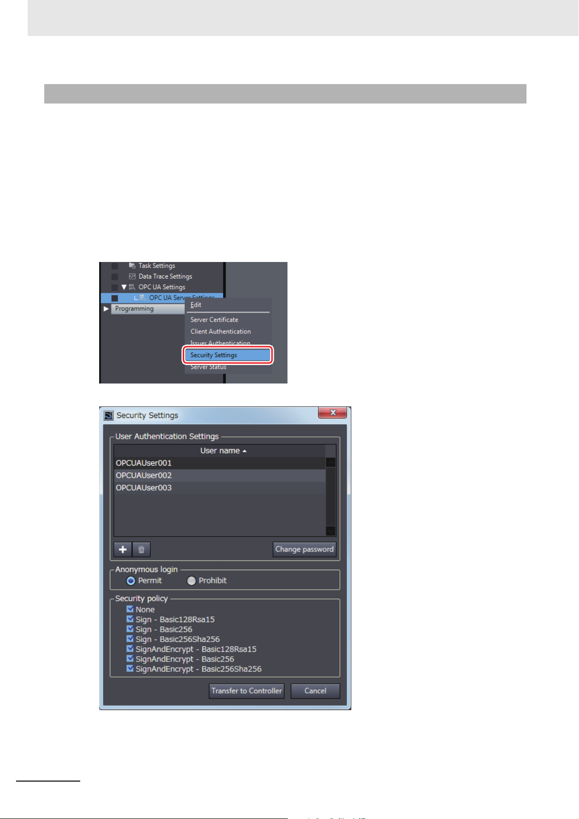
3 Settings of the OPC UA Server
3-2-6 Security Settings
The following shows how to make the security settings and their contents.
The Security settings consist of the following contents.
• User Authentication Settings
• Anonymous login
• Security Policy
The Security settings can be operated only when online, and only by the Administrator in the operation
authority verification settings.
1 In the Sysmac Studio, connect online to the CPU Unit, right-click OPC UA Server Settings
under Configurations and Setup - OPC UA Settings in Multiview Explorer and select Secu-
rity Settings from the menu.
The following Security Settings Dialog Box is displayed.
3 - 22
NJ/NX-series CPU Unit OPC UA User’s Manual (W588)
Page 65

3 Settings of the OPC UA Server
Item Valid character Range of characters Default
User name 0 to 9, a to z, A to Z (case sensitive)
Note: The following are reserved words and cannot be set (not
case sensitive).
• Administrator
• Designer
• Maintainer
• Operator
• Observer
• Anonymous
4 to 32 characters Blank
Password 0 to 9, a to z, A to Z (case sensitive) 8 to 32 characters Blank
Confirm New
Password
Same as above password. Same as above pass-
word.
Blank
Set the following items.
Parameter Description Set value Default
User
Authentication Settings
The list of configured user names is displayed.
• The default display order is the order
stored in the user name setting file. You
User name
word (up to 20 people)
can sort by clicking the header of the
user name. Ascending and descending
order are switched each time you click.
• Add Button ( ):
Adds the user name. For details, refer to
Adding a User Name on page 3-24.
• Delete Button ( ):
Deletes the selected user name.
• Change password Button:
Changes the password of the currently
selected user name. For details, refer
to Changing the Password on page
3-24 below.
Anonymous login
Security
Policy
Sets whether to prohibit or permit anonymous logins.
Set the allowable range as the server of
the Security Mode and Policy in the OPC
UA specifications.
Multiple checks are possible.
For details on the specified items, refer to
5-2-2 OPC UA Security Mode and Policy
on page 5-7.
•Prohibit
•Permit
• None
• Sign - Basic128Rsa15
• Sign - Basic256
• Sign - Basic256Sha256
• SignAndEncrypt Basic128Rsa15
• SignAndEncryptBasic256
• SignAndEncrypt Basic256Sha256
Transfer to
Controller
Button
Transfer the Security Settings (User
authentication settings, anonymous login,
and security policy) to the CPU Unit. For
--- --- --- ---
details, refer to Transfering the Security
Settings on page 3-25 below.
*1. The restrictions on each entry of user name and password are as follows.
*1
and pass-
None When click-
Pro-
hibit
None is
not
selected.
*3
Other
items are
selected.
*2
Update
Timing
ing the
Transfer to
Controller
Button
Changes in
RUN mode
Not
allowed.
3-2 OPC UA Settings
3
3-2-6 Security Settings
NJ/NX-series CPU Unit OPC UA User’s Manual (W588)
3 - 23
Page 66
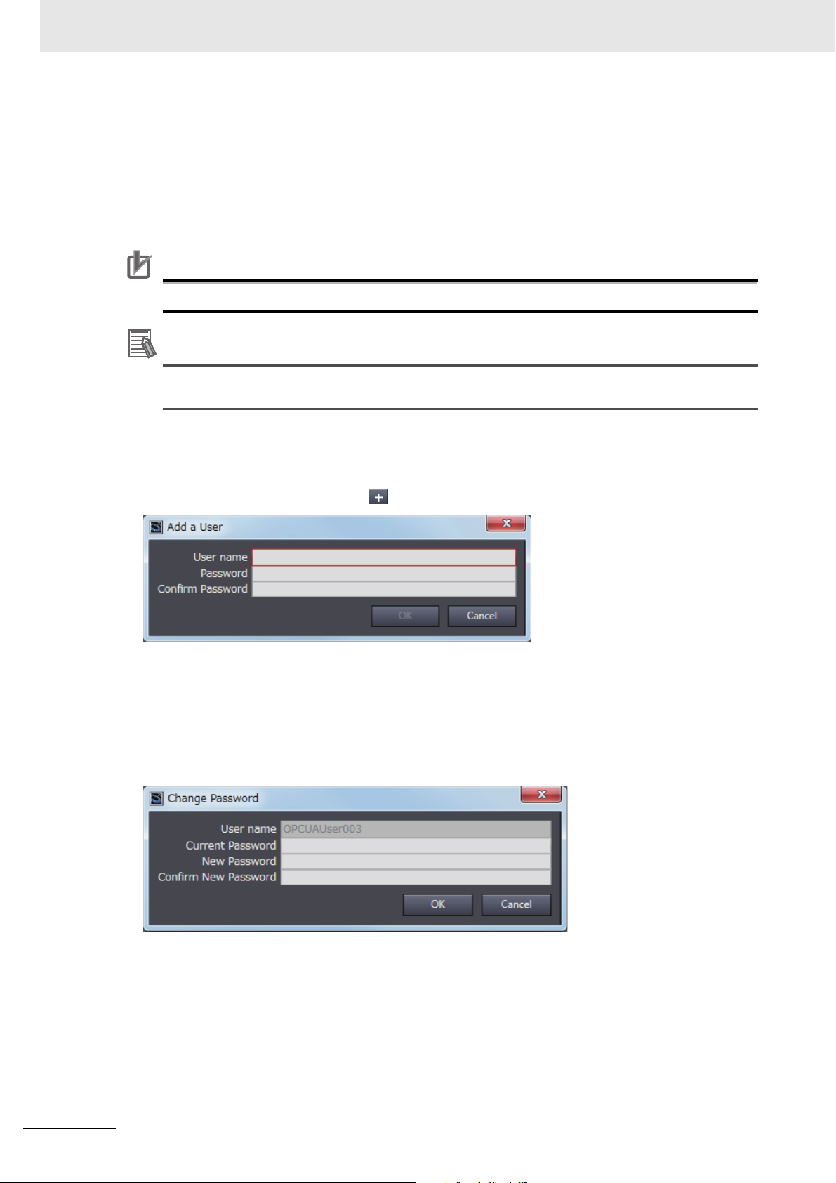
3 Settings of the OPC UA Server
Precautions for Correct Use
Additional Information
*2. For the CPU Units with unit versions shown below, the default setting is Permit.
NJ501-100 : Unit version earlier than 1.43
NX102-00 : Unit version earlier than 1.43
NX102-20 : Unit version earlier than 1.36
*3. For the CPU Units with unit versions shown below, the default setting for None is selected.
NJ501-100 : Unit version earlier than 1.43
NX102-00 : Unit version earlier than 1.43
NX102-20 : Unit version earlier than 1.36
When you take security into consideration, be sure to clear None under Security Policy.
If the OPC UA communications cannot be performed normally, check the consistency of anonymous login setting and security policy setting between the Controller and OPC UA client.
Adding a User Name
Add a user name.
1 When you click the Add Button( ), the following Add a User Dialog Box is displayed.
2 In the User name field, enter the user name, and enter the password in the Password and
Confirm Password fields, and then click the OK Button.
Changing the Password
Change the password of the currently selected user name.
1 Click the Change password Button, the following Change Password Dialog Box is displayed.
2 Enter the password in the fields of Current Password, New Password, and Confirm New
Password, and click the OK Button.
3 - 24
NJ/NX-series CPU Unit OPC UA User’s Manual (W588)
Page 67
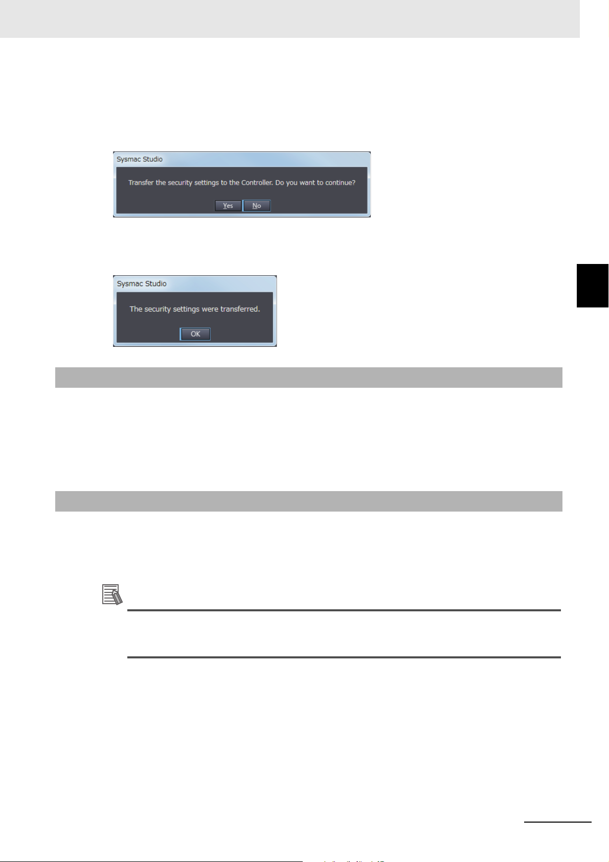
3 Settings of the OPC UA Server
Additional Information
Transfering the Security Settings
The Security Settings (user authentication setting, anonymous login, and security policy) displayed
in the Security Settings Tab Page are transferred to the CPU Unit.
1 Click the Transfer to Controller Button. The following dialog box is displayed.
2 Click the Yes Button to transfer the User name and Password displayed in the User Authentica-
tion Settings to the CPU Unit.
When the transfer is successful, the following confirmation dialog box is displayed.
3-2 OPC UA Settings
3
3-2-7 Server Status
3-2-7 Server Status
You can check the status of the OPC UA Server such as the operating status of the OPC UA Server
and the number of connected clients.
You can also instruct the shutdown of the OPC UA Server from the Sysmac Studio.
For details, refer to 4-2-1 Checking Based on OPC UA Server Status of the Sysmac Studio on page
4-5.
3-2-8 Displaying the Operation Logs
You can display a list of the Execution Logs in the SD Memory Card mounted in the CPU Unit and operate the list.
For details, refer to 7-2-2 Checking Logs in the Operation Log Window in the Sysmac Studio on page
7-13.
In view of future expansion of functions, in the Sysmac Studio, the display of the Execution
Logs is placed under the Operation Log Display as the lower level of the upper concept Opera-
tion Log.
NJ/NX-series CPU Unit OPC UA User’s Manual (W588)
3 - 25
Page 68

3 Settings of the OPC UA Server
3-2-9 Operations for the OPC UA Settings
The following table shows whether the setting data of the OPC UA Settings is applied for each operation of synchronization (transfer), backup or restore, or Clear All Memory.
OK: Applicable, AS:Applicable by selection, NA: Not applicable
Operations
Backup Restore
One of the fol-
Synchroni-
Setting data of
OPC UA Settings
OPC UA Server settings OK OK OK OK Clear
Server certificate NA NA NA NA Select whether
OPC UA
security
profile
Execution Log NA NA NA NA Do not clear
*1. Client certificates, CA certificates, Certificate Revocation Lists, and Security Settings are not applicable when exporting
and importing backup files in the Sysmac Studio.
*2. Whether to restore or not can be selected below.
When the SD Memory Card backup function is used: Depends on the restore command file (RestoreCommand.ini).
When the Sysmac Studio Controller backup function is used: Depends on selecting the data to restore in the Restore
Dialog Box.
Client certificate NA
CA certificate
Certificate
Revocation List
Security settings
(User authentication settings, anonymous login, and
security policy)
zation
(transfer)
from the
Sysmac
Studio
lowing cases:
• SD Memory
Card Backup
functions
• Sysmac Studio
Controller
backup functions
*1
OK
When one of the
following methods is used:
• SD Memory
Card Backup
function
• Sysmac Studio
Controller
Backup function
*2
AS
When one of the
following methods is used:
• Automatic
transfer from
SD Memory
Card
• Program transfer from SD
Memory Card
NA
Clear All
Memory operation from the
Sysmac Stu-
dio
to clear or not.
3 - 26
NJ/NX-series CPU Unit OPC UA User’s Manual (W588)
Page 69
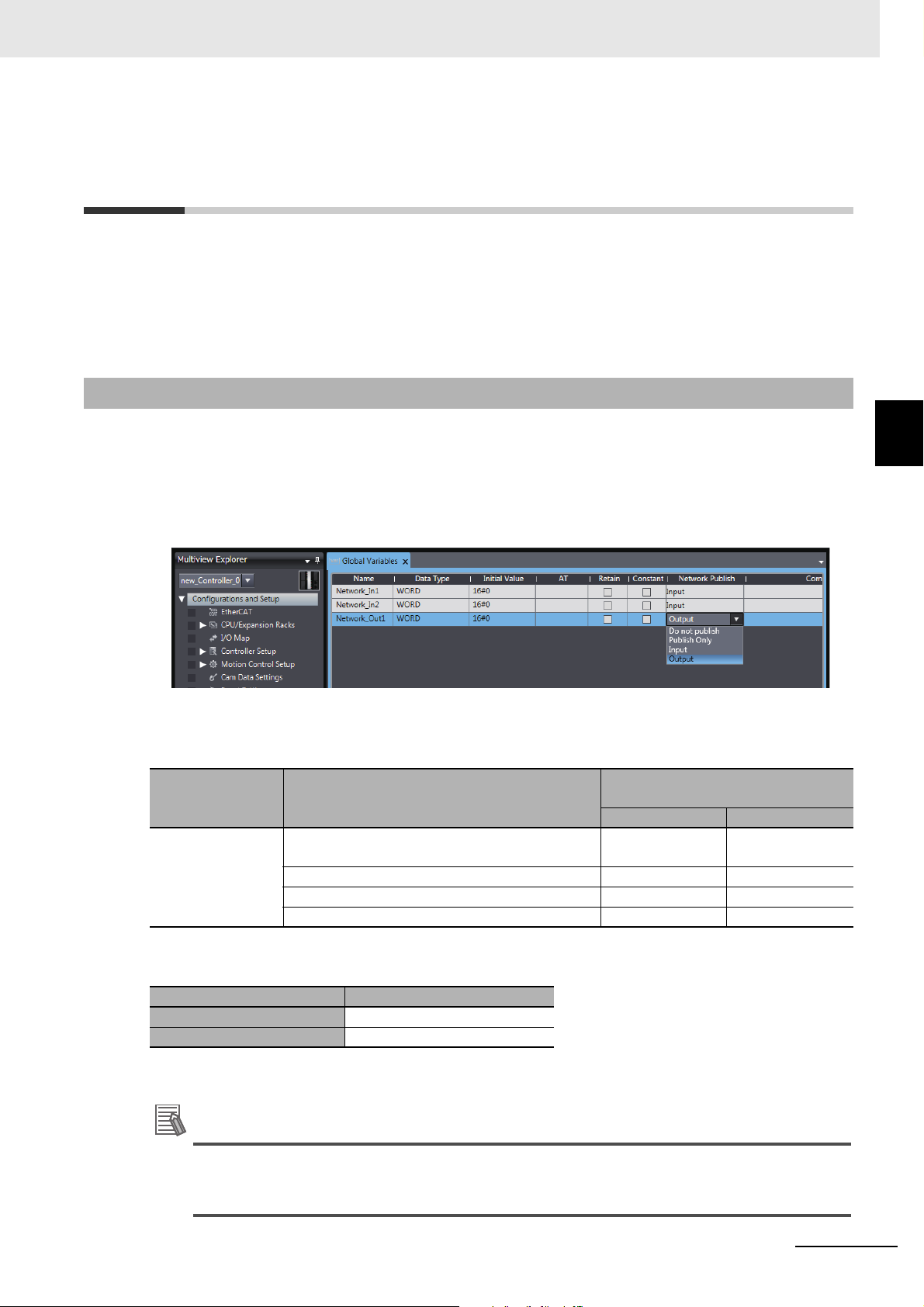
3 Settings of the OPC UA Server
Additional Information
3-3 Creating Variables for OPC UA Com-
munications
This section describes how to create variables for OPC UA communications.
*1
The variables that can be published to OPC UA communications are the global variables
*1. System-defined variables can not be published to OPC UA communications.
3-3-1 Global Variables Published to OPC UA Communications
.
3-3 Creating Variables for OPC UA Communications
To publish global variables to the OPC UA communications, the attributes of variables is set to Network
Publish Attribute.
1 In the Global Variable Editor of the Sysmac Studio, set the Network Publish attribute of the
global variable to Public Only, Input, or Output.
Variables in which these attributes are set are called variables published to the network.
If a variable is published to the network, it can be read and written from the OPC UA client.
The possibility of reading from or writing to the OPC UA client in accordance with the network publish
attribute is as follows.
Attributes of Variables
Network Publish
Attribute
The following table shows the maximum number of variables and value attributes with the Network
Publish attribute that can be published to clients as an OPC UA Server.
Item Maximum number
Number of public variables 10,000
Number of value attributes 10,000
For details of the data types that can be published, refer to 6-2 Reading/Writing Variables from the OPC
UA Client on page 6-3.
Set value
Do not publish (default value in the Sysmac Studio).
Publish Only Yes Yes
Input Yes Yes
Output Yes Yes
Possibility of reading from or writing to the OPC UA client
Read Write
No No
3
3-3-1 Global Variables Published to OPC UA Communications
Publish Only, Input, and Output in the Network Publish attribute are settings shared with EtherNet/IP communications. As for OPC UA communications, there is no difference between Pub-
lish Only, Input, and Output.
NJ/NX-series CPU Unit OPC UA User’s Manual (W588)
3 - 27
Page 70

3 Settings of the OPC UA Server
3-3-2 Adding or Deleting Network-published Variables
You can add or delete network-published variables in either of the following ways:
• Downloading (synchronization) after editing the global variable table offline
• Online editing
3 - 28
NJ/NX-series CPU Unit OPC UA User’s Manual (W588)
Page 71

Starting and Checking the Status
of the OPC UA Server
This section describes how to start or stop the OPC UA Server, and also how to check
the status of the OPC UA Server.
4-1 Starting or Stopping the OPC UA Server . . . . . . . . . . . . . . . . . . . . . . . . . . . 4-2
4-1-1 How to Start or Stop the OPC UA Server . . . . . . . . . . . . . . . . . . . . . . . . . . . . 4-2
4-1-2 Conditions under Which the OPC UA Server Cannot be Started . . . . . . . . . . 4-3
4-1-3 Conditions under Which the OPC UA Server Stops . . . . . . . . . . . . . . . . . . . . 4-3
4-1-4 Operation of the OPC UA Service Function in each State of the CPU Unit . . 4-4
4-2 Checking the Status of the OPC UA Server . . . . . . . . . . . . . . . . . . . . . . . . . 4-5
4-2-1 Checking Based on OPC UA Server Status of the Sysmac Studio . . . . . . . . 4-5
4-2-2 Checking Based on the Event Log . . . . . . . . . . . . . . . . . . . . . . . . . . . . . . . . . 4-7
4-2-3 Checking Based on the Execution Log . . . . . . . . . . . . . . . . . . . . . . . . . . . . . . 4-7
4-2-4 Operating Status of the OPC UA Server . . . . . . . . . . . . . . . . . . . . . . . . . . . . 4-7
4-2-5 Conditions for Reconfiguring the OPC UA Server . . . . . . . . . . . . . . . . . . . . . 4-9
4
NJ/NX-series CPU Unit OPC UA User’s Manual (W588)
4 - 1
Page 72

4 Starting and Checking the Status of the OPC UA Server
Precautions for Correct Use
4-1 Starting or Stopping the OPC UA
Server
This section describes how to start or stop the OPC UA Server.
4-1-1 How to Start or Stop the OPC UA Server
The method of starting and stopping the OPC UA Server and the method of starting the OPC UA
Server after stopping it are described below.
Starting the OPC UA Server
The method of starting the OPC UA Server is as below.
1 In the Multiview Explorer of the Sysmac Studio, double-click OPC UA Server Settings under
Configurations and Setup - OPC UA Settings. Or, right-click OPC UA Server Settings and
select Edit from the menu.
2 Select Use Option for OPC UA Server under OPC UA Settings - OPC UA Server Settings.
The factory default setting is Do not use (Stop).
3 Place the Sysmac Studio online with the CPU Unit and download (synchronize) OPC UA Set-
tings.
4 Cycle the power supply to the Controller or reset the Controller.
The OPC UA Server Use Option is enabled and the OPC UA Server starts.
When you download (synchronize) or restore the OPC UA Settings by changing OPC UA
Server to Use from Do not use, you must either cycle the power supply to the Controller or reset
the Controller in order to start the OPC UA Server. The OPC UA Server will not start unless you
cycle the power supply to the Controller or reset the Controller.
Stopping the OPC UA Server
Either of the following methods can be used to stop the OPC UA Server.
Method a) Executing the OPCUA_Shutdown (Shutdown OPC UA Function)
instruction from the user program
For the OPCUA_Shutdown (Shutdown OPC UA Function) instruction, refer to A-2-1 OPCUA_Shutdown (Shutdown OPC UA Function) on page A-9.
Method b) Shutting down from the Sysmac Studio
1 Place the Sysmac Studio online with the CPU Unit, right-click OPC UA Server Settings under
Configurations and Setup - OPC UA Settings in the Multiview Explorer, and then select
Server Status.
2 Click the Server shutdown Button.
4 - 2
NJ/NX-series CPU Unit OPC UA User’s Manual (W588)
Page 73

4 Starting and Checking the Status of the OPC UA Server
Additional Information
Starting the OPC UA Server after Stopping It
To start the OPC UA Server after shutting it down, either cycle the power supply to the Controller or
reset the Controller.
4-1-2 Conditions under Which the OPC UA Server Cannot be Started
The OPC UA Server cannot be started in the following cases.
• When the OPC UA Server is in the Halt error state
• When the Controller power is not turned ON again, or the Controller is not reset after the OPC UA
Server is in Shutdown state
• When the Controller power is not turned ON again or the Controller is not reset after the OPC UA
Server is changed from Use to Do not use and the OPC UA Settings are downloaded (synchronized)
or restored.
4-1-3 Conditions under Which the OPC UA Server Stops
The OPC UA Server stops in the following cases.
• When the OPC UA Server shut down from the Sysmac Studio or the OPCUA_Shutdown (Shutdown
OPC UA Function) instruction is executed
• When the Controller power is turned ON again or the Controller is reset after the OPC UA Server is
changed from Use to Do not use and the OPC UA Settings are downloaded (synchronized) or
restored.
• When the data is restored from the SD Memory Card or the Sysmac Studio
• When the Clear All Memory operation is executed from the Sysmac Studio
4-1 Starting or Stopping the OPC UA Server
4
4-1-2 Conditions under Which the OPC UA Server Cannot be Started
• The OPC UA Server continues to operate even when a major fault level Controller error
occurs.
• When a Controller error occurs and you refer to the address space of the NJ/NX-series Controller from the OPC UA client, you can check the following from ErrorStatus under DeviceS-
tatus.
• NoError: Normal
• MajorFault: Major fault
• ContinuousError: Partial fault or minor fault
NJ/NX-series CPU Unit OPC UA User’s Manual (W588)
4 - 3
Page 74

4 Starting and Checking the Status of the OPC UA Server
4-1-4 Operation of the OPC UA Service Function in each State of the
CPU Unit
The execution state of the OPC UA service function changes depending on the state of the CPU Unit.
The operation of the OPC UA service function in the startup state, normal operation, and error state is
described below.
Process of CPU Unit OPC UA Service function
Operation during startup state Stopped.
Operation during normal operation
Error state Major fault Executed. However, stopped during a
PROGRAM mode Executed.
RUN mode Executed.
Downloading Stopped.
During online editing Executed.
During backup Executed.
During restore operation, after restore oper-
ation
During execution of Clear All Memory operation, after execution of Clear All Memory
operation
Partial fault Executed. However, stopped during an
Minor fault Executed. However, may be stopped
Stopped. The power supply must be
cycled or the Controller must be reset
after restoring data.
Stopped. The power supply must be
cycled or the Controller must be reset
after the execution of Clear All Memory
operation.
CPU error (WDT error).
OPC UA Server error.
during an OPC UA Server error.
4 - 4
NJ/NX-series CPU Unit OPC UA User’s Manual (W588)
Page 75

4 Starting and Checking the Status of the OPC UA Server
4-2 Checking the Status of the OPC UA
Server
This section describes how to check the status of the OPC UA Server.
You can use the following methods to check the status of the OPC UA Server.
• OPC UA server status of the Sysmac Studio
• Event log
• Execution Log
4-2-1 Checking Based on OPC UA Server Status of the Sysmac Studio
The method of checking the server status and its contents are described below.
The server status can be operated only in the online state.
1 Place the Sysmac Studio online with the CPU Unit, right-click OPC UA Server Settings under
Configurations and Setup - OPC UA Settings in the Multiview Explorer, and then select
Server Status.
4-2 Checking the Status of the OPC UA Server
4
4-2-1 Checking Based on OPC UA Server Status of the Sysmac Studio
The following Server Status Tab Page is displayed.
You can check the following states unless the operating status of the OPC UA Server is Initializ-
ing or Shutdown.
NJ/NX-series CPU Unit OPC UA User’s Manual (W588)
4 - 5
Page 76

4 Starting and Checking the Status of the OPC UA Server
Category Item Description
Operation
Information
Buttons Update Button Acquires the operation information from the server and updates the Server
OPC UA Server Displays the setting status of the OPC UA Server.
Any one of the following is displayed.
•Use
• Do not use
Server operating
status
End point Displays the end point of the OPC UA Server.
Number of connected clients
Number of connected users
Server shutdown
Button
Displays the operating status of the OPC UA Server.
Any one of the following is displayed.
• Initializing
• Preparing
• Running
• Halt error
• Shutdown
Refer to 4-2-5 Conditions for Reconfiguring the OPC UA Server on page 4-9
for details on the operating status
• The end point is displayed only when the server operating status is Run-
ning.
• When the server operating status is other than the above, “---” is displayed.
Displays the number of currently connected OPC UA clients.
• “---” is displayed only when the server operating status is Initializing.
• When the server operating status is other than the above, the number of
connected clients is displayed.
Displays the number of currently connected users.
Status Tab Page.
Shuts down the server function.
For details, refer to Shutting Down the Server Function below.
Shutting Down the Server Function
Shutdown the OPC UA Server.
1 When you click the Server shutdown Button, the following confirmation dialog box is displayed.
2 Click the Yes Button. The following dialog box is displayed.
4 - 6
NJ/NX-series CPU Unit OPC UA User’s Manual (W588)
Page 77

4 Starting and Checking the Status of the OPC UA Server
Shutdown
Initializing
Use
Running
OPC UA Server starts
Halt error
A setting error is detected
Turn ON the
Controller power
or reset the
Controller
Note: In the following cases, you must cycle the power supply to
the Controller or reset the Controller.
· When OPC UA Server is changed
from Do not use to Use and the data is downloaded or restored
· When a Clear All Memory operation is executed while OPC UA
Server is set to Use
When
OPC UA Server
is set to...
· Shut down
· Clear All Memory
Or
· OPC UA Server is set to Do not Use, and
data is downloaded
· Shutdown
·Clear All Memory
Or
·OPC UA Server is set to Do not Use,
and data is downloaded
OPC UA Server is set to Use, and data is
downloaded
Preparing
Preparation
completed
The end point settings are changed or OPC UA
Server is set to Use, then data is downloaded
Data is downloaded, but a
setting error is detected
Do not use
4-2-2 Checking Based on the Event Log
You can check the operating status of the OPC UA Server by the event log of the Controller.
For details, refer to the NJ/NX-series Troubleshooting Manual (Cat. No. W503).
4-2-3 Checking Based on the Execution Log
You can check the operating status of the OPC UA Server by the Execution Log function of the OPC
UA Server.
For details, refer to Section 7 Execution Log Functions.
4-2-4 Operating Status of the OPC UA Server
This section describes the operating status of the OPC UA Server.
The OPC UA Server has five operation states, such as Initializing, Preparing, Running, Halt error, and
Shutdown. The operating status transits as shown in the figure below.
4-2 Checking the Status of the OPC UA Server
4
4-2-2 Checking Based on the Event Log
NJ/NX-series CPU Unit OPC UA User’s Manual (W588)
4 - 7
Page 78

4 Starting and Checking the Status of the OPC UA Server
• If the OPC UA server is set to Use after the Controller power is turned ON *1, the OPC UA Server
enters the Initializing state. When the initialization process is complete, the OPC UA Server enters
the Preparing state, then it shifts to the Running state after the completion of preparation.
• In the Running state, if the OPC UA Server is shutdown
and data is downloaded, the OPC UA Server shifts to the Shutdown state.
*1. In the following cases, you must cycle the power supply to the Controller or reset the Controller.
• When OPC UA Server is changed from Do not use (setting in the CPU Unit) to Use and the data
is downloaded or restored*
* It includes both the Restore operation executed from the SD memory card and the Restore
operation executed from the Sysmac Studio.
• When a Clear All Memory operation is executed while OPC UA Server is set to Use (setting in
the CPU Unit)
*2. When shutdown of the OPC UA Server is instructed from the Sysmac Studio, or when the OPCUA_Shutdown
(Shutdown OPC UA Function) instruction is executed.
*2
, or if OPC UA server is set to Do not Use
The details of each status are given below.
Status Description Remarks
Initializing This is the status in which the initial
processing of the OPC UA Server is
executed.
Preparing This is the status in which the OPC
UA Server is prepared.
Running This is the status in which the OPC
UA Server is running.
Halt error This is the status in which the OPC
UA Server is stopped due to a setting error.
Shutdown This is the state while the OPC UA
Server is processing to shut down,
or when the OPC UA Server has
shutdown.
The OPC UA server settings are read, and each function
or monitor is initialized.
The Controller shifts to this status when the OPC UA
Server is used.
Configuration of the end point and configuration of the
address space (variables to be published) is performed
in this status. This is the status in which requests from
the OPC UA client cannot be accepted.
The Controller shifts to this status when the configuration
of the OPC UA Server is completed.
This is the status in which requests from the OPC UA client can be accepted.
The Controller shifts to this status when a setting error is
detected during initialization, or when a download is executed during operation, and a setting error exists in the
data.
The Controller shifts to this state in the following cases:
• When shutdown of the OPC UA Server is instructed
from the Sysmac Studio, or when the OPCUA_Shutdown (Shutdown OPC UA Function) instruction is executed
• OPC UA Server is set to Do not Use, and data is
downloaded
After the shutdown processing of the OPC UA Server is
completed, the user can safely turn OFF the power supply to the Controller. The OPC UA Server cannot be
started until you cycle the power supply to the Controller
or reset the Controller.
4 - 8
NJ/NX-series CPU Unit OPC UA User’s Manual (W588)
Page 79

4 Starting and Checking the Status of the OPC UA Server
Additional Information
4-2-5 Conditions for Reconfiguring the OPC UA Server
The OPC UA Server is reconfigured if the following changes are made while the OPC UA Server is running.
• When synchronization (download) is executed
• When the restore operation is executed
• When the IP address of the built-in EtherNet/IP port is changed
• When the server certificate is regenerated
• When the security settings are updated
Even if a network-published variable is added by online editing while the OPC UA Server is runnning, the OPC UA Server is not reconfigured, and the network-published variable is added to
the existing address space. In that case, OPC UA clients can access to the variable that you
have added.
4-2 Checking the Status of the OPC UA Server
4
4-2-5 Conditions for Reconfiguring the OPC UA Server
NJ/NX-series CPU Unit OPC UA User’s Manual (W588)
4 - 9
Page 80

4 Starting and Checking the Status of the OPC UA Server
4 - 10
NJ/NX-series CPU Unit OPC UA User’s Manual (W588)
Page 81

Security Function of OPC UA
Server
This section describes the security function of the OPC UA Server.
5-1 Details of the Connection Authentication
Function of the OPC UA Server . . . . . . . . . . . . . . . . . . . . . . . . . . . . . . . . . . 5-2
5-1-1 Application Authentication . . . . . . . . . . . . . . . . . . . . . . . . . . . . . . . . . . . . . . . 5-2
5-1-2 User Authentication . . . . . . . . . . . . . . . . . . . . . . . . . . . . . . . . . . . . . . . . . . . . 5-5
5-2 Details of the Message Security Function . . . . . . . . . . . . . . . . . . . . . . . . . . 5-7
5-2-1 Signature and Encryption . . . . . . . . . . . . . . . . . . . . . . . . . . . . . . . . . . . . . . . . 5-7
5-2-2 OPC UA Security Mode and Policy . . . . . . . . . . . . . . . . . . . . . . . . . . . . . . . . 5-7
5
NJ/NX-series CPU Unit OPC UA User’s Manual (W588)
5 - 1
Page 82

5 Security Function of OPC UA Server
5-1 Details of the Connection Authentica-
tion Function of the OPC UA Server
This section describes the following two stages of connection functions in detail with regard to the con-
5-1-1 Application Authentication
nection authentication function of the OPC UA Server.
Function Description
Application authentication Authentication of applications between the OPC UA server and OPC UA client
User authentication Authentication of the user that operates the client applications of the OPC UA
The OPC UA server and the OPC UA client authenticate each other’s identity by exchanging mutual
digital certificates (hereinafter, called certificates). This is called Application authentication.
In application authentication, the certificates supported by the OPC UA server and the OPC UA client
are X.509-standard certificates.
The certificates supported by the OPC UA Server are of the following three types:
Certificate Description
Server certificate This is a certificate for certifying an OPC UA server. In the case of an OPC UA
server, it is a self-signed certificate.
Client certificate This is a certificate for certifying the OPC UA client.
Both self-signed client certificates and CA-signed client certificates can be used.
CA certificate and Certificate
Revocation List
In the case of a CA-signed client certificate, this certificate is used to authenticate the certificate chain.
In the OPC UA Server, the following functions are enabled for each certificate:
Certificate Function
Server certificate
Client certificate
CA certificate and
Certificate Revocation
List
*1. This operation can be performed only by the Administrator in the operation authority verification settings of the
Sysmac Studio.
• Generation (automatic generation or manual regeneration
(self-signed certificate)
• Export of the server certificate from the CPU Unit
• Advance expiration notice of the server certificate, and notification of expiry
• Authentication of the client certificate during a connection
• Addition of the client certificate (transfer to the CPU Unit)
• Trust or reject setting of the client certificate
• Notification of expiry of client certificate
Used only in the case of a CA-signed client certificate.
For details, refer to A-3 When CA-signed Client Certificates Supported on page A-13.
*1
*1
*1
) of the server certificate
*1
*1
5 - 2
For details on each operation method from the Sysmac Studio, refer to 3-2-5 Setting and Displaying the
Certificate on page 3-11.
NJ/NX-series CPU Unit OPC UA User’s Manual (W588)
Page 83

5 Security Function of OPC UA Server
5-1 Details of the Connection Authentication Function of the OPC UA Server
Server Certificate
In the OPC UA Server, the following functions are enabled for the server certificate.
Generation of the Server Certificate (Self-signed Certificate)
The server certificate can be generated by any of the following methods. Each of these methods is
for a self-signed certificate.
• Automatic generation
If a server certificate does not exist in the CPU Unit when the OPC UA Server is started, the
server certificate is automatically generated.
The contents of the server certificate that is automatically generated are as follows:
Category
Basic information
Detailed
information
*1. For the meaning of each item, refer to X.509.
*1
Item
Issued to NxOpcUaServer@[IPAddress]
Issued by
Valid from The server certificate is valid from the date and time of automatic
Version Version information of the certificate
Serial number Unique to each certificate
Signature algorithm
Issuer CN = NxOpcUaServer@[IPAddress]:, O = Omron Corporation, L =
Valid from Date and time of automatic generation
Valid to Date and time twenty years from the date and time of automatic
Subject Same as the issuer
Public key Public key of the applicant and its types.
Thumbprint Message digest of the CA.
Detailed Text Box Each element of the issuer is displayed in a new line.
Description
[IPAddress] is the IP address of the built-in EtherNet/IP port at the
time of automatic generation.
generation up to the date and time twenty years from the start date
and time
Algorithm of the signature added to the certificate.
Kyoto, S = Kyoto, C=JP
[IPAddress] is the IP address of the built-in EtherNet/IP port at the
time of automatic generation.
generation
5
5-1-1 Application Authentication
• Manual regeneration
By setting the DN (Distinguished Name) information and the valid period of the server certificate, the
server certificate in the CPU Unit can also be manually regenerated.
This function is executed when it is necessary to recreate the server certificate, for example, when
the following events occur:
Server Certificate Mismatch (event code: 15020000 hex)
Server Certificate Expired (event code: 35D10000 hex)
Server Certificate Expiration Notice (event code: 35D20000 hex)
Note that regeneration of the server certificate can be executed only by the Administrator set as the
operation authority.
NJ/NX-series CPU Unit OPC UA User’s Manual (W588)
5 - 3
Page 84

5 Security Function of OPC UA Server
Precautions for Correct Use
When you download to the CPU Unit a project for which OPC UA Server is set to Use in the
OPC UA Settings, and then cycle the power supply to the Controller, the server certificate is
automatically generated by the IP address of the built-in EtherNet/IP port at that time.
Thereafter, when you change the IP address of the built-in EtherNet/IP port, the IP address of
the built-in EtherNet/IP port and the IP address of the server certificate do not match. Therefore, a Server Certificate Mismatch event (event code: 15020000 hex) occurs. In that case,
manually regenerate the server certificate, or set the IP address back to the original address.
Export of the Server Certificate from the CPU Unit
Export the server certificate in the CPU Unit.
This function is executed in cases where the OPC UA client side requires the server certificate
before connecting to the OPC UA server.
Note that export of the server certificate can be executed only by the Administrator set as the operation authority.
Advance Expiration Notice of the Server Certificate, and Notification of Expiry
The CPU Unit performs a notification 30 days before the expiry of the server certificate, and also
when the server certificate expires.
The notification is recorded in the event log and the Execution Log.
Client Certificate
A self-signed client certificate is described below.
For details on using a CA-signed client certificate, refer to A-3 When CA-signed Client Certificates Sup-
ported on page A-13.
In the OPC UA Server, the following functions are enabled for the client certificate.
Authentication of the Client Certificate during a Connection
The OPC UA Server compares the client certificate that is sent during a connection from the OPC
UA client, and the client certificate in the Trusted Certificate List that is set from the Sysmac Studio,
and allows the connection only if the client certificate is set in advance in the Trusted Certificate List.
If the client certificate does not exist, the OPC UA Server saves the client certificate in the Rejected
Certificate List and rejects the connection.
The client certificate is saved in the following locations in the CPU Unit. Each of these locations is
set from the Sysmac Studio.
Save location Description
Trusted Certificate List This is the location where the certificates of the OPC UA client that are allowed
a connection are placed.
Rejected Certificate List This is the location where the certificates of the OPC UA client that are rejected
a connection are placed.
5 - 4
NJ/NX-series CPU Unit OPC UA User’s Manual (W588)
Page 85

5 Security Function of OPC UA Server
Addition of the Client Certificate (Transfer to the CPU Unit)
This function is executed in cases where the OPC UA Server requires the client certificate before
connecting to the OPC UA client.
Note that addition (transfer) of the client certificate to the CPU Unit can be executed only by the
Administrator set as the operation authority.
Automatic Addition of the Client Certificate to the Rejected Certificate List
In the following case, the CPU Unit automatically adds the client certificate of the OPC UA client to
the Rejected Certificate List.
• When the OPC UA client establishes a connection with the OPC UA Server, and when the OPC
UA client does not exist in the Trusted Certificate List in the CPU Unit
Trust or Reject Setting of the Client Certificate
By placing the Sysmac Studio online with the CPU Unit, and moving the client certificate of the CPU
Unit as described below, you can set whether to trust or reject a connection.
Note that the trust or reject settings of the client certificate can be made only by the Administrator
set as the operation authority.
• Settings for allowing a connection
The client certificate is moved from the Rejected Certificate List to the Trusted Certificate.
5-1 Details of the Connection Authentication Function of the OPC UA Server
Notification of Expiry of Client Certificate
The CPU Unit performs a notification when the certificate in the Trusted Certificate List expires.
The notification is recorded in the event log and the Execution Log.
5-1-2 User Authentication
The OPC UA Server authenticates the identity of the user that operates the client applications of the
OPC UA by either of the following methods.
• Authentication based on user name and password
• Authentication based on Anonymous
This is called User authentication.
The OPC UA Server supports Allow access to all in a fixed manner as the user access authority of the
OPC UA.
For details on the operation method from the Sysmac Studio, refer to Adding a User Name and Chang-
ing the Password in 3-2-6 Security Settings on page 3-22.
Authentication Based on User Name and Password
5
5-1-2 User Authentication
Only users for whom the user name and password are matching can connect to the OPC UA Server.
Note that registration, deletion, and change of the user name and password can be executed only by
the Administrator set as the operation authority.
Authentication Based on Anonymous
It is also possible to not perform authentication of the identity of the user that operates the client applications of the OPC UA by the user name and password.
NJ/NX-series CPU Unit OPC UA User’s Manual (W588)
5 - 5
Page 86

5 Security Function of OPC UA Server
Additional Information
If the OPC UA communications cannot be performed normally, check the consistency of anonymous login setting between the Controller and OPC UA client. For details on how to make the
settings, refer to 3-2-6 Security Settings on page 3-22.
5 - 6
NJ/NX-series CPU Unit OPC UA User’s Manual (W588)
Page 87

5 Security Function of OPC UA Server
Precautions for Correct Use
5-2 Details of the Message Security
Function
This section describes the details of the message security function in the OPC UA communications.
In the OPC UA Server, the signature and encryption of messages allowed by the server is set by a
security policy.
5-2-1 Signature and Encryption
• Signature refers to signature information that is added and encrypted to assure the validity of certificates and messages.
• Encryption refers to conversion of a message into a code whose meaning is not understood by a particular method (algorithm) during the transmission and reception of the message so that it is not stolen or modified by a third person during communications.
5-2-2 OPC UA Security Mode and Policy
This is a security mechanism for messages that are allowed during exchange with the OPC UA client.
The signature for the messages, the encryption of messages, and the algorithm for the signature and
encryption are set.
Place the Sysmac Studio online with the CPU Unit, and make the settings as shown below.
In the Multiview Explorer, right-click OPC UA Server Settings under Configurations and Setup -
OPC UA Settings, and then select Security Settings. Under Security Policy, specify the OPC UA
security mode and policy to be allowed from the following. You can select multiple items.
OPC UA security modes and policies
that can be selected
None Neither signature nor encryption are required. Not recommended for
Sign - Basic128Rsa15 A signature is required and
Sign - Basic256 Basic256 is supported as the algorithm
Sign - Basic256Sha256 Basic256Sha256 is supported as the
SignAndEncrypt - Basic128Rsa15 A signature and encryption
SignAndEncrypt - Basic256 Basic256 is supported as the algorithm
SignAndEncrypt - Basic256Sha256 Basic256Sha256 is supported as the
Description
security reasons.
the integrity (measures
against modifications, etc.)
of data is secured.
are required, and the integrity (measures against
modifications, etc.) and reliability (measures against
wiretapping, etc.) of data
are secured.
For details on the OPC UA security mode and policy, refer to the OPC UA specifications.
5-2 Details of the Message Security Function
5
5-2-1 Signature and Encryption
Basic128Rsa15 is supported as the
algorithm of the signature.
of the signature.
algorithm of the signature.
Basic128Rsa15 is supported as the
algorithm of the signature and encryption.
of the signature and encryption.
algorithm of the signature and encryption.
When you take security into consideration, be sure to clear None under Security Policy.
NJ/NX-series CPU Unit OPC UA User’s Manual (W588)
5 - 7
Page 88

5 Security Function of OPC UA Server
Additional Information
If the OPC UA communications cannot be performed normally, check the consistency of security policy setting between the Controller and OPC UA client. For details on how to make the
settings, refer to 3-2-6 Security Settings on page 3-22.
5 - 8
NJ/NX-series CPU Unit OPC UA User’s Manual (W588)
Page 89

Connecting from the OPC UA Client and Reading/Writing Variables
This section describes establishing a connection from the OPC UA client and reading/writing the variables of the OPC UA Server.
6-1 Connecting from the OPC UA Client . . . . . . . . . . . . . . . . . . . . . . . . . . . . . . 6-2
6-1-1 Specifying the URL of the Target OPC UA Server . . . . . . . . . . . . . . . . . . . . . 6-2
6-1-2 Connecting to the Target OPC UA Server . . . . . . . . . . . . . . . . . . . . . . . . . . . 6-2
6-2 Reading/Writing Variables from the OPC UA Client . . . . . . . . . . . . . . . . . . 6-3
6-2-1 Address Space of the NJ/NX-series Controller . . . . . . . . . . . . . . . . . . . . . . . 6-3
6-2-2 Reading/Writing the Variables of the CPU Unit . . . . . . . . . . . . . . . . . . . . . . . 6-5
6
NJ/NX-series CPU Unit OPC UA User’s Manual (W588)
6 - 1
Page 90

6 Connecting from the OPC UA Client and Reading/Writing Variables
Additional Information
6-1 Connecting from the OPC UA Client
This section presents an overview of connecting to the OPC UA Server from the OPC UA client.
Execute the following on the OPC UA server from the OPC UA client.
• Specify the URL of the target OPC UA Server
• Connect to the target OPC UA Server
6-1-1 Specifying the URL of the Target OPC UA Server
Enter opc.tcp://[IP address]:[Port No.]/ as the URL, and specify the end point of the target OPC UA
Server.
As for the URL, enter the URL set in OPC UA Server Settings - End Point under Configurations and
Setup - OPC UA Settings in the Multiview Explorer of the Sysmac Studio.
(By default, opc.tcp://192.168.250.1:4840/ is set.)
6-1-2 Connecting to the Target OPC UA Server
Set the security policy within the range permitted at the server side*
For details on OPC UA security modes and policies that can be selected, refer to 5-2 Details of the
Message Security Function on page 5-7.
*1. The range of permitted security policies depends on the setting of Security Policy under Security Settings,
which is displayed when OPC UA Server Settings is right-clicked under Configurations and Setup - OPC
UA Settings in the Multiview Explorer of the Sysmac Studio.
Select a user authentication method within the permissible range at the server side.
If you select a method based on the user name and password, enter the user name and password*
*2. Set from OPC UA Server Settings - Security Settings under Configurations and Setup - OPC UA Set-
tings in the Multiview Explorer of the Sysmac Studio.
If a connection cannot be established, check for a connection error at the OPC UA client, and
then check the settings, etc.
As for the status at the server side, connect the Sysmac Studio to the NJ/NX-series Controller,
check for a certificate error, connection rejection, etc. from the event log, and then take necessary actions. For details, refer to the NJ/NX-series Troubleshooting Manual (Cat. No. W503).
Or, check the contents of the Execution Log, and take necessary actions. For details, refer to
Section 7 Execution Log Functions.
1
.
2
.
6 - 2
NJ/NX-series CPU Unit OPC UA User’s Manual (W588)
Page 91
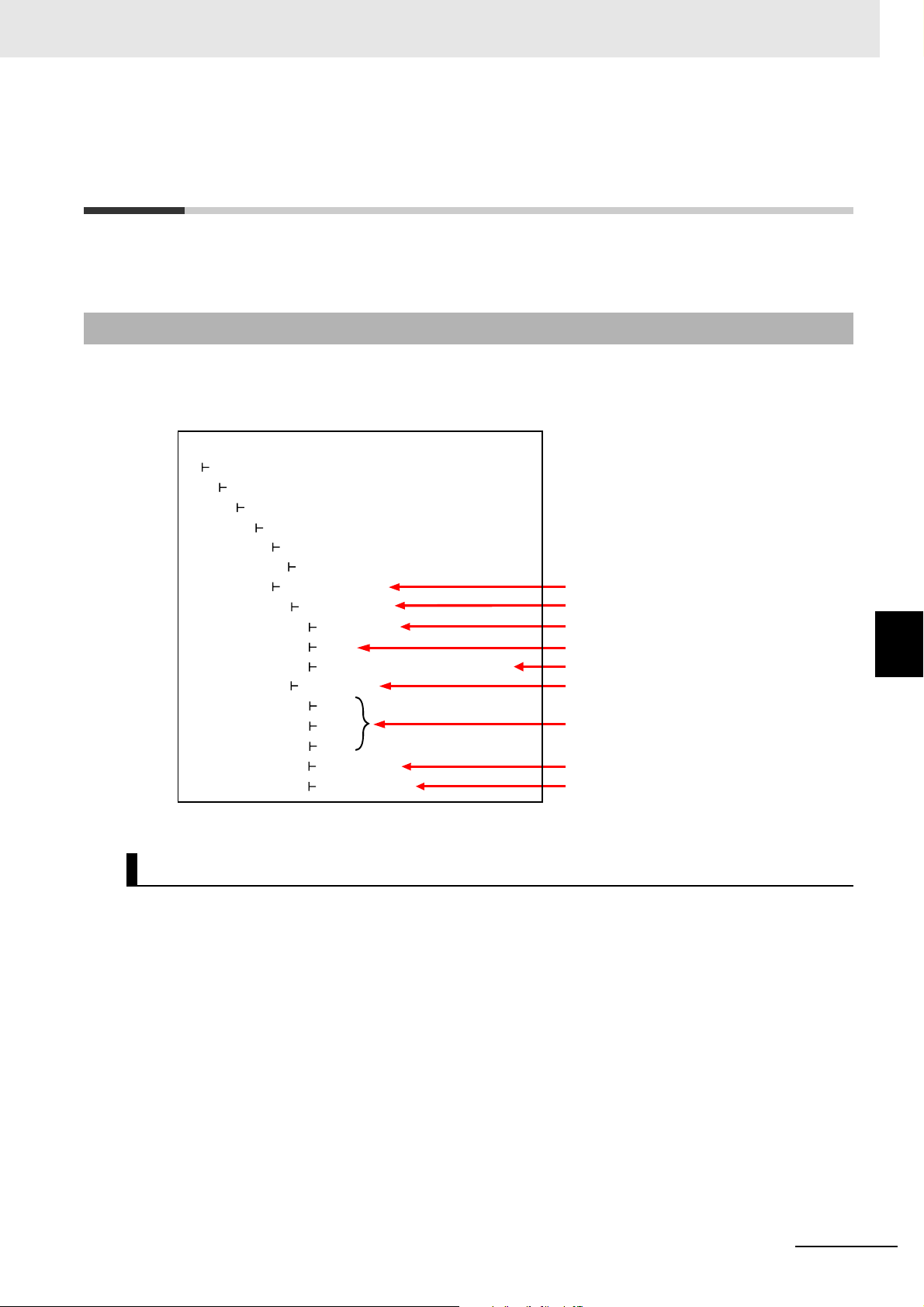
6 Connecting from the OPC UA Client and Reading/Writing Variables
Address space of the NJ/NX-series Controller that can be referenced by the client
Root
Objects
DeviceSet
SupportedTypes
Resources
ErrorStatus
Mode
GlobalVars
Var1
Var2
Var3
NumOfVars
NumOfValues
Controller name
Controller state
Each Published variable
Number of published variables
Published variables
Number of value attributes
of published variables
Error state of the Controller
Status of unpublished variables
Configuration
ContollerName
NxControllerType
DeviceStatus
Mode of the Controller
UnpublishedVariablesStatus
6-2 Reading/Writing Variables from the
OPC UA Client
This section describes the address space of the NJ/NX-series Controller visible to the OPC UA client,
and also reading/writing the variables of the CPU Unit from the OPC UA client.
6-2-1 Address Space of the NJ/NX-series Controller
The address space of the NJ/NX-series Controller is published as described below.
6-2 Reading/Writing Variables from the OPC UA Client
Controller Name
NJ/NX-series CPU Unit OPC UA User’s Manual (W588)
The Controller name set in the Sysmac Studio is displayed as the folder name.
6
6-2-1 Address Space of the NJ/NX-series Controller
6 - 3
Page 92

6 Connecting from the OPC UA Client and Reading/Writing Variables
Controller State
Properties Description Values
ErrorState Indicates the error state
of the Controller.
Mode Indicates the mode of
the Controller.
UnpublishedVariablesStatus Indicates the status of
unpublished variables
• NoError: Normal
• MajorFault: Major fault
• ContinuousError: Partial fault or minor fault
• RUN: RUN mode
• PROGRAM: PROGRAM mode
The following bits change to TRUE when a relevent
error occurs.
Bit 00: Number of Public Variables Exceeded
Bit 01: Number of Published Value Attributes Exceeded
Bit 02: The number of user-defined data types has been
exceeded
Bit 03: Variables of an unsupported data type exist
Bit 04 to bit 15: Reserved (The value is FALSE)
Number of Published Variables
The number of variables published under GlovalVars of the OPC UA Server is displayed. This will allow
you to check if the number of variables exceeds the upper limit.
The Controller state is displayed as shown below under DeviceState.
Number of Value Attributes of Published Variables
The number of value attributes in the OPC UA attribute of the variables published under GlovalVars of
the OPC UA Server is displayed. As a result, it is possible to check if the number of value attributes of
variables exceeds the upper limit.
6 - 4
NJ/NX-series CPU Unit OPC UA User’s Manual (W588)
Page 93
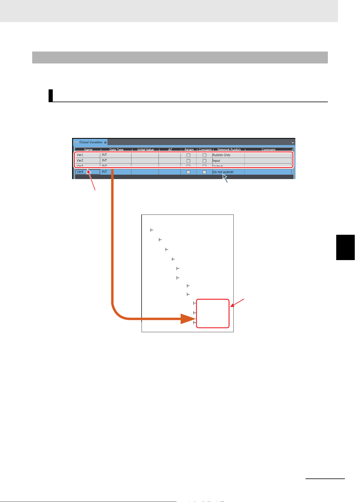
6 Connecting from the OPC UA Client and Reading/Writing Variables
Sysmac Studio
Root
Objects
DeviceSet
Configuration
ContollerName
Resources
SupportedTypes
GlobalVars
DeviceStatus
Var1
Var2
Var3
OPC UA client
Variables that are
published to OPC
UA client
Published variables
Variables that are not published to OPC UA client
6-2-2 Reading/Writing the Variables of the CPU Unit
With a read/write request from the OPC UA Client, global variables can be read from or written to the
CPU Unit via the target OPC UA Server.
Reading/writing the Global Variables of the CPU Unit
The OPC UA Server publishes only those global variables to the OPC UA client in which the network publish attribute is Publish Only, Output, or Input. Note that system-defined variables cannot be published.
6-2 Reading/Writing Variables from the OPC UA Client
NJ/NX-series CPU Unit OPC UA User’s Manual (W588)
6
6-2-2 Reading/Writing the Variables of the CPU Unit
6 - 5
Page 94

6 Connecting from the OPC UA Client and Reading/Writing Variables
Settings of Global Variable Attributes
Global variable
attribute
Setting of the variable on the OPC UA Server
Name Set to DisplayName and BrowseName.
Data type Refer to Data Type of Variables Published to the OPC UA Client on page 6-6.
Initial value ---
AT specification ---
Retained ---
Constant When this is set to ON, AccessLevel is set to Readable (Set to ReadOnly).
When this is set to OFF, AccessLevel is set to Readable, Writeable.
Network Publish Do not publish indicates that the variable is not published to the OPC UA client.
Publish Only, Output, and Input indicate that the variable is published to the OPC UA cli-
ent. Both reading and writing are possible.
However, even if registered as a network-published variable, there are restrictions on variables to be published to OPC UA clients. For details, refer to Restrictions on Publishing to
the OPC UA Client on page 6-8.
Comment ---
Data Type of Variables Published to the OPC UA Client
• Basic data type
The basic data types of the CPU Unit correspond to the OPC UA data types, as shown below.
Controller
Data type
BOOL Boolean Value indicating two states represented by an 8-bit value
SINT SByte 8-bit signed integer
USINT
BYTE
INT Int16 16-bit signed integer
UINT
WORD
DINT Int32 32-bit signed integer
UDINT
DWORD
LINT Int64 64-bit signed integer
ULINT
LWOR D
REAL Float IEEE-754 single-precision floating-point value
TIME
LREAL
STRING String UTF-8 string ending in NULL
DATE_AND_TIME
DATE
TIME_OF_DAY
OPC UA
Data type
Description of OPC UA data type
Byte 8-bit unsigned integer
UInt16 16-bit unsigned integer
UInt32 32-bit unsigned integer
UInt64 64-bit unsigned integer
Double IEEE-754 double-precision floating-point value
DateTime Date and time
64-bit data type. 100-ns time from January 01, 1601
6 - 6
Note Conforms to PLCopen OPC UA Information Model 1.00 Specifications.
NJ/NX-series CPU Unit OPC UA User’s Manual (W588)
Page 95

6 Connecting from the OPC UA Client and Reading/Writing Variables
Additional Information
Additional Information
GlobalVars
ArrayVar1
ArrayVar2
ArrayVar3
GlobalVars
StructVar1
StructVar2
StructVar3
•Array
As for the arrays of the CPU Unit, as shown below, an entire array variable is published as one node.
Example) ArrayVar1, ArrayVar2, and ArrayVar3 are array variables.
• Reading and writing between the OPC UA server and the OPC UA client is performed by the
entire array variable.
• Elements in the array can not be displayed, and reading/writing in element units is not supported.
• One-dimensional or multi-dimensional arrays can be specified.
•Structure
As for the structures of the CPU Unit, as shown below, an entire structure variable is published as
one node.
Example) StructVar1, StructVar2, and StructVar are structure data type variables
6-2 Reading/Writing Variables from the OPC UA Client
• Reading and writing between the OPC UA server and the OPC UA client is performed by the
entire structure variable.
• Publishing member hierarchies in the structure as one node and reading/writing in member units
are not supported.
If the OPC UA client has the functions to interpret the type information of the structure and to
display the member hierarchies in the structure, the member hierarchies in the structure can be
displayed.
• Enumerated type
The enumerated type of the CPU Unit is published as the Int32 type.
The enumerated type is handled as the DINT type in the CPU Unit.
If the OPC UA client has the functions to interpret the type information of the enumerated type
and to display it as the enumerated type, the enumerated type can be displayed.
6
6-2-2 Reading/Writing the Variables of the CPU Unit
NJ/NX-series CPU Unit OPC UA User’s Manual (W588)
6 - 7
Page 96

6 Connecting from the OPC UA Client and Reading/Writing Variables
Reading/Writing Variables from the OPC UA Client
The OPC UA client can perform reading/writing of the global variables of the CPU Unit serving as the
OPC UA Server.
Whether the OPC UA Client can read/write global variables depends on the setting value of the Net-
work Publish attribute, as shown below.
Setting value of Network Publish attribute of the
global variable
Do not publish Both reading and writing are impossible.
Publish Only, Input, or Output Both reading and writing are possible.
Reading/writing variables from the OPC UA client
Restrictions on Publishing to the OPC UA Client
Not all variables registered as network-published variables are published to the OPC UA client.
The variables published to the OPC UA client are restricted based on the following restrictions.
If there are variables that are not published to the OPC UA client, you need to review the network-published variables to make sure that they remain within the following limits.
6 - 8
NJ/NX-series CPU Unit OPC UA User’s Manual (W588)
Page 97

Restrictions
• Specify the number of definitions. Even if the same definition is used in multiple variables, the number of
definitions is not counted up.
• If the data type of the members of the structure is also a structure, the number of members (that are structures) is also counted.
• If the data type of the members of the structure is either basic data type or array, the members are not
counted.
6 Connecting from the OPC UA Client and Reading/Writing Variables
Scope of restriction Item Description
All network-published
variables
Number of public variables 10,000 max.
Number of value attributes
of public variables
*1
Number of structure defini-
10,000 max.
100 max.
6-2 Reading/Writing Variables from the OPC UA Client
tions that can be published
*2
Individual network-published variable
Size of public variable 1,024 bytes max.
Array specification • The maximum number of elements per variable is
1,024.
• Only elements whose element number starts with a
zero can be published.
Structure • The maximum number of members per structure type
variable *3 is 100.
• The maximum number of hierarchies is three.
• A multidimensional array specified structure *4 as well
as a structure containing a multidimensional array as a
The restrictions on public variables in the OPC UA Server are described below.
member
Unions • Cannot be published.
• A structure containing union(s) as member(s) cannot be
published.
*1. The number of value attributes is the sum total calculated as below:
Number of value attributes = (Number of basic data type variables) + (Number of array-specified elements) +
(Number of values in the structure)
*2. Details of Number of structure definitions that can be published are as follows:
*5
cannot be published.
6
6-2-2 Reading/Writing the Variables of the CPU Unit
*3. In the Number of members per structure type variable, if the data type of the members of the structure is also
a structure, the number of subordinate members (that are structures) is not counted as the restrictions are applied.
*4. The Multidimensional array specified structure indicates a multidimensional array in which the elements are
structures.
*5. The Structure containing a multidimensional array as a member indicates a structure containing (a) multidi-
mensional array as member(s).
A variable that is not published to the OPC UA Server due to the above restrictions is not displayed in
the OPC UA client even if it is registered as a network-published variable.
NJ/NX-series CPU Unit OPC UA User’s Manual (W588)
6 - 9
Page 98

6 Connecting from the OPC UA Client and Reading/Writing Variables
Method of Checking the CPU Unit
When an address space is prepared in the OPC UA Server of the CPU Unit, the above restrictions
are checked according to the procedures described below.
Step 1: The group of network-published variables is sorted in the ascending order of the character
code UTF-16 of the variable name.
For example, sorting is done in the order of single-byte numbers (in the order of 0 to 9) ->
single byte alphabets (in the order of A to Z) -> double-byte characters. Note that single-byte
alphanumeric characters are not case sensitive.
Step 2: Based on the list of the variables sorted by the variable name, check the variables first in
terms of the above restrictions set for all network-published variables, and then in terms of
the restrictions set for individual. If they remain within the above restrictions set for all network-published variables as well as the ones set for individual, the variables will be published to OPC UA clients.
Registering the Check Results
If, as a result of the above checks, variables that are not published to the OPC UA Server are found
to exist, the check results are registered in the event log and the Execution Log for each restriction.
• The occurrence information of the unpublished variables is registered in the event log.
• In addition to the occurrence information, detailed information of each published variable is also
registered in the Execution Log.
Execution Log
Item Event log
Number of public variables in all
network-published variables
Number of value attributes of
public variables in all network-published variables
Number of structure definitions
that can be published in all network-published variables
Size of public variables of each
network-published variable
Array specifications of each
network-published variable
Structures of each network-published variable
Unions of each network-published variable
Too Many Public Variables (Event code:
35D30000 hex)
Too Many Public Value
Attributes (Event code:
35D50000 hex)
Too Many Structure
Definitions (Event code:
35D60000 hex)
Unsupported Data Type
(Event code: 35D40000
hex)
(Category name - Log code (position of log
name))
• Occurrence information: SERVER-0100
(The maximum number of variables that
can be published has
been exceeded)
• Information about the
number of public variables: SERVER-0110
(Number of OPC UA
public variables)
• Occurrence information: SERVER-0101
(Variables containing
an unsupported data
type)
• Both the event log and the Execution Log are registered when any of the following operations is performed:
• When the power is turned ON or when the Controller is reset
• During a download
• During a restore operation
• When a variable added through online editing is subject to the restrictions.
For details on the event log and the Execution Log, refer to the NJ/NX-series Troubleshooting Manual
(Cat. No. W503)
and 7-1-5 Execution Log File Specifications on page 7-5, respectively.
Detailed information of
each published variable: SERVER-0111
(Detailed information of
OPC UA public variables)
6 - 10
NJ/NX-series CPU Unit OPC UA User’s Manual (W588)
Page 99

6 Connecting from the OPC UA Client and Reading/Writing Variables
Precautions for Safe Use
Method of Checking Variables Added through Online Editing
For a variable added through online editing from the Sysmac Studio, the above check operation is
performed for the added variable if any limit for all network-published variables has not been
reached yet. If the added variable does not exceed any limit, the variable is published to the OPC
UA client. If any limit item applied to all network published variables has been exceeded, the added
variable is not published.
Note that if multiple network-published variables are simultaneously added through online editing,
checking is performed according to the above sorting order only for the group of added variables
(re-checking of all variables is not performed).
Even if a global variable is set to Network Publish in the Sysmac Studio, the OPC UA client may
not be able to refer to or read/write the variable in some cases depending on the limits sets on
variables that can be published to the OPC UA client.
Refer to the event log or Execution Log, and review which variables to be published to the network depending on the cause of occurrence.
6-2 Reading/Writing Variables from the OPC UA Client
6
6-2-2 Reading/Writing the Variables of the CPU Unit
NJ/NX-series CPU Unit OPC UA User’s Manual (W588)
6 - 11
Page 100

6 Connecting from the OPC UA Client and Reading/Writing Variables
6 - 12
NJ/NX-series CPU Unit OPC UA User’s Manual (W588)
 Loading...