

Omron R88M-1 Series, NX1P2-1140DT, R88M-1M10030S, R88D-1SN01L-ECT, NX1P2-1040DT Startup Manual
...Page 1
Machine Automation Controller NJ/NX-series
Startup Guide
for Motion Control
NX1P2-
NX701-
NJ501-
NJ301-
NJ101-
SYSMAC-SE20
R88M-1
R88D-1SN-ECT
W514-E1-02
Page 2

NOTE
All rights reserved. No part of this publication may be reproduced, stored in a retrieval system, or transmitted, in
any form, or by any means, mechanical, electronic, photocopying, recording, or otherwise, without the prior
written permission of OMRON.
No patent liability is assumed with respect to the use of the information contained herein. Moreover, because
OMRON is constantly striving to improve its high-quality products, the information contained in this manual is
subject to change without notice. Every precaution has been taken in the preparation of this manual. Nevertheless, OMRON assumes no responsibility for errors or omissions. Neither is any liability assumed for damages
resulting from the use of the information contained in this publication.
Trademarks
• Sysmac and SYSMAC are trademarks or registered trademarks of OMRON Corporation in Japan and other
countries for OMRON factory automation products.
• Windows is either a registered trademark or a trademark of Microsoft Corporation in the United States and other
countries.
• EtherCAT
• Celeron, Intel, and Intel Core are trademarks of Intel Corporation or its subsidiaries in the U.S. and/or other
countries.
• Microsoft product screen shots reprinted with permission from Microsoft Corporation.
Other company names and product names in this document are the trademarks or registered trademarks of their
respective companies.
® is registered trademark and patented technology, licensed by Beckhoff Automation GmbH, Germany.
Page 3

Introduction
Thank you for purchasing an NJ/NX-series CPU Unit and the Sysmac Studio.
This NJ/NX-series Startup Guide for Motion Control (hereafter referred to as “this Guide”) describes the
startup procedures that are required to use the NJ/NX-series Motion Control Function Module for the
first time and provides operating instructions for the Sysmac Studio. You can follow the procedures that
are given in this Guide to set axis parameters and perform simple one-axis positioning and two-axis linear interpolation. This Guide does not contain safety information and other details that are required for
actual use of an NJ/NX-series Controller. Thoroughly read and understand the manuals for all of the
devices that are used in this Guide to ensure that the system is used safely. Review the entire contents
of these materials, including all safety precautions, precautions for safe use, and precautions for correct
use.
For the startup and operating instructions for NJ/NX-series CPU Units, refer to the NJ/NX-series Star-
tup Guide for CPU Units (Cat. No. W513).
Introduction
Intended Audience
This Guide is intended for the following personnel, who must also have knowledge of electrical systems
(an electrical engineer or the equivalent).
• Personnel in charge of introducing FA systems.
• Personnel in charge of designing FA systems.
• Personnel in charge of installing and maintaining FA systems.
Applicable Products
This Guide covers the following products.
• CPU Units of NJ/NX-series Machine Automation Controllers
• Sysmac Studio Automation Software
Special Information
The icons that are used in this Guide are described below.
Precautions for Safe Use
Precautions on what to do and what not to do to ensure safe usage of the product.
Precautions for Correct Use
Precautions on what to do and what not to do to ensure proper operation and performance.
Additional Information
Additional information to read as required.
This information is provided to increase understanding or make operation easier.
NJ/NX-series Startup Guide for Motion Control (W514)
1
Page 4

Terms and Conditions Agreement
Terms and Conditions Agreement
CPU Units of NJ/NX-series Machine Automation Controllers
Warranty, Limitations of Liability
Warranties
Exclusive Warranty
Omron’s exclusive warranty is that the Products will be free from defects in materials and workmanship for a period of twelve months from the date of sale by Omron (or such other period expressed in
writing by Omron). Omron disclaims all other warranties, express or implied.
Limitations
OMRON MAKES NO WARRANTY OR REPRESENTATION, EXPRESS OR IMPLIED, ABOUT
NON-INFRINGEMENT, MERCHANTABILITY OR FITNESS FOR A PARTICULAR PURPOSE OF
THE PRODUCTS. BUYER ACKNOWLEDGES THAT IT ALONE HAS DETERMINED THAT THE
PRODUCTS WILL SUITABLY MEET THE REQUIREMENTS OF THEIR INTENDED USE.
Omron further disclaims all warranties and responsibility of any type for claims or expenses based
on infringement by the Products or otherwise of any intellectual property right.
Buyer Remedy
Omron’s sole obligation hereunder shall be, at Omron’s election, to (i) replace (in the form originally
shipped with Buyer responsible for labor charges for removal or replacement thereof) the non-complying Product, (ii) repair the non-complying Product, or (iii) repay or credit Buyer an amount equal
to the purchase price of the non-complying Product; provided that in no event shall Omron be
responsible for warranty, repair, indemnity or any other claims or expenses regarding the Products
unless Omron’s analysis confirms that the Products were properly handled, stored, installed and
maintained and not subject to contamination, abuse, misuse or inappropriate modification. Return of
any Products by Buyer must be approved in writing by Omron before shipment. Omron Companies
shall not be liable for the suitability or unsuitability or the results from the use of Products in combination with any electrical or electronic components, circuits, system assemblies or any other materials or substances or environments. Any advice, recommendations or information given orally or in
writing, are not to be construed as an amendment or addition to the above warranty.
See http://www.omron.com/global/ or contact your Omron representative for published information.
Limitation on Liability; Etc
OMRON COMPANIES SHALL NOT BE LIABLE FOR SPECIAL, INDIRECT, INCIDENTAL, OR CONSEQUENTIAL DAMAGES, LOSS OF PROFITS OR PRODUCTION OR COMMERCIAL LOSS IN ANY
WAY CONNECTED WITH THE PRODUCTS, WHETHER SUCH CLAIM IS BASED IN CONTRACT,
WARRANTY, NEGLIGENCE OR STRICT LIABILITY.
Further, in no event shall liability of Omron Companies exceed the individual price of the Product on
which liability is asserted.
2
NJ/NX-series Startup Guide for Motion Control (W514)
Page 5

Application Considerations
Suitability of Use
Omron Companies shall not be responsible for conformity with any standards, codes or regulations
which apply to the combination of the Product in the Buyer’s application or use of the Product. At
Buyer’s request, Omron will provide applicable third party certification documents identifying ratings
and limitations of use which apply to the Product. This information by itself is not sufficient for a complete determination of the suitability of the Product in combination with the end product, machine, system, or other application or use. Buyer shall be solely responsible for determining appropriateness of
the particular Product with respect to Buyer’s application, product or system. Buyer shall take application responsibility in all cases.
NEVER USE THE PRODUCT FOR AN APPLICATION INVOLVING SERIOUS RISK TO LIFE OR
PROPERTY WITHOUT ENSURING THAT THE SYSTEM AS A WHOLE HAS BEEN DESIGNED TO
ADDRESS THE RISKS, AND THAT THE OMRON PRODUCT(S) IS PROPERLY RATED AND
INSTALLED FOR THE INTENDED USE WITHIN THE OVERALL EQUIPMENT OR SYSTEM.
Terms and Conditions Agreement
Programmable Products
Omron Companies shall not be responsible for the user’s programming of a programmable Product, or
any consequence thereof.
Disclaimers
Performance Data
Data presented in Omron Company websites, catalogs and other materials is provided as a guide for
the user in determining suitability and does not constitute a warranty. It may represent the result of
Omron’s test conditions, and the user must correlate it to actual application requirements. Actual performance is subject to the Omron’s Warranty and Limitations of Liability.
Change in Specifications
Product specifications and accessories may be changed at any time based on improvements and other
reasons. It is our practice to change part numbers when published ratings or features are changed, or
when significant construction changes are made. However, some specifications of the Product may be
changed without any notice. When in doubt, special part numbers may be assigned to fix or establish
key specifications for your application. Please consult with your Omron’s representative at any time to
confirm actual specifications of purchased Product.
Errors and Omissions
Information presented by Omron Companies has been checked and is believed to be accurate; however, no responsibility is assumed for clerical, typographical or proofreading errors or omissions.
NJ/NX-series Startup Guide for Motion Control (W514)
3
Page 6

Terms and Conditions Agreement
Sysmac Studio Automation Software
WARRANTY
• The warranty period for the Software is one year from the date of purchase, unless otherwise specifically agreed.
• If the User discovers defect of the Software (substantial non-conformity with the manual), and
return it to OMRON within the above warranty period, OMRON will replace the Software without
charge by offering media or download from OMRON’s website. And if the User discovers defect of
media which is attributable to OMRON and return it to OMRON within the above warranty period,
OMRON will replace defective media without charge. If OMRON is unable to replace defective
media or correct the Software, the liability of OMRON and the User’s remedy shall be limited to
the refund of the license fee paid to OMRON for the Software.
LIMITATION OF LIABILITY
• THE ABOVE WARRANTY SHALL CONSTITUTE THE USER’S SOLE AND EXCLUSIVE REMEDIES AGAINST OMRON AND THERE ARE NO OTHER WARRANTIES, EXPRESSED OR
IMPLIED, INCLUDING BUT NOT LIMITED TO, WARRANTY OF MERCHANTABILITY OR FITNESS FOR PARTICULAR PURPOSE. IN NO EVENT, OMRON WILL BE LIABLE FOR ANY
LOST PROFITS OR OTHER INDIRECT, INCIDENTAL, SPECIAL OR CONSEQUENTIAL DAMAGES ARISING OUT OF USE OF THE SOFTWARE.
• OMRON SHALL HAVE NO LIABILITY FOR DEFECT OF THE SOFTWARE BASED ON MODIFICATION OR ALTERNATION TO THE SOFTWARE BY THE USER OR ANY THIRD PARTY.
• OMRON SHALL HAVE NO LIABILITY FOR SOFTWARE DEVELOPED BY THE USER OR ANY
THIRD PARTY BASED ON THE SOFTWARE OR ANY CONSEQUENCE THEREOF.
APPLICABLE CONDITIONS
USER SHALL NOT USE THE SOFTWARE FOR THE PURPOSE THAT IS NOT PROVIDED IN
THE ATTACHED USER MANUAL.
CHANGE IN SPECIFICATION
The software specifications and accessories may be changed at any time based on improvements
and other reasons.
ERRORS AND OMISSIONS
The information in this manual has been carefully checked and is believed to be accurate; however,
no responsibility is assumed for clerical, typographical, or proofreading errors, or omissions.
4
NJ/NX-series Startup Guide for Motion Control (W514)
Page 7

Precautions
• When building a system, check the specifications for all devices and equipment that will make up the
system and make sure that the OMRON products are used well within their rated specifications and
performances. Safety measures, such as safety circuits, must be implemented in order to minimize
the risks in the event of a malfunction.
• Thoroughly read and understand the manuals for all devices and equipment that will make up the
system to ensure that the system is used safely. Review the entire contents of these materials,
including all safety precautions, precautions for safe use, and precautions for correct use.
• Confirm all regulations, standards, and restrictions that the equipment and devices in the system
must adhere to.
Software Licenses and Copyrights
This product incorporates certain third party software. The license and copyright information associated with this software is available at http://www.fa.omron.co.jp/nj_info_e/.
Precautions
NJ/NX-series Startup Guide for Motion Control (W514)
5
Page 8

Related Manuals
Related Manuals
The following manuals are related to the NJ/NX-series Controllers. Use these manuals for reference.
Manual name Cat. No. Model Application Meaning
NX-series NX1P2
CPU Unit Hardware User’s
Manual
NX-series
NX1P2 CPU Unit
Built-in I/O and Option Board
User's Manual
NX-series CPU Unit
Hardware User’s Manual
NJ-series CPU Unit Hardware
User’s Manual
NJ/NX-series CPU Unit Software User’s Manual
W578
W579
W535
W500
W501 NX701-
NX1P2-
NX1P2-
NX701-
NJ501-
NJ501-
NJ301-
NJ101-
NX1P2-
Learning the basic
Learning the basic
specifications of the
NX-series NX1P2
CPU Units, including
introductory information, designing, installation, and
maintenance.
Mainly hardware information is provided.
Learning about the
details of functions
only for an NX-series
NX1P2 CPU Unit and
an introduction of
functions for an
NJ/NX-series CPU
Unit.
Learning the basic
specifications of the
NX701 CPU Units,
including introductory
information, designing,
installation, and maintenance.
Mainly hardware information is provided.
specifications of the
NJ-series CPU Units,
including introductory information,
designing, installation, and maintenance.
Mainly hardware
information is provided.
Learning how to program and set up an
NJ/NX-series CPU
Unit.
Mainly software information is provided.
An introduction to the entire NX1P2 CPU Unit
system is provided along with the following
information on the NX1P2 CPU Unit.
• Features and system configuration
• Introduction
• Part names and functions
• General specifications
• Installation and wiring
• Maintenance and inspection
Of the functions for an NX1P2 CPU Unit, the
following information is provided.
• Built-in I/O
• Serial Communication Option Boards
• Analog I/O Option Boards
An introduction of following functions for an
NJ/NX-series CPU Unit is also provided.
• Motion control functions
• EtherNet/IP communications functions
• EtherCAT communications functions
An introduction to the entire NX701 system is
provided along with the following information on
the CPU Unit.
• Features and system configuration
• Introduction
• Part names and functions
• General specifications
• Installation and wiring
• Maintenance and inspection
Use this manual together with the NJ/NX-series
CPU Unit Software User’s Manual (Cat. No.
W501).
An introduction to the entire NJ-series system
is provided along with the following information
on a Controller built with an NJ501 CPU Unit.
• Features and system configuration
• Introduction
• Part names and functions
• General specifications
• Installation and wiring
• Maintenance and inspection
Use this manual together with the NJ/NX-series
CPU Unit Software User’s Manual (Cat. No.
W501).
The following information is provided on a Controller built with an NJ/NX-series CPU Unit.
• CPU Unit operation
• CPU Unit features
• Initial settings
• Programming based on IEC 61131-3 lan-
guage specifications
Use this manual together with the NJ-series
CPU Unit Hardware User’s Manual (Cat. No.
W500).
6
NJ/NX-series Startup Guide for Motion Control (W514)
Page 9

Manual name Cat. No. Model Application Meaning
NJ/NX-series CPU Unit Motion
Control User’s Manual
NJ/NX-series Instructions Reference Manual
NJ/NX-series Motion Control
Instructions Reference Manual
NJ/NX-series CPU Unit Builtin EtherCAT® Port U ser’s
Manual
NJ/NX-series Troubleshooting Manual
Sysmac Studio Version 1
Operation Manual
AC Servomotors/Servo Drives
1S-series with Built-in EtherCAT® Communications User’s
Manual
Servo System 1S-series
Startup Guide
W507 NX701-
NJ501-
NJ301-
NJ101-
NX1P2-
W502 NX701-
NJ501-
NJ301-
NJ101-
NX1P2-
W508 NX701-
W505 NX701-
W503 NX701-
W504
I586 R88M-1
I823 R88M-1L/-1M
NJ501-
NJ301-
NJ101-
NX1P2-
NJ501-
NJ301-
NJ101-
NX1P2-
NJ501-
NJ301-
NJ101-
NX1P2-
SYSMAC-SE2
R88D-1SN-ECT
(AC Servomotors)
R88D-1SN-ECT
(AC Servo Drives)
Learning about
motion control settings and programming concepts.
Learning detailed
specifications on the
basic instructions of
an NJ/NX-series CPU
Unit.
Learning about the
specifications of the
motion control
instructions.
Using the built-in
EtherCAT port on an
NJ/NX-series CPU
Unit.
Learning about the
errors that may be
detected in an
NJ/NX-series Controller.
Learning about the
operating procedures and functions
of the Sysmac Studio.
Learning how to use
the Servomotors/Servo Drives
with built-in EtherCAT
Communications.
Gaining a basic
understanding of a
1S-series AC Servomotors/Servo Drives.
The settings and operation of the CPU Unit and
programming concepts for motion control are
described.
When programming, use this manual together
with the NJ/NX-series CPU Unit Hardware
User’s Manual (Cat. No. W500) and NJ/NX-
series CPU Unit Software User’s Manual (Cat.
No. W501).
The instructions in the instruction set (IEC
61131-3 specifications) are described.
When programming, use this manual together
with the NJ/NX-series CPU Unit Hardware
User’s Manual (Cat. No. W500) and NJ/NX-
series CPU Unit Software User’s Manual (Cat.
No. W501).
The motion control instructions are described.
When programming, use this manual together
with the NJ/NX-series CPU Unit Hardware
User’s Manual (Cat. No. W500), NJ/NX-series
CPU Unit Software User’s Manual (Cat. No.
W501) and NJ/NX-series CPU Unit Motion Control User’s Manual (Cat. No. W507).
Information on the built-in EtherCAT port is provided.
This manual provides an introduction and provides information on the configuration, features,
and setup.
Use this manual together with the NJ/NX-series
CPU Unit Hardware User’s Manual (Cat. No.
W500) and NJ/NX-series CPU Unit Software
User’s Manual (Cat. No. W501).
Concepts on managing errors that may be
detected in an NJ/NX-series Controller and
information on individual errors are described.
Use this manual together with the NJ/NX-series
CPU Unit Hardware User’s Manual (Cat. No.
W500) and NJ/NX-series CPU Unit Software
User’s Manual (Cat. No. W501).
The operating procedures of the Sysmac Studio are described.
Describes the hardware, setup methods and
functions of the Servomotors/Servo Drives with
built-in EtherCAT Communications.
Describes the procedures for installation and
setup of a 1S-series AC Servo Drive.
Related Manuals
NJ/NX-series Startup Guide for Motion Control (W514)
7
Page 10

Revision History
W514-E1-02
Cat. No.
Revision code
Revision History
A manual revision code appears as a suffix to the catalog number on the front and back covers of the
manual.
Revision
code
01 November 2011 Original production
02 February 2017 Made changes accompanying the addition of NX1P2 CPU Units and
Date Revised content
1S-series AC Servomotors / Servo Drivers
8
NJ/NX-series Startup Guide for Motion Control (W514)
Page 11

Revision History
NJ/NX-series Startup Guide for Motion Control (W514)
9
Page 12

CONTENTS
CONTENTS
Introduction ...............................................................................................................1
Intended Audience ...................................................................................................................................... 1
Applicable Products .................................................................................................................................... 1
Special Information ..................................................................................................................................... 1
Terms and Conditions Agreement...........................................................................2
CPU Units of NJ/NX-series Machine Automation Controllers ..................................................................... 2
Warranty, Limitations of Liability ................................................................................................................. 2
Application Considerations ......................................................................................................................... 3
Disclaimers ................................................................................................................................................. 3
Sysmac Studio Automation Software ......................................................................................................... 4
Precautions................................................................................................................5
Software Licenses and Copyrights ............................................................................................................. 5
Related Manuals........................................................................................................6
Revision History........................................................................................................8
Section 1 Features and System Configuration of NJ/NX-series
Controllers and 1S-series AC Servo Systems
1-1 Features of NJ/NX Series and 1S Series ............................................................................... 1-2
1-2 System Configuration and Configuration Devices............................................................... 1-4
1-2-1 Devices Used in This Guide........................................................................................................ 1-4
1-2-2 Configuration of the System Constructed in This Guide .............................................................1-5
Section 2 Before You Begin
2-1 Installing the Sysmac Studio.................................................................................................. 2-2
2-2 Wiring the Devices................................................................................................................... 2-3
2-2-1 Wiring the NX1P CPU Unit Power Supply...................................................................................2-3
2-2-2 Wiring the Servo Drive Power Supply ......................................................................................... 2-3
2-2-3 Laying EtherCAT Communications Cables ................................................................................. 2-4
2-2-4 Wiring the Servo Drives and the Servomotors ............................................................................ 2-5
2-2-5 Wiring the Control Input Signals for the Servo Drives.................................................................2-6
Section 3 Setting Up a Single-axis Servo System
3-1 Single-axis Servo System Operation ..................................................................................... 3-2
3-2 System Setup Procedures ......................................................................................................3-3
3-3 Creating a Project .................................................................................................................... 3-4
3-4 Creating the EtherCAT Network Configuration..................................................................... 3-7
10
3-5 Programming ........................................................................................................................... 3-9
3-5-1 Setting the Axis ...........................................................................................................................3-9
3-5-2 Creating the Program................................................................................................................3-17
3-5-3 Checking the Program .............................................................................................................. 3-27
3-6 Transferring the Project to the CPU Unit ............................................................................. 3-28
NJ/NX-series Startup Guide for Motion Control (W514)
Page 13

CONTENTS
3-7 Confirming System Operation.............................................................................................. 3-32
3-7-1 Checking for Controller Errors .................................................................................................. 3-32
3-7-2 Resetting the Absolute Encoder from the Sysmac Studio ........................................................ 3-35
3-7-3 Checking the Servo Drive Wiring.............................................................................................. 3-38
3-7-4 Checking Program Operation ................................................................................................... 3-44
3-7-5 Using Data Tracing to Check Operation ................................................................................... 3-50
Section 4 Two-axis Linear Interpolation Program
4-1 Two-axis Servo System Operation......................................................................................... 4-2
4-2 System Setup Procedures ......................................................................................................4-3
4-3 Changing the Program............................................................................................................ 4-4
4-3-1 Setting Axis 0 to a Motion Control Axis....................................................................................... 4-4
4-3-2 Adding a Servo Drive to the EtherCAT Network Configuration................................................... 4-5
4-3-3 Adding Axis 1 and Setting an Axes Group.................................................................................. 4-7
4-3-4 Adding Instructions and Checking the Program ....................................................................... 4-15
4-3-5 Transferring the Project to the CPU Unit...................................................................................4-21
4-4 Confirming System Operation.............................................................................................. 4-22
4-4-1 Checking the New Axis 1.......................................................................................................... 4-22
4-4-2 Checking Program Operation ................................................................................................... 4-22
4-4-3 Using Data Tracing to Check Operation ................................................................................... 4-29
Appendices
A-1 Settings When Control Input Signals Are Not Wired ...........................................................A-2
A-2 Using the 3D Motion Trace Display Mode to Check Operation ...........................................A-7
NJ/NX-series Startup Guide for Motion Control (W514)
11
Page 14

12
CONTENTS
NJ/NX-series Startup Guide for Motion Control (W514)
Page 15

1
Features and System Configuration of NJ/NX-series
Controllers and 1S-series AC Servo Systems
This section describes the configuration of the Servo system that is constructed in this
Guide and the products that make up that system.
1-1 Features of NJ/NX Series and 1S Series . . . . . . . . . . . . . . . . . . . . . . . . . . . 1-2
1-2 System Configuration and Configuration Devices . . . . . . . . . . . . . . . . . . . 1-4
1-2-1 Devices Used in This Guide . . . . . . . . . . . . . . . . . . . . . . . . . . . . . . . 1-4
1-2-2 Configuration of the System Constructed in This Guide . . . . . . . 1-5
NJ/NX-series Startup Guide for Motion Control (W514)
1-1
Page 16

1 Features and System Configuration of NJ/NX-series Controllers and 1S-series AC Servo
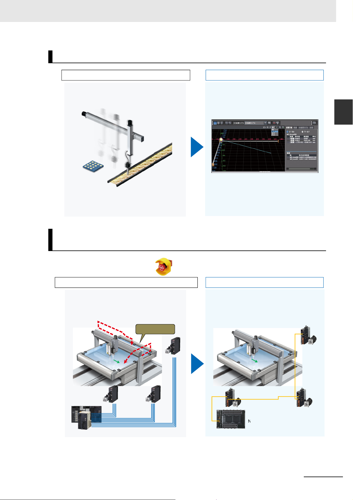
Required substantial time for wiring work.
Any wiring errors also required time to check.
Only one cable: easy connections and no mistakes!
Many cables, high
cost, complicated
ordering, and
many maintenance
materials.
External wiring used
screw-type terminal
blocks, requiring labor
for screw tightening and
periodic re-tightening.
Only one EtherCAT
cable.
Push-in terminal block makes
connections of Servo systems easy.
No need for a relay terminal block.
40
J
6
-
2B
CJ1W
-
21
3/
NC4
13
4
0J6
-
2B
C
J
1
W
-
21
3
/
NC4
13
Traditional System Using Position Control Units
External
wiring
External
wiring
NX1P and 1S Series
Three software were used for Position Control Unit
settings, ladder programming, and Servo System
settings respectively. You had to create a program while
monitoring and tuning the settings.
The Sysmac Studio, which integrates ladder programming, motion, and configuration, facilitates positioning
control. Simple monitoring and modification!
Servo power ON
Relative
positioning
Distance
Velocity
Acceleration
Deceleration
Ladder + motion
Servo System
Traditional System Using Position Control Units
NX1P and 1S Series
CPU Unit Position Control Unit
User programUser program
NC processorNC processorNC processor
User program
Parameter
Settings
Pulse
output
PLC bus
1-1 Features of NJ/NX Series and 1S Series
The NX/NJ-series Machine Automation Controllers provide advanced motion control previously executed by dedicated controllers or Special Units.
The CPU Units have a built-in EtherCAT port for real-time machine control.
Easy Wiring
Easy Motion Programming
1-2
NJ/NX-series Startup Guide for Motion Control (W514)
Page 17
1 Features and System Configuration of NJ/NX-series Controllers and 1S-series AC Servo
The actual equipment was required to check operation
during debugging.
You can check 3D operation at your desk, shortening
on-site debugging time. While viewing the programmed
Servomotor path, you can review operation with the
machine engineers prior to system completion and fix
problems in advance!
Traditional System Using Position Control Units
NX1P and 1S Series
N
1-1 Features of NJ/NX Series
3D Simulation Makes Debugging Easy
and 1S Series
1
Fast Recovery after Power Interruptions with the Standard-feature
Absolute Encoder
After an emergency stop
or power interruption
Traditional Servo System Using Incremental Encoder
Homing operation was required to resume positioning
because home information was cleared.
NX1P and 1S Series
Introducing an absolute encoder to the 1S-series
Servomotor eliminates the need for homing operation,
so you can resume positioning immediately. The
battery-free encoder retains the absolute positions. No
battery, no maintenance!
Homing
1S
1S
1S
NX1P
NJ/NX-series Startup Guide for Motion Control (W514)
1-3
Page 18
1 Features and System Configuration of NJ/NX-series Controllers and 1S-series AC Servo
1-2 System Configuration and Configuration Devices
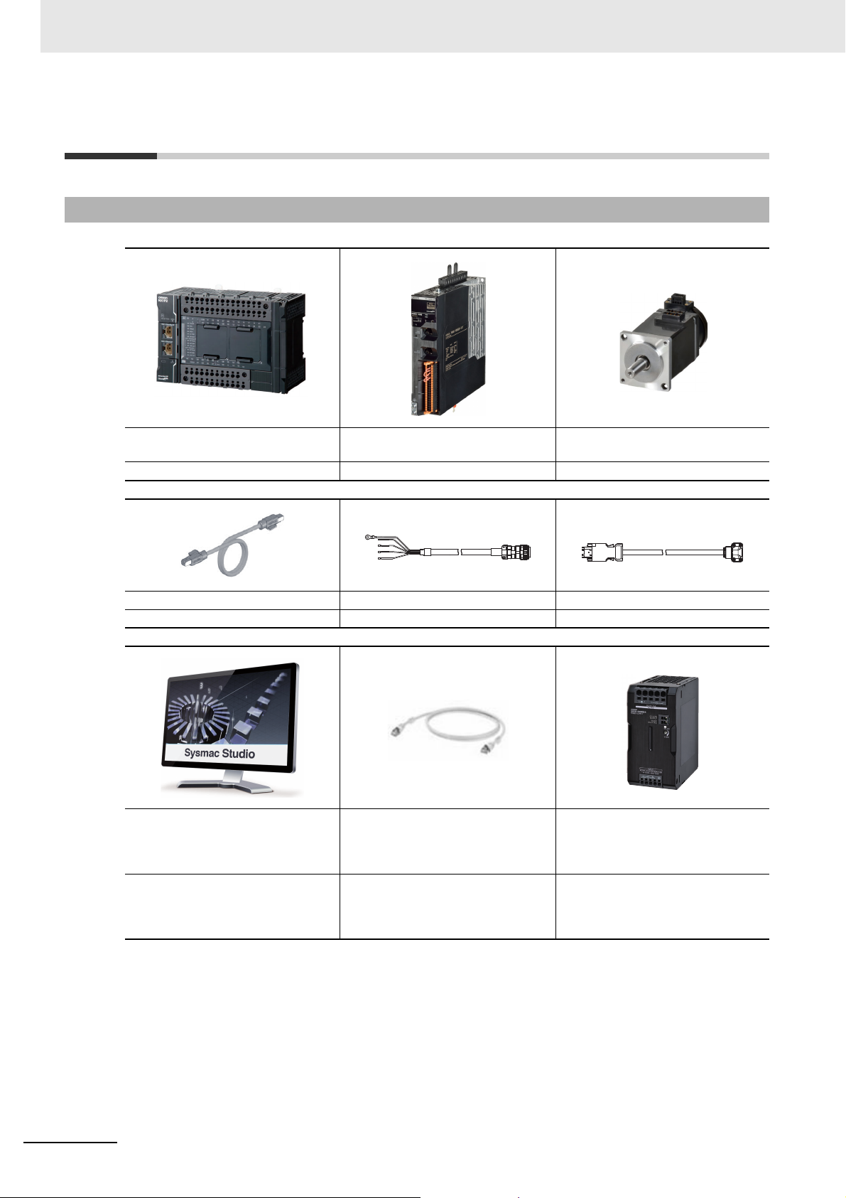
1-2-1 Devices Used in This Guide
NX1P
Machine Automation Controller
1S-series AC Servo Drive 1S-series AC Servomotor
NX1P2-1140DT R88D-1SN01L-ECT R88M-1M10030S
EtherCAT Communications Cable Motor Power Cable Encoder Cable
XS5W-T421-MD-K R88A-CA1A003S R88A-CR1A003C
Sysmac Studio
Automation Software
Standard Edition
Ethernet Cable
(100BASE-TX/10BASE-T)
24 VDC Power Supply
Version 1.17 or higher
SYSMAC-SE200D
(Media only)
SYSMAC-SE201L
--- Example: S8VK-S
(One license)
1-4
NJ/NX-series Startup Guide for Motion Control (W514)
Page 19
1 Features and System Configuration of NJ/NX-series Controllers and 1S-series AC Servo
RUN
E
R
R
I
N
L
/
A
R
88
D-1
S
N
L
/
A
FS
OU
T
E
th
e
r
CA
T
RUN
E
R
R
I
N
L
/
A
R88
D-1
S
N
L
/
A
FS
OU
T
E
th
e
r
CA
T
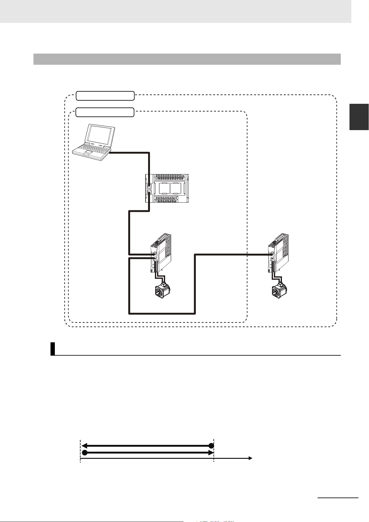
Sysmac Studio
Ethernet Cable
Two-axis Servo System
Single-axis Servo System
NX1P2-1140DT
CPU Unit
R88D-1SN01L-ECT Servo Drive (1st Drive)
Node Address 1 (Axis 0)
R88M-1M10030S
Servomotor
R88D-1SN01L-ECT Servo Drive
(2nd Drive)
Node Address 2
(Axis 1)
R88M-1M10030S Servomotor
EtherCAT communications cables
Section 4 Two-axis Linear Interpolation Program
Section 3 Setting Up a Single-axis Servo System
1-2-2 Configuration of the System Constructed in This Guide
This NJ/NX-series Startup Guide for Motion Control (hereafter referred to as "this Guide") builds the
Servo system in the following two steps.
1-2 System Configuration and
Configuration Devices
1
1-2-2 Configuration of the System Constructed in This Guide
Single-axis Servo System
This system performs single-axis positioning using a Servo Drive and Servomotor for one axis. The
steps from device wiring to software design and debugging are described.
Device connections are described in Section 2 Before You Begin, and software design and debugging
are described in Section 3 Setting Up a Single-axis Servo System.
Positioning example:
Single-axis positioning
Velocity : 10.000 mm/s
Acceleration rate : 200.000 mm/s
Deceleration rate : 200.000 mm/s
Axis 0
2
2
0.000 mm 20.000 mm
NJ/NX-series Startup Guide for Motion Control (W514)
1-5
Page 20
1 Features and System Configuration of NJ/NX-series Controllers and 1S-series AC Servo
Axis 0
800.000 mm X
600.000 mm
Linear 2
Linear 1
Y
0.000 mm
0.000 mm
Axis 1
Interpolation velocity : 200.000 mm/s
Acceleration rate : 400.000 mm/s
2
Deceleration rate : 400.000 mm/s
2
Two-axis Servo System
This system performs linear interpolation using Servo Drives and Servomotors for two axes. The steps
from device wiring to software design and debugging are described.
Device connections are described in Section 2 Before You Begin, and software design and debugging
are described in Section 4 Two-axis Linear Interpolation Program.
The NX1P2-9024DT/-9024DT1 cannot be used in this linear interpolation example.
Use the NX1P2-1040DT/-1040DT1, NX1P2-1140DT/-1140DT1, NJ-series CPU Unit, or NX7 CPU Unit.
Positioning example:
1-6
NJ/NX-series Startup Guide for Motion Control (W514)
Page 21

Before You Begin
This section describes the installation of the Sysmac Studio and the process of assembling and wiring the hardware.
2-1 Installing the Sysmac Studio . . . . . . . . . . . . . . . . . . . . . . . . . . . . . . . . . . . . 2-2
2-2 Wiring the Devices . . . . . . . . . . . . . . . . . . . . . . . . . . . . . . . . . . . . . . . . . . . . . 2-3
2-2-1 Wiring the NX1P CPU Unit Power Supply . . . . . . . . . . . . . . . . . . . . . . . . . . . . 2-3
2-2-2 Wiring the Servo Drive Power Supply . . . . . . . . . . . . . . . . . . . . . . . . . . . . . . . 2-3
2-2-3 Laying EtherCAT Communications Cables . . . . . . . . . . . . . . . . . . . . . . . . . . . 2-4
2-2-4 Wiring the Servo Drives and the Servomotors . . . . . . . . . . . . . . . . . . . . . . . . . 2-5
2-2-5 Wiring the Control Input Signals for the Servo Drives . . . . . . . . . . . . . . . . . . . 2-6
2
NJ/NX-series Startup Guide for Motion Control (W514)
2-1
Page 22

2 Before You Begin
Additional Information
Precautions for Correct UsePrecautions for Correct Use
2-1 Installing the Sysmac Studio
The Sysmac Studio is the Support Software that you use for an NJ/NX-series Controller. On it, you can
create the Controller configuration and settings, you can write the programs, and you can debug and
simulate operation.
Use the following procedure to install the Sysmac Studio.
1
Set the Sysmac Studio installation disk into the DVD-ROM drive.
The setup program is started automatically and the Select Setup Language Dialog Box is displayed.
2
Select the language to use, and then click the OK Button.
The Sysmac Studio Setup Wizard is started.
3
Follow the instructions given by the Setup Wizard to complete the installation.
4
Restart the computer when the installation is completed.
• The system requirements for the Sysmac Studio are given in the following table.
OS CPU RAM Display
Windows 7
(32-bit or 64-bit edition)
Windows 8
(32-bit or 64-bit edition)
Windows 8.1
(32-bit or 64-bit edition)
Windows 10
(32-bit or 64-bit edition)
• Refer to the Sysmac Studio Version 1 Operation Manual (Cat. No. W504) if you are unable to
install the Sysmac Studio with the above instructions.
If CX-One version 4 or lower is installed, the installation is cancelled and the Sysmac Studio cannot be installed. In that case, uninstall the CX-One before you install the Sysmac Studio.
Minimum
Recommended
IBM AT or compatible with
®
Celeron® processor
Intel
540 (1.8 GHz)
IBM AT or compatible with
®
CoreTM i5 M520 pro-
Intel
cessor (2.4 GHz) or the
equivalent
2 GB XGA 1,024 768,
16 million colors
4 GB
min.
WXGA 1,280 800,
16 million colors
2-2
NJ/NX-series Startup Guide for Motion Control (W514)
Page 23
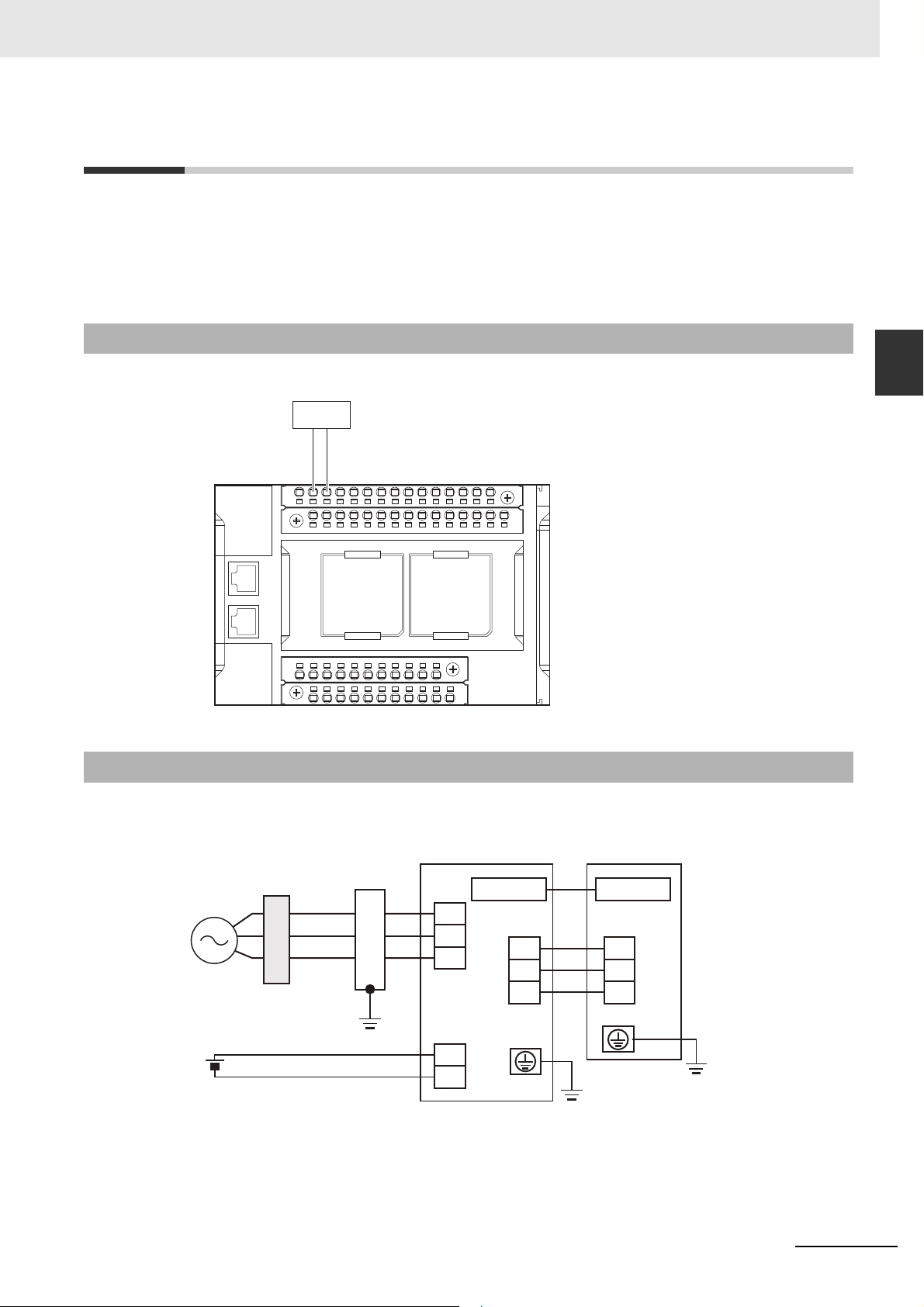
2-2 Wiring the Devices
24 VDC
+ −
Servo Drive
Protection
element
Noise filter
Servomotor
U
V
W
EncoderEncoder
L1
L2
L3
24V
0V
U
V
W
This section describes how to wire the assembled the hardware devices.
This section gives an overview of the wiring procedures. Refer to the manuals for the devices that are
used in the system for detailed wiring procedures and safety precautions.
2-2-1 Wiring the NX1P CPU Unit Power Supply
Wire the CPU Unit to the DC power supply.
2 Before You Begin
2-2 Wiring the Devices
2
2-2-1 Wiring the NX1P CPU Unit Power Supply
2-2-2 Wiring the Servo Drive Power Supply
Wire the Servo Drives to the power supply as shown in the following figure.
NJ/NX-series Startup Guide for Motion Control (W514)
2-3
Page 24
2 Before You Begin
RUN INOUT
FS
L/A L/A
ERR
RUN INOUT
FS
L/A L/A
ERR
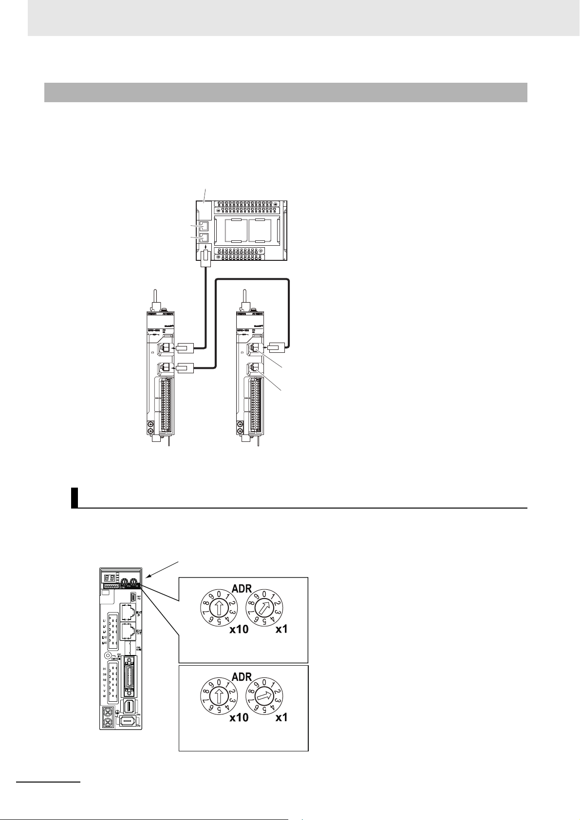
Built-in EtherCAT port
Built-in EtherNet/IP port
NX-series NX1P2 CPU Unit
First Servo Drive
Second Servo Drive
Connector IN port for
EtherCAT communications
Connector OUT port for
EtherCAT communications
2-2-3 Laying EtherCAT Communications Cables
Connect the EtherCAT slave communications cables between the built-in EtherCAT port on the CPU
Unit and the EtherCAT slaves as shown in the following figure.
Connect the communications cable from the built-in EtherCAT port to the input port on the first slave,
and then connect the communications cable to the next slave to the output port on the first slave.
Do not connect anything to the output port of the slave at the end of the network.
Setting the Node Addresses of the Servo Drives
Set the node addresses of the Servo Drives as shown below.
Only the first Servo Drive is used in Section 3 Setting Up a Single-axis Servo System.
The second Servo Drive is added in Section 4 Two-axis Linear Interpolation Program.
Rotary switches for setting
ADR
the node address
10s digit
Set to 0. Set to 1.
10s digit
Set to 0. Set to 2.
First Servo Drive
1s digit
Second Servo Drive
1s digit
2-4
NJ/NX-series Startup Guide for Motion Control (W514)
Page 25
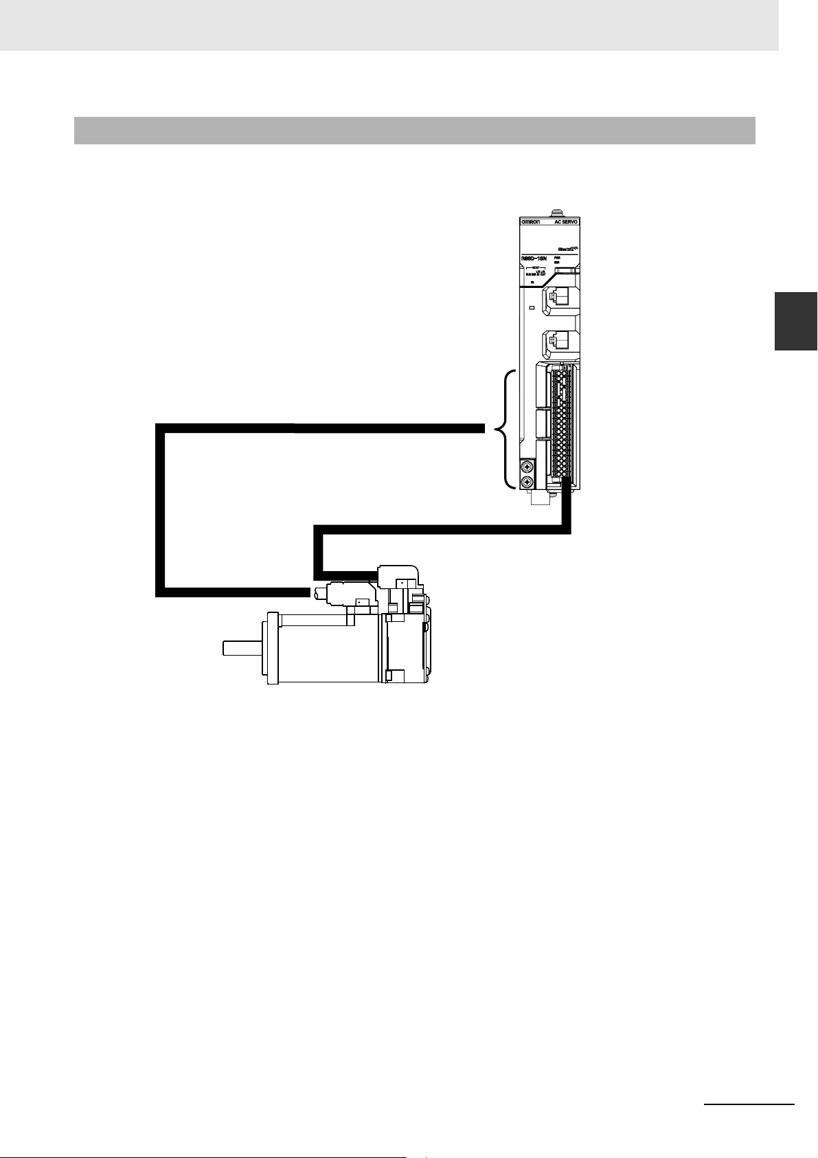
2-2-4 Wiring the Servo Drives and the Servomotors
Motor Power Cable
R88A-CA1A003S
Servomotor
Encoder Cable
R88A-CR1A003C
Servo Drive
2 Before You Begin
Wire the Servo Drives and the Servomotors as shown in the following figure.
2-2 Wiring the Devices
2
2-2-4 Wiring the Servo Drives and the Servomotors
NJ/NX-series Startup Guide for Motion Control (W514)
2-5
Page 26
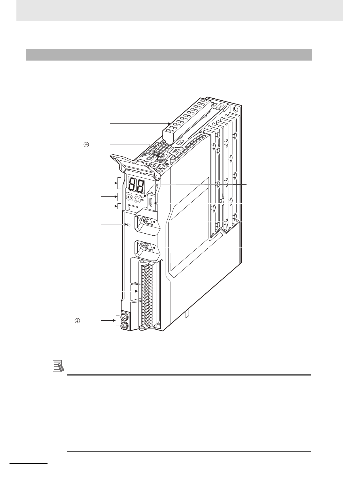
2 Before You Begin
Additional Information
CN7
ID
x1
x16
0
1
2
3
4
5
6
7
8
9
A
B
C
D
E
F
9
A
B
C
0
1
2
3
4
5
6
7
8
9
A
B
C
D
E
F
9
A
B
C
Main circuit connector (CNA)
terminal
7-segment LED display
ID switches
Status indicators
Charge lamp
Control I/O connector
(CN1)*1
terminal
Status indicators
USB connector (CN7)
EtherCAT communications
connector
(ECAT IN CN10)
EtherCAT communications
connector
(ECAT OUT CN11)
2-2-5 Wiring the Control Input Signals for the Servo Drives
Wire the control input signals for the Servo Drive using the R88A-CN101C Control I/O connector (CN1).
For details on wiring, refer to the AC Servomotors/Servo Drives 1S-series with Built-in EtherCAT Com-
munications User's Manual (Cat. No. I586).
*1 Control I/O Connector (CN1):
Used for command input signals, I/O signals, and as the safety device connector. The short-circuit wire is
installed on the safety signals before shipment.
• If you use the default Servo parameters, you must wire the immediate stop input, negative
drive prohibit input, and the positive drive prohibit input.
If these inputs are not wired, the CPU Unit will remain in the drive prohibit signal and emergency stop signal detected state, and a minor fault level Controller error will occur. The minor
fault level Controller errors that will occur are an Immediate Stop Input Error and a Drive Prohibition Input Error. (The event codes are 68220000 and 64E30000.)
• If the above signals are temporarily not wired while commissioning the system, you can temporarily change the Servo parameters to prevent these errors from occurring in the CPU Unit.
Refer to A-1 Settings When Control Input Signals Are Not Wired for details on the settings that
you must change in this case.
2-6
NJ/NX-series Startup Guide for Motion Control (W514)
Page 27

Setting Up a Single-axis Servo
System
This section describes the procedures and operations required to set up a Servo system for one axis.
3-1 Single-axis Servo System Operation . . . . . . . . . . . . . . . . . . . . . . . . . . . . . . 3-2
3-2 System Setup Procedures . . . . . . . . . . . . . . . . . . . . . . . . . . . . . . . . . . . . . . . 3-3
3-3 Creating a Project . . . . . . . . . . . . . . . . . . . . . . . . . . . . . . . . . . . . . . . . . . . . . 3-4
3-4 Creating the EtherCAT Network Configuration . . . . . . . . . . . . . . . . . . . . . . 3-7
3-5 Programming . . . . . . . . . . . . . . . . . . . . . . . . . . . . . . . . . . . . . . . . . . . . . . . . . 3-9
3-5-1 Setting the Axis . . . . . . . . . . . . . . . . . . . . . . . . . . . . . . . . . . . . . . . . . . . . . . . . 3-9
3-5-2 Creating the Program . . . . . . . . . . . . . . . . . . . . . . . . . . . . . . . . . . . . . . . . . . 3-17
3-5-3 Checking the Program . . . . . . . . . . . . . . . . . . . . . . . . . . . . . . . . . . . . . . . . . . 3-27
3-6 Transferring the Project to the CPU Unit . . . . . . . . . . . . . . . . . . . . . . . . . . 3-28
3-7 Confirming System Operation . . . . . . . . . . . . . . . . . . . . . . . . . . . . . . . . . . 3-32
3-7-1 Checking for Controller Errors . . . . . . . . . . . . . . . . . . . . . . . . . . . . . . . . . . . . 3-32
3-7-2 Resetting the Absolute Encoder from the Sysmac Studio . . . . . . . . . . . . . . . 3-35
3-7-3 Checking the Servo Drive Wiring . . . . . . . . . . . . . . . . . . . . . . . . . . . . . . . . . . 3-38
3-7-4 Checking Program Operation . . . . . . . . . . . . . . . . . . . . . . . . . . . . . . . . . . . . 3-44
3-7-5 Using Data Tracing to Check Operation . . . . . . . . . . . . . . . . . . . . . . . . . . . . . 3-50
3
NJ/NX-series Startup Guide for Motion Control (W514)
3-1
Page 28
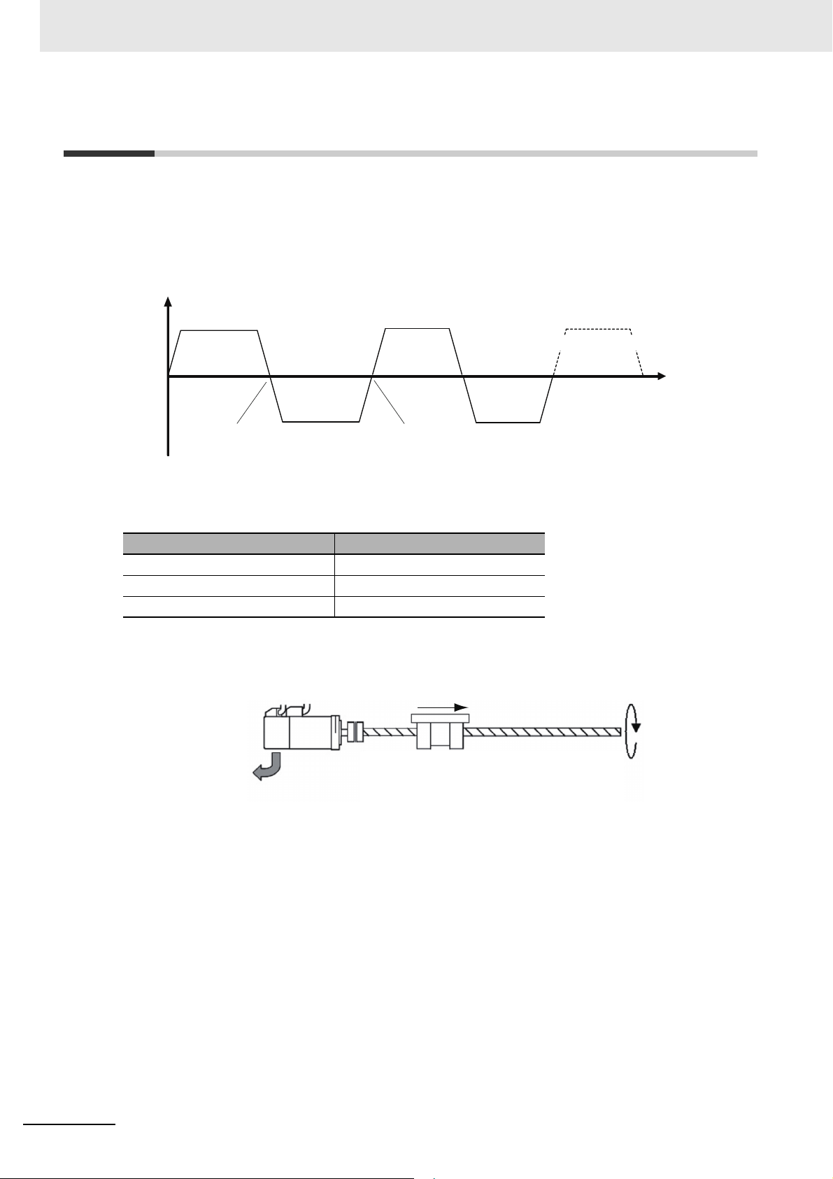
3 Setting Up a Single-axis Servo System
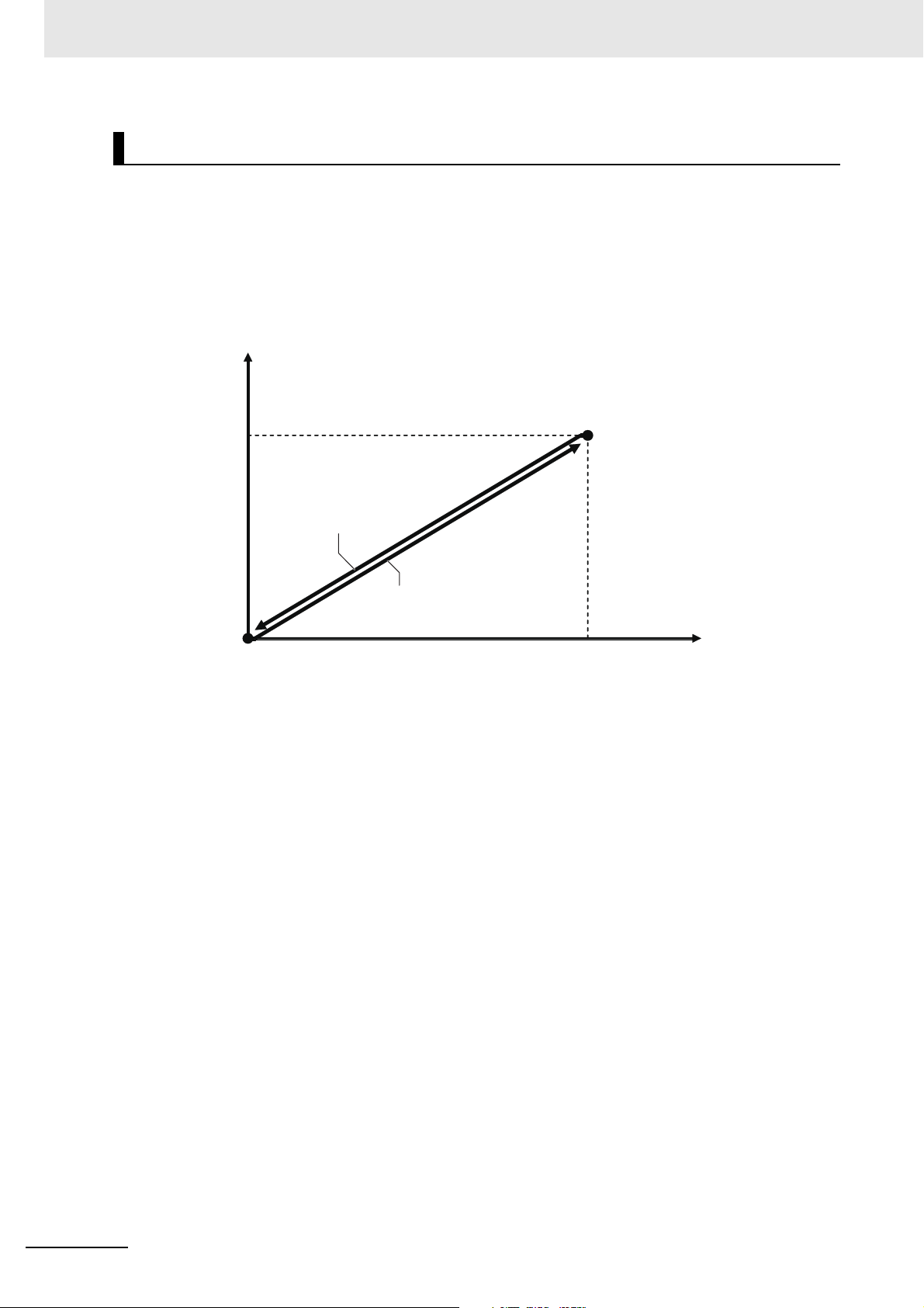
Velocity
Position after traveling
in the positive direction
Position after traveling
in the negative direction
Operation of Axis 0 (Node Address 1)
The operation is repeated.
Time
Positive direction
Negative direction
Travel distance: −20.000 mm
Speed: 10.000 mm/s
Acceleration rate: 200.000 mm/s
2
Deceleration rate: 200.000 mm/s
2
Travel distance: 20.000 mm
Speed: 10.000 mm/s
Acceleration rate: 200.000 mm/s
2
Deceleration rate: 200.000 mm/s
2
3-1 Single-axis Servo System Operation
This section describes the operation of the single-axis Servo system that is set up in this Guide.
Axis 0 performs alternating single-axis positioning in the positive and negative directions.
The mechanical configuration of axis 0 is as shown in the following table.
Item Axis 0 mechanical configuration
Motor rated speed 3,000 r/min
Ball screw pitch 10.000 mm
Encoder resolution 23 bits/rotation
Servomotor
Encoder resolution: 23 bits/rotation
Rated speed: 3,000 r/min
Command pulse count per motor rotation
23 bits = 8,388,608
10 mm
Ball screw
Ball screw pitch: 10 mm
1 rotation
3-2
NJ/NX-series Startup Guide for Motion Control (W514)
Page 29
3 Setting Up a Single-axis Servo System
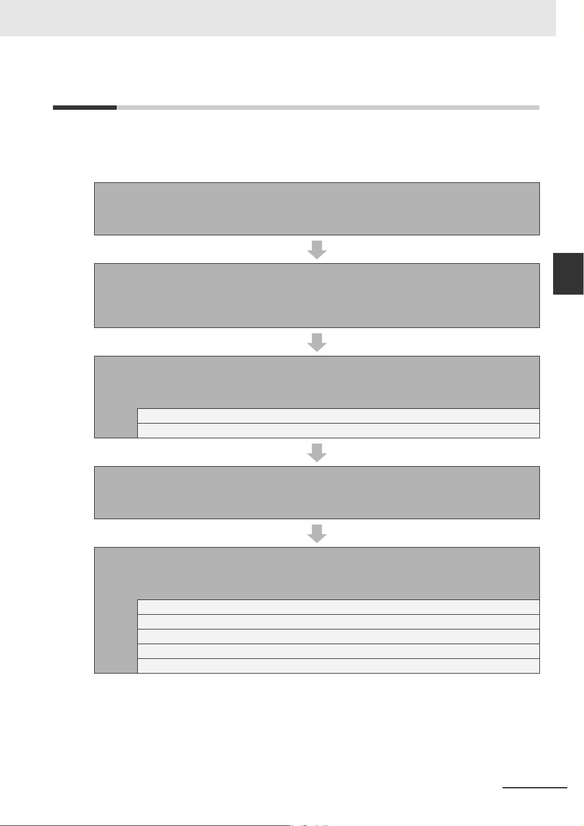
3-2 System Setup Procedures
The basic design flow to follow to design a Servo system is shown below.
The startup operations in this Guide are described in the following steps.
STEP 1. Create a Project (page 3-4)
Create a project file.
STEP 2. Create the EtherCAT Network Configuration (page 3-7)
Create the EtherCAT slave configuration that will connect to the CPU Unit’s built-in EtherCAT port.
STEP 3. Start Programming (page 3-9)
Register an axis variable and create and check the POU program.
STEP 3-1 Set the axis (page 3-9).
STEP 3-2 Create the program (page 3-17) and check the program (page 3-27).
3-2 System Setup Procedures
3
STEP 4. Transfer the Project to the CPU Unit (page 3-28)
Transfer the project, which contains the user program, to the CPU Unit.
STEP 5. Confirm System Operation (page 3-32)
Perform a check to test system operation. (Use online debugging.)
STEP 5-1 Check for Controller errors (page 3-32).
STEP 5-2 Reset the Absolute Encoder from the Sysmac Studio (page 3-35).
STEP 5-3 Check the Servo Drive wiring (page 3-38).
STEP 5-4 Check program operation (page 3-44).
STEP 5-5 Use data tracing to check operation (page 3-50).
NJ/NX-series Startup Guide for Motion Control (W514)
3-3
Page 30
3 Setting Up a Single-axis Servo System
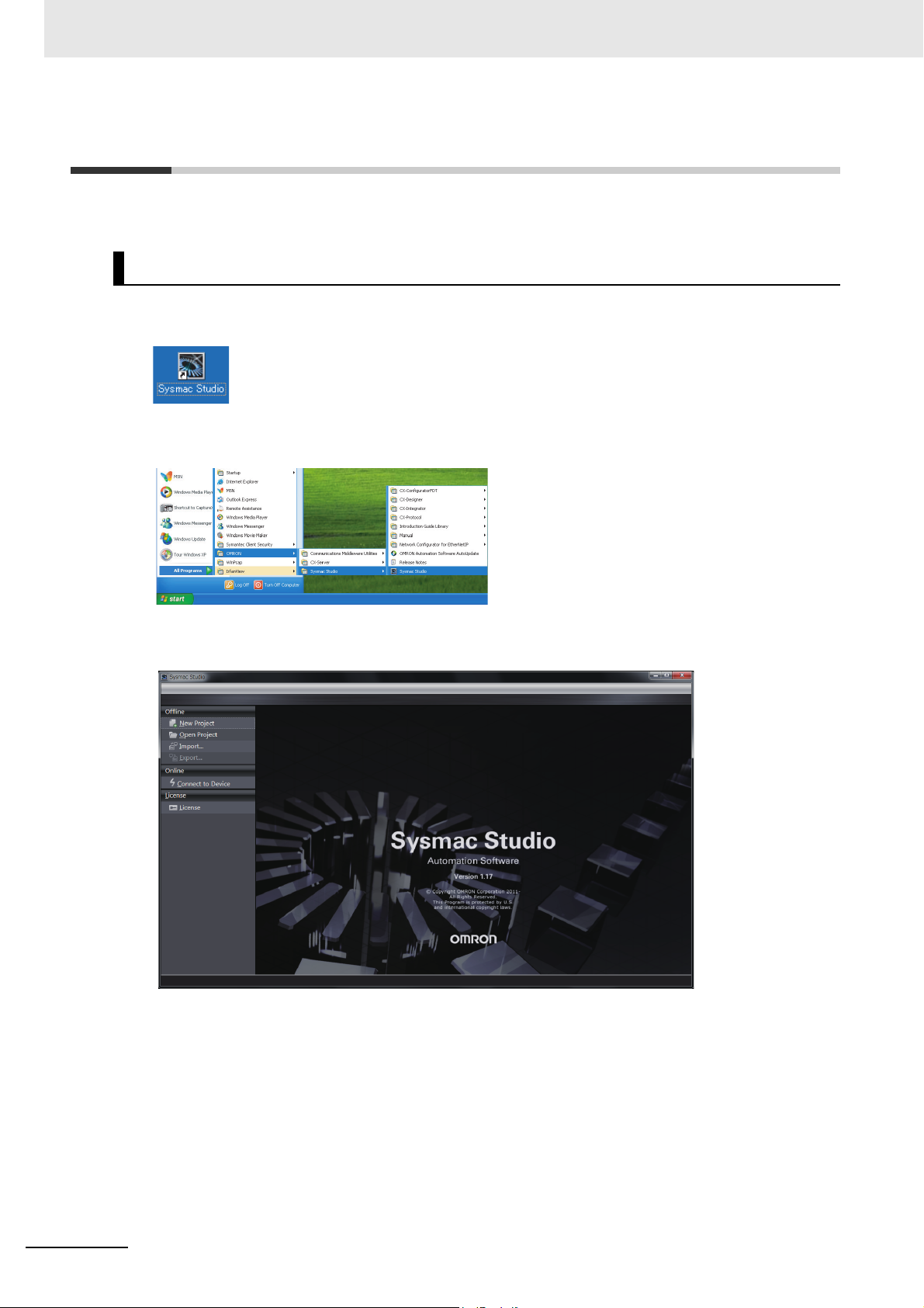
3-3 Creating a Project
Start the Sysmac Studio and create a project.
Starting the Sysmac Studio
Use one of the following methods to start the Sysmac Studio.
• Double-click the Sysmac Studio shortcut icon on your desktop.
• Select All Programs
OMRON Sysmac Studio Sysmac Studio from the Windows Start Menu.
The Sysmac Studio starts and the following window is displayed.
3-4
NJ/NX-series Startup Guide for Motion Control (W514)
Page 31

Creating a Project
Create a project in the Sysmac Studio.
1
Click the New Project Button in the Project Window.
Click the Button.
3 Setting Up a Single-axis Servo System
3-3 Creating a Project
3
2
In the Project Properties Dialog Box, select NXP12-1140DT in the Device Box and the version
to use in the Version Box, and then click the Create Button.
• Select the following device:
NXP12-1140DT
• Select the version you will use.
Click the Button.
A project file is created and the following window is displayed.
This concludes the procedure to create a project file.
NJ/NX-series Startup Guide for Motion Control (W514)
3-5
Page 32

3 Setting Up a Single-axis Servo System
Programming
Header
Configurations
and Setup Header
(1)
(7)
(6)
(5)(4)
(3)
(10) (11) (12) (13)(9)(8)
(2)
Menu bar
Toolbar
Status Bar
Parts of the Window
This section gives the names and functions of the parts of the Sysmac Studio Window.
No. Name
(1) Multiview Explorer This pane is your access point for all Sysmac Studio data. It is separated
into Configurations and Setup and Programming Layers.
(2) Filter Pane The Filter Pane allows you to search for color codes and for items with an
error icon. The results are displayed in a list.
(3) Edit Pane The Edit Pane is used to display and edit the data for any of the items.
It is separated into Configurations and Setup and Programming Layers.
(4) Toolbox The Toolbox shows the objects that you can use to edit the data that is
displayed in the Edit Pane.
(5) Search and Replace Pane In this pane, you can search for and replace strings in the data in the Pro-
gramming Layer.
(6) Controller Status Pane The Controller Status Pane shows the current operating status of the
Controller. The Controller Status Pane is displayed only while the Sysmac
Studio is online with the Controller.
(7) Simulation Pane The Simulation Pane is used to set up, start, and stop the Simulator for
the Controller.
(8) Cross Reference Tab Page A Cross Reference Tab Page displays a list of where variables, data
types, I/O ports, functions, and function blocks are used in the Sysmac
Studio.
(9) Output Tab Page The Output Tab Page shows the results of building.
(10) Watch Tab Page The Watch Tab Page shows the monitor results of the Simulator or online
Controller.
(11) Build Tab Page The Build Tab Page shows the results of program checks and building.
(12) Search and Replace Results
Tab Page
(13) Differential Monitor Tab Page You can detect the number of times the specified BOOL variable or mem-
The Search and Replace Results Tab Page shows the results when
Search All or Replace All is executed.
ber changes to TRUE or FALSE and display the count in this tab page.
3-6
Refer to the Sysmac Studio Version 1 Operation Manual (Cat. No. W504) for details on the Sysmac
Studio panes and tab pages.
NJ/NX-series Startup Guide for Motion Control (W514)
Page 33

3 Setting Up a Single-axis Servo System
3-4 Creating the EtherCAT Network
Configuration
A R88D-1SN01L-ECT Servo Drive is registered in the EtherCAT network configuration to operate as
axis 0.
1
Double-click EtherCAT under Configurations and Setups in the Multiview Explorer.
3-4 Creating the EtherCAT Network Configuration
3
The EtherCAT Tab Page is displayed in the Edit Pane.
NJ/NX-series Startup Guide for Motion Control (W514)
3-7
Page 34

3 Setting Up a Single-axis Servo System
Additional Information
2
Drag the R88D-1SN01L-ECT from the Toolbox to the master on the EtherCAT Tab Page.
The Servo Drive is added under the master with a node address of 1.
This concludes the creation of the EtherCAT network configuration.
If the physical EtherCAT network configuration is already connected, you can automatically create the virtual network configuration in the Sysmac Studio based on the physical network configuration.
Refer to the Sysmac Studio Version 1 Operation Manual (Cat. No. W504) for specific proce-
dures.
3-8
NJ/NX-series Startup Guide for Motion Control (W514)
Page 35

3-5 Programming
In this section we will create the user program.
A Servo axis for axis 0 will be added and set up, and a program will be created to control the Servo
Drive.
3-5-1 Setting the Axis
This section describes how to add the axis that is used to control the Servo Drive, assign it to the Servo
Drive, and set the axis parameters. In this example, the Control Function of the axis to add is set to Single-axis Position Control Axis in order to perform single-axis position control.
3 Setting Up a Single-axis Servo System
3-5 Programming
3
3-5-1 Setting the Axis
Adding the Axis Settings
Add the axis settings for axis 0.
1
Right-click Axis Settings in the Multiview Explorer and select Add Single-axis Position
Control Axis from the menu.
NJ/NX-series Startup Guide for Motion Control (W514)
3-9
Page 36

3 Setting Up a Single-axis Servo System
Axis 0 is added to the Multiview Explorer.
The axis is added as MC_Axis000. This axis is called axis 0.
Assigning a Servo Drive to the Axis
Next, assign the Servo Drive in the EtherCAT network configuration to the new axis 0 (MC_Axis000).
1
Right-click MC_Axis000 (axis 0) in the Multiview Explorer and select Edit from the menu.
3-10
NJ/NX-series Startup Guide for Motion Control (W514)
Page 37

3 Setting Up a Single-axis Servo System
The Axis Basic Settings are displayed on the Axis Parameter Settings Tab Page in the Edit
Pane.
3-5 Programming
3
3-5-1 Setting the Axis
2
Select Servo axis in the Axis type Box.
NJ/NX-series Startup Guide for Motion Control (W514)
3-11
Page 38

3 Setting Up a Single-axis Servo System
3
Select thne Servo Drive to use in the Output device Box (Node: 1, Device: R88D-1SN01L-ECT).
This will assign node 1 and device R88D-1SN01L-ECT as the output device for axis 0.
3-12
Now, node 1 with device R88D-1SN01L-ECT can be used as an axis in the EtherCAT network
configuration.
NJ/NX-series Startup Guide for Motion Control (W514)
Page 39

3 Setting Up a Single-axis Servo System
Setting the Axis Parameters
Set the axis parameters for axis 0 based on the mechanical configuration of the system.
The input axis parameters are shown in the following table according to the mechanical configuration of
axis 0.
Icon on Settings Tab Page Item Set value
Unit Conversion Settings Unit of Display mm
Command Pulse Count Per Motor
Rotation
Work Travel Distance per Motor
Rotation
Operation Settings Maximum Velocity 500 mm/s
8,388,608
10.000 mm
3-5 Programming
Maximum Jog Velocity 50 mm/s
Position Count Settings Encoder type Absolute encoder
1
Set the parameters on the Axis Parameter Settings Tab Page.
Click an icon on the Axis Parameter Settings Tab Page to display the settings for that particular
icon.
Set the axis parameters as indicated below.
• Unit Conversion Settings
3
3-5-1 Setting the Axis
NJ/NX-series Startup Guide for Motion Control (W514)
3-13
Page 40

3 Setting Up a Single-axis Servo System
• Operation Settings
• Position Count Settings
3-14
NJ/NX-series Startup Guide for Motion Control (W514)
Page 41

3 Setting Up a Single-axis Servo System
Additional Information
You can also set the parameters for all axes on the same tab page.
Right-click Axis Settings in the Multiview Explorer and select Axis Setting Table from the menu
to display the Axis Setting Table. The Axis Setting Table allows you to set the axis settings and
axis parameters for all axes that have been added.
3-5 Programming
3
3-5-1 Setting the Axis
NJ/NX-series Startup Guide for Motion Control (W514)
3-15
Page 42

3 Setting Up a Single-axis Servo System
Confirming That the Axis Variable Is Registered
A structure variable that is defined to hold information on an axis, such as physical quantities, status,
and error information, is called an axis variable.
The axis variables are used in the user program to specify axes.
When an axis is added, an axis variable for that axis is automatically added to the global variable table.
Use the following method to check the axis variables.
1
Right-click Global Variables under Programming - Data in the Multiview Explorer and select
Edit from the menu.
The global variable table is displayed in the Edit Pane.
You can confirm that the MC_Axis000 axis variable for axis 0 has been added automatically.
3-16
NJ/NX-series Startup Guide for Motion Control (W514)
Page 43

Precautions for Correct UsePrecautions for Correct Use
3-5-2 Creating the Program
Create the instructions that control the Servo Drive in section 0 of program 0. Program 0 is automatically created when you create a project.
The following instructions are created. To do so, we will use an axis variable and motion control instructions.
3 Setting Up a Single-axis Servo System
3-5 Programming
3
3-5-2 Creating the Program
Refer to the NJ/NX-series Startup Guide for CPU Units (Cat. No. W513) for details on how to create
ladder diagrams.
The sample programming that is provided in this Guide includes only the programming that is
required to operate the Servomotors. When programming actual applications, also program
EtherCAT communications, device interlocks, I/O with other devices, and other control procedures.
NJ/NX-series Startup Guide for Motion Control (W514)
3-17
Page 44

3 Setting Up a Single-axis Servo System
Opening the Ladder Editor
To enter the program, you must start the Ladder Editor and open section 0 of program 0.
1
Right-click Section0 under Programming POUs Programs Program0 in the Multiview
Explorer, and select Edit from the menu.
The local variable table and Ladder Editor are displayed in the Edit Pane. From here, you can
register local variables and create a ladder diagram.
3-18
NJ/NX-series Startup Guide for Motion Control (W514)
Page 45

3 Setting Up a Single-axis Servo System
Enter an input for the ServoLock variable
to control turning the Servo ON and OFF.
Definitions of any variables that you enter in the Ladder Editor
are automatically registered in the local variable table.
Creating the Instructions That Turn the Servo ON and OFF
You must turn ON the Servo in order to execute single-axis positioning from the Servo Drive. The
MC_Power (Power Servo) instruction is used to control turning the Servo ON and OFF.
1
Enter an input for the ServoLock variable to control turning the Servo ON and OFF.
3-5 Programming
3
3-5-2 Creating the Program
• How to enter an NO input
Right-click the horizontal line in the Ladder Editor and select Insert Input from the menu. Or,
press the C Key.
• How to display external variables and internal variables
Select Variable Table from the View menu.
2
Drag MC_Power from the Motion Area of the Toolbox to the right side of the ServoLock input.
NJ/NX-series Startup Guide for Motion Control (W514)
3-19
Page 46

3 Setting Up a Single-axis Servo System
Enter Power1 as the instance name.
Definitions of any variables for instance names that you enter in the
Ladder Editor are automatically registered in the local variable table.
An MC_Power instruction is inserted to the right of the ServoLock input.
3
Enter Power1 as the instance name for the MC_Power instruction.
3-20
NJ/NX-series Startup Guide for Motion Control (W514)
Page 47

3 Setting Up a Single-axis Servo System
Enter MC_Axis000 (the axis variable
of axis 0).
Enter the initial letter "m" to display
the selectable axis variables.
The variable automatically
appears on the output side when
it is entered on the input side.
4
Enter the in-out variable for the Power1 instance.
Specify the axis variable of the axis to control for the Axis in-out variable of the Power1 instance.
The axis variable for axis 0 is MC_Axis000.
3-5 Programming
3
3-5-2 Creating the Program
This concludes the creation of the instructions to control turning the Servo ON and OFF.
NJ/NX-series Startup Guide for Motion Control (W514)
3-21
Page 48

3 Setting Up a Single-axis Servo System
Creating the Instructions That Perform Single-axis Positioning
Here, the MC_MoveRelative (Relative Positioning) instruction is used to perform single-axis control.
We will use two instances of this instruction to repeatedly perform round-trip operation with single-axis
positioning.
1
Enter an input for the Start1 variable to control the Relative Positioning instruction.
To add a rung, select the left bus bar and press the R Key.
Definitions of any variables that you enter
in the Ladder Editor are automatically
registered in the local variable table.
Enter an input for the Start1 variable to
control the Relative Positioning instruction.
2
Enter an NC input for the Complete1 variable to control the repeated single-axis positioning.
To enter an NC input, select the horizontal line in the Ladder Editor and press the / Key.
Definitions of any variables that you enter in the Ladder
Editor are automatically registered in the local variable table.
Enter an NC input for the Complete1 variable, which is
turned ON when the round-trip operation is completed.
3-22
NJ/NX-series Startup Guide for Motion Control (W514)
Page 49

3 Setting Up a Single-axis Servo System
Insert an MC_MoveRelative
(Relative Positioning) instruction.
Enter Move1 as the instance name.
Definitions of variables for any instance names that you enter in the
Ladder Editor are automatically registered in the local variable table.
3
Insert an MC_MoveRelative (Relative Positioning) instruction.
3-5 Programming
3
3-5-2 Creating the Program
4
Enter Move1 as the instance name for the MC_MoveRelative instruction.
NJ/NX-series Startup Guide for Motion Control (W514)
3-23
Page 50

3 Setting Up a Single-axis Servo System
Enter MC_Axis000 (the axis
variable of axis 0).
The variable automatically
appears on the output side when
it is entered on the input side.
5
Enter the in-out variable for the Move1 instance.
Specify the axis variable of the axis to control for the Axis in-out variable of the Move1 instance.
The axis variable for axis 0 is MC_Axis000.
3-24
NJ/NX-series Startup Guide for Motion Control (W514)
Page 51

3 Setting Up a Single-axis Servo System
Set the values of the input variables.
6
Enter the values given in the following table for the input variables of the MC_MoveRelative
instruction.
Input variable Meaning Set value
Distance Travel Distance (mm) 20
Velocity Target Velocity (mm/s) 10
Acceleration
Deceleration
Acceleration Rate (mm/s
Deceleration Rate (mm/s
2
)
2
)
200
200
3-5 Programming
3
3-5-2 Creating the Program
NJ/NX-series Startup Guide for Motion Control (W514)
3-25
Page 52

3 Setting Up a Single-axis Servo System
Additional Information
Enter an output for the Complete1 variable to turn
ON when the round-trip operation is completed.
7
Insert the second MC_MoveRelative (Relative Positioning) instruction.
Enter Move2 as the instance name, enter the axis variable of axis 0 (MC_Axis000) for the in-out
variable, and enter the values in the following table for the input variables.
Input variable Meaning Set value
Distance Travel Distance (mm) 20
Velocity Target Velocity (mm/s) 10
Acceleration
Deceleration
Acceleration Rate (mm/s
Deceleration Rate (mm/s
Insert the second MC_MoveRelative (Relative Positioning) instruction
as follows:
a. Insert an MC_MoveRelative (Relative Positioning) instruction.
b. Enter Move2 as the instance name.
c. Enter MC_Axis000 (the axis variable of axis 0) for the in-out variable.
d. Set the values of the input variables.
2
)
2
)
200
200
c.
d.
b.
a.
Cascade connections are possible for Ladder Diagram Instructions (e.g., LD (Load) and AND
(AND)), for FB instructions (e.g., MC_MoveRelative (Relative Positioning)), and for FUN instructions (e.g., MOVE (Move)). In this program, the Move2 instance is started after relative positioning for the Move1 instance is completed.
8
Enter an output for the Complete1 variable to turn ON when the round-trip operation is com-
pleted.
3-26
This concludes the creation of the instructions to repeatedly execute single-axis positioning.
NJ/NX-series Startup Guide for Motion Control (W514)
Page 53

3-5-3 Checking the Program
Useful Function
Double-click any error line to
jump to the rung where the
error was detected.
Check the program that you created.
1
Select Check All Programs from the Project Menu.
3 Setting Up a Single-axis Servo System
3-5 Programming
3
3-5-3 Checking the Program
The results of the program check are displayed on the Build Tab Page.
If there are any errors, correct them.
Warnings such as "A parameter is not entered for the output." may be displayed because variables and actual inputs are not assigned in the I/O map. In this case, ignore the warnings and
continue the procedure.
NJ/NX-series Startup Guide for Motion Control (W514)
3-27
Page 54

3 Setting Up a Single-axis Servo System
The Sysmac Studio goes
online and the color of the
bar at the top of the Edit
Pane changes to yellow.
The Controller status is
displayed.
3-6 Transferring the Project to the CPU
Unit
The project, which contains the user program, is transferred to the CPU Unit.
Turn ON the power supply to the Controller and to the Servo Drive.
Online Connection
1
Use one of the following methods to go online.
Method 1: Select Online from the Controller
Menu.
Method 2: Click the Button on the
Toolbar.
Method 3: Press the Ctrl + W
Keys.
The CPU Unit name is written to the Controller, and the Sysmac Studio goes online with the
Controller.
Ctrl
W
3-28
NJ/NX-series Startup Guide for Motion Control (W514)
Page 55

3 Setting Up a Single-axis Servo System
The results of comparison of the data on the
computer and the data in
the physical Controller
are displayed.
Click this button to transfer
the project from the
computer to the CPU Unit.
Click this button to transfer
the project from the CPU
Unit to the computer.
Transferring the Project
You must transfer the project to the CPU Unit. The synchronize operation is used to transfer the
project. Here, “synchronize” means to automatically compare the data for the Sysmac Studio on the
computer with the data in the physical Controller and transfer the data in the direction that is specified by the user.
1
Use one of the following methods to display the Synchronize Pane.
Method 1: Select Synchronize from the
Controller Menu.
Method 2: Click the Button on the
Toolbar.
Method 3: Press the Ctrl + M
Keys.
Ctrl
M
3-6 Transferring the Project to the CPU Unit
3
Comparison of the data on the computer and the data in the physical Controller is started.
The comparison results are displayed after the comparison is completed.
NJ/NX-series Startup Guide for Motion Control (W514)
3-29
Page 56

3 Setting Up a Single-axis Servo System
2
Click the Transfer to Controller Button.
Click the Button.
3
Click the Yes Button.
Click the Button.
The operating mode changes to PROGRAM mode, and the Sysmac Studio starts transferring
the project to the CPU Unit. During the transfer, a progress bar appears in the Synchronize
Pane.
4
The following dialog box is displayed when the transfer is completed. Click the No Button.
Do not change to RUN mode at this time (i.e., remain in PROGRAM mode).
Click the Button.
3-30
NJ/NX-series Startup Guide for Motion Control (W514)
Page 57

3 Setting Up a Single-axis Servo System
5
Click the Close Button at the lower right of the Synchronize Pane.
Click the Button.
The Synchronize Pane closes.
3-6 Transferring the Project to the CPU Unit
3
NJ/NX-series Startup Guide for Motion Control (W514)
3-31
Page 58

3 Setting Up a Single-axis Servo System
3-7 Confirming System Operation
Confirm that the system is operating correctly.
Place the CPU Unit online with the Sysmac Studio before you perform the procedures that are given in
this section.
3-7-1 Checking for Controller Errors
The color of the ERR/ALM indicator in the Controller Status Pane of the Sysmac Studio shows the
presence of any errors. If ERR/ALM is red, an error has occurred. Follow the instructions that are given
below to check the details of the error.
1
Click the Button on the Toolbar of the Controller Status Pane.
The Detailed View of the Controller Status Pane is displayed.
Indicates a Controller error.
2
Use one of the following methods to open the Troubleshooting Window.
Method 1: Select Troubleshooting from the
Tools Menu.
3-32
Method 2: Click the Button on the Toolbar.
NJ/NX-series Startup Guide for Motion Control (W514)
Page 59

3 Setting Up a Single-axis Servo System
A list of Controller
errors is displayed.
Details on the errors and possible
solutions are displayed in this area.
Click the Display Switch Button to
switch between the detailed error
information and possible solutions.
The Troubleshooting Window is displayed for the Edit Pane.
From there, you can check detailed information on any errors that have occurred and find out
how to troubleshoot them.
3-7 Confirming System Operation
3
3-7-1 Checking for Controller Errors
3
4
Click the Button.
5
Click the Button.
Refer to the error details and troubleshooting information to solve the problems and eliminate all
errors.
Click the Reset All Button in the Troubleshooting Window.
The following confirmation dialog box appears.
Click the Yes Button.
All errors are reset.
If the cause of the error is not removed, the error will occur again.
NJ/NX-series Startup Guide for Motion Control (W514)
3-33
Page 60

3 Setting Up a Single-axis Servo System
Additional Information
• If an EtherCAT communications cable is not properly connected or if power is not supplied to a
Remote I/O Unit, a minor fault level Controller error (a Link OFF Error or Network Configuration Verification Error) will occur. If you are sure that all EtherCAT communications cables are
properly connected, first check to make sure that power is being supplied to the Remote I/O
Units before you reset the errors.
• If you use the default Servo parameters, you must wire the immediate stop input, negative
drive prohibit input, and the positive drive prohibit input.
If these inputs are not wired, the CPU Unit will remain in the drive prohibit signal and emergency stop signal detected state, and a minor fault level Controller error will occur. The minor
fault level Controller errors that will occur are an Immediate Stop Input Error and a Drive Prohibition Input Error. (The event codes are 68220000 and 64E30000.)
If the above signals are temporarily not wired while commissioning the system, you can
temporarily change the Servo parameters to prevent these errors from occurring in the CPU
Unit. Refer to A-1 Settings When Control Input Signals Are Not Wired for details on the settings that you must change in this case.
3-34
NJ/NX-series Startup Guide for Motion Control (W514)
Page 61

3 Setting Up a Single-axis Servo System
3-7-2 Resetting the Absolute Encoder from the Sysmac Studio
The absolute encoder must be set up the first time it is used, and when the rotation data is initialized to 0.
1
Right-click the Servo Drive and select Setup and Tuning from the menu.
The Setup and Tuning Portal appears.
2
Click the Quick Parameter Setup and I/O Monitor Button.
3-7 Confirming System Operation
3
3-7-2 Resetting the Absolute Encoder from the Sysmac Studio
The following dialog box appears. Click the Yes Button.
The Motor and Encoder setting Page appears.
NJ/NX-series Startup Guide for Motion Control (W514)
3-35
Page 62

3 Setting Up a Single-axis Servo System
3
Click the Launch Motor and Encoder view Button.
The Encoder Properties Tab Page appears.
4
Click the Clear system Button.
An Absolute Value Clear Error (error display number: 2701) will occur, and a dialog box indicating "Restart the drive to complete the operation."
3-36
NJ/NX-series Startup Guide for Motion Control (W514)
Page 63

3 Setting Up a Single-axis Servo System
5
Click the Yes Button.
The multiple rotation data of the absolute encoder is cleared.
3-7 Confirming System Operation
3
3-7-2 Resetting the Absolute Encoder from the Sysmac Studio
NJ/NX-series Startup Guide for Motion Control (W514)
3-37
Page 64

3 Setting Up a Single-axis Servo System
3-7-3 Checking the Servo Drive Wiring
Use the MC Test Run operation in the Sysmac Studio to check the wiring of the Servo Drive.
The wiring is checked in PROGRAM mode to prevent a user program for which operation has not been
verified from affecting the wiring confirmation results. In this Guide, the project is transferred in PROGRAM mode.
An MC Test Run allows you to perform tasks such as monitoring the control inputs of an OMRON Servo
Drive that has been assigned to an axis or operating the Servomotor without any user programming.
Use this to check the Servo Drive wiring and the operation of the Servomotor.
Starting an MC Test Run
Start an MC Test Run from the Sysmac Studio.
1
Right-click MC_Axis000(0) under Configurations and Setup - Motion Control Setup - Axis
Settings in the Multiview Explorer, and select Start MC Test Run from the menu.
3-38
NJ/NX-series Startup Guide for Motion Control (W514)
Page 65

3 Setting Up a Single-axis Servo System
2
When the following caution dialog box appears, read the message carefully. After you confirm
safety, click the OK Button.
3-7 Confirming System Operation
3
3-7-3 Checking the Servo Drive Wiring
The MC Test Run Tab Page is displayed in the Edit Pane.
NJ/NX-series Startup Guide for Motion Control (W514)
3-39
Page 66

3 Setting Up a Single-axis Servo System
Checking the Control Input Signal Wiring
Use the control input signal status indicators on the MC Test Run Tab Page in the Sysmac Studio to
check the wiring of the control input signals.
1
Select the axis to check on the MC Test Run Tab Page.
2
Check to see if the signals turn ON and OFF properly on the monitor screen by turning ON and
OFF the sensor connected to each control input signal.
3-40
NJ/NX-series Startup Guide for Motion Control (W514)
Page 67

Precautions for Correct UsePrecautions for Correct Use
Checking the Servomotor Wiring
3 Setting Up a Single-axis Servo System
Use the MC Test Run Tab Page in the Sysmac Studio to check the Servomotor wiring.
• When one of the following operations is performed for a command from the Sysmac Studio,
the Servomotor will operate at the set velocity: Servo ON, jogging, relative positioning, absolute positioning, or homing.
Always confirm that it is safe for the Servomotor to operate before executing any of these
operations.
• When operating the Controller from the Sysmac Studio, always install external emergency circuits so that the Servomotor can be stopped safely whenever necessary. The Sysmac Studio
may not be able to send commands under some circumstances, e.g., if an error occurs in the
computer.
• Set the EtherCAT communications and establish communications before you attempt to perform operation from the Sysmac Studio.
Servo ON
You can use the Servo ON Button to turn the Servo ON and OFF.
1
Select the axis to check on the MC Test Run Tab Page.
3-7 Confirming System Operation
3
3-7-3 Checking the Servo Drive Wiring
2
Click the Servo ON Button.
The Servo is turned ON for the selected axis.
Click the Servo OFF Button in this state to turn the Servo OFF.
NJ/NX-series Startup Guide for Motion Control (W514)
3-41
Page 68

3 Setting Up a Single-axis Servo System
Jogging
Jog the axis in the Servo ON state.
1
Click the Jogging Tab on the MC Test Run Tab Page.
2
Enter the target velocity, acceleration rate, and deceleration rate, and then click the Apply But-
ton. For this example, set the target velocity to 50.
3
Click the Button or the Button.
The motor will operate in either the positive or negative direction while one of these buttons is
clicked.
Check to see if the motor operates in the set direction.
3-42
NJ/NX-series Startup Guide for Motion Control (W514)
Page 69

Ending the MC Test Run
3 Setting Up a Single-axis Servo System
After you have checked the wiring of the control input signals and the Servomotor, end the MC Test
Run operation.
1
Right-click MC_Axis000(0) under Configurations and Setup - Motion Control Setup - Axis
Settings in the Multiview Explorer, and select Stop MC Test Run from the menu.
This ends the MC Test Run operation.
3-7 Confirming System Operation
3
3-7-3 Checking the Servo Drive Wiring
NJ/NX-series Startup Guide for Motion Control (W514)
3-43
Page 70

3 Setting Up a Single-axis Servo System
3-7-4 Checking Program Operation
You will change the operating mode of the CPU Unit to RUN mode and then use monitoring, control
BOOL variables (set/reset), and use the MC Monitor Table in the Ladder Editor to check the operation
of the program that you created. Control (set/reset) the status of the inputs to control the motion control
instructions, and use the MC Monitor Table to check the results of their execution.
1
Double-click Section0 under Programming POUs Programs Program0 in the Multiview
Explorer.
The ladder program is displayed in the monitored state in the Edit Pane.
3-44
NJ/NX-series Startup Guide for Motion Control (W514)
Page 71

3 Setting Up a Single-axis Servo System
2
Use one of the following methods to change the operating mode to RUN mode.
Method 1: Select Mode RUN Mode from
the Controller Menu.
Method 2: Click the Button on the
Toolbar.
Method 3: Press the Ctrl + 3
Keys.
3
The following dialog box is displayed. Confirm that no problem will occur even if you change the
operating mode, and then click the Yes Button.
Ctrl
3
3-7 Confirming System Operation
3
3-7-4 Checking Program Operation
NJ/NX-series Startup Guide for Motion Control (W514)
3-45
Page 72

3 Setting Up a Single-axis Servo System
4
Right-click ServoLock in the program in the Edit Pane, and then select Set/Reset - Set from the
menu.
ServoLock changes to TRUE, and Power1 is executed.
3-46
NJ/NX-series Startup Guide for Motion Control (W514)
Page 73

3 Setting Up a Single-axis Servo System
5
Right-click Start in the program in the Edit Pane, and then select Set/Reset - Set from the
menu.
3-7 Confirming System Operation
3
3-7-4 Checking Program Operation
Start1 changes to TRUE.
Move1 is executed and positioning is started. When the positioning for Move1 is completed,
Move1 execution stops and Move2 is executed. This operation is repeated.
NJ/NX-series Startup Guide for Motion Control (W514)
3-47
Page 74

3 Setting Up a Single-axis Servo System
6
Right-click Axis Settings under Configurations and Setup - Motion Control Setup in the
Multiview Explorer, and select MC Monitor Table from the menu.
The MC Monitor Table Tab Page is displayed in the Edit Pane.
3-48
NJ/NX-series Startup Guide for Motion Control (W514)
Page 75

3 Setting Up a Single-axis Servo System
a
b
7
Use the MC Monitor Table to confirm that the axis is moving.
a and b in the following figure show the information that you need to check.
• a: Check that the value of Pos under Cmd is either increasing or decreasing.
• b: Check that the value of Pos under Act is either increasing or decreasing.
3-7 Confirming System Operation
3
3-7-4 Checking Program Operation
NJ/NX-series Startup Guide for Motion Control (W514)
3-49
Page 76

3 Setting Up a Single-axis Servo System
3-7-5 Using Data Tracing to Check Operation
Use data tracing to check the current operation.
1
Right-click Data Trace Settings under Configurations and Setup in the Multiview Explorer
and select Add Data Trace from the menu.
DataTrace0 is added to the Multiview Explorer.
3-50
NJ/NX-series Startup Guide for Motion Control (W514)
Page 77

3 Setting Up a Single-axis Servo System
2
Double-click the new DataTrace0 item in the Multiview Explorer.
3-7 Confirming System Operation
3
3-7-5 Using Data Tracing to Check Operation
The DataTrace0 Tab Page is displayed in the Edit Pane.
NJ/NX-series Startup Guide for Motion Control (W514)
3-51
Page 78

3 Setting Up a Single-axis Servo System
3
Select the Enable trigger condition Check Box on the DataTrace0 Tab Page and enter the vari-
able to use as the trigger condition. For this example, use Program0.Move1.Execute.
4
Click the Add Target Button.
A trace variable line is added to the list.
3-52
NJ/NX-series Startup Guide for Motion Control (W514)
Page 79

3 Setting Up a Single-axis Servo System
5
Enter MC_Axis000.Cmd.Vel for the name of the variable to trace on the new line.
6
Click the Start Trace Button.
3-7 Confirming System Operation
3
3-7-5 Using Data Tracing to Check Operation
7
Make sure that the status bar at the lower left changes as shown in the following figure.
NJ/NX-series Startup Guide for Motion Control (W514)
3-53
Page 80

3 Setting Up a Single-axis Servo System
8
Make sure that the results of the data trace are displayed.
Make sure that the trace results show the same waveform as shown in 3-1 Single-axis Servo
System Operation.
3-54
NJ/NX-series Startup Guide for Motion Control (W514)
Page 81

Two-axis Linear Interpolation
Program
This section describes how to add an axis to the single-axis Servo system constructed
in Section 3 to create a two-axis linear interpolation program.
4-1 Two-axis Servo System Operation . . . . . . . . . . . . . . . . . . . . . . . . . . . . . . . . 4-2
4-2 System Setup Procedures . . . . . . . . . . . . . . . . . . . . . . . . . . . . . . . . . . . . . . . 4-3
4-3 Changing the Program . . . . . . . . . . . . . . . . . . . . . . . . . . . . . . . . . . . . . . . . . 4-4
4-3-1 Setting Axis 0 to a Motion Control Axis . . . . . . . . . . . . . . . . . . . . . . . . . . . . . . 4-4
4-3-2 Adding a Servo Drive to the EtherCAT Network Configuration . . . . . . . . . . . . 4-5
4-3-3 Adding Axis 1 and Setting an Axes Group . . . . . . . . . . . . . . . . . . . . . . . . . . . . 4-7
4-3-4 Adding Instructions and Checking the Program . . . . . . . . . . . . . . . . . . . . . . 4-15
4-3-5 Transferring the Project to the CPU Unit . . . . . . . . . . . . . . . . . . . . . . . . . . . . 4-21
4-4 Confirming System Operation . . . . . . . . . . . . . . . . . . . . . . . . . . . . . . . . . . 4-22
4-4-1 Checking the New Axis 1 . . . . . . . . . . . . . . . . . . . . . . . . . . . . . . . . . . . . . . . . 4-22
4-4-2 Checking Program Operation . . . . . . . . . . . . . . . . . . . . . . . . . . . . . . . . . . . . 4-22
4-4-3 Using Data Tracing to Check Operation . . . . . . . . . . . . . . . . . . . . . . . . . . . . . 4-29
4
NJ/NX-series Startup Guide for Motion Control (W514)
4-1
Page 82

4 Two-axis Linear Interpolation Program
800.000 mm
600.000 mm
0.000 mm
0.000 mm
X
Y
Linear 2
Linear 1
Axis 1
Interpolation velocity: 200.000 mm/s
Axis 0
Acceleration rate: 400.000 mm/s
2
Deceleration rate: 400.000 mm/s
2
4-1 Two-axis Servo System Operation
This section describes the operation of the two-axis Servo system that is set up in this Guide.
In this system, axis 0 and axis 1, which are set up for an XY stage, will repeatedly travel between two
points using linear interpolation.
The speed waveforms for axis 0 and axis 1 are shown below.
Velocity
Axis 0
Travel distance: 800.000 mm
Speed: 160.000 mm/s
Axis 1
Travel distance: 600.000 mm
Speed: 120.000 mm/s
The operation is
repeated.
Time
The axis created in Section 3 Setting Up a Single-axis Servo System is axis 0. The axis added in this
section is axis 1.
The mechanical configuration of axis 1 is the same as that of axis 0. Refer to 3-1 Single-axis Servo Sys-
tem Operation for the mechanical configuration of axis 0.
4-2
NJ/NX-series Startup Guide for Motion Control (W514)
Page 83

4 Two-axis Linear Interpolation Program
4-2 System Setup Procedures
The basic design flow to follow to design a Servo system is shown below.
This section describes how to add a new axis, continuing from the procedures performed in Section 3
Setting Up a Single-axis Servo System.
Therefore, any procedures that were completed in 3-2 System Setup Procedures are not included in
this section.
STEP 1. Correct the Program (page 4-4)
Add an axis variable and an axes group variable, and then correct the POU program and
check it.
STEP 1-1 Set axis 0 to a motion control axis (page 4-5).
STEP 1-2 Add a Servo Drive to the EtherCAT network configuration (page 4-5).
STEP 1-3 Add axis 1 and set axes group (page 4-7).
STEP 1-4 Add instructions and check the program (page 4-15).
STEP 1-5 Transfer the project to the CPU Unit (page 4-21).
STEP 2. Confirm System Operation (page 4-22)
Perform a check to test system operation. (Use online debugging.)
STEP 2-1 Check program operation (page 4-22).
STEP 2-2 Use data tracing to check operation (page 4-29).
4-2 System Setup Procedures
4
NJ/NX-series Startup Guide for Motion Control (W514)
4-3
Page 84

4 Two-axis Linear Interpolation Program
4-3 Changing the Program
Change the program to perform linear interpolation control between two axes.
Correct the program that was created in Section 3 Setting Up a Single-axis Servo System as follows:
• Set axis 0 to a motion control axis.
• Add the second Servo Drive to the EtherCAT network configuration.
• Add an axis for the second Servo Drive, and create an axes group that contains axis 0 and axis 1.
• Add programming to perform linear interpolation control.
4-3-1 Setting Axis 0 to a Motion Control Axis
To perform linear interpolation control between two axes, change the setting of axis 0 that was created
in Section 3 Setting Up a Single-axis Servo System from a single-axis position control axis to a
motion control axis.
1
Right-click MC_Axis000 (axis 0) in the Multiview Explorer and select Edit from the menu.
The Axis Basic Settings are displayed on the Axis Parameter Settings Tab Page in the Edit Pane.
4-4
NJ/NX-series Startup Guide for Motion Control (W514)
Page 85

2
Select All in the Control function Box.
4 Two-axis Linear Interpolation Program
4-3 Changing the Program
Selecting All enables the axis to be used for both single-axis position control and two-axis linear
interpolation control.
4-3-2 Adding a Servo Drive to the EtherCAT Network Configuration
A R88D-1SN01L-ECT Servo Drive is added as part of the EtherCAT network configuration that was
created in Section 3 Setting Up a Single-axis Servo System. This Servo Drive will operate as axis 1.
1
Double-click EtherCAT under Configurations and Setups in the Multiview Explorer.
4
4-3-2 Adding a Servo Drive to the EtherCAT Network Configuration
NJ/NX-series Startup Guide for Motion Control (W514)
4-5
Page 86

4 Two-axis Linear Interpolation Program
The EtherCAT Tab Page is displayed in the Edit Pane.
2
Right-click R88D-1SN01L-ECT in the Toolbox, and select Insert from the menu.
The Servo Drive is added under E001 with a node address of 2.
4-6
This concludes the creation of the EtherCAT network configuration.
NJ/NX-series Startup Guide for Motion Control (W514)
Page 87

4 Two-axis Linear Interpolation Program
4-3-3 Adding Axis 1 and Setting an Axes Group
Add the axis settings for axis 1, and then set up the axes group to perform interpolation.
Adding the Axis Settings for Axis 1
1
Right-click Axis Settings in the Multiview Explorer and select Add - Motion Control Axis from
the menu.
4-3 Changing the Program
An axis is added to the Multiview Explorer.
The axis is added as MC_Axis001. This axis is called axis 1.
4
4-3-3 Adding Axis 1 and Setting an Axes Group
NJ/NX-series Startup Guide for Motion Control (W514)
4-7
Page 88

4 Two-axis Linear Interpolation Program
Assigning the Axis and Setting the Axis Parameters
Assign a Servo Drive to MC_Axis001 (the new axis 1), and set its axis parameters.
You could use the same procedures as described in the Assigning a Servo Drive to the Axis on page
3-10 and Setting the Axis Parameters on page 3-13 in 3-5-1 Setting the Axis.
For this example, we will use the Axis Setting Table to copy the settings from axis 0 to axis 1.
1
Right-click Axis Settings under Configurations and Setup - Motion Control Setup in the
Multiview Explorer, and select Axis Setting Table from the menu.
The Axis Setting Table is displayed in the Edit Pane.
The axis parameters for axis 0 (1 MC_Axis000(0)) are already set, but the axis parameters for
axis 1 (2 MC_Axis001(1)) are still set to their default values.
4-8
NJ/NX-series Startup Guide for Motion Control (W514)
Page 89

4 Two-axis Linear Interpolation Program
2
Right-click 1 MC_Axis000(0) and select Copy from the menu.
4-3 Changing the Program
3
Right-click 2 MC_Axis001(1) and select Paste from the menu.
The settings of the axis parameters for axis 0 are copied to axis 1.
4
4-3-3 Adding Axis 1 and Setting an Axes Group
In this state, the input device for axis 1 still needs to be assigned to a Servo Drive.
NJ/NX-series Startup Guide for Motion Control (W514)
4-9
Page 90

4 Two-axis Linear Interpolation Program
4
Click the Input device Cell in the 2 MC_Axis001(1) column, and select Node: 2, Device: R88D-
1SN01L-ECT.
This will assign node 2 and device R88D-1SN01L-ECT as the input device for axis 1.
Now, node 2 with device R88D-1SN01L-ECT can be used as an axis in the EtherCAT network
configuration.
4-10
NJ/NX-series Startup Guide for Motion Control (W514)
Page 91

Adding Axes Group Settings
1
Right-click Axes Group Settings under Configurations and Setup - Motion Control Setup in
the Multiview Explorer and select Add - Axes Group Settings from the menu.
4 Two-axis Linear Interpolation Program
4-3 Changing the Program
An axes group is added to the Multiview Explorer.
The new axes group is displayed as MC_Group000.
4
4-3-3 Adding Axis 1 and Setting an Axes Group
NJ/NX-series Startup Guide for Motion Control (W514)
4-11
Page 92

4 Two-axis Linear Interpolation Program
2
Right-click the group that you added in the Multiview Explorer and select Edit from the menu.
The axes group settings are displayed on the Axes Group Basic Settings Display in the Edit
Pane.
4-12
NJ/NX-series Startup Guide for Motion Control (W514)
Page 93

4 Two-axis Linear Interpolation Program
3
Set the Axes Group Basic Settings for axes group 0 as shown in the following figure.
This concludes the axes group settings.
4-3 Changing the Program
4
4-3-3 Adding Axis 1 and Setting an Axes Group
NJ/NX-series Startup Guide for Motion Control (W514)
4-13
Page 94

4 Two-axis Linear Interpolation Program
Confirming That the Axes Group Variable Is Registered
System-defined variables for axes groups are called Axes Group Variables.
You can use axes group variables in the user program to enable the execution of axes group
motion control instructions or to access the status of the axes groups.
When axes group settings are added, an axes group variable is automatically added to the global variable table.
Use the following procedure to check axes group variables.
1
Right-click Global Variables under Programming - Data in the Multiview Explorer and select
Edit from the menu.
The global variable table where the MC_Group000 axes group variable was registered is displayed in the Edit Pane.
4-14
NJ/NX-series Startup Guide for Motion Control (W514)
Page 95

4 Two-axis Linear Interpolation Program
Precautions for Correct UsePrecautions for Correct Use
4-3-4 Adding Instructions and Checking the Program
Instructions to perform linear interpolation of the Servo Drives for two axes is added to the program that
was created in Section 3 Setting Up a Single-axis Servo System, and then the program is checked.
The following instructions are added. To do so, we will use axis variables, an axes group variable, and
motion control instructions.
4-3 Changing the Program
Refer to the NJ/NX-series Startup Guide for CPU Units (Cat. No. W513) for details on how to create
ladder diagrams.
The sample programming that is provided in this Guide includes only the programming that is
required to operate the Servomotors. When programming actual applications, also program
EtherCAT communications, device interlocks, I/O with other devices, and other control procedures.
4
4-3-4 Adding Instructions and Checking the Program
NJ/NX-series Startup Guide for Motion Control (W514)
4-15
Page 96

4 Two-axis Linear Interpolation Program
Adding Instructions
Add the instructions that control linear interpolation of the Servo Drives for two axes.
Opening the Ladder Editor
To enter the program, you must start the Ladder Editor and open section 0 of program 0.
1
Right-click Section0 under Programming POUs Programs Program0 in the Multiview
Explorer, and select Edit from the menu.
The local variable table and Ladder Editor are displayed in the Edit Pane. From here, you can
register local variables and create a ladder diagram.
At this point, the program created in Section 3 Setting Up a Single-axis Servo System is dis-
played.
4-16
NJ/NX-series Startup Guide for Motion Control (W514)
Page 97

4 Two-axis Linear Interpolation Program
a.
b.
c.
d.
Insert the MC_Power (Power Servo) instruction for axis 1 as follows:
b. Insert an MC_Power (Power Servo) instruction.
c. Enter Power2 as the instance name.
d. Enter MC_Axis001 (the axis variable of axis 1) for the in-out variable.
a. Enter an input for the ServoLock variable
to control turning the Servo ON and OFF.
Creating the Instructions That Turn the Servo ON and OFF
You must create the instructions that turn ON the Servo for the Servo Drive for axis 1 in the same
way as you did for axis 0.
1
Create the following instructions to control turning the Servo ON and OFF for axis 1 (the axis
that you added in this section).
4-3 Changing the Program
4
4-3-4 Adding Instructions and Checking the Program
NJ/NX-series Startup Guide for Motion Control (W514)
4-17
Page 98

4 Two-axis Linear Interpolation Program
Additional Information
Creating the Instructions That Enable the Axes Group
To perform linear interpolation for an axes group, the axis group must be enabled.
Use the MC_GroupEnable (Enable Axes Group) instruction to enable the axes group.
1
Create the following instructions to enable the axes group.
a. Enter an input with the GroupEnable
variable to perform the homing
operations and enable the axes group.
a.
b. Insert the MC_GroupEnable (Enable Axes Group)
instruction. Use Group1 as the instance name
and the MC_Group000 Axes Group Variable as
the in-out variable.
b.
Cascade connections are possible for Ladder Diagram Instructions (e.g., LD (Load) and AND
(AND)), for FB instructions (e.g., MC_MoveRelative (Relative Positioning)), and for FUN instructions (e.g., MOVE (Move)).
4-18
NJ/NX-series Startup Guide for Motion Control (W514)
Page 99

4 Two-axis Linear Interpolation Program
Creating the Instructions That Perform Linear Interpolation
Here, the MC_MoveLinearRelative (Relative Linear Interpolation) instruction is used to perform linear interpolation. We will use two instances of this instruction to repeatedly perform linear interpolation.
1
Create the following instructions to repeatedly perform round-trip operation with linear interpolation.
Enter the values that are given in the following table for the input variables for the two instances
of the MC_MoveLinearRelative (Relative Linear Interpolation) instruction. The values of the Dis-
tance input variables are set with the instructions that are entered in the next procedure.
4-3 Changing the Program
Input variable Meaning
Distance Travel Distance (mm) Distance1 Distance2
Velocity Target Velocity (mm/s) 200 200
Acceleration
Deceleration
a. Enter inputs for the Start2
and Completed2 variables to
control linear interpolation.
a.
Acceleration Rate (mm/s
Deceleration Rate (mm/s
b-1. Insert two MC_MoveLinearRelative
b.
2
)
2
)
b-2. Use Linear1 and Linear2 as the instance names, and
use the MC_Group000 Axes Group Variable as the
in-out variables in both instructions.
(Relative Linear Interpolation)
instructions.
Linear1 Linear2
4000 4000
4000 4000
Set value
c. Enter an output for the Complete2
variable to turn ON when the
round-trip operation is completed.
4
4-3-4 Adding Instructions and Checking the Program
c.
NJ/NX-series Startup Guide for Motion Control (W514)
4-19
Page 100

4 Two-axis Linear Interpolation Program
a.
b.
a. Enter the instructions to set values in the Distance1[0..1]
variable for the Linear1 instance. For axis 0,Distance1[0]
is set to 800. For axis 1, Distance1[1] is set to 600.
b. Enter the instructions to set values in the Distance2[0..1]
variable for the Linear2 instance. For axis 0,Distance2[0] is
set to 800. For axis 1, Distance2[1] is set to 600.
Creating the Instructions to Set the Travel Distances
Values must be set for the Distance input variables to specify the travel distances for the
MC_MoveLinearRelative (Relative Linear Interpolation) instructions. A user-defined array variable is
used to set the values for the Distance variables.
1
Create the following instructions to set the travel distances for the linear interpolation operations.
How to set for the Distance variables
Because the MC_MoveLinearRelative (Relative Linear Interpolation) instruction performs linear interpolation for up to 4 axes, the data type of the Distance variable (Travel Distance) is ARRAY[0..3] OF
LREAL.
This is an array that enables four real numbers to be set. The array is expressed by Distance1[n], n =
subscript.
As two axes are used for this program, the values shown below are set in Distance 1 and Distance 2 for
axis 0 and axis 1.
Distance1
Linear1 Axis 0 [0] 800
Axis 1 [1] 600
Not set [2] ---
Not set [3] ---
Distance2
Linear2 Axis 0 [0] -800
Axis 1 [1] -600
Not set [2] ---
Not set [3] ---
4-20
NJ/NX-series Startup Guide for Motion Control (W514)
 Loading...