

Page 1

Machine Automation Controller
NX-series
NX1P2 CPU Unit
Built-in I/O and Option Board
User’s Manual
NX1P2-11
NX1P2-111
NX1P2-10
NX1P2-101
NX1P2-90
NX1P2-901
CPU Unit
W579-E1-04
Page 2

NOTE
All rights reserved. No part of this publication may be reproduced, stored in a retrieval system, or transmitted, in
any form, or by any means, mechanical, electronic, photocopying, recording, or otherwise, without the prior
written permission of OMRON.
No patent liability is assumed with respect to the use of the information contained herein. Moreover, because
OMRON is constantly striving to improve its high-quality products, the information contained in this manual is
subject to change without notice. Every precaution has been taken in the preparation of this manual. Nevertheless, OMRON assumes no responsibility for errors or omissions. Neither is any liability assumed for damages
resulting from the use of the information contained in this publication.
Trademarks
• Sysmac and SYSMAC are trademarks or registered trademarks of OMRON Corporation in Japan and other
countries for OMRON factory automation products.
• Microsoft, Windows, Windows Vista, Excel, and Visual Basic are either registered trademarks or trademarks of
Microsoft Corporation in the United States and other countries.
• EtherCAT® is registered trademark and patented technology, licensed by Beckhoff Automation GmbH, Germany.
• ODVA, CIP, CompoNet, DeviceNet, and EtherNet/IP are trademarks of ODVA.
• The SD and SDHC logos are trademarks of SD-3C, LLC.
Other company names and product names in this document are the trademarks or registered trademarks of their
respective companies.
Copyrights
Microsoft product screen shots reprinted with permission from Microsoft Corporation.
Page 3

Introduction
Thank you for purchasing an NX-series NX1P2 CPU Unit.
This manual contains information that is necessary to use the NX-series NX1P2 CPU Unit. Please read
this manual and make sure you understand the functionality and performance of the NX-series NX1P2
CPU Unit before you attempt to use it in a control system.
Keep this manual in a safe place where it will be available for reference during operation.
Intended Audience
This manual is intended for the following personnel, who must also have knowledge of electrical systems (an electrical engineer or the equivalent).
• Personnel in charge of introducing FA systems.
• Personnel in charge of designing FA systems.
• Personnel in charge of installing and maintaining FA systems.
• Personnel in charge of managing FA systems and facilities.
For programming, this manual is intended for personnel who understand the programming language
specifications in international standard IEC 61131-3 or Japanese standard JIS B 3503.
Introduction
Applicable Products
This manual covers the following products.
• NX-series NX1P2 CPU Units
• NX1P2-11
• NX1P2-111
• NX1P2-10
• NX1P2-101
• NX1P2-90
• NX1P2-901
Part of the specifications and restrictions for the CPU Units are given in other manuals. Refer to Rele-
vant Manuals on page 7 and Related Manuals on page 19.
NX-series NX1P2 CPU Unit Built-in I/O and Option Board User’s Manual (W579)
1
Page 4

CONTENTS
CONTENTS
Introduction ..............................................................................................................1
Intended Audience....................................................................................................................................... 1
Applicable Products..................................................................................................................................... 1
CONTENTS................................................................................................................2
Relevant Manuals .....................................................................................................7
Manual Structure ......................................................................................................8
Page Structure............................................................................................................................................. 8
Special Information...................................................................................................................................... 9
Precaution on Terminology.......................................................................................................................... 9
Terms and Conditions Agreement ........................................................................10
Warranty, Limitations of Liability ................................................................................................................ 10
Application Considerations ........................................................................................................................ 11
Disclaimers ................................................................................................................................................ 11
Safety Precautions .................................................................................................12
Precautions for Safe Use....................................................................................... 13
Precautions for Correct Use.................................................................................. 14
Regulations and Standards...................................................................................15
Versions ..................................................................................................................16
Checking Versions..................................................................................................................................... 16
Unit Versions of CPU Units and Sysmac Studio Versions.........................................................................18
Related Manuals .....................................................................................................19
Terminology ............................................................................................................23
Revision History .....................................................................................................28
Sections in this Manual .........................................................................................29
Section 1 Introduction to NX1P2 CPU Units
1-1 Function Specifications for NX1P2 CPU Units ................................................................... 1-2
1-2 Overall Operating Procedure................................................................................................ 1-7
1-2-1 Overall Operating Procedure ...................................................................................................... 1-7
1-2-2 Procedure Details........................................................................................................................ 1-8
Section 2 Built-in I/O
2-1 Built-in I/O Terminal Allocation ............................................................................................2-2
2-1-1 Terminal Arrangement.................................................................................................................2-2
2-2 I/O Data Specifications.......................................................................................................... 2-5
2-2-1 NX1P2-24DT/-24DT1..................................................................................................... 2-5
2-2-2 NX1P2-40DT/-40DT1..................................................................................................... 2-6
2
NX-series NX1P2 CPU Unit Built-in I/O and Option Board User’s Manual (W579)
Page 5

2-3 Built-in I/O Functions ............................................................................................................ 2-7
2-4 Settings .................................................................................................................................. 2-8
2-4-1 Built-in I/O Settings..................................................................................................................... 2-8
2-4-2 I/O Map....................................................................................................................................... 2-9
2-5 Functions ............................................................................................................................. 2-10
2-5-1 Input Filter................................................................................................................................. 2-10
2-5-2 Output Load Rejection Setting.................................................................................................. 2-12
2-6 I/O Refreshing ...................................................................................................................... 2-13
2-6-1 I/O Refresh Timing of Built-in I/O.............................................................................................. 2-13
2-6-2 I/O Response Time of Built-in I/O............................................................................................. 2-15
Section 3 Option Boards
3-1 Option Board Types .............................................................................................................. 3-2
3-1-1 Serial Communications Option Boards.......................................................................................3-3
3-1-2 Analog I/O Option Boards........................................................................................................... 3-3
3-2 Using Option Boards............................................................................................................. 3-4
3-2-1 Settings....................................................................................................................................... 3-4
3-2-2 System-defined Variables........................................................................................................... 3-9
3-2-3 Device Variables ....................................................................................................................... 3-10
3-2-4 Assigning Device Variables to Option Boards ...........................................................................3-11
3-2-5 Instructions Used for Option Boards......................................................................................... 3-13
3-2-6 How Option Boards Operate in Case of an Error ..................................................................... 3-14
CONTENTS
Section 4 Serial Communications
4-1 Serial Communications Types and Overview ..................................................................... 4-2
4-2 Programless Communications with NB-series Programmable Terminals....................... 4-4
4-2-1 Overview..................................................................................................................................... 4-4
4-2-2 Procedure ................................................................................................................................... 4-4
4-2-3 Settings....................................................................................................................................... 4-6
4-2-4 Programming .............................................................................................................................. 4-8
4-2-5 Connection Examples................................................................................................................. 4-9
4-3 Programless Communications with E5C Digital Temperature Controllers ................ 4-10
4-3-1 Overview................................................................................................................................... 4-10
4-3-2 Procedure ................................................................................................................................. 4-12
4-3-3 Settings..................................................................................................................................... 4-14
4-3-4 Programming ............................................................................................................................ 4-17
4-3-5 Connection Examples............................................................................................................... 4-17
4-4 Connection with Modbus-RTU Slaves............................................................................... 4-18
4-4-1 Overview................................................................................................................................... 4-18
4-4-2 Procedure ................................................................................................................................. 4-19
4-4-3 Settings..................................................................................................................................... 4-21
4-4-4 Programming ............................................................................................................................ 4-22
4-4-5 Connection Examples............................................................................................................... 4-24
4-5 Connection with General-purpose Serial Communications Devices ............................. 4-25
4-5-1 Overview................................................................................................................................... 4-25
4-5-2 Procedure ................................................................................................................................. 4-26
4-5-3 Settings..................................................................................................................................... 4-28
4-5-4 Programming ............................................................................................................................ 4-29
Section 5 Analog I/O
5-1 Specifications ........................................................................................................................ 5-2
5-1-1 Analog I/O Option Boards........................................................................................................... 5-2
NX-series NX1P2 CPU Unit Built-in I/O and Option Board User’s Manual (W579)
3
Page 6

CONTENTS
5-1-2 Part Names and Functions..........................................................................................................5-2
5-1-3 Terminal Arrangement.................................................................................................................5-3
5-1-4 Input Range and Output Range ..................................................................................................5-3
5-2 Procedure............................................................................................................................... 5-5
5-3 Settings .................................................................................................................................. 5-6
5-3-1 Option Board Settings.................................................................................................................5-6
5-3-2 Device Variables .........................................................................................................................5-7
5-4 Programming ......................................................................................................................... 5-8
5-4-1 I/O Data....................................................................................................................................... 5-8
5-4-2 Option Board Status....................................................................................................................5-9
5-4-3 Special Instructions for Analog I/O Option Boards...................................................................... 5-9
5-4-4 Precautions on Supported Functions........................................................................................5-10
5-5 Wiring ................................................................................................................................... 5-11
5-6 I/O Refreshing ...................................................................................................................... 5-12
5-6-1 I/O Refresh Operation...............................................................................................................5-12
5-6-2 Response Time .........................................................................................................................5-13
Section 6 Introduction of Motion Control Functions
6-1 Single-axis Position Control................................................................................................. 6-3
6-1-1 Outline of Operation....................................................................................................................6-3
6-1-2 Absolute Positioning....................................................................................................................6-4
6-1-3 Relative Positioning.....................................................................................................................6-4
6-1-4 Interrupt Feeding.........................................................................................................................6-5
6-1-5 Cyclic Synchronous Positioning.................................................................................................. 6-6
6-1-6 Stopping......................................................................................................................................6-7
6-1-7 Override Factors .......................................................................................................................6-13
6-2 Single-axis Synchronized Control ..................................................................................... 6-14
6-2-1 Overview of Synchronized Control............................................................................................6-14
6-2-2 Gear Operation .........................................................................................................................6-14
6-2-3 Positioning Gear Operation....................................................................................................... 6-15
6-2-4 Cam Operation..........................................................................................................................6-16
6-2-5 Cam Tables ...............................................................................................................................6-17
6-2-6 Synchronous Positioning...........................................................................................................6-25
6-2-7 Combining Axes ........................................................................................................................6-26
6-2-8 Master Axis Phase Shift ............................................................................................................6-27
6-2-9 Slave Axis Position Compensation............................................................................................6-27
6-2-10 Achieving Synchronized Control in Multi-motion.......................................................................6-28
6-3 Single-axis Velocity Control ............................................................................................... 6-30
6-3-1 Velocity Control.........................................................................................................................6-30
6-3-2 Cyclic Synchronous Velocity Control......................................................................................... 6-31
6-4 Single-axis Torque Control................................................................................................. 6-32
6-5 Common Functions for Single-axis Control ..................................................................... 6-33
6-5-1 Positions....................................................................................................................................6-33
6-5-2 Velocity......................................................................................................................................6-35
6-5-3 Acceleration and Deceleration .................................................................................................. 6-36
6-5-4 Jerk ...........................................................................................................................................6-38
6-5-5 Specifying the Operation Direction............................................................................................6-39
6-5-6 Re-executing Motion Control Instructions .................................................................................6-43
6-5-7 Multi-execution of Motion Control Instructions (Buffer Mode) ................................................... 6-48
6-6 Multi-axes Coordinated Control ......................................................................................... 6-54
6-6-1 Outline of Operation..................................................................................................................6-54
6-6-2 Linear Interpolation ...................................................................................................................6-57
6-6-3 Circular Interpolation.................................................................................................................6-58
6-6-4 Axes Group Cyclic Synchronous Positioning............................................................................6-58
6-6-5 Stopping Under Multi-axes Coordinated Control.......................................................................6-59
6-6-6 Overrides for Multi-axes Coordinated Control...........................................................................6-61
4
NX-series NX1P2 CPU Unit Built-in I/O and Option Board User’s Manual (W579)
Page 7

CONTENTS
6-7 Common Functions for Multi-axes Coordinated Control ................................................ 6-62
6-7-1 Velocity Under Multi-axes Coordinated Control........................................................................ 6-62
6-7-2 Acceleration and Deceleration Under Multi-axes Coordinated Control .................................... 6-63
6-7-3 Jerk for Multi-axes Coordinated Control ...................................................................................6-64
6-7-4 Re-executing Motion Control Instructions for Multi-axes Coordinated Control ......................... 6-65
6-7-5 Multi-execution (Buffer Mode) of Motion Control Instructions for Multi-axes Coordinated
Control......................................................................................................................................6-66
6-8 Other Functions................................................................................................................... 6-74
6-8-1 Changing the Current Position.................................................................................................. 6-74
6-8-2 Torque Limit .............................................................................................................................. 6-75
6-8-3 Latching .................................................................................................................................... 6-75
6-8-4 Zone Monitoring........................................................................................................................ 6-76
6-8-5 Software Limits ......................................................................................................................... 6-77
6-8-6 Following Error Monitoring........................................................................................................ 6-78
6-8-7 Following Error Counter Reset ................................................................................................. 6-79
6-8-8 Axis Following Error Monitoring ................................................................................................ 6-80
6-8-9 In-position Check ...................................................................................................................... 6-80
6-8-10 Changing Axis Use ................................................................................................................... 6-82
6-8-11 Enabling Digital Cam Switch..................................................................................................... 6-83
6-8-12 Displaying 3D Motion Monitor for User Coordinate System ..................................................... 6-84
Section 7 Introduction of EtherNet/IP Communications Functions
7-1 Communications Services.................................................................................................... 7-2
7-1-1 CIP (Common Industrial Protocol) Communications Services ................................................... 7-2
7-1-2 BOOTP Client............................................................................................................................. 7-4
7-1-3 FTP Server ................................................................................................................................. 7-4
7-1-4 FTP Client................................................................................................................................... 7-5
7-1-5 Automatic Clock Adjustment....................................................................................................... 7-5
7-1-6 Socket Service............................................................................................................................ 7-6
7-1-7 Specifying Host Names ............................................................................................................. 7-7
7-1-8 SNMP Agent ............................................................................................................................... 7-7
Section 8 Introduction of EtherCAT Communications Functions
8-1 Overview of Communications .............................................................................................. 8-2
8-1-1 Process Data Communications and SDO Communications ....................................................... 8-2
8-1-2 Other Functions .......................................................................................................................... 8-3
Section 9 Troubleshooting
9-1 Overview of Troubleshooting............................................................................................... 9-2
9-2 Option Board Errors.............................................................................................................. 9-3
9-2-1 Checking for Errors and Troubleshooting with the ERR Indicator on Option Boards ................. 9-3
Appendices
A-1 Version Information...............................................................................................................A-2
Index
NX-series NX1P2 CPU Unit Built-in I/O and Option Board User’s Manual (W579)
5
Page 8

CONTENTS
6
NX-series NX1P2 CPU Unit Built-in I/O and Option Board User’s Manual (W579)
Page 9

Relevant Manuals
The following table provides the relevant manuals for the NX-series NX1P2 CPU Units. Read all of the
manuals that are relevant to your system configuration and application before you use the NX-series
NX1P2 CPU Unit.
Most operations are performed from the Sysmac Studio Automation Software. Refer to the Sysmac Stu-
dio Version 1 Operation Manual (Cat. No. W504) for information on the Sysmac Studio.
Basic information
NX-series NX1P2 CPU Unit
Hardware User’s Manual
Purpose of use
Software User’s Manual
NJ/NX-series CPU Unit
Relevant Manuals
Manual
NX-series NX1P2 CPU Unit
Built-in I/O and Option Board User’s Manual
NJ/NX-series
Instructions Reference Manual
Motion Control User’s Manual
NJ/NX-series CPU Unit
NJ/NX-series
Motion Control Instructions Reference Manual
NJ/NX-series CPU Unit
Built-in EtherCAT Port User’s Manual
Built-in EtherNet/IP Port User’s Manual
NJ/NX-series CPU Unit
NJ/NX-series
Troubleshooting Manual
Introduction to NX1P2 CPU Units
Setting devices and hardware
Using motion control
Using EtherCAT
Using EtherNet/IP
Software settings
Using motion control
Using EtherCAT
Using EtherNet/IP
Using the NX1P2 CPU Unit functions
Writing the user program
Using motion control
Using EtherCAT
Using EtherNet/IP
Programming error processing
Using the NX1P2 CPU Unit functions
Testing operation and debugging
Using motion control
Using EtherCAT
Using EtherNet/IP
Using the NX1P2 CPU Unit functions
Learning about error management and
corrections
Maintenance
*1
Using motion control
Using EtherCAT
Using EtherNet/IP
*1. Refer to the NJ/NX-series Troubleshooting Manual (Cat. No. W503) for the error management concepts and the error
items.
NX-series NX1P2 CPU Unit Built-in I/O and Option Board User’s Manual (W579)
7
Page 10
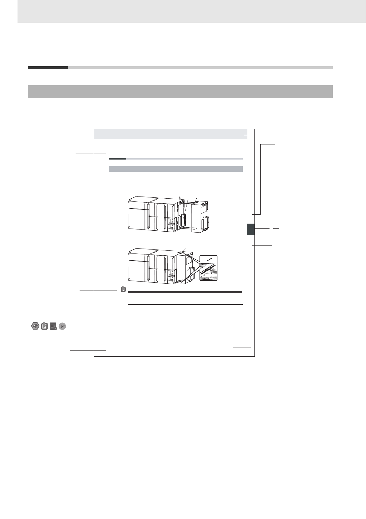
Manual Structure
4-9
4 Installation and Wiring
NJ-series CPU Unit Hardware User’s Manual (W500)
s t i n U g n i t n u o M 3 - 4
4
s t n e n o p m o C r e l l o r t n o C g n i t c e n n o C 1 - 3 - 4
4-3 Mounting Units
The Units that make up an NJ-series Controller can be connected simply by pressing the Units together
and locking the sliders by moving them toward the back of the Units. The End Cover is connected in the
same way to the Unit on the far right side of the Controller.
1 Join the Units so that the connectors fit exactly.
2 The yellow sliders at the top and bottom of each Unit lock the Units together. Move the sliders
toward the back of the Units as shown below until they click into place.
Precautions for Correct Use Precautions for Correct Use
4-3-1 Connecting Controller Components
Connector
Hook
Hook holes
Slider
Lock
Release
Move the sliders toward the back
until they lock into place.
Level 1 heading
Level 2 heading
Level 3 heading
Level 2 heading
A step in a procedure
Manual name
Special information
Level 3 heading
Page tab
Gives the current
headings.
Indicates a procedure.
Icons indicate
precautions, additional
information, or reference
information.
Gives the number
of the main section.
The sliders on the tops and bottoms of the Power Supply Unit, CPU Unit, I/O Units, Special I/O
Units, and CPU Bus Units must be completely locked (until they click into place) after connecting
the adjacent Unit connectors.
Manual Structure
Page Structure
The following page structure is used in this manual.
Note This illustration is provided only as a sample. It may not literally appear in this manual.
8
NX-series NX1P2 CPU Unit Built-in I/O and Option Board User’s Manual (W579)
Page 11

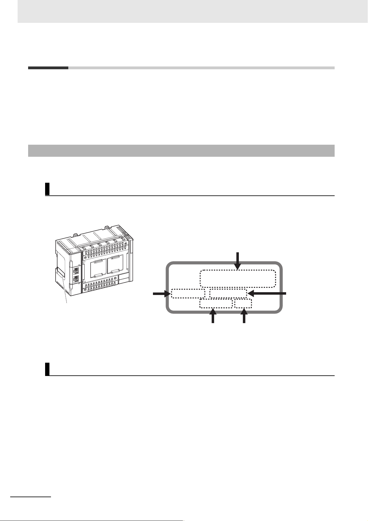
Precautions for Safe Use
Precautions for Correct Use
Additional Information
Version Information
Special Information
Special information in this manual is classified as follows:
Precautions on what to do and what not to do to ensure safe usage of the product.
Precautions on what to do and what not to do to ensure proper operation and performance.
Manual Structure
Additional information to read as required.
This information is provided to increase understanding or make operation easier.
Information on differences in specifications and functionality for CPU Units with different unit
versions and for different versions of the Sysmac Studio is given.
Note References are provided to more detailed or related information.
Precaution on Terminology
In this manual, “download” refers to transferring data from the Sysmac Studio to the physical Controller
and “upload” refers to transferring data from the physical Controller to the Sysmac Studio.
For the Sysmac Studio, synchronization is used to both upload and download data. Here, “synchronize”
means to automatically compare the data for the Sysmac Studio on the computer with the data in the
physical Controller and transfer the data in the direction that is specified by the user.
NX-series NX1P2 CPU Unit Built-in I/O and Option Board User’s Manual (W579)
9
Page 12

Terms and Conditions Agreement
Terms and Conditions Agreement
Warranty, Limitations of Liability
Warranties
Exclusive Warranty
Omron’s exclusive warranty is that the Products will be free from defects in materials and workmanship for a period of twelve months from the date of sale by Omron (or such other period expressed in
writing by Omron). Omron disclaims all other warranties, express or implied.
Limitations
OMRON MAKES NO WARRANTY OR REPRESENTATION, EXPRESS OR IMPLIED, ABOUT
NON-INFRINGEMENT, MERCHANTABILITY OR FITNESS FOR A PARTICULAR PURPOSE OF
THE PRODUCTS. BUYER ACKNOWLEDGES THAT IT ALONE HAS DETERMINED THAT THE
PRODUCTS WILL SUITABLY MEET THE REQUIREMENTS OF THEIR INTENDED USE.
Omron further disclaims all warranties and responsibility of any type for claims or expenses based
on infringement by the Products or otherwise of any intellectual property right.
Buyer Remedy
Omron’s sole obligation hereunder shall be, at Omron’s election, to (i) replace (in the form originally
shipped with Buyer responsible for labor charges for removal or replacement thereof) the non-complying Product, (ii) repair the non-complying Product, or (iii) repay or credit Buyer an amount equal
to the purchase price of the non-complying Product; provided that in no event shall Omron be
responsible for warranty, repair, indemnity or any other claims or expenses regarding the Products
unless Omron’s analysis confirms that the Products were properly handled, stored, installed and
maintained and not subject to contamination, abuse, misuse or inappropriate modification. Return of
any Products by Buyer must be approved in writing by Omron before shipment. Omron Companies
shall not be liable for the suitability or unsuitability or the results from the use of Products in combination with any electrical or electronic components, circuits, system assemblies or any other materials or substances or environments. Any advice, recommendations or information given orally or in
writing, are not to be construed as an amendment or addition to the above warranty.
See http://www.omron.com/global/ or contact your Omron representative for published information.
Limitation on Liability; Etc
OMRON COMPANIES SHALL NOT BE LIABLE FOR SPECIAL, INDIRECT, INCIDENTAL, OR CONSEQUENTIAL DAMAGES, LOSS OF PROFITS OR PRODUCTION OR COMMERCIAL LOSS IN ANY
WAY CONNECTED WITH THE PRODUCTS, WHETHER SUCH CLAIM IS BASED IN CONTRACT,
WARRANTY, NEGLIGENCE OR STRICT LIABILITY.
Further, in no event shall liability of Omron Companies exceed the individual price of the Product on
which liability is asserted.
10
NX-series NX1P2 CPU Unit Built-in I/O and Option Board User’s Manual (W579)
Page 13

Application Considerations
Suitability of Use
Omron Companies shall not be responsible for conformity with any standards, codes or regulations
which apply to the combination of the Product in the Buyer’s application or use of the Product. At
Buyer’s request, Omron will provide applicable third party certification documents identifying ratings
and limitations of use which apply to the Product. This information by itself is not sufficient for a complete determination of the suitability of the Product in combination with the end product, machine, system, or other application or use. Buyer shall be solely responsible for determining appropriateness of
the particular Product with respect to Buyer’s application, product or system. Buyer shall take application responsibility in all cases.
NEVER USE THE PRODUCT FOR AN APPLICATION INVOLVING SERIOUS RISK TO LIFE OR
PROPERTY OR IN LARGE QUANTITIES WITHOUT ENSURING THAT THE SYSTEM AS A WHOLE
HAS BEEN DESIGNED TO ADDRESS THE RISKS, AND THAT THE OMRON PRODUCT(S) IS
PROPERLY RATED AND INSTALLED FOR THE INTENDED USE WITHIN THE OVERALL EQUIPMENT OR SYSTEM.
Terms and Conditions Agreement
Programmable Products
Omron Companies shall not be responsible for the user’s programming of a programmable Product, or
any consequence thereof.
Disclaimers
Performance Data
Data presented in Omron Company websites, catalogs and other materials is provided as a guide for
the user in determining suitability and does not constitute a warranty. It may represent the result of
Omron’s test conditions, and the user must correlate it to actual application requirements. Actual performance is subject to the Omron’s Warranty and Limitations of Liability.
Change in Specifications
Product specifications and accessories may be changed at any time based on improvements and other
reasons. It is our practice to change part numbers when published ratings or features are changed, or
when significant construction changes are made. However, some specifications of the Product may be
changed without any notice. When in doubt, special part numbers may be assigned to fix or establish
key specifications for your application. Please consult with your Omron’s representative at any time to
confirm actual specifications of purchased Product.
Errors and Omissions
Information presented by Omron Companies has been checked and is believed to be accurate; however, no responsibility is assumed for clerical, typographical or proofreading errors or omissions.
NX-series NX1P2 CPU Unit Built-in I/O and Option Board User’s Manual (W579)
11
Page 14

Safety Precautions
Safety Precautions
Refer to the following manuals for safety precautions.
• NX-series NX1P2 CPU Unit Hardware User’s Manual (Cat. No. W578)
12
NX-series NX1P2 CPU Unit Built-in I/O and Option Board User’s Manual (W579)
Page 15

Precautions for Safe Use
Refer to the following manuals for precautions for safe use.
• NX-series NX1P2 CPU Unit Hardware User’s Manual (Cat. No. W578)
Precautions for Safe Use
NX-series NX1P2 CPU Unit Built-in I/O and Option Board User’s Manual (W579)
13
Page 16

Precautions for Correct Use
Precautions for Correct Use
Refer to the following manuals for precautions for correct use.
• NX-series NX1P2 CPU Unit Hardware User’s Manual (Cat. No. W578)
14
NX-series NX1P2 CPU Unit Built-in I/O and Option Board User’s Manual (W579)
Page 17

Regulations and Standards
Refer to the following manuals for regulations and standards.
• NX-series NX1P2 CPU Unit Hardware User’s Manual (Cat. No. W578)
Regulations and Standards
NX-series NX1P2 CPU Unit Built-in I/O and Option Board User’s Manual (W579)
15
Page 18
Versions
PORT1 :
PORT2 :
Ver.1. HW Rev.
LOT No. DDMYY xxxx
ID information indication
Lot number Serial number
Unit version
MAC address
Hardware
revision
Versions
Hardware revisions and unit versions are used to manage the hardware and software in NX-series
Units and EtherCAT slaves.
The hardware revision or unit version is updated each time there is a change in hardware or software
specifications. Even when two Units or EtherCAT slaves have the same model number, they will have
functional or performance differences if they have different hardware revisions or unit versions.
Checking Versions
You can check versions in the ID information indications on the product or with the Sysmac Studio.
Checking Unit Versions on ID Information Indications
The unit version is given on the ID information indication on the side of the product.
The ID information on an NX-series NX1P2- CPU Unit is shown below.
Note The hardware revision is not displayed for the Unit that the hardware revision is in blank.
Checking Unit Versions with the Sysmac Studio
Checking the Unit Version of a Unit
You can use the Production Information while the Sysmac Studio is online to check the unit version
of a Unit.
You can do this for the CPU Unit, NX Units on the CPU Rack, and Option Boards.
Use the following procedure to check the unit version.
1 Right-click CPU Rack under Configurations and Setup - CPU/Expansion Racks in the Multi-
16
view Explorer and select Display Production Information.
The Production Information Dialog Box is displayed.
NX-series NX1P2 CPU Unit Built-in I/O and Option Board User’s Manual (W579)
Page 19
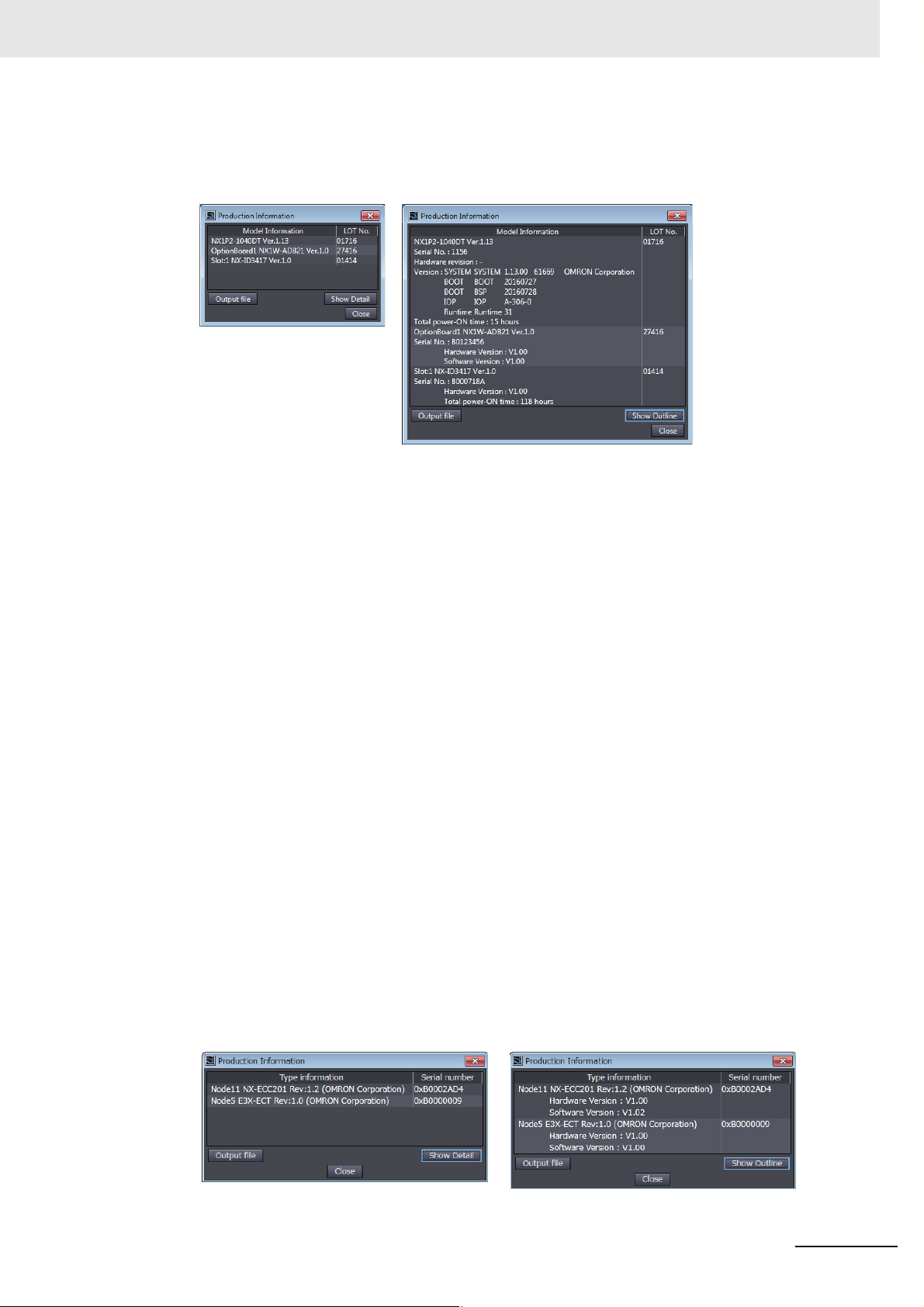
Versions
2 Click the Show Detail or Show Outline Button at the lower right of the Production Information
Dialog Box.
The view will change between the production information details and outline.
Outline View Detail View
The information that is displayed is different for the Outline View and Detail View. The Detail View
displays the unit version, hardware version, and software versions. The Outline View displays only
the unit version.
Note The hardware revision is separated by “/” and displayed on the right of the hardware version. The hard-
ware revision is not displayed for the Unit that the hardware revision is in blank.
Checking the Unit Version of an EtherCAT Slave
You can use the Production Information while the Sysmac Studio is online to check the unit version
of an EtherCAT slave. Use the following procedure to check the unit version.
1 Double-click EtherCAT under Configurations and Setup in the Multiview Explorer. Or,
right-click EtherCAT under Configurations and Setup and select Edit from the menu.
The EtherCAT Tab Page is displayed for the Controller Configurations and Setup Layer.
2 Right-click the master on the EtherCAT Tab Page and select Display Production Information.
The Production Information Dialog Box is displayed.
The unit version is displayed after “Rev.”
Changing Information Displayed in Production Information Dialog Box
1 Click the Show Detail or Show Outline Button at the lower right of the Production Information
Dialog Box.
The view will change between the production information details and outline.
Outline View Detail View
NX-series NX1P2 CPU Unit Built-in I/O and Option Board User’s Manual (W579)
17
Page 20

Versions
Unit Versions of CPU Units and Sysmac Studio Versions
The functions that are supported depend on the unit version of the NX-series CPU Unit. The version of
Sysmac Studio that supports the functions that were added for an upgrade is also required to use those
functions.
Refer to A-1 Version Information on page A-2 for the relationship between the unit versions of the CPU
Units and the Sysmac Studio versions, and for the functions that are supported by each unit version.
18
NX-series NX1P2 CPU Unit Built-in I/O and Option Board User’s Manual (W579)
Page 21

Related Manuals
Related Manuals
The following manuals are related. Use these manuals for reference.
Manual name Cat. No. Model numbers Application Description
NX-series
NX1P2 CPU Unit Hardware User's Manual
NJ/NX-series
CPU Unit Software
User’s Manual
NX-series NX1P2 CPU
Unit Built-in I/O and
Option Board User's
Manual
NJ/NX-series
Instructions Reference
Manual
NJ/NX-series
CPU Unit Motion Control User’s Manual
W578 NX1P2- Learning the basic
specifications of
the NX1P2 CPU
Units, including
introductory information, designing,
installation, and
maintenance.
Mainly hardware
information is provided.
W501 NX701-
NX1P2-
NJ501-
NJ301-
NJ101-
W579 NX1P2- Learning about the
W502 NX701-
NX1P2-
NJ501-
NJ301-
NJ101-
W507 NX701-
NX1P2-
NJ501-
NJ301-
NJ101-
Learning how to
program and set
up an
NJ/NX-series CPU
Unit.
Mainly software
information is provided.
details of functions
only for an
NX-series NX1P2
CPU Unit and an
introduction of
functions for an
NJ/NX-series CPU
Unit.
Learning detailed
specifications on
the basic instructions of an
NJ/NX-series CPU
Unit.
Learning about
motion control settings and programming concepts.
An introduction to the entire NX1P2
system is provided along with the following information on the CPU Unit.
• Features and system configuration
• Introduction
• Part names and functions
• General specifications
• Installation and wiring
• Maintenance and inspection
The following information is provided
on a Controller built with an
NJ/NX-series CPU Unit.
• CPU Unit operation
• CPU Unit features
• Initial settings
• Programming based on IEC
61131-3 language specifications
Of the functions for an NX1P2 CPU
Unit, the following information is provided.
• Built-in I/O
• Serial Communications Option
Boards
• Analog I/O Option Boards
An introduction of following functions
for an NJ/NX-series CPU Unit is also
provided.
• Motion control functions
• EtherNet/IP communications functions
• EtherCAT communications functions
The instructions in the instruction set
(IEC 61131-3 specifications) are
described.
The settings and operation of the CPU
Unit and programming concepts for
motion control are described.
NX-series NX1P2 CPU Unit Built-in I/O and Option Board User’s Manual (W579)
19
Page 22

Related Manuals
Manual name Cat. No. Model numbers Application Description
NJ/NX-series
Motion Control Instructions Reference Manual
NJ/NX-series
CPU Unit Built-in EtherCAT® Port
User’s Manual
NJ/NX-series CPU Unit
Built-in EtherNet/IP™
port User’s Manual
NJ/NX-series
Troubleshooting Manual
Sysmac Studio Version
1 Operation Manual
NX-series
EtherCAT® Coupler
Unit
User’s Manual
NX-series
Data Reference Manual
W508 NX701-
NX1P2-
NJ501-
NJ301-
NJ101-
W505 NX701-
NX1P2-
NJ501-
NJ301-
NJ101-
W506 NX701-
NX1P2-
NJ501-
NJ301-
NJ101-
W503 NX701-
NX1P2-
NJ501-
NJ301-
NJ101-
W504 SYSMAC-
SE2
W519 NX-ECC20 Leaning how to
W525 NX- Referencing lists of
Learning about the
specifications of
the motion control
instructions.
Using the built-in
EtherCAT port on
an NJ/NX-series
CPU Unit.
Using the built-in
EtherNet/IP port
on an
NJ/NX-series CPU
Unit.
Learning about the
errors that may be
detected in an
NJ/NX-series Controller.
Learning about the
operating procedures and functions of the
Sysmac Studio.
use an NX-series
EtherCAT Coupler
Unit and EtherCAT Slave Terminals
the data that is
required to configure systems with
NX-series Units
The motion control instructions are
described.
Information on the built-in EtherCAT
port is provided.
This manual provides an introduction
and provides information on the configuration, features, and setup.
Information on the built-in EtherNet/IP port is provided.
Information is provided on the basic
setup, tag data links, and other features.
Describes concepts on managing
errors that may be detected in an
NJ/NX-series Controller and information on individual errors.
Describes the operating procedures of
the Sysmac Studio.
The following items are described: the
overall system and configuration
methods of an EtherCAT Slave Terminal (which consists of an NX-series
EtherCAT Coupler Unit and NX Units),
and information on hardware, setup,
and functions to set up, control, and
monitor NX Units through EtherCAT.
Lists of the power consumptions,
weights, and other NX Unit data that is
required to configure systems with
NX-series Units are provided.
20
NX-series NX1P2 CPU Unit Built-in I/O and Option Board User’s Manual (W579)
Page 23

Manual name Cat. No. Model numbers Application Description
NX-series NX Units
User’s Manuals
NX-series
Safety Control Unit
User’s Manual
NA-series Programmable Terminal
Software User’s Manual
NS-series Programmable Terminals
Programming Manual
NB-series
Programmable
Terminals NB-Designer
Operation Manual
NB-series
Programmable
Terminals Setup Manual
E5C Digital
Temperature Controllers
Communications
Manual
W521 NX-ID
NX-IA
NX-OC
NX-OD
NX-MD
W522 NX-AD
NX-DA
W566 NX-TS
NX-HB
W523 NX-PD1
NX-PF0
NX-PC0
NX-TBX01
W524 NX-EC0
NX-ECS
NX-PG0
W540 NX-CIF
W565 NX-RS
W567 NX-ILM
Z930
V118 NA5-W Learning about
V073 NS15-
V106 NBQ-TW01B
V107 NBQ-TW01B
H175 E5C Learning about the
NX-SL
NX-SI
NX-SO
NS12-
NS10-
NS8-
NS5-
NBW-TW01B
NBW-TW01B
Learning how to
use NX Units.
Learning how to
use NX-series
Safety Control
Units
NA-series PT
pages and object
functions.
Learning how to
use the NS-series
Programmable
Terminals.
Learning about the
screens and object
functions of
NB-series Programmable Terminals.
Learning the specifications and settings required to
install an
NB-series Programmable Terminal and connect
peripheral devices.
communications
functions of E5C
Digital Temperature Controllers
Describes the hardware, setup methods, and functions of the NX Units.
Manuals are available for the following Units.
Digital I/O Units, Analog I/O Units,
System Units, Position Interface Units,
Communications Interface Units, Load
Cell Input Units, and IO-Link Master
Units.
The hardware, setup methods, and
functions of the NX-series Safety
Control Unit are described.
Describes the pages and object functions of the NA-series Programmable
Terminals.
Describes the setup methods, functions, etc. of the NS-series Programmable Terminals.
Describes the screens and object
functions of NB-series Programmable
Terminals.
The procedure for installing the
NB-Designer, an overview of managing the screen data of NB-series Programmable Terminals with the
NBManager, and information on maintenance after operation and troubleshooting are also provided.
Information is provided on NB-series
Programmable Terminal specifications, part names, installation procedures, procedures to connect an
NB-series Programmable Terminal to
peripheral devices, and settings
required after connection to start communications and operations.
Provides an overview of the communications method, communications
specifications, and wiring of E5C
Digital Temperature Controllers.
Related Manuals
NX-series NX1P2 CPU Unit Built-in I/O and Option Board User’s Manual (W579)
21
Page 24

Related Manuals
Manual name Cat. No. Model numbers Application Description
E5C Digital
Temperature Controllers
User’s Manual
H174 E5C Learning about the
functions of E5C
Digital Temperature Controllers
Describes how to use E5C Digital
Temperature Controllers.
22
NX-series NX1P2 CPU Unit Built-in I/O and Option Board User’s Manual (W579)
Page 25

Terminology
Terminology
Term Description
absolute encoder home offsets
array specification One of the variable specifications. An array variable contains multiple elements of
AT One of the attributes of a variable.
axes groups A functional unit that groups together axes within the Motion Control Function Mod-
Axes Group Variable A system-defined variable that is defined as a structure and provides status infor-
axis A functional unit within the Motion Control Function Module. An axis is assigned to
Axis Variable A system-defined variable that is defined as a structure and provides status infor-
basic data type Any of the data types that are defined by IEC 61131-3.
cam data variable A variable that represents the cam data as a structure array.
CJ-series Unit Any of the CJ-series Units that can be used with an NJ-series Controller.
Communications Coupler Unit The generic name of an interface unit for remote I/O communications on a network
Constant One of the attributes of a variable.
Controller The range of devices that are directly controlled by the CPU Unit.
Controller error Errors that are defined by the NJ/NX-series System.
Controller event One of the events in the NJ/NX-series System. Controller events are errors and
Controller information Information that is defined by the NJ/NX-series System that is not an error. It rep-
This data is used to restore in the CPU Unit the actual position of a Servo D rive with
an absolute encoder. The offset is the difference between the command position
after homing and the absolute data that is read from the absolute encoder.
the same data type. The elements in the array are specified by serial numbers
called subscripts that start from the beginning of the array.
This attribute allows the user to specify what is assigned to a variable. An I/O port
or an address in memory used for CJ-series Units can be specified.
ule.
mation and some of the axes parameters for an individual axes group.
An Axes Group Variable is used to specify an axes group for motion control instructions and to monitor the command interpolation velocity, error information, and
other information for the axes group.
the drive mechanism in an external Servo Drive or the sensing mechanism in an
external Encoder Input Slave Unit.
mation and some of the axis parameters for an individual axis.
An Axis Variable is used to specify an axis for motion control instructions and to
monitor the command position, error information, and other information for the axis.
They include Boolean, bit string, integer, real, duration, date, time of day, date and
time, and text string data types.
“Basic data type” is used as opposed to derivative data types, which are defined by
the user.
A cam data variable is an array structure that consists of phases and displacements.
between NX Units and a host network master. For example, an EtherCAT Coupler
Unit is a Communications Coupler Unit for an EtherCAT network.
If you specify the Constant attribute for a variable, the value of the variable cannot
be written by any instructions, ST operators, or CIP message communications.
In the NX-series System, the Con
slaves (including general-purpose slaves and Servo Drives).
In the NJ-series System, the Controller includes the CPU Rack, Expansion Racks,
and EtherCAT slaves (including general-purpose slaves and Servo Drives).
“Controller error” is a collective term for major fault level, partial fault level, minor
fault level, and observation Controller events.
information that are defined by the system for user notification. A Controller event
occurs when the system detects a factor that is defined as a Controller event.
resents an information Controller event.
t
roller includes the CPU Rack and EtherCAT
NX-series NX1P2 CPU Unit Built-in I/O and Option Board User’s Manual (W579)
23
Page 26

Terminology
Term Description
CPU Unit The Unit that serves as the center of control for a Machine Automation Controller.
The CPU Unit executes tasks, refreshes I/O for other Units and slaves, etc. The
NJ/NX-series CPU Units include NX701-, NX1P2-, NJ501-,
and NJ301-.
derivative data type A data type that is defined by the user. Structures, unions, and enumerations are
derivative data types.
device A general term for any Unit or slave that is refreshed by the I/O refreshing that is
performed by the CPU Unit. Specifically, it refers to EtherCAT slaves, NX Units on
the CPU Unit, built-in I/O, Option Boards, and CJ-series Units.
device output An output for any Unit or slave that is refreshed by the I/O refreshing that is per-
formed by the CPU Unit.
device variable A variable that is used to access a specific device through an I/O port.
download To transfer data from the Sysmac Studio to the Controller with the synchronization
operation of the Sysmac Studio.
edge One of the attributes of a variable.
This attribute makes a BOOL variable pass TRUE to a function block when the vari-
able changes from FALSE to TRUE or when it changes from TRUE to FALSE.
enumeration One of the derivative data types. This data type takes one item from a prepared
name list of enumerators as its value.
enumerator One of the values that an enumeration can take expressed as a character string.
The value of an enumeration is one of the enumerators.
EtherCAT Master Function Module One of the function modules. This function module controls the EtherCAT slaves as
the EtherCAT master.
EtherNet/IP Function Module One of the function modules. This function module controls the built-in EtherNet/IP
port.
event log A function that recognizes and records errors and other events.
Event Setup Settings that define user-defined errors and user-defined information.
event task A task that executes a user program only once when the task execution conditions
are met.
FB An acronym for “function block.”
forced refreshing Forcing the refreshing of an input from an external device or an output to an exter-
nal device, e.g., when the user debugs a program.
Addresses that are subject to forced refreshing can still be overwritten from the
user program.
FUN An abbreviation for “function.”
function A POU that is used to create an object that determines a unique output for the
same input, such as for data processing.
function block A POU that is used to create an object that can have a different output for the same
input, such as for a timer or counter.
function module One of the functional units of the software configuration of the CPU Unit.
g
ene
ral-purpose slave Any of the EtherCAT slaves that cannot be assigned to an axis.
global variable A variable that can be read or written from all POUs (programs, functions, and func-
tion blocks).
I/O map settings Settings that assign variables to I/O ports. Assignment information between I/O
ports and variables.
I/O port A logical interface that is used by the CPU Unit to exchange data with an external
device (slave or Unit).
I/O refreshing
information One of the event levels for Controller events or user-defined events. These are not
Cyclic data exchange with external devices that is performed with predetermined
memory addresses.
errors, but appear in the event log to notify the user of specific information.
24
NX-series NX1P2 CPU Unit Built-in I/O and Option Board User’s Manual (W579)
Page 27

Terminology
Term Description
Initial Value One of the attributes of a variable. The variable is set to the initial value in the fol-
lowing situations.
• When power is turned ON
• When the CPU Unit changes to RUN mode
• When you specify to initialize the values when the user program is transferred
• When a major fault level Controller error occurs
inline ST ST programming that is included within a ladder diagram program.
instruction The smallest unit of the processing elements that are provided by OMRON for use
in POU algorithms. There are ladder diagram instructions (program inputs and out-
puts), function instructions, function block instructions, and ST statements.
literal A constant expression that is used in a user program.
local variable A variable that can be accessed only from inside the POU in which it is defined.
“Local variable” is used as opposed to “global variable.”
Local variables include internal variables, input variables, output variables, in-out
variables, and external variables.
main memory The memory inside the CPU Unit that is used by the CPU Unit to execute the OS
and user program.
major fault level Controller error
MC Test Run A function to check motor operation and wiring from the Sysmac Studio.
memory used for CJ-series Units One type of I/O memory in an NX1P2 CPU Unit and NJ-series CPU Unit. It contains
minor fault level Controller error An error for which part of the control operations for one of the function modules in
Motion Control Function Module One of the function modules. The MC Function Module performs motion control
motion control instruction A function block instruction that executes motion control.
namespace A system that is used to group and nest the names of functions, function block defi-
Network Publish One of the attributes of a variable.
NX bus The NX-series internal bus. An NX1P2 CPU Unit has the NX bus.
NX Units
observation One of the event levels for Controller events or user-defined events.
partial fault level Controller error An error for which all of the control operations for one of the function modules in the
PDO communications
An error for which all NJ/NX-series Controller control operations stop. The CPU Unit
immediately stops user program execution and turns OFF the loads for all slaves and
Units (including remote I/O).
addresses that can be directly specified by the user.
It can be accessed only with variables with an AT attribute. This memory is used to
access CJ-series Units and CJ-series networks. However, you cannot connect the
CJ-series Units to the NX1P2 CPU Units.
the NJ/NX-series Controller stop.
The NJ/NX-series CPU Unit continues operation even after a minor fault level Con-
troller error occurs.
based on commands from the motion control instructions that are executed in the
user program.
The Motion Control Function Module supports instructions that are based on func-
tion blocks for PLCopen
cally for the Motion Control Function Module.
nitions, and data types.
This attribute allows you to use CIP message communications or tag data links to
read/write variables from another Controller or from a host computer.
Any of the NX-series Units that perform I/O processing with connected external
devices. The Communications Coupler Units are not included with the NX Units.
These are minor errors that do not affect control operations, but appear in the event
log to notify the user of specific information.
NJ/NX-series Controller stop.
An NJ/NX-series CPU Unit continues operation even after a partial fault level Con-
troller error.
An abbreviation for process data communications. Data is exchanged between the
master and slaves on a process data communications cycle. (The process data com-
munications cycle is the same as the task period of the primary periodic task.)
®
motion control as well as instructions developed specifi-
NX-series NX1P2 CPU Unit Built-in I/O and Option Board User’s Manual (W579)
25
Page 28

Terminology
Term Description
periodic task A task for which user program execution and I/O refreshing are performed each
period.
PLC Function Module One of the function modules. This function module executes the user program,
sends commands to the Motion Control Function Module, and provides an interface
to the USB and SD Memory Card.
POU An acronym for “program organization unit.” A POU is a unit in a program execution
model that is defined in IEC 61131-3.
A POU contains an algorithm and a local variable table and forms the basic unit
used to build a user program.
There are three types of POUs: programs, functions, and function blocks.
primary periodic task The task with the highest priority.
process data communications One type of EtherCAT communications in which process data objects (PDOs) are
used to exchange information cyclically and in realtime. Process data communica-
tions are also called PDO communications.
program Along with functions and function blocks, one of the three types of POUs.
Programs are assigned to tasks to execute them.
Range Specification One of the variable specifications. You can specify a range for a variable in
advance. The variable can take only values that are in the specified range.
Retain One of the attributes of a variable. The values of variables with a Retain attribute
are held at the following times. (Variables without a Retain attribute are set to their
initial values.)
• When power is turned ON after power interruption
• When the CPU Unit changes to RUN mode
• When you specify to not initialize the values when the user program is transferred
SDO communications One type of EtherCAT communications in which service data objects (SDOs) are
used to transmit information whenever required.
Servo Drive/encoder input slave Any of the EtherCAT slaves that is assigned to an axis. In the NJ/NX-series Sys-
tem, it would be a Servo Drive or Encoder Input Slave Unit.
slave A device that performs remote I/O for a master.
slave and Unit configurations A generic term for the EtherCAT configuration and Unit configuration.
Slave Terminal A building-block remote I/O terminal to which a Communications Coupler Unit and
NX Units are mounted. A Slave Terminal is one type of slave.
Special Unit Setup A generic term for the settings for a Special Unit, including the settings in allocated
DM Area words.
structure One of the derivative data types. It consists of multiple data types placed together
into a layered structure.
synchronization A function that automatically compares the information in the NJ/NX-series Control-
ler with the information in the Sysmac Studio, displays any differences and loca-
tions in a hierarchical form, and can be used to synchronize the information.
Sysmac Studio A computer software application for setting, programming, debugging, and trouble-
shooting NJ/NX-series Controllers. It also provides operations for motion control
and a Simulator.
system common processing System processing that is performed by the CPU Unit to perform I/O refreshing and
the user prog
tasks, data trace processing, and other processing is performed.
system service Processing that is performed by the CPU Unit in unused time between task pro-
cessing. The system service includes communications processing, SD Memory
Card access processing, self-diagnosis processing, and other processing.
system-defined variable A variable for which all attributes are defined by the system and cannot be changed
by the user.
task An attribute that defines when a program is executed.
task period The interval at which the primary periodic task or a periodic task is executed.
union One of the derivative data types. It allows you to handle the same data as different
data types.
Unit A device that mounts to the CPU Rack or an Expansion Rack.
am execution within a task. Exclusive control of variables between
r
26
NX-series NX1P2 CPU Unit Built-in I/O and Option Board User’s Manual (W579)
Page 29

Terminology
Term Description
Unit configuration The configuration information for the Units that are set on the Sysmac Studio. This
information tells what Unit models are connected to the CPU Unit and where they
are connected.
upload To transfer data from the Controller to the Sysmac Studio with the synchronization
operation of the Sysmac Studio.
user program All of the programs in one project.
user-defined event One of the events in the NJ/NX-series System. These events are defined by the
user. “User-defined events” is a generic term for user-defined errors and
user-defined information.
user-defined variable A variable for which all of the attributes are defined by the user and can be changed
by the user.
variable A representation of data, such as a numeric value or character string, that is used in
a user program.
You can change the value of a variable by assigned the required value. “Variable” is
used as opposed to “constant,” for which the value does not change.
variable memory A memory area that contains the present values of variables that do not have AT
specifications. It can be accessed only with variables without an AT attribute.
NX-series NX1P2 CPU Unit Built-in I/O and Option Board User’s Manual (W579)
27
Page 30

Revision History
W579-E1-04
Revision code
Cat. No.
Revision History
A manual revision code appears as a suffix to the catalog number on the front and back covers of the
manual.
Revision
code
01 October 2016 Original production
02 January 2017 Corrected mistakes.
03 October 2017 Added shipbuilding standards (LR).
04 January 2019
Date Revised content
Made changes accompanying the transfer of explanation for event codes and
errors to the NJ/NX-series Troubleshooting Manual.
28
NX-series NX1P2 CPU Unit Built-in I/O and Option Board User’s Manual (W579)
Page 31

1A
2I
3
4
5
6
7
8
9
Appendices
Built-in I/O
Option Boards
Index
Serial Communications
Analog I/O
Introduction of Motion Control Functions
Introduction of EtherNet/IP Communications
Functions
Introduction of EtherCAT Communications Functions
Troubleshooting
2
3
4
5
8
9
6
7
1A
I
Introduction to NX1P2
CPU Units
Sections in this Manual
Sections in this Manual
NX-series NX1P2 CPU Unit Built-in I/O and Option Board User’s Manual (W579)
29
Page 32

Sections in this Manual
30
NX-series NX1P2 CPU Unit Built-in I/O and Option Board User’s Manual (W579)
Page 33

Introduction to NX1P2 CPU Units
This section describes the specifications and operating procedure of the NX1P2 CPU
Units.
1-1 Function Specifications for NX1P2 CPU Units . . . . . . . . . . . . . . . . . . . . . . 1-2
1-2 Overall Operating Procedure . . . . . . . . . . . . . . . . . . . . . . . . . . . . . . . . . . . . 1-7
1-2-1 Overall Operating Procedure . . . . . . . . . . . . . . . . . . . . . . . . . . . . . . . . . . . . . 1-7
1-2-2 Procedure Details . . . . . . . . . . . . . . . . . . . . . . . . . . . . . . . . . . . . . . . . . . . . . . 1-8
1
NX-series NX1P2 CPU Unit Built-in I/O and Option Board User’s Manual (W579)
1 - 1
Page 34

1 Introduction to NX1P2 CPU Units
1-1 Function Specifications for NX1P2
CPU Units
This following table gives the main specifications of the NX1P2 CPU Units.
NX1P2-
*3
*3
*4
*4
Processing time
Programming
Item
Instruction
execution
times
Program
capacity
Memory
capacity for
variables
Data types Number of data types 1,000
Memory for
CJ-series
Units (Can be
specified with
AT specifications for variables.)
*1
LD instruction 3.3 ns
Math instructions (for long real
data)
Size 1.5 MB
Number of POU
definitions
Number of POU
instances
Size 32 KB
Number of vari-
ables
Size 2 MB
Number of variables
*2
Quantity
Retain attributes
No Retain
attributes
CIO Area
Work Area
Holding Area
DM Area
EM Area
11 10 90
70 ns or more
450
1,800
5,000
90,000
0 to 6,144 words (CIO 0 to CIO 6,143)
0 to 512 words (W0 to W511)
0 to 1,536 words (H0 to H1,535)
0 to 16,000 words (D0 to D15,999)
---
1 - 2
NX-series NX1P2 CPU Unit Built-in I/O and Option Board User’s Manual (W579)
Page 35

1 Introduction to NX1P2 CPU Units
1-1 Function Specifications for
Motion
control
Item
Maximum number of controlled
axes
Motion control
axes
Single-axis position control axes
Maximum number of used real
Number of
controlled
*5
axes
Maximum number of axes groups 8 axes groups ---
Motion control period Same as the period for primary periodic task
Cams
Position units Pulse, mm, μm, nm, degree, and inch
Override Factors 0.00% or 0.01% to 500.00%
axes
Used motion
control servo
axes
Used single-axis
position control
servo axes
Maximum number of axes for linear interpolation axis control
Number of axes for circular interpolation axis control
Number of
cam data
points
Maximum number of cam tables 80 tables ---
Maximum points
per cam table
Maximum points
for all cam tables
11 10 90
12 axes 10 axes 4 axes
8 axes 6 axes ---
4 axes
8 axes 6 axes 4 axes
4 axes 2 axes ---
4 axes
4 axes per axes group ---
2 axes per axes group ---
65,535 points ---
262,140 points ---
NX1P2-
NX1P2 CPU Units
1
NX-series NX1P2 CPU Unit Built-in I/O and Option Board User’s Manual (W579)
1 - 3
Page 36

1 Introduction to NX1P2 CPU Units
Built-in
EtherNet/IP
port
Item
11 10 90
NX1P2-
Number of ports 1
Physical layer 10BASE-T/100BASE-TX
Frame length 1,514 bytes max.
Media access method CSMA/CD
Modulation Baseband
Topology Star
Baud rate 100 Mbps (100BASE-TX)
Transmission media
Maximum transmission distance between Ether-
STP (shielded twisted-pair) cable of Ethernet category
5, 5e, or higher
100 m
net switch and node
Maximum number of cascade connections There are no restrictions if an Ethernet switch is used.
Maximum number of connec-
32
tions
Packet interval
*6
Permissible communications
Can be set for each connection.
2 to 10,000 ms in 1-ms increments
3,000 pps
*7
(including heartbeat)
band
Maximum number of tag sets 32
Tag ty pes Network variables, CIO, Work, Holding and DM Areas
CIP service:
Tag data links
(cyclic communications)
Number of tags per connection
(= 1 tag set)
Maximum number of tags 256
Maximum link data size per node
8 (7 tags if Controller status is included in the tag set.)
19,200 bytes
(total size for all tags)
Maximum data size per connec-
600 bytes
tion
Maximum number of registrable
32 (1 connection = 1 tag set)
tag sets
Maximum tag set size
Multi-cast packet filter
*8
600 bytes (Two bytes are used if Controller status is
included in the tag set.)
Supported
Class 3 (number of connections) 32 (clients plus server)
Maximum num-
32
ber of c li en ts t ha t
CIP message
service:
Explicit messages
UCMM
(non-connection type)
can communi-
cate at one time
Maximum num-
ber of servers
32
that can commu-
nicate at one
time
Number of TCP sockets 30
1 - 4
NX-series NX1P2 CPU Unit Built-in I/O and Option Board User’s Manual (W579)
Page 37

1 Introduction to NX1P2 CPU Units
1-1 Function Specifications for
Built-in
EtherCAT port
Serial
communications
(Serial
Communications
Option
Board)
Unit configuration
Option
Board
Built-in
I/O
Internal
clock
Item
Communications standard IEC 61158 Type12
EtherCAT master specifications Class B (Feature Pack Motion Control compliant)
Physical layer 100BASE-TX
Modulation Baseband
Baud rate 100 Mbps (100BASE-TX)
Duplex mode Auto
Topology Line, daisy chain, and branching
Transmission media
Maximum transmission distance between nodes 100 m
Maximum number of slaves 16
Range of node addresses that can be set 1 to 192
Maximum process data size
Maximum process data size per slave
Communications cycle 2,000 to 8,000 μs (in 250-μs increments)
Sync jitter 1 μs max.
Communications method Half duplex
Synchronization Start-stop
Baud rate 1.2/2.4/4.8/9.6/19.2/38.4/57.6/115.2 kbps
Transmission distance Depends on Option Board.
Supported protocol
Maximum
number of
connectable
Units
Power supply
Number of slots
Input Number of points 24 24 14
Output
Accuracy
Retention time of built-in capacitor At ambient temperature of 40°C: 10 days
Maximum number of NX Units
per CPU Rack
Maximum number of NX Units for
entire controller
Model
Power OFF detection time 2 to 8 ms
Number of points 16 16 10
Load-short circuit protection
Pulse output Not provided
11 10 90
Twisted-pair cable of category 5 or higher (double-shielded straight cable with aluminum tape and
braiding)
Input: 1,434 bytes
Output: 1,434 bytes
However, the maximum number of process data frames
is 1.
Input: 1,434 bytes
Output: 1,434 bytes
Host link (FINS), Modbus-RTU master, and no-protocol
8
24
On CPU Rack: 8
On EtherCAT Slave Terminals: 16
A non-isolated power supply for DC input is built into the
CPU Unit.
221
11/10/90: Not provided (NPN)
111/101/901: Provided (PNP)
At ambient temperature of 55°C: -3.5 to 0.5 min error
per month
At ambient temperature of 25°C: -1.5 to 1.5 min error
per month
At ambient temperature of 0°C: -3 to 1 min error per
month
NX1P2-
NX1P2 CPU Units
1
NX-series NX1P2 CPU Unit Built-in I/O and Option Board User’s Manual (W579)
1 - 5
Page 38

1 Introduction to NX1P2 CPU Units
*1. Execution objects and variable tables (including variable names)
*2. Memory used for CJ-series Units is included.
*3. The value can be set in 1-word increments. The value is included in the total size of variables without Retain attributes.
*4. The value can be set in 1-word increments. The value is included in the total size of variables with Retain attributes.
*5. For details on each axis, refer to the NJ/NX-series CPU Unit Motion Control User’s Manual (Cat. No. W507).
*6. Data will be refreshed at the set interval, regardless of the number of nodes.
*7. “pps” means packets per second, i.e., the number of communications packets that can be sent or received in one second.
*8. As the EtherNet/IP port implements the IGMP client, unnecessary multi-cast packets can be filtered by using an Ethernet
switch that supports IGMP Snooping.
1 - 6
NX-series NX1P2 CPU Unit Built-in I/O and Option Board User’s Manual (W579)
Page 39

1 Introduction to NX1P2 CPU Units
1-2 Overall Operating Procedure
The overall operating procedure of the NX1P2 CPU Units is shown below, with each step of the procedure described in detail.
1-2 Overall Operating Procedure
1-2-1 Overall Operating Procedure
The overall procedure to use an NX1P2 CPU Unit is given below.
Step 1. Software Design
Design the overall system configuration, task configuration, programs,
and variables.
Step 1-1 Designing I/O and Processing
Step 1-2 Designing Tasks
Step 1-3 Designing Programs
Step 2. Software Setup and Programming
Create the system configuration that you designed in step 1 with the
Support Software and assign the variables. Create the tasks and programs, and debug them, e.g., with simulations.
Step 2-1 Slave and NX Unit Configurations
Step 2-2 Controller Setup
Step 2-3 Programming
Step 2-4 Offline Debugging
1
1-2-1 Overall Operating Procedure
Step 3. Mounting and Setting Hardware
Mount the Units and make the required hardware settings.
Step 4. Wiring
Connect the network cables and wire the I/O.
Step 5. Checking Operation and Starting Operation
on the Actual System
Connect the Support Software to the physical system and download the
project. Check operation on the physical system and then start actual
system operation.
NX-series NX1P2 CPU Unit Built-in I/O and Option Board User’s Manual (W579)
1 - 7
Page 40

1 Introduction to NX1P2 CPU Units
1-2-2 Procedure Details
Step 1. Software Design
Step Description Reference
Step 1-1
Designing I/O and Processing
• External I/O devices and unit configuration
• Refresh periods for external devices
• Program contents
NX-series NX1P2 CPU Unit
Hardware User’s Manual
(Cat. No. W578)
Step 1-2
Designing Tasks
Step 1-3
Designing Programs
POU (Program Organization Unit) Design
Variable Design • Defining variables that you can use in more than one POU and
• Task configuration
• Relationship between tasks and programs
• Task periods
• Slave, NX Unit, and built-in I/O refresh times
• Exclusive control methods for variables between tasks
• Programs
• Functions and function blocks
• Determining the algorithm languages
variables that you use in only specific POUs
• Defining the variables names for the device variables that you
use to access slaves, NX Units, and the built-in I/O
• Defining the attributes of variables, such as the Name and
Retain attributes
• Designing the data types of variables
Step 2. Software Setup and Programming
Step Description Sysmac Studio
Operations
Project Creation 1. Create a project in the Sysmac
Studio.
2. Insert a Controller.
New Project Button
Insert - Controller
NJ/NX-series CPU Unit Software User’s Manual (Cat.
No. W501)
NJ/NX-series CPU Unit Software User’s Manual (Cat.
No. W501)
NJ/NX-series CPU Unit Software User’s Manual (Cat.
No. W501)
Reference
Sysmac Studio Version 1
Operation Manual (Cat. No.
W504)
The following Controller Configurations and Setup and the Programming and Task Settings can be performed in either
order.
Step 2-1
Slave and NX Unit Configurations
1. Creating the Slave
and NX Unit Configurations
1 - 8
1. Creating the slave configuration and
NX Unit configuration either offline or
online. (For online configuration,
make the online connection that is
described in step 5.)
2. Setting up any Slave Terminals that
are used.
NX-series NX1P2 CPU Unit Built-in I/O and Option Board User’s Manual (W579)
EtherCAT Tab Page
CPU and Expansion
Racks Tab Page
Slave Terminal Tab
Page
NJ/NX-series CPU Unit Software User’s Manual (Cat.
No. W501)
NX-series EtherCAT Coupler
Units User’s Manual (Cat.
No. W519)
Page 41

1 Introduction to NX1P2 CPU Units
1-2 Overall Operating Procedure
2. Assigning Device
Variables to I/O Ports
(The following step is for motion control.)
3. Creating the Axes
and Assigning Them to
the Servo
Drive/Encoder Input
Slaves
Step 2-2
Controller Setup
Registering device variables in the variable table
(Variable names are user-defined or
automatically created.)
Creating the axes and setting them as
real axes or virtual axes.
Creating axes groups to perform interpolated axes control.
Setting the following parameters from the
Sysmac Studio
Setting the initial values for the PLC
Function Module
(When battery is used)Setting the
clock data with the clock function
Setting the initial values for the NX
Bus Function Module
(The following step is for motion
control.)
Setting the initial settings for the
Motion Control Function Module
Setting the initial values for the EtherCAT Function Module
Setting the initial values for the EtherNet/IP Function Module
Setting the initial values for the
built-in I/O
Setting the initial values for an
Option Board
I/O Map NJ/NX-series CPU Unit Soft-
ware User’s Manual (Cat.
No. W501)
Configurations and
Setup − Motion
Control Setup
Configurations and
Setup − Controller
Setup − Operation
Settings
Controller − Controller Clock
Configurations and
Setup −
CPU/Expansion
Racks − CPU Rack
Configurations and
Setup − Motion
Control Setup
Configurations and
Setup − EtherCAT
Configurations and
Setup − Controller
Setup − Built-in
EtherNet/IP Port
Settings
Configurations and
Setup − Controller
Setup − Built-in I/O
Settings
Configurations and
Setup − Controller
Setup − Option
Board Settings
NJ/NX-series CPU Unit Software User’s Manual (Cat.
No. W501)
NJ/NX-series CPU Unit Software User’s Manual (Cat.
No. W501)
2-4-1 Built-in I/O Settings on
page 2-8
3-2-1 Settings on page 3-4
1
1-2-2 Procedure Details
Step 2-3
Programming
NX-series NX1P2 CPU Unit Built-in I/O and Option Board User’s Manual (W579)
1 - 9
Page 42

1 Introduction to NX1P2 CPU Units
1. Registering Variables
2. Writing Algorithms
for POUs
3. Setting the Tasks Making task settings Configurations and
Step 2-4
Offline Debugging
• Registering the variables used by more
than one POU in the global variable
table with Sysmac Studio
• Registering the local variable table for
each program
• Registering the local variable table for
each function block and function
Writing the algorithms for the POUs (programs, function blocks, and functions) in
the required languages
Checking the algorithms and task execution times on the Simulator (virtual controller)
Global Variable
Table Editor
Local Variable Table
Editor
Programming Editor NJ/NX-series CPU Unit Soft-
Setup − Task Settings
Sysmac Studio Version 1
Operation Manual (Cat. No.
W504)
NJ/NX-series CPU Unit Software User’s Manual (Cat.
No. W501)
ware User’s Manual (Cat.
No. W501)
NJ/NX-series Instructions
Reference Manual (Cat. No.
W502)
NJ/NX-series Motion Control
Instructions Reference Manual (Cat. No. W508)
NJ/NX-series CPU Unit Software User’s Manual (Cat.
No. W501)
NJ/NX-series CPU Unit Software User’s Manual (Cat.
No. W501)
Step 3. Mounting and Setting Hardware
Step Description Reference
1. Mounting • Connecting adjacent Units
• Mounting to DIN Track
2. Setting Hardware • Setting the node addresses of the EtherCAT slaves Operation manuals for the
NX-series NX1P2 CPU Unit
Hardware User’s Manual
(Cat. No. W578)
EtherCAT slaves
Step 4. Wiring
Step Description Reference
1. Connecting the
Power Supply to the
CPU Unit
2. Connecting Ethernet Cable
• Connecting the power supply and ground wires NX-series NX1P2 CPU Unit
Hardware User’s Manual
(Cat. No. W578)
• Connecting the built-in EtherCAT port
• Connecting the built-in EtherNet/IP port
NJ/NX-series CPU Unit
Built-in EtherCAT Port User’s
Manual (Cat. No. W505)
NJ/NX-series CPU Unit
Built-in EtherNet/IP Port
User’s Manual (Cat. No.
W506)
1 - 10
NX-series NX1P2 CPU Unit Built-in I/O and Option Board User’s Manual (W579)
Page 43

1 Introduction to NX1P2 CPU Units
1-2 Overall Operating Procedure
3. Wiring I/O • Wiring the built-in I/O
• Wiring I/O for NX Units
• Wiring Option Boards
• Wiring I/O to EtherCAT slaves Operation manuals for the
• Checking wiring Sysmac Studio Version 1
4. Connecting the
Computer That Runs
the Sysmac Studio
• Connecting the built-in EtherNet/IP port Sysmac Studio Version 1
NX-series NX1P2 CPU Unit
Hardware User’s Manual
(Cat. No. W578)
Manuals for the specific NX
Units
EtherCAT slaves
NX-series NX1P2 CPU Unit
Hardware User’s Manual
(Cat. No. W578)
Operation Manual (Cat. No.
W504)
Operation Manual (Cat. No.
W504)
Step 5. Checking Operation and Starting Operation on the Actual System
Step Description Sysmac Studio
Operations
1. Online Connection
to Sysmac Studio and
Project Download
Turn ON the power supply to the Controller and place the Sysmac Studio online.
Then, download the project.
Perform this step before you create the
slave configuration or Unit configuration
from the mounted Units in step 2-1.
*1
Controller − Communications Setup
Controller − Synchronization
Reference
NJ/NX-series CPU Unit Software User’s Manual (Cat.
No. W501)
1
1-2-2 Procedure Details
2. Operation Check on
Controller
3. Actual Controller
Operation
*1. Use the Synchronize Menu of the Sysmac Studio to download the project.
1. Check the wiring by using forced
refreshing of real I/O from the I/O Map
or Watch Tab Page.
2. For motion control, use the MC Test
Run operations in PROGRAM mode
to check the wiring. Then check the
motor rotation directions for jogging,
travel distances for relative
positioning (e.g., for electronic gear
settings), and homing operation.
3. Change the Controller to RUN mode
and check the operation of the user
program.
Start actual operation.
--- NJ/NX-series CPU Unit Soft-
--- ---
ware User’s Manual (Cat.
No. W501)
NX-series NX1P2 CPU Unit Built-in I/O and Option Board User’s Manual (W579)
1 - 11
Page 44

1 Introduction to NX1P2 CPU Units
1 - 12
NX-series NX1P2 CPU Unit Built-in I/O and Option Board User’s Manual (W579)
Page 45

Built-in I/O
This section describes the built-in I/O of the NX1P2 CPU Units.
2-1 Built-in I/O Terminal Allocation . . . . . . . . . . . . . . . . . . . . . . . . . . . . . . . . . . . 2-2
2-1-1 Terminal Arrangement . . . . . . . . . . . . . . . . . . . . . . . . . . . . . . . . . . . . . . . . . . 2-2
2-2 I/O Data Specifications . . . . . . . . . . . . . . . . . . . . . . . . . . . . . . . . . . . . . . . . . 2-5
2-2-1 NX1P2-24DT/-24DT1 . . . . . . . . . . . . . . . . . . . . . . . . . . . . . . . . . . . . 2-5
2-2-2 NX1P2-40DT/-40DT1 . . . . . . . . . . . . . . . . . . . . . . . . . . . . . . . . . . . . 2-6
2-3 Built-in I/O Functions . . . . . . . . . . . . . . . . . . . . . . . . . . . . . . . . . . . . . . . . . . . 2-7
2-4 Settings . . . . . . . . . . . . . . . . . . . . . . . . . . . . . . . . . . . . . . . . . . . . . . . . . . . . . . 2-8
2-4-1 Built-in I/O Settings . . . . . . . . . . . . . . . . . . . . . . . . . . . . . . . . . . . . . . . . . . . . . 2-8
2-4-2 I/O Map . . . . . . . . . . . . . . . . . . . . . . . . . . . . . . . . . . . . . . . . . . . . . . . . . . . . . . 2-9
2-5 Functions . . . . . . . . . . . . . . . . . . . . . . . . . . . . . . . . . . . . . . . . . . . . . . . . . . . 2-10
2-5-1 Input Filter . . . . . . . . . . . . . . . . . . . . . . . . . . . . . . . . . . . . . . . . . . . . . . . . . . . 2-10
2-5-2 Output Load Rejection Setting . . . . . . . . . . . . . . . . . . . . . . . . . . . . . . . . . . . 2-12
2-6 I/O Refreshing . . . . . . . . . . . . . . . . . . . . . . . . . . . . . . . . . . . . . . . . . . . . . . . . 2-13
2-6-1 I/O Refresh Timing of Built-in I/O . . . . . . . . . . . . . . . . . . . . . . . . . . . . . . . . . 2-13
2-6-2 I/O Response Time of Built-in I/O . . . . . . . . . . . . . . . . . . . . . . . . . . . . . . . . . 2-15
2
NX-series NX1P2 CPU Unit Built-in I/O and Option Board User’s Manual (W579)
2 - 1
Page 46

2 Built-in I/O
0809NCNCNCNCNCNCNC
NC NC
OUT
04
05
000102
03
NC NC
C0 (0V)
06
07
LINK/ACT
1
050607080910111213
NC NC
IN
010203
04
COM
00
---
---++
POWER
0809NCNCNCNCNCNCNC
NC NC
OUT
04
05
000102
03
NC
C0 (+V)
0V0
06
07
LINK/ACT
1
NX1P2-24DT
NX1P2-
24DT1
Input terminal block
Output terminal block
2-1 Built-in I/O Terminal Allocation
The following describes the allocation of the built-in I/O terminals.
2-1-1 Terminal Arrangement
The built-in I/O terminals are located on the terminal blocks on the front of the CPU Unit.
The arrangement of these terminals is shown below.
NX1P2-24DT/-24DT1
2 - 2
NX-series NX1P2 CPU Unit Built-in I/O and Option Board User’s Manual (W579)
Page 47

2 Built-in I/O
2-1 Built-in I/O Terminal Allocation
Input Terminal Block
+ - COM01030507091113
+ - 00 02 04 06 08 10 12 NC NC
Output Terminal Block
NC NC 00 02 04 06 08 NC NC NC NC
C0 (0V)01 03 05 07 09 NCNCNCNCNC
2
NX1P2-24DT
NX1P2-24DT1
NC C0 (+V) 00 02 04 06 08 NC NC NC NC
0V0 01 03 05 07 09 NCNCNCNCNC
2-1-1 Terminal Arrangement
NX-series NX1P2 CPU Unit Built-in I/O and Option Board User’s Manual (W579)
2 - 3
Page 48

2 Built-in I/O
0506070809101112131415161718192021
22 23
IN
010203
04
COM
00
---
---++
POWER
NC
C1 (0V)
08
09
1011121314
15
NC
OUT
04
05
000102
03
NC NC
C0 (0V)
06
07
LINK/ACT
1 2
C1 (+V)
0V10809101112131415
NC
OUT
04
05
000102
03
NC
C0 (+V)
0V0
06
07
LINK/ACT
12
NX1P2-40DT/-40DT1
Input terminal block
Output terminal block
NX1P2-40DT
NX1P2-40DT1
Input Terminal Block
+ - COM0103050709111315171921
2 - 4
+ - 00 02 04 06 08 10 12 14 16 18 20 22 23
Output Terminal Block
NX1P2-40DT
NC NC 00 02 04 06 NC 08 10 12 14
C0 (0V) 01 03 05 07 C1 (0V) 09 11 13 15 NC
NX1P2-40DT1
NC C0 (+V) 00 02 04 06 C1 (+V) 08 10 12 14
0V0 01 03 05 07 0V1 09 11 13 15 NC
NX-series NX1P2 CPU Unit Built-in I/O and Option Board User’s Manual (W579)
Page 49

2 Built-in I/O
2-2 I/O Data Specifications
The following describes the I/O data specifications for the built-in I/O.
The built-in I/O uses I/O data as I/O ports.
I/O ports are generated automatically by the Sysmac Studio.
To use I/O data in the user program, you use device variables assigned to the relevant I/O ports.
Refer to the NJ/NX-series CPU Unit Software User’s Manual (Cat. No. W501) for I/O ports and device
variables.
Refer to the Sysmac Studio Version 1 Operation Manual (Cat. No. W504) for how to register device
variables with the Sysmac Studio.
2-2-1 NX1P2-24DT/-24DT1
General Input
Data name Function Data type I/O port name
Input Bit 00 The input value for input bit 00. BOOL Input Bit 00
Input Bit 01 The input value for input bit 01. BOOL Input Bit 01
Input Bit 02 The input value for input bit 02. BOOL Input Bit 02
Input Bit 03 The input value for input bit 03. BOOL Input Bit 03
Input Bit 04 The input value for input bit 04. BOOL Input Bit 04
Input Bit 05 The input value for input bit 05. BOOL Input Bit 05
Input Bit 06 The input value for input bit 06. BOOL Input Bit 06
Input Bit 07 The input value for input bit 07. BOOL Input Bit 07
Input Bit 08 The input value for input bit 08. BOOL Input Bit 08
Input Bit 09 The input value for input bit 09. BOOL Input Bit 09
Input Bit 10 The input value for input bit 10. BOOL Input Bit 10
Input Bit 11 The input value for input bit 11. BOOL Input Bit 11
Input Bit 12 The input value for input bit 12. BOOL Input Bit 12
Input Bit 13 The input value for input bit 13. BOOL Input Bit 13
2-2 I/O Data Specifications
2
2-2-1 NX1P2-24DT/-24DT1
General Output
Data name Function Data type I/O port name
Output Bit 00 The output set value for output bit 00. BOOL Output Bit 00
Output Bit 01 The output set value for output bit 01. BOOL Output Bit 01
Output Bit 02 The output set value for output bit 02. BOOL Output Bit 02
Output Bit 03 The output set value for output bit 03. BOOL Output Bit 03
Output Bit 04 The output set value for output bit 04. BOOL Output Bit 04
Output Bit 05 The output set value for output bit 05. BOOL Output Bit 05
Output Bit 06 The output set value for output bit 06. BOOL Output Bit 06
Output Bit 07 The output set value for output bit 07. BOOL Output Bit 07
Output Bit 08 The output set value for output bit 08. BOOL Output Bit 08
Output Bit 09 The output set value for output bit 09. BOOL Output Bit 09
NX-series NX1P2 CPU Unit Built-in I/O and Option Board User’s Manual (W579)
2 - 5
Page 50

2 Built-in I/O
2-2-2 NX1P2-40DT/-40DT1
General Input
Data name Function Data type I/O port name
Input Bit 00 The input value for input bit 00. BOOL Input Bit 00
Input Bit 01 The input value for input bit 01. BOOL Input Bit 01
Input Bit 02 The input value for input bit 02. BOOL Input Bit 02
Input Bit 03 The input value for input bit 03. BOOL Input Bit 03
Input Bit 04 The input value for input bit 04. BOOL Input Bit 04
Input Bit 05 The input value for input bit 05. BOOL Input Bit 05
Input Bit 06 The input value for input bit 06. BOOL Input Bit 06
Input Bit 07 The input value for input bit 07. BOOL Input Bit 07
Input Bit 08 The input value for input bit 08. BOOL Input Bit 08
Input Bit 09 The input value for input bit 09. BOOL Input Bit 09
Input Bit 10 The input value for input bit 10. BOOL Input Bit 10
Input Bit 11 The input value for input bit 11. BOOL Input Bit 11
Input Bit 12 The input value for input bit 12. BOOL Input Bit 12
Input Bit 13 The input value for input bit 13. BOOL Input Bit 13
Input Bit 14 The input value for input bit 14. BOOL Input Bit 14
Input Bit 15 The input value for input bit 15. BOOL Input Bit 15
Input Bit 16 The input value for input bit 16. BOOL Input Bit 16
Input Bit 17 The input value for input bit 17. BOOL Input Bit 17
Input Bit 18 The input value for input bit 18. BOOL Input Bit 18
Input Bit 19 The input value for input bit 19. BOOL Input Bit 19
Input Bit 20 The input value for input bit 20. BOOL Input Bit 20
Input Bit 21 The input value for input bit 21. BOOL Input Bit 21
Input Bit 22 The input value for input bit 22. BOOL Input Bit 22
Input Bit 23 The input value for input bit 23. BOOL Input Bit 23
General Output
Data name Function Data type I/O port name
Output Bit 00 The output set value for output bit 00. BOOL Output Bit 00
Output Bit 01 The output set value for output bit 01. BOOL Output Bit 01
Output Bit 02 The output set value for output bit 02. BOOL Output Bit 02
Output Bit 03 The output set value for output bit 03. BOOL Output Bit 03
Output Bit 04 The output set value for output bit 04. BOOL Output Bit 04
Output Bit 05 The output set value for output bit 05. BOOL Output Bit 05
Output Bit 06 The output set value for output bit 06. BOOL Output Bit 06
Output Bit 07 The output set value for output bit 07. BOOL Output Bit 07
Output Bit 08 The output set value for output bit 08. BOOL Output Bit 08
Output Bit 09 The output set value for output bit 09. BOOL Output Bit 09
Output Bit 10 The output set value for output bit 10. BOOL Output Bit 10
Output Bit 11 The output set value for output bit 11. BOOL Output Bit 11
Output Bit 12 The output set value for output bit 12. BOOL Output Bit 12
Output Bit 13 The output set value for output bit 13. BOOL Output Bit 13
Output Bit 14 The output set value for output bit 14. BOOL Output Bit 14
Output Bit 15 The output set value for output bit 15. BOOL Output Bit 15
2 - 6
NX-series NX1P2 CPU Unit Built-in I/O and Option Board User’s Manual (W579)
Page 51

2-3 Built-in I/O Functions
The following functions are available for the built-in I/O.
Function name Description Reference
Input filter This function eliminates the chattering or the noises
from input signals.
It is used to prevent the error reading due to the noises.
You can set the filter time constant.
Output load rejection setting
This function performs a preset output operation if a
watchdog timer error or an error in the major fault level
occurs in the CPU Unit.
2 Built-in I/O
2-5-1 Input Filter on page
2-10
2-5-2 Output Load Rejection Setting on page 2-12
2-3 Built-in I/O Functions
2
NX-series NX1P2 CPU Unit Built-in I/O and Option Board User’s Manual (W579)
2 - 7
Page 52

2 Built-in I/O
2-4 Settings
The following describes the settings of the built-in I/O.
2-4-1 Built-in I/O Settings
These settings are related to the built-in I/O functions.
Select Built-in I/O Settings under Configurations and Setup - Controller Setup to display the
Built-in I/O Settings Tab Page.
Item
Input Filter
Settings
Load Rejection Output
Settings
The settings are as follows:
Setting
group
Input Filter Set the filter time for
Operation
*2
Mode
Description Set value Default Update timing
input signals.
Set the operating
mode for the input filter.
Set the output at load
rejection.
No filter
0.25 ms
0.5 ms
1 ms
2 ms
4 ms
8 ms
16 ms
32 ms
64 ms
128 ms
256 ms
• ON and OFF filters
• OFF filter only
Turn OFF
Hold the present
value
*1
1 ms
ON and
OFF filters
Turn OFF When downloaded
When downloaded
to CPU Unit
When downloaded
to CPU Unit
to CPU Unit
Changes in
RUN mode
Not
allowed.
Not
allowed.
Not
allowed.
2 - 8
NX-series NX1P2 CPU Unit Built-in I/O and Option Board User’s Manual (W579)
Page 53

2 Built-in I/O
*1. If a value is set for the input filter time that is smaller than the default value, incorrect input caused by external noises
occurs more easily. If an incorrect input occurs, either change the setting to make a long input filter time or take countermeasures, such as separate the Unit or signal lines and noise source, or protect the Unit or signal lines.
*2. You cannot edit this setting when the Input Filter is set to No filter.
2-4-2 I/O Map
To use I/O data in the user program, you assign a device variable to each I/O port.
Select Configurations and Setup - I/O Map to display the I/O Map.
2-4 Settings
2
2-4-2 I/O Map
Refer to the Sysmac Studio Version 1 Operation Manual (Cat. No. W504) for how to register device
variables with the Sysmac Studio.
NX-series NX1P2 CPU Unit Built-in I/O and Option Board User’s Manual (W579)
2 - 9
Page 54

2 Built-in I/O
Input filter time
Input value is OFF
because all inputs
are not ON during
four times of reading.
Input filter time
Values of input
terminals
Input value
1234
ON OFF OFF ON
1234
ON ON ON ON
OFF
ON
OFF
ON
Input value is ON
because all inputs
are ON during
four times of reading.
2-5 Functions
The following shows the details on the functions available for the built-in I/O.
2-5-1 Input Filter
Application
This function prevents data changes and unstable data caused by changes of input data and unstable
status of input bits due to chattering and noise.
You can also use this function to make the settings to easily read the pulses that ON time is short.
Details on the Function
If the Operation Mode in the Input Filter Settings is ON and OFF filters
Read the inputs 4 times at a 1/4 interval of the input filter time. When all inputs are ON or OFF, the
input values turn ON or OFF.
This prevents data changes and unstable data.
Operation when the input turns from OFF to ON (ON filter)
2 - 10
NX-series NX1P2 CPU Unit Built-in I/O and Option Board User’s Manual (W579)
Page 55

2 Built-in I/O
Additional Information
1234
OFF ON OFF OFF
1234
OFF OFF OFF OFF
OFF
ON
OFF
ON
Input filter time
Input value is ON
because all inputs
are not OFF during
four times of reading.
Input filter time
Values of input
terminals
Input value
Input value is OFF
because all inputs
are OFF during
four times of reading.
Input filter time
1234
ON OFF OFF OFF
OFF
ON
OFF
ON
Input filter time
1234
ON
ON OFF OFF
OFF
ON
OFF
ON
OFFOFF
OFF
OFF
When input is ON (ON filter disabled)
If the status of input terminals turns ON,
the input value will turn ON immediately.
When input is OFF (OFF filter enabled)
When input is ON (ON filter disabled)
If the status of input terminals turns ON,
the input value will turn ON immediately.
When input is OFF (OFF filter enabled)
Values of input
terminals
Input value
If the status of input terminals does
not turn ON again during the input
filter time, the input value will turn
OFF after the input filter time has
passed.
If the status of input terminals turns
ON again during the input filter time,
the input value stays ON from that
time during the input filter time.
Operation when the input turns from ON to OFF (OFF filter)
If the Operation Mode in the Input Filter Settings is OFF filter only
2-5 Functions
2
2-5-1 Input Filter
ON filter is disabled and OFF filter is enabled.
This makes easily to read the pulses that ON time is short.
NX-series NX1P2 CPU Unit Built-in I/O and Option Board User’s Manual (W579)
If a value is set for the input filter time that is smaller than the default value, incorrect input
caused by external noises occurs more easily. If an incorrect input occurs, either change the
setting to make a long input filter time or take countermeasures, such as separate the Unit or
signal lines and noise source, or protect the Unit or signal lines.
2 - 11
Page 56

2 Built-in I/O
Settings
Configure the settings in the Built-in I/O Settings Tab Page, which is displayed by selecting Built-in I/O
Settings under Configurations and Setup - Controller Setup.
Each setting corresponds to 4 consecutive inputs.
Precautions
Note that when you use this function, the time for which the input value actually turns ON or turns OFF
is delayed from the initial input to the input terminals until delay time in the following table.
ON delay time ON response time + Input filter time
OFF delay time OFF response time + Input filter time
Delay time Description
2-5-2 Output Load Rejection Setting
Application
This function maintains a safe output status by performing a preset output operation if a watchdog timer
error or an error in the major fault level occurs in the CPU Unit.
Details on the Function
This function performs a preset output operation if a watchdog timer error or an error in the major fault
level occurs in the CPU Unit.
Set whether to hold the output or turn it OFF if an error occurs.
Settings
Configure the settings in the Built-in I/O Settings Tab Page, which is displayed by selecting Built-in I/O
Settings under Configurations and Setup - Controller Setup.
Each setting corresponds to 1 output.
2 - 12
NX-series NX1P2 CPU Unit Built-in I/O and Option Board User’s Manual (W579)
Page 57

2-6 I/O Refreshing
2 Built-in I/O
The following describes the I/O refresh timing and I/O response time of the built-in I/O.
2-6-1 I/O Refresh Timing of Built-in I/O
The CPU Unit refreshes the built-in I/O in the task period of the primary periodic task.
The CPU Unit reads input values into device variables at the time of I/O refreshing.
The CPU Unit updates the outputs with the values of the device variables read at the time of I/O
refreshing.
Task period Task period
Primary periodic task:
Input terminal status:
Input values:
Read input values:
UPGIO MC UPGIO MC UPGIO MC
Input ON/OFF response time + Input filter time
2-6 I/O Refreshing
2
2-6-1 I/O Refresh Timing of Built-in I/O
: I/O refreshing
Input device variables:
Output device variables:
Refresh outputs:
Output terminal status:
Output ON/OFF response time
NX-series NX1P2 CPU Unit Built-in I/O and Option Board User’s Manual (W579)
2 - 13
Page 58

2 Built-in I/O
Additional Information
The CPU Unit refreshes outputs and reads inputs for each built-in I/O bit during the period of I/O
refreshing in the task period.
Therefore, the timing to read input values varies between input terminals and the timing to refresh outputs varies between output terminals.
Primary periodic task:
Terminal status for input A/B/C:
Timing to read input A:
Timing to read input B:
Timing to read input C:
Device variables to input A:
Device variables to input B:
: I/O refreshing
Task period Task period
UPGIO MC UPGIO MC
Device variables to input C:
Device variables for output A/B/C:
Timing to refresh output A:
Timing to refresh output B:
Timing to refresh output C:
Terminal status for output A:
Terminal status for output B:
Terminal status for output C:
If the offset in the timing to read inputs or refresh outputs between terminals is a problem, use a
Unit that supports synchronous I/O refreshing. By using a Unit that supports synchronous I/O
refreshing, you can synchronize the timing to read inputs and refresh outputs between terminals and Units.
Some NX Units connected to a CPU Unit or EtherCAT Slave Terminal and Units other than NX
Units support synchronous I/O refreshing.
Refer to the NJ/NX-series CPU Unit Software User’s Manual (Cat. No. W501) or the NX-series
EtherCAT Coupler Unit User’s Manual (Cat. No. W519) for synchronous I/O refreshing.
2 - 14
NX-series NX1P2 CPU Unit Built-in I/O and Option Board User’s Manual (W579)
Page 59

2-6-2 I/O Response Time of Built-in I/O
I/O response time refers to the time from when the input status of inputs is changed until the CPU Unit
completes updating the output status of outputs with the execution results of the user program.
This time varies depending on the timing at which input values change with respect to the task period.
Minimum I/O Response Time
2 Built-in I/O
2-6 I/O Refreshing
The I/O response time is minimum when the input values change immediately before the CPU Unit
executes I/O refreshing.
The response time at this time can be calculated as follows.
Minimum I/O response time = Input ON/OFF response time + Input filter time + Task period + Output
ON/OFF response time
: I/O refreshing
Task period Task period
Primary periodic task:
Input terminal status:
Input values:
Read input values:
Input device variables:
Output device variables:
Refresh outputs:
UPGIO MC UPGIO MC UPGIO MC
Input ON/OFF response time + Input filter time
Output ON/OFF response time
2
2-6-2 I/O Response Time of Built-in I/O
Output terminal status:
Minimum I/O response time
NX-series NX1P2 CPU Unit Built-in I/O and Option Board User’s Manual (W579)
2 - 15
Page 60

2 Built-in I/O
Additional Information
Maximum I/O Response Time
The I/O response time is maximum when the input values change immediately after the CPU Unit
executes I/O refreshing.
The response time at this time can be calculated as follows.
Maximum I/O response time = Input ON/OFF response time + Input filter time + Task period x 3 +
Output ON/OFF response time
Primary periodic task:
Input terminal status:
Input values:
: I/O refreshing
Task period Task period
UPGIO MC UPGIO MC UPGIO MC
Input ON/OFF response time + Input filter time
Read input values:
Input device variables:
Output device variables:
Refresh outputs:
Output terminal status:
Maximum I/O response time
Output ON/OFF response time
The input ON/OFF response time and the output ON/OFF response time vary depending on
the terminal that is used.
Refer to the NX-series NX1P2 CPU Unit Hardware User’s Manual (Cat. No. W578) for the
specifications of each terminal.
2 - 16
NX-series NX1P2 CPU Unit Built-in I/O and Option Board User’s Manual (W579)
Page 61

Option Boards
This section describes the common functions of Option Boards for the NX1P2 CPU
Units.
3-1 Option Board Types . . . . . . . . . . . . . . . . . . . . . . . . . . . . . . . . . . . . . . . . . . . . 3-2
3-1-1 Serial Communications Option Boards . . . . . . . . . . . . . . . . . . . . . . . . . . . . . . 3-3
3-1-2 Analog I/O Option Boards . . . . . . . . . . . . . . . . . . . . . . . . . . . . . . . . . . . . . . . . 3-3
3-2 Using Option Boards . . . . . . . . . . . . . . . . . . . . . . . . . . . . . . . . . . . . . . . . . . . 3-4
3-2-1 Settings . . . . . . . . . . . . . . . . . . . . . . . . . . . . . . . . . . . . . . . . . . . . . . . . . . . . . . 3-4
3-2-2 System-defined Variables . . . . . . . . . . . . . . . . . . . . . . . . . . . . . . . . . . . . . . . . 3-9
3-2-3 Device Variables . . . . . . . . . . . . . . . . . . . . . . . . . . . . . . . . . . . . . . . . . . . . . . 3-10
3-2-4 Assigning Device Variables to Option Boards . . . . . . . . . . . . . . . . . . . . . . . .3-11
3-2-5 Instructions Used for Option Boards . . . . . . . . . . . . . . . . . . . . . . . . . . . . . . . 3-13
3-2-6 How Option Boards Operate in Case of an Error . . . . . . . . . . . . . . . . . . . . . 3-14
3
NX-series NX1P2 CPU Unit Built-in I/O and Option Board User’s Manual (W579)
3 - 1
Page 62

3 Option Boards
ERR
OUT
VO1
VO2
COM
IN
VI1
I I1
VI2
I I2
COM
COMM
SG0 RD SD ER SG1 DR RS CS SHLD
COMM
RDA- RDB+ SDA- SDB+ SHLD
ERR
OUT
VO1
VO2
COM
ERR
IN
VI1
I I1
VI2
I I2
COM
IN
OUT
---
---++
PORT1 EtherNet/IP
PORIT2 EtherCAT
SW SETTING
12
Option board slot
NX1P2 CPU Unit
Option Board
Serial Communications
Option Board
Analog I/O Option Board
3-1 Option Board Types
The following describes the types of Option Boards that can be used with the NX1P2 CPU Unit.
To use an Option Board, mount it to the option board slot on the NX1P2 CPU Unit.
Two types of Option Boards are available: Serial Communications Option Boards and Analog I/O
Option Boards.
3 - 2
NX-series NX1P2 CPU Unit Built-in I/O and Option Board User’s Manual (W579)
Page 63

3-1-1 Serial Communications Option Boards
COMM
SG0 RD SD ER SG1 DR RS CS SHLD
ERR
IN
VI1
I I1
VI2
I I2
COM
The following table shows the types and summary specifications of Serial Communications Option
Boards.
Item NX1W-CIF01 NX1W-CIF11 NX1W-CIF12
Appearance
3 Option Boards
3-1 Option Board Types
COMM
RDA- RDB+ SDA- SDB+ SHLD
Communications port RS-232C RS-422A/485 RS-422A/485
Number of ports 1 1 1
Communications protocol Host link (FINS), Mod-
bus-RTU master, and
no-protocol
Isolation No-isolation No-isolation Isolation
External connection termi-
nal
Screwless clamping termi-
nal block
3-1-2 Analog I/O Option Boards
The following table shows the types and summary specifications of Analog I/O Option Boards.
Item NX1W-ADB21 NX1W-DAB21V NX1W-MAB221
Appearance
Host link (FINS), Modbus-RTU master, and
no-protocol
Screwless clamping terminal block
ERR
OUT
VO1
VO2
COM
Host link (FINS), Modbus-RTU master, and
no-protocol
Screwless clamping terminal block
ERR
VI1
OUT
IN
I I1
I I2
VI2
VO1
VO2
COM
COM
3
3-1-1 Serial Communications Option Boards
NX-series NX1P2 CPU Unit Built-in I/O and Option Board User’s Manual (W579)
Analog input 2 inputs None 2 inputs
Input range 0 to 10 V, 0 to 20 mA --- 0 to 10 V, 0 to 20 mA
Resolution 1/4,000, 1/2,000 --- 1/4,000, 1/2,000
Analog output None 2 outputs 2 outputs
Output
--- 0 to 10 V 0 to 10 V
range
Resolution --- 1/4,000 1/4,000
Conversion time 4 ms/Option Board 4 ms/Option Board 6 ms/Option Board
Isolation No-isolation No-isolation No-isolation
External connection terminal
Screwless clamping terminal block
Screwless clamping terminal block
Screwless clamping terminal block
3 - 3
Page 64

3 Option Boards
Additional Information
3-2 Using Option Boards
The following provides information on using Option Boards, which is commonly applicable to Serial
Communications Option Boards and Analog I/O Option Boards.
3-2-1 Settings
The description below is related to the settings of Option Boards to use.
Configuration
Specify the models of the Option Boards to use.
Set the Option Board configuration under Configuration in the Option Board Settings Tab Page, which
is displayed by selecting Option Board Settings under Configurations and Setup - Controller
Setup.
Item Setting group Description Set value Default Update timing
Configuration
*1. You cannot edit this setting if your CPU Unit does not support the second Option Board.
Option board 1 Specify the model of
the Option Board to
*1
Option board 2
use.
Not mounted
NX1W-CIF01
NX1W-CIF11
NX1W-CIF12
NX1W-ADB21
NX1W-DAB21V
NX1W-MAB221
Not
mounted
When downloaded
to CPU Unit
If you change the set Option Board configuration, the I/O Map will be changed automatically. At
the same time, the mapping of device variables to the I/O Map will also be deleted.
After you change the Option Board configuration, you need to map the device variables again.
The settings are as follows:
Changes in
RUN mode
Not
allowed.
3 - 4
NX-series NX1P2 CPU Unit Built-in I/O and Option Board User’s Manual (W579)
Page 65

3 Option Boards
Option Board Serial Communications Settings
These are the serial port settings for the Serial Communications Option Boards.
The serial communications settings for each Option Board are enabled only when the corresponding
Serial Communications Option Board is specified in the configuration setting.
Set the Option Board Serial Communications Settings under Option Board 1 Serial Communications
Settings/Option Board 2 Serial Communications Settings in the Option Board Settings Tab Page,
which is displayed by selecting Option Board Settings under Configurations and Setup - Controller
Setup.
3-2 Using Option Boards
3
3-2-1 Settings
NX-series NX1P2 CPU Unit Built-in I/O and Option Board User’s Manual (W579)
3 - 5
Page 66

3 Option Boards
Additional Information
Item
Option
Board 1
Serial Communications
Settings
Option
Board 2
Serial Communications
Settings
The settings are as follows:
Setting
group
Serial communications mode
Unit No. Set the unit number of
Baud rate Set the baud rate for
Data length Set the data length. 7 bits
Parity Set the parity bit. Even
Stop bit Set the stop bit. 1 bit
The settings are the same as those for the Option Board 1 Serial Communications Settings.
However, you cannot edit this setting if your CPU Unit does not support the second Option Board.
Description Set value Default Update timing
Set the serial communications mode.
the host link when the
Serial communications mode is set to
Host Link (FINS).
the serial port.
Host Link (FINS)
Modbus-RTU Master
No-Protocol
0 to 31 0 When downloaded
1,200 bps
2,400 bps
4,800 bps
9,600 bps
19,200 bps
38,400 bps
57,600 bps
115,200 bps
8 bits
Odd
None
2 bits
Host Link
(FINS)
9,600 bps When downloaded
7 bits When downloaded
Even When downloaded
2 bits When downloaded
When downloaded
to CPU Unit
to CPU Unit
to CPU Unit
to CPU Unit
to CPU Unit
to CPU Unit
Changes in
RUN mode
Not
allowed.
Not
allowed.
Not
allowed.
Not
allowed.
Not
allowed.
Not
allowed.
Memory Settings for CJ-series Units
These settings are provided to specify the area type and size of the memory used for CJ-series Units
when the Serial communications mode is set to Host Link (FINS).
The host link (FINS) protocol accesses only the memory used for CJ-series Units out of the
entire memory available in the CPU unit.
Nevertheless, the NX1P2 CPU Unit does not have memory used for CJ-series Units in the
default setting. Therefore, in order to use the host link (FINS) protocol, you need to generate
memory used for CJ-series Units in the NX1P2 CPU Unit. The memory settings for CJ-series
Units are used for this purpose.
3 - 6
NX-series NX1P2 CPU Unit Built-in I/O and Option Board User’s Manual (W579)
Page 67

3 Option Boards
Setting Procedure
No. Step Description Reference
1 Determining the
usable memory
2 Memory settings for
CJ-series Units
3 Programming Create the user program that uses the
4 Downloading the proj-
ect
5 Checking operation
and actual operation
Determine the area type and the number
of words of memory used for CJ-series
Units to make available for data
exchange with connected devices.
In the Sysmac Studio, set the area type
and the number of words of memory
used for CJ-series Units to make available for connected devices.
memory used for CJ-series Units.
If the set memory size is not sufficient,
return to step 2 and increase the number
of words.
Download the project from the Sysmac
Studio.
Check the operation of the user program
and connected devices.
Manuals and technical materials for
connected devices
Setting Screen on page 3-7
4-2-4 Programming on page 4-8
4-3-4 Programming on page 4-17
NJ/NX-series CPU Unit Software
User’s Manual (Cat. No. W501)
Sysmac Studio Version 1 Operation
Manual (Cat. No. W504)
3-2 Using Option Boards
3
3-2-1 Settings
Setting Screen
Specify the memory used for CJ-series Units in the Memory Settings for CJ-series Units Tab Page,
which is displayed by selecting Memory Settings under Configurations and Setup - Controller
Setup.
NX-series NX1P2 CPU Unit Built-in I/O and Option Board User’s Manual (W579)
3 - 7
Page 68

3 Option Boards
Settings
Item
Memory
Settings for
CJ-series
Units
The settings are as follows:
Setting
group
CIO Enable Enable or disable the genera-
WR Enable Enable or disable the genera-
HR Enable Enable or disable the genera-
DM Enable Enable or disable the genera-
Setting Description Set value Default
tion of CIO area type memory
used for CJ-series Units.
Size
(Number of
Words)
Size
(Number of
Words)
Size
(Number of
Words)
Size
(Number of
Words)
Specify the size of memory of
area type CIO.
tion of WR area type memory
used for CJ-series Units.
Specify the size of memory of
area type WR.
tion of HR area type memory
used for CJ-series Units.
Specify the size of memory of
area type HR.
tion of DM area type memory
used for CJ-series Units.
Specify the size of memory of
area type DM.
Update
timing
Enable
Disable
1 to 6,144 6,144 When
Enable
Disable
1 to 512 512 When
Enable
Disable
1 to 1,536 512 When
Enable
Disable
1 to 16,000 4,096 When
Disable When
downloaded to
CPU Unit
downloaded to
CPU Unit
Disable When
downloaded to
CPU Unit
downloaded to
CPU Unit
Disable When
downloaded to
CPU Unit
downloaded to
CPU Unit
Disable When
downloaded to
CPU Unit
downloaded to
CPU Unit
Changes in
RUN mode
Not allowed.
Not allowed.
Not allowed.
Not allowed.
Not allowed.
Not allowed.
Not allowed.
Not allowed.
3 - 8
Refer to the NJ/NX-series CPU Unit Software User’s Manual (Cat. No. W501) for the specifications of
memory used for CJ-series Units.
NX-series NX1P2 CPU Unit Built-in I/O and Option Board User’s Manual (W579)
Page 69

3-2-2 System-defined Variables
The following table shows the system-defined variables available for Option Boards.
Refer to the NJ/NX-series CPU Unit Software User’s Manual (Cat. No. W501) for details on the specifications of system-defined variables for Option Boards.
Variabl e Meaning Function Data type
_PLC_OptBoardSta Option Board Status Contains the status of Option Boards. This variable is
_PLC_OptSerialErrSta
Serial Option Board
Error Status
3 Option Boards
commonly used regardless of the models of Option
Boards.
The array element 1 corresponds to the option board
slot 1 and array element 2 corresponds to the option
board slot 2.
Contains the error status of an transmission error for
the Serial Communications Option Board.
When the Serial communications mode of an Serial
Communications Option Board is only set to Host
Link (FINS), the value of each member is updated.
Other than the above setting, the values of all members are FALSE.
The array element 1 corresponds to the option board
slot 1 and array element 2 corresponds to the option
board slot 2.
You cannot use this system-defined variable in the
user program. This variable is used only for troubleshooting the serial communications device connection
in the Sysmac Studio.
3-2 Using Option Boards
ARRAY[1..2] OF
_sOPTBOARD_STA
ARRAY[1..2] OF
_sOPTSERIALERR_STA
3
3-2-2 System-defined Variables
The operation of the _PLC_OptBoardSta (Option Board Status) system-defined variable members is
shown below.
Status isDetect Run Error
Option Board is not mounted. FALSE FALSE FALSE
Option Board is being initialized. TRUE FALSE FALSE
Option Board is operating normally. TRUE TRUE FALSE
Option Board settings are being changed. TRUE FALSE FALSE
An Option Board event occurred when Option Board is
mounted.
An Option Board event occurred when Option Board is
not mounted.
Option Board was removed. FALSE FALSE TRUE
TRUE FALSE TRUE
FALSE FALSE TRUE
NX-series NX1P2 CPU Unit Built-in I/O and Option Board User’s Manual (W579)
3 - 9
Page 70

3 Option Boards
To use device variables or communications instructions for an Option Board, program the .Run (Option
Board Normal Operation) member of the _PLC_OptBoardSta (Option Board Status) system-defined
variable as an interlock condition in the user program.
Example of reading analog input values from Option Board 1 to the CPU Unit using the Option Board
Normal Operation as an interlock condition
_PLC_OptBoardSta[1].Run
OP1_Ch1_Analog_Input_Value
_PLC_OptBoardSta[1].Run
OP1_Ch1_Analog_Input_Value
OP1_Ch1_Analog_Input_Value_Valid
3-2-3 Device Variables
To use I/O data for an Option Board in the user program, you assign a device variable to each I/O port.
Specify device variables in the I/O Map Tab Page, which is displayed by selecting Configurations and
Setup - I/O Map.
The following is an example of Option Board displayed on the I/O Map Tab Page.
MOVE
EN ENO
In Out
Option Board Normal Operation of Option Board 1 Status
system-defined variable
Device variable to analog input 1 on Option Board 1
Input value to analog input 1 read into the CPU Unit
OP1_Ch1_Analog_Input_Value_Valid
3 - 10
NX-series NX1P2 CPU Unit Built-in I/O and Option Board User’s Manual (W579)
Page 71

3-2-4 Assigning Device Variables to Option Boards
Some instructions used for Option Boards require that the Option Board be specified in the form of variables. Therefore, you need to assign variables to the Option Boards in advance.
Assignment Procedure
The Sysmac Studio does not automatically create variables that are assigned to Option Boards even if
you specify the Option Board configuration. Follow the steps below to configure the settings to assign
variables to the Option Boards.
1 In the Sysmac Studio, set the Option Board configuration under Configuration in the Option
Board Settings Tab Page, which is displayed by selecting Option Board Settings under Configurations and Setup - Controller Setup.
2 Select Configurations and Setup - I/O Map to display the I/O Map Tab Page.
3 Option Boards
3-2 Using Option Boards
3
3 Right-click the model of Option Board to which you want to assign variables and select Display
Node Location Port from the menu.
The Node location information port is added on the I/O Map.
3-2-4 Assigning Device Variables to Option Boards
4 Right-click Node location information and select Create Device Variable from the menu.
The variable name is written to the Variable Field of the Node location information port.
NX-series NX1P2 CPU Unit Built-in I/O and Option Board User’s Manual (W579)
3 - 11
Page 72

3 Option Boards
Precautions for Correct Use
OP1_Ch1_Analog_Input_Value
MOVE
EN ENO
In Out
_PLC_OptBoardSta[gOptBoard_ID1.SlotNo].Run
OP1_Ch1_Analog_Input_Value_Valid
Example of reading analog input values to the CPU Unit using the Option Board Normal Operation at slot
position indicated by the variables assigned to Option Board as an interlock condition
_PLC_OptBoardSta[].Run
OP1_Ch1_Analog_Input_Value
OP1_Ch1_Analog_Input_Value_Valid
Option Board Normal Operation at the position indicated by
_gOptBoard_ID1
gOptBoard_ID1.SlotNo
Slot position indicated by the variables assigned to Option Board
Device variable to analog input 1 on Option Board 1
Input value to analog input 1 read into the CPU Unit
The data type of variables assigned to Option Boards is _sOPTBOARD_ID structure. The details on the
_sOPTBOARD_ID structure data type are given in the following table.
Var iabl e Name Meaning Data type
User specified _sOPTBOARD_ID
SlotNo Slot number Slot number of the Option Board UINT
IPAdr IP address Not used. BYTE[5]
The values of variables that assigned to the Option Boards will be set automatically when you
register the variables. Do not change the values of the variables. If you change the value of a
variable, the Controller may not perform the intended operation.
Using Variables Assigned to Option Boards
You use variables assigned to an Option Board when you specify the Option Board in the user program.
For this purpose, you need to register the variables in the variable table in advance, using the same
names as those of the variables assigned to the Option Board on the I/O Map. The data type of the variables is _sOPTBOARD_ID structure.
3 - 12
NX-series NX1P2 CPU Unit Built-in I/O and Option Board User’s Manual (W579)
Page 73

3-2-5 Instructions Used for Option Boards
The table below shows serial communications instructions that you can use when the Serial communications mode of a Serial Option Board is Modbus-RTU Master or No-Protocol.
Instruction Name Outline of function
NX_SerialSend Send No-Protocol Data Sends data in No-Protocol Mode from a serial port on a
CIF Unit or Option Board.
NX_SerialRcv Receive No-Protocol Data Reads data in No-Protocol Mode from a serial port on a
CIF Unit or Option Board.
NX_Modbus
RtuCmd
NX_Modbus
RtuRead
NX_Modbus
RtuWrite
NX_SerialSigCtl Serial Control Signal ON/OFF
NX_SerialSigRead Read Serial Control Signal Reads the CS or DR signal of a serial port on an Option
NX_Serial
StatusRead
NX_SerialBufClear Clear Buffer Clears the send or receive buffer.
Send Modbus RTU General
Command
Send Modbus RTURead
Command
Send Modbus RTUWrite
Command
Switching
Read Serial Port Status Reads the status of a serial port on an Option Board.
Sends general commands from a serial port on a CIF Unit
or Option Board to Modbus-RTU slaves using Mod-
bus-RTU protocol.
Sends read commands from a serial port on a CIF Unit or
Option Board to Modbus-RTU slaves using Modbus-RTU
protocol.
Sends write commands from a serial port on a CIF Unit or
Option Board to Modbus-RTU slaves using Modbus-RTU
protocol.
Turns ON or OFF the ER or RS signal of a serial port on a
CIF Unit or Option Board.
Board.
3 Option Boards
3-2 Using Option Boards
3
3-2-5 Instructions Used for Option Boards
Refer to the NJ/NX-series Instructions Reference Manual (Cat. No. W502-E1-17 or later) for details on
serial communications instructions.
NX-series NX1P2 CPU Unit Built-in I/O and Option Board User’s Manual (W579)
3 - 13
Page 74

3 Option Boards
3-2-6 How Option Boards Operate in Case of an Error
The tables below show how Option Boards operate if an error occurs.
Errors Not Related to Option Boards
Event level
Major fault level No change. Load turned OFF for analog output.
Partial fault level No change.
Minor fault level
Observation
Information
Serial Communications
Option Board
Analog input values at error occurrence retained.
Analog I/O Option Board
Errors Related to Option Boards
Event level Serial Communications Option Board Analog I/O Option Board
Option Board Configuration Verification Error
Unsupported Option Board
Mounted
Option Board Error
Analog Option Board Startup
Error
Analog Option Board Communications Error
Host link function disabled when Host
Link (FINS) is selected.
Error generated at execution of a serial
communications instruction when Host
Link (FINS) is not selected.
---
---
Load turned OFF for analog output.
Analog input value reset to 0.
3 - 14
NX-series NX1P2 CPU Unit Built-in I/O and Option Board User’s Manual (W579)
Page 75

Serial Communications
This section describes the functions of Serial Communications Option Boards for the
NX1P2 CPU Units.
4-1 Serial Communications Types and Overview . . . . . . . . . . . . . . . . . . . . . . . 4-2
4-2 Programless Communications with
NB-series Programmable Terminals . . . . . . . . . . . . . . . . . . . . . . . . . . . . . . 4-4
4-2-1 Overview . . . . . . . . . . . . . . . . . . . . . . . . . . . . . . . . . . . . . . . . . . . . . . . . . . . . . 4-4
4-2-2 Procedure . . . . . . . . . . . . . . . . . . . . . . . . . . . . . . . . . . . . . . . . . . . . . . . . . . . . 4-4
4-2-3 Settings . . . . . . . . . . . . . . . . . . . . . . . . . . . . . . . . . . . . . . . . . . . . . . . . . . . . . . 4-6
4-2-4 Programming . . . . . . . . . . . . . . . . . . . . . . . . . . . . . . . . . . . . . . . . . . . . . . . . . 4-8
4-2-5 Connection Examples . . . . . . . . . . . . . . . . . . . . . . . . . . . . . . . . . . . . . . . . . . . 4-9
4-3 Programless Communications with
E5C Digital Temperature Controllers . . . . . . . . . . . . . . . . . . . . . . . . . . . 4-10
4-3-1 Overview . . . . . . . . . . . . . . . . . . . . . . . . . . . . . . . . . . . . . . . . . . . . . . . . . . . . 4-10
4-3-2 Procedure . . . . . . . . . . . . . . . . . . . . . . . . . . . . . . . . . . . . . . . . . . . . . . . . . . . 4-12
4-3-3 Settings . . . . . . . . . . . . . . . . . . . . . . . . . . . . . . . . . . . . . . . . . . . . . . . . . . . . . 4-14
4-3-4 Programming . . . . . . . . . . . . . . . . . . . . . . . . . . . . . . . . . . . . . . . . . . . . . . . . 4-17
4-3-5 Connection Examples . . . . . . . . . . . . . . . . . . . . . . . . . . . . . . . . . . . . . . . . . . 4-17
4-4 Connection with Modbus-RTU Slaves . . . . . . . . . . . . . . . . . . . . . . . . . . . . 4-18
4-4-1 Overview . . . . . . . . . . . . . . . . . . . . . . . . . . . . . . . . . . . . . . . . . . . . . . . . . . . . 4-18
4-4-2 Procedure . . . . . . . . . . . . . . . . . . . . . . . . . . . . . . . . . . . . . . . . . . . . . . . . . . . 4-19
4-4-3 Settings . . . . . . . . . . . . . . . . . . . . . . . . . . . . . . . . . . . . . . . . . . . . . . . . . . . . . 4-21
4-4-4 Programming . . . . . . . . . . . . . . . . . . . . . . . . . . . . . . . . . . . . . . . . . . . . . . . . 4-22
4-4-5 Connection Examples . . . . . . . . . . . . . . . . . . . . . . . . . . . . . . . . . . . . . . . . . . 4-24
4-5 Connection with General-purpose Serial Communications Devices . . . 4-25
4-5-1 Overview . . . . . . . . . . . . . . . . . . . . . . . . . . . . . . . . . . . . . . . . . . . . . . . . . . . . 4-25
4-5-2 Procedure . . . . . . . . . . . . . . . . . . . . . . . . . . . . . . . . . . . . . . . . . . . . . . . . . . . 4-26
4-5-3 Settings . . . . . . . . . . . . . . . . . . . . . . . . . . . . . . . . . . . . . . . . . . . . . . . . . . . . . 4-28
4-5-4 Programming . . . . . . . . . . . . . . . . . . . . . . . . . . . . . . . . . . . . . . . . . . . . . . . . 4-29
4
NX-series NX1P2 CPU Unit Built-in I/O and Option Board User’s Manual (W579)
4 - 1
Page 76

4 Serial Communications
NB-series
Programmable Terminal
NX1P2 CPU Unit
RS-232C or RS-422A/485
RS-232C Option Board or
RS-422A/485 Option Board
NB-series Programmable Terminals
access memory used for CJ-series Units
automatically.
<< PF
<<
<<
E5CC
PV
SV
E5C
Controller
No. 0
<< PF
<<
<<
E5CC
PV
SV
E5C
Controller
No. 1
<< PF
<<
<<
E5CC
PV
SV
E5C
Controller
No. n
E5C Controllers access memory
used for CJ-series Units automatically.
32 max.
RS-422A/485 Option Board
4-1 Serial Communications Types and
Overview
The following table shows the communications protocols supported by the NX1P2 CPU Unit and examples of connected devices.
Connected device
Serial communi-
cations mode
*1
Host Link
*2
(FINS)
Description
The CPU Unit exchanges data with
Programmable Terminals (PTs). For
this data exchange, memory used
for CJ-series Units is used.
No communications program is
required on the CPU Unit side.
NX1P2 CPU Unit
RS-232C Option Board or
RS-422A/485 Option Board
RS-232C or RS-422A/485
Inverter
Modbus-RTU
*3
Master
The CPU Unit exchanges data with
E5C Digital Temperature Controllers. For this data exchange, memory used for CJ-series Units is
used.
No communications program is
required on the CPU Unit side.
You can read and write parameters
and run/stop E5C Temperature
Controllers.
The CPU Unit exchanges data with
Modbus-RTU slaves.
In this data exchange, you use special instructions to send a Modbus-RTU command and receive a
response.
4 - 2
NX-series NX1P2 CPU Unit Built-in I/O and Option Board User’s Manual (W579)
Page 77

4 Serial Communications
RS-232C or RS-422A/485
General-purpose serial
communications device
NX1P2 CPU Unit
RS-232C Option Board or
RS-422A/485 Option Board
Connected device
*1. Select the serial communications mode to use in advance. You cannot change the serial communications mode when the
CPU Unit is operating.
*2. Only FINS commands are supported. C-mode commands are not supported.
*3. The function to use NX1P2 CPU Units as Modbus-RTU slaves is not supported.
Serial communi-
cations mode
No-Protocol The CPU Unit exchanges data with
*1
general-purpose serial communications devices with RS-232C or
RS-422A/485 ports. In this data
exchange, instructions to send and
receive data from a serial communications port in No-protocol Mode
are used.
You need to program the communications procedure (protocol) to
exchange data with general-purpose devices in the user program.
Description
4-1 Serial Communications Types and Overview
4
NX-series NX1P2 CPU Unit Built-in I/O and Option Board User’s Manual (W579)
4 - 3
Page 78

4 Serial Communications
4-2 Programless Communications with
NB-series Programmable Terminals
The following describes programless communications with NB-series Programmable Terminals.
4-2-1 Overview
The NX1P2 CPU Unit supports programless communications with NB-series Programmable Terminals
(hereafter NB-series Units) using the host link protocol.
To use this function, you mount a Serial Communications Option Board on the NX1P2 CPU Unit, set its
Serial communications mode to Host Link (FINS) and specify the memory used for CJ-series Units,
and connect their serial ports together.
NB-series
Programmable Terminal
RS-232C or RS-422A/485
4-2-2 Procedure
The operating procedure is described below.
Overall Procedure
1
Configuring Option Boards
NB-series Programmable Terminals
access memory used for CJ-series Units
automatically.
NX1P2 CPU Unit
RS-232C Option Board or
RS-422A/485 Option Board
CPU Unit Side NB-series Unit Side
Configuring the serial communications settings
4 - 4
2
Specifying memory used for CJ-series Units
3
4
5
6
7
Programming
Mounting and setting hardware
Wiring and power ON
Downloading the project
Checking operation and actual operation
NX-series NX1P2 CPU Unit Built-in I/O and Option Board User’s Manual (W579)
Determining the usable memory
Creating screen data
Transferring screen data
Page 79

4 Serial Communications
4-2 Programless Communications with NB-series Programmable
Procedure Details
CPU Unit Side
No. Step Description Reference
1 Configuring Option
Boards
2 Specifying memory
used for CJ-series
Units
3 Programming In the Sysmac Studio, create a program
4 Mounting and setting
hardware
5 Wiring and power ON Connect the serial communications ter-
6 Downloading the proj-
ect
7 Checking operation
and actual operation
In the Sysmac Studio, specify the Option
Board configuration and configure the
serial communications mode settings.
In the Sysmac Studio, set the area type
and the number of words of memory
enough to include the memory that will
be used for the screen data of the
NB-series Unit.
to access the memory used for CJ-series
Units by using user-defined variables
with AT specifications.
If you are using an NX1W-CIF11/CIF12
Option Board, set the operation setting
DIP switches on the back.
Mount the Option Boards and necessary
Units.
Install the CPU Unit and NB-series Units.
minals of the Option Boards and
NB-series Units.
Wire the power supply terminals and turn
ON the power supply.
Download the project from the Sysmac
Studio.
Check the operation of the user program
and screen data.
4-2-3 Settings on page 4-6
Configuration and Option Board
Serial Communications Settings on
page 4-6
4-2-3 Settings on page 4-6
Memory Settings for CJ-series Units
on page 4-6
4-2-4 Programming on page 4-8
4-2-5 Connection Examples on page
4-9
NX-series NX1P2 CPU Unit Hardware User’s Manual (Cat. No. W578)
NJ/NX-series CPU Unit Software
User’s Manual (Cat. No. W501)
Sysmac Studio Version 1 Operation
Manual (Cat. No. W504)
Ter min als
4
4-2-2 Procedure
NB-series Unit Side
No. Step Description Reference
1 Configuring the serial
communications settings
2 Determining the
usable memory
3 Creating screen data In the NB-Designer, create screen data.
4 Mounting and setting
hardware
5 Wiring and power ON Connect the serial communications ter-
6 Transferring screen
data
7 Checking operation
and actual operation
NX-series NX1P2 CPU Unit Built-in I/O and Option Board User’s Manual (W579)
In the NB-Designer, create a project and
select COM1 or COM2 in the Configura-
tion and Setup Window.
Determine the area type and the number
of words of memory to make available
for screen data.
Install the CPU Unit and NB-series Units.
minals of the Option Boards and
NB-series Units.
Wire the power supply terminals and turn
ON the power supply.
In the NB-Designer, download the project that contains the screen data.
Check the operation of the user program
and screen data.
NB-series Programmable Terminals
Setup Manual (Cat. No. V107)
NB-series Programmable Terminals
NB-Designer Operation Manual (C at.
No. V106)
4 - 5
Page 80

4 Serial Communications
Precautions for Correct Use
4-2-3 Settings
Settings on the CPU Unit
Configuration and Option Board Serial Communications Settings
Configure these settings in the Option Board Settings Tab Page, which is displayed by selecting
Option Board Settings under Configurations and Setup - Controller Setup.
Under Configuration, specify the models of the Option Boards to use.
Under Option Board Settings, configure the following settings:
Item Set value
Serial communications mode Host Link (FINS)
Unit No. 0
Baud rate Set this to match the setting on the NB-series Unit.
Data length 7 bits
Parity Even
Stop bit 2 bits
Memory Settings for CJ-series Units
Specify the memory used for CJ-series Units in the Memory Settings for CJ-series Units Tab Page,
which is displayed by selecting Memory Settings under Configurations and Setup - Controller
Setup.
Set the area type and the number of words of memory enough to include the memory that will be
used for the screen data to create.
Create screen data to avoid using the EM area because the NX1P2 CPU Unit does not support
the EM area type.
4 - 6
NX-series NX1P2 CPU Unit Built-in I/O and Option Board User’s Manual (W579)
Page 81

4 Serial Communications
4-2 Programless Communications with NB-series Programmable
Settings on the NX1W-CIF11/CIF12 Option Board
The CPU Unit requires an NX1W-CIF11 or NX1W-CIF12 Option Board for connection with external
devices via RS-422A/485.
The table below shows the settings of the operation setting DIP switches on the back of the Option
Board.
CIF11 CIF12
SW No. SW No.
SW1 1 SW1 1 ON
2 2 OFF Four-wire type
3 3 OFF Four-wire type
4 4 OFF (Not used)
5 SW2 1 OFF Without RS control for receive data (Always
6 2 OFF Without RS control for send data (Always send
Setting Setting description
With terminating resistance
receive data)
data)
*1. Turn this OFF if the NX1W-CIF11/CIF12 is not the terminating device.
*1
Ter min als
4
4-2-3 Settings
Settings on NB-series Units
In the NB-Designer, create a project and select the serial port to use in the Configuration and Setup
Window.
The settings are as follows:
Item Set value
Baud Rate Set this to match the serial port setting.
Data Bit 7
Parity Check even
Stop Bit 2
Refer to the NB-series Programmable Terminals NB-Designer Operation Manual (Cat. No. V106) for
the detailed settings.
Refer to 4-2-5 Connection Examples on page 4-9 for information on wiring the serial port.
NX-series NX1P2 CPU Unit Built-in I/O and Option Board User’s Manual (W579)
4 - 7
Page 82

4 Serial Communications
Additional Information
CIO
Data reading,
data calculation,
data transfer, etc.
Host link (FINS)
User-defined variables are assigned to
memory addresses with AT specifications.
NX1P2 CPU Unit NB-series Unit
Button
Lamp
User program
User-defined
variables
Memory used for
CJ-series Units
Variable
Example 1200.00
Variable
Example 1201.00
AT
specification
AT
specification
4-2-4 Programming
Assign the user-defined variables that are used in the user program on the CPU Unit to the memory
used for CJ-series Units that will be accessed by the NB-series Unit by using AT specification.
Then, create the user program for communicating with the NB-series Unit.
Refer to the NJ/NX-series CPU Unit Software User’s Manual (Cat. No. W501) for memory used for
CJ-series Units and AT specification.
The NX1P2 CPU Unit performs programless communications with NB-series Units using the
host link (FINS) protocol.
The host link (FINS) protocol accesses only the memory used for CJ-series Units out of the
entire memory available in the CPU unit based on address specification.
In other words, the CPU Unit uses the memory used for CJ-series Units to communicate data
with NB-series Units.
On the other hand, the NX1P2 CPU Unit uses variables for all processing tasks, for example, to
exchange I/O information with external devices, perform data calculations, and so on.
Therefore, to access memory used for CJ-series Units from the user program on the CPU Unit,
you need to assign user-defined variables to it. This assignment of user-defined variables to
memory used for CJ-series Units is called AT specification.
4 - 8
NX-series NX1P2 CPU Unit Built-in I/O and Option Board User’s Manual (W579)
Page 83

4-2-5 Connection Examples
SG0
RD
SD
ER
SG1
DR
RS
CS
SHLD
SDB+
SD
RD
RS
CS
RDB+
SDARDA-
SG
FG
1
2
3
4
5
6
7
8
9
1
5
6
9
COMM
SG0 RD SD ER SG1 DR RS CS SHLD
Pin No.
NB3Q COM1 connector (female) NX1W-CIF01 RS-232C terminal block
Shell
Signal abbreviation
Examples of connecting the CPU Unit to a serial port on an NB3Q Programmable Terminal are given
below.
Connecting the NX1W-CIF01 Option Board to the Serial Port (COM1) on an NB3Q Programmable Terminal (RS-232C)
4 Serial Communications
4-2 Programless Communications with NB-series Programmable
Ter min als
Connecting the NX1W-CIF11/CIF12 Option Board to the Serial Port (COM1) on an NB3Q Programmable Terminal (RS-422A)
NB3Q COM1 connector (female) NX1W-CIF11/CIF12
Pin No.
1
5
6
9
Shell
DIP switches on the back of the
NB3Q Programmable Terminal
O
N
123
4
1
2
3
4
5
6
7
8
9
Signal abbreviation
O
N
123
4
SDB+
SD
RD
RS
CS
RDB+
SDARDA-
SG
FG
Operation setting DIP switches on the back of the
NX1W-CIF11/CIF12 Option Board
For an NX1W-CIF11 For an NX1W-CIF12
SW1 SW1 SW2
O
N
12345
SW1
O
12345
N
6
RS-422A/485 terminal block
RDA-
RDB+
SDASDB+
SHLD
6
O
N
123
4
SW1 SW2
COMM
RDA- RDB+ SDA- SDB+ SHLD
O
N
1
2
O
N
123
O
N
4
1
2
4
4-2-5 Connection Examples
Refer to the NB-series Programmable Terminals Setup Manual (Cat. No. V107) for wiring information
on connecting the CPU Unit to the serial ports on an NB5Q/NB7W/NB10W Programmable Terminal.
NX-series NX1P2 CPU Unit Built-in I/O and Option Board User’s Manual (W579)
4 - 9
Page 84

4 Serial Communications
Additional Information
<< PF
<<
<<
E5CC
PV
SV
E5C
Controller
No. 0
<< PF
<<
<<
E5CC
PV
SV
E5C
Controller
No. 1
<< PF
<<
<<
E5CC
PV
SV
E5C
Controller
No. n
E5C Controllers access memory
used for CJ-series Units automatically.
32 max.
RS-422A/485 Option Board
4-3 Programless Communications with
E5C Digital Temperature Controllers
The following describes programless communications with E5C Digital Temperature Controllers.
4-3-1 Overview
The NX1P2 CPU Unit supports programless communications with E5C-series Digital Temperature
Controllers (hereafter E5C Controllers) using the host link protocol.
To use this function, you mount a Serial Communications Option Board on the NX1P2 CPU Unit, set its
Serial communications mode to Host Link (FINS) and specify the memory used for CJ-series Units,
and connect their serial ports together.
In programless communications with E5C Controllers, you can read and write E5C parameters and run/stop the Controller via the memory of a Programmable Controller (hereafter
PLC). Because E5C Controllers communicate with a PLC automatically, there is no need to
create a communications program.
Refer to the E5
gramless communications of E5C Controllers.
4 - 10
C Digital Temperature Controllers Use’s Manual (Cat. No. H174) for the pro-
NX-series NX1P2 CPU Unit Built-in I/O and Option Board User’s Manual (W579)
Page 85

4 Serial Communications
<< PF
<<
<<
E5CC
PV
SV
E5C
Controller
No. 0
<< PF
<<
<<
E5CC
PV
SV
E5C
Controller
No. 1
<< PF
<<
<<
E5CC
PV
SV
E5C
Controller
No. 2
RS-422A/485 Option Board
PV, status, etc.
Set point, alarm value, etc.
Memory used for
CJ-series Units
No. 0
Upload area
No. 0
Download area
No. 1
Upload area
No. 1
Download area
No. 2
Upload area
No. 2
Download area
You can connect up to 32 E5C Controllers to one serial port.
On a E5C Controller, you set the memory used for CJ-series Units and first address to make available
for the E5C Controller.
Then, the E5C Controller uses the upload area (for input to the CPU Unit) and download area (for
output from the CPU Unit) of PLC memory for each unit number.
4-3 Programless Communications with E5C Digital Temperature
Controllers
Refer to the E5
tal Temperature Controllers Communications Manual (Cat. No. H175) for details on the specifications of
E5C Controllers.
C Digital Temperature Controllers User’s Manual (Cat. No. H174) and the E5C Digi-
4
4-3-1 Overview
NX-series NX1P2 CPU Unit Built-in I/O and Option Board User’s Manual (W579)
4 - 11
Page 86

4 Serial Communications
4-3-2 Procedure
The operating procedure is described below.
Overall Procedure
CPU Unit Side
1
2
3
4
5
6
7
Configuring Option Boards
Specifying memory used for CJ-series Units
Programming
Mounting and setting hardware
Wiring and power ON
Downloading the project
Checking operation and actual operation
E5C Controller Side
Determining the usable memory
Configuring the serial communications settings
Procedure Details
CPU Unit Side
No. Step Description Reference
1 Configuring Option
Boards
2 Specifying memory
used for CJ-series
Units
3 Programming In the Sysmac Studio, create a program
In the Sysmac Studio, specify the Option
Board configuration and configure the
serial communications mode settings.
In the Sysmac Studio, set the number of
words of memory for the DM area type
memory to make available for the E5C
Controller.
to access the memory used for CJ-series
Units by using user-defined variables
with AT specifications.
4-3-3 Settings on page 4-14
Configuration and Option Board
Serial Communications Settings on
page 4-14
4-3-3 Settings on page 4-14
Memory Settings for CJ-series Units
on page 4-14
4-3-4 Programming on page 4-17
4 - 12
NX-series NX1P2 CPU Unit Built-in I/O and Option Board User’s Manual (W579)
Page 87

4 Serial Communications
Additional Information
No. Step Description Reference
4 Mounting and setting
hardware
5 Wiring and power ON Connect the serial communications ter-
6 Downloading the proj-
ect
7 Checking operation
and actual operation
Set the operating setting DIP switches
on the back of the NX1W-CIF11/CIF12
Option Board.
Mount the Option Boards and necessary
Units.
Install the CPU Unit and the E5C Controller.
minals of the Option Board and the
E5C Controller.
Wire the power supply terminals and turn
ON the power supply.
Download the project from the Sysmac
Studio.
Check the operation of the user program
and programless communications with
the E5C Controller.
4-3-5 Connection Examples on page
4-17
NX-series NX1P2 CPU Unit Hardware User’s Manual (Cat. No. W578)
NJ/NX-series CPU Unit Software
User’s Manual (Cat. No. W501)
Sysmac Studio Version 1 Operation
Manual (Cat. No. W504)
4-3 Programless Communications with E5C Digital Temperature
Controllers
E5C Controller Side
No. Step Description Reference
E5
2 Determining the
usable memory
4 Mounting and setting
hardware
5 Wiring and power ON Connect the serial communications ter-
6 Configuring the serial
communications settings
7 Checking operation
and actual operation
Determine the number of words of memory to make available for the E5C Controller.
Install the CPU Unit and the E5C Controller.
minals of the Option Board and the
E5C Controller.
Wire the power supply terminals and turn
ON the power supply.
On the E5C Controller, set the serial
communications parameters in the com-
munications setting level.
Check the operation of the user program
and programless communications with
the E5C Controller.
C Digital Temperature Control-
lers User’s Manual (Cat. No. H174)
E5C Digital Temperature Controllers Communications Manual (Cat.
No. H175)
4
4-3-2 Procedure
The CPU Unit fails to receive a command frame if a response frame from the CPU Unit is
received and the next command frame from the E5C Controller is sent too soon.
When a receiving of the command frame failed, increase the send data wait time of the E5C
Controller.
NX-series NX1P2 CPU Unit Built-in I/O and Option Board User’s Manual (W579)
4 - 13
Page 88

4 Serial Communications
4-3-3 Settings
Settings on the CPU Unit
Configuration and Option Board Serial Communications Settings
Configure these settings in the Option Board Settings Tab Page, which is displayed by selecting
Option Board Settings under Configurations and Setup - Controller Setup.
Under Configuration, specify the models of the Option Boards to use.
Under Option Board Settings, configure the following settings:
Item Set value
Serial communications mode Host Link (FINS)
Unit No. Set the same Communications Node Number as for
the E5C Controller.
Baud rate 57,600 bps
Data length 7 bits
Parity Even
Stop bit 2 bits
Memory Settings for CJ-series Units
Specify the memory used for CJ-series Units in the Memory Settings for CJ-series Units Tab Page,
which is displayed by selecting Memory Settings under Configurations and Setup - Controller
Setup.
4 - 14
Determine and set the area type and the number of words based on the first address of the E5C
Controller and the number of Controllers to connect.
NX-series NX1P2 CPU Unit Built-in I/O and Option Board User’s Manual (W579)
Page 89

4 Serial Communications
Precautions for Correct Use
4-3 Programless Communications with E5C Digital Temperature
The NX1P2 CPU Unit does not support the EM area type.
Set the Area to DM on the E5C Controller.
Settings on the NX1W-CIF11/CIF12 Option Board
You need to use an NX1W-CIF11 or NX1W-CIF12 Option Board to connect via RS-422A/485.
The table below shows the settings of the operation setting DIP switches on the back of the Option
Board.
CIF11 CIF12
SW No. SW No.
SW1 1 SW1 1 ON
2 2 ON Two-wire type
3 3 ON Two-wire type
4 4 OFF (Not used)
5 SW2 1 ON With RS control for receive data
6 2 ON With RS control for send data
*1. Turn this OFF if the NX1W-CIF11/CIF12 is not the terminating device.
Setting Setting description
With terminating resistance
*1
Controllers
4
4-3-3 Settings
NX-series NX1P2 CPU Unit Built-in I/O and Option Board User’s Manual (W579)
4 - 15
Page 90

4 Serial Communications
Settings on E5C Controllers
On the E5C Controller to connect, move from the operation level, through the initial setting level, to
the communications setting level and set programless communications parameters.
The settings are as follows:
Parameter name
Protocol Setting Host Link (FINS)
Communications Unit No.
Communications Baud Rate 57,600 bps
Communications Data Length
Communications Parity
Communications Stop Bits
Send Data Wait Time
Highest Communications Unit No.
Area*7, First Address Upper Word, First
Address Lower Word
Communications Node Number Set the same value as that is set in the Unit No. in the Option
*1. Only the required parameters are listed.
*2. When you connect more than one E5C Controller, set these parameters for all of the E5C Control-
lers. Set the same value for each parameter, except for the Communications Unit No.
*3. When you connect more than one E5C Controller, set a series of numbers starting from 0 for the
E5C Controllers.
*4. If you set the Protocol Setting parameter to Host Link (FINS), the Communications Data Length,
Communications Parity, and Communications Stop Bits parameters are automatically set to 7,
Even, and 2, respectively. These parameters cannot be changed.
*5. When the CPU Unit fails to receive a command frame, increase the set value.
*6. When you connect more than one E5C Controller, set the highest communications unit number.
*7. Set the Area parameter to DM because the NX1P2 CPU Unit does not support the EM area type.
*8. When you connect more than one E5C Controller, set the first address to the same value for all of the
E5C Controllers.
*1, *2
*3
0
*4
*4
*4
7
Even
2
1 ms
*6
0
*5
Set value
Set the area and the first address of memory to make avail-
able for the E5C Controller.
*8
Board Settings Tab Page on the CPU Unit.
4 - 16
Refer to the E5C Digital Temperature Controllers Communications Manual (Cat. No. H175) for details
on the parameters used for programless communications of E5C Controllers.
NX-series NX1P2 CPU Unit Built-in I/O and Option Board User’s Manual (W579)
Page 91

4-3-4 Programming
<< PF
<<
<<
E5CC
PV
SV
E5CC
Controller
No. 0
<< PF
<<
<<
E5CC
PV
SV
E5CC
Controller
No. 1
<< PF
<<
<<
E5CC
PV
SV
E5CC
Controller
No. 2
RS-422A/485 Option Board
NX1W-CIF11/CIF12
NX1P2 CPU Unit
Operation setting DIP switches on the back of the
NX1W-CIF11/CIF12 Option Board
O
N
12345
6
SW1
O
N
12345
6
For an NX1W-CIF11 For an NX1W-CIF12
SW1 SW1 SW2
123
4
O
N
1
2
O
N
SW1 SW2
123
4
O
N
1
2
O
N
Assign the user-defined variables that is used in the user program on the CPU Unit to the memory used
for CJ-series Units that will be accessed by the E5C Controller by using AT specification.
Then, create the user program for communicating with the E5C Controller.
The user program gets the E5C Controller status from the upload area of the E5C Controller and
sends commands to the download area of the E5C Controller.
Refer to the NJ/NX-series CPU Unit Software User’s Manual (Cat. No. W501) for memory used for
CJ-series Units and AT specification.
4-3-5 Connection Examples
An example of connecting three E5CC Controllers is given below.
4 Serial Communications
4-3 Programless Communications with E5C Digital Temperature
Controllers
RDA- RDB+ SDA- SDB+ SHLD
NX1W-CIF11/CIF12
E5CC
Controller
No. 0
B (+)
13
14
A (-)
4
4-3-4 Programming
E5CC
Controller
No. 1
B (+)
13
14
A (-)
E5CC
Controller
No. 2
B (+)
13
14
A (-)
Terminating
resistance
120 Ω (1/2W)
Refer to the E5
on wiring an E5C Controller.
C Digital Temperature Controllers Communications Manual (Cat. No. H175) for details
NX-series NX1P2 CPU Unit Built-in I/O and Option Board User’s Manual (W579)
4 - 17
Page 92

4 Serial Communications
Additional Information
RS-232C or RS-422A/485 Option Board
User program
NX1P2 CPU Unit
RS-232C or
RS-422A/485
Slave Address Function Code
Data CRC
Slave Address Function Code
Data CRC
Modbus-RTU command
Modbus-RTU response
NX_ModbusRtuCmd instruction
NX_ModbusRtuRead instruction
NX_ModbusRtuWrite instruction
4-4 Connection with Modbus-RTU Slaves
The following describes data exchange between the CPU Unit and Modbus-RTU slaves.
4-4-1 Overview
The NX1P2 CPU Unit can exchange data with Modbus-RTU slaves by using instructions to send a
Modbus-RTU command and receive a response.
To use this function, you mount a Serial Communications Option Board on the NX1P2 CPU Unit, set its
Serial communications mode to Modbus-RTU Master, and connect their serial ports together.
The processing of the Modbus-RTU protocol and message frame format is handled by the instructions
to send a Modbus-RTU command and receive a response.
Therefore, you can easily create a program to exchange data with Modbus-RTU slaves.
Refer to the NJ/NX-series Instructions Reference Manual (Cat. No. W502-E1-17 or later) for the specification of instructions.
The frame format of Modbus-RTU commands is as follows.
Slaves
Address
1 byte 1 byte 0 to 252 bytes 2 bytes*
* The byte order of the CRC code is lower byte, then higher byte.
Refer to MODBUS Application Protocol Specification for the specifications of the MODBUS
communications protocol. You can obtain MODBUS Application Protocol Specification from
MODBUS Organization, Inc.
Function
Code
Data CRC
http://www.modbus.org/
4 - 18
NX-series NX1P2 CPU Unit Built-in I/O and Option Board User’s Manual (W579)
Page 93

4-4-2 Procedure
The operating procedure is described below.
Overall Procedure
4 Serial Communications
4-4 Connection with Modbus-RTU Slaves
CPU Unit Side Modbus-RTU Slave Side
1
2
3
4
Configuring Option Boards
Programming
Mounting and setting hardware
Wiring and power ON
Configuring the serial communications settings
Configuring the slave function settings
4
5
6
Downloading the project
Checking operation and actual operation
Configuring the slave function settings
4-4-2 Procedure
Procedure Details
CPU Unit Side
No. Step Description Reference
1 Configuring Option
Boards
2 Programming Create a program to exchange data with
3 Mounting and setting
hardware
4 Wiring and power ON Connect the serial communications ter-
5 Downloading the proj-
ect
6 Checking operation
and actual operation
In the Sysmac Studio, specify the Option
Board configuration and configure the
serial communications mode settings.
Modbus-RTU slaves by using special
instructions.
If you are using an NX1W-CIF11/CIF12
Option Board, set the operating setting
DIP switches on the back.
Mount the Option Boards and necessary
Units.
Install the CPU Unit and Modbus-RTU
slaves.
minals of the Option Boards and Modbus-RTU slaves.
Wire the power supply terminals and turn
ON the power supply.
Download the project from the Sysmac
Studio.
Check the operation of the user program
and Modbus-RTU slaves.
4-4-3 Settings on page 4-21
Configuration and Option Board
Serial Communications Settings on
page 4-21
4-4-4 Programming on page 4-22
4-4-5 Connection Examples on page
4-24
NX-series NX1P2 CPU Unit Hardware User’s Manual (Cat. No. W578)
NJ/NX-series CPU Unit Software
User’s Manual (Cat. No. W501)
Sysmac Studio Version 1 Operation
Manual (Cat. No. W504)
NX-series NX1P2 CPU Unit Built-in I/O and Option Board User’s Manual (W579)
4 - 19
Page 94

4 Serial Communications
Additional Information
Modbus-RTU Slave Side
No. Step Description Reference
1 Configuring the serial
communications settings
2 Configuring the slave
function settings
3 Mounting and setting
hardware
4 Wiring and power ON Connect the serial communications ter-
5 Configuring the slave
function settings
6 Checking operation
and actual operation
Configure serial communications settings on Modbus-RTU slaves.
Configure the functions of Modbus-RTU
slaves as required.
Install the CPU Unit and Modbus-RTU
slaves.
minals of the Option Boards and Modbus-RTU slaves.
Wire the power supply terminals and turn
ON the power supply.
Configure the functions of Modbus-RTU
slaves as required.
Check the operation of the user program
and Modbus-RTU slaves.
Manuals and technical materials for
Modbus-RTU slaves
When you use a two-wire type of RS-485, be careful as follows:
The CPU Unit fails to receive the response frame if a response frame from the Modbus-RTU
slave is sent too soon for the Modbus-RTU command frame.
When a receiving of the response frame failed, the following adjustments are needed.
• Adjustment on the CPU Unit side
Increase the number of retries of serial communications instructions for the Modbus-RTU
master in the user program.
The number of retries is set by an Option.Retry (Retry count) input variable of the Modbus-RTU master instructions.
• Adjustment on the Modbus-RTU Slave side
Increase the wait time from when the Modbus-RTU slave receives a command until it
sends a response.
4 - 20
NX-series NX1P2 CPU Unit Built-in I/O and Option Board User’s Manual (W579)
Page 95

4-4-3 Settings
4 Serial Communications
Settings on the CPU Unit
4-4 Connection with Modbus-RTU Slaves
Configuration and Option Board Serial Communications Settings
Configure these settings in the Option Board Settings Tab Page, which is displayed by selecting
Option Board Settings under Configurations and Setup - Controller Setup.
4
4-4-3 Settings
Under Configuration, specify the models of the Option Boards to use.
Under Option Board Settings, configure the following settings:
Item Set value
Serial communications mode Modbus-RTU Master
Unit No. Settings not required.
Baud rate Set this to match the setting on the Modbus-RTU slave
to connect.
Data length 8 bits
Parity Even
Stop bit 1 bit
Memory Settings for CJ-series Units
There is no need to configure these settings because memory used for CJ-series Units is not used
in Modbus-RTU Master mode.
Settings on the NX1W-CIF11/CIF12 Option Board
The CPU Unit requires an NX1W-CIF11 or NX1W-CIF12 Option Board for connection with external
devices via RS-422A/485.
Set the operation setting DIP switches on the back according to the specifications of the Modbus-RTU
slave to connect.
Settings on Modbus-RTU Slaves
Set the same baud rate as for the NX1P2 CPU Unit.
Set the MODBUS slave address.
Configure the functions of Modbus-RTU slaves as required.
Refer to the manual for the Modbus-RTU slave to connect.
NX-series NX1P2 CPU Unit Built-in I/O and Option Board User’s Manual (W579)
4 - 21
Page 96

4 Serial Communications
4-4-4 Programming
Create a program to exchange data with Modbus-RTU slaves by using instructions to send a Modbus-RTU command and receive a response.
No program is needed for the processing of the Modbus-RTU protocol and message frame format,
because it is handled by the instructions.
Serial Communications Instructions That You Can Use in Modbus-RTU Master Mode
The table below shows serial communications instructions that you can use when the Serial communications mode is Modbus-RTU Master.
Instruction Name Outline of function
NX_ModbusRtuCmd
NX_ModbusRtuRead
NX_ModbusRtuWrite
Refer to the NJ/NX-series Instructions Reference Manual (Cat. No. W502-E1-17 or later) for details on
these instructions.
Send Modbus RTU General
Command
Send Modbus RTURead
Command
Send Modbus RTUWrite
Command
Sends general commands from a serial port on a CIF Unit
or Option Board to Modbus-RTU slaves using Modbus-RTU protocol.
Sends read commands from a serial port on a CIF Unit or
Option Board to Modbus-RTU slaves using Modbus-RTU
protocol.
Sends write commands from a serial port on a CIF Unit or
Option Board to Modbus-RTU slaves using Modbus-RTU
protocol.
4 - 22
NX-series NX1P2 CPU Unit Built-in I/O and Option Board User’s Manual (W579)
Page 97

4 Serial Communications
Operating
Operating
OptionPort.DeviceType:=_eDEVICE_TYPE#_DeviceOptionBoard;
OptionPort.OptBoard:=OptionBoard1_location_information;
OptionPort.PortNo:=1;
Serial port specification
Example of specifying an Option Board with OptionBoard1_location_information
variable assigned to it
NX_ModbusRtuCmd instruction
execution
Inline ST
OptionBoard1_location_information
OptionPort
OptionPort
Address of remote slave
Command to send
Size of command to send
Received data
NX_ModbusRtuCmd
NX_ModbusRtuCmd_instance
Execute
DevicePort
Done
SlaveAdr
CmdDat
CmdSize
Busy
Error
ErrorID
RespDatRespDat
Option
Abort
ErrorIDEx
RespSize
CommandAborted
Variable that specifies target port
Variable assigned to Option Board
Option Board Specification
Instructions to send a Modbus-RTU command specify an Option Board by using variables assigned to
the Option Board.
4-4 Connection with Modbus-RTU Slaves
Refer to 3-2-4 Assigning Device Variables to Option Boards on page 3-11 for assigning variables to
Option Boards.
Option Board Status
To use serial communications instructions, program the .Run (Option Board Normal Operation) member of the _PLC_OptBoardSta (Option Board Status) system-defined variable as an interlock condition
in the user program.
Example of executing a Send Modbus RTU General Command instruction to an Option Board
mounted on Option Board 1 using the Option Board Normal Operation as an interlock condition
Operating
_PLC_OptBoardSta[1].Run
Refer to the NJ/NX-series CPU Unit Software User’s Manual (Cat. No. W501) for the specifications of
the _PLC_OptBoardSta (Option Board Status) system-defined variable.
_PLC_OptBoardSta[1].Run
OptionPort
Address of remote slave
Command to send
Size of command to send
Received data
NX_ModbusRtuCmd_instance
NX_ModbusRtuCmd
Execute
DevicePort
SlaveAdr
CmdDat
CmdSize
Option
Abort
Option Board Normal Operation of Option Board 1 Status
system-defined variable
CommandAborted
Done
Busy
Error
ErrorID
RespDatRespDat
ErrorIDEx
RespSize
4
4-4-4 Programming
NX-series NX1P2 CPU Unit Built-in I/O and Option Board User’s Manual (W579)
4 - 23
Page 98

4 Serial Communications
RDA- RDB+ SDA- SDB+ SHLD
RS-422A/485 Option Board
NX1W-CIF11/CIF12
3G3MX2-V1
Inverter
RS-
RS+
O
N
12345
6
SW1
O
N
12345
6
For an NX1W-CIF11 For an NX1W-CIF12
SW1 SW1 SW2
123
4
O
N
1
2
O
N
SW1 SW2
123
4
O
N
1
2
O
N
4-4-5 Connection Examples
An example of connecting an OMRON 3G3MX2-V1 Inverter via RS-422A/485 is given below.
Serial Communications Terminals
Operation Setting DIP Switches on the Back of the NX1W-CIF11/CIF12 Option
Board
SW No. SW No.
SW1 1 SW1 1 ON With terminating resistance
Settings on 3G3MX2-V1 Inverters
• Parameter Settings
Communication Speed Selection (Baud Rate Selection) Set this to match the serial port setting.
Communication Station No. Selection Set a desired value.
Communication Parity Selection Even parity
Communication Stop Bit Selection 1 bit
Communication Wait Time
Communication Selection Modbus communication
*1. When the CPU Unit fails to receive a response frame, increase the set value.
• Switch Setting
Set the terminating resistor selector switch to ON.
CIF11 CIF12
Setting Setting description
2 2 ON Two-wire type
3 3 ON Two-wire type
4 4 OFF (Not used)
5 SW2 1 ON With RS control for receive data
6 2 ON With RS control for send data
Item Set value
*1
0 ms
4 - 24
NX-series NX1P2 CPU Unit Built-in I/O and Option Board User’s Manual (W579)
Page 99

4 Serial Communications
Additional Information
General-purpose serial communications device
(Barcode reader etc.)
RS-232C or RS-422A/485 Option Board
NX1P2 CPU Unit
Sending and receiving data
RS-232C or
RS-422A/485
NX_SerialSend instruction
NX_SerialRcv instruction
User program
4-5 Connection with General-purpose
Serial Communications Devices
The following describes data exchange between the CPU Unit and general-purpose serial communications devices.
4-5-1 Overview
The NX1P2 CPU Unit can exchange data with general-purpose serial communications devices by
using the instructions to send and receive data in No-Protocol mode.
To use this function, you mount a Serial Communications Option Board on the NX1P2 CPU Unit, set its
Serial communications mode to No-Protocol, and connect their serial ports together.
4-5 Connection with General-purpose Serial Communications
Devices
The instruction to send data in No-Protocol mode refers to an instruction to output the specified data
from the specified serial port without converting it.
The instruction to receive data in No-Protocol mode refers to an instruction that reads data received at
the specified port into the specified variable without converting it.
Refer to the NJ/NX-series Instructions Reference Manual (Cat. No. W502-E1-17 or later) for the specification of instructions.
4
4-5-1 Overview
NX-series NX1P2 CPU Unit Built-in I/O and Option Board User’s Manual (W579)
To enable the CPU Unit to exchange data with general-purpose serial communications devices
by using the instructions to send and receive data in No-Protocol mode, you must program the
communications procedure (protocol) for the remote device.
For example, program the sequence processing and retry processing between the command
and the response, data type conversion processing, branching processing, and other processing steps to be performed based on the communications protocol of the remote device.
4 - 25
Page 100

4 Serial Communications
4-5-2 Procedure
The operating procedure is described below.
Overall Procedure
CPU Unit Side General-purpose Serial
Communications Device Side
1
2
3
4
5
6
Configuring Option Boards
Programming
Mounting and setting hardware
Wiring and power ON
Downloading the project
Checking operation and actual operation
Configuring the serial communications settings
Configuring the function settings
Configuring the function settings
Procedure Details
CPU Unit Side
No. Step Description Reference
1 Configuring Option
Boards
2 Programming Create a program to exchange data with
3 Mounting and setting
hardware
4 Wiring and power ON Connect the serial communications ter-
In the Sysmac Studio, specify the Option
Board configuration and configure the
serial communications mode settings.
general-purpose serial communications
devices by using No-protocol Mode
instructions.
If you are using an NX1W-CIF11/CIF12
Option Board, set the operation setting
DIP switches on the back.
Mount the Option Boards and necessary
Units.
Install the CPU Unit and general-purpose serial communications devices.
minals of the Option Boards and general-purpose serial communications
devices.
Wire the power supply terminals and turn
ON the power supply.
4-4-3 Settings on page 4-21
Configuration and Option Board
Serial Communications Settings on
page 4-21
4-4-4 Programming on page 4-22
4-4-5 Connection Examples on page
4-24
NX-series NX1P2 CPU Unit Hardware User’s Manual (Cat. No. W578)
4 - 26
NX-series NX1P2 CPU Unit Built-in I/O and Option Board User’s Manual (W579)
 Loading...