

Page 1
P122-E1-01
Machine A utomation Contr oller NX1P
Practices Guide
for NX1P Programming
NX1P2-[][][][]
SYSMAC-SE20[][]
Page 2

All rights reserved. No part of this publication may be repr oduced, stored in a retrieval system, or
Sysmac and SYSMAC are trademarks or registered trademarks of OMRON Corporation in Japan and
© OMRON, 2017
transmitted, in any form, or by any means, mechanical, electronic, photocopying, recording, or
otherwise, without the prio r w r it t en per m iss ion of OMRON.
No patent liability is assume d with respect to the use of the i nf ormation contained herein. M or eover,
because OMRON is constantly striving to improve its high-quality produc t s, t he information
contained in this guide is subject to change w it hout notice. Every pr ecaution has been taken in the
preparation of this guide. Nev er t hel es s, O MRON assumes no responsibility for errors or om issions.
Neither is any liab i lity assumed for damages resulting from the use o f the information contained in
Trademarks
•
other countries for OMRON factory automation pr oducts.
• Windows is either a register ed trademark or tradem ar k of Microsoft Corporati on in the United States
and/or other countries.
• EtherCAT
GmbH, Germany
• EtherNet/IP™ is a trademark of ODVA.
• Celeron, Intel, and Intel Core are the trademarks of Intel Corporation in the USA and other countries.
• Microsoft product screen shot(s) reprinted with permission from Microso ft C orporation.
Other company names an d pr oduct names in this document ar e t he t r ademarks or registered
trademarks of their respective companies.
®
is a registered t r ademark and patented technology, licensed by Beckho f f Automation
2
Page 3

Introduction
Precautions for Correct Use
performance.
Additional Information
This information is provided to increase understanding or make operation easier.
Thank you for purchasing an NX -series NX1P2 CPU Unit and the Sysmac Studio.
This NX1P Programming Practic es G uide for Beginners (her eafter referred to as “this G uide”)
describes the differenc es i n progra mm ing b etw een t he NX1 P a nd trad itio nal c ontr ollers a nd th e
programming procedures using the Sysmac Studio that are required to use an NX 1P2 CPU
Unit for the first time. Y ou can perform the procedures t hat ar e pr esented in this Guide to
quickly gain a basic underst anding of the NX1P2 CPU Units and the Sysmac Studio. This
Guide does not contain safety information and other det ai ls t hat ar e r equired for actual use.
Thoroughly read and under s t and t he manuals for all of the devices t hat ar e used in this Guide
to ensure that the system is used safely. Review the entire c ont ents of these materia ls,
including all safety precautions, precautions for safe use, and precautions for correct use.
For the startup and operating ins t r uct i ons for motion control, re fer t o t he NJ/NX-series Star tup
Guide for Motion Control (Cat. No. W514).
Intended Audience
This Guide is intended for the following personnel, who must al so have knowledge of elect r ical
systems (an electrical eng ineer or the equivalent).
• Personnel in charge of int r oducing FA systems
• Personnel in charge of designing FA systems
• Personnel in charge of in s t alling and maintaining F A systems
Applicable Products
This Guide covers the foll ow ing products.
• NX1P2 CPU Units of NX -series Machine Automat ion Controllers
• Automation Software Sy sm ac Studio
Special Information
The icons that are used in this G uid e ar e described below.
Precautions on what to do and what not to do to ensure proper operation and
Additional informat ion to read as required.
3
Page 4

Terms and Condit ions Agreement
Warranty, Limitations of Liability
Warranties
• Exclusi ve Warranty
Omron’s exclusive warranty is that the Products will be fre e from defects in mater ials and
workmanship for a perio d of twelve months from the dat e of sale by Omron (or such other
period expressed in writing b
• Limitations
OMRON MAK ES NO WARRANTY OR REPRESENTATION, EXPRESS OR IMPLIED, ABOUT
NON-INFRINGEMENT, MERCHANTAB I L ITY OR FITNESS FOR A PARTICULAR PURPOSE
OF THE PRODUCTS. BUYER ACKNOWLEDGES THAT IT ALONE HAS DETERMINED
THAT THE PRO DUCTS WILL SUITABLY M EET THE REQUIREMENTS O F THEIR
INTENDED USE.
Omron further disclaims a l l w ar r ant ies and responsibility of any type for claims or expenses
based on infringement by t he Pr oducts or otherwise of any intellectual property r ight.
• Buyer Remedy
Omron’s sole obligation hereunder shall be, at O mron’s election, to (i) replace (in the form
originally shipped with Buy er r espons i bl e for labor charges for removal or r eplacement thereof)
the non-complying Product, (ii) repair the no n-complying Product, or ( iii) repay or credit Buyer
an amount equal to the purchase price of the non-complying Product; provided that in no event
shall Omron be respons ibl e for w ar r ant y, repair, indemnity or any other claims or expenses
regarding the Products unless Omron’s analysis con firms that the Products wer e pr oper ly
handled, stored, installed and maintained and not subject t o c ont amination, abuse, misuse or
inappropriate modification. Return of any Product s by Buyer must be approved in writing by
Omron before shipment. O mron Companies shall not be li abl e for the suitability or unsuitability
or the results from the use of Products in combination with any electrical or elec t r onic
components, circuits, sy stem ass e mblies or a ny ot her mat eria ls or substances or environ ment s.
Any advice, recommend at ions or information given oral ly or in writing, are not t o be cons t r ued
as an amendment or addition to t he above warranty.
See http://www.omron.com/global/ or contact your Omron representat iv e for published
information.
y Omron). Omron disclaims all other warranties, express or implied.
Limitation on Liability; Etc
OMRON COMPANIES SHALL NOT BE LIABLE FOR SPECIAL, INDIRECT, INCIDENTAL, OR
CONSEQUENTIAL DAMAGES, LOSS OF PROFITS OR PRODUCTION OR COMMERCIAL LOSS
IN ANY WAY CONNECTED WITH THE PRODUCTS, WHETHER SUCH CLAIM IS BASED IN
CONTRACT, WARRANTY, NEGLIGENCE OR STRICT LIABILITY.
Further, in
Product on which liability is a s s
4
no event shall liability of Omron Companies exceed the individual price of the
erted.
Page 5

Application Consider at ions
Suitability of Use
Omron Companies shall not be responsible for conformity with any standards, codes or regulations
which apply to the combination of the Product in the Buyer’s application or use of the Product. At
Buyer’s request, Omron will provide applicable third party certification documents identifying ratings
and limitations of use which apply to the Product. This information by itself is not sufficient for a
complete determination of the suitability of the Product in combination with the end product,
machine, system, or other application or use. Buyer shall be solely responsible for determining
appropriateness of the par t icular Product with respect to Buyer’s application, product or system.
Buyer shall take application responsibility in all cases.
NEVER USE THE PRODUCT FOR AN APPLICATION INVOLVING SERIOUS RISK TO LIFE OR
PROPERTY WITHOUT ENSURING THAT THE SYSTEM AS A WHOLE HAS BEEN DESIGNED
TO ADDRESS THE RISKS, AND THAT THE OMRON PRODUCT(S) IS PROPERLY RATED AND
INSTALLED FOR THE INTENDED USE WITHIN THE OVERALL EQUIPMENT OR SYSTEM.
Programmable Products
Omron Companies shall n ot be r esponsible for the user’s pro gramming of a programma bl e
Product, or any consequence thereof.
Disclaimers
Performance Data
Data presented in Omron Company websites, catal ogs and other materials is pr ovided as a
guide for the user in d eter min ing s uitabi lity and do es not con st itute a w ar ranty . It may represent
the result of Omron’s test c onditions, and the user mu st c orr elate it to actual applicatio n
requirements. Actual performanc e is subject to the Omron’s Warranty and Limitations o f
Liability.
Change in Specifications
Product specifications and accessories may be changed at any time based on i mprovements
and other reasons. It is ou r prac tice t o ch ange part n umber s wh en p ubli shed ra tings or feat ure s
are changed, or when significant construction changes are made. However, some
specifications of the Prod uct may be changed witho ut any notice. When in doubt, special part
numbers may be assigned t o fix or est ablish key specifications for your application. P lease
consult with your Omron’s r epr esent ative at any time to confirm actual specifi cat ions of
purchased Product.
5
Page 6

Errors and Omissions
Information presented by Omron Co mpan ies h as been checked an d is be liev ed to be acc urate ;
however, no responsibi lity is assumed for clerical, t ypogr aphical or proofreadin g er r or s or
omissions.
Automation Software Sysmac Studio
WARRANTY
• The warranty period for the Software is one year from the date of purchase, unles s
otherwise specifically agreed.
• If the User discovers defe ct of t he Software (substantial n on-conformity with the m anual),
and return it to OMRON within the above warranty period, OMRON will replace the Softw are
without charge by offering media or download fro m OMRON’s website. And if the User
discovers defect of medi a w hich is attributable to OMRON and return it to OMRO N w ithin
the above warranty period, OMRON wi ll replace defective media w ithout c harge. If OMRON
is unable to replace defectiv e media or correct the Softw ar e, the liability of OMRON and the
User’s remedy shall be lim ited to the refund of the license f ee paid to OMRON for the
Software.
LIMITATION OF LIABILITY
• THE ABOVE WARRA NT Y SHALL CO NSTITUTE THE USE R ’S SOL E AND E X CL USI VE
REMEDIES AGAINST OMRON AND THERE ARE NO OTHER WARRANTIES,
EXPRESSED OR IMPLIED, INCLUDING BUT NOT LIMITED TO, WARRANTY OF
MERCHANTABILITY OR FITNESS FOR PARTICULAR PURPOSE. IN NO EVENT,
OMRON WILL BE LIABLE FOR ANY LOST PROFITS OR OTHER I NDIRECT,
INCIDENTAL , SPECIAL O R CONSEQUENTIAL DAMAGES
• ARISING OUT OF USE OF T HE SOFTWARE. OMRON SHALL HAVE NO L IABILITY FOR
DEFECT OF THE SOFTWARE BASED ON MODIFICATION OR ALTERNATION TO THE
SOFTWARE BY THE USER OR ANY THIRD PARTY.
• OMRON SHALL HAVE NO LI ABILITY FOR SOFTWARE DE VELOPED BY THE USER OR
ANY THIRD PARTY BAS ED ON THE SOFTWARE O R ANY CONSEQUENCE THEREOF.
APPLICABLE CONDITIONS
USER SHALL NOT USE THE SOFTWARE FOR THE PURPOSE THAT IS NOT PROVIDED
IN THE ATTACHED USER MANUAL.
CHANGE IN SPECIFICATION
The software specificat ion s and accessories may be chang ed at any time based on
improvements and other reasons.
ERRORS AND OMISSIONS
The information in this manual has been carefully checked and is believed to be accurate;
however, no responsibi lity is assumed for clerical, t ypogr aphical, or proofread i ng er r or s, or
omissions.
6
Page 7

Precautions
• When building a system, check the specification s for all devices and equipment that will
make up the system and make sur e t hat the OMRON product s ar e used well within their
rated specifications and performances. Sa fet y measures, such as sa fety circuits, must be
implemented in order to m inim ize the risks in the event of a ma lf unction.
• Thoroughly read and understand the manuals for al l devices and equipment t hat w il l make
up the system to ensure that t he s ystem is used safely. Review t he ent ir e contents of these
materials, including a ll sa f ety precautions, precaut ions for safe use, and preca ut ions for
correct use.
• Confirm all regulations, standards, and restrict io ns t hat t he system must adhere to.
Software Licenses and Copyrights
This product incorporate s cer t ain t hird party software. The l ice ns e and copyright information
associated with this software is available at http://www.fa.omron.co.jp/nj_info_e/.
7
Page 8

Related Manuals
provided.
W501).
The followings are the ma nuals related to this manual. Use these manuals for refere nce.
Manual name Cat. No. Model Application Description
NX-series
NX1P2 CPU Unit
Hardware User's
Manual
W578 NX1P2- □□□□ Learning the basic
specifications of the
NX1P2 CPU Units,
including introductory
information,
designing, installation,
and maintenance.
Mainly hardware
information is
An introduction t o the entire NX1P2
system is provi ded along with the
following inform ation on the CPU Unit.
• Features and system c onfiguration
• Introduction
• Part names and functions
• General specifications
• Installation and wiring
• Maintenance and inspection
NX-series
NX1P2 CPU Unit
Built-in I/O and
Option Board
User's Manual
NJ/NX-series
CPU Unit
Software User’s
Manual
NJ/NX-series
Instructions
Reference Manual
W579 NX1P2- □□□□ Learning about the
details of func tions
only for an NX-series
NX1P2 CPU Unit and
an introduction of
functions for an
NJ/NX-series CPU
Unit.
W501 NX701- □□□□
NJ501- □□□□
NJ301- □□□□
NJ101- □□□□
NX1P2- □□□□
W502 NX701-□□□□
NJ501-□□□□
NJ301-□□□□
NJ101-□□□□
NX1P2-□□□□
Learning how to
program and set up
an NJ/NX-series CP U
Unit.
Mainly software
information is
provided.
Learning detaile d
specificati ons on the
basic instruct ions of
an NJ/NX-series CP U
Unit.
Of the functions for an NX1P2 CPU
Unit, the following information is
provided.
• Built-in I/O
• Serial Communications Option Boards
• Analog I/O Option Boards
An introduction of following functions for
an NJ/NX-series CPU Unit is also
provided.
• Motion control functions
• EtherNet/I P communications functions
• EtherCAT communications func tions
The following information on a
Controller built with an NJ/NX-series
CPU Unit.
• CPU Unit operation
• CPU Unit features
• Initial setting
• Programming b ased on IEC 61131-3
language specifications
Use this manual together with the
NX-series NX1P2 CPU Uni t Hardware
User's Manual (Cat. No. W578).
The instructions in the instruction set
(IEC 61131-3 specifications) are
described. When programming, use this
manual together with the NJ-series CPU
Unit Hardware User's Manual (Cat. No.
W500) and NJ/NX-series CPU Unit
Software User' s M anual (Cat. No.
NJ/NX-series
CPU Unit
Motion Control
User’s Manual
8
W507 NX701-□□□□
NJ501-□□□□
NJ301-□□□□
NJ101-□□□□
NX1P2-□□□□
Learning about
motion control
settings and
programming
concepts.
The settings and operation of the CPU
Unit and programming concepts for
motion control are described. Use this
manual together with the NJ-series CPU
Unit Hardware User's Manual (Cat. No.
W500) and NJ/NX-series CPU Unit
Software User' s M anual (Cat. No.
W501).
Page 9

Manual name Cat. No. Model Application Description
W507).
W501).
Sysmac Studio.
NJ/NX-series
Motion Control
Instructions
Reference Manual
W508 NX701-□□□□
NJ501-□□□□
NJ301-□□□□
NJ101-□□□□
NX1P2-□□□□
Learning about the
specifications of the
motion control
instructions.
The motion control instructions are
described. When programming, use this
manual together with the NJ-series CPU
Unit Hardware User's Manual (Cat. No.
W500), NJ/NX-series C P U U nit
Software User' s M anual (Cat. No.
W501),and NJ/NX-series CPU Unit
Motion Control Us er’s Manual (Cat. No.
NJ/NX-series
CPU Unit
Built-in
EtherCAT
User’s Manual
NJ/NX-series
CPU Unit
Built-in
EtherNet/IP Port
User’s Manual
NJ/NX-series
Troubleshooting
Manual
Sysmac Studio
Version 1
Operation Manual
Port
W505 NX701-□□□□
NJ501-□□□□
NJ301-□□□□
NJ101-□□□□
NX1P2-□□□□
W506 NX701-□□□□
NJ501-□□□□
NJ301-□□□□
NJ101-□□□□
NX1P2-□□□□
W503 NX701-□□□□
NJ501-□□□□
NJ301-□□□□
NJ101-□□□□
NX1P2-□□□□
W504 SYSMAC-SE2 □□□
Using the built-in
EtherCAT port on an
NJ/NX-series CPU
Unit.
Using the built-in
EtherNet/IP port on an
NJ/NX-series CPU
Unit.
Learning about the
errors that may be
detected in an
NJ/NX-series
Controller.
Learning about the
operating procedures
and functions of the
Information on the bui lt-in EtherCAT
port is provided. This manual provides
an introduction an d information on the
configuration, features, and set up. Use
this manual together with the NJ-series
CPU Unit Hardware User's Manual (Cat.
No. W500) and NJ/NX-series CPU Unit
Software User' s M anual (Cat. No.
W501).
Information on the bui lt-in EtherNet/IP
port is provided. Information on t he
basic setup, tag dat a links, and other
features is provided. Use this manual
together with the NJ-series CPU Unit
Hardware User's Manual (Cat. No.
W500) and NJ/NX-series CPU Unit
Software User' s M anual (Cat. No.
Concepts on managing errors that may
be detected in an NJ/NX-series
Controller and inf ormation on individual
errors are described. Use this manual
together with the NJ-series CPU Unit
Hardware User's Manual (Cat. No.
W500) and NJ/NX-series CPU Unit
Software User' s M anual (Cat. No.
W501).
The operating proced ures of the
Sysmac Studio is described.
NJ/NX-series
Startup Guide for
Motion Control
W514 NX1P2-□□□□
NX701-□□□□
NJ501-□□□□
NJ301-□□□□
NJ101-□□□□
SYSMAC-SE20□□
R88M-1□
R88D-1SN□-ECT
Learning startup
procedures and
Sysmac Studio
operating procedures
for someone that will
use NJ/NX series
motion control
functions for the first
time.
The operations fr om hardware
assembly through d ebugging for axis
parameter settings, simple one-axis
positioning, and two-axis linear
interpolation ar e described.
9
Page 10

Revision History
Revision code
Date
Revised content
01
September 2017
Original production
P122-E1-01
Revision code
A manual revision code appears as a suffix to t he catalog number on the front and bac k covers
of the manual.
10
Page 11

CONTENTS
Introduction ...............................................................................................................3
Terms and Conditions Agreement ............................................................................4
Precautions ...............................................................................................................7
Related Manuals .......................................................................................................8
Revision History ..................................................................................................... 10
1 Programming the NX1P .......................................................... 14
1-1 Overview .......................................................................................................... 15
1-2 Features of NX1P Progr a mming ..................................................................... 16
1-2-1 Challenges in Development and Solutions Using the NX1P ............. 16
1-2-2 Easy to Add Programs ....................................................................... 17
1-2-3 Easy Motion Programming ................................................................ 18
1-2-4 Structured Text Language for Easy Mathematical Processing ......... 19
1-3 Programm ing with Variables ............................................................................ 20
1-3-1 Programming the NX1P ..................................................................... 20
1-3-2 Data Types ........................................................................................ 23
1-3-3 Benefit of Using Data Types .............................................................. 24
1-3-4 International Standard IEC 61131-3 .................................................. 25
1-4 Programming Software .................................................................................... 26
1-4-1 Programming Software Sysmac Studio ............................................. 26
1-4-2 Simulations ........................................................................................ 27
2 Before You Begin .................................................................... 28
2-1 System Configuration and Devices ................................................................. 29
2-1-1 Overview ............................................................................................ 29
2-1-2 Wiring ................................................................................................. 30
2-2 Installing the Sysmac Studio............................................................................ 32
2-2-1 Installing the Sysmac Studio ............................................................. 32
2-2-2 Requirements for Installation ............................................................. 32
3 Ladder Programming .............................................................. 33
3-1 Programming with the Sysmac Studio............................................................. 35
3-1-1 Programming Procedure ................................................................... 35
3-1-2 Creating a Project .............................................................................. 35
11
Page 12

3-2 Parts of the Sysmac Studio Window ................................................................37
3-2-1 Screen for Configurations and Setup ................................................ 37
3-2-2 Screen for Programming.................................................................... 37
3-3 Assignin g Variables to Terminals .....................................................................38
3-3-1 Variable Names for Terminal Numbers ............................................. 38
3-3-2 I/O Map Setting .................................................................................. 39
3-3-3 Checking Wiring ................................................................................. 41
3-4 Ladder Programming ........................................................................................42
3-4-1 Inserting Circuit Parts ........................................................................ 42
3-4-2 Keyboard Mapping ............................................................................. 42
3-4-3 Rules .................................................................................................. 43
3-5 Example of a Basic Ladder Program ................................................................44
3-5-1 Practice of Programming a Ladder Diagram ..................................... 44
3-5-2 Writing the Algorithm ......................................................................... 45
3-5-3 Program Check .................................................................................. 47
3-5-4 Saving the Program ........................................................................... 48
3-5-5 Checking Operation on the NX1P ..................................................... 49
3-5-6 Checking Operation on the Simulator ................................................ 50
3-5-7 Example of a Program Error (Offline) ................................................ 52
3-5-8 Example of an Error Occurred During Operation .............................. 52
3-6 Example of a Ladder Program Using a Ti m er I ns t r uct ion ................................53
3-6-1 Self-holding Rung .............................................................................. 53
3-6-2 On-Delay Timer (TON) Instruction ..................................................... 54
3-6-3 Exercise: Energy Saving Es c alator ................................................... 58
3-6-4 Checking the Operation of the Program ............................................ 59
3-6-5 Checking the Operation of the Program (Watch Tab Page) .............. 60
3-7 Example of a Ladder Program Using Date and Time ......................................62
3-7-1 Programming the NX1P Using Date and Time .................................. 62
3-7-2 Exercise: Continuous Operating Time of Escalator ........................... 62
3-8 Fundame nt als of Programming to Red uce Develo pme nt Time .......................66
3-8-1 POUs (Program Organization Units) ................................................. 66
3-8-2 Programs and Execution Priorities (Tasks) ....................................... 66
3-8-3 Functions (FUNs) and Function Blocks (FBs) ................................... 68
3-8-4 Sections ............................................................................................. 69
3-8-5 Types of Variables ............................................................................. 70
4 Creating Programs to Handle Data..........................................73
4-1 Variables Use d for Data Processing ................................................................74
4-1-1 Arrays................................................................................................. 74
12
4-2 Programming Exercise .....................................................................................75
4-2-1 Application Example .......................................................................... 75
4-2-2 Programming ..................................................................................... 75
4-2-3 Creating a Project .............................................................................. 76
4-2-4 Configuring Analog Option Board Settings ........................................ 77
4-2-5 Assigning Variables to the Option Board and Input Terminal............ 77
4-2-6 Program Example .............................................................................. 78
Page 13

4-2-7 Creating an Array .............................................................................. 79
4-2-8 Entering Programming Code ............................................................. 80
4-2-9 Checking the Operation of the Program ............................................ 81
4-2-10 Referring Values of Array Variables .................................................. 83
5 Motion FB Programming ......................................................... 84
5-1 Motion FB Programming .................................................................................. 85
5-1-1 Motion FB Programming .................................................................... 85
5-1-2 Programming Procedure ................................................................... 85
5-2 Adding a Servo Drive and Setting t he Parameters ......................................... 86
5-2-1 Registering a Servo Drive.................................................................. 86
5-2-2 Registering the Axis ........................................................................... 87
5-2-3 Setting the Axis Parameters .............................................................. 87
5-3 Creating a Progra m ......................................................................................... 89
5-3-1 Overview of the Ladder Program ...................................................... 89
5-3-2 Motion FBs to Use ............................................................................. 89
5-3-3 Writing the Ladder Program .............................................................. 90
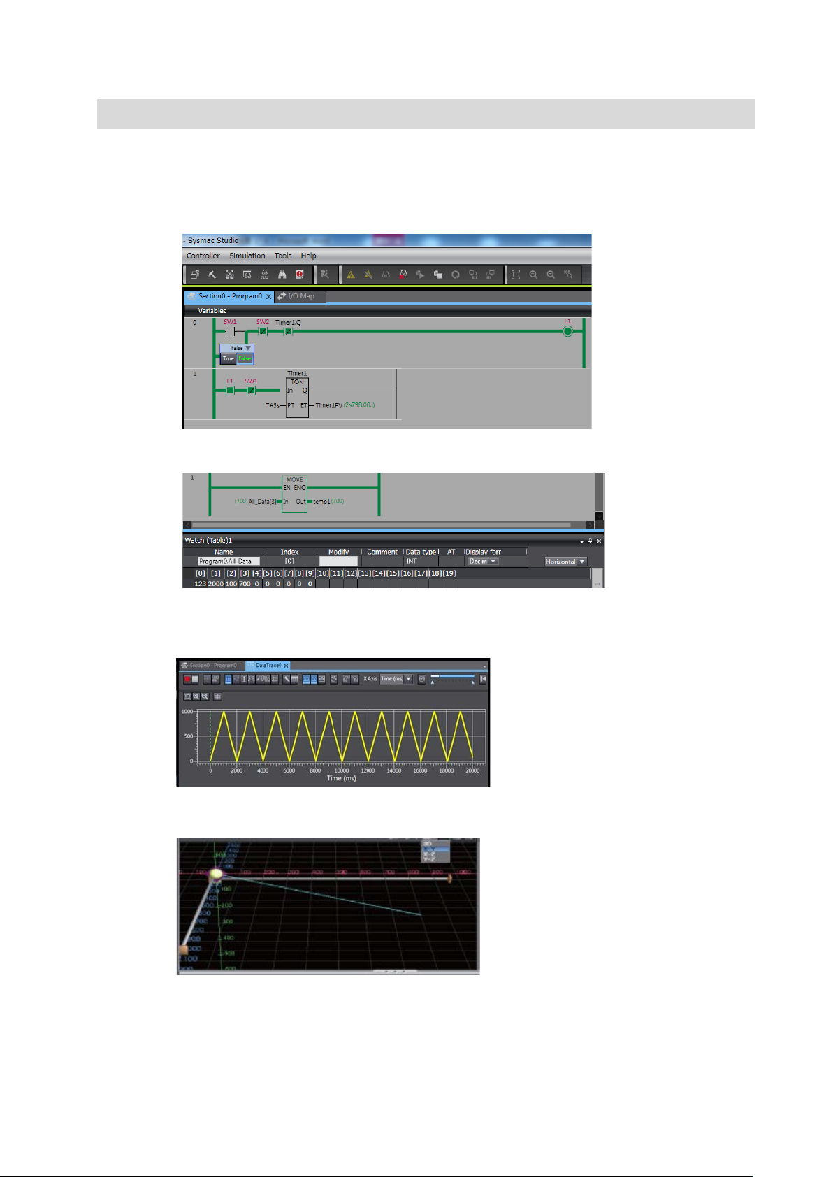
5-4 Data Tracing .................................................................................................... 93
5-4-1 Checking the Operation with Data Traces ......................................... 93
5-5 3D Simulation ................................................................................................... 95
5-5-1 Starting 3D Simulation ....................................................................... 95
6 ST Programming ..................................................................... 97
6-1 Overview of ST Programming ......................................................................... 98
6-1-1 Advantages of ST Language ............................................................. 98
6-1-2 ST Programs Including Constructs .................................................... 98
6-1-3 Structure of ST and Example ............................................................ 99
6-1-4 Operators ........................................................................................... 99
6-2 NX1P Program ming in ST ............................................................................. 100
6-2-1 Writing an ST Program for NX1P .................................................... 100
6-3 ST Programming Exercise ............................................................................. 101
6-3-1 Exercise of Numerical Calculation Programming ............................ 101
6-3-2 Programming Procedures................................................................ 102
6-3-3 Checking the Program ..................................................................... 104
6-3-4 Checking the Operation of the ST Program .................................... 104
13
Page 14

1
1 Programmi ng the NX 1P
This section describes the fund amental elements of progr amming an NX1P
Machine Automation Controller .
1-1 Overview ....................................................................................................... 1-15
1-2 Features of NX1P Progr a mming .................................................................. 1-16
1-2-1 Challenges in Development and Solutions Using the NX1P ......... 1-16
1-2-2 Easy to Add Programs ................................................................... 1-17
1-2-3 Easy Motion Programming ............................................................ 1-18
1-2-4 Structured Text Language for Easy Mathematical Processing ..... 1-19
1-3 Programm ing with Variables ......................................................................... 1-20
1-3-1 Programming the NX1P ................................................................. 1-20
1-3-2 Data Types .................................................................................... 1-23
1-3-3 Benefit of Using Data Types .......................................................... 1-24
1-3-4 International Standard IEC 61131-3 .............................................. 1-25
1-4 Programming Software ................................................................................. 1-26
1-4-1 Programming Software Sysmac Studio ......................................... 1-26
1-4-2 Simulations .................................................................................... 1-27
14
Page 15
1-1 Overview
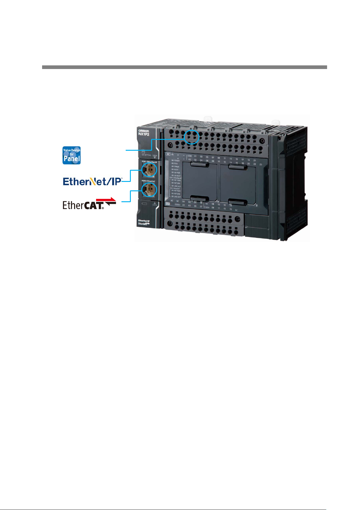
Push-In Plus
The photo below shows a n NX 1P 2 CPU Unit. Push-In Plus terminal blocks are used to
connect a power supply a nd I / O devices.
EtherCAT and EtherNet/IP ports are built in.
terminal
block
Features
1. The built-in EtherCAT port and adv anc ed mot ion c ont rol ma ke mach ine s fast er and more
precise
• Up to four axes of motion control. Electronic cams a nd interpo lation incr ease mach ine
speed and precision
• EtherCAT simplifies the wiring to up to eight servo systems including for single-axis
position control
2. Networks for IoT
• EtherNet/IP enables communications with a host PC and data links bet w een
NJ/NX-series Co nt r ol lers and CJ-series PLCs
3. Push-In Plus terminal blocks
• Push-In Plus connection reduces w iri ng t ime when a control panel is built
The environment for progr am m in g t he NX 1P makes developm ent f as t er and easier.
This Guide describes the feat ur es of NX1P programming and how to program the NX1P
using the Sysmac Studio.
15
Page 16
1-2 Features of NX1P Programming
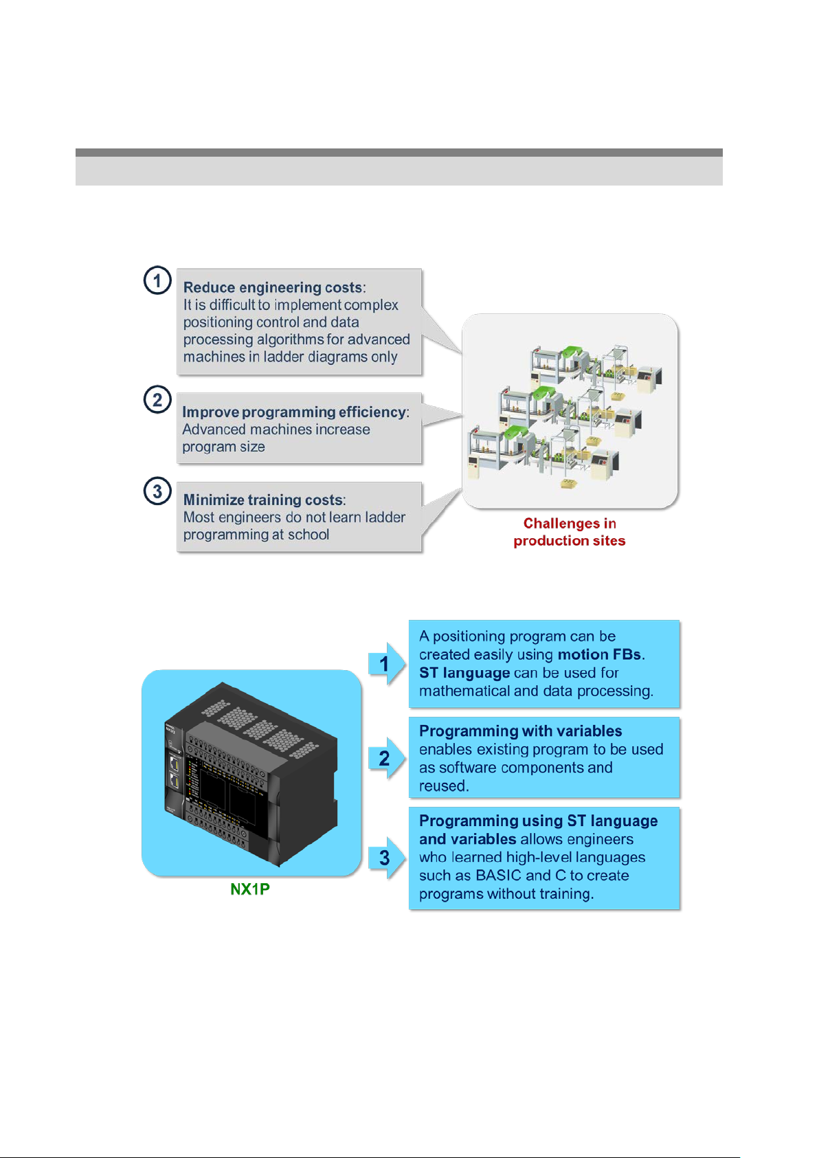
1-2-1 Challenges in Devel opm e nt a nd S olutions Us ing the NX1P
As manufacturers need to improve productivity and qua lity, machines are getting more
advanced and more complex. Engineers are facing challenges such as reducing
engineering costs, improving programming effic ien cy, and minimizing train in g c ost s.
The NX1P can offer soluti ons t o each challenge.
The next section gives more det ailed explanation about pr ogr amming the NX1P.
16
Page 17
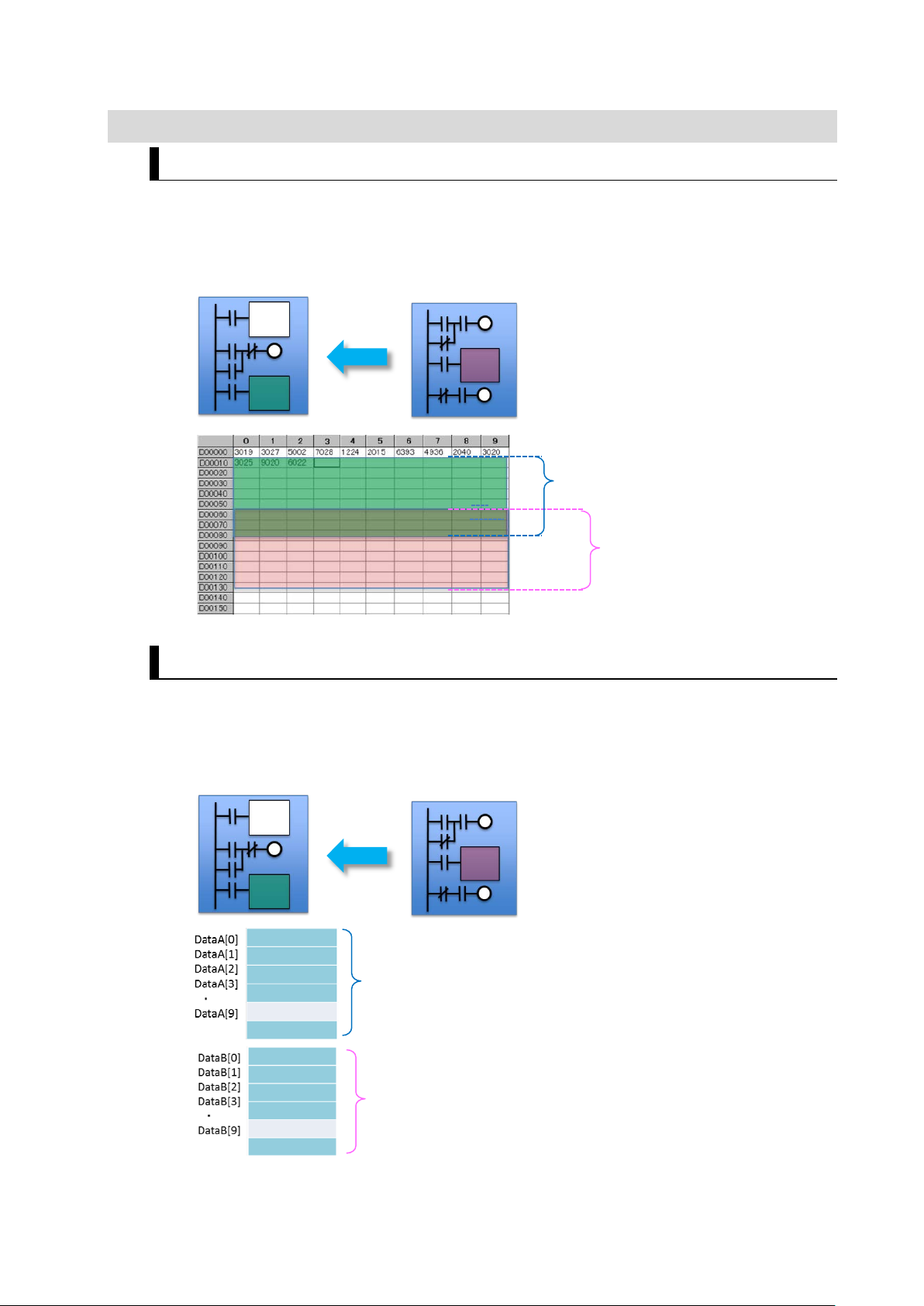
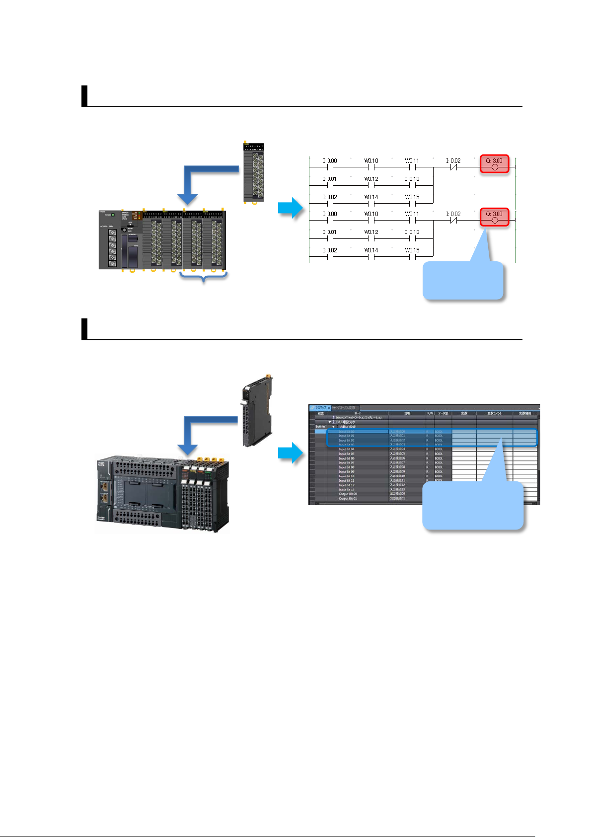
1-2-2 Easy to Add Programs
Memory area used for
Memory area used for
Memory area allocated for
Memory area allocated for
Previously
When adding a program, the user neede d t o check whether the I/O addresses and memory
area used for the additional program had already been used. If they were used,
modifications and debugg ing w ere requ ired. These t asks redu ced d ev elopmen t productiv ity .
Existing program Program to add (reused)
existing program
The same area is used
Programming the NX1P
When a program is reuse d, the NX1P automatically allo cat es memory addresses in t he
memory area for variables. The user does not need to worry about addresses when add ing or
modifying the program. Debugging time can also be reduced.
Existing program Program to add (reused)
variables of existing program
program to add
variables of program to add
17
Page 18
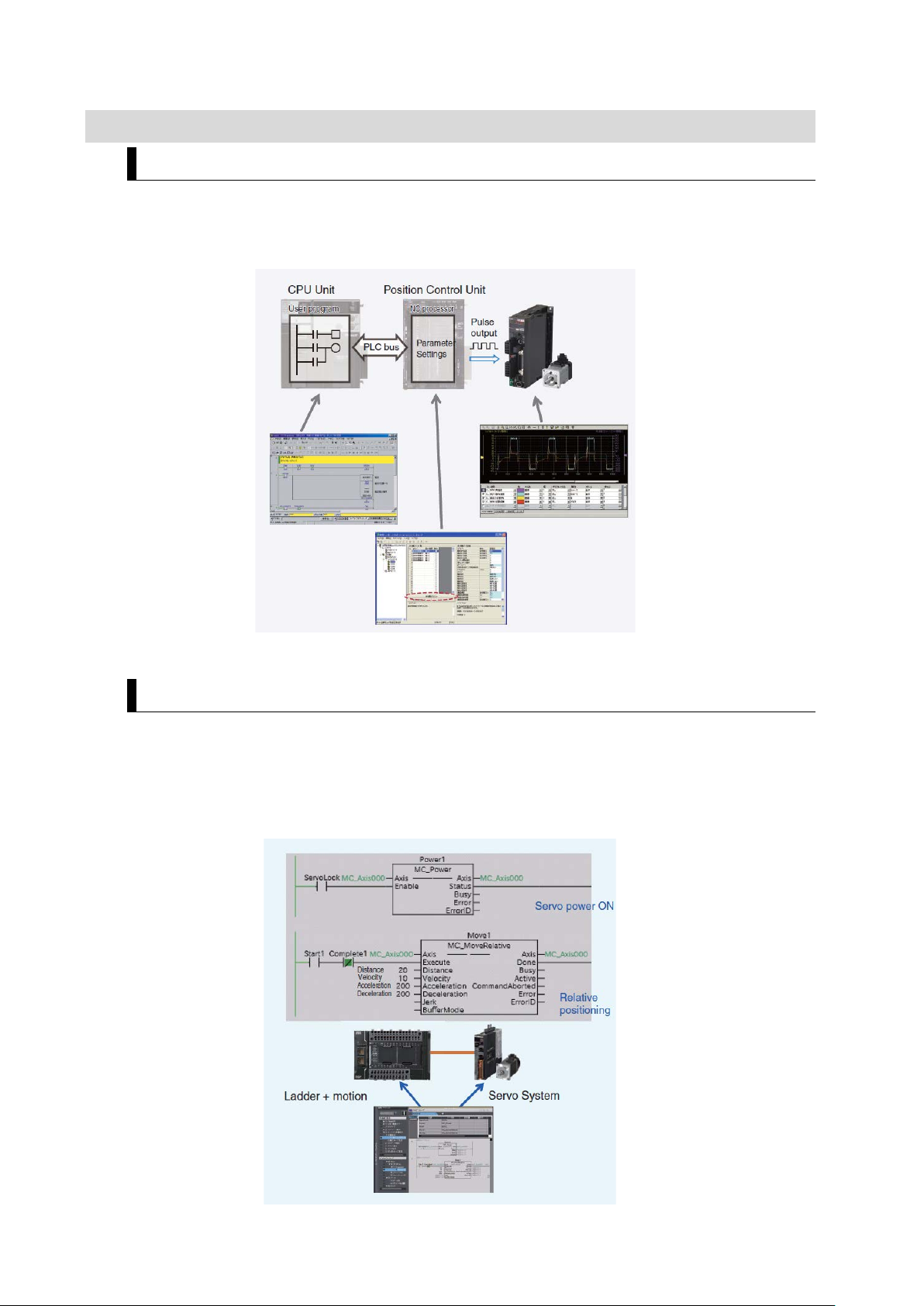
1-2-3 Easy Motion Programming
Previously
The traditional PLC (e.g., CJ2) used three different software applications for Position Control
Unit settings, ladder programming, and Servo Sy s t em sett i ngs . The user had to create a
program while monitorin g and t uning the settings.
Programming the NX1P
Operations such as turning ON the Servo, homing, and positioning can be de scr ibed in one
program by using motion FBs.
Processes are executed from top to bottom, which ma kes t he program easy to read.
The Sysmac Studio integrating ladder programming, motion, and Servo configuration
facilitates positioning control. Simple monitoring and modification!
18
Page 19
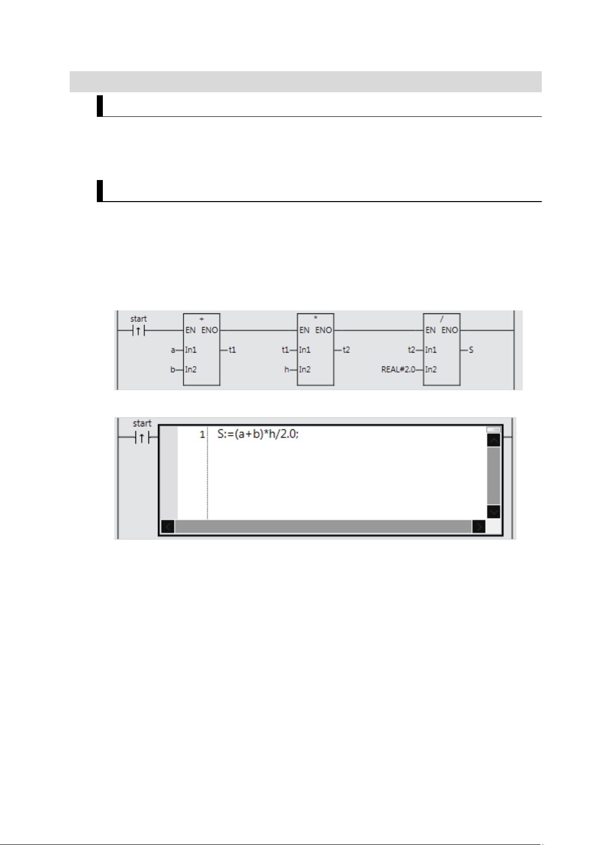
1-2-4 Structured Text Language for Easy Mathematical Processing
Structured Text Language
The structured text (ST) la nguage is a high-level structur ed language, similar to Pascal. I t is
ideal for mathematical processing and nested conditional branching that are difficult to write
in ladder diagrams.
Features of ST Language
You can create easy to read progr ams by using two different program m in g languages,
ladder diagram language f or sequence control and ST language for mathematical
processing.
Example: Calculating the area of a trapezoid
(Top length + bottom lengt h) * height / 2
The ST language simplifie s t his cod e.
You can use ST as an element in a l adder diagram or create a pr ogr am in ST only.
ST is ideal for:
1. Arithmetic operations an d fun c t io n c al culation
+, -, *, /, SIN, COS, TAN, etc.
2. Loop and condition constructs
IF THEN, FOR NEXT, etc.
3. Text string processing
Joining, extracting, searching, and replacing text st rings
The next section gives more det ailed explanation about pr ogr amming with variables.
19
Page 20
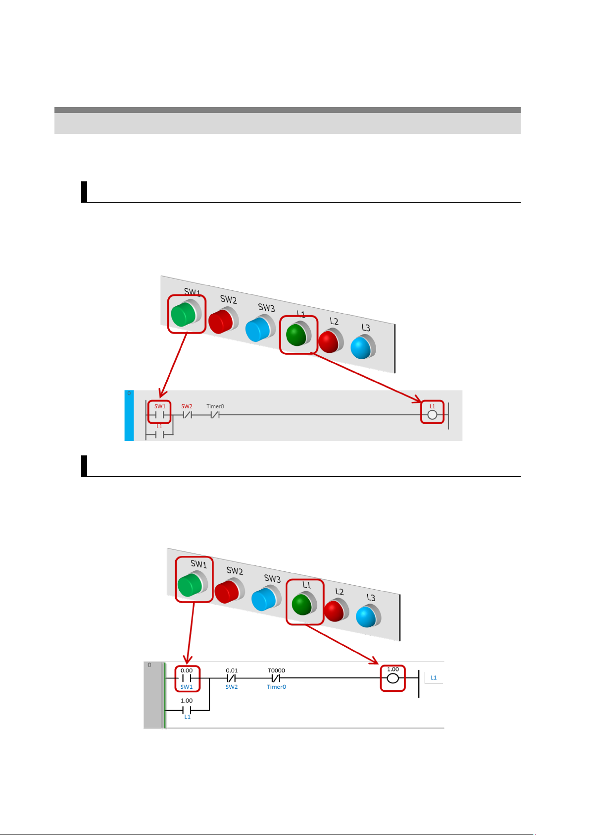
1-3 Programming with Variables
1-3-1 Programming the NX1P
Variables are names defined by the user. They are used for programming t he NX 1P
although addresses are used for the CJ2 and other traditional PLCs.
Programming the NX1P
Programming with variables eliminates the need to remember addresses and makes
programming faster and easier.
Programming with variables means that you can cr eat e pr ogr ams using the names on your
control panel or touchscreen as shown below.
Programming Traditional PLCs
I/O numbers and timer nu mb er s ( 0. 00 and T0000 shown in the figure below) are used to
program traditional PLCs such as CJ2.
For most PLCs, comment s can be added to the numbers in order to easily understand what
the numbers mean. Omro n calls the comment “I/O comment”.
20
Page 21

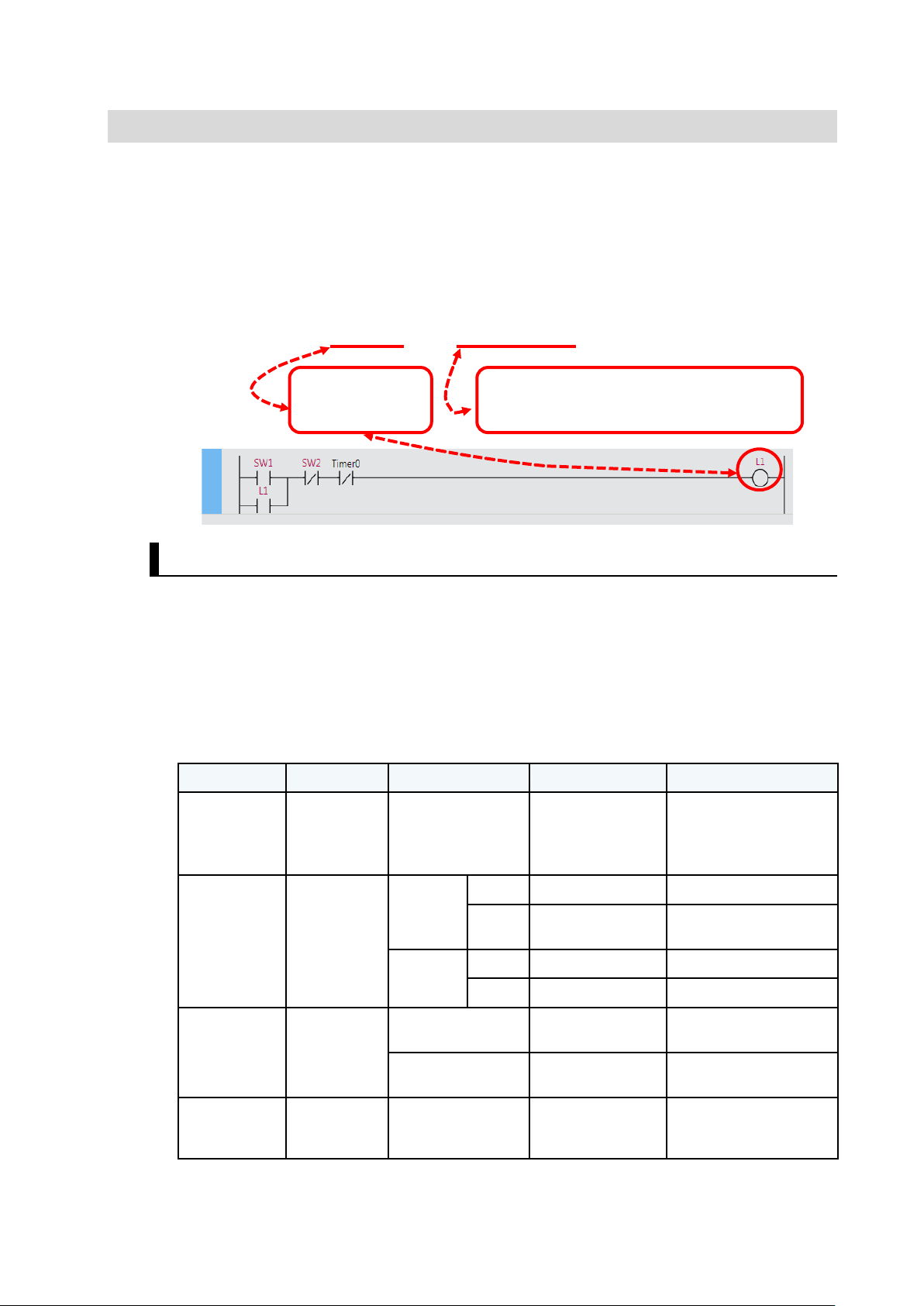
Difference between Programming with Addresses and with Variables
CJ2 program example
NX1P program example
NX1P
I/O Map
This section shows the difference between two prog r am m in g m et hods.
The CJ2 program (created with the CX-Programmer ) and NX 1P program (created with t he
Sysmac Studio) are show n below.
Two programs shown above were written to perform t he sam e operation.
To program the NX1P, ea ch v ariable (e. g., SW1 and L1) must be ass igned in the I/O Map to
the corresponding input / out put t er m inal to which the physical device is connected.
Variables used in the progr am ar e li nked with actual I/O ( input/output terminals of the NX1 P
in this example). You can change I/O assignments by simply changing the terminal number
in the I/O Map. The benefit of programmi ng w it h variables is that there is no need to change
the program itself.
21
Page 22
Addresses are changed
Adding
a Unit
Change all related
Adding
a Unit
Just assign the device
I/O Map for NX1P
Previously
When changing the Unit conf iguration, you had to change addresses in the ladder program
because the addresses assigned to the I/O channels were changed.
addresses in the
ladder program
Programming the NX1P
Even when adding Units, you just assign variables to new I /O ports in the I/O Map without
changing the program.
variables to the I/O
ports of the added
Unit
22
Page 23
1-3-2 Data Types
Classification
Used for
Data type
Range of values
Notation
Boolean
ON/OFF status
BOOL
0 to 1
INT
-32768 to +32767
+30000, -20000
DINT
-2147483648 to
+2147483647
+12345678, -20000000
UINT
0 to 65535
60000
UDINT
0 to 4294967295
20000000
Floating-point
Real number
REAL
Single-precision
floating-point values
0.15625
LREAL
Double-precision
floating-point values
1.0000000000000002
Text string
Text string
HMI
STRING
Text strings (UTF-8)
‘OMRON’
using the name
real number, and text string) of data
For example, you define a variable called L1 (meaning the 1st lamp). It is clear that L1
contains ON/OFF data be caus e L1 is a lamp.
However, if you define a variab le called Data1, Data1 may contain a decimal num ber ,
decimal point number, or text string.
The data type defines the type of data that is expressed by a variable.
A variable is a container for dat a w ith a name and data type.
Variable = (Name) + (Data type)
Examples of Data Types
Programming
Defines the range and type (e.g., integer,
The table below lists the data types used for the NX1P. Th e BO O L dat a t ype is used for
ON/OFF data, the INT data t ype for decimal integers, and the STRING data type for text
strings.
Although both the INT and DIN T dat a t ypes represent decimal integers, they have differe nt
ranges of values.
The WORD data type for bit st r ing s , t he DA TE_AND_TIME data type for date and time, and
other data types can also be used.
・1 or 0
・TRUE or FALSE
Decimal
number
(integer)
number
of inputs and
outputs
Numeric
operation
Signed
Unsigned
displayed on
Approx. 2,000 bytes
‘Failure rate’
23
Page 24
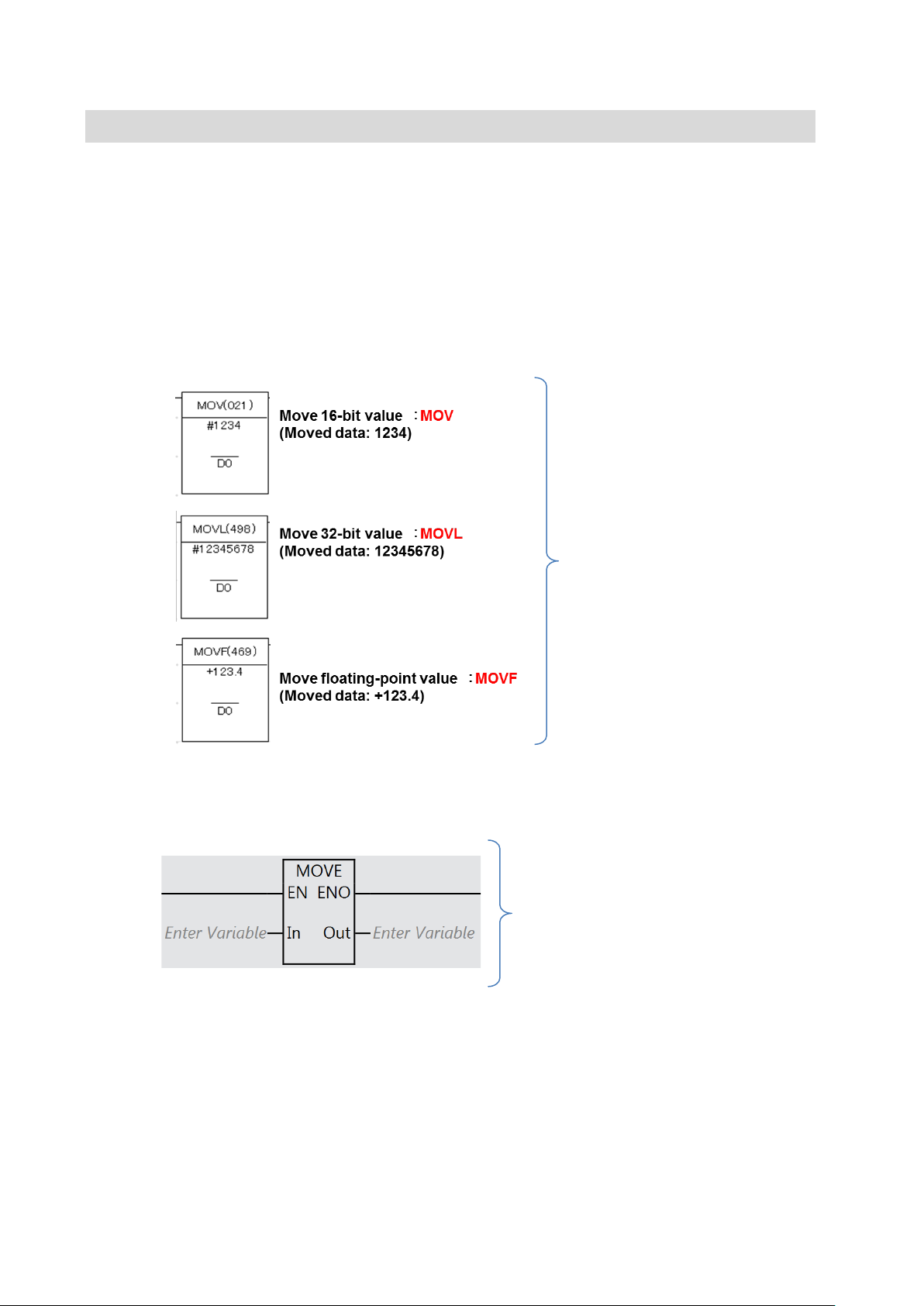
1-3-3 Benefit of Usi ng Data Types
● CJ2 or traditional PLC
● NX1P
MOV, MOVL, M OV F , etc.
Move floating-point value ⇒ REAL
When special instructio ns are used for a traditional PLC such as CJ2, different instr uct ions
must be used for different types of data.
With the NX1P, operands of sp ec i al instructions are specified with variables. As the
variables contain data types, there is no need to use differ ent instructions for differ ent dat a
types.
Even when the data length is cha nged from 16 bits to 32 bits, all you have to do is change
the data type. You don’t need t o change the program or allocate memory.
Different special instructions for
different types or lengths of data.
24
MOVE instruction only.
The concepts of “progra m m ing w ith variables” and “dat a types” based on the inter nat ional
standard IEC 61131-3 are rapidly spreading.
Specify the appropriate data types for
move source In and move destination
Out when the type or length of data is
changed.
Move 16-bit value ⇒ INT
Move 32-bit value ⇒ DINT
Page 25
1-3-4 International Standard IEC 61131-3
IEC 61131-3
IEC 61131-3*1 is an international standard that i s in it ially published in 1993.
• Manufacturer and hardware-independent
• Reusable software components
• Five programming languages for a variet y of purposes and skill levels
*1. IEC (International Electrotechnical Commission)
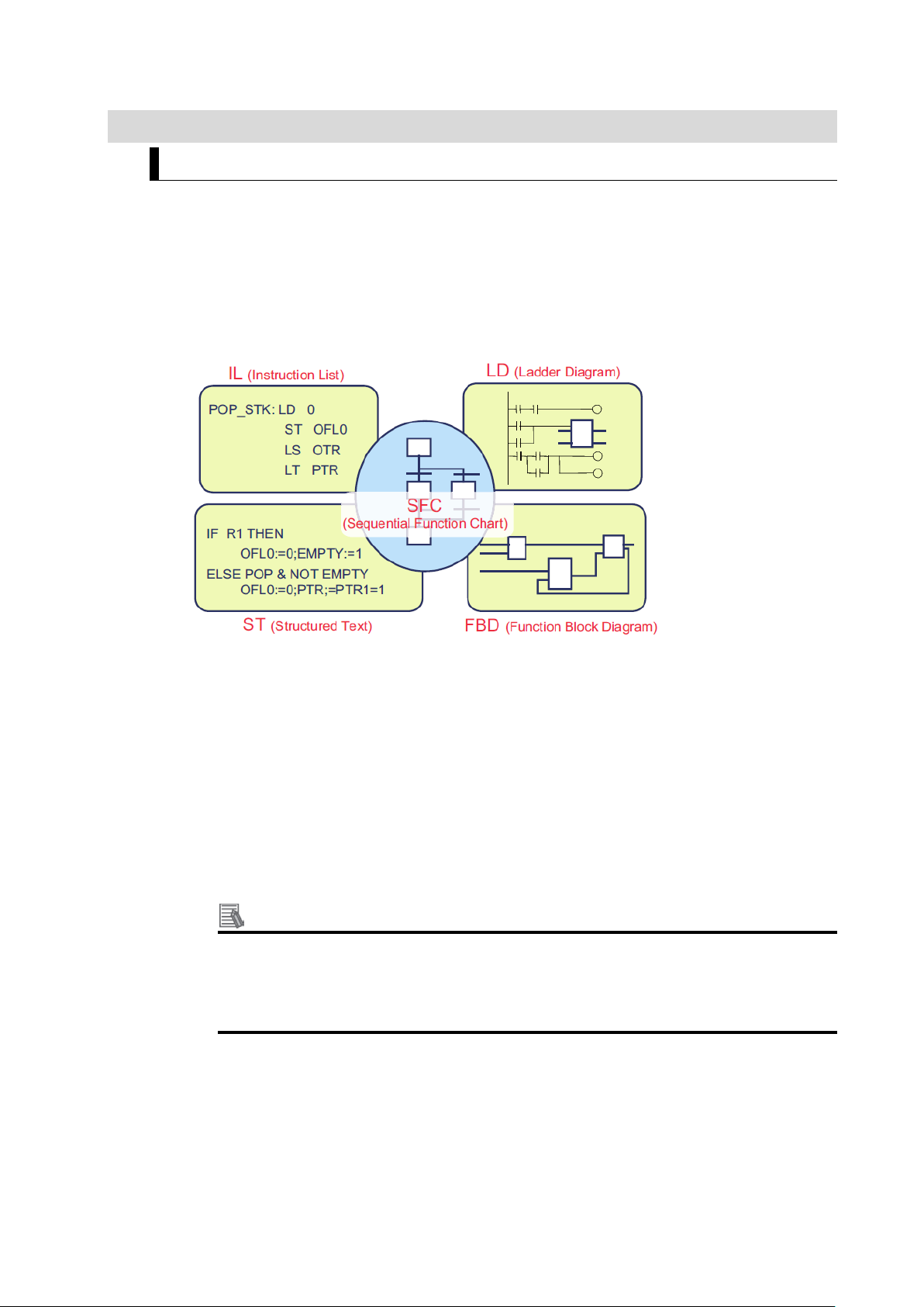
Five programming langu ages according to IEC 61131-3
• IL (Instruction List): A low-level text language similar to assembly
• LD (Ladder Diagram): A graphical language written in a form similar to electrical circuits
• ST (Structured Text): A high-level structur ed language similar to Pasc al
• FBD (Function Block Diagram):
A graphical language to descr ibe the function as a set of ele mentary blocks
• SFC (Sequential Function Chart):
A graphical language used to program processes that c an be split into steps
The NX1P supports LD and ST.
Adoption of the IEC 61131-3 standard
The adoption of the IEC 61131-3 standard is widespr ead from Europe and North
America to Asia.
The NX1P support progra mm ing lan guages b ased on IEC 6 113 1-3. Engineers can be
trained easily thanks to familiar programming languages.
25
Page 26
1-4 Programming Software
1-4-1 Programming Sof tware Sysmac Studio
The Sysmac Studio
The Sysmac Studio provides an integr ated dev elopme nt environ ment to configure, program,
debug, and maintain NJ/N X-series Machine Auto ma t ion Controllers.
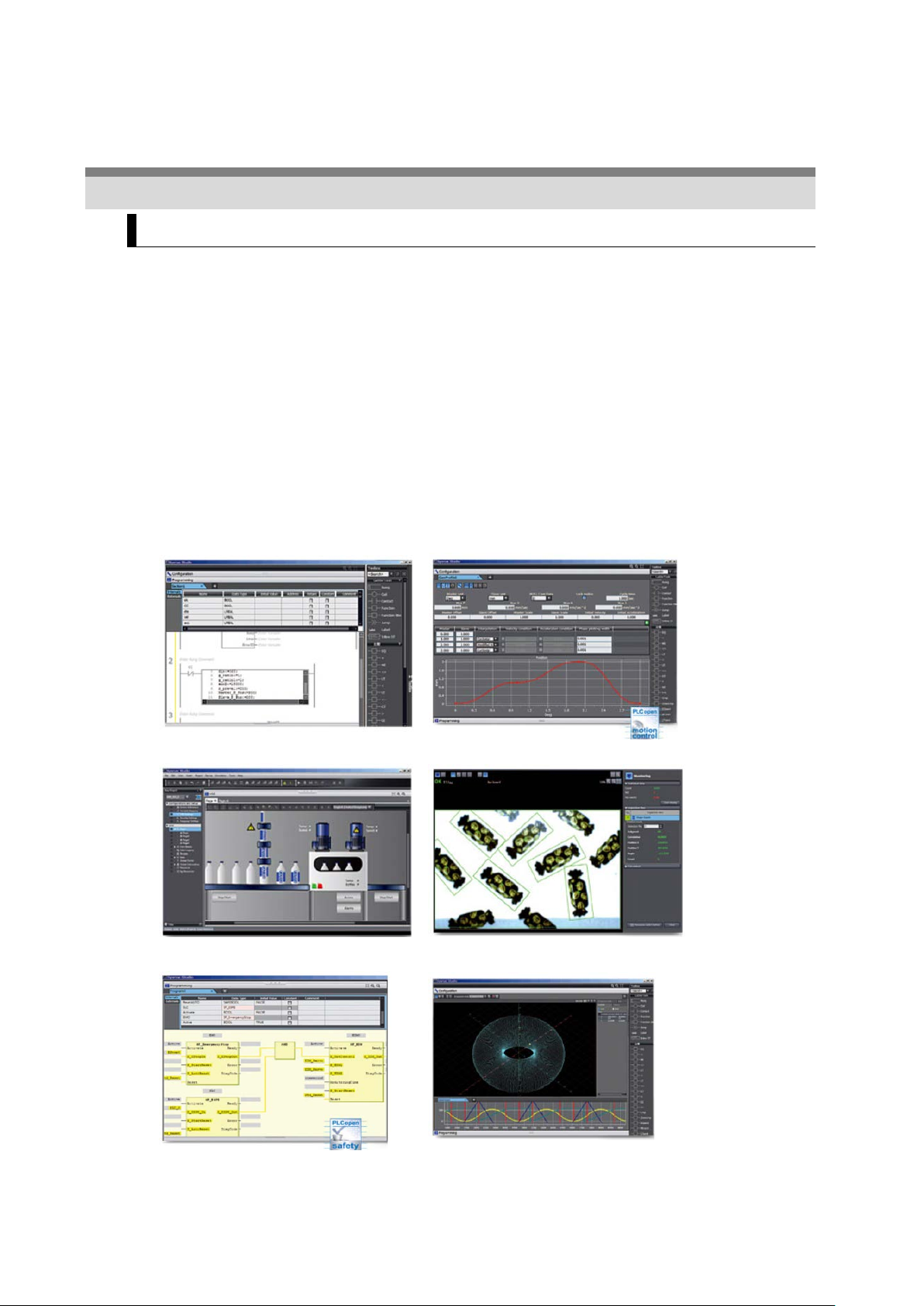
Features
1. One software integrates configuration, progra m m in g and monitoring
2. Programming with variables. Supports the ladder and ST languages and FBs
based on IEC 61131-3
3. PLCopen function blocks f or easy programming of complex motion profiles, and
Cam Editor for quick implementation of cam motion profiles
4. Integrated simulation and debugging
Motion trajectories in 3D can be pr e-tested, and simulati on of programs can be
performed. This reduces set-up and tuning time.
*1. ST language (Structured Text language), FB (Function Block)
Programming Motion control
HMI Vision sensors
Safety Simulation
*1
26
Page 27
1-4-2 Simulations
The Sysmac Studio provides a variety of simulations.
The Simulator in the Sysm ac Studio all ows you to t est progra ms without connect ing physic al
devices.
1. Check the operations of a pr ogr am
2. Monitor variables in the Watch Tab Page without conn ecting devices
3. Check a motion program by viewing the changes of positio ns and velocities sampled
by data tracing
4. Check motion trajector i es by performing 3D motion monitoring, without con nect ing
physical devices
27
Page 28

2
2 Before You B egin
This section describes the pr ocess of hardware mounting a nd w iring and the
installation of the Sysmac St udio.
2-1 System Conf igurat ion and Devices .............................................................. 2-29
2-1-1 Overview ........................................................................................ 2-29
2-1-2 Wiring ............................................................................................. 2-30
2-2 Installing the Sysmac Studio ........................................................................ 2-32
2-2-1 Installing the Sysmac Studio ......................................................... 2-32
2-2-2 Requirements for Installation ......................................................... 2-32
28
Page 29

2-1 System Configuration and Devices
Version 1.17 or higher
(1 license)
Pushbutton Switch
Indicator
Power Supply
A22NL etc.
M22N etc.
S8VK-S06024 etc.
2-1-1 Overview
Connect a Power Supply , Pushbut t on Switches, and Indicator s t o t he NX1P and create a
ladder program in Section 3 Ladder Programming.
Automation Software
Sysmac Studio
Standard Edition
SYSMAC-SE200D
(DVD only)
SYSMAC-SE201L
The physical devices such as NX1P, Pushbutton Switches, and Indicators w i ll hel p you
understand programming conce pts.
Even if there is no physica l device, you can check operatio n using the Simulator in the
Sysmac Studio.
Section 4, 5, and 6 explain about simulations.
Machine Automation
Controller
NX1P
NX1P2-□□□□ -
Ethernet cable
(100Base-TX/10Base-T)
29
Page 30
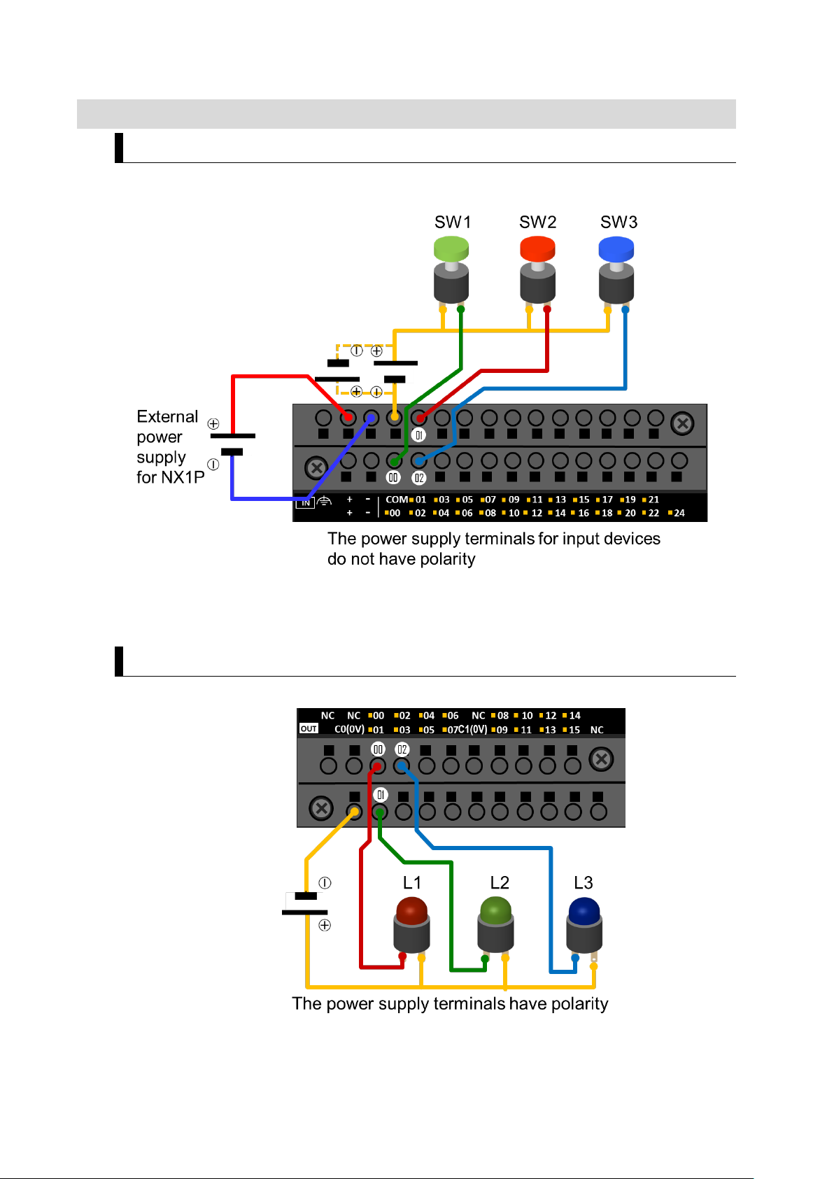
2-1-2 Wiring
Wiring Pushbutton Switches
Wire Pushbutton Switches to the NX1P as shown below.
Wiring Indicators
30
Page 31

Push-In Plus Terminal Blocks
Held securely with
Flat-blade
Remove the
A push-in terminal block allows you to connect wires (e.g. ferrule) by just pushing t hem in.
Reducing wiring work can gr eatly reduce the time required to build control panels.
Push-In Plus Terminal Blocks were independently developed by Omron for ea s ier w ire
insertion and firmer wire holding ability than standard push-in terminal blocks.
You can connect and re m ove a wire (solid or ferrule) t o/ from a Push-In Plus Terminal Blo ck
by following the procedure below. (Refer to the manual for connection and removal of a
stranded wire)
■ Connecting a wire
Just push the wire into the ter minal b lock until stopping. When connecting a stranded wire,
use a ferrule, or insert the wire after loosenin g t he clamp spring with a tool and then remove
the tool.
■ Removing a wire
Press a flat-blade screwdriver diag onally into the release hole to l oosen the clamp spring
and then remove the wire. Re mov e t he f lat-blade screwdriver.
screwdriver
clam p sprin g
screwdriver
31
Page 32

2-2 Installing the Sysmac Studio
OS
CPU
RAM
Display
colors
equivalent
colors
2-2-1 Installing the Sysmac Studio
The Sysmac Studio is the support software to config ur e, pr ogr am, debug, and simulate
NJ/NX-series Co nt r ol lers .
Use the following procedure to install the Sysmac Studio on your computer.
1. Set the Sysmac Studio installation disk into the DVD-ROM drive.
The setup program is start ed auto mat ically and th e Se lect Set up La nguage Dialo g Box is
displayed.
2. Select the language to use, and then click the OK Button.
The Sysmac Studio Setup Wizard is started.
3. Follow the wizard to install the Sysma c St udio.
4. Restart your computer after the Sy s ma c St udio has been success ful ly inst alled.
2-2-2 Requirements for Installation
The system requirements for t he Sysmac Studio are giv en in the f ollowing table.
Windows 7
32-bit or 64-bit edition
Windows 8
32-bit or 64-bit edition
Windows 8.1
32-bit or 64-bit edition
Windows 10
32-bit or 64-bit edition
Precautions for Correct Use
When the CX-One version 4 or lower has been installed, uninstall it before installing
the Sysmac Studio.
Minimum IBM AT or compatible with
Recommended IBM AT or compatible with
®
Intel
Celeron® processor 540
(1.8 GHz)
®
Intel
Core™ i5 M520
processor (2.4 G Hz) or the
2 GB XGA
1,024 x 768
16 million
4 GB
min.
WXGA
1,280 × 800
16 million
32
Page 33

3
3 Ladder Programming
3-6-1 Self-holding Rung .......................................................................... 3-53
This section describes how to writ e ladder pr ograms using the Sys mac Studio.
3-1 Programm ing with the Sysmac Stud io ......................................................... 3-35
3-1-1 Programming Procedure................................................................ 3-35
3-1-2 Creating a Project .......................................................................... 3-35
3-2 Parts of the Sysmac Studio Window ............................................................ 3-37
3-2-1 Screen for Configurations and Setup ............................................ 3-37
3-2-2 Screen for Programming................................................................ 3-37
3-3 Assignin g Variables to Terminals ................................................................. 3-38
3-3-1 Variable Names for Terminal Numbers ......................................... 3-38
3-3-2 I/O Map Setting .............................................................................. 3-39
3-3-3 Checking Wiring ............................................................................. 3-41
3-4 Ladder Programming .................................................................................... 3-42
3-4-1 Inserting Circuit Parts .................................................................... 3-42
3-4-2 Keyboard Mapping ......................................................................... 3-42
3-4-3 Rules .............................................................................................. 3-43
3-5 Example of a Basic Ladder Program ............................................................ 3-44
3-5-1 Practice of Programming a Ladder Diagram ................................. 3-44
3-5-2 Writing the Algorithm ..................................................................... 3-45
3-5-3 Program Check .............................................................................. 3-47
3-5-4 Saving the Program ....................................................................... 3-48
3-5-5 Checking Operation on the NX1P ................................................. 3-49
3-5-6 Checking Operation on the Simulator ............................................ 3-50
3-5-7 Example of a Program Error (Offline) ............................................ 3-52
3-5-8 Example of an Error Occurred During Operation .......................... 3-52
3-6 Example of a Ladder Program Using a Ti m er I nst r uc t ion ............................ 3-53
33
Page 34

3-6-2
3-6-3 Exercise: Energy Saving Es c alator ............................................... 3-58
3-6-4 Checking the Operation of the Program ........................................ 3-59
3-6-5 Checking the Operation of the Program (Watch Tab Page) .......... 3-60
3-7 Example of a Ladder Program Using Date and Time .................................. 3-62
3-7-1 Programming the NX1P Using Date and Time .............................. 3-62
3-7-2 Exercise: Continuous Operating Time of Escalator ....................... 3-62
3-8 Fundame ntals of Progra mming to Reduc e Develo pme nt Time ................... 3-66
3-8-1 POUs (Program Organization Units) ............................................. 3-66
3-8-2 Programs and Execution Priorities (Tasks) ................................... 3-66
3-8-3 Functions (FUNs) and Function Blocks (FBs) ............................... 3-68
3-8-4 Sections ......................................................................................... 3-69
3-8-5 Types of Variables ......................................................................... 3-70
On-Delay Timer (TON) Instruction ................................................. 3-54
34
Page 35

3-1 Programming with the Sysmac
Connecting NX1P to debug program using physical devices
Assigning variables to connected I/O devices in I/O Map
Programming
Creating a project
Studio
3-1-1 Programming Procedure
This section describes how to create a simple ladder pr ogr am using pushbutton s w itc hes and
lamps.
The overall programming procedure is given below.
3-1-2 Creating a Proje c t
1. Start the Sysmac Studio.
2. Enter the project name.
Select NX1P2, 9024DT/1140DT for the device parameter and 1.13 (version indicated on th e
NX1P) for the version parameter, and t hen click the Create Button.
35
Page 36

Right-click
The following window is displayed.
Additional Information
You can change the model, version, and other propert ies after cr eating a project file.
36
Page 37

3-2 Parts of the Sysmac Studio Window
and Setup
Toolbox
Programming
Edit Pane
Pane
to set up
create programs
assistant tools
3-2-1 Screen for Configurations and Setup
Configurations
Multiview
Explorer
3-2-2 Screen for Programming
1. Select an item
2. Make settings or
Simulation
3. Use as setup
37
Page 38

3-3 Assigning Variables to Terminals
3-3-1 Variable Names for Ter m inal Numbers
Although Pushbutton Switches and Indicators are physically connected to t he input and output
terminals of the NX1P, they cannot be used for programm ing now.
In order to create a program usin g t he c onnected devices (I/ O ) , you need t o assign variable
names for the numbers of termina ls to which devices are conne ct ed.
Any name can be assigne d. Names r elated to t he dev ice type or processin g are reco mmended.
For example, you can use “SW1” for a Pushbutton Switch co nnected to the input t erminal 00 of
the NX1P because “SW1” is its na me on the n amep lat e in the contro l pa nel. This makes it easy
to identify the device.
38
Page 39

3-3-2 I/O Map Setting
Variable
name
Variable
name
Input bit 01
Input bit 02
Set variables for terminals.
I/O map setting means that variables used for a progra m are assigned to terminals (called “I/O
ports” in the Sysmac Stud i o) of t he NX 1P to which devices (I/ O ) ar e connected.
1. Double-click I/O Map under Configurations and Set up on the Multiview Exp lorer . The I/O
Map is displayed.
As the NX1P is selected f or the dev ice, al l input/ out put t ermina ls (I/ O port s: I nput Bit 00 et c.)
of the NX1P are displayed in the I/O Map.
2. Double-click an I/O port to enter a variable name.
Set variable names for input / out put terminals as shown below.
Variable names for input t er m inals Variable names for output termina ls
Terminal No. R/W
Input bit 00
*1. SW means a switch (Pushbutton Switch).
*2. L means a lamp (Indicator).
R SW1*1 BOOL Output bit 00 R L1*2 BOOL
R SW2 BOOL Output bit 01 R L2 BOOL
R SW3 BOOL Output bit 02 R L3 BOOL
Data type Terminal No. R/W
Data type
3. Enter “SW1” in the Variable Column of Input Bit 00.
39
Page 40

4. In the same way, set SW2 and SW3 for Input Bit 01 and 02 and L1 to L3 for Output Bit 00 t o
02.
The variable names have been linked with the terminal numbers.
40
Page 41

3-3-3 Checking Wiring
Go online
Transfer to Controller
1. Connect the NX1P to the computer (Sysmac Stud io) via an Ethernet cable.
2.
Go online, and then transfer t he I/O map settings to the NX1P.
3. Change the operating mode to PROGR AM mode to prevent the progra m fro m being
executed while checking I/O wiring.
Change to PROGRAM mode
4. Press the Pushbutton Switches to c heck whether the values o f the input bits change in the
I/O Map.
5.
Select the I/O port. Right-click and select Set or Reset from the menu to chec k whet her the
Indicator turns ON or OFF.
41
Page 42

Operation
Shortcut keys
Reference (Shortcut key in CX-Programmer)
C
Entering an N.C. input
/
Same key
W
Entering an OR with an N. C . input
X
Same key * Different cursor position
O
Entering a NOT output
Q
Same key
F
Calling a functi on
I
Different key * First letter of instruction
R
Inserting a rung above the cursor
Shift + R
3-4 Ladder Programming
3-4-1 Inserting Circ uit Parts
Inserting a Program Input or Output in an AND Structure
Shortcut key: Select a connecting line a nd pr es s t he shortcut key
Example: N.O. Input - C Key, output - O Key
Toolbox: Drag a c ircuit part from the Toolbox
Right-click: Right-cl ick a conn ect ing line a nd s elect Ins ert Inp ut or Insert Output from the
Menu.
Inserting a Program Input in an OR Structure
Shortcut key: Select an input and press t he W Key. (The N.O. input is ins er t ed in an OR
structure)
Drag and drop: Drag the c onnecting line and select a circuit part from the pop-up menu
Inserting a Rung
Shortcut key: Select the start of a rung and pres s t he R Key.
Right-click: Right-click a rung and select Insert rung above or I nse r t r ung below.
3-4-2 Keyboard Mapping
The following table lists th e shor tcut keys that you can use when creating ladder programs.
Entering an N.O. input
Entering an OR with an N. O . input
Entering an output
Calling a functi on block
Inserting a rung below the cursor
* Select Keyboard Mapping R efer ence from the Help Menu to display the Keyboard Mapping Reference.
Same key * C or L in CX-Programmer
Same key * Different cursor position
Same key
Same key * F for both FUN and FB
Same key
42
Page 43

3-4-3 Rules
You Can
With the NX1P, you can progr am a ladder diagra m that cannot be progr ammed with the CJ2 or
other traditional PLC.
You can insert an output without inserting an input. (Always ON Flag is not required)
Functions and function blo c ks can also be inserted wit hout inserting an input.
You can connect outputs, fun c t io ns , and function blocks in series .
You Cannot
You cannot set a rung without any circuit parts.
You cannot set a rung with only one input.
You cannot connect any item other than output after an out put.
43
Page 44

FULL
AVAILABLE
3-5 Example of a Basic Ladder Program
3-5-1 Practice of Progr amming a Ladder Diagram
[Exercise] Coin Operated Parking Space
Three cars can be parked in t he parking space. Crea t e a pr ogr am to turn ON the FULL lamp
(L3 (red lamp)) if the parking lot s are ful l and turn ON the AVAILABLE la mp (L 1 (green la mp)) if
one or more parking lots are available.
SW1, SW2, and SW3 are used as sens or s to detect presence of cars.
Completed program
44
Page 45

3-5-2 Writing the Algorithm
1. Click POUs under Programming in the Multiview Explorer.
Programs, Functions, and Function Blocks are d isplayed under POUs.
2. Double-click Section0 under Programs - Program0.
The Ladder Editor is displayed.
3. Write a ladder program on the Ladder Editor.
Additional Information
When a new ladder program is create d, Sectio n0 wi ll be mar ked with a red ! mark ( ).
This mark means that the program contains an error. I t w ill disappear when the program
is written correctly.
45
Page 46

S と入力し、変数リストから SW1 を
選択して、[Enter]キーを押す。
コメントが必要なければ、
[Enter]
Right-click
Enter “s”. Select SW1 from
Enter
Just press the Enter Key
comments
(1) Insert a program input in an AND structure
Insert an input and enter the variable name.
1. Press the C Key or right-click a connecting line and select Insert I nput from the
Menu.
the variable list and press the
Key
if you do not enter any
In the same way insert circuit parts as shown below.
2. To insert an output, press the O Key or r ight-click a connecting line and select Insert
Output from the Men u.
(2) Insert a rung below.
1. Select the start of a rung and press the R Key, or right-clic k a rung and select Insert
rung below.
(3) Insert a program input in an OR struct ur e
1. Insert an N.C. input and an output.
Insert an N.C. input by pre s sin g the / Key and then insert an output.
46
Page 47

2. Inset an N.C. input in an OR structure. Select SW1 and press the X Key, or dr ag t he
Drag the connecting line
from the start point
to
the end point
connecting line from the start point to the end point and sel ec t N.C. Input from the
menu.
3. Insert another N.C. Input in the same way.
The program is completed.
3-5-3 Program Check
1. Select Check All Progra m s from the Project Menu.
Warnings and errors
are displayed
47
Page 48

Save
Export
Start page.
The project is Saved as a file.
2. Modify the program if an error is found.
The results of the progra m ch eck are displayed in the Build Ta b Page.
Modify the program if an error is fou nd.
3-5-4 Saving the Program
1. Save and export the project file before taking the next step.
Select Save from the File Menu.
2. Select Export from the File Menu. Enter a file name and export the file to the desktop.
< Useful function >
Double-click the line of the err or t o
jump to the location of the er ror
Additional Information Difference between Save and Export
The project is saved in the defa ult
folder. The user does not need t o
know where the project is saved.
To open the
saved project,
click Open
Project on the
To open the saved
project,
double-click the
file icon or Click
Import on the
Start page.
48
Page 49

3-5-5 Checking Opera tion on the NX 1 P
Connect the NX1P and the Sysmac Studio and download the project (all data includin g t he
program) from the Sysma c Studio to the NX1P to check operat i on.
1. Connect the NX1P to the computer (Sy smac Studio) via an Ethernet cable.
2. Go online.
Start the Sysmac Studio and go online with the NX1P.
3. Download the project.
Click the Transfer to Controller Button.
Transfer to Controller
49
Page 50

4. Change the operating mode to RUN mode.
Check the Controller Stat us Pane. If the mode is PROGRAM mode, change the oper at ing
mode to RUN mode.
Change to RUN mode
5. Check operation.
Turn ON and OFF the SW1, S W2, and SW3 to check whether the AVAIL ABLE lamp (L1)
and FULL lamp (L3) turn ON and OFF.
3-5-6 Checking Opera tion on the Simulator
You can check operation usin g t he Simulator in the Sysmac Studio, without connecting the
NX1P (offline debugging).
1. Select Run from the Simulation Menu to start t he Si mu lat or .
2. The Simulator is started and connected after displaying some messages.
50
Page 51

3. Double-click the input. You can change the value between True ( O N) and False (O FF) to
debug the program, instea d of pressing the physical swit ch.
4. Select Stop from the Simulation Menu to stop the Simulator.
51
Page 52

Marked with a red line or red ! mark
Displays a description
of the error
Button to display the details
Displays status of NX1P
3-5-7 Example of a Program Err or ( O ffline)
Delete the variable name “SW1” of input SW1 offline. Select Check All Programs from the
Project Menu. Errors are disp lay ed in the Build Tab Page.
3-5-8 Example of an Error Oc c urred During Operation
Click the Troubleshooting Button (!) in the toolbar when an error occurs. The example below
shows a verification error that occurs when the NX1 W-CI F01 Serial Communi cat ions Option
Board is not connected physically but is connected on t he Sysmac Studio.
* Double-click Option Board Set tings under Configurations and Setup - Controller Setup to configure the
Option Board settings.
Press the Display Switch
52
Page 53

3-6 Example of a Ladder Program Using
a Timer Instruction
3-6-1 Self-holding Rung
Create a self-holding rung to turn ON L1 when SW1 is pressed and stay lit until SW2 is
pressed.
1. Create the program offline.
2. Delete the program created in 3-5 Example of a Basi c Ladder Program.
Right-click the rung numbers to delete while holding down the Ctrl Key. Press the Delete
Key.
Self-holding rung
Although the ladder progr am is delet ed, t he I/O Map settings are not deleted and r emain t he
same as those configured in 3-3-2 I/O Map Setting.
3. Create the following rungs.
4. Click the SW1 input, and then press the W Key to in s er t L1 in an OR structure.
53
Page 54

the Instructions Reference
Point
5. Click the connecting line to insert an N.C. I nput . Pr ess the / Key and enter “SW2”.
6.
The self-holding rung is cr eat ed.
3-6-2 On-Delay Timer (TON) Ins tr uc t ion
Create a rung to turn ON L2 in five sec onds after SW1 is pressed.
Rung to add
(1) Refer to the help for details of the TON instruction
• Select Instruction Reference - Timer - TON from the Help Menu.
Select an instruction and
press the F1 Key to display
54
Page 55

Additional Information
Data
Data
Durations
TIME
64
8 bytes
T#-9223372036854.775808ms
T#12d3h3s
TIME#25h_3m
Difference between the TON instruction for the NX 1P and the TIM instruction for the
traditional PLC
The TON instruction chan ges t i mer output Q to TRUE when t he set t ime PT elapses after
timer input In changes to TRUE.
The timer is reset when In changes t o FALSE. Elapsed time ET changes to 0 and Q
changes to FALSE.
(2) Input the set time
Specify a TIME data variable for the input paramete r PT when inputting the se t t ime.
For example, input “T#10.12s” to set to 10.12 secon ds.
Classification
type
size
bits
Alignment Range of values Notation
(T#-106751d_23h_47m_16s_
854.775808ms) to
T#+9223372036854.775807ms
(T#+106751d_23h_47m_16s_
854.775807ms)
T#3s56ms
TIME#6d_10m
TIME#16d_5h_3m_4s
T#12d3.5h
T#10.12s
T#61m5s (Equivalent to T#1h1m5s)
55
Page 56

Adding a rung using the On-Delay Timer instruction
1. Insert a rung below.
Right-click the existing rung and select Insert r ung below, or select t he st ar t of a rung
and press the R Key.
2. A rung is inserted below.
3. Insert the N.O. input L1 as shown below.
4. Search for the TON instruction in the Toolbox on the right of the window or select TON in
the Timer in the Toolbox.
5. Add the TON instruction by dragging it from the Toolbox.
* You can also insert the TON instr uc t i on by right-clicking the d esired location, selecting
Insert Function Block from the menu, and entering “TON”.
56
Page 57

6. The TON instruction is inserted.
7. Enter the instance name of the TON instruction.
Click Enter Function Block and enter “Timer1”.
8. Set the parameters.
PT: T#5s
ET: Timer1PV
9. Insert an output that changes to TRUE when Timer1 times out.
Enter “L2” for the variable name.
57
Page 58

3-6-3 Exercise: Energy Saving Escalator
This section explains the operat i on of the TON instruction.
This escalator does not move until someone approa ches it . When a person passes in front of
the sensor (SW1), the mot or ( L1) starts. In or der to save energy, the motor sto ps in five
seconds after the last person pa ss es.
Tips
(1) Modify the created program.
(2) Insert an N.C. Input for timer out put in the r ung to stop the motor. Ther e ar e two N.C.
input methods
① Specify timer output as a work bit (e.g., Timer1UP).
② Use Timer1.Q that represents t he out put status of the timer instruct io n.
(3) Modify so as to reset the timer whe n a per son passes.
Add an N.C. Input (Timer1UP) in the first rung to stop L1 (the motor of the escalator in this
example) when Timer1UP changes to TRUE. Add a nother N.C. Input (SW1) to reset the
present value of the TON ins t r uct ion. The program is completed.
■ Example (Output Timer1UP for when Timer1 times out)
58
Page 59

■ Example (Using Timer1.Q)
Present value of Timer1
L1 lamp
Go
online
Transfer to Controller
Enter “Timer1” and “.” (dot). A list of possible candidates is
displayed.
The list shows that Timer1 has four data: In (input signal), PT
(set time), Q (timer completion flag), and ET (elapsed time).
3-6-4 Checking the Opera t ion of the Program
Check the operation of the pr ogr am.
1. Connect the NX1P to the computer (Sy smac Studio) via an Ethernet cable.
2. Go online, and then transfer the program to the NX1P.
3.
Change input SW1 (passing person) to TRU E. O utput L1 (lamp 1) chang es t o TR U E and
variable Timer1PV (present value of Timer1) is incremented as time elapses.
4. Change input SW1 to FALSE, and check that variable Timer1PV is reset.
5. Change input SW2 (stop button of the escalator) to TRU E, and check that output L1
changes to FALSE and var iab le Timer1PV is reset.
6. Change input SW1 to TRUE. Check that output L1 automatically changes to FALSE and
variable Timer1PV is reset in five seconds after nothing is done.
59
Page 60

● Checking the operation using the Simulator
1. Select Run from the Simulation Menu to start t he Si mu lat or .
2. Double-click the input. You can change the value between True ( O N) and False (OFF) to
debug the programs, inste ad of pressing the physical switc h.
3-6-5 Checking the Opera t ion of the Program (Watch Tab Page)
You can also check the operation of the program in the Watch Tab Page.
Monitoring can be performed online on the NX1P or of fl ine with the Simulator in the same way.
1.
Select Watch Tab Page from the View Menu. The Watch Tab Page is display ed at the
bottom of the window.
2. Click the Watch Tab Page 1 Tab.
60
Page 61

3. Click the Variables Bar at the top of the window. The variabl e t abl e appears. Select the
Drag
Drag
variable to monitor from the variables (external v ar iables and internal variab les) used in the
program and drag it to the Watch Tab Page.
Register Timer1 by dragging it to the Watch Tab Page.
Click the ▼ mark, and check that data (ti mer st ar t flag (In), timer set value (PT), timer
present value (ET), and t imer completion flag (Q)) contained in Timer1 can be monitored.
4. Select the variable to monitor in the Ladder Editor and drag it to the Watch Ta b Page.
Register SW1 by dragging it t o t he Watch Tab Page.
5. Execute the program. You can monitor t he values.
Go offline before taking th e next s t ep.
6.
Save and export the projec t file.
• Select Save from the File Menu.
• Select Export from the File Menu to export the file to the desktop.
61
Page 62

3-7 Example of a Ladder Program Using
Date and Time
3-7-1 Programming the NX1P Us ing Date and Time
For example, best before date and time that is 30 hours from production is printed on boxed
lunch.
A program is required to
acquire date and time of product ion and
calculate the best before date and time by adding
30 hours to the acquired date and t ime
Programming with variabl es uses DAT E_ AND_TI M E data (year, month, day, hour, minute, and
second), TIME data, and instructions to perf orm calculations eas ily .
3-7-2 Exercise: Conti nuous Operating Time of Escalator
Create a program to meas ur e t ime by using the program creat ed i n 3-6-3 Exercise: Energy
Saving Escalator.
[Exercise] Acquire current time and calculate elapse d t ime
Measure continuous operating time of the escalator (continuous O N time of L1). Create a
program to subtract time of day when L1 turns OFF from ti m e of d ay when L1 turns ON.
Tips
(1) Use the GetTime function to acquire current ti me.
(2) Use the SUB_DT_DT function to subtract date and time.
(3) The SUB_DT_DT function returns TIME data.
62
Page 63

Add code to the progra m cr eat ed in 3-6-3 Exercise: Energy Saving Escalator.
1. Insert a rung below.
Right-click the rung 1 and select Insert rung bel ow, or select the start of a rung and press
the R Key.
2. Set upward differentiation for L1.
Press the C Key, or right-click a connecting line and select Ins e r t Input from the Menu to
insert an input. Press the @ Key, or right-click the input and select Diff Up from the menu.
3. Insert the GetTime function to acquire date and time when L1 cha nges to TRUE.
Press the I Key and enter “GetTime” as the func t io n name
Enter “StartTime” as the output variable name.
4. In the same way create another rung to execut e t he GetTime function when L1 changes to
FALSE.
To set downward different iation, press the % Key, or right-click the input and select Diff
Down from the menu.
63
Page 64

5. Insert the GetTime function and enter “EndTime” as the output variable na m e.
6. Insert the SUB_DT_DT (Subtract Dat e and Time) instruct ion to s ubtract StartTime from
EndTime.
Enter “LapTime” as the output variable name.
7. Click the Variables Bar at the top of the window to check the varia ble table.
StartTime and EndTime are registered as DATE_AND_TIME (date and time) data and
LapTime as TIME (durations) data.
The data types are automat ically set according to the used instructions.
64
Page 65

8. Execute the program.
Transfer the program to th e NX 1P or change the operating mode to RUN mode to us e t he
Simulator in the Sysmac Studio.
9. Click the Watch Tab Page 1 Tab.
Select StartTime, EndTime, and LapTime in the variable table and drag them to the Watch
Tab Page. Change the value of input SW1 from False to True and chec k th e value of
variable LapTime. The value of variable LapTime shows the time from wh en output L1
changes to TRUE to when output L1 changes to FA LS E.
Drag
10. Go of fline before taking the next step. Save an d export the project file.
65
Page 66

3-8 Fundamentals of Programming to
Reduce Development Time
3-8-1 POUs (Program Organization Units)
POUs
A POU (program organiz at ion unit) is a unit that is defined in the I EC
61131-3 and used to build t he us er progr am. There are three types of
POUs: programs, funct ion s (FU Ns) , and function blocks (FB s) .
FUNs and FBs that are reusable so ftw ar e c omponents make
programming easier.
3-8-2 Programs and Execution Priorities (Tasks)
Programs
Separate programs for di ffer ent pr ocesses make progra ms easy t o r ead and reuse.
Two different programm ing languages, ladder dia gr am a nd ST, can be used. You can
choose the appropriate language for each process and also program in ST within a ladder
diagram program (inline S T) .
Tasks
A task is an attribute that def ines when a program is executed. You
can set a task period for each program.
To execute processes with high speeds, assign the pr ogr am to the
primary periodic task that has the highest execution pr iority.
By assigning processes t hat do not r equire high-speed proce s sing to
the task that has the lower execution priority , you can reduce the load
on the NX1P. One or mor e pr ogr ams can be assigned to one t ask.
66
Page 67

Default task setting and addition of a program
1. When a project is created in the Sysmac Studio, Program0 (ladder program) is register ed
in advance and assigned to the primary periodic task by default.
Create a program in Program0 because there is no need to worry about task setting.
2. When adding a program, right-click Programs under Programming - POUs and select
Add - Ladder or ST from the menu.
Program1 is added. Program2 will be added when you add another program. When
changing the name of the progr am, right-click Program* and select Rename from the
menu.
67
Page 68

3. When assigning the added program to a tas k, dou ble-click Task Settings under
Configurations and Setup and click the Task Settings But t on and the Program
Assignment Settings Button.
3-8-3 Functions (FUNs) and Func t ion Blocks (FBs)
Functions (FUNs) and fun ction blocks (FBs) are instr uctions used in programs.
In traditional PLCs like the CJ2, t hey are called special instructions (e.g., MOV instr uct ion =
FUN, TIM instruction = FB).
In addition to system-defi ned FUN/FBs, the uses can defin e t heir own FUN/FBs (user-defined
FUN/FBs).
User-defined FUNs/FBs
You can define the existin g pr ogr ams that will be used in
other programs as FUNs or FBs.
You can program using the user-defined FUNs/F Bs, w hich
makes programming easier and faster.
68
Page 69

System-defined FUNs/FBs
Description
Figure that
instruction
Example
An instruction
are not retained.
Bit string processing (AND, OR, XOR,
etc.
The values of
is required.
Set, reset (SR, RS)
The FUNs/FBs available f or the NX1P are listed in the Toolb ox on t he right of the window.
Drag an instruction to use in the program.
Difference between FU N and FB
represents
Function
(FUN)
that performs a
single function.
The values of
internal variables
Function
block
(FB)
internal variables
are retained until
the conditions
are completed,
such as for
The name
(instance name)
timers.
NOT)
Math (ADD, SUB, MUL, DIV, SQRT, LN,
LOG, EXP, SIN, COS, TAN)
Comparison (GT, GE, EQ, LT, LE, NE)
Trigger (R_TRIG, F_TRIG)
Counter (C TU, CTD, CTUD)
Timer (TP, TON, TO F)
Motion control (MC_HOME, MC_MOVE)
etc.
3-8-4 Sections
Sections
You can divide a ladder diagram into smaller units and set a name
for each unit. This makes t he pr ogr am easy to understand and
manage. The section can be m oved and deleted.
Programs are executed from top to bottom in the or der t hat t he
sections are displayed in t he Multiview Explorer. To change the
order of execution, you m ust c hange the order of the sectio ns.
Section0 is registered in Program0 by default.
69
Page 70

Adding a section
1. Right-click Program0 under Programming - POUs - Programs in the Multiview
Explorer. Select Add - Section from the menu.
2. A section with the name Section1 is added under Program0.
3-8-5 Types of Variables
Global variables
Global variables are var iables registered in the I/ O Map and u sed for more than one
program. They can be accessed from any program.
External variables and int er nal v ar iables
External variables and int er nal v ar iables are used only within one program.
When global variables (SW1 and L1) are used in programs, the glob al variables are
registered as external v ar iabl es. Variables that are regist ered in programs (Timer1 and
Timer1PV) are registere d as int er nal variables.
70
Page 71

Checking global variabl e
Check the global variable s r egist ered in 3-7
Example of a Ladder Program Using Date and Time. Double-click Global Variables under
Programming - Data in the Multiview Explorer.
Check that the variables such as SW1 and L1 registered in the I/O M ap ar e automatically
registered as global varia bles.
Additional Information
Global variables are displ ayed in purple.
Checking the variable table
Click the Variables Bar at the top of the Edit Pane.
The local variable table is disp layed. Click the Externals Tab.
When variables (global v ar iables) registered in the I/O Map ar e us ed in this program, they
71
Page 72

are automatically regist er ed as ext er nal variables.
Click the Internals Tab.
Variables registered in th is program are automati cally registered as intern al variables.
72
Page 73

4
4 Creating Programs to Handle
Data
This section describes how to create programs to h andle data.
4-1 Variables Used for Data Processing ............................................................. 4-74
4-1-1 Arrays ............................................................................................. 4-74
4-2 Programming Exercise .................................................................................. 4-75
4-2-1 Application Example ....................................................................... 4-75
4-2-2 Programming .................................................................................. 4-75
4-2-3 Creating a Project .......................................................................... 4-76
4-2-4 Configuring Analog Option Board Settings .................................... 4-77
4-2-5 Assigning Variables to the Option Board and Input Terminal ........ 4-77
4-2-6 Program Example .......................................................................... 4-78
4-2-7 Creating an Array ........................................................................... 4-79
4-2-8 Entering Programming Code ......................................................... 4-80
4-2-9 Checking the Operation of the Program ........................................ 4-81
4-2-10 Referring Values of Array Variables ............................................... 4-83
73
Page 74

4-1 Variables Used for Data Processing
4-1-1 Arrays
The CJ2 and other traditional PLCs use Data Memory Area as a memory area for data
processing and storage.
The NX1P does not have Data Memory Area and uses variables as memory used f or dat a
processing.
Arrays
All_Data[n] shown above i s called an “array”.
The elements of an array are expres sed by adding a [ subscript] to the name of the variable
that represents the entire ar r ay.
An element expressed by “ variable name [subscript]” (e.g., All_Data[3]) is used as a
variable in programs.
Only one data type can be set for an array variable.
One name can be used for mu ltiple v ari ables, making the progr a m eas y t o und erstand a nd
read.
74
Page 75

4-2 Programming Exercise
4-2-1 Application Example
Create a pro gram to store the first 10 v a lues measur ed by the Displ ace ment S ensor wh en t he
Photoelectric Sensor (PH1) turns ON.
The value measured by the Displacement Sensor is st or ed in variable data1 as anal og data
and then stored as an element of arr ay variable All_Data.
4-2-2 Programming
This section describes the procedure to check opera t ion using the Simulator in the Sysmac
Studio, without using phy sical devices.
75
Page 76

4-2-3 Creating a Proje c t
1. Start the Sysmac Studio.
2. Enter the project name. Select NX1P2, 9024DT/1140DT for the device parameter and 1.13
(version indicated on the NX 1P) for the version parameter, and then click the Create
Button.
76
Page 77

4-2-4 Configuring Analog Opt ion Board Settings
1. Double-click Option Board Settings under Configurations and Setup - Controller
Setup in the Multiview Explorer.
2. Select NX1W-ADB21 (Analog Input Option Board) for the Option boar d 1 parameter.
4-2-5 Assigning Vari a bles to t he Opti on Boa rd and Input Terminal
1. Select Configurations and Setup - I/O Map.
NX1W-ADB21 is displayed at the bottom of the I/O Map.
77
Page 78

2. Select Ch1 Analog Input Value and enter “data1” in the Variable Column.
INT data from 0 to 4000 is stored in v ar iable data1 according to the analog input value of
the Displacement Sensor (0 to 10 V).
3. Enter “PH1” in the Variable Column of Input Bit 00 to which the Photoelectr ic Sensor is
connected.
Variable PH1 is changed betw een True (ON) and False (OFF) by changing the ON/OFF
state of the Photoelectric Sensor.
The data type is Boolean.
4-2-6 Program Example
When PH1 changes to TRUE, the MOVE (data movement) instruction stores the value of
variable data1 in the nth element of array variable All_Data and t he Inc (increment) instruction
adds 1 to n (n = n + 1).
The first time PH1 changes to TRUE, Data1 (anal og input value) is stored in All_Data[0]. The
next time PH1 changes to TRUE, it is stor ed in All_Data[1], and then All_Data[2].
78
Page 79

All_Data[0]
All_Data[1]
All_Data[2]
All_Data[3]
All_Data[n]
4-2-7 Creating an Array
Create array variable All_Data[n].
1. Double-click Program0 - Section0 and then click the Variables Bar at the top of the Edit
Pane to display the variable table.
2. Click the Internals Tab to create internal variables.
Use an array specification for a data type.
Enter “All_Data” into the Name Column and then enter “Array” into the Data type Column.
The data type name candidat e AR RAY[?..?] OF ? appears.
3. Enter “0” for the left question mark and “9” for t he r ight question mark in the [?.. ?] s ect ion.
Next, enter “INT” for the question mark in the OF ? section. Array variables All_Data[0] to
All_Data[9] with the INT data type are registered.
Like with Data Memory Area of a traditional PLC (e.g., CJ2), values of variables can be
retained when power is tu r ned O FF. Selecting the Retain Check Box.
79
Page 80

4. Right-click in the internal variable table and select Create New from the menu.
Register INT variable n that is the element number of All_Data[n].
Enter “0” into the Initial Value Column in the variable table.
4-2-8 Entering Programming Code
1. Insert input PH1 and set upward differentiation. Select a connecting line and press the C
Key. Right-click the input and select Diff Up from the me nu or pr ess the @ Key.
Click Enter Varia ble and enter “PH1”.
2. Add the MOVE instruction. Search for “MOVE” in the Toolbox. Add the MOVE function by
dragging it from the Toolb ox. (Or press the I Key and enter “ M O VE”. )
80
Page 81

3. Enter variables “data1” and “All_Data[n]” into the MO VE ins t r uct i on.
4. In the same way as the MOVE instruction, ent er variable “n” into the Inc instruction.
4-2-9 Checking the Opera t ion of the Program
This section explains how to check the operation of the progr am on the Simulator.
1. Select Run from the Simulation Menu to start t he Si mu lat or .
2.
Select Watch Tab Page from the View Menu to display the Watch Tab Page (Table).
Drag All_Data in the variable table to t he Watch Tab Page.
81
Page 82

3. Double-click data1 in the MOVE instruction to set the v alue.
Enter “123” and press the Enter Key.
4. Press the Enter Key on N.O. input PH1 to change the value betw een Tr ue (ON ) and False
(OFF).
Change the value of PH1 to True (ON). “123” is stored in the value of All_Data[0] in the
Watch Tab Page.
Check that n of the Inc instr uct ion i s incremented by 1 and now it i s 1.
82
5. Enter any value in data1 several times.
The values are set to array var iable All_Data in order as shown above.
Page 83

4-2-10 Referring Values of Array Variables
1. Use the following procedure to refer values of the registered arr ay variables.
The figure below shows an example of the program to assign t he value of All_Data[3] (the
4th value) to INT variable temp1.
2. Go offline before taking the next step. Save and export the project fil e.
83
Page 84

5
5 Motion FB Programming
This section describes how to write programs using motion FBs.
5-1 Motion FB Programming ............................................................................... 5-85
5-1-1 Motion FB Programming ................................................................ 5-85
5-1-2 Programming Procedure................................................................ 5-85
5-2 Adding a Servo Drive and Setting the Parameter s ...................................... 5-86
5-2-1 Registering a Servo Drive .............................................................. 5-86
5-2-2 Registering the Axis ....................................................................... 5-87
5-2-3 Setting the Axis Parameters .......................................................... 5-87
5-3 Creating a Program ...................................................................................... 5-89
5-3-1 Overview of the Ladder Program ................................................... 5-89
5-3-2 Motion FBs to Use ......................................................................... 5-89
5-3-3 Writing the Ladder Program........................................................... 5-90
5-4 Data Tracing ................................................................................................. 5-93
5-4-1 Checking the Operation with Data Traces ..................................... 5-93
5-5 3D Simulation ................................................................................................ 5-95
5-5-1 Starting 3D Simulation ................................................................... 5-95
84
Page 85

Single-axis positioning
Synchronized operation
Others
Continuous operation
MC_Power
MC_MoveJog
MC_Home
MC_Move/Relative/Absolute
MC_MoveZero
MC_MoveFeed
MC_Stop
MC_MoveVelocity
MC_TorqueControl
MC_SetPosition
MC_SetOverride
MC_CamIn
MC_GearIn
MC_GearInPos
MC_GearOut
MC_MoveLink
MC_CombineAxes
MC_Phasing
MC_ZoneSwitch
MC_TouchProbe
MC_CamOut
MC_Write
Creating a project
Creating Unit/network configuration
Programming
Checking operation on Simulator
5-1 Motion FB Programming
5-1-1 Motion FB Programming
This section explains how to create a program using PLCopen®-defined function blocks for
motion control (hereafter called motion FBs).
The motion FBs listed below can be used for the NX 1P. You can implement y our desired
motion control by combin i ng t he motion FBs.
5-1-2 Programming Procedure
Create a program to perfor m sim ple positioning by using mot io n FBs.
The Sysmac Studio allows you to debug pr ogra ms and chec k motion in 3 D on the Simulator,
without using physical dev ices such as NX1P and Servomotors.
This Guide mainly explain s how t o use motion FBs. Although it is required to set up the
Servomotor and Absolut e Encoder in real applications, this Guide does not explain it.
85
Page 86

5-2 Adding a Servo Drive and Setting
the Parameters
5-2-1 Registering a Servo Drive
1. After creating a project, double-click EtherCAT under Configurations and S e t up in the
Multiview Explorer to displ ay the EtherCAT Tab Page.
2. Add a Servo Drive as the EtherCAT slave.
Click the Servo Drives in the Toolbox. The list of Servo Drives is displayed.
Double-click the Servo Dri ve to use. (Select R88D-1S□ in this example.)
3. The Servo Drive is added under the master.
86
Page 87

Select Servo axis.
R88D-1SN01H-ECT (E001).
5-2-2 Registering the Axis
1. Register the axis to perform motion control. Right-click Axis Setti ngs under
Configurations and Setups − Motion Control Setup and select Add − Single-axis
Position Contr ol Axis from the menu.
2. The axis MC_Axis000(0) is added as shown below.
5-2-3 Setting the Axis Parameters
Double-click MC_Axis000(0). The Axis Parameter Settings Tab P age is displayed. Set the
parameters used in this exerc is e.
1. Set the parameters in the Axis Para meter Settings Tab Page.
Select Node : 1
87
Page 88

2. Click the Unit Conversion Settings Button and check that settings are the same as
those shown below (defau lt s et t ings).
Additional Information
Although the 1S-series AC Servo System has a built-in absolute encoder, default
incremental encoder settings are used in this ex er ci se.
When using as an absolute encoder, select absolute encoder in the Position Count
Settings Tab Page.
88
Page 89

5-3 Creating a Program
5-3-1 Overview of the Ladder Pr ogram
Create a program using singl e-axis motion FBs to mov e a ball sc rew forward and backwar d
as shown below.
5-3-2 Motion FBs to Use
Three motion FBs are used for t his exercise.
Additional Information
MC_Home is the Home inst r uc t ion. Set the homing operation in the Homing Settings
Tab Page that is displayed by double-clicking Axis Settings - MC_Axis000. Zero
position preset (default) is used for this exercise.
Zero position preset: The pr esent value becomes 0 when the M C_Home
instruction is executed
89
Page 90

MC Axis000
Drag
5-3-3 Writing the Ladder Program
1. Start the Sysmac Studio and create a pro ject.
Double-click Section0 under Programming - POUs - Programs - Program0 in the
Multiview Explorer to ope n t he Ladder Editor.
2. Insert N.O. Input start in the first rung.
Insert the MC_Power moti on FB and enter “Power1” as t he instance name.
(Search for “MC_Power” and drag the motion FB from the Toolbox.)
Enter “MC_Axis000” into the parameter for Axis.
3. Insert output power1_done (or any other name you prefer).
90
Page 91

Drag
4. Press the R Key to insert a rung below the f irst rung.
Insert N.O. Input power1_done and then insert the MC_Hom e motion FB.
Enter “Home1” as the inst ance name.
5. Insert output home1_done ( or any other name you prefer).
6. Press the R Key to insert a rung below the second rung.
Insert N.O. Input home1_done and then insert the MC_MoveRelative motion FB.
Enter “Move1” as the instanc e name.
Drag
7. Set the parameters as follows. (You do not ne ed to set other param eters in t his exercise. )
• Distance : 1000 (pulses)
• Velocity : 1000 (pulses/s)
These settings move the ball screw the set distance in a second.
91
Page 92

8. In the same way as step 6 and 7, insert another MC_MoveRelative motion FB t o mov e
the ball screw backward a t the same velocity. Enter “M ove2” as the instance name. Set
the parameter for Distance to -1000 to move backward.
9. Insert output move_done as shown below.
The program is completed.
■ Completed program
92
Page 93

5-4 Data Tracing
5-4-1 Checking the Opera t ion with Data Traces
Use the traced data to check the positions during single-axis motion control.
1. Right-click Data Trace Settings under Configurations and Setup i n t he M ultiview
Explorer and select Add − Data Trace from the menu.
DataTrace0 is added.
2. Double-click DataTrace0 to make settings. Select the Enable trigger conditio n Check
Box and enter “Program0” and “ . ” (dot). A list of possible ca ndidates is displayed.
Select home1_done and TRUE (rising) to set the execution condition of the motion FB.
3. Set the variable to trace.
Click the Add Target Button (+) and specify MC_Axis000.Cmd.Pos.
Enter “MC_Axis000” and “.“ (dot). A list of possible cand idat es is display ed. Select Cmd
(command value) and Pos (position).
4. Select Run from the Simulation Menu. The pro gram can be debugged without
connecting the NX1P physically.
Simulation starts and the c olor of the top of the Edit Pane changes t o yellow green.
5. Click the Execute Button (red butt on) t o s t ar t a t r ace.
A “Waiting for trigger ... ” message appears on the status bar at t he low er l eft of the
window.
93
Page 94

6. Double-click Section0 to open the Ladder Editor.
Use the Set and Reset menu commands to chan ge program inputs and outpu t s in the
Ladder Editor to TRUE or FALSE.
Double-click start in the first rung and select True.
7. When start changes to TRUE, the trig ger condition home1_done changes to TRUE and
the tracing starts.
The progress of tracing is disp lay ed in a light blue progress bar at the lower right of the
window.
When the bar disappears, the tracing is completed.
8. Double-click DataTrace0 under Configura t ions and Setup - Data Trace Setting.
Check that position data is t r aced as shown below.
This graph shows that the Ser vomotor moves forwar d and backward every second. (The
X axis represents time an d t he Y axis represents trav el distance (pulse).)
You can adjust the screen layout by using the icons shown below to display and hide
items.
94
Page 95

5-5 3D Simulation
5-5-1 Starting 3D Simulati on
1. Click the Display 3D Motion Monitor Button shown below . Close unnec essary windows.
2. Click the Settings Button shown below and select Add from the menu.
3. Select Single axis position control for the Type parameter in the 3D Machine Mode l List.
4. Enter “MC_Axis000” into the Value Column of Y Stage: Corresponding variab l e.
95
Page 96

5. Enter “1000” into the 3D space size Box and “100” into the Scale resolution Box, and
then click the OK Button.
6. Click the Trace Data Loading Button shown below to load the t r aced data.
7. Check the 3D equipment motion by using the buttons shown bel ow .
8. Use the three viewpoint operation but t ons shown below to change and r ot ate your
viewpoint and zoom in an d out of the 3D display area.
9. 3D simulation debugging is complet ed.
96
10. Go of fline before taking the next st ep. Save and export the project fil e.
Page 97

6
6 ST Programming
This section describes how to create ST programs.
6-1 Overview of ST Programming ...................................................................... 6-98
6-1-1 Advantages of ST Language ..........................................................6-98
6-1-2 ST Programs Including Constructs .................................................6-98
6-1-3 Structure of ST and Example .........................................................6-99
6-1-4 Operators ........................................................................................6-99
6-2 NX1P Programming in ST .......................................................................... 6-100
6-2-1 Writing an ST Program for NX1P .................................................6-100
6-3 ST Programming Exercise .......................................................................... 6-101
6-3-1 Exercise of Numerical Calculation Programming .........................6-101
6-3-2 Programming Procedures.............................................................6-102
6-3-3 Checking the Program ..................................................................6-104
6-3-4 Checking the Operation of the ST Program .................................6-104
97
Page 98

6-1 Overview of ST Programming
6-1-1 Advantages of ST Language
Machine control progra ms ar e becoming larger in siz e and more complicated. The
percentage of status contr ol and interlock control that can be programmed easi ly in ladder
diagrams is decreasing. On the other hand, comp lex mathematical proces sing and data
storage that are difficult t o pr ogr am in ladder diagrams acco unt for about 70% of an entire
program. The use of ST for this part makes programming easier and reduces program size.
6-1-2 ST Programs Including Constructs
Branch and loop statemen t s such as “IF” and “FOR” can be u sed i n ST programming, like
BASIC and C programmin g.
Programs including mathematical processing and c ontrol statements, w hich are difficult to
write in ladder diagrams, can be created easily.
98
Page 99

()
First priority
Value := (1+2)*(3+4); // Value is 21
1
NOT
Logical NOT
Value := NOT TRUE; // Value is FALSE
*
Multiplication
Value := 8*100; // Value is 800
MOD
Remainder
Value := 10 MOD 6; // Value is 4
-
Subtraction
Value := 200-25; // Value i s 175
=
Matches
Value := 8=7; // Value i s FALSE
&, AND
Logical AND
Value := 2#1001 AND 2#1100; // Value is 2#1000
8
OR
Logical OR
Value := 2#1001 XOR 2#1100; // Value is 2#1101
10
6-1-3 Structure of ST and Example
Using general expressio ns, ST programming requires no special knowl edge.
Remember the following two rules:
(1) Use a colon and an equals sign (:=) to assign a value to a variable.
(2) Statements must end with a semicolon (; ) .
Example
An example of the statement t o calculate the d istance betw een two po ints using Pyt hagora s'
theorem is shown below.
Just apply the formula.
■ Formula
𝐋𝐞𝐧𝐠𝐭𝐡 =�(𝐗𝟏 − 𝐗𝟎)𝟐+ (𝐘𝟏 − 𝐘𝟎)𝟐
■ ST program
Length := SQRT((X1-X0)**2+(Y1-Y0)**2);
* SQRT: Square Root
6-1-4 Operators
Operator Operation Notation example Priority
-, + Sign +100, -100
** Exponent Value := 2**8; / / Value is 256 3
+ Addition Value := 200+25; // Value is 225
<, >, <=, >= Comparison Value := 60>10; // Value is TRUE 6
<> Does not match Value : = 8<>7; // Value is TRUE
XOR Logical exclusive OR Value := 2#1001 XOR 2#11 00; // Value is 2#0101 9
2
4 / Division Value := 200/25; // Value is 8
5
7
99
Page 100

(2) Double-click
Task Settings under Configurations and
Setup in the Multiview Explorer and t h en click the Program
Assignment Settings Button. Select the program to assign
to Primary Task and set the initial status.
6-2 NX1P Programming in ST
6-2-1 Writing an ST Program f or NX 1P
You can create an ST program for the NX1P in two way s:
1. Using the ST language only
2. Partly using the ST language w ithin a ladder program (inline ST)
In the second method, the ST program can be executed under a specified condition ( e. g.,
when an input changes to TRU E) or can always be executed.
Additional Information
Adding a program and assign ing the program to a task
(1) Right-click Programs and select Add − Ladder or Add − ST from the menu.
100
 Loading...