

Page 1

Machine Automation Controller
NX-series
CPU Unit
User's Manual
FINS Function
NX701-1720
NX701-1620
NX102-12££
NX102-1
NX102-10££
NX102-90££
1££
W596-E1-01
Page 2

NOTE
(1) All rights reserved. No part of this publication may be reproduced, stored in a retrieval system, or
transmitted, in any form, or by any means, mechanical, electronic, photocopying, recording, or
otherwise, without the prior written permission of OMRON.
(2) No patent liability is assumed with respect to the use of the information contained herein.
Moreover, because OMRON is constantly striving to improve its high-quality products, the infor-
mation contained in this manual is subject to change without notice.
(3)
Every precaution has been taken in the preparation of this manual. Nevertheless, OMRON as-
sumes no responsibility for errors or omissions.
Neither is any liability assumed for damages resulting from the use of the information contained
in this publication.
Trademarks
• Sysmac and SYSMAC are trademarks or registered trademarks of OMRON Corporation in Japan
and other countries for OMRON factory automation products.
• Microsoft, Windows, Windows Vista, Excel, and V
trademarks of Microsoft Corporation in the United States and other countries.
• EtherCAT
GmbH, Germany.
®
is registered trademark and patented technology, licensed by Beckhoff Automation
isual Basic are either registered trademarks or
• ODVA, CIP, CompoNet, DeviceNet, and EtherNet/IP are trademarks of ODVA.
• The SD and SDHC logos are trademarks of SD-3C, LLC.
Other company names and product names in this document are the trademarks or registered trade-
marks of their respective companies.
Copyrights
• Microsoft product screen shots reprinted with permission from Microsoft Corporation.
• This product incorporates certain third party software. The license and copyright information associ-
ated with this software is available at http://www
.fa.omron.co.jp/nj_info_e/.
Page 3

Introduction
Thank you for purchasing an NX-series CPU Unit.
This manual contains information that is necessary to use the NX-series CPU Unit. Please read this
manual and make sure you understand the functionality and performance of the NX-series CPU Unit
before you attempt to use it in a control system.
Keep this manual in a safe place where it will be available for reference during operation.
Intended Audience
This manual is intended for the following personnel, who must also have knowledge of electrical sys-
tems (an electrical engineer or the equivalent).
• Personnel in charge of introducing FA systems.
• Personnel in charge of designing FA systems.
• Personnel in charge of installing and maintaining FA systems.
• Personnel in charge of managing FA systems and facilities.
For programming, this manual is intended for personnel who understand the programming language
specifications in international standard IEC 61131-3 or Japanese standard JIS B 3503.
Introduction
Applicable Products
This manual covers the following products.
NX-series CPU Unit
• NX701-1720
• NX701-1620
• NX102-12££
• NX102-11££
• NX102-10££
• NX102-90££
Part of the specifications and restrictions for the CPU Units are given in other manuals. Refer to Rele-
vant Manuals on page 2 and Related Manuals on page 19.
NX-series CPU Unit FINS Function User's Manual (W596)
1
Page 4

Relevant Manuals
Relevant Manuals
The following table provides the relevant manuals for the NX-series CPU Units. Read all of the man-
uals that are relevant to your system configuration and application before you use the NX-series CPU
Unit.
Most operations are performed from the Sysmac Studio Automation Software. For details about the
Sysmac Studio, refer to Sysmac Studio Version 1 Operation Manual (Cat. No. W504).
NX-series CPU Unit
Hardware User’s Manual
Purpose of use
Basic information
NX-series NX102 CPU Unit
Hardware User’
s Manual
NJ/NX-series CPU Unit
Software User’
Instructions Reference Manual
s Manual
NJ/NX-series
NJ/NX-series CPU Unit
Motion Control User’
Motion Control Instructions Reference Manual
s Manual
Manual
NJ/NX-series
NJ/NX-series CPU Unit
Built-in EtherCA
Built-in EtherNet/IP Port User’
T Port User´s Manual
NJ/NX-series CPU Unit
OPC UA User's Manual
NJ/NX-series CPU Unit
NX-series CPU Unit
FINS Function User's Manual
User's Manual
NJ/NX-series Database Connection CPU Units
NJ/NX-series
T
roubleshooting Manual
Introduction to NX701 Controller
Introduction to NX102 Controller
Setting devices and hardware
Using motion control
Using EtherCAT
Using EtherNet/IP
Software settings
Using motion control
Using EtherCAT
Using EtherNet/IP
Using OPC UA
Using FINS
Using the database connection service
Writing the user program
Using motion control
Using EtherCAT
Using EtherNet/IP
Using OPC UA
Using FINS
Using the database connection service
Programming error processing
¡
¡ ¡
s Manual
¡
¡
¡
¡
¡
¡
¡
¡ ¡
¡ ¡
¡
¡
¡
¡
¡
¡
¡
¡
¡
¡
2
NX-series CPU Unit FINS Function User's Manual (W596)
Page 5

Basic information
NX-series CPU Unit
Hardware User’s Manual
NX-series NX102 CPU Unit
Hardware User’
s Manual
NJ/NX-series CPU Unit
Software User’
s Manual
NJ/NX-series
Instructions Reference Manual
NJ/NX-series CPU Unit
Motion Control User’
Relevant Manuals
Manual
NJ/NX-series
Motion Control Instructions Reference Manual
NJ/NX-series CPU Unit
Built-in EtherCAT Port User´s Manual
NJ/NX-series CPU Unit
Built-in EtherNet/IP Port User’
NJ/NX-series CPU Unit
OPC UA User's Manual
NX-series CPU Unit
FINS Function User's Manual
NJ/NX-series Database Connection CPU Units
User's Manual
T
roubleshooting Manual
NJ/NX-series
Purpose of use
Testing operation and debugging
Using motion control
Using EtherCAT
Using EtherNet/IP
Using OPC UA
Using FINS
Using the database connection service
Learning about error management functions
and corrections of problems
Maintenance
Using motion control
Using EtherCAT
Using EtherNet/IP
*1. Refer to NJ/NX-series Troubleshooting Manual (Cat. No. W503) for the error management concepts and an overview of the error
items. However, refer to the manuals that are indicated with triangles(r) for details on errors corresponding to the products with the
manuals that are indicated with triangles(r).
*1
¡ ¡
¡
s Manual
s Manual
¡
¡
¡
¡
¡
¡
r r r ¡
¡
¡
¡
NX-series CPU Unit FINS Function User's Manual (W596)
3
Page 6

Terms and Conditions Agreement
Terms and Conditions Agreement
Warranty, Limitations of Liability
Warranties
Exclusive Warranty
Omron’s exclusive warranty is that the Products will be free from defects in materials and work-
manship for a period of twelve months from the date of sale by Omron (or such other period ex-
pressed in writing by Omron). Omron disclaims all other warranties, express or implied.
Limitations
OMRON MAKES NO WARRANTY OR REPRESENTATION, EXPRESS OR IMPLIED, ABOUT
NON-INFRINGEMENT, MERCHANTABILITY OR FITNESS FOR A PARTICULAR PURPOSE OF
THE PRODUCTS. BUYER ACKNOWLEDGES THAT IT ALONE HAS DETERMINED THAT THE
PRODUCTS WILL SUITABLY MEET THE REQUIREMENTS OF THEIR INTENDED USE.
Omron further disclaims all warranties and responsibility of any type for claims or expenses based
on infringement by the Products or otherwise of any intellectual property right.
Buyer Remedy
Omron’s sole obligation hereunder shall be, at Omron’s election, to (i) replace (in the form originally
shipped with Buyer responsible for labor charges for removal or replacement thereof) the non-com-
plying Product, (ii) repair the non-complying Product, or (iii) repay or credit Buyer an amount equal
to the purchase price of the non-complying Product; provided that in no event shall Omron be re-
sponsible for warranty, repair, indemnity or any other claims or expenses regarding the Products
unless Omron’s analysis confirms that the Products were properly handled, stored, installed and
maintained and not subject to contamination, abuse, misuse or inappropriate modification. Return
of any Products by Buyer must be approved in writing by Omron before shipment. Omron Compa-
nies shall not be liable for the suitability or unsuitability or the results from the use of Products in
combination with any electrical or electronic components, circuits, system assemblies or any other
materials or substances or environments. Any advice, recommendations or information given orally
or in writing, are not to be construed as an amendment or addition to the above warranty.
See http://www.omron.com/global/ or contact your Omron representative for published information.
Limitation on Liability; Etc
OMRON COMPANIES SHALL NOT BE LIABLE FOR SPECIAL, INDIRECT, INCIDENTAL, OR CON-
SEQUENTIAL DAMAGES, LOSS OF PROFITS OR PRODUCTION OR COMMERCIAL LOSS IN ANY
4
NX-series CPU Unit FINS Function User's Manual (W596)
Page 7

WAY CONNECTED WITH THE PRODUCTS, WHETHER SUCH CLAIM IS BASED IN CONTRACT,
WARRANTY
Further, in no event shall liability of Omron Companies exceed the individual price of the Product on
which liability is asserted.
, NEGLIGENCE OR STRICT LIABILITY.
Application Considerations
Suitability of Use
Omron Companies shall not be responsible for conformity with any standards, codes or regulations
which apply to the combination of the Product in the Buyer’
er’s request, Omron will provide applicable third party certification documents identifying ratings and
limitations of use which apply to the Product. This information by itself is not sufficient for a complete
determination of the suitability of the Product in combination with the end product, machine, system, or
other application or use. Buyer shall be solely responsible for determining appropriateness of the par-
ticular Product with respect to Buyer’s application, product or system. Buyer shall take application re-
sponsibility in all cases.
Terms and Conditions Agreement
s application or use of the Product. At Buy-
NEVER USE THE PRODUCT FOR AN APPLICATION INVOLVING SERIOUS RISK TO LIFE OR
PROPERTY OR IN LARGE QUANTITIES WITHOUT ENSURING THAT THE SYSTEM AS A WHOLE
HAS BEEN DESIGNED TO ADDRESS THE RISKS, AND THAT THE OMRON PRODUCT(S) IS
PROPERLY RATED AND INSTALLED FOR THE INTENDED USE WITHIN THE OVERALL EQUIP-
MENT OR SYSTEM.
Programmable Products
Omron Companies shall not be responsible for the user’s programming of a programmable Product, or
any consequence thereof.
Disclaimers
Performance Data
Data presented in Omron Company websites, catalogs and other materials is provided as a guide for
the user in determining suitability and does not constitute a warranty. It may represent the result of
Omron’
formance is subject to the Omron’s Warranty and Limitations of Liability.
s test conditions, and the user must correlate it to actual application requirements. Actual per-
Change in Specifications
Product specifications and accessories may be changed at any time based on improvements and oth-
er reasons. It is our practice to change part numbers when published ratings or features are changed,
or when significant construction changes are made. However, some specifications of the Product may
NX-series CPU Unit FINS Function User's Manual (W596)
5
Page 8

Terms and Conditions Agreement
be changed without any notice. When in doubt, special part numbers may be assigned to fix or estab-
lish key specifications for your application. Please consult with your Omron’s representative at any
time to confirm actual specifications of purchased Product.
Errors and Omissions
Information presented by Omron Companies has been checked and is believed to be accurate; how-
ever, no responsibility is assumed for clerical, typographical or proofreading errors or omissions.
6
NX-series CPU Unit FINS Function User's Manual (W596)
Page 9
Manual Structure
4-9
4 Installation and Wir
ing
NJ-series CPU Unit Hardware User’s Manual (W500)
s
t
i
n
U
gnitn
u
oM
3-4
4
s
t
ne
no
p
m
o
C
rel
l
o
r
t
n
oC
g
n
i
tc
e
n
noC
1
-
3-
4
4-3 Mounting Units
The Units that make up an NJ-series Controller can be connected simply by pressing the Units together
and locking the sliders by moving them toward the back of the Units. The End Cover is connected in the
same way to the Unit on the far right side of the Controller.
1 Join the Units so that the connectors fit exactly.
2 The yellow sliders at the top and bottom of each Unit lock the Units together. Move the sliders
toward the back of the Units as shown below until they click into place.
Precautions for Correct UsePrecautions for Correct Use
4-3-1 Connecting Controller Components
Connector
Hook
Hook holes
Slider
Lock
Release
Move the sliders toward the back
until they lock into place.
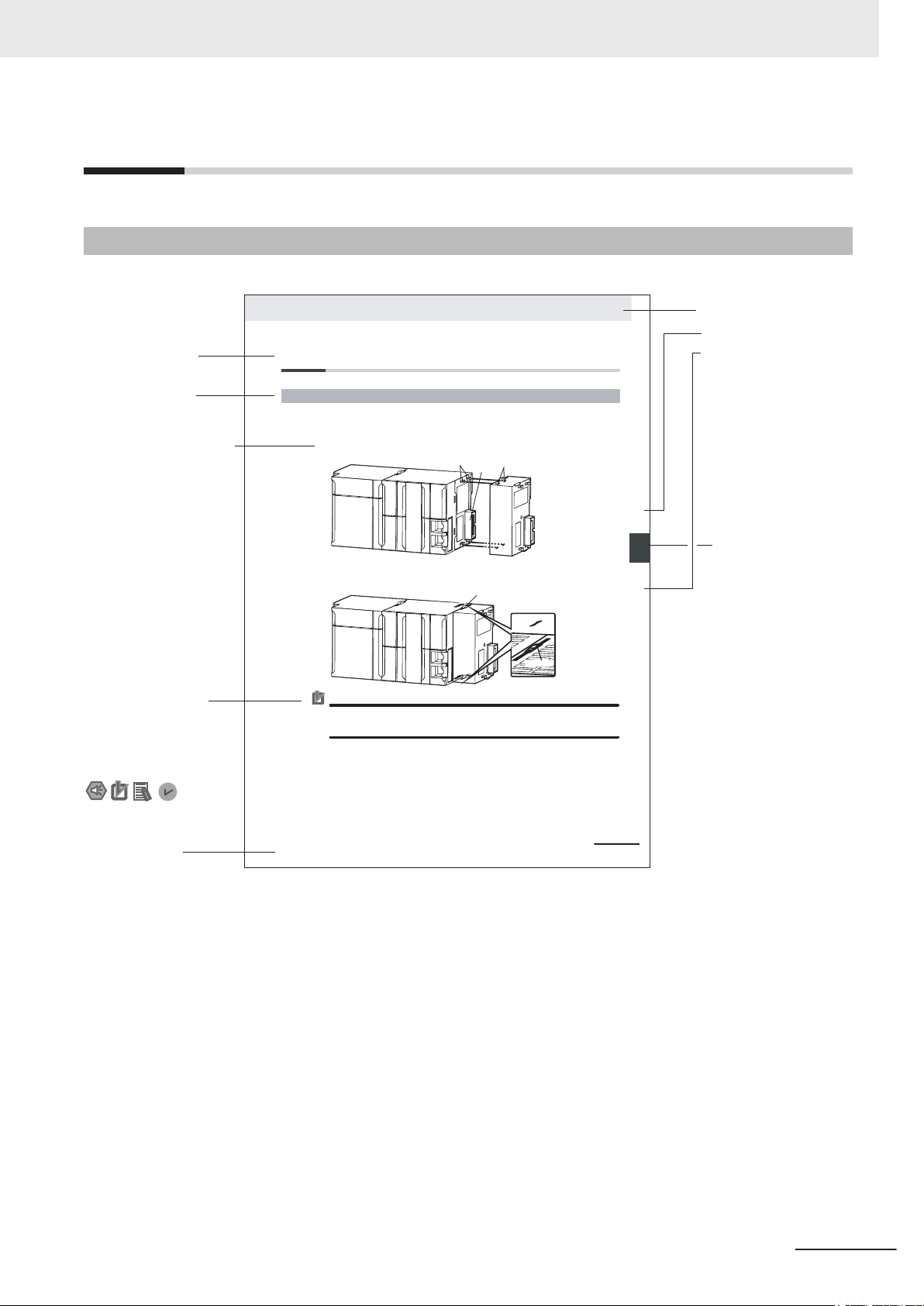
Level 1 heading
Level 2 heading
Level 3 heading
Level 2 heading
A step in a procedure
Manual name
Special information
Level 3 heading
Page tab
Gives the current
headings.
Indicates a procedure.
Icons indicate
precautions, additional
information, or reference
information.
Gives the number
of the main section.
This illustration is provided only as a sample. It may not literally appear in this manual.
The sliders on the tops and bottoms of the Power Supply Unit, C
PU Unit, I/O Units, Special I/O
Units, and CPU Bus Units must be completely locked (until they click into place) after connecting
the adjacent Unit connectors.
Page Structure
The following page structure is used in this manual.
Manual Structure
NX-series CPU Unit FINS Function User's Manual (W596)
7
Page 10

Manual Structure
Special Information
Special information in this manual is classified as follows:
Precautions for Safe Use
Precautions on what to do and what not to do to ensure safe usage of the product.
Precautions for Correct Use
Precautions on what to do and what not to do to ensure proper operation and performance.
Additional Information
Additional information to read as required.
This information is provided to increase understanding or make operation easier.
Version Information
Information on dif
and for dif
ferent versions of the Sysmac Studio is given.
ferences in specifications and functionality for Controller with different unit versions
Precaution on Terminology
In this manual, "download" refers to transferring data from the Sysmac Studio to the physical Control-
ler and "upload"
For the Sysmac Studio, "synchronization"
"synchronize" means to automatically compare the data for the Sysmac Studio on the computer with
the data in the physical Controller and transfer the data in the direction that is specified by the user.
refers to transferring data from the physical Controller to the Sysmac Studio.
is used to both "upload" and "download" data. Here,
8
NX-series CPU Unit FINS Function User's Manual (W596)
Page 11

CONTENTS
Introduction .............................................................................................................. 1
Intended Audience...........................................................................................................................................1
Applicable Products
Relevant Manuals..................................................................................................... 2
Terms and Conditions Agreement.......................................................................... 4
Warranty, Limitations of Liability ......................................................................................................................4
Application Considerations ..............................................................................................................................5
Disclaimers ......................................................................................................................................................5
Manual Structure...................................................................................................... 7
Page Structure.................................................................................................................................................7
Special Information .......................................................................................................................................... 8
Precaution on Terminology .............................................................................................................................. 8
CONTENTS
.........................................................................................................................................1
Safety Precautions................................................................................................. 11
Precautions for Safe Use ...................................................................................... 12
Precautions for Correct Use ................................................................................. 13
Regulations and Standards .................................................................................. 14
Versions.................................................................................................................. 15
Checking Versions.........................................................................................................................................15
Unit Versions of CPU Units and Sysmac Studio Versions.............................................................................18
Related Manuals..................................................................................................... 19
Revision History..................................................................................................... 20
Sections in this Manual ......................................................................................... 21
Section 1 FINS
1-1 Overview of FINS .................................................................................................................1 - 2
1-1-1 Server Function of FINS
1-1-2 Client Function of FINS .............................................................................................................1 - 2
1-2 Applicable CPU Units ..........................................................................................................1 - 3
1-3 System Configuration..........................................................................................................1 - 4
1-4 Relationship Between FINS Types and Units....................................................................1 - 5
1-5 Memory Used for CJ-series Units ......................................................................................1 - 6
1-5-1 Setting for the Memory Used for CJ-series Units ......................................................................1 - 6
1-5-2 Compatible Memory for CJ-series Units ...................................................................................1 - 6
............................................................................................................1 - 2
Section 2 Server Function
2-1 Overview of Server Function ..............................................................................................2 - 2
NX-series CPU Unit FINS Function User's Manual (W596)
9
Page 12

CONTENTS
2-2 FINS Commands Supported by NX-series CPU Units......................................................2 - 3
2-3 Setting of FINS Node Address of Built-in EtherNet/IP Port
2-4 FINS Routing Table Setting.................................................................................................2 - 7
2-5 FINS Write Protection Function..........................................................................................2 - 8
2-6 FINS Command Execution Condition ................................................................................2 - 9
Section 3 Client Function
Overview of Client Function..........................................................................................................3 - 2
FINS Communications Instructions .............................................................................................3 - 3
Send
...........................................................................................................................................................3 - 4
Rcv..............................................................................................................................................................3 - 8
SendCmd..................................................................................................................................................3 - 14
Section 4 Troubleshooting
.............................................2 - 5
4-1 Troubleshooting...................................................................................................................4 - 2
Appendices
A-1 Difference Between CS/CJ-series and NX-series in FINS Routing ................................ A - 2
A-1-1 Communication When 0 Is Specified for the Destination Network Address............................. A - 2
A-1-2 Operation of Routing Table during Clear All Memory operation............................................... A - 4
Index
10
NX-series CPU Unit FINS Function User's Manual (W596)
Page 13

Safety Precautions
Refer to the following manuals for safety precautions.
• NX-series CPU Unit Hardware User's Manual (Cat. No. W535)
• NX-series NX102 CPU Unit Hardware User's Manual (Cat. No. W593)
Safety Precautions
NX-series CPU Unit FINS Function User's Manual (W596)
11
Page 14

Precautions for Safe Use
Precautions for Safe Use
Refer to the following manuals for precautions for safe use.
• NX-series CPU Unit Hardware User's Manual (Cat. No. W535)
• NX-series NX102 CPU Unit Hardware User's Manual (Cat. No. W593)
12
NX-series CPU Unit FINS Function User's Manual (W596)
Page 15

Precautions for Correct Use
Refer to the following manuals for precautions for correct use.
• NX-series CPU Unit Hardware User's Manual (Cat. No. W535)
• NX-series NX102 CPU Unit Hardware User's Manual (Cat. No. W593)
Precautions for Correct Use
NX-series CPU Unit FINS Function User's Manual (W596)
13
Page 16

Regulations and Standards
Regulations and Standards
Refer to the following manuals for regulations and standards.
• NX-series CPU Unit Hardware User's Manual (Cat. No. W535)
• NX-series NX102 CPU Unit Hardware User's Manual (Cat. No. W593)
14
NX-series CPU Unit FINS Function User's Manual (W596)
Page 17
Versions
ID information indication
Lot number Serial number Unit version
MAC address Hardware revision
LOT No. DDMYY£ xxxx Ver.1.
££
PORT1 : ££££££££££££ HW Rev. £
PORT2 : ££££££££££££
Hardware revisions and unit versions are used to manage the hardware and software in NX-series
Units and EtherCAT slaves. The hardware revision or unit version is updated each time there is a
change in hardware or software specifications. Even when two Units or EtherCAT slaves have the
same model number, they will have functional or performance differences if they have different hard-
ware revisions or unit versions.
Checking Versions
You can check versions on the ID information indications or with the Sysmac Studio.
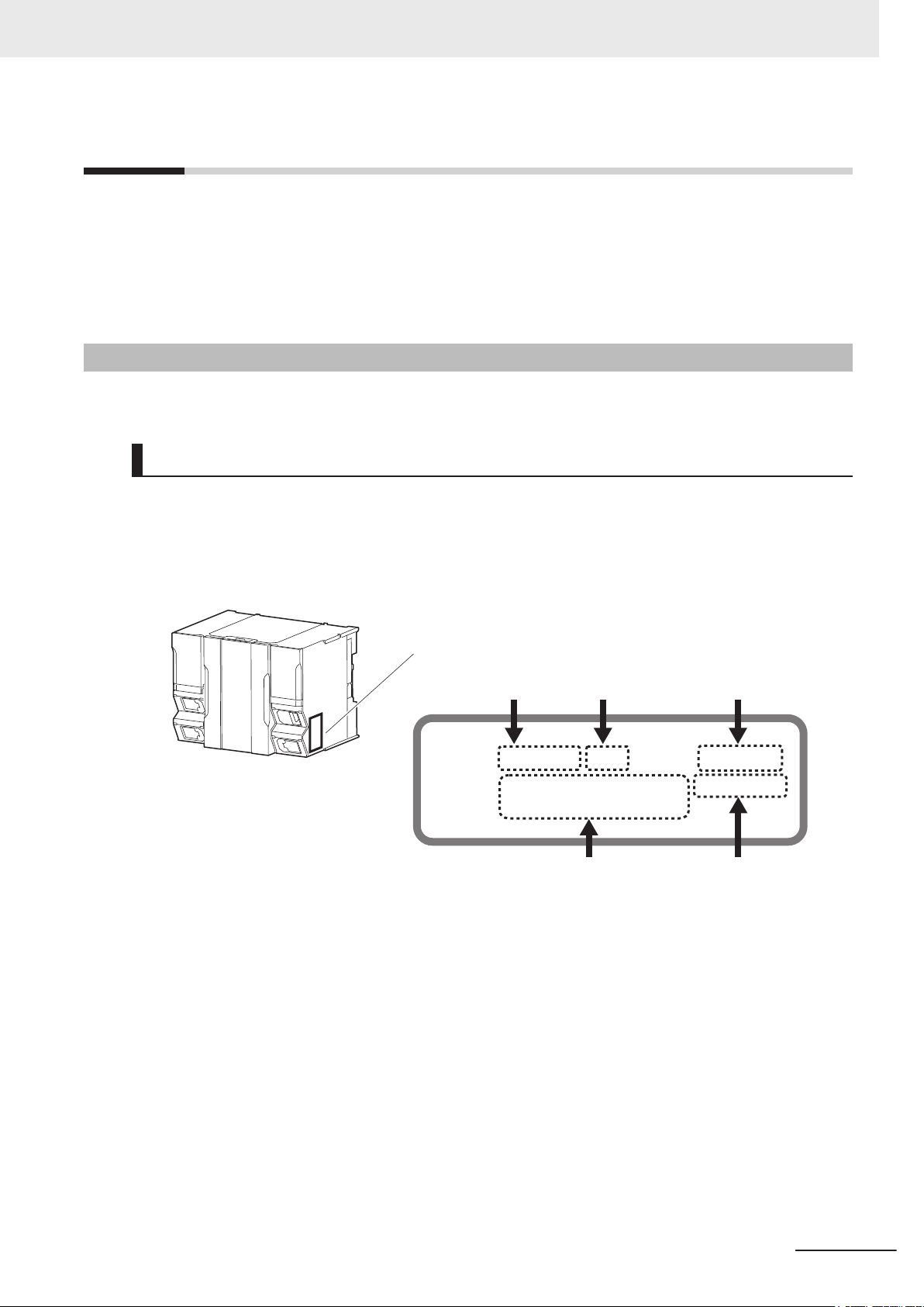
Checking Unit Versions on ID Information Indications
Versions
The unit version is given on the ID information indication on the side of the product.
For NX701
The ID information on an NX-series NX701-££££ CPU Unit is shown below.
Note The hardware revision is not displayed for the Unit whose hardware revision is blank.
NX-series CPU Unit FINS Function User's Manual (W596)
15
Page 18
ID Information Indication
Unit version Hardware revision
Lot number
Serial number
MAC address
LOT No. DDMYY£ xxxx
PORT1
££££££££££££
PORT2
££££££££££££
Ver.£.££ HW Rev.£
Versions
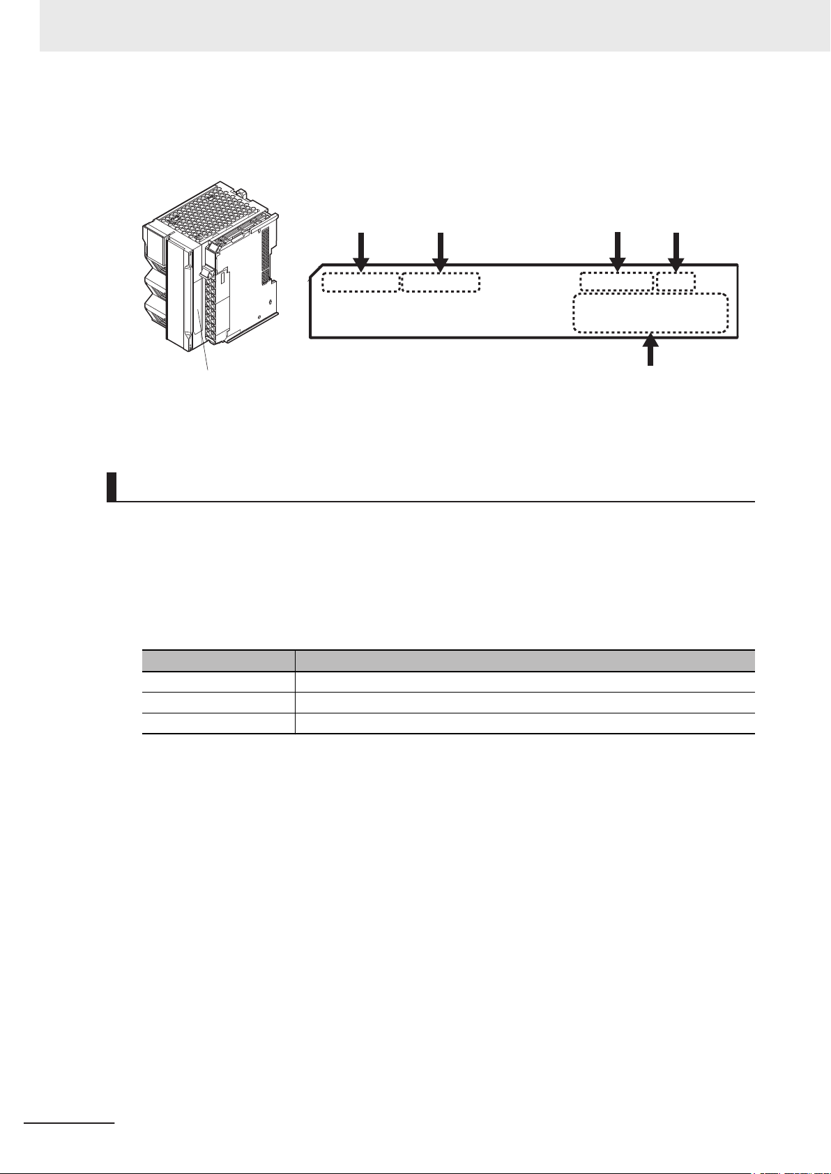
For NX102
The ID information on an NX-series NX102-££££ CPU Unit is shown below.
Note The hardware revision is not displayed for the Unit whose hardware revision is blank.
Checking Unit Versions with the Sysmac Studio
You can use the Sysmac Studio to check unit versions. The procedure is different for Units and for
EtherCA
T slaves.
Checking the Unit V
You can use the Production Information while the Sysmac Studio is online to check the unit version
of a Unit. You can do this for the following Units.
Model Unit for which unit version can be checked
NX701-££££
NX102-££££
NX1P2-££££
ersion of an NX-series CPU Unit
CPU Unit
CPU Unit and NX Unit on CPU Rack
CPU Unit, NX Unit on CPU Rack, and Option Boards
1 Right-click CPU Rack under Configurations and Setup - CPU/Expansion Racks in the Multi-
view Explorer and select Production Information.
The Production Information Dialog Box is displayed.
Changing Information Displayed in Production Information Dialog Box
1 Click the Show Detail
16
or
Show Outline Button at the lower right of the Production Information
Dialog Box.
The view will change between the production information details and outline.
NX-series CPU Unit FINS Function User's Manual (W596)
Page 19

Versions
Outline View Detail View
The information that is displayed is different for the Outline View and Detail View. The Detail
View displays the unit version, hardware revision, and various versions. The Outline View dis-
plays only the unit version.
Note The hardware revision is separated by “/” and displayed on the right of the hardware version. The
hardware revision is not displayed for the Unit that the hardware revision is in blank.
Checking the Unit Version of an EtherCAT Slave
You can use the Production Information while the Sysmac Studio is online to check the unit version
of an EtherCAT slave.
Use the following procedure to check the unit version.
1 Double-click EtherCAT
click EtherCAT under Configurations and Setup and select Edit from the menu.
The EtherCAT Tab Page is displayed for the Controller Configurations and Setup Layer.
under Configurations and Setup in the Multiview Explorer. Or, right-
2 Right-click the master on the EtherCAT Tab Page and select Display Production Information.
The Production Information Dialog Box is displayed.
The unit version is displayed after “Rev.”
Changing Information Displayed in Production Information Dialog Box
1 Click the
Dialog Box.
The view will change between the production information details and outline.
Show Detail or Show Outline Button at the lower right of the Production Information
Outline View Detail View
NX-series CPU Unit FINS Function User's Manual (W596)
17
Page 20

Versions
Unit Versions of CPU Units and Sysmac Studio Versions
The functions that are supported depend on the unit version of the NX-series CPU Unit. The version of
Sysmac Studio that supports the functions that were added for an upgrade is also required to use
those functions.
Refer to the NJ/NX-series CPU Unit Software User's Manual (Cat. No. W501)
tween the unit versions of the
are supported by each unit version.
CPU Units and the Sysmac Studio versions and for the functions that
for the relationship be-
18
NX-series CPU Unit FINS Function User's Manual (W596)
Page 21

Related Manuals
The following manual are related. Use these manuals for reference.
Manual name Cat. No. Model Application Contents
NX-series CPU Unit
Hardware User's Manual
NX-series
NX102 CPU Unit
Hardware
User
’
s Manual
NJ/NX-series CPU Unit
Software User
NX-series
CPU Unit
FINS Function
s Manual
User’
NJ/NX-series
T
roubleshooting Manual
Sysmac Studio Version 1
Operation Manual
CS/CJ-series
Ethernet unit
Application Construction
User's Manual
CS/CJ/CP/NSJ-series
Communications Commands
Reference Manual
’
s Manual
W535
W593
W501
W596
W503
W504 SYSMAC
W421 CS1W-ETN21
W342
NX701-££££
NX102-££££
NX701-££££
NX102-££££
NX1P2-££££
NJ501-££££
NJ301-££££
NJ101-££££
NX701-££20
NX102-££££
NX701-
NX102-££££
NX1P2-££££
NJ501-££££
NJ301-££££
NJ101-££££
-SE2£££
CJ1W-ETN21
CS1G/H-CPU
CS1D-CPU£££
CS1W
CJ1G/H-CPU£££
CJ1M-CPU££
CJ2H-CPU6£
CJ2M-CPU££
CJ1W-SCU££-V1
CP1H-£££££
CP1L-M/L£££
CP1E-£££D£
££££
-SC
£££-V1
Learning the basic
specifications of the
NX701 CPU Units,
including introductory
information, design-
ing, installation, and
maintenance.
Mainly hardware in-
formation is provided.
Learning the basic
specifications of the
NX102 CPU Units,
including introductory
information, design-
ing, installation, and
maintenance.
Mainly hardware in-
formation is provided.
Learning how to pro-
gram and set up an
NJ/NX-series CPU
Unit.
Mainly software infor-
mation is provided.
Using the FINS func-
tion of an NX-series
CPU Unit.
Learning about the
errors that may be
detected in an
NJ/NX-series Con-
troller
Learning about the
operating procedures
and functions of the
Sysmac Studio.
Using an Ethernet
unit
Learning the detailed
££
communication com-
mands for the
CS/CJ/CP-series
CPU Unit and NSJ-
series.
Related Manuals
An introduction to the entire NX701 system is
provided along with the following information on
the CPU Unit.
• Features and system configuration
• Introduction
• Part names and functions
• General specifications
• Installation and wiring
• Maintenance and inspection
An introduction to the entire NX102 system is
provided along with the following information on
the CPU Unit.
• Features and system configuration
• Introduction
• Part names and functions
• General specifications
• Installation and wiring
• Maintenance and Inspection
The following information is provided on a Con-
troller built with an NJ/NX-series CPU Unit.
• CPU Unit operation
• CPU Unit features
• Initial settings
• Programming based on IEC 61
specifications
Describes the FINS function of an NX-series CPU
Unit.
Concepts on managing errors that may be detect-
ed in an NJ/NX-series Controller and information
on individual errors are described.
.
Describes the operating procedures of the Sys-
mac Studio.
This manual describes the mail send function,
mail receive function, socket service function,
clock information automatic adjustment function,
FTP server function, and host application creation
of FINS communications.
This manual describes the C mode commands
and FINS commands for the CPU unit in detail.
131-3 language
NX-series CPU Unit FINS Function User's Manual (W596)
19
Page 22

W596-E1-01
Revision code
Cat. No.
Revision History
Revision History
A manual revision code appears as a suffix to the catalog number on the front and back covers of the
manual.
Revision
code
01 April 2018 Original production
Revision date Revised content
20
NX-series CPU Unit FINS Function User's Manual (W596)
Page 23

Sections in this Manual
1
2
3
4
A
I
1
2
3
4
A
I
FINS
Server Function
Client Function
Troubleshooting
Appendices
Index
Sections in this Manual
NX-series CPU Unit FINS Function User's Manual (W596)
21
Page 24

Sections in this Manual
22
NX-series CPU Unit FINS Function User's Manual (W596)
Page 25

FINS
1
This section describes an overview, a system configuration, and types of FINS.
1
1-1 Overview of FINS
1-1-1 Server Function of FINS ............................................................................... 1 - 2
1-1-2 Client Function of FINS................................................................................. 1 - 2
1-2 Applicable CPU Units .................................................................................. 1 - 3
1-3 System Configuration.................................................................................. 1 - 4
1-4 Relationship Between FINS Types and Units ............................................ 1 - 5
1-5 Memory Used for CJ-series Units............................................................... 1 - 6
1-5-1 Setting for the Memory Used for CJ-series Units ......................................... 1 - 6
1-5-2 Compatible Memory for CJ-series Units ....................................................... 1 - 6
.......................................................................................... 1 - 2
NX-series CPU Unit FINS Function User's Manual (W596)
1 - 1
Page 26

NX-series CPU Unit
Ethernet
FINS command
Response frame
Ethernet
FINS command
Response frame
NX-series CPU Unit
OMRON Unit
1 FINS
1-1
1-1-1
Overview of FINS
FINS is a command system for the message service that can be used commonly in OMRON network.
The FINS command system allows to read sent and received data, status etc. between a host comput-
er and an NX-series CPU Unit, and between an NX-series CPU Unit and an OMRON CPU Unit.
FINS provides server and client functions.
For details about the FINS frame format, refer to the SYSMAC CS/CJ/CP/NSJ-series Communications
Commands Reference Manual (Cat. No. W342).
Server Function of FINS
This function allows to receive FIN commands from external devices such as host computers or OM-
RON CPU Units and then to execute requested services.
1-1-2
1 - 2
Client Function of FINS
This function allows NX102 CPU Units to send and receive data to/from OMRON Units which is pro-
vided with Server Function of FINS.
NX-series CPU Unit FINS Function User's Manual (W596)
Page 27

1 FINS
1-2 Applicable CPU Units
1-2
Applicable CPU Units
FINS commands can be sent/received from/by the following CPU Units.
Unit name Model Server function Client function
NX7 Database Connection
CPU Unit
NX102 CPU Unit
NX1P2 CPU Unit
*1.
NX701-££00 does not support the Server Function of FINS and the Client Function of FINS.
*2. Only port 2 of the built-in EtherNet/IP ports supports FINS commands.
NX701-££20
NX102-££££
NX1P2-££££
*1*2
*2
Available Not available
Available Available
Not available Not available
Unit version of CPU
Unit
Version 1.16 or higher
1
NX-series CPU Unit FINS Function User's Manual (W596)
1 - 3
Page 28

Ethernet
FINS command
Built-in EtherNet/IP port
NX
-series CPU Unit
Or
CS/CJ/CP-series CPU Unit
NX-series CPU Unit
Computer software
1 FINS
1-3
System Configuration
System configuration is available on conditions that it must issue FIN commands received from exter-
nal computers and OMRON CPU Units and receive FINS commands through the built-in EtherNet/IP
port of the NX-series CPU Unit.
1 - 4
NX-series CPU Unit FINS Function User's Manual (W596)
Page 29

1 FINS
1-4 Relationship Between FINS
1-4
Relationship Between FINS Types and Units
The following shows the relationship between applicable FINS types and unit.
Item
FINS/UDP Usable or not Yes
Port number
FINS/TCP Usable or not Yes
Maximum number of connections
Port number
FINS communication service on
Ethernet
*1. This can be changed.
*2. This is total number of server and client connections.
Number of nodes 254
Message length Max. 2,012 bytes
NX701-££20 NX102-££££
*1
9600
*2
16
*1
9600
Units
Types and Units
1
NX-series CPU Unit FINS Function User's Manual (W596)
1 - 5
Page 30

1 FINS
1-5
1-5-1
1-5-2
Memory Used for CJ-series Units
The following describes how to set the memory used for the CJ-series Units and the area types of the
compatible memory used for CJ-series Units.
Setting for the Memory Used for CJ-series Units
For The NX701-££20 and NX102 CPU Unit
the Multiview Explorer of the Sysmac Studio.
Select
type and each address range of the memory used for CJ-series Units.
For details, refer to Sysmac Studio Version 1 Operation Manual (Cat. No. W504).
Configurations and Setup-Controller Setup, and then use Memory Settings to set the area
Compatible Memory for CJ-series Units
NX701-££20 and NX102 CPU Units are compatible with the following area types of the memory used
for CJ-series Units.
•
CIO Area
Work Area
•
• Holding Area
• Data Memory Area
• Expansion Memory Area
, the memory used for CJ-series Units can be set using
For details about the specifications of memory for the CJ Units, refer to NJ/NX-series CPU Unit
Software User's Manual (Cat. No. W501).
1 - 6
NX-series CPU Unit FINS Function User's Manual (W596)
Page 31

2
2
Server Function
This section describes a function that issues FINS commands supported by the NXseries CPU Unit and, reads and writes the memory used for CJ-series Units.
2-1 Overview of Server Function
2-2 FINS Commands Supported by NX-series CPU Units .............................. 2 - 3
2-3 Setting of FINS Node Address of Built-in EtherNet/IP Port...................... 2 - 5
2-4 FINS Routing Table Setting ......................................................................... 2 - 7
2-5 FINS Write Protection Function .................................................................. 2 - 8
2-6 FINS Command Execution Condition......................................................... 2 - 9
...................................................................... 2 - 2
NX-series CPU Unit FINS Function User's Manual (W596)
2 - 1
Page 32

2 Server Function
2-1
Overview of Server Function
The NX-series CPU Unit receives FINS commands issued from external devices such as host comput-
ers or CS/CJ/CP-series CPU Units on the Ethernet network and then can execute the requested serv-
ice.
2 - 2
NX-series CPU Unit FINS Function User's Manual (W596)
Page 33

2 Server Function
2-2 FINS Commands Supported by NX-ser-
2-2
FINS Commands Supported by NXseries CPU Units
This section describes FINS commands supported by the NX-series CPU Unit, restrictions, and execu-
tion conditions.
For details about each FINS command, refer to SYSMAC CS/CJ/CP/NSJ-series Communications
Commands Reference Manual (Cat. No. W342).
FINS Commands Supported by NX-series CPU Units and Restrictions
The following describes FINS commands supported by the NX-series CPU Units and restrictions when
they are used.
Command code
(Hex)
MR SR
01 01 MEMORY AREA READ Only areas that exist in the memory of CJ-series Units are acces-
01 02 MEMORY AREA WRITE
01 03 MEMORY AREA FILL
01 04 MULTIPLE MEMORY
01 05 MEMORY AREA
05 01 CPU UNIT DATA READ
06 01 CPU UNIT STATUS
07 01 CLOCK READ None
07 02 CLOCK WRITE
*1. Fixed values are returned for the following values.
• DIP switch information: Fixed at 0
• Program area size: Fixed at 14 hex.
• Timer/counter size: Fixed at 08 hex.
• Memory card type: SD Memory Card
• SD memory card size: SD Memory Card fixed at FFFF hex. when a memory card is inserted. Fixed at 00
hex. when a memory card is not inserted
• Remote I/O information: Fixed at 0
*2. Two pieces of information shown below are processed as error information of the NX-series.
• Fatal error information: A value of 0000 hex. is returned when the major fault level is normal. A value of
0001 hex. is returned when the major fault level is abnormal.
• Non-fatal error information: A value of 0000 hex. is returned when the partial fault level or minor fault level
is normal. A value of 0001 hex. is returned when the partial fault level or minor fault level is abnormal.
*3. All below values are returned fixed at 0.
"CPU status", "Battery presence", "Built-in flash memory access status", "Message presence", "Failure
code"
Command name Restrictions
sible.
AREA READ
TRANSFER
Only the following values can be read.
• CPU Unit model
• CPU Unit version
Only the following values can be read. *4 *4
READ
• Operation status
• Operating mode
fixed at 04 hex. (regardless of the presence status)
*1
*4
ies CPU Units
2
NX-series CPU Unit FINS Function User's Manual (W596)
2 - 3
Page 34

2 Server Function
*4. Sixteen ASCII code 20Hex (space) characters of below value are returned and can not be used.
"Error message"
2 - 4
NX-series CPU Unit FINS Function User's Manual (W596)
Page 35

2 Server Function
2-3 Setting of FINS Node Address of Built-in
2-3
Setting of FINS Node Address of Built-in EtherNet/IP Port
This FINS node address is necessary to identify a node in the FINS communication.
The following describes how to determine the FINS node address of the built-in EtherNet/IP port and
how to set the FINS node address from the Sysmac Studio.
IP address ⇔ FINS
node address conver-
sion method
Automatic generation
method
Combined method Set the FINS node address itself. Controller Setup - Built-in EtherNet/IP Port
IP address table method
*1. This may vary depending on the setting of IP address ⇔ FINS address conversion method for FINS/
UDP. T
Settings - FINS Settings - FINS/UDP - IP Address ⇔ FINS Address Conversion Method from the Multiview Explorer of the Sysmac Studio.
*1
o make the setting, select Configurations and Setup - Controller Setup - Built-in EtherNet/IP Port
FINS node address determina-
tion method
The least significant digits of the
IP address becomes the FINS
node address automatically.
Setting method from Sysmac Studio
Controller Setup Settings - TCP/IP Settings - IP Address
Settings
Settings Address Settings
FINS Settings - FINS Node
Built-in EtherNet/IP Port
EtherNet/IP Port
2
When the automatic generation method is selected, the least significant digit of the IP address is set
as the FINS node address.
When the combined method or IP address table method is selected, the value specified for the FINS
node address setting is the FINS node address.
NX-series CPU Unit FINS Function User's Manual (W596)
2 - 5
Page 36

2 Server Function
2 - 6
NX-series CPU Unit FINS Function User's Manual (W596)
Page 37

2 Server Function
2-4
FINS Routing Table Setting
The routing table is a table that is used to find the communication path of the FINS message when the
FINS communication service is in use.
The routing table consists of two types of tables: local network table and relay network table.
Here are the cases, where the setting of FINS routing table is required.
• When the FINS routing table is already set at one or more nodes in the same network and the FINS
message communications are performed, the local network table setting is required.
For details, refer to A-1 Difference Between CS/CJ-series and NX-series in FINS Routing on page
A - 2.
• When the FINS command is issued over the level of the FINS network, the relay network table set-
ting is required.
To set the FINS routing table, select Configurations and Setup - Controller Setup - Operation
Settings - FINS Settings from the Multiview Explorer of the Sysmac Studio.
2-4 FINS Routing Table Setting
2
NX-series CPU Unit FINS Function User's Manual (W596)
2 - 7
Page 38

2 Server Function
2-5
FINS Write Protection Function
When data is written into the CPU Unit using the FINS command, this data writing can be disabled so
that the data is not written into the memory of the CPU Unit.
This function is called the FINS write protection function.
The models that support the FINS write protection function are NX701-££20 and NX102-££££.
To set whether to use the write protection function select Configurations and Setup - Controller
Setup - Operation Settings - FINS Settings - Security Settings from the Multiview Explorer of the
Sysmac Studio.
Even when the FINS write protection function is enabled, the data reading from the CPU Unit is still
possible.
For details, refer to Sysmac Studio Version 1 Operation Manual (Cat. No. W504).
2 - 8
NX-series CPU Unit FINS Function User's Manual (W596)
Page 39

2 Server Function
2-6 FINS Command Execution Condition
2-6
FINS Command Execution Condition
The following describes the FINS command execution conditions.
Command code
(Hex)
MR SR RUN mode PROGRAM mode
01 01 MEMORY AREA READ Supported Supported Supported
01 02 MEMORY AREA WRITE Not supported
01 03 MEMORY AREA FILL Not supported
01 04 MULTIPLE MEMORY AREA
01 05 MEMORY AREA TRANS-
05 01 CPU UNIT DATA READ Supported
06 01 CPU UNIT STATUS READ Supported
07 01 CLOCK READ Supported
07 02 CLOCK WRITE Not supported
Command name
READ
FER
Execution condition
Write protection in proc-
ess
Supported
Not supported
2
NX-series CPU Unit FINS Function User's Manual (W596)
2 - 9
Page 40

2 Server Function
2 - 10
NX-series CPU Unit FINS Function User's Manual (W596)
Page 41

Client Function
3
3
This section describes the instructions that issue the FINS command from the NX102
CPU Unit for OMRON Unit provided with the FINS server function and then send and
receive data.
Overview of Client Function.................................................................................. 3 - 2
FINS Communications Instructions
...................................................................... 3 - 3
NX-series CPU Unit FINS Function User's Manual (W596)
3 - 1
Page 42

3 Client Function
Overview of Client Function
FINS communication instructions is a set of instructions, which allows to control data send/receive,
mode change etc. as required, for various types of units such as CPU Units and CPU Special Units on
the network or CPU Rack.
These instructions are executed over multiple cycles and perform the communication non-synchron-
ized with the cycle.
3 - 2
NX-series CPU Unit FINS Function User's Manual (W596)
Page 43

FINS Communications Instructions
FINS Communications Instructions
3
Instructions Name Page
Send Send to Network page 3 - 4
Rcv Receive from Network page 3 - 8
SendCmd Send Command page 3 - 14
NX-series CPU Unit FINS Function User's Manual (W596)
3 - 3
Page 44

Send
Send
_instance
Execute
DstNetAdr
Done
CommPort
SrcDat
SendSize
DstCh
Option
Error
ErrorID
DstArea
Busy
ErrorIDEx
3 Client Function
Send
Sends data to a node on the network.
Instruction Name
Send
Send to Network
FB/
FUN
FB
Graphic expression ST expression
Send_instance(Execute, DstNetAdr, CommPort, SrcDat, SendSize, DstArea, DstCh, Option,
Done, Busy
DEx);
Variable
Name
DstNetAdr
CommPort
SrcDat[] array
SendSize Number of send words
DstArea
DstCh CH at send destination
Option Response
*1. If you omit an input parameter, the default value is not applied. A building error will occur.
*2. This may vary depending on the network type.
Network address at
send destination
Designation of port at
send destination
First element of array
at send destination
Area at send destination
3 - 4
Input/
output
Input
Contents Valid range Unit
Specifies the network
address and node address at send destination
Specifies the serial
port at send destination
Beginning of data (array) to be sent
Specifies the number
of words in the send
data
Specifies the area type
at send destination
Specifies the first ch at
send destination
Specifies response
monitoring and resending
NX-series CPU Unit FINS Function User's Manual (W596)
--- --- ---
_NONE --- _NONE
16#0000 to
16#FFFF
0 to Max. data
*2
length
_CIO
_WR
_HR
_TIMER
_COUNTER
_DM
_EM0
⋮
_EM18
0 to 32,767 ch 0
--- --- ---
, Error, ErrorID, ErrorI-
Initial
value
---
Word 1
--- _DM
*1
Page 45

3 Client Function
LINT
Real
num-
bers
REAL
Times, durations,
dates, and text strings
LREAL
TIME
Boo
lean
BOOL
DstNetAdr Refer to Function on page 3 - 5 for details on the structure _sDNET_ADR.
CommPort For enumeration_ePORT enumerator, refer to Function on page 3 - 5.
SrcDat[] array
SendSize
DstArea For enumeration_eAREA enumerator
DstCh
Option Refer to Function on page
Bit strings Integers
DWORD
BYTE
WORD
OK
LWORD
USINT
OK
OK
UINT
UDINT
3 -
ULINT
SINT
5 for details on the structure _sRESPONSE.
DINT
INT
, refer to Function on page 3 - 5.
Function
When Execute changes from F
specified by DstNetAdr, CommPort, DstArea, and DstCh.
The data type of DstNetAdr is structure_sDNET_ADR. The specifications are shown below.
ALSE to TRUE, SrcDat[] is written to the area at the send destination
DATE
TOD
DT
STRING
FINS Communications Instructions
3
Send
Variable Name Contents Data type Valid range Unit
Network ad-
DstNetAdr
NetNo
NodeNo Node address Node address USINT
UnitNo Unit address Unit address BYTE
dress at send
destination
Network address
The data type of CommPort is enumeration_ePORT
Network address at
send destination
Network address USINT 0 to 127
_sDNET_AD
R
--- --- ---
Depends on
the data type
Depends on
the data type
.
The meaning of the enumerator of enumeration_ePORT is as follows.
Enumerator Meaning
_NONE The send destination is not a serial port (host link mode).
The data type of DstArea is enumeration_eAREA.
The meaning of the enumerator of enumeration_eAREA is as follows.
Enumerator Meaning
_CIO Core I/O Area, Work Area, etc.
_WR Work Area
_HR Holding Area
_TIMER Timer Area
_COUNTER Counter Area
_DM Data Memory Area
_EM0 0 bank area of Expansion Memory Area
⋮ ⋮
Initial
value
0
---
16#00
NX-series CPU Unit FINS Function User's Manual (W596)
3 - 5
Page 46

3 Client Function
Enumerator Meaning
_EM18 24 bank area of Expansion Memory Area
The data type of Option is structure_sRESPONSE. The specifications are shown below.
Variable Name Contents Data type Valid range Unit
Option Response
isNonResp No response
TimeOut Timeout Time
Retry Retry count Retry count USINT 0 to 15
Response monitoring
and retry specifications
TRUE: Response is not
required.
FALSE: Response is required.
Timeout time
0: 2.0 s
If no response is returned within the timeout time Option.TimeOut
Necessary Flag Option.isNonResp is FALSE, the command is retried until the response is returned.
The retry count is specified by Option.Retry.
The timeout time is Option.TimeOut x 0.1 s. However, when the value of Option.TimeOut is 0, the
timeout time becomes 2.0 s. The initial value of Option.TimeOut is also 2.0 s.
Related System-defined Variables
_sRESPONSE
BOOL
UINT 0.1 s
--- --- ---
Depends on
the data type
---
Cou
nt
when the value of the Response Not
Initial
value
FALSE
20
(2.0 s)
0
Name Meaning
_Port_numUsingPort
_Port_isAvailable
Number of Used
Ports
Network Communications Instruction
Enabled Flag
Precautions for Correct Use
• This instruction can be executed only when there is an available port. Therefore, use the system-
defined variable _Port_isAvailable
execution condition for the instruction.
• The command is not sent if the value of SendSize is 0. When the instruction is executed, the value
of Done changes to TRUE.
• During execution of this instruction, set Option.Retry to a value other than 0 by considering the case
when the send message or response is lost due to noise that occurs during communication. If no
response is returned within Option.TimeOut, it is recommended to retry the process.
• When this instruction is written in the ST program, make sure that the instruction is executed for
each task period during execution of this instruction. If this instruction is not executed every task pe-
riod, the normal process may not be performed.
• This instruction cannot be used on the event task. An error occurs during compiling.
• An error occurs in the following cases. Error will change to TRUE.
a) A member of DstNetAdr is outside of its range.
Data
type
USINT This is the number of ports that are currently used.
BOOL
TRUE: A port is available.
FALSE: A port is not available.
Description
(Network Communications Instruction Enabled Flag) in an N.O.
3 - 6
NX-series CPU Unit FINS Function User's Manual (W596)
Page 47

b) SendSize, DstArea, or DstCh is outside of its range.
c) A member of Option is outside of its range.
d) The value of SendSize exceeds the size of SrcDat[].
e) The value of _Port_isAvailable is F
f) Communications fail.
Sample Programming
3 Client Function
FINS Communications Instructions
ALSE.
Refer to Sample Programming on page 3 - 1
1 of the Rcv instruction.
3
Send
NX-series CPU Unit FINS Function User's Manual (W596)
3 - 7
Page 48

Rcv
Rcv
_instance
Execute
SrcNetAdr
Done
CommPort
SrcArea
SrcCh
Option
Error
ErrorID
RcvSize
Busy
ErrorIDEx
DstDat
3 Client Function
Rcv
Requests a node on the network to send and receives data.
Instruction Name
Rcv
Receive from
Network
FB/
FUN
FB
Graphic expression ST expression
Rcv_instance(Execute, SrcNetAdr,
CommPort, SrcArea, SrcCh,
RcvSize, DstDat, Option, Done,
Busy, Error
Variable
Name
SrcNetAdr
CommPort
SrcArea Data source area
SrcCh Data source CH
RcvSize
Option Response Specifies response
DstDat[] array
*1. This may vary depending on the network type.
*2. If you omit an input parameter, the default value is not applied. A building error will occur.
Network address at
source
Designation of port at
receive destination
Number of receive
words
First element of receive array
3 - 8
Input/
output
Input
Input/
output
Contents Valid range Unit
Specifies the network
address and node address at send source
Selects the serial port
at receive destination
Specifies the area type
at send source
Specifies the first ch at
send source
Specifies the number
of words in the receive
data.
monitoring and resending
Beginning of data (array) to be received
NX-series CPU Unit FINS Function User's Manual (W596)
--- --- ---
_NONE --- _NONE
_CIO
_WR
_HR
_TIMER
_COUNTER
_DM
_EM0
⋮
_EM18
0 to 32,767 ch 0
0 to Max. data
*1
length
--- --- ---
16#0000 to
16#FFFF
, ErrorID, ErrorIDEx);
Initial
value
--- _DM
Word 1
---
*2
Page 49

3 Client Function
LINT
Real
num-
bers
REAL
Times, durations,
dates and text strings
LREAL
TIME
Boo
lean
BOOL
SrcNetAdr Refer to Function on page 3 - 9 for details on the structure _sDNET_ADR.
CommPort For enumeration_ePORT enumerator, refer to Function on page 3 - 9.
SrcArea For enumeration_eAREA enumerator
SrcCh
RcvSize
Option Refer to Function on page
DstDat[] array
Bit strings Integers
DWORD
BYTE
WORD
OK
LWORD
USINT
OK
OK
UINT
UDINT
3 -
ULINT
SINT
9 for details on the structure _sRESPONSE.
DINT
INT
, refer to Function on page 3 - 9.
Function
When Execute changes from F
data specified by SrcArea and SrcCh.
The received data is stored in DstDat[].
ALSE to TRUE, SrcNetAdr and CommPort are requested to send the
DATE
TOD
DT
STRING
FINS Communications Instructions
3
Rcv
The data type of SrcNetAdr is structure_sDNET_ADR. The specifications are shown below.
Variable Name Contents Data type Valid range Unit
Network ad-
SrcNetAdr
NetNo
NodeNo Node address Node address USINT
UnitNo Unit address Unit address BYTE
dress at
source
Network address
The data type of CommPort is enumeration_ePORT
Specifies the network
address and node address at send source
Network address USINT 0 to 127
_sDNET_AD
R
--- --- ---
Depends on
data type.
Depends on
data type.
.
---
The meaning of the enumerator of enumeration_ePORT is as follows.
Enumerator Meaning
_NONE The send destination is not a serial port (host link mode).
The data type of SrcArea is enumeration_eAREA.
The meaning of the enumerator of enumeration_eAREA is as follows.
Initial
value
0
16#00
Enumerator Meaning
_CIO Core I/O Area, Work Area, etc.
_WR Work Area
_HR Holding Area
_TIMER Timer Area
_COUNTER Counter Area
_DM Data Memory Area
_EM0 0 bank area of Expansion Memory Area
NX-series CPU Unit FINS Function User's Manual (W596)
3 - 9
Page 50

3 Client Function
Enumerator Meaning
⋮ ⋮
_EM18 24 bank area of Expansion Memory Area
The data type of Option is structure_sRESPONSE. The specifications are shown below.
Variable Name Contents Data type Valid range Unit
Option Response
isNonResp No response
TimeOut Timeout Time
Retry Retry count Retry count USINT 0 to 15
Response monitoring
and retry specifications
TRUE: Response is not
required.
FALSE: Response is required.
Timeout time
0: 2.0 s
If no response is returned within the timeout time Option.T
Necessary Flag Option.isNonResp is FALSE, the command is retried until the response is returned.
The retry count is specified by Option.Retry.
The timeout time is Option.TimeOut x 0.1 s. However, when the value of Option.TimeOut is 0, the
timeout time becomes 2.0 s. The initial value of Option.TimeOut is also 2.0 s.
Related System-defined Variables
_sRESPONSE
BOOL
UINT 0.1 s
imeOut
--- --- ---
Depends on
data type.
---
Cou
nt
when the value of the Response Not
Initial
value
FALSE
20
(2.0 s)
0
Name Meaning
_Port_numUsingPort
_Port_isAvailable
Number of Used
Ports
Network Communications Instruction
Enabled Flag
Precautions for Correct Use
• This instruction can be executed only when there is an available port. Therefore, use the system-
defined variable _Port_isAvailable (Network Communications Instruction Enabled Flag) in an N.O.
execution condition for the instruction.
• The command is not sent if the value of RcvSize is 0. When the instruction is executed, the value of
Done changes to TRUE.
• During execution of this instruction, set Option.Retry to a value other than 0 by considering the case
when the send message or response is lost due to noise that occurs during communication. If no
response is returned within Option.TimeOut, it is recommended to retry the process.
• When this instruction is written in the ST program, make sure that the instruction is executed for
each task period during execution of this instruction. If this instruction is not executed every task pe-
riod, the normal process may not be performed.
• This instruction cannot be used on the event task. An error occurs during compiling.
• An error occurs in the following cases. Error will change to TRUE.
Data
type
USINT This is the number of ports that are currently used.
BOOL
TRUE: A port is available.
FALSE: A port is not available.
Description
3 - 10
NX-series CPU Unit FINS Function User's Manual (W596)
Page 51

a) A member of SrcNetAdr is outside of its range.
Send “12345678”
Ethernet cable
Receive “12345678”
Node address 1
Node address 2
b) Broadcasting (SrcNetAdr.NodeNo.=255) is set.
c) Any of SrcArea, SrcCh, and RcvSize is outside of its range.
d) The value of RcvSize exceeds the size of DstDat[].
e) The data type that is not supported is specified for DstDat[].
f) A member of Option is outside of its range.
g) Option.isNonResp is TRUE and this instruction is executed.
h) The value of _Port_isAvailable is F
i) Communications fail.
Sample Programming
A 2CH data write command is sent to DM100 of network No. 0, node No. 2, and Unit No. 0. Then, the
2CH data read command is sent from DM100.
3 Client Function
FINS Communications Instructions
ALSE.
3
Rcv
ST
Inter-
nal
varia-
ble
Name Data type Initial value Comment
Trigger BOOL FALSE Execution condition
DoFinsTrigger BOOL FALSE Processing
SendExecute BOOL FALSE Send instruction execution flag
RcvExecute BOOL FALSE Rcv instruction execution flag
State SINT 0 Sample programming status
InDNetAdr _sDNET_ADR NetNo:=0, NodeNo:=0,
UnitNo:=16#0
InOption _sRESPONSE isNonResp:=FALSE,
imeOut:=0, Retry:=0
T
SrcDat
DstDat ARRAY [0..1] OF
SendInstance Send Send instance
RcvInstance Rcv Rcv instance
ARRAY [0..1] OF
WORD
WORD
[2(16#0)] Send data
[2(16#0)] Receive data
Network address at send destination
Response
NX-series CPU Unit FINS Function User's Manual (W596)
3 - 11
Page 52

3 Client Function
External variable Name Data type Comment
IF ( (Trigger=TRUE) AND (DoFinsTrigger=FALSE) AND (_Port_isAvailable=TRUE) ) THEN
State:= 1;
DoFinsTrigger:=TRUE;
SendExecute := FALSE; // Send execution status
RcvExecute := FALSE; // Rcv execution status
InDNetAdr.NetNo :=USINT#0; // Set network address.
InDNetAdr.NodeNo :=USINT#2;
InDNetAdr.UnitNo :=BYTE#16#0;
InOption.isNonResp :=FALSE; // Set
InOption.TimeOut :=UINT#20;
InOption.Retry :=USINT#2;
SrcDat[0] :=WORD#16#1234; // Set command array.
SrcDat[1] :=WORD#16#5678;
END_IF;
_Port_isAvailable BOOL Network Communications Instruction Enabled Flag
IF (DoFinsTrigger=TRUE) THEN
SendInstance( Execute := SendExecute,
DstNetAdr := InDNetAdr,
CommPort := _NONE,
SrcDat := SrcDat[0],
SendSize := 2,
DstArea := _DM,
DstCh := 100,
Option := InOption);
RcvInstance ( Execute := RcvExecute,
SrcNetAdr := InDNetAdr,
CommPort := _NONE,
SrcArea := _DM,
SrcCh := 100,
RcvSize := 2,
DstDat := DstDat[0],
Option := InOption);
CASE State OF
1: // Execute Send.
SendExecute := TRUE;
IF (SendInstance.Done=TRUE) THEN
State := 2;
ELSIF (SendInstance.Error=TRUE) THEN
State := 99;
END_IF;
3 - 12
NX-series CPU Unit FINS Function User's Manual (W596)
Page 53

2: // Execute Rcv.
RcvExecute := TRUE;
IF (RcvInstance.Done=TRUE) THEN
State := 3;
ELSIF (RcvInstance.Error=TRUE) THEN
State := 99;
END_IF;
3: // Normal processing
Trigger := FALSE;
DoFinsTrigger:=FALSE;
99: // Abnormal processing
Trigger := FALSE;
DoFinsTrigger:=FALSE;
END_CASE;
END_IF;
3 Client Function
FINS Communications Instructions
3
Rcv
NX-series CPU Unit FINS Function User's Manual (W596)
3 - 13
Page 54

SendCmd
SendCmd
_instance
Execute
DstNetAdr
Done
CommPort
CmdDat
Option
Error
ErrorID
CmdSize
Busy
ErrorIDEx
RespDat
3 Client Function
SendCmd
Issues a desired command and receives a response.
Instruction Name
SendCmd
Send Command
FB/
FUN
FB
Graphic expression ST expression
SendCmd_instance(Execute,
DstNetAdr, CommPort, CmdDat,
CmdSize, RespDat, Option, Done,
Busy
, Error, ErrorID, ErrorIDEx);
Variables
Meaning I/O Description Valid range Unit Default
DstNetAdr
CommPort Destination serial port Destination serial port _NONE _NONE
CmdDat[]
(array)
CmdSize Command data size Command data size
Option Response
RespDat[]
(array)
*1. If you omit an input parameter, the default value is not applied. A building error will occur.
*2. This may vary depending on the network type.
Destination network
address
Command array Command to send
Response storage array
Input
In-out
Destination network
address
Response monitoring
and retry specifications
Array to store response
---
---
Depends on data type.
0 to max. data
*2
length
--- --- ---
Depends on data type.
Bytes 2
--- ---
---
*1
LINT
Real
num-
bers
REAL
Times, durations,
dates, and text strings
LREAL
TIME
15.
Boo
lean
BOOL
DstNetAdr Refer to Function on page 3 - 15 for details on the structure _sDNET_ADR.
CommPort For enumeration_ePORT enumerator, refer to Function on page 3 -
CmdDat[]
(array)
CmdSize
Option Refer to Function on page 3 - 15
RespDat[]
(array)
3 - 14
Bit strings Integers
DWORD
BYTE
OK
OK
WORD
LWORD
USINT
OK
UINT
UDINT
ULINT
SINT
for details on the structure _sRESPONSE.
DINT
INT
NX-series CPU Unit FINS Function User's Manual (W596)
DATE
TOD
STRING
DT
Page 55

Function
3 Client Function
The SendCmd instruction sends the contents of command array CmdDat[] to the destination specified
with destination network address DstNetAdr and destination serial port CommPort.
The command data size CmdSize
specifies how many elements of CmdDat[] contain the command.
The response that is returned is stored in response storage array RespDat[].
The data type of
Name Meaning Description Data type Valid range Unit Default
DstNetAdr
NetNo
NodeNo Node address Node address USINT
UnitNo Unit address Unit address BYTE
The data type of CommPort is enumerated type _ePORT
DstNetAdr is structure _sDNET_ADR. The specifications are as follows:
Destination
network address
Network address
Destination network address
Network address USINT 0 to 127
_sDNET_AD
R
--- --- ---
Depends on
data type.
Depends on
data type.
.
0
---
16#00
The meanings of the enumerators of enumerated type _ePORT are as follows:
Enumerators Meaning
_NONE The destination is not a serial port in Host Link Mode.
FINS Communications Instructions
3
SendCmd
The data type of Option is structure _sRESPONSE. The specifications are as follows:
Name Meaning Description Data type Valid range Unit Default
Option Response
isNonResp No response
TimeOut Timeout time
Retry Retry count Retry count USINT 0 to 15
Response monitoring
and retry specifications
TRUE: Response is not
required.
FALSE: Response is required.
Timeout time
0: 2.0 s
If no response is returned within the timeout time Option.TimeOut
_sRESPONSE
BOOL
UINT 0.1 s
--- --- ---
Depends on
data type.
---
Time
s
when the value of the Response Not
FALSE
20
(2.0 s)
0
Necessary Flag Option.isNonResp is FALSE, the command is retried until the response is returned.
The retry count is specified by Option.Retry.
The timeout time is Option.TimeOut multiplied by 0.1 s. However, if the value of Option.TimeOut is 0,
the timeout time is 2.0 s. The default value of Option.TimeOut is 2.0 s.
NX-series CPU Unit FINS Function User's Manual (W596)
3 - 15
Page 56

3 Client Function
Related System-defined Variables
Name Meaning
_Port_numUsingPort
_Port_isAvailable
Number of Used
Ports
Network Communications Instruction
Enabled Flag
Precautions for Correct Use
• This instruction can be executed only when there is an available port. Therefore, use the system-
defined variable _Port_isAvailable
execution condition for the instruction.
• The command is not sent if the value of CmdSize is 0. When the instruction is executed, the value of
Done changes to TRUE.
• During execution of this instruction, set Option.Retry to a value other than 0 by considering the case
when the send message or response is lost due to noise that occurs during communication. If no
response is returned within Option.TimeOut, it is recommended to retry the process.
• When this instruction is written in the ST program, make sure that the instruction is executed for
each task period during execution of this instruction. If this instruction is not executed every task pe-
riod, the normal process may not be performed.
• This instruction cannot be used on the event task. An error occurs during compiling.
• An error occurs in the following cases. Error will change to TRUE.
a) A member of DstNetAdr is outside of its range.
b) CmdSize is outside of its range.
c) The value of CmdSize exceeds the size of CmdDat[].
d) A member of Option is outside of its range.
e) The response size exceeds the size of RespDat[].
f) The value of _Port_isAvailable is FALSE.
g) Communications fail.
Data
type
USINT This is the number of ports that are currently used.
BOOL
TRUE: A port is available.
ALSE: A port is not available.
F
Description
(Network Communications Instruction Enabled Flag) in an N.O.
3 - 16
NX-series CPU Unit FINS Function User's Manual (W596)
Page 57

Sample Programming
Ethernet cable
Node address 1
Node address 2 Unit No. 0
CPU UNIT DATA READ
3 Client Function
In this sample, the SendCmd instruction sends CPU UNIT DATA READ command from the network
No. 0, node No. 2, Unit No. 0 and receives the data.
ST
Internal
V
aria-
bles
Name Data type Initial value Comment
rigger BOOL FALSE Execution condition
T
DoFinsTrigger BOOL FALSE Processing
SendCmdExecute BOOL FALSE SendCmd instruction execu-
tion flag
State SINT 0 Sample programming status
InDNetAdr _sDNET_ADR NetNo:=0, NodeNo:=0,
UnitNo:=16#0
InOption _sRESPONSE isNonResp:=FALSE,
imeOut:=0, Retry:=0
T
CmdDat ARRA
RespDat ARRAY[0..1023] OF
SendCmdInstance SendCmd SendCmd instance
Y[0..1] OF
BYTE
BYTE
[2(16#0)] Send data
[1024(16#0)] Receive data
Network address at send
destination
Response
FINS Communications Instructions
3
SendCmd
External variable Name Data type Comment
_Port_isAvailable BOOL Network Communications Instruction Enabled Flag
IF ( (Trigger=TRUE) AND (DoFinsTrigger=FALSE) AND (_Port_isAvailable=TRUE) ) THEN
State:= 1;
DoFinsTrigger:=TRUE;
SendCmdExecute := FALSE; // Send execution status
InDNetAdr.NetNo :=USINT#0; // Set network address.
InDNetAdr.NodeNo :=USINT#2;
InDNetAdr.UnitNo :=BYTE#16#0;
InOption.isNonResp :=FALSE; // Set response.
InOption.TimeOut :=UINT#20;
InOption.Retry :=USINT#2;
NX-series CPU Unit FINS Function User's Manual (W596)
3 - 17
Page 58

3 Client Function
CmdDat[0] :=BYTE#16#05; // Set command array.
CmdDat[1] :=BYTE#16#01;
END_IF;
IF (DoFinsTrigger=TRUE) THEN
SendCmdInstance( Execute :=SendCmdExecute,
DstNetAdr:=InDNetAdr,
CommPort :=_NONE,
CmdDat := CmdDat [0],
CmdSize :=UINT#2,
RespDat := RespDat [0],
Option :=InOption);
CASE State OF
1: // Execute SendCmd.
SendCmdExecute := TRUE;
IF (SendCmdInstance.Done=TRUE) THEN
State := 2;
ELSIF (SendCmdInstance.Error=TRUE) THEN
State := 99;
END_IF;
2: // Normal processing
Trigger := FALSE;
DoFinsTrigger:=FALSE;
99: // Abnormal processing
Trigger := FALSE;
DoFinsTrigger:=FALSE;
END_CASE;
END_IF;
3 - 18
NX-series CPU Unit FINS Function User's Manual (W596)
Page 59

Troubleshooting
This section describes the errors that may occur during communications with CPU
Units.
4
4
4-1 T
roubleshooting ........................................................................................... 4 - 2
NX-series CPU Unit FINS Function User's Manual (W596)
4 - 1
Page 60

4 Troubleshooting
4-1
Troubleshooting
Refer to the End Codes in 5-1 Command Lists of SYSMAC CS/CJ/CP/NSJ-series Communications
Commands Reference Manual (Cat. No. W342) for details about the errors that may occur during
communications with CPU Units.
Refer to the manual of each relevant unit for details about the errors that may occur during communi-
cations with other OMRON Units.
4 - 2
NX-series CPU Unit FINS Function User's Manual (W596)
Page 61

Appendices
A
A-1 Difference Between CS/CJ-series and NX-series in FINS Routing......... A - 2
A-1-1 Communication When 0
dress.............................................................................................................. A - 2
A-1-2 Operation of Routing Table during Clear All Memory operation ...................A - 4
Is Specified for the Destination Network Ad-
A
NX-series CPU Unit FINS Function User's Manual (W596)
A - 1
Page 62

Appendices
A-1
A-1-1
Difference Between CS/CJ-series and
NX-series in FINS Routing
The FINS routing specification settings in the NX-series CPU Units differ from those in the CS/CJ-ser-
ies CPU Units by the following points:
• Communication when 0 is specified for the destination network address
• Operation of the routing table during Clear All Memory operation.
Communication When 0 Is Specified for the Destination Network
Address
The communication may vary depending on the CPU Unit as described below.
CPU Unit Operation
NX-series Routing of the network of the built-in EtherNet/IP port.
CS/CJ-series Routing of the network of the Communications Unit that has the smallest unit number among the
installed CS/CJ-series Special Units.
A - 2
NX-series CPU Unit FINS Function User's Manual (W596)
Page 63

FINS command
EtherNet/IP Unit (Unit number 0)
DeviceNet Unit (Unit number 1)
Controller Link Unit (Unit number 2)
CJ-series
CPU Unit
No settings for the
local network table
Unit number
0
1 2
1
Local network table
Network
address
*1
Ethernet
FINS command
Response frame
NX-series CPU Unit
CS/CJ-series CPU Unit
Unit number 0
Unit number 1
Appendices
Additional Information
For the CS/CJ-series CPU Units, the FINS command is issued to the network of the FINS network Communications Unit that has the smallest unit number.
A-1 Difference Between CS/CJ-series and NX-series in FINS Routing
*1. When the FINS command specified with network address 0 and node address n is issued to a CPU
Unit with no local network table specified, the FINS command is issued to the FINS network of the
lowest unit number.
When the opposite unit is the CS/CJ-series CPU Unit and 0 is specified for the destination network address, the communication may or may not be possible as described below.
Communication is possible when network number 0 is specified
• When only one FINS network Communications Unit is connected to the opposite CS/CJ-series CPU Unit.
• When multiple FINS network Communications Units are connected to the opposite CS/CJseries CPU Units, and the FINS network Communications Unit is connected to the CS/CJseries CPU Unit that has the smallest unit number.
In this case, the routing table setting is not required for the NX-series CPU Unit.
A
A-1-1 Communication When 0 Is Specified for the Destination Network Address
NX-series CPU Unit FINS Function User's Manual (W596)
Communication is not possible when network number 0 is specified
• When multiple FINS network Communications Units are connected to the opposite CS/CJseries CPU Units, and the FINS network Communication Unit is connected to a CS/CJ-series
CPU Unit other than the unit that has the smallest unit number
.
In this case, routing table setting is required for both the NX-series CPU Unit and the CS/CJseries CPU Unit.
A - 3
Page 64

Ethernet
FINS command
Response frame
NX-series CPU Unit
CS/CJ-series CPU Unit
Unit number 0
Unit number 1
Network address 2
Appendices
The example below shows the routing table setting for the NX-series CPU Unit.
The example below shows the routing table setting for the CS/CJ-series CPU Unit.
A-1-2
[Local network table]
No. Local network table Unit number
1 1 0
2 2 1
3
Operation of Routing Table during Clear All Memory operation
During Clear All Memory operation of the NX-series CPU Units, the routing table is cleared together
with the local network table and relay network table.
A - 4
NX-series CPU Unit FINS Function User's Manual (W596)
Page 65

Index
I
I
NX-series CPU Unit FINS Function User's Manual (W596)
I - 1
Page 66

Index
Index
P
Production Information........................................................16
R
Rcv (Receive from Network)............................................3 - 8
Receive from Network.....................................................
S
Send (Send to Network).................................................. 3 - 4
Send Command.............................................................3 - 14
Send to Network.............................................................. 3 - 4
SendCmd (Send Command)......................................... 3 - 14
3 - 8
V
Version................................................................................15
I - 2
NX-series CPU Unit FINS Function User's Manual (W596)
Page 67

Page 68

Authorized Distributor:
In the interest of product improvement,
specifications are subject to change without notice.
Cat. No. W596-E1-01
0418
© OMRON Corporation 2018 All Rights Reserved.
OMRON Corporation Industrial Automation Company
OMRON ELECTRONICS LLC
2895 Greenspoint Parkway, Suite 200
Hoffman Estates, IL 60169 U.S.A.
Tel: (1) 847-843-7900/Fax: (1) 847-843-7787
Regional Headquarters
OMRON EUROPE B.V.
W
egalaan 67-69, 2132 JD Hoofddor
p
The Netherlands
Tel: (31)2356-81-300/Fax: (31)2356-81-388
Contact: www.ia.omron.com
Kyoto, JAPAN
OMRON ASIA PACIFIC PTE. LTD.
No. 438A Alexandra Road # 05-05/08 (Lobby 2),
Alexandra Technopark,
Singapore 119967
Tel: (65) 6835-3011/Fax: (65) 6835-2711
OMRON (CHINA) CO., LTD.
Room 2211, Bank of China Tower,
200 Yin Cheng Zhong Road,
PuDong New Area, Shanghai, 200120, China
Tel: (86) 21-5037-2222/Fax: (86) 21-5037-2200
 Loading...