

Page 1

Machine Automation Controller
NJ/NX-series
CPU Unit Built-in EtherNet/IPTM Port
User’s Manual
NX701-1
NX102-1
NX102-90
NX1P2-1
NX1P2-9
NJ501-
NJ301-1
NJ101-10
NJ101-90
CPU Unit
W506-E1-24
Page 2

NOTE
• All rights reserved. No part of this publication may be reproduced, stored in a retrieval system, or transmitted, in
any form, or by any means, mechanical, electronic, photocopying, recording, or otherwise, without the prior
written permission of OMRON.
• No patent liability is assumed with respect to the use of the information contained herein.
Moreover, because OMRON is constantly striving to improve its high-quality products, the information contained
in this manual is subject to change without notice.
• Every precaution has been taken in the preparation of this manual. Nevertheless, OMRON assumes no responsibility for errors or omissions.
Neither is any liability assumed for damages resulting from the use of the information contained in this publication.
Trademarks
• Sysmac and SYSMAC are trademarks or registered trademarks of OMRON Corporation in Japan and other
countries for OMRON factory automation products.
• Microsoft, Windows, Excel, and Visual Basic are either registered trademarks or trademarks of Microsoft Corporation in the United States and other countries.
• EtherCAT® is registered trademark and patented technology, licensed by Beckhoff Automation GmbH, Germany.
• ODVA, CIP, CompoNet, DeviceNet, and EtherNet/IP are trademarks of ODVA.
• The SD and SDHC logos are trademarks of SD-3C, LLC.
Other company names and product names in this document are the trademarks or registered trademarks of their
respective companies.
Copyrights
• Microsoft product screen shots reprinted with permission from Microsoft Corporation.
• This product incorporates certain third party software. The license and copyright information associated with this
software is available at http://www.fa.omron.co.jp/nj_info_e/.
Page 3

Introduction
Thank you for purchasing an NJ/NX-series CPU Unit.
This manual contains information that is necessary to use the NJ/NX-series CPU Unit. Please read
this manual and make sure you understand the functionality and performance of the NJ/NX-series
CPU Unit before you attempt to use it in a control system.
Keep this manual in a safe place where it will be available for reference during operation.
Intended Audience
This manual is intended for the following personnel, who must also have knowledge of electrical systems (electrical engineers or the equivalent).
• Personnel in charge of introducing FA systems.
• Personnel in charge of designing FA systems.
• Personnel in charge of installing and maintaining FA systems.
• Personnel in charge of managing FA systems and facilities.
For programming, this manual is intended for personnel who understand the programming language
specifications in international standard IEC 61131-3 or Japanese standard JIS B 3503.
Introduction
Applicable Products
This manual covers the following products.
• NX-series CPU Units
• NX701-17££
• NX701-16££
• NX102-12££
• NX102-11££
• NX102-10££
• NX102-90££
• NX1P2-1
• NX1P2-11££££1
• NX1P2-10££££
• NX1P2-10££££1
• NX1P2-90££££
• NX1P2-90££££1
• NX1P2-9B££££
• NX1P2-9B££££1
Part of the specifications and restrictions for the CPU Units are given in other manuals.
Refer to Relevant Manuals on page 2 and Related Manuals on page 27
1££££
• NJ-series CPU Units
• NJ501-£5££
• NJ501-£4££
• NJ501-£3££
• NJ301-12££
• NJ301-1
• NJ101-10££
• NJ101-90££
1££
.
NJ/NX-series CPU Unit Built-in EtherNet/IP Port User’s Manual (W506)
1
Page 4

Relevant Manuals
Relevant Manuals
The following table provides the relevant manuals for the NJ/NX-series CPU Units. Read all of the
manuals that are relevant to your system configuration and application before you use the NJ/NX-series CPU Unit.
Most operations are performed from the Sysmac Studio Automation Software. Refer to the Sysmac
Studio Version 1 Operation Manual (Cat. No. W504) for information on the Sysmac Studio.
Basic information
NX-series CPU Unit
Hardware User’s Manual
NX-series NX102 CPU Unit
Hardware User
NX-series NX1P2 CPU Unit
Hardware User
Hardware User’
’
’
s Manual
s Manual
s Manual
Purpose of use
NJ-series CPU Unit
NJ/NX-series CPU Unit
Software User
NX-series NX1P2 CPU Unit
Built-in I/O and Option Board User's Manual
NJ/NX-series
Instructions Reference Manual
’
s Manual
Manual
NJ/NX-series CPU Unit OPC UA
User
NX-series CPU Unit
FINS User
NJ/NX-series Database Connection CPU Units
User's Manual
NJ-series SECS/GEM CPU Units
NJ/NX-series CPU Unit
Motion Control User
NJ/NX-series
Motion Control Instructions Reference Manual
NJ/NX-series CPU Unit
Built-in EtherCA
NJ/NX-series CPU Unit
Built-in EtherNet/IP Port User
’
s Manual
’
s Manual
T Port User´s Manual
’
s Manual
User's Manual
NJ-series Robot Integrated CPU Unit
User
NJ-series NJ Robotics CPU Unit
User's Manual
NJ/NY-series NC Integrated Controller
User
NJ/NX-series
T
roubleshooting Manual
’
s Manual
’s Manual
Introduction to NX701 CPU
Units
Introduction to NX102 CPU
Units
Introduction to NX1P2 CPU
Units
Introduction to NJ-series Controllers
Setting devices and hardware
Using motion control
Using EtherCAT
Using EtherNet/IP
Using robot control for OMRON robots
¡
¡
¡
¡ ¡ ¡ ¡
’
s Manual
¡
¡
¡
¡
¡
2
NJ/NX-series CPU Unit Built-in EtherNet/IP Port User’s Manual (W506)
Page 5

Purpose of use
Software settings
Using motion control
Using EtherCAT
Using EtherNet/IP
Using OPC UA
Using FINS
Using the database connection service
Using the GEM Services
Using robot control for OMRON robots
Using robot control by NJ Robotics function
Using numerical control
Using the NX1P2 CPU Unit
functions
Writing the user program
Using motion control
Using EtherCAT
Using EtherNet/IP
Using OPC UA
Using FINS
Using the database connection service
Using the GEM Services
Using robot control for OMRON robots
Using robot control by NJ Robotics function
Using numerical control
Programming error processing
Using the NX1P2 CPU Unit
functions
Basic information
NX-series CPU Unit
Hardware User’s Manual
NX-series NX102 CPU Unit
Hardware User
NX-series NX1P2 CPU Unit
Hardware User
Hardware User
’
’
s Manual
’
s Manual
s Manual
NJ-series CPU Unit
NJ/NX-series CPU Unit
Software User
NX-series NX1P2 CPU Unit
Built-in I/O and Option Board User's Manual
NJ/NX-series
Instructions Reference Manual
’
s Manual
¡
¡
¡ ¡
¡
Relevant Manuals
Manual
NJ/NX-series CPU Unit
Motion Control User
NJ/NX-series
Motion Control Instructions Reference Manual
NJ/NX-series CPU Unit
Built-in EtherCA
NJ/NX-series CPU Unit
Built-in EtherNet/IP Port User
NJ/NX-series CPU Unit OPC UA
User
NX-series CPU Unit
FINS User
NJ/NX-series Database Connection CPU Units
User's Manual
NJ-series SECS/GEM CPU Units
User's Manual
’
s Manual
’
s Manual
T Port User´s Manual
’
s Manual
’
s Manual
¡
¡
¡
¡
¡
¡
¡
¡ ¡
¡
¡
¡
¡
¡
¡
NJ-series Robot Integrated CPU Unit
User
NJ-series NJ Robotics CPU Unit
User's Manual
NJ/NY-series NC Integrated Controller
User
NJ/NX-series
T
roubleshooting Manual
’
s Manual
¡
¡
’s Manual
¡
¡
¡
¡
¡
NJ/NX-series CPU Unit Built-in EtherNet/IP Port User’s Manual (W506)
3
Page 6

Relevant Manuals
Manual
Basic information
NX-series CPU Unit
Hardware User’s Manual
NX-series NX102 CPU Unit
Hardware User
NX-series NX1P2 CPU Unit
Hardware User
NJ-series CPU Unit
Hardware User’
NJ/NX-series CPU Unit
Software User
NX-series NX1P2 CPU Unit
Built-in I/O and Option Board User's Manual
NJ/NX-series
Instructions Reference Manual
NJ/NX-series CPU Unit
Motion Control User
NJ/NX-series
Motion Control Instructions Reference Manual
NJ/NX-series CPU Unit
Built-in EtherCA
’
’
’
s Manual
s Manual
Purpose of use
Testing operation and debugging
Using motion control
Using EtherCAT
Using EtherNet/IP
Using OPC UA
Using FINS
Using the database connection service
Using the GEM Services
Using robot control for OMRON robots
Using robot control by NJ Robotics function
Using numerical control
Using the NX1P2 CPU Unit
functions
Learning about error manage-
ment and corrections
Maintenance
Using motion control
Using EtherCAT
Using EtherNet/IP
*1. Refer to the NJ/NX-series Troubleshooting Manual (Cat. No. W503) for the error management concepts and the error items. However,
refer to the manuals that are indicated with triangles for details on errors corresponding to the products with the manuals that are indicated with triangles.
*1
¡ ¡ ¡ ¡
s Manual
s Manual
¡
T Port User´s Manual
’
s Manual
¡
¡
¡
¡
¡
NJ/NX-series CPU Unit OPC UA
User
NX-series CPU Unit
FINS User
NJ/NX-series Database Connection CPU Units
User's Manual
NJ-series SECS/GEM CPU Units
User's Manual
NJ-series Robot Integrated CPU Unit
¡
User
’
s Manual
¡
NJ/NX-series CPU Unit
Built-in EtherNet/IP Port User
’
s Manual
’
s Manual
’
s Manual
¡
¡
¡
¡
r r r r r r r ¡
¡
NJ-series NJ Robotics CPU Unit
User's Manual
NJ/NY-series NC Integrated Controller
User
’s Manual
¡
¡
NJ/NX-series
T
roubleshooting Manual
4
NJ/NX-series CPU Unit Built-in EtherNet/IP Port User’s Manual (W506)
Page 7
Manual Structure
4-9
4 Installation and Wir
ing
NJ-series CPU Unit Hardware User’s Manual (W500)
s
t
i
n
U
gnitn
u
oM
3-4
4
s
t
ne
no
p
m
o
C
rel
l
o
r
t
n
oC
g
n
i
tc
e
n
noC
1
-
3-
4
4-3 Mounting Units
The Units that make up an NJ-series Controller can be connected simply by pressing the Units together
and locking the sliders by moving them toward the back of the Units. The End Cover is connected in the
same way to the Unit on the far right side of the Controller.
1 Join the Units so that the connectors fit exactly.
2 The yellow sliders at the top and bottom of each Unit lock the Units together. Move the sliders
toward the back of the Units as shown below until they click into place.
Precautions for Correct UsePrecautions for Correct Use
4-3-1 Connecting Controller Components
Connector
Hook
Hook holes
Slider
Lock
Release
Move the sliders toward the back
until they lock into place.
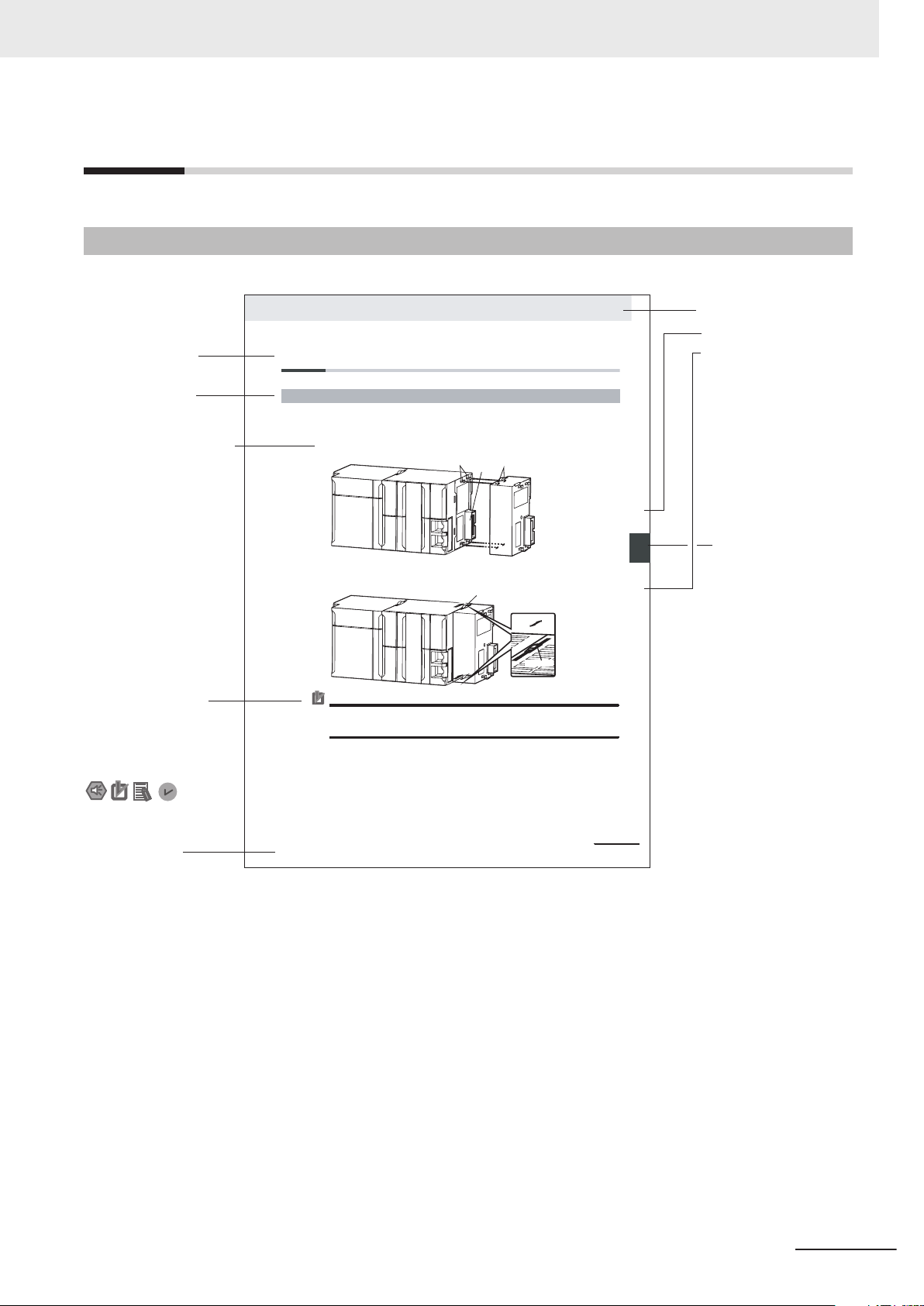
Level 1 heading
Level 2 heading
Level 3 heading
Level 2 heading
A step in a procedure
Manual name
Special information
Level 3 heading
Page tab
Gives the current
headings.
Indicates a procedure.
Icons indicate
precautions, additional
information, or reference
information.
Gives the number
of the main section.
This illustration is provided only as a sample. It may not literally appear in this manual.
The sliders on the tops and bottoms of the Power Supply Unit, C
PU Unit, I/O Units, Special I/O
Units, and CPU Bus Units must be completely locked (until they click into place) after connecting
the adjacent Unit connectors.
Page Structure
The following page structure is used in this manual.
Manual Structure
NJ/NX-series CPU Unit Built-in EtherNet/IP Port User’s Manual (W506)
5
Page 8

Manual Structure
Special Information
Special information in this manual is classified as follows:
Precautions for Safe Use
Precautions on what to do and what not to do to ensure safe usage of the product.
Precautions for Correct Use
Precautions on what to do and what not to do to ensure proper operation and performance.
Additional Information
Additional information to read as required.
This information is provided to increase understanding or make operation easier.
Version Information
Information on dif
and for dif
ferent versions of the Sysmac Studio is given.
ferences in specifications and functionality for Controller with different unit versions
Precaution on Terminology
In this manual, "download" refers to transferring data from the Sysmac Studio to the physical Controller and "upload
For the Sysmac Studio, "synchronization
"synchronize" means to automatically compare the data for the Sysmac Studio on the computer with
the data in the physical Controller and transfer the data in the direction that is specified by the user.
" refers to transferring data from the physical Controller to the Sysmac Studio.
" is used to both "upload" and "download" data. Here,
6
NJ/NX-series CPU Unit Built-in EtherNet/IP Port User’s Manual (W506)
Page 9

Sections in this Manual
Determining
IP Addresses
System-defined Variables
Related to the Built-in EtherNet/IP Port
Sysmac Studio Settings
for the Built-in EtherNet/IP Port
Testing Communications
Tag Data Link Functions
CIP Message
Communications
Socket Service
1
2
3
4
5
7
8
9
1
2
3
4
5
6
7
8
7
Appendices
A
Index
I
Introduction
Installing Ethernet
Networks
6
FTP Client
Automatic Clock
Adjustment
SNMP Agent
Communications Performance and Communications Load
Troubleshooting
FTP Server
11
Modbus TCP Master
Function
10
12
13
14
15
16
10
11
12
13
14
16
9
A
15
I
Sections in this Manual
NJ/NX-series CPU Unit Built-in EtherNet/IP Port User’s Manual (W506)
7
Page 10

CONTENTS
CONTENTS
Introduction .............................................................................................................. 1
Intended Audience...........................................................................................................................................1
Applicable Products
Relevant Manuals..................................................................................................... 2
Manual Structure...................................................................................................... 5
Page Structure.................................................................................................................................................5
Special Information .......................................................................................................................................... 6
Precaution on Terminology ..............................................................................................................................6
Sections in this Manual ........................................................................................... 7
Terms and Conditions Agreement........................................................................ 15
Warranty, Limitations of Liability ....................................................................................................................15
Application Considerations ............................................................................................................................16
Disclaimers ....................................................................................................................................................16
.........................................................................................................................................1
Safety Precautions................................................................................................. 18
Precautions for Safe Use ...................................................................................... 19
Precautions for Correct Use ................................................................................. 20
Regulations and Standards .................................................................................. 21
Versions.................................................................................................................. 22
Checking Versions.........................................................................................................................................22
Unit Versions of CPU Units and Sysmac Studio Versions.............................................................................26
Unit Versions of CPU Units and Peripheral Tool Versions.............................................................................26
Related Manuals..................................................................................................... 27
Revision History..................................................................................................... 30
Section 1 Introduction
1-1 Introduction ............................................................................................................................1-2
1-1-1 EtherNet/IP Features
1-1-2 Features of Built-in EtherNet/IP Port on NJ/NX-series CPU Units..............................................1-2
1-2 System Configuration and Configuration Devices ............................................................. 1-5
1-2-1 Devices Required to Construct a Network ..................................................................................1-5
1-2-2 Support Software Required to Construct a Network ...................................................................1-6
1-3 Built-in EtherNet/IP Port ........................................................................................................ 1-8
1-3-1 Specifications ..............................................................................................................................1-8
1-3-2 Part Names and Functions........................................................................................................1-12
1-4 Introduction to Communications Services........................................................................1-19
1-4-1 CIP (Common Industrial Protocol) Communications Services..................................................1-19
1-4-2 IP Routing .................................................................................................................................1-21
1-4-3 Packet Filter ..............................................................................................................................1-22
1-4-4 BOOTP Client ...........................................................................................................................1-23
1-4-5 FTP Server................................................................................................................................1-23
..................................................................................................................1-2
8
NJ/NX-series CPU Unit Built-in EtherNet/IP Port User’s Manual (W506)
Page 11

1-4-6 FTP Client .................................................................................................................................1-24
1-4-7 Automatic Clock Adjustment
1-4-8 Socket Service ..........................................................................................................................1-25
1-4-9 Specifying Host Names.............................................................................................................1-26
1-4-10 SNMP Agent .............................................................................................................................1-26
1-4-11 TCP/UDP Message Service......................................................................................................1-27
.....................................................................................................1-24
1-5 EtherNet/IP Communications Procedures.........................................................................1-28
Section 2 Installing Ethernet Networks
2-1 Selecting the Network Devices.............................................................................................2-2
2-1-1 Recommended Network Devices
2-1-2 Ethernet Switch Types ................................................................................................................2-3
2-1-3 Ethernet Switch Functions ..........................................................................................................2-3
2-1-4 Precautions for Ethernet Switch Selection ..................................................................................2-4
2-2 Network Installation...............................................................................................................2-7
2-2-1 Basic Installation Precautions .....................................................................................................2-7
2-2-2 Recommended Network Devices................................................................................................2-7
2-2-3 Precautions When Laying Twisted-pair Cable ............................................................................2-7
2-2-4 Precautions When Installing and Connecting Ethernet Switches .............................................2-11
2-3 Connecting to the Network .................................................................................................2-13
2-3-1 Ethernet Connectors .................................................................................................................2-13
2-3-2 Connecting the Cable................................................................................................................2-13
................................................................................................2-2
CONTENTS
Section 3 System-defined Variables Related to the Built-in Ether-
Net/IP Port
3-1 System-defined Variables Related to the Built-in EtherNet/IP Port...................................3-2
3-2 System-defined V
ariables .....................................................................................................3-3
3-3 Specifications for Individual System-defined Variables ..................................................3-36
Section 4 Determining IP Addresses
4-1 IP Addresses ..........................................................................................................................4-2
4-1-1 IP Address Configuration ............................................................................................................4-2
4-1-2 Allocating IP Addresses ..............................................................................................................4-2
4-1-3 Subnet Mask ...............................................................................................................................4-2
4-1-4 CIDR ...........................................................................................................................................4-3
4-2 Built-in EtherNet/IP Port IP Address Settings ..................................................................... 4-5
4-2-1 Determining IP Addresses ..........................................................................................................4-5
4-2-2 Setting IP Addresses...................................................................................................................4-5
4-2-3 Online Connection.......................................................................................................................4-7
4-2-4 Checking the Current IP Address..............................................................................................4-10
4-3 Private and Global Addresses ............................................................................................4-12
4-3-1 Private and Global Addresses...................................................................................................4-12
4-3-2 Using a Private Address for the Built-in EtherNet/IP Port .........................................................4-13
4-3-3 Using a Global Address for the Built-in EtherNet/IP Port ..........................................................4-14
Section 5 Sysmac Studio Settings for the Built-in EtherNet/IP Port
5-1 TCP/IP Settings Display ........................................................................................................5-2
5-2 LINK Settings
NJ/NX-series CPU Unit Built-in EtherNet/IP Port User’s Manual (W506)
Display............................................................................................................5-8
9
Page 12

CONTENTS
5-3 FTP Settings Display ............................................................................................................5-9
5-4 NTP Settings
Display...........................................................................................................5-10
5-5 SNMP Settings Display........................................................................................................5-12
5-6 SNMP Trap Settings Display...............................................................................................5-14
Section 6 Testing Communications
6-1 Testing Communications ......................................................................................................6-2
6-1-1 PING Command
6-1-2 Using the PING Command..........................................................................................................6-2
6-1-3 Host Computer Operation ...........................................................................................................6-2
..........................................................................................................................6-2
Section 7 Tag Data Link Functions
7-1 Introduction to Tag Data Links .............................................................................................7-2
7-1-1 T
7-1-2 Data Link Data Areas ..................................................................................................................7-3
7-1-3 Tag Data Link Functions and Specifications ...............................................................................7-6
7-1-4 Overview of Operation ................................................................................................................7-7
7-1-5 Starting and Stopping Tag Data Links.........................................................................................7-9
7-1-6 Controller Status .......................................................................................................................7-10
7-1-7 Concurrency of Tag Data Link Data ..........................................................................................7-12
7-2 Setting Tag Data Links ........................................................................................................7-19
7-2-1 Starting the Network Configurator.............................................................................................7-19
7-2-2 Tag Data Link Setting Procedure ..............................................................................................7-21
7-2-3 Registering Devices ..................................................................................................................7-21
7-2-4 Creating Tags and Tag Sets ......................................................................................................7-23
7-2-5 Connection Settings ..................................................................................................................7-36
7-2-6 Creating Connections Using the Wizard ...................................................................................7-46
7-2-7 Creating Connections by Dragging and Dropping Devices.......................................................7-49
7-2-8 Connecting the Network Configurator to the Network...............................................................7-52
7-2-9 Downloading Tag Data Link Parameters...................................................................................7-58
7-2-10 Uploading Tag Data Link Parameters .......................................................................................7-61
7-2-11 Verifying Tag Data Link Parameters ..........................................................................................7-64
7-2-12 Starting and Stopping Tag Data Links.......................................................................................7-68
7-2-13 Clearing the Device Parameters ...............................................................................................7-71
7-2-14 Saving the Network Configuration File......................................................................................7-73
7-2-15 Reading a Network Configuration File ......................................................................................7-74
7-2-16 Checking Connections ..............................................................................................................7-76
7-2-17 Changing Devices .....................................................................................................................7-77
7-2-18 Displaying Device Status ..........................................................................................................7-78
7-3 Ladder Programming for Tag Data Links ..........................................................................7-80
7-3-1 Ladder Programming for Tag Data Links ..................................................................................7-80
7-3-2 Status Flags Related to Tag Data Links....................................................................................7-84
7-4 Tag Data Links with Other Models .....................................................................................7-86
ag Data Links ............................................................................................................................7-2
Section 8 CIP Message Communications
8-1 Overview of the CIP Message Communications Service ................................................... 8-3
8-1-1 Overview of the CIP Message Communications Service............................................................8-3
8-1-2 Message Communications Service Specifications......................................................................8-3
8-2 CIP Message Communications Client Function .................................................................8-4
8-2-1 Overview .....................................................................................................................................8-4
8-2-2 CIP Communications Instructions ...............................................................................................8-4
8-2-3 Using CIP Communications Instructions.....................................................................................8-5
10
NJ/NX-series CPU Unit Built-in EtherNet/IP Port User’s Manual (W506)
Page 13

CONTENTS
8-2-4 Route Path ..................................................................................................................................8-6
8-2-5 Request Path (IOI)
8-2-6 Service Data and Response Data.............................................................................................8-20
8-2-7 Sample Programming for CIP Connectionless (UCMM) Message Communications................8-22
8-2-8 Sample Programming for CIP Connection (Class 3) Message Communications .....................8-27
8-2-9 Operation Timing.......................................................................................................................8-34
8-2-10 Response Codes.......................................................................................................................8-35
8-3 CIP Communication Server Function ................................................................................8-39
8-3-1 CIP Message Structure for Accessing CIP Objects ..................................................................8-39
8-3-2 CIP Message Structure for Accessing Variables.......................................................................8-40
8-4 Specifying Request Path.....................................................................................................8-41
8-4-1 Examples of CIP Object Specifications.....................................................................................8-41
8-4-2 Examples of Variable Specifications .........................................................................................8-42
8-4-3 Logical Segment .......................................................................................................................8-42
8-4-4 Data Segment ...........................................................................................................................8-42
8-4-5 Specifying Variable Names in Request Paths...........................................................................8-43
8-5 CIP Object Services .............................................................................................................8-47
8-5-1 CIP Objects Sent to the Built-in EtherNet/IP Port .....................................................................8-47
8-5-2 Identity Object (Class ID: 01 hex) .............................................................................................8-47
8-5-3 NX Configuration Object (Class ID: 74 hex)..............................................................................8-50
8-5-4 TCP/IP Interface Object (Class ID: F5 hex) ..............................................................................8-72
8-5-5 Ethernet Link Object (Class ID: F6 hex)....................................................................................8-75
8-5-6 Controller Object (Class ID: C4 hex).........................................................................................8-81
8-6 Read and Write Services for Variables ..............................................................................8-83
8-6-1 Read Service for Variables........................................................................................................8-83
8-6-2 Write Service for Variables ........................................................................................................8-84
8-7 Variable Data Types .............................................................................................................8-87
8-7-1 Data Type Codes ......................................................................................................................8-87
8-7-2 Common Format .......................................................................................................................8-87
8-7-3 Elementary Data Types.............................................................................................................8-88
8-7-4 Derived Data Types...................................................................................................................8-89
....................................................................................................................8-16
Section 9 Socket Service
9-1 Basic Knowledge on Socket Communications...................................................................9-2
9-1-1 Sockets
9-1-2 Port Numbers for Socket Services ..............................................................................................9-2
9-2 Basic Knowledge on Protocols ............................................................................................9-3
9-2-1 Differences between TCP and UDP............................................................................................9-3
9-2-2 Fragmenting of Send Data ..........................................................................................................9-4
9-2-3 Data Receive Processing............................................................................................................9-6
9-2-4 Broadcasting ...............................................................................................................................9-9
9-3 Overview of Built-in EtherNet/IP Port Socket Services .................................................... 9-10
9-3-1 Overview ...................................................................................................................................9-10
9-3-2 Procedure..................................................................................................................................9-10
9-4 Settings Required for the Socket Services .......................................................................9-11
9-5 Socket Service Instructions................................................................................................9-12
9-6 Details on Using the Socket Services................................................................................9-13
9-6-1 Using the Socket Services ........................................................................................................9-13
9-6-2 Procedure to Use Socket Services ...........................................................................................9-13
9-6-3 Timing Chart for Output Variables Used in Communications....................................................9-15
9-6-4 UDP Sample Programming.......................................................................................................9-16
9-6-5 TCP Sample Programming .......................................................................................................9-22
9-7 Precautions in Using Socket Services...............................................................................9-29
9-7-1 Precautions for UDP and TCP Socket Services .......................................................................9-29
9-7-2 Precautions for UDP Socket Services.......................................................................................9-29
9-7-3 Precautions for TCP Socket Services .......................................................................................9-29
.......................................................................................................................................9-2
NJ/NX-series CPU Unit Built-in EtherNet/IP Port User’s Manual (W506)
11
Page 14

CONTENTS
9-8 TCP/UDP Message Service .................................................................................................9-31
9-8-1 Outline of TCP/UDP Message Service
9-8-2 Specifications of TCP/UDP Message Service...........................................................................9-31
9-8-3 Settings Required for TCP/UDP Message Service ...................................................................9-31
9-8-4 Command Format Specifications ..............................................................................................9-31
.....................................................................................9-31
Section 10 Modbus TCP Master Function
10-1 Overview of Modbus TCP Master Function.......................................................................10-2
10-2 Modbus TCP Master Function Details
10-2-1 Modbus TCP Instruction Type...................................................................................................10-3
10-2-2 Modbus TCP Instruction Function.............................................................................................10-3
...............................................................................10-3
10-3 Modbus TCP Master Function Procedure .........................................................................10-4
Section 11 FTP Server
11-1 Overview and Specifications .............................................................................................. 11-2
11-1-1
11-1-2 Specifications ............................................................................................................................ 11-2
11-2 FTP Server Function Details ............................................................................................... 11-4
11-2-1 Supported Files ......................................................................................................................... 11-4
11-2-2 Connecting to the FTP Server................................................................................................... 11-4
11-3 Using the FTP Server Function ..........................................................................................11-7
11-3-1 Procedure.................................................................................................................................. 11-7
11-3-2 List of Settings Required for the FTP Server Function.............................................................. 11-7
11-4 FTP Server Application Example........................................................................................ 11-9
11-5 Using FTP Commands....................................................................................................... 11-11
11-5-1 Table of Commands ................................................................................................................ 11-11
11-5-2 Using the Commands.............................................................................................................. 11-11
11-6 Using SD Memory Card Operations ................................................................................. 11-18
11-6-1 SD Memory Card Types.......................................................................................................... 11-18
11-6-2 File Types................................................................................................................................ 11-19
11-6-3 Initializing SD Memory Cards..................................................................................................11-20
11-6-4 Format of Variable Data .......................................................................................................... 11-20
11-7 Application Example from a Host Computer................................................................... 11-21
Overview ...................................................................................................................................11-2
Section 12 FTP Client
12-1 Using the FTP Client to Transfer Files...............................................................................12-2
12-1-1 Transferring Files ......................................................................................................................12-2
12-1-2 Connectable FTP Servers.........................................................................................................12-2
12-1-3 File Transfer Options.................................................................................................................12-3
12-1-4 Other Functions.........................................................................................................................12-4
12-2 FTP Client Communications Instructions .........................................................................12-5
12-2-1 Functions of the FTP Client Communications Instructions .......................................................12-5
12-2-2 Restrictions on the FTP Client Communications Instructions ...................................................12-8
12-3 FTP Client Application Example.........................................................................................12-9
Section 13 Automatic Clock Adjustment
13-1 Automatic Clock Adjustment..............................................................................................13-2
13-1-1 Overview
12
...................................................................................................................................13-2
NJ/NX-series CPU Unit Built-in EtherNet/IP Port User’s Manual (W506)
Page 15

CONTENTS
13-1-2 Specifications ............................................................................................................................13-2
13-2 Procedure to Use the Automatic Clock Adjustment Function
13-2-1 Procedure..................................................................................................................................13-4
13-2-2 Settings Required for Automatic Clock Adjustment ..................................................................13-4
........................................13-4
Section 14 SNMP Agent
14-1 SNMP Agent .........................................................................................................................14-2
14-1-1 Overview
14-1-2 Specifications ............................................................................................................................14-3
14-1-3 SNMP Messages ......................................................................................................................14-3
14-1-4 MIB Specifications.....................................................................................................................14-4
...................................................................................................................................14-2
14-2 Procedure to Use the SNMP Agent ..................................................................................14-21
14-2-1 Procedures..............................................................................................................................14-21
14-2-2 Settings Required for the SNMP Agent...................................................................................14-21
Section 15 Communications Performance and Communications
Load
15-1 Communications System .................................................................................................... 15-2
15-1-1 T
15-1-2 Calculating the Number of Connections....................................................................................15-4
15-1-3 Packet Interval (RPI) Accuracy .................................................................................................15-5
ag Data Link Communications Method ...................................................................................15-2
15-2 Adjusting the Communications Load ................................................................................15-7
15-2-1 Checking Bandwidth Usage for Tag Data Links........................................................................15-8
15-2-2 Tag Data Link Bandwidth Usage and RPI.................................................................................15-9
15-2-3 Adjusting Device Bandwidth Usage ........................................................................................15-10
15-2-4 Changing the RPI....................................................................................................................15-11
15-2-5 RPI Setting Examples .............................................................................................................15-16
15-3 I/O Response Time in Tag Data Links .............................................................................. 15-22
15-3-1 Timing of Data Transmissions.................................................................................................15-22
15-3-2 Built-in EtherNet/IP Port Data Processing Time......................................................................15-23
15-3-3 Relationship between Task Periods and Packet Intervals (RPIs) ...........................................15-25
15-3-4 Maximum Tag Data Link I/O Response Time..........................................................................15-26
15-4 Message Service Transmission Delay .............................................................................15-29
Section 16 Troubleshooting
16-1 Overview of Troubleshooting .............................................................................................16-2
16-2 Checking Status with the Network Configurator ..............................................................16-3
16-2-1 The Network Configurator's Device Monitor Function...............................................................16-3
16-2-2 Connection Status Codes and Troubleshooting...................................................................... 16-11
Appendices
A-1 Functional Comparison
Other Series........................................................................................................................... A-2
A-2 Use the Sysmac Studio to Set the Tag Data Links (EtherNet/IP Connections)............... A-3
A-2-1 Overview of the Tag Data Links (EtherNet/IP Connections) Settings with the Sysmac Studio.. A-3
A-2-2 Procedure to Make the EtherNet/IP Connection Settings with the Sysmac Studio.................... A-4
A-2-3 EtherNet/IP Connection Settings ............................................................................................... A-5
A-2-4 Making the EtherNet/IP Connection Settings with the Sysmac Studio ...................................... A-9
A-2-5 Checking Communications Status with the Sysmac Studio and Troubleshooting ................... A-29
NJ/NX-series CPU Unit Built-in EtherNet/IP Port User’s Manual (W506)
of EtherNet/IP Ports on NJ/NX-series CPU Units and
13
Page 16

CONTENTS
A-3 EDS File Management
A-4 Precautions for Using the Network Configurator on Windows XP, Windows Vis-
A-5 Variable Memory Allocation Methods ............................................................................... A-46
A-6 Precautions When Accessing External Outputs in CPU Units....................................... A-59
A-7 TCP State Transitions......................................................................................................... A-60
A-8 Example of NX Unit Setting Using NX Configuration Object Service ............................ A-62
A-9 Version Information ............................................................................................................ A-64
A-2-6 Troubleshooting........................................................................................................................ A-34
........................................................................................................ A-39
A-3-1 Installing EDS Files .................................................................................................................. A-39
A-3-2 Creating EDS Files................................................................................................................... A-40
A-3-3 Deleting EDS Files ................................................................................................................... A-40
A-3-4 Saving EDS Files ..................................................................................................................... A-41
A-3-5 Searching EDS Files ................................................................................................................ A-41
A-3-6 Displaying EDS File Properties ................................................................................................ A-42
A-3-7 Creating EDS Index Files......................................................................................................... A-42
ta, or Windows 7 or Higher ................................................................................................ A-43
A-4-1 Changing Windows Firewall Settings....................................................................................... A-43
A-5-1 Variable Memory Allocation Rules............................................................................................ A-46
A-5-2 Important Case Examples........................................................................................................ A-55
A-8-1 Changing the Unit Operation Settings for Singe NX Unit......................................................... A-62
A-8-2 Changing the Unit Operation Settings for Multiple NX Units.................................................... A-63
A-8-3 Initializing the Unit Operation Settings for Singe NX Unit ........................................................ A-63
Index
14
NJ/NX-series CPU Unit Built-in EtherNet/IP Port User’s Manual (W506)
Page 17

Terms and Conditions Agreement
Terms and Conditions Agreement
Warranty, Limitations of Liability
Warranties
Exclusive Warranty
Omron’s exclusive warranty is that the Products will be free from defects in materials and workmanship for a period of twelve months from the date of sale by Omron (or such other period expressed in writing by Omron). Omron disclaims all other warranties, express or implied.
Limitations
OMRON MAKES NO WARRANTY OR REPRESENTATION, EXPRESS OR IMPLIED, ABOUT
NON-INFRINGEMENT, MERCHANTABILITY OR FITNESS FOR A PARTICULAR PURPOSE OF
THE PRODUCTS. BUYER ACKNOWLEDGES THAT IT ALONE HAS DETERMINED THAT THE
PRODUCTS WILL SUITABLY MEET THE REQUIREMENTS OF THEIR INTENDED USE.
Omron further disclaims all warranties and responsibility of any type for claims or expenses based
on infringement by the Products or otherwise of any intellectual property right.
Buyer Remedy
Omron’s sole obligation hereunder shall be, at Omron’s election, to (i) replace (in the form originally
shipped with Buyer responsible for labor charges for removal or replacement thereof) the non-complying Product, (ii) repair the non-complying Product, or (iii) repay or credit Buyer an amount equal
to the purchase price of the non-complying Product; provided that in no event shall Omron be responsible for warranty, repair, indemnity or any other claims or expenses regarding the Products
unless Omron’s analysis confirms that the Products were properly handled, stored, installed and
maintained and not subject to contamination, abuse, misuse or inappropriate modification. Return
of any Products by Buyer must be approved in writing by Omron before shipment. Omron Companies shall not be liable for the suitability or unsuitability or the results from the use of Products in
combination with any electrical or electronic components, circuits, system assemblies or any other
materials or substances or environments. Any advice, recommendations or information given orally
or in writing, are not to be construed as an amendment or addition to the above warranty.
See http://www.omron.com/global/ or contact your Omron representative for published information.
Limitation on Liability; Etc
OMRON COMPANIES SHALL NOT BE LIABLE FOR SPECIAL, INDIRECT, INCIDENTAL, OR CONSEQUENTIAL DAMAGES, LOSS OF PROFITS OR PRODUCTION OR COMMERCIAL LOSS IN ANY
NJ/NX-series CPU Unit Built-in EtherNet/IP Port User’s Manual (W506)
15
Page 18

Terms and Conditions Agreement
WAY CONNECTED WITH THE PRODUCTS, WHETHER SUCH CLAIM IS BASED IN CONTRACT,
WARRANTY
Further, in no event shall liability of Omron Companies exceed the individual price of the Product on
which liability is asserted.
, NEGLIGENCE OR STRICT LIABILITY.
Application Considerations
Suitability of Use
Omron Companies shall not be responsible for conformity with any standards, codes or regulations
which apply to the combination of the Product in the Buyer’
er’s request, Omron will provide applicable third party certification documents identifying ratings and
limitations of use which apply to the Product. This information by itself is not sufficient for a complete
determination of the suitability of the Product in combination with the end product, machine, system, or
other application or use. Buyer shall be solely responsible for determining appropriateness of the particular Product with respect to Buyer’s application, product or system. Buyer shall take application responsibility in all cases.
s application or use of the Product. At Buy-
NEVER USE THE PRODUCT FOR AN APPLICATION INVOLVING SERIOUS RISK TO LIFE OR
PROPERTY OR IN LARGE QUANTITIES WITHOUT ENSURING THAT THE SYSTEM AS A WHOLE
HAS BEEN DESIGNED TO ADDRESS THE RISKS, AND THAT THE OMRON PRODUCT(S) IS
PROPERLY RATED AND INSTALLED FOR THE INTENDED USE WITHIN THE OVERALL EQUIPMENT OR SYSTEM.
Programmable Products
Omron Companies shall not be responsible for the user’s programming of a programmable Product, or
any consequence thereof.
Disclaimers
Performance Data
Data presented in Omron Company websites, catalogs and other materials is provided as a guide for
the user in determining suitability and does not constitute a warranty. It may represent the result of
Omron’
formance is subject to the Omron’s Warranty and Limitations of Liability.
s test conditions, and the user must correlate it to actual application requirements. Actual per-
16
Change in Specifications
Product specifications and accessories may be changed at any time based on improvements and other reasons. It is our practice to change part numbers when published ratings or features are changed,
or when significant construction changes are made. However, some specifications of the Product may
NJ/NX-series CPU Unit Built-in EtherNet/IP Port User’s Manual (W506)
Page 19

Terms and Conditions Agreement
be changed without any notice. When in doubt, special part numbers may be assigned to fix or establish key specifications for your application. Please consult with your Omron’s representative at any
time to confirm actual specifications of purchased Product.
Errors and Omissions
Information presented by Omron Companies has been checked and is believed to be accurate; however, no responsibility is assumed for clerical, typographical or proofreading errors or omissions.
NJ/NX-series CPU Unit Built-in EtherNet/IP Port User’s Manual (W506)
17
Page 20

Safety Precautions
Safety Precautions
Refer to the following manuals for safety precautions.
• NX-series CPU Unit Hardware User's Manual (Cat. No. W535)
• NX-series NX102 CPU Unit Hardware User's Manual (Cat. No. W593)
• NX-series NX1P2 CPU Unit Hardware User's Manual (Cat. No. W578)
• NJ-series CPU Unit Hardware User’s Manual (Cat No. W500)
18
NJ/NX-series CPU Unit Built-in EtherNet/IP Port User’s Manual (W506)
Page 21

Precautions for Safe Use
Refer to the following manuals for precautions for safe use.
• NX-series CPU Unit Hardware User's Manual (Cat. No. W535)
• NX-series NX102 CPU Unit Hardware User's Manual (Cat. No. W593)
• NX-series NX1P2 CPU Unit Hardware User's Manual (Cat. No. W578)
• NJ-series CPU Unit Hardware User’s Manual (Cat No. W500)
Precautions for Safe Use
NJ/NX-series CPU Unit Built-in EtherNet/IP Port User’s Manual (W506)
19
Page 22

Precautions for Correct Use
Precautions for Correct Use
Refer to the following manuals for precautions for correct use.
• NX-series CPU Unit Hardware User's Manual (Cat. No. W535)
• NX-series NX102 CPU Unit Hardware User's Manual (Cat. No. W593)
• NX-series NX1P2 CPU Unit Hardware User's Manual (Cat. No. W578)
• NJ-series CPU Unit Hardware User’s Manual (Cat No. W500)
20
NJ/NX-series CPU Unit Built-in EtherNet/IP Port User’s Manual (W506)
Page 23

Regulations and Standards
Refer to the following manuals for regulations and standards.
• NX-series CPU Unit Hardware User's Manual (Cat. No. W535)
• NX-series NX102 CPU Unit Hardware User's Manual (Cat. No. W593)
• NX-series NX1P2 CPU Unit Hardware User's Manual (Cat. No. W578)
• NJ-series CPU Unit Hardware User’s Manual (Cat No. W500)
Regulations and Standards
NJ/NX-series CPU Unit Built-in EtherNet/IP Port User’s Manual (W506)
21
Page 24
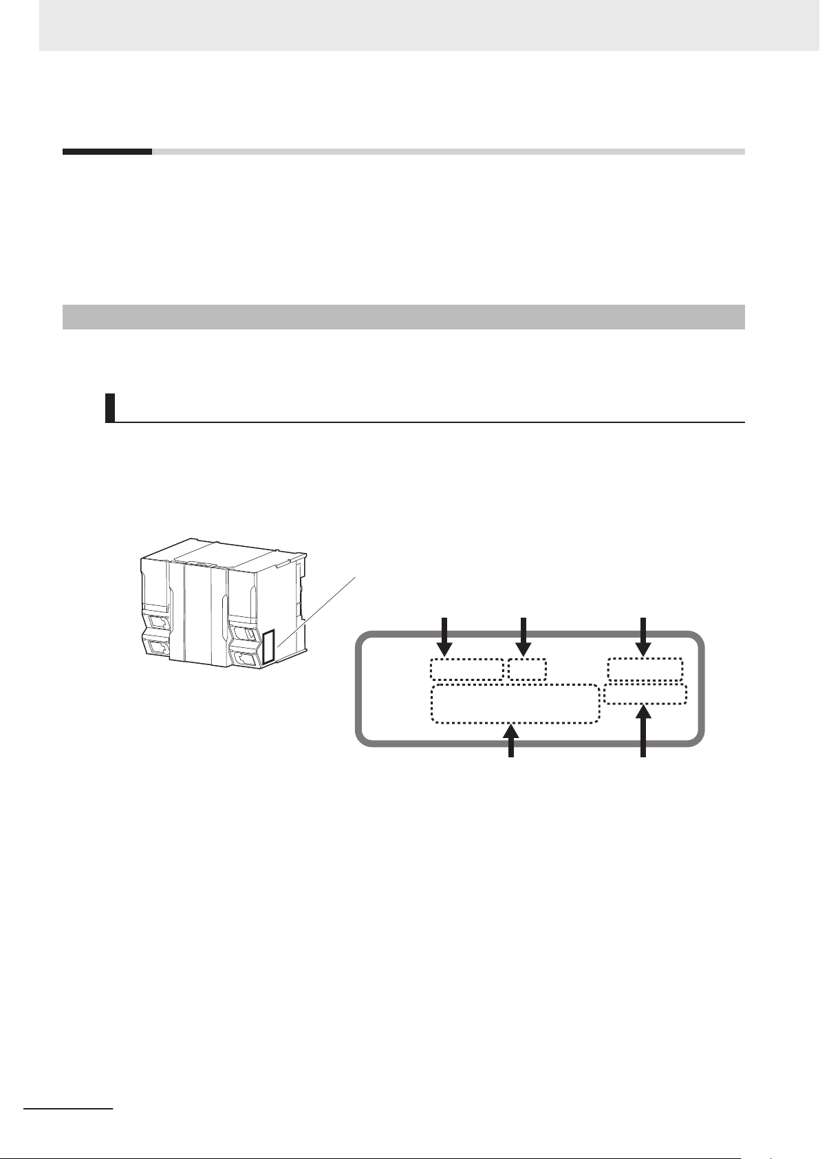
ID information indication
Lot number Serial number Unit version
MAC address Hardware revision
LOT No. DDMYY£ xxxx Ver.1.
££
PORT1 : ££££££££££££ HW Rev. £
PORT2 : ££££££££££££
Versions
Versions
Hardware revisions and unit versions are used to manage the hardware and software in NJ/NX-series
Units and EtherCAT slaves. The hardware revision or unit version is updated each time there is a
change in hardware or software specifications. Even when two Units or EtherCAT slaves have the
same model number, they will have functional or performance differences if they have different hardware revisions or unit versions.
Checking Versions
You can check versions on the ID information indications or with the Sysmac Studio.
Checking Unit Versions on ID Information Indications
The unit version is given on the ID information indication on the side of the product.
For NX701
The ID information on an NX-series NX701-££££ CPU Unit is shown below.
Note The hardware revision is not displayed for the Unit whose hardware revision is blank.
For NX102
The ID information on an NX-series NX102-££££ CPU Unit is shown below
.
22
NJ/NX-series CPU Unit Built-in EtherNet/IP Port User’s Manual (W506)
Page 25
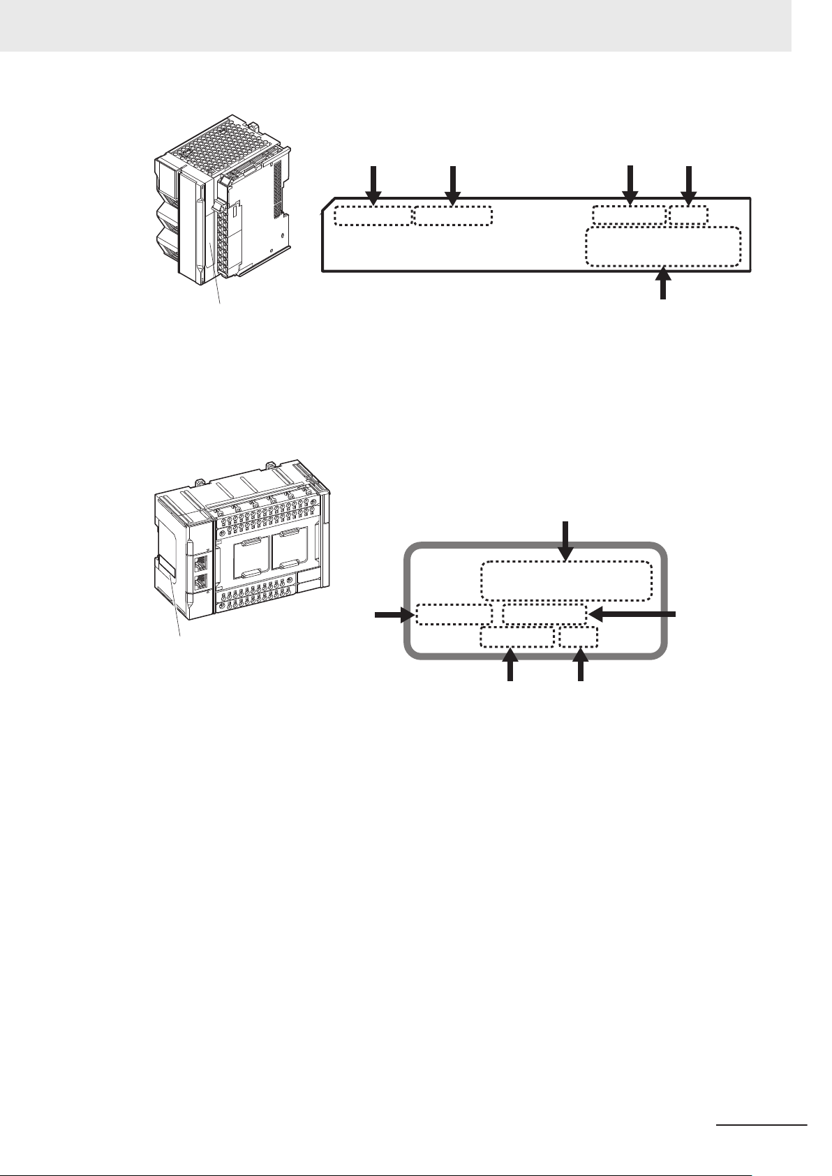
ID Information Indication
Unit version Hardware revision
Lot number
Serial number
MAC address
LOT No. DDMYY£ xxxx
PORT1
££££££££££££
PORT2
££££££££££££
Ver.£.££ HW Rev.£
Note The hardware revision is not displayed for the Unit whose hardware revision is blank.
PORT1 : ££££££££££££
PORT2
: ££££££££££££
Ver.1.££ HW Rev. £
LOT No. DDMYY£ xxxx
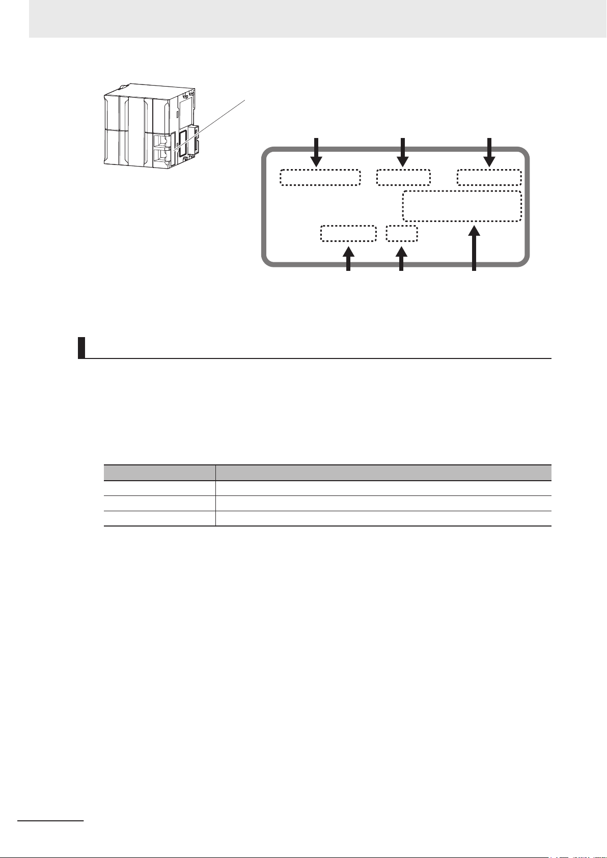
ID information indication
Lot number
Serial number
Unit version
MAC address
Hardware
revision
For NX1P2
The ID information on an NX-series NX1P2-£££££££
CPU Unit is shown below
Versions
.
NJ/NX-series CPU Unit Built-in EtherNet/IP Port User’s Manual (W506)
Note The hardware revision is not displayed for the Unit that the hardware revision is in blank.
For NJ-series
The ID information on an NJ-series NJ501-££££ CPU Unit is shown below.
23
Page 26
ID information indication
Unit model
Lot number Serial number MAC address
Unit version Hardware revision
NJ501-££££
Ver.1.
££
PORT1 MAC ADDRESS:
££££££££££££
PORT2 MAC ADDRESS:
££££££££££££
Lot No. DDMYY
£
xxxx
HW Rev.
£
Versions
Note The hardware revision is not displayed for the Unit that the hardware revision is in blank.
Checking Unit Versions with the Sysmac Studio
You can use the Sysmac Studio to check unit versions. The procedure is different for Units and for
EtherCAT slaves.
Checking the Unit V
You can use the Production Information while the Sysmac Studio is online to check the unit version
of a Unit. You can do this for the following Units.
Model Unit for which unit version can be checked
NX701-££££
NX102-££££
NX1P2-££££
ersion of an NX-series CPU Unit
CPU Unit
CPU Unit and NX Unit on CPU Rack
CPU Unit, NX Unit on CPU Rack, and Option Boards
1 Right-click CPU Rack under Configurations and Setup - CPU/Expansion Racks in the Multi-
view Explorer and select Production Information.
The Production Information Dialog Box is displayed.
Checking the Unit Version of an NJ-series CPU Unit
You can use the Production Information while the Sysmac Studio is online to check the unit version
of a Unit. Y
Units. Y
ou can do this for the CPU Unit, CJ-series Special I/O Units, and CJ-series CPU Bus
ou cannot check the unit versions of CJ-series Basic I/O Units with the Sysmac Studio.
24
1 Double-click CPU Rack under Configurations and Setup - CPU/Expansion Racks
Multiview Explorer. Or, right-click CPU Rack under Configurations and Setup - CPU/
Expansion Racks in the Multiview Explorer and select Edit from the menu.
The Unit Editor is displayed.
2 Right-click any open space in the Unit Editor and select Production Information.
The Production Information Dialog Box is displayed.
NJ/NX-series CPU Unit Built-in EtherNet/IP Port User’s Manual (W506)
in the
Page 27
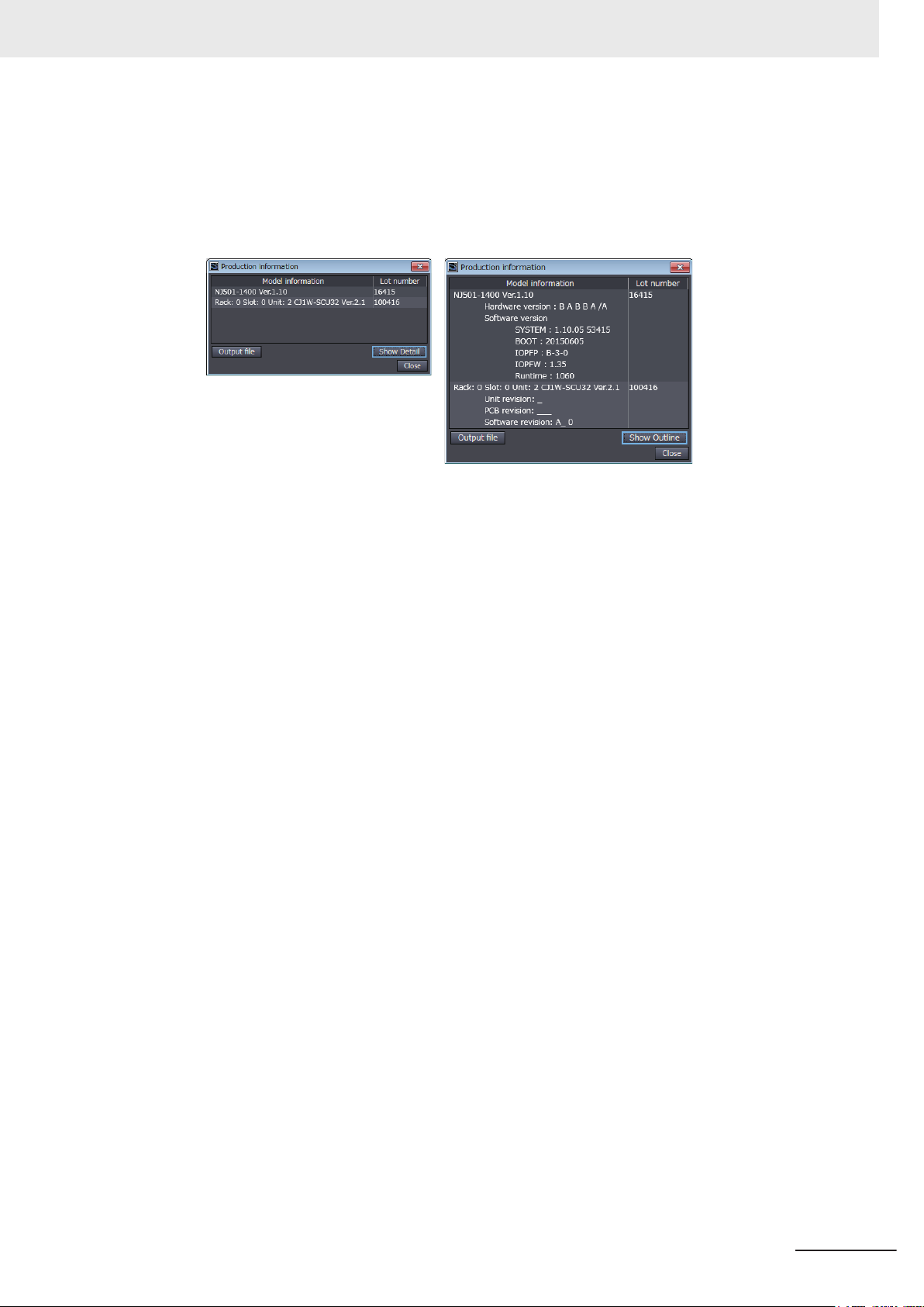
Changing Information Displayed in Production Information Dialog Box
Versions
1 Click the Show Detail or
Dialog Box.
The view will change between the production information details and outline.
Outline View Detail View
The information that is displayed is different for the Outline View and Detail View. The Detail
V
iew displays the unit version, hardware revision, and various versions. The Outline View dis-
plays only the unit version.
Note The hardware revision is separated by “/” and displayed on the right of the hardware version. The
hardware revision is not displayed for the Unit that the hardware revision is in blank.
Show Outline Button at the lower right of the Production Information
Checking the Unit V
You can use the Production Information while the Sysmac Studio is online to check the unit version
of an EtherCAT slave.
Use the following procedure to check the unit version.
1 Double-click EtherCAT
click EtherCAT under Configurations and Setup and select Edit from the menu.
The EtherCAT Tab Page is displayed.
ersion of an EtherCAT Slave
under Configurations and Setup in the Multiview Explorer. Or, right-
2 Right-click the master on the EtherCAT Tab Page and select Display Production Information.
The Production Information Dialog Box is displayed.
The unit version is displayed after “Rev.”
Changing Information Displayed in Production Information Dialog Box
1 Click the
Dialog Box.
The view will change between the production information details and outline.
Show Detail or Show Outline Button at the lower right of the Production Information
NJ/NX-series CPU Unit Built-in EtherNet/IP Port User’s Manual (W506)
25
Page 28

Versions
Outline View Detail View
Unit Versions of CPU Units and Sysmac Studio Versions
The functions that are supported depend on the unit version of the NJ/NX-series CPU Unit. The version of Sysmac Studio that supports the functions that were added for an upgrade is required to use
those functions.
Refer to the NJ/NX-series CPU Unit Software User’s Manual (Cat. No. W501) for the relationship between the unit versions of CPU Units and the Sysmac Studio versions, and for the functions that are
supported by each unit version.
Unit Versions of CPU Units and Peripheral Tool Versions
When you set tag data links for the built-in EtherNet/IP port on an NJ/NX-series CPU Unit, use the
versions of the Network Configurator and the Sysmac Studio that are given in the following table.
OK: Supported, ---: Not supported
CPU Unit Network Configurator for EtherNet/IP Sysmac Studio
Ver.
Model Version
NJ501 Ver.
1.00 to
1.02
NJ301 Ver.
1.01 to
1.02
NJ501
NJ301
NJ101
NX701
NX1P2 Ver.
NX102 Ver.
*1.
Ver.
1.03 or
higher
Ver.
1.10 or
later
1.13 or
later
1.30 or
later
Use an NX1P2-9B£££££ CPU Unit with Sysmac Studio version 1.30 or higher.
3.3x
or
lower
---
--- ---
--- --- ---
--- --- --- ---
--- --- --- --- ---
--- --- --- --- --- ---
Ver.
3.40
OK OK OK OK OK OK
Ver.3.
50 or
3.51
OK OK OK OK OK
Ver.
3.53
to
3.58
OK OK OK OK
Ver.
3.59
to
3.60
OK OK OK
Ver.
3.61
3.63
OK OK
to
3.64 or
higher
OK
Ver.
Ver.
1.09
lower
---
---
---
--- ---
--- --- ---
--- --- --- ---
Ver.
1.10
or
to
1.12
OK OK OK OK
OK OK OK OK
OK OK OK OK
Ver.
1.13
1.16
OK OK OK
to
Ver.
1.17
1.22
OK
to
higher
¡
OK
Ver.
1.23
or
*1
26
NJ/NX-series CPU Unit Built-in EtherNet/IP Port User’s Manual (W506)
Page 29

Related Manuals
The followings are the manuals related to this manual. Use these manuals for reference.
Manual name Cat. No. Model number Application Description
NX-series CPU Unit
Hardware User's Manual
NX-series
NX102 CPU Unit
Hardware
User
’
s Manual
NX-series
NX1P2 CPU Unit
Hardware
User
s Manual
’
NJ-series CPU Unit
Hardware User's Manual
NJ/NX-series CPU Unit
Software User
s Manual
’
W535
W593
W578
W500
W501
NX701-££££
NX102-££££
NX1P2-££££
NJ501-££££
NJ301-££££
NJ101-££££
NX701-££££
NX102-££££
NX1P2-££££
NJ501-££££
NJ301-££££
NJ101-££££
Learning the basic
specifications of the
NX701 CPU Units,
including introductory
information, designing, installation, and
maintenance.
Mainly hardware information is provided.
Learning the basic
specifications of the
NX102 CPU Units,
including introductory
information, designing, installation, and
maintenance.
Mainly hardware information is provided.
Learning the basic
specifications of the
NX1P2 CPU Units,
including introductory
information, designing, installation, and
maintenance.
Mainly hardware information is provided.
Learning the basic
specifications of the
NJ-series CPU Units,
including introductory
information, designing, installation, and
maintenance.
Mainly hardware information is provided.
Learning how to program and set up an
NJ/NX-series CPU
Unit.
Mainly software information is provided.
Related Manuals
An introduction to the entire NX701 system
is provided along with the following information on the CPU Unit.
• Features and system configuration
• Introduction
• Part names and functions
• General specifications
• Installation and wiring
• Maintenance and inspection
An introduction to the entire NX102 system
is provided along with the following information on the CPU Unit.
• Features and system configuration
• Introduction
• Part names and functions
• General specifications
• Installation and wiring
• Maintenance and inspection
An introduction to the entire NX1P2 system
is provided along with the following information on the CPU Unit.
• Features and system configuration
• Introduction
• Part names and functions
• General specifications
• Installation and wiring
• Maintenance and inspection
An introduction to the entire NJ-series system is provided along with the following information on the CPU Unit.
• Features and system configuration
• Introduction
• Part names and functions
• General specifications
• Installation and wiring
• Maintenance and inspection
The following information is provided on a
Controller built with an NJ/NX-series CPU
Unit.
• CPU Unit operation
• CPU Unit features
• Initial settings
• Programming based on IEC 61131-3
language specifications
NJ/NX-series CPU Unit Built-in EtherNet/IP Port User’s Manual (W506)
27
Page 30

Related Manuals
Manual name Cat. No. Model number Application Description
NX-series NX1P2 CPU Unit
Built-in I/O and Option Board
’
s Manual
User
NJ/NX-series Instructions
Reference Manual
NJ/NX-series CPU Unit
Motion Control User’
ual
NJ/NX-series
Motion Control Instructions
Reference Manual
NJ/NX-series
CPU Unit
Built-in EtherCA
User
’s Manual
NJ/NX-series
CPU Unit
Built-in EtherNet/IP™ Port
s Manual
User’
NJ/NX-series
CPU Unit
OPC UA
s Manual
’
User
NX-series
CPU Unit
FINS Function
s Manual
User’
NJ/NX-series
Database Connection CPU
Units
s Manual
User’
NJ-series
SECS/GEM CPU Units
’s Manual
User
NJ-series
Robot Integrated CPU Unit
s Manual
User’
s Man-
T® Port
W579
W502
W507
W508
W505
W506
W588
W596
W527
W528 NJ501-1340 Using the GEM Serv-
O037
NX1P2-££££
NX701-££££
NX102-££££
NX1P2-££££
NJ501-££££
NJ301-££££
NJ101-££££
NX701-££££
NX102-££££
NX1P2-££££
NJ501-££££
NJ301-££££
NJ101-££££
NX701-££££
NX102-££££
NX1P2-££££
NJ501-££££
NJ301-££££
NJ101-££££
NX701-££££
NX102-££££
NX1P2-££££
NJ501-££££
NJ301-££££
NJ101-££££
NX701-££££
NX102-££££
NX1P2-££££
NJ501-££££
NJ301-££££
NJ101-££££
NX102-££££
NJ501-1£00
NX701-££20
NX102-££££
NX701-££20
NX102-££20
NJ501-££20
NJ101-££20
NJ501-R£££
Learning about the
details of functions
only for an NX-series
NX1P2 CPU Unit and
an introduction of
functions for an
NJ/NX-series CPU
Unit.
Learning detailed
specifications on the
basic instructions of
an NJ/NX-series
CPU Unit.
Learning about motion control settings
and programming
concepts.
Learning about the
specifications of the
motion control instructions.
Using the built-in
EtherCA
NJ/NX-series CPU
Unit.
Using the built-in
EtherNet/IP port on
an NJ/NX-series
CPU Unit.
Using the OPC UA. Describes the OPC UA.
Using the FINS function of an NX-series
CPU Unit.
Using the database
connection service
with NJ/NX-series
Controllers.
ices with NJ-series
Controllers.
Using the NJ-series
Robot Integrated
CPU Unit.
T port on an
Of the functions for an NX1P2 CPU Unit,
the following information is provided.
• Built-in I/O
• Serial Communications Option Boards
• Analog I/O Option Boards
An introduction of following functions for an
NJ/NX-series CPU Unit is also provided.
• Motion control functions
• EtherNet/IP communications functions
• EtherCA
The instructions in the instruction set (IEC
131-3 specifications) are described.
61
The settings and operation of the CPU Unit
and programming concepts for motion control are described.
The motion control instructions are described.
Information on the built-in EtherCAT port is
provided.
This manual provides an introduction and
provides information on the configuration,
features, and setup.
Information on the built-in EtherNet/IP port
is provided.
Information is provided on the basic setup,
tag data links, and other features.
Describes the FINS function of an NX-series CPU Unit.
Describes the database connection service.
Provides information on the GEM Services.
Describes the settings and operation of the
CPU Unit and programming concepts for
OMRON robot control.
T communications functions
28
NJ/NX-series CPU Unit Built-in EtherNet/IP Port User’s Manual (W506)
Page 31

Manual name Cat. No. Model number Application Description
Sysmac Studio
Robot Integrated System
Building Function with Robot
Integrated CPU Unit Operation Manual
Sysmac Studio
Robot Integrated System
Building Function with IPC
Application Controller Operation Manual
Sysmac Studio
3D Simulation Function Operation Manual
NJ-series
NJ Robotics CPU Unit
s Manual
’
User
NJ/NY-series
NC Integrated Controller
s Manual
User’
NJ/NY-series
G code
Instructions Reference Manual
NJ/NX-series
Troubleshooting Manual
Sysmac Studio Version 1
Operation Manual
CNC Operator
Operation Manual
NX-series
Safety Control Unit
User's Manual
W595
W621
W618
W539
O030 NJ501-5300
O031 NJ501-5300
W503
W504 SYSMAC
O032 SYSMAC
Z930
SYSMAC-SE2£££
SYSMACSE200D-64
SYSMAC-SE2£££
SYSMACSE200D-64
SYSMAC-SE2
SYSMAC-SA4££
£-64
NJ501-4£££
NJ501-R£££
NY532-5400
NY532-5400
NX701-££££
NX102-££££
££££
NX1P2NJ501-££££
NJ301-££££
NJ101-££££
-SE2£££
TNC0
£££D
-R
NX-SL££££
NX-SI££££
NX-SO££££
Learning about the
operating procedures
and functions of the
Sysmac Studio to
configure Robot Integrated System using
Robot Integrated
CPU Unit.
Learning about the
operating procedures
and functions of the
Sysmac Studio to
configure Robot Integrated System using
IPC Application Controller
Learning about an
£££
outline of the 3D simulation function of the
Sysmac Studio and
how to use the function.
Controlling robots
with NJ-series CPU
Units.
Performing numerical
control with NJ/NYseries Controllers.
Learning about the
specifications of the
G code/M code instructions.
Learning about the
errors that may be
detected in an
NJ/NX-series Controller
Learning about the
operating procedures
and functions of the
Sysmac Studio.
Learning an introduction of the CNC Operator and how to
use it.
Learning how to use
NX-series Safety
Control Units.
Describes the operating procedures of the
Sysmac Studio for Robot Integrated CPU
Unit.
Describes the operating procedures of the
Sysmac Studio for IPC Application Controller.
.
Describes an outline, execution procedures, and operating procedures for the 3D
simulation function of the Sysmac Studio.
Describes the functionality to control robots.
Describes the functionality to perform the
numerical control.
The G code/M code instructions are described.
Concepts on managing errors that may be
detected in an NJ/NX-series Controller and
information on individual errors are described.
.
Describes the operating procedures of the
Sysmac Studio.
An introduction of the CNC Operator, installation procedures, basic operations,
connection operations, and operating procedures for main functions are described.
Describes the hardware, setup methods,
and functions of the NX-series Safety Control Units.
Related Manuals
NJ/NX-series CPU Unit Built-in EtherNet/IP Port User’s Manual (W506)
29
Page 32

W506-E1-24
Revision code
Cat. No.
Revision History
Revision History
A manual revision code appears as a suffix to the catalog number on the front and back covers of the
manual.
Revision
code
01 July 2011 Original production
02 March 2012
03 May 2012
04 August 2012
05 February 2013
06 April 2013
07 June 2013
08 December 2013
09 July 2014
10 January 2015
11 April 2015
12 October 2015
13 April 2016
Date Revised content
• Added information on the NJ301-££££.
• Added A-8 Accesing Variables with CIP Message Communications.
• Added information on the functions supported by unit version 1.01 of the
CPU Units.
• Corrected mistakes.
• Added information on the functions supported by unit version 1.02 of the
CPU Units.
• Corrected mistakes.
• Added information on the functions supported by unit version 1.03 of the
CPU Units.
• Corrected mistakes.
• Added information on the functions supported by unit version 1.04 of the
CPU Units.
• Corrected mistakes.
• Corrected mistakes.
• Added information on the functions supported by unit version 1.06 of the
CPU Units.
• Added information on the functions supported by unit version 1.08 of the
CPU Units.
• Corrected mistakes.
• Added information on the functions supported by unit version 1.09 of the
CPU Units.
• Corrected mistakes.
• Added information on the functions supported by unit version 1.10 of the
CPU Units.
• Corrected mistakes.
• Added information on the NX701-££££.
• Added information on the NJ101-££££.
• Corrected mistakes.
• Added information on the hardware revision.
• Corrected mistakes.
• Added information on the functions supported by unit version 1.11 of the
CPU Units.
• Corrected mistakes.
30
NJ/NX-series CPU Unit Built-in EtherNet/IP Port User’s Manual (W506)
Page 33

Revision History
Revision
code
14 July 2016
15 October 2016
16 April 2017
17 October 2017
18 January 2018
19 April 2018
20 July 2018
21 April 2019
22 July 2019
23 October 2019
24 August 2020
Date Revised content
• Added information on the functions supported by unit version 1.12 of the
CPU Units.
• Corrected mistakes.
• Added information on the NX1P2-££££££.
• Added information on the functions supported by unit version 1.13 of the
CPU Units.
• Corrected mistakes.
• Added information on the functions supported by unit version 1.14 of the
CPU Units.
• Corrected mistakes.
• Corrected mistakes.
• Added information on the functions supported by unit version 1.17 of the
CPU Units.
• Corrected mistakes.
• Added information on the NX102-££££.
• Added information on the functions supported by unit version 1.30 of the
CPU Units.
• Consolidated descriptions related to event codes and errors into the
NJ/NX-series Troubleshooting Manual.
• Corrected mistakes.
• Added information on the functions supported by unit version 1.31 of the
££££.
NX102-
• Added information on the functions supported by unit version 1.32 of
NX102-££££.
• Added information on the functions supported by unit version 1.21 of the
NX1P2-££££££, NJ501-1£00, NJ301-££££, and NJ101-££00.
• Corrected mistakes.
• Added information on the functions supported by unit version 1.21 of the
NX701-££££, NJ501-4£00, NJ501-4£10, NJ501-1340 and
NJ501-5300.
• Corrected mistakes.
• Added information on the NX1P2-9B££££.
• Corrected mistakes.
• Made changes accompanying the addition of NJ501-R£££.
• Corrected mistakes.
NJ/NX-series CPU Unit Built-in EtherNet/IP Port User’s Manual (W506)
31
Page 34

Revision History
32
NJ/NX-series CPU Unit Built-in EtherNet/IP Port User’s Manual (W506)
Page 35

Introduction
1-1 Introduction ....................................................................................................1-2
1-1-1 EtherNet/IP Features
1-1-2 Features of Built-in EtherNet/IP Port on NJ/NX-series CPU Units .................. 1-2
1-2 System Configuration and Configuration Devices .....................................1-5
1-2-1 Devices Required to Construct a Network ...................................................... 1-5
1-2-2 Support Software Required to Construct a Network ....................................... 1-6
1-3 Built-in EtherNet/IP Port ................................................................................1-8
1-3-1 Specifications .................................................................................................. 1-8
1-3-2 Part Names and Functions............................................................................ 1-12
1-4 Introduction to Communications Services................................................ 1-19
1-4-1 CIP (Common Industrial Protocol) Communications Services ...................... 1-19
1-4-2 IP Routing...................................................................................................... 1-21
1-4-3 Packet Filter .................................................................................................. 1-22
1-4-4 BOOTP Client................................................................................................ 1-23
1-4-5 FTP Server .................................................................................................... 1-23
1-4-6 FTP Client ..................................................................................................... 1-24
1-4-7 Automatic Clock Adjustment ......................................................................... 1-24
1-4-8 Socket Service .............................................................................................. 1-25
1-4-9 Specifying Host Names ................................................................................. 1-26
1-4-10 SNMP Agent.................................................................................................. 1-26
1-4-11 TCP/UDP Message Service .......................................................................... 1-27
1-5 EtherNet/IP Communications Procedures................................................. 1-28
1
....................................................................................... 1-2
1
NJ/NX-series CPU Unit Built-in EtherNet/IP Port User’s Manual (W506)
1-1
Page 36

EtherNet/IP System Configuration Example
Ethernet (LAN) port
100 m
max.
(1) Built-in EtherNet/IP
port on NJ/NX
-
series Controller
(2) Twisted-pair cable
(3) Ethernet switch
Sysmac Studio
(Support Software)
(1) Built-in EtherNet/IP
port on NJ/NXseries Controller
(1) Built-in EtherNet/IP
port on NJ/NXseries Controller
1 Introduction
1-1
1-1-1
Introduction
EtherNet/IP Features
EtherNet/IP is an industrial multi-vendor network that uses Ethernet.
The EtherNet/IP specifications are open standards managed by the ODVA (Open DeviceNet Vendor
Association), just like DeviceNet.
EtherNet/IP is not just a network between Controllers. It is also used as a field network. Because
EtherNet/IP uses standard Ethernet technology, various general-purpose Ethernet devices can be
used in the network.
1-1-2
High-speed, High-capacity Data Exchange through Tag Data Links
The EtherNet/IP protocol supports implicit communications, which allows cyclic communications
(called tag data links in this manual) with EtherNet/IP devices.
Tag Data Link (Cyclic Communications) Cycle Time
Tag data links (cyclic communications) operate at the cyclic period specified for each application,
regardless of the number of nodes. Data is exchanged over the network at the refresh cycle set for
each connection, so the communications refresh cycle will not increase even if the number of nodes is increased, i.e., the concurrency of the connection's data is maintained.
Because the refresh cycle can be set for each connection, each application can communicate at its
ideal refresh cycle. For example, interprocess interlocks can be transferred at high speed, while the
production commands and the status monitor information are transferred at low speed.
Features of Built-in EtherNet/IP Port on NJ/NX-series CPU Units
Tag Data Links
Cyclic communications between Controllers or between a Controller and other devices are possible
on an EtherNet/IP network.
High-speed data exchange can be performed through tag data links.
1-2
NJ/NX-series CPU Unit Built-in EtherNet/IP Port User’s Manual (W506)
Page 37

1 Introduction
CIP Message Communications
You can send CIP commands to devices on the EtherNet/IP network when required by executing
CIP communications instructions in a program.
As a result, it is possible to send and receive data with the devices on the EtherNet/IP network.
BOOTP Client
If the built-in EtherNet/IP port on an NJ/NX-series CPU Unit is set in the BOOTP settings, the
BOOTP client operates when the Controller power is turned ON, and the IP address is obtained
from the BOOTP server.
It is possible to set all of the IP addresses of multiple built-in EtherNet/IP ports at the same time.
1-1 Introduction
1
1-1-2 Features of Built-in EtherNet/IP Port on NJ/NX-series CPU Units
FTP Server for File T
An FTP server is built into the Controller. You can use it to read and write data within the Controller
as files from workstations and computers with FTP clients.
The FTP server enables the transfer of large amounts of data from a client without any additional
ladder programming.
FTP Client for File Transfers to and from Host Computers
An FTP client is built into the Controller, so you can read and write files on workstations and computers that have an FTP server from the Controller.
You can use the FTP client communications instructions to transfer one or more files between the
Controller and an FTP server.
NTP Client for Automatic Controller Clock Adjustment
The clocks built into Controllers connected to Ethernet can be automatically adjusted to the time of
the clock in the NTP server. If all of the clocks in the system are automatically adjusted to the same
time, time stamps can be used to analyze production histories.
*1. A separate NTP server is necessary to automatically adjust the Controller clocks.
Socket Services
Socket services can be used to send and receive data between general-purpose applications and
Controllers.
Through the communications services with sockets, you can send and receive data to and from remote nodes, i.e., between the host computer and Controllers or between Controllers.
You can execute socket communications instructions in order in a program to execute communications processes with the socket services.
There are two socket services, the UDP socket service and TCP socket service.
ransfers to and from Host Computers
DNS Client for Specifying Host Names
When you specify an NTP server, SNMP manager, or the destination of socket instructions or CIP
communications instructions, you can use the host name, as well as its IP address (DNS client or
hosts settings).
This will help identify the IP address automatically even after the IP addresses of relevant servers
are changed due to system revisions.
*1. A separate DNS server is necessary when you use host names with the DNS client.
*2. The DNS server is specified directly using its IP address.
NJ/NX-series CPU Unit Built-in EtherNet/IP Port User’s Manual (W506)
1-3
Page 38

1 Introduction
Network Management with an SNMP Manager
The SNMP agent passes internal status information from the built-in EtherNet/IP port to network
management software that uses an SNMP manager.
*1.
Complete Troubleshooting Functions
A variety of functions are provided to quickly identify and handle errors.
• Self-diagnosis at startup
• Event log that records the time of occurrence and other error details
Two EtherNet/IP Communications Ports as a Standard Feature, Equipped
with IP Routing Function (Only with the NX701 and NX102 CPU Units)
These CPU Units are equipped with two EtherNet/IP ports for EtherNet/IP communications as
standard.
This feature allows you to separate the information network from the control network. In addition,
the built-in EtherNet/IP ports support the IP routing function to send IP packets to devices on other
IP network segments.
*1. In order to use the function, you must appropriately set the IP router table and default gateway settings for
A separate SNMP manager is necessary for network management.
each device on the network according to your network configuration. For details on the settings, refer to
5-1 TCP/IP Settings Display on page 5-2.
CIP Safety on EtherNet/IP Compatible
Combined with the NX-SL5£££
Safety on EtherNet/IP communications in networks between Controllers and field networks. Safety
communications by CIP Safety is enabled with devices that support CIP Safety on EtherNet/IP and
other Safety CPU Units.
Additional Information
CIP (Common Industrial Protocol)
CIP is a shared industrial protocol for the OSI application layer. The CIP is used in networks
such as EtherNet/IP
Data can be routed easily between networks that are based on the CIP. You can therefore easily configure a transparent network from the field device level to the host level.
The CIP has the following advantages.
• Destination nodes are specified by a relative path, without fixed routing tables.
• The CIP uses the producer/consumer model. Nodes in the network are arranged on the same
level and it is possible to communicate with required devices whenever it is necessary.
The consumer node will receive data sent from a producer node when the connection ID in
the packet indicates that the node requires the data. Because the producer can send the
same data with the same characteristics in a multicast format, the time required for the transfer is fixed and not dependent on the number of consumer nodes. (Either multicast or unicast
can be selected.)
, CompoNet, and DeviceNet.
Safety Control Unit, you can build a system which uses CIP
1-4
NJ/NX-series CPU Unit Built-in EtherNet/IP Port User’s Manual (W506)
Page 39

100 m
max.
Ethernet (LAN) port
(1) Built-in EtherNet/IP
port on NJ/NXseries CPU Unit
(2) Twisted-pair cable
(3) Ethernet switch
Sysmac Studio
(Support Software)
(1) Built-in EtherNet/IP
port on NJ/NXseries CPU Unit
(1) Built-in EtherNet/IP
port on NJ/NXseries CPU Unit
1 Introduction
1-2 System Configuration and
Configuration Devices
1-2
1-2-1
System Configuration and Configuration Devices
Devices Required to Construct a Network
The basic configuration for an EtherNet/IP system includes one Ethernet switch to which nodes are
attached in star configuration using twisted-pair cable.
1
1-2-1 Devices Required to Construct a Network
The following products are also required to build a network. Obtain them in advance.
Network device Function
Per Node
• NJ-series CPU Unit (built-in EtherNet/IP port)
(NJ501-££££/NJ301-££££/NJ101-££££)
These Units are used to connect to an EtherNet/IP
network.
• NX-series CPU Unit (built-in EtherNet/IP port)
(NX701-££££/NX102-££££££/NX1P2-£££
£££)
• Other OMRON PLCs
CJ2 CPU Units (built-in EtherNet/IP port)
(CJ2H-CPU££-EIP/CJ2M-CPU3£)
CJ-series EtherNet/IP Unit
(CJ1W-EIP21)
CS-series EtherNet/IP Unit
-EIP21)
(CS1W
(2)Twisted-pair cable The twisted-pair cable has an RJ45 Modular Connec-
(3)Ethernet switch This is a relay device that connects multiple nodes in a
*1. The CJ1W-EIP21 EtherNet/IP Unit can be mounted only to an NJ-series CPU Unit. The unit version of the
NJ-series CPU Unit should be 1.01 or later, and the Sysmac Studio version should be 1.02 or higher
*1
tor at each end.
This cable is used to connect the built-in EtherNet/IP
port or EtherNet/IP Unit to an Ethernet switch.
Use an STP (shielded twisted-pair) cable of category
5, 5e, or higher.
star LAN.
For details on recommended devices to configure a
network, refer to
ces on page 2-2.
2-1-1 Recommended Network Devi-
.
NJ/NX-series CPU Unit Built-in EtherNet/IP Port User’s Manual (W506)
1-5
Page 40

Built-in EtherNet/IP port
settings (non-volatile memory)
Edit Parameters
D
ialog Box
Built-in EtherNet/IP port
NJ/NX-series CPU Unit
Windows Computer
Sysmac Studio
NJ/NX-series CPU Unit
Edit Device
Parameters
Dialog Box
Transferred.
Tag Data Link Settings
(non-volatile memory)
Windows computer with
Network Configurator
Built-in EtherNet/IP port
1 Introduction
1-2-2
Support Software Required to Construct a Network
This section describes the Support Software that is required to construct an EtherNet/IP network.
The built-in EtherNet/IP port has Ethernet Settings and T
in the non-volatile memory of the CPU Unit.
Support Software is provided for each, as described below
Built-in Ethernet/IP Settings: Sysmac Studio
Use the Sysmac Studio to set the basic settings, such as the local IP address and subnet mask of
the built-in EtherNet/IP port.
The Sysmac Studio can also be used to check if data I/O is being performed correctly for tag data
links.
ag Data Link Settings, which are both stored
.
Refer to the Sysmac Studio Version 1 Operation Manual (Cat. No. W504) for details on the Sysmac
Studio.
Tag Data Link Settings: Network Configurator
Use the Network Configurator to set the tag data links for the built-in EtherNet/IP port. (The Network Configurator is included in the Sysmac Studio Standard Edition.) The main functions of the
Network Configurator are given below.
• Setting and Monitoring Tag Data Links (Connections)
The network device configuration and tag data links (connections) can be created and edited. After connecting to the network, the device configuration and tag data link settings can be uploaded and monitored.
• Multi-vendor Device Connections
EDS files can be installed and deleted so that you can construct, set, and manage networks that
contain EtherNet/IP devices from other companies. The IP addresses of EtherNet/IP devices can
also be changed.
1-6
NJ/NX-series CPU Unit Built-in EtherNet/IP Port User’s Manual (W506)
Page 41

1 Introduction
For details on the Network Configurator, refer to Se
7-1.
Additional Information
You can also use the Sysmac Studio to set the tag data links.
Refer to A-2 Use the Sysmac Studio to Set the Tag Data Links (EtherNet/IP Connections) on
page A-3 for details on setting the tag data links on the Sysmac Studio.
ction 7 Tag Data Link Functions on page
1-2 System Configuration and
Configuration Devices
1
1-2-2 Support Software Required to Construct a Network
NJ/NX-series CPU Unit Built-in EtherNet/IP Port User’s Manual (W506)
1-7
Page 42

1 Introduction
1-3
1-3-1
Communications protocol TCP/IP or UDP/IP
Supported services
Number of ports
Physical layer
Transmission
specifications
CIP service:
ag data links
T
(cyclic communications)
Built-in EtherNet/IP Port
Specifications
NX701-££££NX102-££££NX1P2-££
Item
Unit version
1.10 or later
Sysmac Studio connection, tag data link, CIP message communications, socket services, FTP
, FTP client, automatic clock adjustment (NTP client), SNMP agent, DNS client, and
server
BOOTP client
--- Packet Filter
2 (IP routing function supported)
100Base-TX,
10Base-T or
1000Base-T
(1000Base-T
or 100BaseTX is recom-
mended.)
Media access
method
Modulation Baseband
Transmission
paths
Baud rate
Transmission media
Transmission distance
Number of cascade connections
Number of connections
Packet interval
(refresh cycle)
CSMA/CD
Star form
1,000 Mbps
(1000Base-T)
Shielded twisted-pair (STP) cable, Category 5, 5e, or higher
100 m max. (distance between hub and node)
There is no limitation when an Ethernet switch is used.
256 per port
(total of 512
with two
ports)
0.5 to 10,000
ms in 0.5-ms
increments
Packet intervals can be set independently for each connection. (Data is refreshed over the network at preset intervals and the refresh cycle does not depend on the number of nodes.)
*1
Specifications
NJ501-££££
££££
Unit version
1.30 or later
100Base-TX or 10Base-T (100Base-TX is recommended.)
100 Mbps (100Base-TX)
32 per port
(total of 64
with two
ports)
1 to 10,000
ms in 1-ms
increments
Unit version
1.13 or later
---
1
32
2 to 10,000
ms in 1-ms
increments
NJ301-££££
Unit version
1.00 to 1.02
10 to 10,000
ms in 1-ms
increments
Unit version
1.03 or later
1 to 10,000 ms in 1-ms increments
NJ101-£££
£
Unit version
1.10 or later
*1
1-8
NJ/NX-series CPU Unit Built-in EtherNet/IP Port User’s Manual (W506)
Page 43

CIP service:
Tag data links
(cyclic communications)
Item
Allowed communications bandwidth
per Unit
Number of registrable tags
ag types
T
Number of tags
per connection (=
1 tag set)
Maximum link data
size per node
Maximum data
size per connection
Number of registrable tag sets
Maximum size of 1
tag set
Changing tag data
link parameters
when Controller is
in RUN mode
Multi-cast packet
*8
filter
Specifications
NX701-££££NX102-££££NX1P2-££
££££
Unit version
1.10 or later
40,000
*2*3
pps
Note: The
heartbeat is
included.
Unit version
1.30 or later
12,000
*2*3
pps
Note: The
heartbeat
and the CIP
Unit version
1.13 or later
3,000 pps
*2
Unit version
1.00 to 1.02
1,000 pps
Note: The heartbeat is included.
Safety routing are in-
*4
cluded.
256 per port (total of 512 with
256
two ports)
Network variables
CIO, Work,
Holding, DM,
or EM Areas
cannot be
Network variables
CIO, Work,
Holding, DM,
or EM Areas
can be used.
Network variables
CIO, Work,
Holding, or
DM Areas
can be used.
Network variables
CIO, Work, Holding, DM, or EM Areas can be
used.
used.
8 (7 tags when the tag set includes the Controller status)
739,328
38,400 bytes
19,200 bytes
bytes
1,444 bytes*5600 bytes
*5
Data concurrency is maintained within each connection.
Refer to 7-1-7 Concurrency of T
ag Data Link Data on page 7-12 for methods to maintain con-
currency.
256 per port
(1 connection
= 1 tag set)
(total of 512
with two
ports)
722 words
(The Controller status
32 per port (1
32 (1 connection = 1 tag set)
connection =
1 tag set)
(total of 40
with two
*6
ports)
300 words
(The Controller status uses 1 word when the tag set includes the Controller
status.)
uses 1 word
when the tag
set includes
the Controller
status.)
Supported
*7
Supported
NJ501-££££
NJ301-££££
Unit version
1.03 or later
*2
3,000 pps
1 Introduction
1-3 Built-in EtherNet/IP Port
NJ101-£££
£
Unit version
1.10 or later
*2
1
1-3-1 Specifications
NJ/NX-series CPU Unit Built-in EtherNet/IP Port User’s Manual (W506)
1-9
Page 44

1 Introduction
Specifications
NX701-££££NX102-££££NX1P2-££
Item
Unit version
1.10 or later
Connections:
128 per port
Class 3 (number of
connections)
CIP message
service:
Explicit
messages
SNMP
EtherNet/IP conformance test
Ethernet interface
*1. If tag data links are being used, use 100Base-TX or 1000Base-T.
*2. Here, pps means “packets per second” and indicates the number of packets that can be processed in one second.
*3. If the two built-in EtherNet/IP ports are used simultaneously, the maximum communications data size for two ports in total will be
*4. An NX102 CPU Unit with unit version 1.31 or later is required to use the CIP Safety routing.
*5. To use a data size of 505 bytes or larger, the system must support a large forward open (an optional CIP specification). The CS, CJ,
*6. When tag sets that exceed total of 40 are set, a Number of Tag Sets for Tag Data Links Exceeded (840E0000 hex) event occurs.
*7. If the parameters of the built-in EtherNet/IP port are changed, the port is restarted. When other nodes are in communications with the
*8.
*9. The built-in EtherNet/IP port uses the TCP/UDP port numbers shown in the following table.
*9
reached.
NJ, and NX-series Units support a large forward open, but before connecting to nodes of other companies, confirm that the devices
also support it.
affected node, the communications will temporarily time out and automatically recover after the restart.
Because the built-in EtherNet/IP port is equipped with an IGMP client (version 2), unnecessary multicast packets can be filtered out by
an Ethernet switch that supports IGMP snooping.
Do not set the same port number for more than one TCP/UDP service.
UCMM (unconnected)
CIP routing
Agents SNMPv1 or SNMPv2c
MIB MIB-II
*10
(total of 256
with two
ports) (clients
plus server)
Number of clients that can communicate at one time: 32 max.
Number of servers that can communicate at one time: 32 max.
Supported
CIP routing is supported for the following remote Units:
NX701-££££, NX102-££££, NX1P2-££££,
NJ501-££££, NJ301-££££, NJ101-££££,
CS1W
-EIP21, CJ1W
CJ2H-CPU££-EIP, and CJ2M-CPU3£.
Using a combination of any Units above, communication can be extended up to a maximum of
8 levels.
Conforms to
1
CT1
10Base-T
100Base-TX,
or 1000BaseT
Auto negotiation or fixed
settings
Unit version
1.30 or later
Connections:
32 per port
(total of 64
with two
ports) (clients
plus server)
-EIP21,
Conforms to
CT14
,
10Base-T or 100Base-TX
Auto negotiation or fixed settings
££££
Unit version
1.13 or later
Number of connections: 32 (clients plus servers)
Conforms to
CT13
NJ501-££££
NJ301-££££
Unit version
1.00 to 1.02
NJ501: Conforms to CT12
NJ301: Conforms to CT14
Unit version
1.03 or later
NJ101-£££
£
Unit version
1.10 or later
Conforms to
CT14
Service Protocol Port number Remarks
EIP data links UDP 2222 Fixed values
Used by system UDP 2223, 2224
TCP 9610
CIP messages TCP 44818
FTP client data transfer port TCP 20
DNS client TCP/UDP 53
BOOTP client UDP 68
HTTP server TCP 80
1-10
NJ/NX-series CPU Unit Built-in EtherNet/IP Port User’s Manual (W506)
Page 45

1 Introduction
Service Protocol Port number Remarks
Used by system, other TCP/UDP 9600 You can change the port number in the
FTP client
control port
NTP client UDP 123
SNMP agent UDP 161
SNMP trap UDP 162
TCP/UDP message service
(NX102)
*10. A CPU Unit with unit version 1.01 or later and Sysmac Studio version 1.02 or higher are required to use CPU routing.
TCP 21
TCP/UDP 64000
Unit Settings on the Sysmac Studio.
1-3 Built-in EtherNet/IP Port
1
1-3-1 Specifications
NJ/NX-series CPU Unit Built-in EtherNet/IP Port User’s Manual (W506)
1-11
Page 46

Indicators
USB port
Built-in EtherNet/IP
port 1
Built-in EtherNet/IP
port 2
Built-in
EtherCAT
port
PORT1 EtherNet/IP
PORT2 EtherNet/IP
PORT3 EtherCAT
RUN
ERROR
BUSY
SHTDWN
NET RUN
PORT1
EtherNet/IP
NET ERR
LINK/ACT
SD PWR
SD BUSY
NET RUN
PORT2
EtherNet/IP
PORT3
EtherCAT
NET ERR
LINK/ACT
NET RUN
NET ERR
LINK/ACT
1 Introduction
1-3-2
Part Names and Functions
Parts and Names
NX701 CPU Unit
MAC Address Notation
A MAC address is uniquely allocated to each device connected to the Ethernet network. The MAC
address of each built-in EtherNet/IP port is represented in 12-digit hexadecimal format and listed in
the place of the Unit as shown below.
1-12
NJ/NX-series CPU Unit Built-in EtherNet/IP Port User’s Manual (W506)
Page 47

LOT NO. DDMYY xxxx Ver.2.00
PORT1 MAC ADDRESS:
PORT2 MAC ADDRESS:
MAC addresses
Indicators
Built-in EtherNet/IP
port 1
Built-in EtherNet/IP
port 2
Built-in EtherCAT
port
PORT1 EtherNet/IP
PORT2 EtherNet/IP
PORT3 EtherCAT
1 Introduction
1-3 Built-in EtherNet/IP Port
1
1-3-2 Part Names and Functions
NX102 CPU Unit
MAC Address Notation
A MAC address is uniquely allocated to each device connected to the Ethernet network. The MAC
address of each built-in EtherNet/IP port is represented in 12-digit hexadecimal format and listed in
the place of the Unit as shown below.
NJ/NX-series CPU Unit Built-in EtherNet/IP Port User’s Manual (W506)
1-13
Page 48

MAC addresses
LOT No. DDMYY
£ xxxx
PORT1
££££££££££££
PORT2
££££££££££££
Ver.£.££ HW Rev.£
1 Introduction
1-14
NJ/NX-series CPU Unit Built-in EtherNet/IP Port User’s Manual (W506)
Page 49

NX1P2 CPU Unit
Indicators
IN
OUT
POWER
RUN
ERROR
BUSY
SD PWR
SD BUSY
NET
RUN
NET ERR
LINK/ACT
NETRUN
NET ERR
LINK/ACT
PORT1 EtherNet/IP
PORT2 EtherCAT
SW SETTING
Built-in EtherNet/IP port
PORT1 EtherNet/IP
PORT2 EtherCAT
PORT1 : ££££££££££££
PORT2
: ££££££££££££
Ver.1.££ HW Rev. £
LOT No. DDMYY£ xxxx
MAC address of built-in EtherNet/IP port
1 Introduction
1-3 Built-in EtherNet/IP Port
1
1-3-2 Part Names and Functions
MAC Address Notation
A MAC address is uniquely allocated to each device connected to the Ethernet network. The MAC
address of the built-in EtherNet/IP port is represented in 12-digit hexadecimal format and listed in
the place of the Unit as shown below.
NJ/NX-series CPU Unit Built-in EtherNet/IP Port User’s Manual (W506)
1-15
Page 50

Indicators
Built-in EtherCAT port
Built-in EtherNet/IP port
USB port
MAC address (12 digits)
NJ501-XXXX
PORT1 : XXXXXXXXXXXX
PORT2 : XXXXXXXXXXXX
XXXXXXX XXXX
Ver. XXX
PORT 1
X
XXXXX
XXXXXX
Upper 6 digits of MAC address
Lower 6 digits of MAC address
1 Introduction
NJ-series CPU Unit
MAC Address Notation
A MAC address is uniquely allocated to each device connected to the Ethernet network. The MAC
address of the built-in EtherNet/IP port is represented in 12-digit hexadecimal format and listed in
the two places of the Unit as shown below
.
1-16
NJ/NX-series CPU Unit Built-in EtherNet/IP Port User’s Manual (W506)
Page 51

Indicators (LEDs)
NET RUN
POR
T1
EtherNet/IP
NET ERR
LINK/ACT
NET RUN
PORT2
EtherNet/IP
POR
T3
EtherCAT
NET ERR
LINK/ACT
NET RUN
NET ERR
LINK/ACT
SD BUSY
NET RUN
NET ERR
LINK/ACT
PORT1 EtherNet/IP
NX701 CPU Unit NX102 CPU Unit NX1P2 CPU Unit
1 Introduction
1-3 Built-in EtherNet/IP Port
1
1-3-2 Part Names and Functions
NJ-series CPU Unit
NET RUN, NET ERR, and LINK/ACT
• NET RUN indicator
This shows the status of the CIP connection (tag data links, Class 3 messages).
• NET ERR indicator
This shows the network communications error status. Refer to S
ection 16 Troubleshooting on
page 16-1 for details.
• LINK/ACT indicator
This shows the Ethernet communications status.
Indicator
Col
Status Operating status
or
Ethernet communications are not possible.
--- Not lit
• The power supply is OFF or the Controller is reset.
• A MAC address error or communications Controller error is occurring.
• The same IP address is assigned to more than one node.
Ethernet communications are in progress.
• Tag data link connection establishment in progress (originator operation)
• IP address acquisition with BOOTP in progress.
Normal
If only the target is set for the tag data link, this indicator is lit regardless of
whether the connection from the originator is established. It remains lit even
if the data links are stopped.
NET RUN
Gr
ee
n
Flashing
Lit
NJ/NX-series CPU Unit Built-in EtherNet/IP Port User’s Manual (W506)
1-17
Page 52

1 Introduction
Indicator
NET ERR
Col
Status Operating status
or
--- Not lit
Flashing
Re
d
Lit
--- Not lit
There are no Ethernet communications errors.
• The power supply is OFF or the Controller is reset.
A user-recoverable error is occurring.
• An error is occurring in TCP/IP communications or CIP communications.
• FTP Server Setting Error
, NTP Server Setting Error
• Tag Data Link Setting Error, Tag Data Link Verification Error, etc.
• The same IP address is assigned to more than one node.
A user-non-recoverable error is occurring.
• A MAC address error or communications Controller error is occurring.
The link is not established.
• The cable is not connected.
, etc.
• The power supply is OFF or the Controller is reset.
LINK/ACT
Flash-
Yel
ing
low
Lit Link established.
Data communications in progress after establishing the link.
Additional Information
When the built-in EtherNet/IP port is set to be disabled, all the indicators are turned OFF.
Refer to 5-1 TCP/IP Settings Display on page 5-2
for details on the settings of a built-in
EtherNet/IP port.
1-18
NJ/NX-series CPU Unit Built-in EtherNet/IP Port User’s Manual (W506)
Page 53

EtherNet/IP
Tag ii
Orig
inator device Targ
et device
Tag i
Controller Status
Tag set name: SP1_OUT
Tag Set (Output)
Data flow
Connection
Tag
g
Tag c
Tag b
Tag a
Controller status
Tag set name: SP1_IN
Tag Set (Input)
• Packet interval (RPI)
• Originator tag set
• Target tag set
• Target IP address
Connection Information
1 Introduction
1-4 Introduction to Communica-
1-4
1-4-1
Introduction to Communications Services
CIP (Common Industrial Protocol) Communications Services
Tag Data Links (Cyclic Communications)
A program is not required to perform cyclic data exchanges with other devices on the EtherNet/IP network.
Normally, a connection is started with the target device for each tag set that was created with the Network Configurator to start communications for tag data links for a built-in EtherNet/IP port. One connection is used per tag set.
The maximum number of connections that can be registered is shown below.
• NX701 CPU Unit: 256 connections (total of 512 connections with two ports)
• NX102 CPU Unit: 32 connections (total of 64 connections with two ports)
• NX1P2 CPU Unit: 32 connections
• NJ-series CPU Unit: 32 connections
tions Services
1
1-4-1 CIP (Common Industrial Protocol) Communications Services
Refer to 1-3-1 Specifications on page 1-8 for the built-in EtherNet/IP port tag and tag set specifications.
NJ/NX-series CPU Unit Built-in EtherNet/IP Port User’s Manual (W506)
Note In this example, a connection is established with the originator’s tag list with tags a to g (inputs), which are
in a tag set called SP1_IN, and the target’s tag list with tags i and ii (outputs), which are in a tag set called
SP1_OUT
.
1-19
Page 54

Response
CIP command
Built-in EtherNet/IP port
NJ/NX-series Controller
Ethernet
(EtherNet/IP)
C I P _S E N D
NX701 CPU Unit and NX102 CPU Unit
Et
hernet
(EtherNet/IP)
Ethernet
(EtherNet/IP)
Built-in EtherNet/IP
port 1
Built-in EtherNet/IP
port 2
1 Introduction
CIP Message Communications
User-specified CIP commands can be sent to devices on the EtherNet/IP network.
CIP commands, such as those for reading and writing data, can be sent and their responses received
by executing the CIP communications instructions from the user program in the NJ/NX-series CPU
Unit.
By specifying a route path, you can send CIP messages (CIP commands and responses) to a device
on another CIP-based network segment via a built-in EtherNet/IP port or the EtherNet/IP Unit (CIP
routing function for message communications).
The maximum number of levels of CIP routing via the ports is eight for any combination of CS, CJ, NJ,
and NX-series CPU Units. Note that the number of levels of IP routing using an L3 Ethernet switch is
not counted in the number of levels of CIP routing via the ports.
• NX701 CPU Unit and NX102 CPU Unit
Because there are two built-in EtherNet/IP ports, CIP routing is possible by the CPU Unit alone.
1-20
• NJ-series CPU Unit
By combining the built-in EtherNet/IP port and an EtherNet/IP Unit, CIP routing can be performed.
NJ/NX-series CPU Unit Built-in EtherNet/IP Port User’s Manual (W506)
Page 55

Ethernet
(E
therNet/IP)
Ethernet
(EtherNet/IP)
Built-in EtherNet/IP port
EtherNet/IP Unit
NJ-series CPU Unit
1 Introduction
Additional Information
In CIP routing, a node (Unit) that routes information subtracts the equivalent of one hop from
the timeout, deletes its own address from the route information, and relays the information to
the next node (Unit).
When a timeout is specified, the timeout for the actual request service processing is set in the
last hop.
In the case of relay hops, the timeout for the relay route must be added to the timeout for the
request.
OMRON products that support CIP subtract 5 seconds per hop.
1-4 Introduction to Communica-
tions Services
1
1-4-2 IP Routing
1-4-2
Version Information
For NJ-series CPU Unit, you can use the EtherNet/IP Unit with the CPU unit version 1.01 or
later and the Sysmac Studio version 1.02 or higher.
IP Routing
The built-in EtherNet/IP on the NX701 CPU Unit and NX102 CPU Unit have the IP routing function.
The IP routing function sends IP packets to other network segments based on the routing information
set in the IP router table.
o communicate with devices on other network segments, you must set the IP router table and default
T
gateway settings for the CPU Unit and each device on the network appropriately for your network configuration.
Precautions for Correct Use
• You cannot create tag data links between multiple CPU Units using IP routing on the NX701
CPU Unit and NX102 CPU Unit.
• The IP routing function can only be used with the NX701 CPU Units and NX102 CPU Units.
IP routing cannot be used with a combination of a built-in EtherNet/IP port on an NJ-series
CPU Unit and an EtherNet/IP Unit.
NJ/NX-series CPU Unit Built-in EtherNet/IP Port User’s Manual (W506)
1-21
Page 56

Sysmac Studio
HMI
EtherNet/IP
Computer
NX701 CPU Unit or
NX102 CPU Unit
NX701 CPU Unit or
NX102 CPU Unit
NJ-series
CPU Unit
EtherNet/IP
EtherNet/IP
IP router
table
IP router
ta
ble
IP address: 10.1.3.1/24
Network address: 10.1.3.0/24
Network address: 10.1.2.0/24
IP address: 10.1.1.1/24
IP address: 10.1.1.2/24
Network address: 10.1.1.0/24
1 Introduction
1-4-3
Port Forward - IP Forward
This function divides the network for the built-in EtherNet/IP ports 1 and 2. When you divide the
network, set IP Forward to Do not use. When it is set to Do not use, any other IP packets than
those addressed to the Controller are discarded. Refer to 5-1 TCP/IP Settings
Display on page
5-2 for details. This function can be used only for the NX102 CPU Unit.
Additional Information
CIP routing is not be affected by the IP Forward setting.
Packet Filter
IP packets are filtered in the receive processing at the built-in EtherNet/IP ports. When the Packet Filter setting is enabled, it will allow you to connect the Sysmac Studio only from a computer with the IP
address registered, and restrict any other connection from those with unregistered IP addresses. This
function can be used only for the NX102 CPU Unit.
1-22
NJ/NX-series CPU Unit Built-in EtherNet/IP Port User’s Manual (W506)
Page 57

Ethernet
The built-in EtherNet/IP port IP address is obtained
from the BOOTP server when the power is turned ON.
BOOTP client
Built-in
EtherNet/IP port
Built-in
EtherNet/IP port
IP address
BOOTP command
BOOTP server
1 Introduction
Precautions for Correct Use
• Connections to NA-series and NS-series Programmable Terminals are restricted if this function is enabled. When you connect these devices, register their IP addresses for the Packet
Filter setting. Refer to Packet Filter (NX102 CPU Unit) on page 5-6 for details on the setting.
• If this function is enabled, you cannot connect the Sysmac Studio from a computer whose IP
address is not registered. Before enabling this function, confirm in advance that the IP address of the computer is correctly registered.
•
If this function is enabled, you cannot connect the Sysmac Studio to the Controller with the
Direct connection via Ethernet Option selected for the connection type. Select Controller -
Communications Setup to confirm that the Ethernet connection via a hub Option is selected
for the connection type.
• You can disable this function tentatively by starting the Unit in Safe Mode in case you forget
the registered IP address and cannot go online with the Sysmac Studio. Refer to
Troubleshooting When You Cannot Go Online from the Sysmac Studio in the NJ/NX-series
Troubleshooting Manual (Cat. No. W503) for details.
1-4 Introduction to Communica-
tions Services
1
1-4-4 BOOTP Client
1-4-4
1-4-5
BOOTP Client
You set the built-in EtherNet/IP port in the BOOTP settings to use the BOOTP client to obtain settings,
such as the built-in EtherNet/IP port IP address, from the BOOTP server
.
FTP Server
An FTP server is built into the built-in EtherNet/IP port so that files can be read from and written to the
SD Memory Card in the CPU Unit of the Controller from computers at other Ethernet nodes.
This makes it possible to exchange data files between a host computer and the Controller with the
host computer as the FTP client and the Controller as the FTP server
.
NJ/NX-series CPU Unit Built-in EtherNet/IP Port User’s Manual (W506)
1-23
Page 58

SD Memory
Car
d
File data
Controller to Host computer
NJ-series Controller
Built-in EtherNet/IP port
SD Memory
Card
File data
Host computer to Controller
SD Memory
Card
FTP command
Host computer
(FTP client)
Ethernet
NJ/NX-series
Controller
Built-in EtherNet/IP Port
Ethernet
Host comp
uter
(FTP server)
File data
SD Memory
Card
SD Memory
Card
SD Memory
Card
Downloading Data Uploading Data
File data
File data
1 Introduction
1-4-6
FTP Client
The built-in EtherNet/IP port contains an FTP client. With it, you can use FTP client communications
instructions to transfer files between the CPU Unit and host computers on Ethernet.
This makes it possible to exchange data files between a host computer and the Controller with the
Controller as the FTP client and the host computer as the FTP server.
1-4-7
With the built-in EtherNet/IP port, clock information is read from the NTP server at the specified time or
at a specified interval after the power supply to the CPU Unit is turned ON. The internal clock time in
Automatic Clock Adjustment
the CPU Unit is updated with the read time.
1-24
NJ/NX-series CPU Unit Built-in EtherNet/IP Port User’s Manual (W506)
Page 59

Built-in EtherNet/IP port
NJ/NX-serie
s
Controller
NTP server
Ethernet
Clock information
NTP command
Precautions for Correct Use
Ethernet
Close processing
Receive processing
Send processing
Open processing
Communications processes are
performed with socket communications instructions (for UDP).
Socket
TCP/UDP
protocol
Built-in EtherNet/IP port
NJ/NX-series CPU Unit
TCP/UDP
protocol
UNIX computer or
other node with socket
service interfaces
Built-in EtherNet/IP port
ST Programming
IP
UDP
TCP
SktUDPCreate(...)
SktUDPSend(...)
SktUDPRcv(...)
SktClose(...)
NJ/NX-series CPU Unit
An NTP server is required to use automatic clock adjustment.
1 Introduction
1-4 Introduction to Communica-
tions Services
1
1-4-8 Socket Service
1-4-8
Socket Service
You can send data to and receive data from any node on Ethernet with the UDP or TCP protocol.
o send/receive data with a socket service, you execute multiple socket communications instructions
T
in sequence in an ST program to execute the required communications processes.
After a connection with the other communications device is opened with an open instruction, the values of the variables that are specified for the send instruction are sent and the data that was received
for a receive instruction is stored in the specified variables.
The connection is closed with a close instruction, and communications end.
For TCP
You can use a total of 30 TCP ports and UDP ports. (A total of 60 ports for an NX102 CPU Unit)
, you can also read the socket status and received data.
NJ/NX-series CPU Unit Built-in EtherNet/IP Port User’s Manual (W506)
1-25
Page 60

Built-in EtherNet/IP port
NJ/NX-series
Controller
DNS server
Ethernet
Host name
IP address
Device that supports SNMP
SNMP agentSNMP agentSNMP agent
Management
information
SNMP message
Built-in EtherNet/IP port
SNMP
manager
Monitoring Ethernet/IP Devices
Ethernet
1 Introduction
1-4-9
Specifying Host Names
You can directly specify IP addresses, but you can also use the host names instead of the IP addresses for NTP servers, SNMP managers, or the destinations of socket instructions and CIP communications instructions (DNS client or hosts settings).
Example: Setting Host Names on the DNS Server
Precautions for Correct Use
• A DNS server is required to use the server host names for the DNS client.
1-4-10
SNMP Agent
The SNMP agent has the following functions.
SNMP Agent
The SNMP agent passes internal status information from the built-in EtherNet/IP port to network management software that uses an SNMP manager.
1-26
NJ/NX-series CPU Unit Built-in EtherNet/IP Port User’s Manual (W506)
Page 61

SNMP agent
Built-in EtherNet/IP port
Trap
SNMP manager
Controller
turned ON.
1 Introduction
1-4 Introduction to Communica-
SNMP Trap
When specific conditions occur, the built-in EtherNet/IP port that is set as the SNMP agent sends status notification reports to the SNMP manager.
The SNMP manager can learn about changes in status even without periodically monitoring the builtin EtherNet/IP port.
Status notification reports are sent under the following conditions.
•
When the Controller is turned ON
• When links are established
• When an SNMP agent fails to be authorized
tions Services
1
1-4-11 TCP/UDP Message Service
1-4-11
TCP/UDP Message Service
This function supports TCP/UDP socket communications, which allow simple access to CIP objects of
the Controller from a system where EtherNet/IP is not supported. This will allow you to change settings
and perform I/O control for NX Units connected to the Controller or the NX bus.
You can use the TCP/UDP message service only for the NX102 CPU Units.
NJ/NX-series CPU Unit Built-in EtherNet/IP Port User’s Manual (W506)
1-27
Page 62

1 Introduction
1-5
EtherNet/IP Communications Procedures
Basic Operation
Wire the Ethernet network with twisted-pair cable. Section 2 Installing Ethernet Net-
1
works on page 2-1
↓
Set the built-in EtherNet/IP port IP address with the Sysmac
2
Studio.
Use the Sysmac Studio to create a new project.
1.
2. Set the local IP address in one of the following ways:
• Defaults:
NX701 CPU Unit
Built-in EtherNet/IP port 1 : 192.168.250.1
(subnet mask = 255.255.255.0)
Built-in EtherNet/IP port 2 : 192.168.251.1
(subnet mask = 255.255.255.0)
NX102 CPU Unit
Built-in EtherNet/IP port 1 : 192.168.250.1
(subnet mask = 255.255.255.0)
Built-in EtherNet/IP port 2 : 192.168.251.1
(subnet mask = 255.255.255.0)
NX1P2 CPU Unit Built-in EtherNet/IP port : 192.168.250.1
NJ-series CPU Unit Built-in EtherNet/IP port
• Set any IP address.
• Obtain from the BOOTP server.
↓
Perform a communications test with a PING command from a
3
computer.
↓
Use the Sysmac Studio to set the initial settings of the Ether-
4
Net/IP Function Module.
• Set the TCP/IP settings and Ethernet settings as required.
(subnet mask = 255.255.255.0)
ection 4 Determining IP Ad-
S
dresses on page 4-1
S
ection 6 Testing Communica-
tions on page 6-1
Section 5 Sysmac Studio Settings for the Built-in EtherNet/IP
Port on page 5-1
1-28
Using Tag Data Links
Import the variable settings for the tags that were created on
1
the Sysmac Studio to the Network Configurator
Use the Network Configurator to create the tag data link table. Section 7 Tag Data Link Func-
2
• Create the network configuration.
• Set the tags, tag sets, and connections.
Connect the Network Configurator online.
3
Download the tag data link setting.
4
7-2-4 Creating T
.
↓
↓
↓
↓
NJ/NX-series CPU Unit Built-in EtherNet/IP Port User’s Manual (W506)
on page 7-23
tions on page 7-1
ags and Tag Sets
Page 63

Start the tag data links (the links starts automatically when
5
power is turned ON).
↓
Check operation. 1-3-2 Part Names and Functions
6
• Check the built-in EtherNet/IP port indicators.
• Use the Sysmac Studio to check the communications status
with the All Tag Data Link Communications Status system-defined variable.
• Use the monitor function of the Network Configurator to con-
firm that the tag data links are in normal operation.
Using the Message Communications Service
CIP Communications Instructions
•
Execute CIP communications instructions in the user program. Sec tion 8 CIP Message Commu-
1
↓
Check operation. 1-3-2 Part Names and Functions
2
• Use the Sysmac Studio to check the communications status
with the end codes of the instructions (Done, Err, and ErrID).
1 Introduction
on page 1-
S
ection 16 Troubleshooting on
page 16-1
nications on page 8-1
on page 1-
ection 16 Troubleshooting on
S
page 16-1
12
12
1-5 EtherNet/IP Communications
Procedures
1
Using the Socket Services
Execute the socket service instructions in the user program. Section 9 Socket Service on
1
Check operation.
2
• Use the Sysmac Studio to check the communications status
with the end codes of the instructions (Done, Err
ID).
Using the FTP Server
Use the Sysmac Studio to set the initial settings of the Ether-
1
Net/IP Function Module.
• Set the FTP settings (enabling FTP, login name, and pass-
word).
Connect to the FTP server in the NJ-series CPU Unit from an
2
FTP client application.
• Input the FTP login name and password to log onto the built-
in EtherNet/IP port.
• Check the event log to see if the FTP server started.
page 9-1
↓
, and Error-
Section 11 FTP Server on page
11-1
↓
Using the Automatic Clock Adjustment
Use the Sysmac Studio to set the initial settings of the Ether-
1
Net/IP Function Module.
NJ/NX-series CPU Unit Built-in EtherNet/IP Port User’s Manual (W506)
Section 13 Automatic Clock Adjustment on page
13-1
1-29
Page 64

1 Introduction
Using the SNMP Agent
• Set the NTP settings (enabling NTP and execution condi-
tions).
↓
Execute automatic clock adjustment.
2
• Execute automatic adjustment at specified times or specified
intervals.
• Use the Sysmac Studio to check the NTP Last Operation
ime and NTP Operation Result system-defined variables.
T
• Check the event log to see if the NTP client started.
Use the Sysmac Studio to set the initial settings of the Ether-
1
Net/IP Function Module.
• Set the SNMP settings.
• Set the SNMP trap settings.
Check operation.
2
• Check the event log to see if the SNMP agent started.
Using BOOTP
Use the Sysmac Studio to set the initial settings of the Ether-
1
Net/IP Function Module.
• Set the BOOTP settings.
Check operation.
2
• Check the event log to see if BOOTP started.
• Check the Online system-defined variable.
Section 14 SNMP Agent on page
14-1
↓
Section 5 Sysmac Studio Settings for the Built-in EtherNet/IP
Port on page 5-1
↓
1-30
NJ/NX-series CPU Unit Built-in EtherNet/IP Port User’s Manual (W506)
Page 65

2
2
Installing Ethernet Networks
2-1 Selecting the Network Devices .....................................................................2-2
2-1-1 Recommended Network Devices
2-1-2 Ethernet Switch Types..................................................................................... 2-3
2-1-3 Ethernet Switch Functions............................................................................... 2-3
2-1-4 Precautions for Ethernet Switch Selection ...................................................... 2-4
2-2 Network Installation .......................................................................................2-7
2-2-1 Basic Installation Precautions ......................................................................... 2-7
2-2-2 Recommended Network Devices .................................................................... 2-7
2-2-3 Precautions When Laying Twisted-pair Cable................................................. 2-7
2-2-4 Precautions When Installing and Connecting Ethernet Switches...................2-11
2-3 Connecting to the Network.......................................................................... 2-13
2-3-1 Ethernet Connectors ..................................................................................... 2-13
2-3-2 Connecting the Cable.................................................................................... 2-13
.................................................................... 2-2
NJ/NX-series CPU Unit Built-in EtherNet/IP Port User’s Manual (W506)
2-1
Page 66

2 Installing Ethernet Networks
2-1
2-1-1
Selecting the Network Devices
Recommended Network Devices
The following table shows the devices recommended for use with the EtherNet/IP.
Ethernet Switches
Manufacturer Model Description
OMRON W4S1-03B Packet priority control (QoS): EtherNet/IP control data priority
Failure detection: Broadcast storm, LSI error detection, 100Basae-TX/
10Base-T
Number of ports:
three for the W4S1-03B, or five each for the W4S1-05B and W4S1-05C
Failure detection output (W4S1-05C only)
, Auto negotiation
.
.
.
Cisco Systems,
Inc.
Contec USA,
Inc.
Phoenix Contact USA
W4S1-05B
W4S1-05C
Consult the manufacturer
http://www.cisco.com/
Consult the manufacturer
http://www.contec.com/
Consult the manufacturer
https://www.phoenixcontact.com
Twisted-pair Cables and Connectors
Applicable EtherNet/IP communications cables and connectors vary depending on the used baud
rate.
For 100Base-TX and 10Base-T, use an STP (shielded twisted-pair) cable of category 5 or higher.
Y
ou can use either straight or cross cable.
For 1000Base-T, use an STP (shielded twisted-pair) cable (double shielding with aluminum tape
and braiding) of category 5e or higher. You can use either straight or cross cable.
Cabling materials used for EtherNet/IP communication cables are shown in the table below.
"100Base-TX" in the "Product" column of the table below indicates that either 100Base-TX or
10Base-T can be used.
Product Manufacturer Model
For 1000Base-T
and 100BaseTX
Size and conductor pairs:
WG 24 × 4
A
pairs
*1
Cable Hitachi Metals, Ltd. NETST
Kuramo Electric Co. KETH-SB
SWCC Showa Cable Systems
Co., Ltd.
JMACS Japan Co., Ltd. IETP-SB
RJ45 Connectors
Panduit Corporation MPS588
AR-C5E
SAB 0.5 × 4P CP
FAE-5004
2-2
NJ/NX-series CPU Unit Built-in EtherNet/IP Port User’s Manual (W506)
Page 67

Product Manufacturer Model
For 100Base-TXSize and con-
ductor pairs:
AWG22 ×
*1
2P
2 Installing Ethernet Networks
Cable Kuramo Electric Co., Ltd.
JMACS Japan Co., Ltd. PNET/B
SWCC Showa Cable Systems
Co., Ltd.
RJ45 Assembly
Connectors
OMRON XS6G-T421-1
2-1 Selecting the Network Devices
KETH-PSB-OMR
FAE-5002
2-1-2
2-1-3
*1. We recommend that you use cables and connectors in above combinations.
Ethernet Switch Types
Unmanaged Layer 2 (L2) Ethernet Switches
These Ethernet switches use the Ethernet MAC address to switch ports. Ordinary Ethernet
switches have this function. Ethernet switch functions and settings cannot be changed.
Managed Layer 2 (L2) Ethernet Switches
These Ethernet switches use the Ethernet MAC address to switch ports. Ethernet switch functions
and settings can be changed with special software tools for Ethernet switches running on a network
node. You can also collect analytical data. These Ethernet switches provide more-advanced functions than unmanaged layer 2 Ethernet switches.
Ethernet Switch Functions
This section describes the Ethernet switch functions that are important for an EtherNet/IP network. For
a built-in EtherNet/IP port, consider whether the Ethernet switch supports these functions when you
select the Ethernet switch.
• Multicast filtering
QoS (Quality of Service) for TCP/UDP port numbers (L4)
•
2
2-1-2 Ethernet Switch Types
Multicast Filtering
Multicast filtering transfers multicast packets to the specific nodes only. This function is implemented in the Ethernet switch as IGMP snooping or GMRP.
“Specific nodes” are nodes equipped with an IGMP client, and have made transfer requests to the
Ethernet switch. (OMRON built-in EtherNet/IP ports are equipped with an IGMP client.) When the
Ethernet switch does not use multicast filtering, multicast packets are sent to all nodes, just like
broadcast packets, which increases the traffic in the network.
Settings must be made in the Ethernet switch to enable this function. There must be enough multicast filters for the network.
QoS (Quality of Service) Function for TCP/UDP Port Numbers (L4)
This function controls the priority of packet transmissions so that packets can be sent with higher
priority to a specific IP address or TCP (UDP) port. The TCP and UDP protocols are called transport layer protocols, leading to the name L4 (layer 4) QoS function.
NJ/NX-series CPU Unit Built-in EtherNet/IP Port User’s Manual (W506)
2-3
Page 68

2 Installing Ethernet Networks
When tag data links and message communications are executed on the same network, tag data
links can be sent at higher priority to prevent problems such as transmission delays due to message communications traffic and packet losses due to buf
Settings must be made in the Ethernet switch to enable this function and give higher priority to tag
data link packets.
These functions are supported by Ethernet switches as described in the table below.
Ethernet switch type Multicast filtering L4 QoS Remarks
Unmanaged L2 Ethernet switch Not supported Not sup-
Managed L2 Ethernet switch Supported Supported Both functions must be set
OMRON Ethernet switch
(W4S1-series Ethernet switches)
Additional Information
fer overflow.
---
ported
with a special software tool.
Not supported Supported L4 QoS is set with a switch.
No software tool is necessa-
.
ry
2-1-4
If the Network Configurator is used to set the connection type in the connection settings to a
Multicast Connection, multicast packets are used. If the connection type is set to a Point to
Point Connection, multicast packets are not used.
Precautions for Ethernet Switch Selection
The functions supported by the Ethernet switch may affect tag data link transmission delays and the
settings in the Controller configurations and setup.
In addition, if the Ethernet switch supports advanced functions, special settings are required for the
functions.
When you select an Ethernet switch, it is necessary to consider what kind of data transmission and
how much traf
Refer to the following precautions when you select an Ethernet switch.
Refer to
load for tag data links.
fic you use over the the network.
15-2 Adjusting the Communications Load on page 15-7 to estimate the communications
Selecting the Ethernet Switch Based on the Type of Network Communications
2-4
Executing Tag Data Links Only
We recommend that you use an L2 Ethernet switch without multicast filtering or an L2 Ethernet
switch with multicast filtering.
An L2 Ethernet switch with multicast filtering prevents increased traffic due to unnecessary multicast packets, so the tag data links can operate at higher speed.
If either of the following conditions exists, there is no dif
ticast filtering is supported or not.
• The tag data links are set to share the same data with all nodes in the network. (Multicast packets are transferred to all nodes in the network, just like broadcast transmission.)
• The tag data link settings are all one-to-one (unicast) and multicast packets cannot be used.
NJ/NX-series CPU Unit Built-in EtherNet/IP Port User’s Manual (W506)
ference in the traffic condition whether mul-
Page 69

2 Installing Ethernet Networks
When multicast filtering is used, settings must be made accordingly on the Ethernet switch. There
must be enough multicast filters for the network.
Executing Tag Data Links and Message Communications
We recommend an L2 Ethernet switch with multicast filtering and L4 QoS.
If you set tag data links for higher-priority transmission, it is possible to prevent problems such as
transmission delays due to message communications traffic and packet losses due to buf
flow.
When multicast filtering and L4 QoS are used, settings must be made accordingly on the Ethernet
switch.
fer over-
2-1 Selecting the Network Devices
2
Selecting the Ethernet Switch Based on the Ethernet Switch's Supported Functions
L2 Ethernet Switch without Multicast Filtering
We recommend this kind of Ethernet switch when only tag data links are executed and any of the
following conditions is met.
• The tag data links are set to share the same data with all nodes in the network. (Multicast packets are transferred to all nodes in the network, just like broadcast transmission.)
•
The tag data link settings are all one-to-one (unicast) and multicast packets cannot be used.
• There is little traffic in the tag data links.
No special settings are required for an L2 Ethernet switch without multicast filtering.
L2 Ethernet Switch with Multicast Filtering
We recommend this kind of Ethernet switch when only tag data links are executed and the following condition is met.
• There are many 1:N links (where N represents some number of nodes in the network) in the tag
data link settings, i.e., there are many multicast packets used, or there is heavy traffic in the tag
data links.
Specific settings are required for an L2 Ethernet switch with multicast filtering. There must be
enough multicast filters for the network.
2-1-4 Precautions for Ethernet Switch Selection
L3 Ethernet Switch with Multicast Filtering and L4 QoS Functions
We recommend this kind of Ethernet switch when both tag data links and message communications are executed.
If you set tag data links for higher-priority transmission, you can prevent problems such as transmission delays due to message communications traffic and packet losses due to buffer overflow.
When multicast filtering and L4 QoS are used, settings must be made accordingly on the Ethernet
switch. There must be enough multicast filters for the network.
NJ/NX-series CPU Unit Built-in EtherNet/IP Port User’s Manual (W506)
2-5
Page 70

2 Installing Ethernet Networks
Selecting the Ethernet Switch Based on the Network Communication Speed
Executing Tag Data Links at a Baud Rate Over 100 Mbps
If you use data tag links with the following conditions, use an Ethernet switch with multicast filtering
or an Ethernet switch that supports a baud rate of 1,000 Mbps.
• Multicast
•
Baud rate over 100 Mbps
If there is an Ethernet device on the same network that communicates at a speed of 100 Mbps or
less, the device may affect tag data link communications and cause tag data links to be broken,
even if the device is not related to tag data link communications.
Precautions for Correct Use
• Ask the Ethernet switch manufacturer for setting procedures for the Ethernet switch.
• Install the Ethernet switch based on its environmental resistance specifications so that the
environmental resistance specifications are fully met. Ask the Ethernet switch manufacturer
for information on the environmental resistance of the Ethernet switch.
2-6
NJ/NX-series CPU Unit Built-in EtherNet/IP Port User’s Manual (W506)
Page 71

2 Installing Ethernet Networks
2-2
2-2-1
Network Installation
Basic Installation Precautions
• Take the greatest care when you install the Ethernet System. Be sure to follow ISO 8802-3 specifications. Be sure you understand them before attempting to install an Ethernet System.
• Unless you are already experienced in installation of communications systems, we strongly recommend that you employ a professional to install your system.
• Do not install Ethernet equipment near sources of noise.
If a noisy environment is unavoidable, take adequate measures against noise interference, such as
installation of network components in metal cases or the use of optical cable in the system.
• When using a shielded cable with the shields on both ends of the cable connected to connector
hoods, ground loops induced by improper grounding methods may decrease noise immunity and
cause device damage. To prevent ground loops caused by differences in potential between device
grounding points, the reference potential between the devices must be stabilized. Design grounding
appropriately so that noise current does not flow to ground lines between the devices. For grounding
methods, refer to the NJ-series CPU Unit Hardware User's Manual (Cat. No. W500), NX-series CPU
Unit Hardware User’s Manual (Cat. No. W535), NX-series NX102 CPU Unit Hardware User’s
Manual (Cat. No. W593), or NX-series NX1P2 CPU Unit Hardware User's Manual (Cat. No. W578).
• To obtain information on installing EtherNet/IP cable, contact ODVA.
ODVA web site: http://www.odva.org
• When you install an EtherNet/IP network that combines an information network with the control system, and the communications load may be heavy due to tag data links, we recommend that you set
up a network where the load does not affect communications. For example, install the tag data links
in a segment that is separate from the information network.
2-2 Network Installation
2
2-2-1 Basic Installation Precautions
2-2-2
2-2-3
Recommended Network Devices
Refer to 2-1 Selecting the Network Devices on page 2-2 for the devices recommended for use with the
built-in EtherNet/IP port.
Precautions When Laying Twisted-pair Cable
Connecting the Shield to Connector Hoods
Between an EtherNet/IP Port and an Ethernet Switch
Connect the shield to connector hoods as described below.
NJ/NX-series CPU Unit Built-in EtherNet/IP Port User’s Manual (W506)
2-7
Page 72

STP
(S
hield)
STP
(Shield)
GR
terminal
GR
terminal
Ethernet switches
GR
terminal
Connector
Connector
Connector
ConnectorConnector
Connect shield to connector hood
Built-in
EtherNet/IP port
Built-in EtherNet/IP port
on NX-series CPU Unit
Power Supply
Unit
Built-in EtherNet/IP port
on NJ-series CPU Unit
Power Supply
Unit
2 Installing Ethernet Networks
NJ-series CPU Unit NX-series CPU Unit
10Base-T 100Base-TX 10Base-T 100Base-TX
1000Base-T
*1
• Connect the shield at both ends
or
• Connect the shield only at the Ethernet
switch side
*1. For NX701 CPU Units only.
• Connect the shield at both ends
or
• Connect the shield only at the Ethernet
switch side. A clamp core must be attached to the EtherNet/IP port side of
the cable.
Connect the shield
at both ends
• 10Base-T or 100Base-TX
Connect the cable shields to the connector hoods as described in either (1) or (2) below.
1.
Connecting the shields at both ends of the cable
Connect the shields to the connector hoods at both ends of the cables.
2-8
2. Connecting the shields only at the Ethernet switch side
Connect the shields to the connector hoods only at the Ethernet switch side.
• For an NX-series CPU Unit, a clamp core must be attached to the end of the cable at the
EtherNet/IP port side. For a recommended clamp core and attachment methods, refer to
Recommended Clamp Core and Attachment Method on page 2-10
To comply with EMC standards, it is mandatory that a clamp core be attached when connecting the shield to the connector hood only at the Ethernet switch side.
• For an NJ-series CPU Unit, it is not necessary to attach a clamp core.
NJ/NX-series CPU Unit Built-in EtherNet/IP Port User’s Manual (W506)
.
Page 73

STP
(S
hield)
STP
(Shield)
GR
terminal
GR
terminal
Ethernet switches
GR
terminal
Connector
Connector
Connector
Connector
Connector
Built-in EtherNet/IP
port
Clamp core
Built-in EtherNet/IP
port on NX-series
CPU Unit
Power Supply
Unit
Built-in EtherNet/IP
port on NJ-series
CPU Unit
Power Supply
Unit
Connect shield to connector hood
Do not connect shield to connector hood
STP
(
S
hield)
STP
(Shield)
Built-in EtherNet/IP
port on NX-series
CPU Unit
GR
terminal
Power Supply
Unit
Built-in EtherNet/IP
port on NX-series
CPU Unit
Power Supply
Unit
GR
terminal
Ethernet switches
GR
terminal
Connector
Connector
Connector
ConnectorConnector
Connect shield to connector hood
Built-in
EtherNet/IP port
2 Installing Ethernet Networks
2-2 Network Installation
2
2-2-3 Precautions When Laying Twisted-pair Cable
• 1000Base-T
Connect the shields to respective connector hoods at both ends of the cables.
This connection is required for 1000Base-T to ensure compliance with EMC standards.
Additional Information
Noise immunity may be reduced and device damage may occur due to ground loops, which
may be caused by improper shield connections and grounding methods.
When using a baud rate of 100 Mbps or less, it may be possible to alleviate this problem by
connecting the shield only at the Ethernet switch side as described in (2), rather than connecting both ends as described in (1).
NJ/NX-series CPU Unit Built-in EtherNet/IP Port User’s Manual (W506)
2-9
Page 74

31.5 38.0
31.6
13 dia. max.
Make two loops with the cable
as shown.
2 Installing Ethernet Networks
Between Two Ethernet Switches
Regardless of which baud rate is used, check with the Ethernet switch manufacturers for information about installing the network between Ethernet switches, and in particular whether or not it is
necessary to connect the cable shields to the connector hoods.
Other Precautions When Laying the Twisted-pair Cable
• Firmly insert the connector until it locks into place when you connect the cable to the Ethernet switch
and the built-in EtherNet/IP port.
• Do not install the twisted-pair cable together with high-voltage lines.
•
Do not install the twisted-pair cable near devices that generate noise.
• Do not install the twisted-pair cable in locations subject to high temperatures or high humidity.
• Do not install the twisted-pair cable in locations subject to excessive dirt, dust, oil mist or other contaminants.
Recommended Clamp Core and Attachment Method
When you use a NX-series CPU Unit and connect the cable shield only with the connector hood of the
Ethernet switch, you need to attach a clamp core to the EtherNet/IP port of the CPU unit.
The recommended clamp core and attachment method are given below.
Recommended Clamp Core
Manufacturer Product Model
NEC TOKIN Clamp core ESD-SR-250
ESD-SR-250 dimensions
Recommended Attachment Method
• Attach a clamp core to the communications cable as shown below.
• Connect the communications cable as shown below.
2-10
NJ/NX-series CPU Unit Built-in EtherNet/IP Port User’s Manual (W506)
Page 75

Attach close to the cable
connection as shown.
Built-in
EtherNet/IP
port on
NX-series
Controller
MDI-X port (cross)
MD
I ports
Ethernet switch
Ethernet
switch
Ethernet
switch
Ethernet
switch
: Straight cable
: Cross cable
2 Installing Ethernet Networks
2-2 Network Installation
2-2-4
Precautions When Installing and Connecting Ethernet Switches
Precautions When Installing Ethernet Switches
• Do not ground the Ethernet switch in the same location as a drive-system component, such as an
inverter.
•
Always use a dedicated power supply for the Ethernet switch. Do not use the same power supply for
other equipment, such as an I/O power supply, motor power supply, or control power supply.
• Before installation, check the Ethernet switch's environmental resistance specifications, and use an
Ethernet switch that is appropriate for the ambient conditions. Contact the Ethernet switch manufacturer for details on Ethernet switch's environmental resistance specifications.
Ethernet Switch Connection Methods
• Connect Ethernet switches with twisted-pair cables, as follows: Connect an MDI port to an MDI-X
port with a straight cable. Connect two MDI ports or two MDI-X ports with a cross cable.
Note It is very difficult to distinguish cross cables and straight cables by appearance. Incorrect cables will
cause communications to fail. We recommend cascade connections with straight cables wherever possible.
2
2-2-4 Precautions When Installing and Connecting Ethernet Switches
NJ/NX-series CPU Unit Built-in EtherNet/IP Port User’s Manual (W506)
• Some Ethernet switches can automatically distinguish between MDI and MDI-X. When this kind of
Ethernet switch is used, straight cable can be used between Ethernet switches.
2-11
Page 76

2 Installing Ethernet Networks
Precautions for Correct Use
Adjust the built-in EtherNet/IP port's link settings to match the communications mode settings of
the connected Ethernet switch. If the settings do not match, the link will be unstable and prevent
normal communications. The following table shows the allowed settings for each Ethernet
switch communications mode.
(Auto-Nego: Auto negotiation, Full: Full duplex, Half: Half duplex)
Ethernet switch
Auto-Nego Best ---
10 Mbps
(fixed)
100 Mbps
(fixed)
1,000 Mbps
(fixed)
Full ---
Half
Full --- --- ---
Half
Full --- --- --- --- --- Best
Auto-
Nego
OK
OK
Built-in EtherNet/IP port
10 Mbps (fixed) 100 Mbps (fixed)
Full Half Full Half Full
OK
OK
---
--- --- ---
--- --- --- ---
OK
---
--- --- ---
OK
OK
--- ---
OK
1,000 Mbps
(fixed)
---
---
Best = Recommended; OK = Allowed; --- = Not allowed.
2-12
NJ/NX-series CPU Unit Built-in EtherNet/IP Port User’s Manual (W506)
Page 77

2 Installing Ethernet Networks
2-3
2-3-1
Connecting to the Network
2-3 Connecting to the Network
Ethernet Connectors
The following standards and specifications apply to the connectors for the Ethernet twisted-pair cable.
• Electrical specifications: Conforming to IEEE 802.3 standards.
• Connector structure: RJ45 8-pin Modular Connector (conforming to ISO 8877)
• For information on connecting shield wire to connector hoods, refer to 2-1-2 Ethernet Switch Types
on page 2-3.
2
2-3-1 Ethernet Connectors
10Base-T and 100Base-TX
Connector pin Signal name Abbr. Signal direction
1 Transmission data + TD+ Output
2 Transmission data − TD− Output
3 Reception data + RD+ Input
4 Not used --- ---
5 Not used --- ---
6 Reception data − RD− Input
7 Not used --- ---
8 Not used --- ---
2-3-2
1000Base-T
Connector pin Signal name Abbr. Signal direction
1 Communication data DA+ BI_DA+ Input/output
2 Communication data DA− BI_DA- Input/output
3 Communication data DB+ BI_DB+ Input/output
4 Communication data DC+ BI_DC+ Input/output
5 Communication data DC− BI_DC− Input/output
6 Communication data DB− BI_DB− Input/output
7 Communication data DD+ BI_DD+ Input/output
8 Communication data DD− BI_DD− Input/output
Connecting the Cable
Precautions for Correct Use
• Turn OFF the Controller's power supply before connecting or disconnecting Ethernet communications cable.
• Allow extra space for the bending radius of the communications cable.
For the CPU Unit dimensions when the communications cable is connected to the Unit, refer
NJ-series CPU Unit Hardware User's Manual (Cat. No. W500), NX-series CPU Unit
to the
Hardware User’s Manual (Cat. No. W535), NX-series NX102 CPU Unit Hardware User’s
Manual (Cat. No. W593), or NX-series NX1P2 CPU Unit Hardware User's Manual (Cat. No.
W578). The required space depends on the communications cable and connector that are
used. Consult the manufacturer or sales agent.
NJ/NX-series CPU Unit Built-in EtherNet/IP Port User’s Manual (W506)
2-13
Page 78

2 Installing Ethernet Networks
1 Install the twisted-pair cable.
2 Connect the cable to the Ethernet switch.
3 Connect the twisted-pair cable to the connector on the built-in EtherNet/IP port.
Be sure to press the connectors (both the Ethernet switch side and Ethernet side) until they
lock into place.
2-14
NJ/NX-series CPU Unit Built-in EtherNet/IP Port User’s Manual (W506)
Page 79

3
System-defined Variables Related
to the Built-in EtherNet/IP Port
3-1 System-defined Variables Related to the Built-in EtherNet/IP Port........... 3-2
3-2 System-defined V
3-3 Specifications for Individual System-defined Variables........................... 3-36
ariables.............................................................................. 3-3
3
NJ/NX-series CPU Unit Built-in EtherNet/IP Port User’s Manual (W506)
3-1
Page 80

Error status variable for
TCP/IP application function
Error status variable for
CIP communications
Error status variable for
communications port
Error status variable for EtherN
et/IP Function Module
TCP Application Setting Error
NTP Server Connection Error
Identity Error
Tag Data Link Setting Error
Tag Data Link Connection Failed
Tag Data Link Communications Error
Multiple Switches ON Error
Tag Name Resolution Error
MAC Address Error
Communications Controller Error
IP Address Duplication Error
Basic Ethernet Setting Error
IP Address Setting Error
IP Route Table Error
BOOTP Server Error
DNS Server Connection Error
DNS Setting Error
_EIP_TcpAppErr
_E
IP_TcpAppCfgErr
_EIP_NTPSrvErr
_EIP_IdentityErr
*1
_EIP_TDLinkCfgErr
*1
_EIP_TDLinkOpnErr
*1
_EIP_TDLinkErr
*1
_EIP_MultiSwONErr
*1
_EIP_TagAdrErr
*1
_EIP_CipErr
*1
_EIP_MacAdrErr
*1
_EIP_LanHwErr
*1
_EIP_IPAdrDupErr
*1
_EIP_EtnCfgErr
*1
_EIP_IPAdrCfgErr
*1
_EIP_IPRTblErr
_EIP_BootpErr
*1
_EIP_DNSSrvErr
_EIP_DNSCfgErr
*2
_EIP_PortErr
*1
_EIP_ErrSta
3 System-defined Variables Related to the Built-in EtherNet/IP Port
3-1
System-defined Variables Related to
the Built-in EtherNet/IP Port
You can use the system-defined variables that are provided for the built-in EtherNet/IP port in programs to check the status of the built-in EtherNet/IP port.
Checking for Errors in the Built-in EtherNet/IP Port
You can check for built-in EtherNet/IP port errors, Sysmac Studio setting errors, Network Configurator setting errors, TCP/IP application errors (e.g., FTP or NTP), etc.
The following hierarchy is used. The system gives the error status at each level by logically ORing
the error status information in the next lower level.
*1. Error status variables for errors related to NX-series CPU Units are provided individually for communica-
tions port 1 and communications port 2. You can use error status variables for communications port 2 with
the NX701 CPU Units and NX102 CPU Units only.
Refer to on .
*2. With the NJ-series CPU Unit, this variable can be used with the unit version 1.11 or later.
3-2
NJ/NX-series CPU Unit Built-in EtherNet/IP Port User’s Manual (W506)
Page 81

3 System-defined Variables Related to the Built-in EtherNet/IP Port
3-2
System-defined Variables
The variables are described in the tables as shown below.
Variable name Meaning Function Data type
This is the systemdefined variable
name. The prefix
gives the category
name.
Functional Classification: EtherNet/IP Communications Errors
Variable name Meaning Function Data type
_EIP_ErrSta Built-in EtherNet/IP
This is the meaning of the variable.
Error
The function of the variable is described.
This is the error status variable for the
built-in EtherNet/IP port.
NX-series CPU Units: Represents the
collective status of the following error
flags.
The data
type of the
variable is
given.
WORD 16#0000 to
• _EIP1_PortErr (Communications Port1
Error)
• _EIP2_PortErr (Communications Port2
Error)
• _EIP1_CipErr (CIP Communications1
Error)
• _EIP2_CipErr (CIP Communications2
Error)
• _EIP_T
NJ-series CPU Units: Represents the collective status of the following error flags.
cpAppErr (TCP Application
Communications Error)
• _EIP_PortErr (Communications Port
Error)
• _EIP_CipErr (CIP Communications Er-
ror)
• _EIP_T
Note Refer to information on the
cpAppErr (TCP Application
Communications Error)
meanings of the error status
bits at the end of this appendix
for details.
Range of
values
The range
of values
that the variable can
take is given.
Range of
values
16#00F0
3-2 System-defined Variables
Reference
The page of
the individual systemdefined variable specifications table is given.
3
Reference
page 3-36
NJ/NX-series CPU Unit Built-in EtherNet/IP Port User’s Manual (W506)
3-3
Page 82

3 System-defined Variables Related to the Built-in EtherNet/IP Port
Variable name Meaning Function Data type
_EIP_PortErr Communications Port
Error
This is the error status variable for the
communications port.
NX-series CPU Units: Represents the
collective status of the following error
flags.
WORD 16#0000 to
• _EIP1_MacAdrErr (Port1 MAC Ad-
dress Error)
• _EIP1_LanHwErr (Port1 Communica-
tions Controller Error)
• _EIP1_EtnCfgErr (Port1 Basic Ether-
net Setting Error)
• _EIP1_IP
Setting Error)
• _EIP1_IP
Duplication Error)
AdrCfgErr (Port1 IP Address
AdrDupErr (Port1 IP Address
• _EIP1_BootpErr (Port1 BOOTP Serv-
er Error)
• _EIP_DNSCfgErr (DNS Setting Error)
• _EIP_DNSSrvErr (DNS Server Con-
nection Error)
• _EIP_IPRTblErr (IP Route Table Error)
NJ-series CPU Units: Represents the collective status of the following error flags.
• _EIP_MacAdrErr (MAC Address Error)
• _EIP_LanHwErr (Communications
Controller Error)
• _EIP_EtnCfgErr (Basic Ethernet Set-
ting Error)
• _EIP_IPAdrCfgErr (IP Address Setting
Error)
• _EIP_IPAdrDupErr (IP Address Dupli-
cation Error)
• _EIP_BootpErr (BOOTP Server Error)
• _EIP_IPRTblErr (IP Route Table Error)
Note If a Link OFF Detected or Built-
in EtherNet/IP Processing Error occurs, it is recorded in the
event log and then the corresponding bit turns ON.
Refer to information on the
meanings of the error status
bits at the end of this appendix
for details.
Range of
values
16#00F0
Reference
page 3-37
3-4
NJ/NX-series CPU Unit Built-in EtherNet/IP Port User’s Manual (W506)
Page 83

3 System-defined Variables Related to the Built-in EtherNet/IP Port
Variable name Meaning Function Data type
_EIP1_PortErr Communications
Port1 Error
This is the error status variable for the
communications port 1.
It represents the collective status of the
following error flags.
WORD 16#0000 to
• _EIP1_MacAdrErr (Port1 MAC Ad-
dress Error)
• _EIP1_LanHwErr (Port1 Communica-
tions Controller Error)
• _EIP1_EtnCfgErr (Port1 Basic Ether-
net Setting Error)
• _EIP1_IP
Setting Error)
• _EIP1_IP
Duplication Error)
AdrCfgErr (Port1 IP Address
AdrDupErr (Port1 IP Address
• _EIP1_BootpErr (Port1 BOOTP Serv-
er Error)
• _EIP_DNSCfgErr (DNS Setting Error)
• _EIP_DNSSrvErr (DNS Server Con-
nection Error)
• _EIP_IPRTblErr (IP Route Table Error)
Note If a Link OFF Detected or Built-
in EtherNet/IP Processing Error occurs, it is recorded in the
event log and then the corresponding bit turns ON.
Refer to information on the
meanings of the error status
bits at the end of this appendix
for details.
Note You can use this system-de-
fined variable only for NX-series CPU Units.
Range of
values
16#00F0
Reference
page 3-37
3-2 System-defined Variables
3
NJ/NX-series CPU Unit Built-in EtherNet/IP Port User’s Manual (W506)
3-5
Page 84

3 System-defined Variables Related to the Built-in EtherNet/IP Port
Variable name Meaning Function Data type
_EIP2_PortErr Communications
Port2 Error
This is the error status variable for the
communications port 2.
It represents the collective status of the
following error flags.
WORD 16#0000 to
• _EIP2_MacAdrErr (Port2 MAC Ad-
dress Error)
• _EIP2_LanHwErr (Port2 Communica-
tions Controller Error)
• _EIP2_EtnCfgErr (Port2 Basic Ether-
net Setting Error)
• _EIP2_IP
Setting Error)
• _EIP2_IP
Duplication Error)
AdrCfgErr (Port2 IP Address
AdrDupErr (Port2 IP Address
• _EIP2_BootpErr (Port2 BOOTP Serv-
er Error)
• _EIP_DNSCfgErr (DNS Setting Error)
• _EIP_DNSSrvErr (DNS Server Con-
nection Error)
• _EIP_IPRTblErr (IP Route Table Error)
Note If a Link OFF Detected or Built-
in EtherNet/IP Processing Error occurs, it is recorded in the
event log and then the corresponding bit turns ON.
Refer to information on the
meanings of the error status
bits at the end of this appendix
for details.
Note You can use this system-de-
fined variable only for the
NX701 CPU Units and NX102
CPU Units.
Range of
values
16#00F0
Reference
page 3-38
3-6
NJ/NX-series CPU Unit Built-in EtherNet/IP Port User’s Manual (W506)
Page 85

3 System-defined Variables Related to the Built-in EtherNet/IP Port
Variable name Meaning Function Data type
_EIP_CipErr CIP Communications
Error
This is the error status variable for CIP
communications.
NX-series CPU Units: Represents the
collective status of the following error
flags.
WORD 16#0000 to
• _EIP1_IdentityErr (CIP Communica-
tions1 Identity Error)
• _EIP1_TDLinkCfgErr (CIP Communi-
cations1 T
ag Data Link Setting Error)
• _EIP1_TDLinkOpnErr (CIP Communi-
cations1 T
Failed)
ag Data Link Connection
• _EIP1_TDLinkErr (CIP Communica-
tions1 Tag Data Link Communications
Error)
• _EIP1_TagAdrErr (CIP Communica-
tions1 Tag Name Resolution Error)
• _EIP1_MultiSwONErr (CIP Communi-
cations1 Multiple Switches ON Error)
NJ-series CPU Units: Represents the collective status of the following error flags.
• _EIP_IdentityErr (Identity Error)
• _EIP_TDLinkCfgErr (Tag Data Link
Setting Error)
• _EIP_TDLinkOpnErr (Tag Data Link
Connection Failed)
• _EIP_TDLinkErr (Tag Data Link Com-
munications Error)
• _EIP_TagAdrErr (Tag Name Resolu-
tion Error)
• _EIP_MultiSwOnErr (Multiple
Switches ON Error)
Note If a Tag Name Resolution Error
occurs, it is recorded in the
event log and this variable
changes to TRUE. Refer to information on the meanings of
the error status bits at the end
of this appendix for details.
Range of
values
16#00F0
Reference
page 3-38
3-2 System-defined Variables
3
NJ/NX-series CPU Unit Built-in EtherNet/IP Port User’s Manual (W506)
3-7
Page 86

3 System-defined Variables Related to the Built-in EtherNet/IP Port
Variable name Meaning Function Data type
_EIP1_CipErr CIP Communica-
tions1 Error
This is the error status variable for CIP
communications 1.
It represents the collective status of the
following error flags.
WORD 16#0000 to
• _EIP1_IdentityErr (CIP Communica-
tions1 Identity Error)
• _EIP1_TDLinkCfgErr (CIP Communi-
cations1 T
ag Data Link Setting Error)
• _EIP1_TDLinkOpnErr (CIP Communi-
cations1 T
Failed)
ag Data Link Connection
• _EIP1_TDLinkErr (CIP Communica-
tions1 Tag Data Link Communications
Error)
• _EIP1_TagAdrErr (CIP Communica-
tions1 Tag Name Resolution Error)
• _EIP1_MultiSwONErr (CIP Communi-
cations1 Multiple Switches ON Error)
Note If a Tag Name Resolution Error
occurs, it is recorded in the
event log and this variable
changes to TRUE. Refer to information on the meanings of
the error status bits at the end
of this appendix for details.
Note You can use this system-de-
fined variable only for NX-series CPU Units.
_EIP2_CipErr CIP Communica-
tions2 Error
This is the error status variable for CIP
communications 2.
It represents the collective status of the
following error flags.
WORD 16#0000 to
• _EIP2_IdentityErr (CIP Communica-
tions2 Identity Error)
• _EIP2_TDLinkCfgErr (CIP Communi-
cations2 T
ag Data Link Setting Error)
• _EIP2_TDLinkOpnErr (CIP Communi-
cations2 T
Failed)
ag Data Link Connection
• _EIP2_TDLinkErr (CIP Communica-
tions2 Tag Data Link Communications
Error)
• _EIP2_TagAdrErr (CIP Communica-
tions2 Tag Name Resolution Error)
• _EIP2_MultiSwONErr (CIP Communi-
cations2 Multiple Switches ON Error)
Note If a Tag Name Resolution Error
occurs, it is recorded in the
event log and this variable
changes to TRUE. Refer to information on the meanings of
the error status bits at the end
of this appendix for details.
Note You can use this system-de-
fined variable only for the
NX701 CPU Units and NX102
CPU Units.
Range of
values
16#00F0
16#00F0
Reference
page 3-39
page 3-39
3-8
NJ/NX-series CPU Unit Built-in EtherNet/IP Port User’s Manual (W506)
Page 87

3 System-defined Variables Related to the Built-in EtherNet/IP Port
Variable name Meaning Function Data type
_EIP_TcpAppErr TCP Application
Communications Error
This is the error status variable for TCP
application communications.
It represents the collective status of the
following error flags.
• _EIP_T
cpAppCfgErr (TCP Application
Setting Error)
WORD
• _EIP_NTPSrvErr (NTP Server Con-
nection Error)
Note Refer to information on the
meanings of the error status
bits at the end of this appendix
for details.
_EIP_MacAdrErr MAC Address Error NX-series CPU Units: Indicates that an
error occurred when the MAC address
was read on the communications port 1
at startup.
TRUE: Error
FALSE: Normal
NJ-series CPU Units: Indicates that an
error occurred when the MAC address
was read at startup.
TRUE: Error
F
ALSE: Normal
_EIP1_MacAdrErr Port1 MAC Address
Error
Indicates that an error occurred when the
MAC address was read on the communications port 1 at startup.
TRUE: Error
FALSE: Normal
ou can use this system-de-
Note Y
fined variable only for NX-series CPU Units.
_EIP2_MacAdrErr Port2 MAC Address
Error
Indicates that an error occurred when the
MAC address was read on the communications port 2 at startup.
TRUE: Error
FALSE: Normal
ou can use this system-de-
Note Y
fined variable only for the
NX701 CPU Units and NX102
CPU Units.
_EIP_LanHwErr Communications
Controller Error
_EIP1_LanHwErr Port1 Communica-
tions Controller Error
NX-series CPU Units: Indicates that a
communications controller failure occurred on the communications port 1.
TRUE: Failure
FALSE: Normal
NJ-series CPU Units: Indicates that a
communications controller failure occurred.
TRUE: Failure
ALSE: Normal
F
Indicates that a communications controller failure occurred on the communications port 1.
TRUE: Failure
FALSE: Normal
ou can use this system-de-
Note Y
fined variable only for NX-series CPU Units.
BOOL TRUE or
BOOL TRUE or
BOOL TRUE or
BOOL TRUE or
BOOL TRUE or
Range of
values
16#0000 to
16#00F0
FALSE
FALSE
FALSE
FALSE
FALSE
Reference
page 3-39
3-2 System-defined Variables
page 3-40
3
page 3-40
page 3-40
page 3-40
page 3-41
NJ/NX-series CPU Unit Built-in EtherNet/IP Port User’s Manual (W506)
3-9
Page 88

3 System-defined Variables Related to the Built-in EtherNet/IP Port
Variable name Meaning Function Data type
_EIP2_LanHwErr Port2 Communica-
tions Controller Error
Indicates that a communications controller failure occurred on the communications port 2.
TRUE: Failure
ALSE: Normal
F
Note Y
ou can use this system-de-
BOOL TRUE or
fined variable only for the
NX701 CPU Units and NX102
CPU Units.
_EIP_EtnCfgErr Basic Ethernet Set-
ting Error
_EIP1_EtnCfgErr Port1 Basic Ethernet
Setting Error
NX-series CPU Units: Indicates that the
Ethernet communications speed setting
(Speed/Duplex) for the communications
port 1 is incorrect. Or, a read operation
failed.
TRUE: Setting incorrect or read failed.
ALSE: Normal
F
NJ-series CPU Units: Indicates that the
Ethernet communications speed setting
(Speed/Duplex) is incorrect. Or, a read
operation failed.
TRUE: Setting incorrect or read failed.
FALSE: Normal
Indicates that the Ethernet communications speed setting (Speed/Duplex) for
the communications port 1 is incorrect.
Or, a read operation failed.
TRUE: Setting incorrect or read failed.
ALSE: Normal
F
BOOL TRUE or
BOOL TRUE or
Note You can use this system-de-
fined variable only for NX-series CPU Units.
_EIP2_EtnCfgErr Port2 Basic Ethernet
Setting Error
Indicates that the Ethernet communications speed setting (Speed/Duplex) for
the communications port 2 is incorrect.
Or, a read operation failed.
TRUE: Setting incorrect or read failed.
ALSE: Normal
F
BOOL TRUE or
Note You can use this system-de-
fined variable only for the
NX701 CPU Units and NX102
CPU Units.
Range of
values
FALSE
FALSE
FALSE
FALSE
Reference
page 3-41
page 3-41
page 3-41
page 3-42
3-10
NJ/NX-series CPU Unit Built-in EtherNet/IP Port User’s Manual (W506)
Page 89

3 System-defined Variables Related to the Built-in EtherNet/IP Port
Variable name Meaning Function Data type
_EIP_IPAdrCfgErr IP Address Setting
Error
NX-series CPU Units: Indicates the IP
address setting errors for the communications port 1.
TRUE:
BOOL TRUE or
• There is an illegal IP address setting.
• A read operation failed.
• The IP address obtained from the
BOOTP server is inconsistent.
F
ALSE: Normal
NJ-series CPU Units: Indicates the IP address setting errors.
TRUE:
• There is an illegal IP address setting.
• A read operation failed.
• The IP address obtained from the
BOOTP server is inconsistent.
• The default gateway settings are not
correct.
ALSE: Normal
F
_EIP1_IPAdrCfgErr Port1 IP Address
Setting Error
Indicates the IP address setting errors for
the communications port 1.
TRUE:
BOOL TRUE or
• There is an illegal IP address setting.
• A read operation failed.
• The IP address obtained from the
BOOTP server is inconsistent.
F
ALSE: Normal
Note Y
ou can use this system-defined variable only for NX-series CPU Units.
_EIP2_IPAdrCfgErr Port2 IP Address
Setting Error
Indicates the IP address setting errors for
the communications port 2.
TRUE:
BOOL TRUE or
• There is an illegal IP address setting.
• A read operation failed.
• The IP address obtained from the
BOOTP server is inconsistent.
F
ALSE: Normal
Note Y
ou can use this system-defined variable only for the
NX701 CPU Units and NX102
CPU Units.
_EIP_IPAdrDupErr IP Address Duplica-
tion Error
NX-series CPU Units: Indicates that the
same IP address is assigned to more
than one node for the communications
port 1.
TRUE: Duplication occurred.
FALSE: Other than the above.
NJ-series CPU Units: Indicates that the
same IP address is assigned to more
than one node.
TRUE: Duplication occurred.
F
ALSE: Other than the above.
BOOL TRUE or
Range of
values
FALSE
FALSE
FALSE
FALSE
Reference
page 3-42
3-2 System-defined Variables
3
page 3-42
page 3-43
page 3-43
NJ/NX-series CPU Unit Built-in EtherNet/IP Port User’s Manual (W506)
3-11
Page 90

3 System-defined Variables Related to the Built-in EtherNet/IP Port
Variable name Meaning Function Data type
_EIP1_IPAdrDupErr Port1 IP Address Du-
plication Error
Indicates that the same IP address is assigned to more than one node for the
communications port 1.
TRUE: Duplication occurred.
ALSE: Other than the above.
F
Note Y
ou can use this system-de-
BOOL TRUE or
fined variable only for NX-series CPU Units.
_EIP2_IPAdrDupErr Port2 IP Address Du-
plication Error
Indicates that the same IP address is assigned to more than one node for the
communications port 2.
TRUE: Duplication occurred.
FALSE: Other than the above.
ou can use this system-de-
Note Y
BOOL TRUE or
fined variable only for the
NX701 CPU Units and NX102
CPU Units.
*1
_EIP_DNSCfgErr
_EIP_BootpErr BOOTP Server Error NX-series CPU Units: Indicates that a
_EIP1_BootpErr Port1 BOOTP Server
DNS Setting Error Indicates that the DNS or hosts settings
are incorrect. Or, a read operation failed.
TRUE: Setting incorrect or read failed.
ALSE: Normal
F
BOOTP server connection failure occurred on the communications port 1.
TRUE: There was a failure to connect to
the BOOTP server (timeout).
FALSE: The BOOTP is not enabled, or
BOOTP is enabled and an IP address
was normally obtained from the BOOTP
.
server
NJ-series CPU Units: Indicates that a
BOOTP server connection failure occurred.
TRUE: There was a failure to connect to
the BOOTP server (timeout).
FALSE: The BOOTP is not enabled, or
BOOTP is enabled and an IP address
was normally obtained from the BOOTP
server.
Indicates that a BOOTP server connec-
Error
tion failure occurred on the communications port 1.
TRUE: There was a failure to connect to
the BOOTP server (timeout).
FALSE: The BOOTP is not enabled, or
BOOTP is enabled and an IP address
was normally obtained from the BOOTP
.
server
BOOL TRUE or
BOOL TRUE or
BOOL TRUE or
Note You can use this system-de-
fined variable only for NX-series CPU Units.
Range of
values
FALSE
FALSE
FALSE
FALSE
FALSE
Reference
page 3-43
page 3-43
page 3-44
page 3-44
page 3-44
3-12
NJ/NX-series CPU Unit Built-in EtherNet/IP Port User’s Manual (W506)
Page 91

3 System-defined Variables Related to the Built-in EtherNet/IP Port
Variable name Meaning Function Data type
_EIP2_BootpErr Port2 BOOTP Server
Error
Indicates that a BOOTP server connection failure occurred on the communications port 2.
TRUE: There was a failure to connect to
the BOOTP server (timeout).
ALSE: The BOOTP is not enabled, or
F
BOOTP is enabled and an IP address
was normally obtained from the BOOTP
server
.
BOOL TRUE or
Note You can use this system-de-
fined variable only for the
NX701 CPU Units and NX102
CPU Units.
_EIP_IPRTblErr IP Route Table Error NX-series CPU Units: Indicates that the
default gateway settings or IP router table settings are incorrect.
Or, a read operation failed.
TRUE: Setting incorrect or read failed.
ALSE: Normal
F
NJ-series CPU Units: Indicates that the
IP router table or hosts settings are incorrect. Or, a read operation failed.
TRUE: Setting incorrect or read failed.
FALSE: Normal
_EIP_IdentityErr Identity Error NX-series CPU Units: Indicates that the
identity information for CIP communications 1 (which you cannot overwrite) is incorrect. Or, a read operation failed.
TRUE: Setting incorrect or read failed.
ALSE: Normal
F
NJ-series CPU Units: Indicates that the
identity information (which you cannot
overwrite) is incorrect. Or, a read operation failed.
TRUE: Setting incorrect or read failed.
FALSE: Normal
_EIP1_IdentityErr CIP Communica-
tions1 Identity Error
Indicates that the identity information for
CIP communications 1 (which you cannot
overwrite) is incorrect. Or, a read operation failed.
TRUE: Setting incorrect or read failed.
ALSE: Normal
F
BOOL TRUE or
BOOL TRUE or
BOOL TRUE or
Note You can use this system-de-
fined variable only for NX-series CPU Units.
_EIP2_IdentityErr CIP Communica-
tions2 Identity Error
Indicates that the identity information for
CIP communications 2 (which you cannot
overwrite) is incorrect. Or, a read operation failed.
TRUE: Setting incorrect or read failed.
ALSE: Normal
F
BOOL TRUE or
Note You can use this system-de-
fined variable only for the
NX701 CPU Units and NX102
CPU Units.
Range of
values
FALSE
FALSE
FALSE
FALSE
FALSE
Reference
page 3-44
3-2 System-defined Variables
page 3-45
3
page 3-45
page 3-45
page 3-45
NJ/NX-series CPU Unit Built-in EtherNet/IP Port User’s Manual (W506)
3-13
Page 92

3 System-defined Variables Related to the Built-in EtherNet/IP Port
Variable name Meaning Function Data type
_EIP_TDLinkCfgErr Tag Data Link Setting
Error
_EIP1_TDLinkCfgErr CIP Communica-
tions1 Tag Data Link
Setting Error
NX-series CPU Units: Indicates that the
tag data link settings for CIP communications 1 are incorrect. Or
failed.
TRUE: Setting incorrect or read failed.
F
ALSE: Normal
NJ-series CPU Units: Indicates that the
tag data link settings are incorrect. Or, a
read operation failed.
TRUE: Setting incorrect or read failed.
FALSE: Normal
Indicates that the tag data link settings
for CIP communications 1 are incorrect.
Or, a read operation failed.
TRUE: Setting incorrect or read failed.
ALSE: Normal
F
, a read operation
BOOL TRUE or
BOOL TRUE or
Note You can use this system-de-
fined variable only for NX-series CPU Units.
_EIP2_TDLinkCfgErr CIP Communica-
tions2 Tag Data Link
Setting Error
Indicates that the tag data link settings
for CIP communications 2 are incorrect.
Or, a read operation failed.
TRUE: Setting incorrect or read failed.
ALSE: Normal
F
BOOL TRUE or
Note You can use this system-de-
fined variable only for the
NX701 CPU Units and NX102
CPU Units.
_EIP_TDLinkOpnErr Tag Data Link Con-
nection Failed
NX-series CPU Units: Indicates that establishing a tag data link connection for
CIP communications 1 failed.
TRUE: Establishing a tag data link connection failed due to one of the following
causes.
BOOL TRUE or
• The information registered for a target
node in the tag data link parameters is
different from the actual node information.
• There was no response from the re-
mote node.
ALSE: Other than the above.
F
NJ-series CPU Units: Indicates that establishing a tag data link connection
failed.
TRUE: Establishing a tag data link connection failed due to one of the following
causes.
• The information registered for a target
node in the tag data link parameters is
different from the actual node information.
• There was no response from the re-
mote node.
FALSE: Other than the above.
Range of
values
FALSE
FALSE
FALSE
F
ALSE
Reference
page 3-46
page 3-46
page 3-46
page 3-47
3-14
NJ/NX-series CPU Unit Built-in EtherNet/IP Port User’s Manual (W506)
Page 93

3 System-defined Variables Related to the Built-in EtherNet/IP Port
Variable name Meaning Function Data type
_EIP1_TDLinkOpnErr
CIP Communica-
ag Data Link
tions1 T
Connection Failed
Indicates that establishing a tag data link
connection for CIP communications 1
failed.
TRUE: Establishing a tag data link connection failed due to one of the following
causes.
BOOL TRUE or
• The information registered for a target
node in the tag data link parameters is
different from the actual node information.
• There was no response from the re-
mote node.
F
ALSE: Other than the above.
Note You can use this system-de-
fined variable only for NX-series CPU Units.
_EIP2_TDLinkOpnErr
CIP Communications2 Tag Data Link
Connection Failed
Indicates that establishing a tag data link
connection for CIP communications 2
failed.
TRUE: Establishing a tag data link connection failed due to one of the following
causes.
BOOL TRUE or
• The information registered for a target
node in the tag data link parameters is
different from the actual node information.
• There was no response from the re-
mote node.
F
ALSE: Other than the above.
Note You can use this system-de-
fined variable only for the
NX701 CPU Units and NX102
CPU Units.
_EIP_TDLinkErr Tag Data Link Com-
munications Error
_EIP1_TDLinkErr CIP Communica-
tions1 Tag Data Link
Communications Error
NX-series CPU Units: Indicates that a
timeout occurred in a tag data link connection for CIP communications 1.
TRUE: A timeout occurred.
FALSE: Other than the above.
NJ-series CPU Units: Indicates that a
timeout occurred in a tag data link connection.
TRUE: A timeout occurred.
F
ALSE: Other than the above.
Indicates that a timeout occurred in a tag
data link connection for CIP communications 1.
TRUE: A timeout occurred.
FALSE: Other than the above.
ou can use this system-de-
Note Y
fined variable only for NX-series CPU Units.
BOOL TRUE or
BOOL TRUE or
Range of
values
FALSE
FALSE
FALSE
FALSE
Reference
page 3-47
page 3-47
page 3-48
page 3-48
3-2 System-defined Variables
3
NJ/NX-series CPU Unit Built-in EtherNet/IP Port User’s Manual (W506)
3-15
Page 94

3 System-defined Variables Related to the Built-in EtherNet/IP Port
Variable name Meaning Function Data type
_EIP2_TDLinkErr CIP Communica-
ag Data Link
tions2 T
Communications Error
Indicates that a timeout occurred in a tag
data link connection for CIP communications 2.
TRUE: A timeout occurred.
FALSE: Other than the above.
Note Y
ou can use this system-de-
BOOL TRUE or
fined variable only for the
NX701 CPU Units and NX102
CPU Units.
_EIP_TagAdrErr Tag Name Resolution
Error
NX-series CPU Units: Indicates that the
tag resolution for CIP communications 1
failed (i.e., the address could not be identified from the tag name).
TRUE: Tag resolution failed (i.e., the address could not be identified from the tag
name). The following causes are possible.
BOOL TRUE or
• The size of the network variable is dif-
ferent from the tag settings.
• The I/O direction that is set in the tag
data link settings does not agree with
the I/O direction of the variable in the
CPU Unit
.
• There is no network variable in the
CPU Unit that corresponds to the tag
setting.
FALSE: Other than the above.
NJ-series CPU Units: Indicates that tag
name resolution failed (i.e., the address
could not be identified from the tag
name).
TRUE: Tag resolution failed (i.e., the address could not be identified from the tag
name). The following causes are possible.
• The size of the network variable is dif-
ferent from the tag settings.
• The I/O direction that is set in the tag
data link settings does not agree with
the I/O direction of the variable in the
CPU Unit.
• There is no network variable in the
CPU Unit that corresponds to the tag
setting.
FALSE: Other than the above.
Range of
values
FALSE
F
ALSE
Reference
page 3-48
page 3-49
3-16
NJ/NX-series CPU Unit Built-in EtherNet/IP Port User’s Manual (W506)
Page 95

3 System-defined Variables Related to the Built-in EtherNet/IP Port
Variable name Meaning Function Data type
_EIP1_TagAdrErr CIP Communica-
ag Name
tions1 T
Resolution Error
Indicates that the tag resolution for CIP
communications 1 failed (i.e., the address could not be identified from the tag
name).
TRUE: Tag resolution failed (i.e., the address could not be identified from the tag
name). The following causes are possible.
BOOL TRUE or
• The size of the network variable is dif-
ferent from the tag settings.
• The I/O direction that is set in the tag
data link settings does not agree with
the I/O direction of the variable in the
CPU Unit
.
• There is no network variable in the
CPU Unit that corresponds to the tag
setting.
FALSE: Other than the above.
Note You can use this system-de-
fined variable only for NX-series CPU Units.
_EIP2_TagAdrErr CIP Communica-
tions2 Tag Name
Resolution Error
Indicates that the tag resolution for CIP
communications 2 failed (i.e., the address could not be identified from the tag
name).
TRUE: Tag resolution failed (i.e., the address could not be identified from the tag
name). The following causes are possible.
BOOL TRUE or
• The size of the network variable is dif-
ferent from the tag settings.
• The I/O direction that is set in the tag
data link settings does not agree with
the I/O direction of the variable in the
CPU Unit
.
• There is no network variable in the
CPU Unit that corresponds to the tag
setting.
FALSE: Other than the above.
Note You can use this system-de-
fined variable only for the
NX701 CPU Units and NX102
CPU Units.
_EIP_MultiSwONErr Multiple Switches ON
Error
NX-series CPU Units: Indicates that more
than one switch turned ON at the same
time in CIP communications 1.
TRUE: More than one data link start/stop
switch changed to TRUE at the same
time.
FALSE: Other than the above.
NJ-series CPU Units: Indicates that more
than one switch turned ON at the same
time.
TRUE: More than one data link start/stop
switch changed to TRUE at the same
time.
F
ALSE: Other than the above.
BOOL TRUE or
Range of
values
F
ALSE
F
ALSE
FALSE
Reference
page 3-49
3-2 System-defined Variables
3
page 3-50
page 3-50
NJ/NX-series CPU Unit Built-in EtherNet/IP Port User’s Manual (W506)
3-17
Page 96

3 System-defined Variables Related to the Built-in EtherNet/IP Port
Variable name Meaning Function Data type
_EIP1_MultiSwONErr
CIP Communications1 Multiple
Switches ON Error
Indicates that more than one switch
turned ON at the same time in CIP communications 1.
TRUE: More than one data link start/stop
switch changed to TRUE at the same
time.
ALSE: Other than the above.
F
Note Y
ou can use this system-de-
BOOL TRUE or
fined variable only for NX-series CPU Units.
_EIP2_MultiSwONErr
CIP Communications2 Multiple
Switches ON Error
Indicates that more than one switch
turned ON at the same time in CIP communications 2.
TRUE: More than one data link start/stop
switch changed to TRUE at the same
time.
FALSE: Other than the above.
ou can use this system-de-
Note Y
BOOL TRUE or
fined variable only for the
NX701 CPU Units and NX102
CPU Units.
_EIP_TcpAppCfgErr TCP Application Set-
ting Error
_EIP_NTPSrvErr NTP Server Connec-
tion Error
_EIP_DNSSrvErr DNS Server Connec-
tion Error
*1. With the NJ-series CPU Unit, this variable can be used with the unit version 1.11 or later.
TRUE: At least one of the set values for a
TCP application (FTP, NTP
correct. Or, a read operation failed.
FALSE: Normal
TRUE: The NTP client failed to connect
to the server (timeout).
FALSE: NTP is not set. Or
and the connection was successful.
TRUE: The DNS client failed to connect
to the server (timeout).
FALSE: DNS is not enabled. Or
enabled and the connection was successful.
, SNMP) is in-
, NTP is set
, DNS is
BOOL TRUE or
BOOL TRUE or
BOOL TRUE or
Range of
values
FALSE
FALSE
FALSE
FALSE
FALSE
Reference
page 3-50
page 3-50
page 3-51
page 3-51
page 3-51
3-18
Hierarchical Relationship of System-defined Variables Related to EtherNet/IP Errors in the
NJ-series CPU Unit
The system-defined variables that are related to EtherNet/IP errors have the following hierarchical
relationship. For example, if the value of any of the _EIP_PortErr, _EIP_CipErr, or _EIP_TcpAppErr
variables in the second level is TRUE, then the _EIP_ErrSta
variable in the first level also changes
to TRUE. Therefore, you can check the values of system-defined variables in a higher level to see
if an error has occurred for a variable in a lower level.
NJ/NX-series CPU Unit Built-in EtherNet/IP Port User’s Manual (W506)
Page 97

3 System-defined Variables Related to the Built-in EtherNet/IP Port
Level 1 Level 2 Level 3
Variable Name Variable Name Variable Name
_EIP_ErrSta Built-in Ether-
Net/IP Error
_EIP_PortErr
_EIP_CipErr
_EIP_Tcp
AppErr
Communications
Port Error
CIP Communications Error
TCP Application
Communications
Error
_EIP_MacAdrErr MAC Address Error
_EIP_LanHwErr Communications Controller Error
_EIP_EtnCfgErr Basic Ethernet Setting Error
_EIP_IPAdrCfgErr IP Address Setting Error
_EIP_IPAdrDupErr IP Address Duplication Error
_EIP_BootpErr BOOTP Server Error
_EIP_DNSSrvErr DNS Server Connection Error
_EIP_IPRTblErr IP Route Table Error
_EIP_IdentityErr Identity Error
_EIP_TDLinkCfgErr Tag Data Link Setting Error
_EIP_TDLinkOpnErr Tag Data Link Connection Failed
_EIP_TDLinkErr Tag Data Link Communications Er-
ror
_EIP_TagAdrErr Tag Name Resolution Error
_EIP_MultiSwONErr Multiple Switches ON Error
_EIP_TcpAppCfgErr TCP Application Setting Error
_EIP_NTPSrvErr NTP Server Connection Error
3-2 System-defined Variables
3
Hierarchical Relationship of System-defined Variables Related to EtherNet/IP Errors in the
NX-series CPU Unit
The system-defined variables that are related to EtherNet/IP errors have the following hierarchical
relationship. For example, if the value of any of the _EIP1_PortErr, _EIP2_PortErr, EIP1_CipErr,
_EIP2_CipErr, and _EIP_TcpAppErr
variables in the second level is TRUE, then the _EIP_ErrSta
variable in the first level also changes to TRUE. Therefore, you can check the values of systemdefined variables in a higher level to see if an error has occurred for a variable in a lower level.
NJ/NX-series CPU Unit Built-in EtherNet/IP Port User’s Manual (W506)
3-19
Page 98

3 System-defined Variables Related to the Built-in EtherNet/IP Port
Level 1 Level 2 Level 3
Variable Name Variable Name Variable Name
_EIP_ErrSta Built-in Ether-
Net/IP Error
_EIP1_Po
rtErr
_EIP2_Po
rtErr
_EIP1_CipErr
_EIP2_CipErr
_EIP_Tcp
AppErr
Communications
Port1 Error
Communications
Port2 Error
CIP Communications1 Error
CIP Communications2 Error
TCP Application
Communications
Error
_EIP1_MacAdrErr Port1 MAC Address Error
_EIP1_LanHwErr Port1 Communications Controller
_EIP1_EtnCfgErr Port1 Basic Ethernet Setting Error
_EIP1_IPAdrCfgErr Port1 IP Address Setting Error
_EIP1_IPAdrDupErr Port1 IP Address Duplication Error
_EIP1_BootpErr Port1 BOOTP Server Error
_EIP_DNSCfgErr DNS Setting Error
_EIP_DNSSrvErr DNS Server Connection Error
_EIP_IPRTblErr IP Route Table Error
_EIP2_MacAdrErr Port2 MAC Address Error
_EIP2_LanHwErr Port2 Communications Controller
_EIP2_EtnCfgErr Port2 Basic Ethernet Setting Error
_EIP2_IPAdrCfgErr Port2 IP Address Setting Error
_EIP2_IPAdrDupErr Port2 IP Address Duplication Error
_EIP2_BootpErr Port2 BOOTP Server Error
_EIP_DNSCfgErr DNS Setting Error
_EIP_DNSSrvErr DNS Server Connection Error
_EIP_IPRTblErr IP Route Table Error
_EIP1_IdentityErr CIP Communications1 Identity Error
_EIP1_TDLinkCfgErr CIP Communications1 Tag Data
_EIP1_TDLinkOpnErr CIP Communications1 Tag Data
_EIP1_TDLinkErr CIP Communications1 Tag Data
_EIP1_TagAdrErr CIP Communications1 Tag Name
_EIP1_MultiSwONErr CIP Communications1 Multiple
_EIP2_IdentityErr CIP Communications2 Identity Error
_EIP2_TDLinkCfgErr CIP Communications2 Tag Data
_EIP2_TDLinkOpnErr CIP Communications2 Tag Data
_EIP2_TDLinkErr CIP Communications2 Tag Data
_EIP2_TagAdrErr CIP Communications2 Tag Name
_EIP2_MultiSwONErr CIP Communications2 Multiple
_EIP_TcpAppCfgErr TCP Application Setting Error
_EIP_NTPSrvErr NTP Server Connection Error
Error
Error
Link Setting Error
Link Connection Failed
Link Communications Error
Resolution Error
Switches ON Error
Link Setting Error
Link Connection Failed
Link Communications Error
Resolution Error
Switches ON Error
3-20
Note 1. You can access the same values of the system-defined variables whose variable names with _EIP1
and the system-defined variables whose variable names with _EIP. For example, you can access the
same values of _EIP1_PortErr (Communications Port1 Error) and _EIP_PortErr (Communications
Port Error).
Note 2. You can use the system-defined variables whose variable names with _EIP2 only for the NX701 CPU
Units and NX102 CPU Units.
NJ/NX-series CPU Unit Built-in EtherNet/IP Port User’s Manual (W506)
Page 99

Bit: 1 5 1 4 13 1 2
-11-- -
1
0
-9-
8
7 6 5 4
-
3
-
1
-
2
WORD
-
0
3 System-defined Variables Related to the Built-in EtherNet/IP Port
Meanings of Error Status Bits
The meanings of the individual bits in the following error status are the same.
• _ErrSta (Controller Error Status)
• _PLC_ErrSta
• _CJB_ErrSta (I/O Bus Error Status)
• _CJB_MstrErrSta (I/O Bus Master Error Status)
• _CJB_UnitErrSta (I/O Bus Unit Error Status)
• _NXB_ErrSta (NX Bus Function Module Error Status)
• _NXB_MstrErrSta (NX Bus Function Module Master Error Status)
• _NXB_UnitErrStaTbl (NX Bus Function Module Unit Error Status)
• _MC_ErrSta (MC Error Status)
• _MC_ComErrSta (MC Common Error Status)
• _MC_AX_ErrSta (Axis Error Status)
• _MC_GRP_ErrSta (Axes Group Error Status)
• _EC_ErrSta (Built-in EtherCAT Error)
• _EC_PortErr (Communications Port Error)
• _EC_MstrErr (Master Error)
• _EC_SlavErr (Slave Error)
• _EC_SlavErrTbl (Slave Error Table)
• _EIP_ErrSta (Built-in EtherNet/IP Error)
• _EIP_PortErr (Communications Port Error), _EIP1_PortErr (Communications Port1 Error),
_EIP2_PortErr (Communications Port2 Error)
• _EIP_CipErr (CIP Communications Error), _EIP1_CipErr (CIP Communications1 Error),
_EIP2_CipErr (CIP Communications2 Error)
• _EIP_TcpAppErr (TCP Application Communications Error)
(PLC Function Module Error Status)
3-2 System-defined Variables
3
The meanings of the bits are shown in the following table. However, do not use the following variables in the user program: _ErrSta (Controller Error Status), _CJB_ErrSta (I/O Bus Error Status),
_CJB_MstrErrSta (I/O Bus Master Error Status), _CJB_UnitErrSta (I/O Bus Master Unit Status),
_NXB_ErrSta (NX Bus Function Module Error Status), _NXB_MstrErrSta (NX Bus Function Module
Master Error Status), and _NXB_UnitErrStaTbl (NX Bus Function Module Unit Error Status). There
may be a delay in updating them and concurrency problems in relation to the error status of the
function module. Use these variables only to access status through communications from an external device.
Bit Meaning
15 Master-detected error: This bit indicates whether the master detected a Controller error in the Unit/slave for
the error status of the Controller error.
TRUE: The master detected a Controller error
FALSE: The master has not detected a Controller error. (Valid for _CJB_UnitErrSta.)
14 Collective slave error status: This bit indicates if a Controller error was detected for levels (e.g., a Unit, slave,
axis, or axes group) that are lower than the event source (i.e., for a function module).
TRUE: A Controller error has occurred at a lower level.
FALSE: A Controller error has not occurred at a lower level. (V
_EC_ErrSta.)
8 to 13 Reserved.
.
alid for _CJB_ErrSta, _MC_ErrSta, and
NJ/NX-series CPU Unit Built-in EtherNet/IP Port User’s Manual (W506)
3-21
Page 100

3 System-defined Variables Related to the Built-in EtherNet/IP Port
Bit Meaning
7 This bit indicates whether a major fault level Controller error has occurred.
TRUE: A major fault level Controller error has occurred.
ALSE: A major fault level Controller error has not occurred.
F
6 This bit indicates whether a partial fault level Controller error has occurred.
TRUE: A partial fault level Controller error has occurred.
FALSE: A partial fault level Controller error has not occurred.
5 This bit indicates whether a minor fault level Controller error has occurred.
TRUE: A minor fault level Controller error has occurred.
FALSE: A minor fault level Controller error has not occurred.
4 This bit indicates whether an observation level Controller error has occurred.
TRUE: An observation level Controller error has occurred.
FALSE: An observation level Controller error has not occurred.
0 to 3 Reserved.
Note Bits 14 and 15 are never TRUE for the built-in EtherNet/IP port.
Functional Classification: EtherNet/IP Communications Status
Variable name Meaning Function Data type
_EIP_EtnOnlineSta Online NX-series CPU Units: Indicates that the
built-in EtherNet/IP port's communications can be used via the communications port 1 (that is, the link is ON, IP address is defined, and there are no errors.)
TRUE: The built-in EtherNet/IP port’
communications can be used.
F
ALSE: The built-in EtherNet/IP port’s
communications is disabled due to an error in initial processing, restart processing, or link OFF status.
NJ-series CPU Units: Indicates that the
built-in EtherNet/IP port's communications can be used via the communications port (that is, the link is ON and IP
address is defined, and there are no errors.)
TRUE: The built-in EtherNet/IP port’s
communications can be used.
FALSE: The built-in EtherNet/IP port’s
communications is disabled due to an error in initial processing, restart processing, or link OFF status.
_EIP1_EtnOnlineSta Port1 Online Indicates that the built-in EtherNet/IP
port's communications can be used via
the communications port 1 (that is, the
link is ON, IP address is defined, and
there are no errors.)
TRUE: The built-in EtherNet/IP port’s
communications can be used.
ALSE: The built-in EtherNet/IP port’s
F
communications is disabled due to an error in initial processing, restart processing, or link OFF status.
BOOL TRUE or
s
BOOL TRUE or
Note You can use this system-de-
fined variable only for NX-series CPU Units.
Range of
values
FALSE
FALSE
Reference
page 3-51
page 3-52
3-22
NJ/NX-series CPU Unit Built-in EtherNet/IP Port User’s Manual (W506)
 Loading...