

Page 1
Machine Automation Controller
NX-series
NX102 CPU Unit
Hardware User’s Manual
NX102-
CPU Unit
W593-E1-07
Page 2

NOTE
• All rights reserved. No part of this publication may be reproduced, stored in a retrieval system, or transmitted, in
any form, or by any means, mechanical, electronic, photocopying, recording, or otherwise, without the prior
written permission of OMRON.
• No patent liability is assumed with respect to the use of the information contained herein.
Moreover, because OMRON is constantly striving to improve its high-quality products, the information contained
in this manual is subject to change without notice.
• Every precaution has been taken in the preparation of this manual. Nevertheless, OMRON assumes no responsibility for errors or omissions.
Neither is any liability assumed for damages resulting from the use of the information contained in this publication.
Trademarks
• Sysmac and SYSMAC are trademarks or registered trademarks of OMRON Corporation in Japan and other
countries for OMRON factory automation products.
• Microsoft, Windows, Excel, and Visual Basic are either registered trademarks or trademarks of Microsoft Corporation in the United States and other countries.
• EtherCAT® is registered trademark and patented technology, licensed by Beckhoff Automation GmbH, Germany.
• ODVA, CIP, CompoNet, DeviceNet, and EtherNet/IP are trademarks of ODVA.
• The SD and SDHC logos are trademarks of SD-3C, LLC.
Other company names and product names in this document are the trademarks or registered trademarks of their
respective companies.
Copyrights
• Microsoft product screen shots reprinted with permission from Microsoft Corporation.
• This product incorporates certain third party software. The license and copyright information associated with this
software is available at http://www.fa.omron.co.jp/nj_info_e/.
Page 3

Introduction
Thank you for purchasing an NX-series CPU Unit.
This manual contains information that is necessary to use the NX-series CPU Unit. Please read this
manual and make sure you understand the functionality and performance of the NX-series CPU Unit
before you attempt to use it in a control system.
Keep this manual in a safe place where it will be available for reference during operation.
Intended Audience
This manual is intended for the following personnel, who must also have knowledge of electrical sys-
tems (an electrical engineer or the equivalent).
• Personnel in charge of introducing FA systems.
• Personnel in charge of designing FA systems.
• Personnel in charge of installing and maintaining FA systems.
• Personnel in charge of managing FA systems and facilities.
For programming, this manual is intended for personnel who understand the programming language
specifications in international standard IEC 61131-3 or Japanese standard JIS B 3503.
Introduction
Applicable Products
This manual covers the following products.
• NX-series CPU Units
NX102-££££
Part of the specifications and restrictions for the CPU Units are given in other manuals. Refer to Rele-
vant Manuals on page 2 and Related Manuals on page 41.
NX-series NX102 CPU Unit Hardware User’s Manual (W593)
1
Page 4

Relevant Manuals
Relevant Manuals
The following table provides the relevant manuals for the NX-series CPU Units. Read all of the man-
uals that are relevant to your system configuration and application before you use the NX-series CPU
Unit.
Most operations are performed from the Sysmac Studio Automation Software. Refer to the Sysmac
Studio Version 1 Operation Manual (Cat. No. W504) for information on the Sysmac Studio.
Basic informa-
tion
NX-series NX102 CPU Unit
Hardware User’s Manual
NJ/NX-series CPU Unit
Software User’
NJ/NX-series
Instructions Reference Manual
Motion Control User
Manual
NJ/NX-series CPU Unit
NJ/NX-series
Motion Control Instructions Reference Manual
NJ/NX-series CPU Unit
Built-in EtherCA
NJ/NX-series CPU Unit
Built-in EtherNet/IP Port User’
NJ/NX-series CPU Unit
OPC UA User’
NX-series CPU Unit
FINS Function User’
NJ/NX-series Database Connection CPU Units
User's Manual
NJ/NX-series
T
roubleshooting Manual
Purpose of use
Introduction to NX102 CPU Units
Setting devices and hardware
Using motion control
Using EtherCAT
Using EtherNet/IP
Software settings
Using motion control
Using EtherCAT
Using EtherNet/IP
Using OPC UA
Using FINS
Using the database connection service
Writing the user program
Using motion control
Using EtherCAT
Using EtherNet/IP
Using OPC UA
Using FINS
Using the database connection service
Programming error processing
l
l
s Manual
l
l l
’
s Manual
l
l
l l
T Port User
s Manual
s Manual
’s Manual
s Manual
l
l
l
l
l
l
l
l
l
l
l
l
l
2
NX-series NX102 CPU Unit Hardware User’s Manual (W593)
Page 5

Basic informa-
tion
NX-series NX102 CPU Unit
Hardware User’s Manual
NJ/NX-series CPU Unit
Software User’
NJ/NX-series
Instructions Reference Manual
Motion Control User
Relevant Manuals
Manual
NJ/NX-series CPU Unit
NJ/NX-series
Motion Control Instructions Reference Manual
NJ/NX-series CPU Unit
Built-in EtherCA
NJ/NX-series CPU Unit
Built-in EtherNet/IP Port User’
NJ/NX-series CPU Unit
OPC UA User’
NX-series CPU Unit
FINS Function User’
NJ/NX-series Database Connection CPU Units
User's Manual
NJ/NX-series
T
roubleshooting Manual
s Manual
Purpose of use
Testing operation and debugging
Using motion control
Using EtherCAT
Using EtherNet/IP
Using OPC UA
Using FINS
Using the database connection service
Learning about error management and cor-
rections
Maintenance
*1. Refer to the NJ/NX-series Troubleshooting Manual (Cat. No. W503) for the error management concepts and the error
*1
Using motion control
Using EtherCAT
Using EtherNet/IP
items. However
products with the manuals that are indicated with triangles (r).
, refer to the manuals that are indicated with triangles (r) for details on errors corresponding to the
l
l
’
s Manual
l
l
T Port User
’s Manual
l
l
s Manual
s Manual
s Manual
l
l
l
l
r r r l
l
NX-series NX102 CPU Unit Hardware User’s Manual (W593)
3
Page 6
4-9
4 Installation and Wir
ing
NJ-series CPU Unit Hardware User’s Manual (W500)
s
t
i
n
U
gnitn
u
oM
3-4
4
s
t
ne
no
p
m
o
C
rel
l
o
r
t
n
oC
g
n
i
tc
e
n
noC
1
-
3-
4
4-3 Mounting Units
The Units that make up an NJ-series Controller can be connected simply by pressing the Units together
and locking the sliders by moving them toward the back of the Units. The End Cover is connected in the
same way to the Unit on the far right side of the Controller.
1 Join the Units so that the connectors fit exactly.
2 The yellow sliders at the top and bottom of each Unit lock the Units together. Move the sliders
toward the back of the Units as shown below until they click into place.
Precautions for Correct UsePrecautions for Correct Use
4-3-1 Connecting Controller Components
Connector
Hook
Hook holes
Slider
Lock
Release
Move the sliders toward the back
until they lock into place.
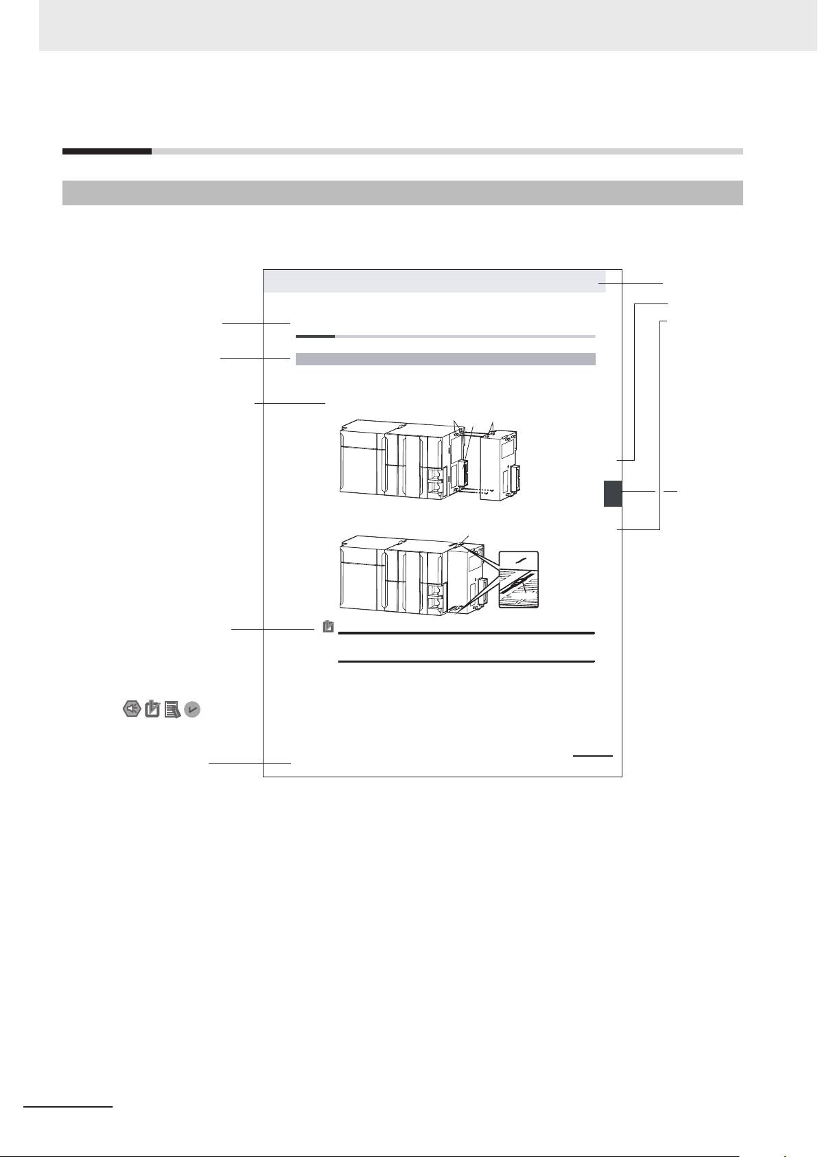
Level 1 heading
Level 2 heading
Level 3 heading
Level 2 heading
A step in a procedure
Manual name
Special information
Level 3 heading
Page tab
Gives the current
headings.
Indicates a procedure.
Icons indicate
precautions, additional
information, or reference
information.
Gives the number
of the main section.
The sliders on the tops and bottoms of the Power Supply Unit, CPU Unit, I/O Units, Special I/O
Units, and CP
U Bus Units must be completely locked (until they click into place) after connecting
the adjacent Unit connectors.
Manual Structure
Manual Structure
Page Structure
The following page structure is used in this manual.
Note This illustration is provided only as a sample. It may not literally appear in this manual.
4
NX-series NX102 CPU Unit Hardware User’s Manual (W593)
Page 7

Special Information
Special information in this manual is classified as follows:
Precautions for Safe Use
Precautions on what to do and what not to do to ensure safe usage of the product.
Precautions for Correct Use
Precautions on what to do and what not to do to ensure proper operation and performance.
Additional Information
Additional information to read as required.
This information is provided to increase understanding or make operation easier.
Manual Structure
Version Information
Information on differences in specifications and functionality for CPU Units with different unit
versions and for different versions of the Sysmac Studio is given.
Precaution on Terminology
In this manual, "download" refers to transferring data from the Sysmac Studio to the physical Control-
ler and
For the Sysmac Studio, "synchronization" is used to both "upload" and "download" data. Here,
"synchronize" means to automatically compare the data for the Sysmac Studio on the computer with
the data in the physical Controller and transfer the data in the direction that is specified by the user.
"upload
" refers to transferring data from the physical Controller to the Sysmac Studio.
NX-series NX102 CPU Unit Hardware User’s Manual (W593)
5
Page 8

Manual Structure
6
NX-series NX102 CPU Unit Hardware User’s Manual (W593)
Page 9

Sections in this Manual
1
2
3
4
5
1
2
3
4
5
A
Introduction to NX-series Controllers
System Configuration
Configuration Units
Designing the Power Supply System
Installation and W
iring
A
6
7
Appendices
6
7
Troubleshooting
Inspection and Maintenance
I
I
Index
Sections in this Manual
NX-series NX102 CPU Unit Hardware User’s Manual (W593)
7
Page 10

CONTENTS
CONTENTS
Introduction .............................................................................................................. 1
Intended Audience...........................................................................................................................................1
Applicable Products
Relevant Manuals..................................................................................................... 2
Manual Structure...................................................................................................... 4
Page Structure.................................................................................................................................................4
Special Information .......................................................................................................................................... 5
Precaution on Terminology ..............................................................................................................................5
Sections in this Manual ........................................................................................... 7
Terms and Conditions Agreement........................................................................ 12
Warranty, Limitations of Liability ....................................................................................................................12
Application Considerations ............................................................................................................................13
Disclaimers ....................................................................................................................................................13
.........................................................................................................................................1
Safety Precautions................................................................................................. 15
Definition of Precautionary Information.......................................................................................................... 15
Symbols ......................................................................................................................................................... 15
WARNING......................................................................................................................................................16
Cautions......................................................................................................................................................... 18
Precautions for Safe Use ...................................................................................... 20
Precautions for Correct Use ................................................................................. 31
Regulations and Standards .................................................................................. 35
Conformance to EU Directives ......................................................................................................................35
Conformance to UL and CSA Standards.......................................................................................................36
Conformance to KC Certification ...................................................................................................................36
Conformance to Shipbuilding Standards .......................................................................................................36
Software Licenses and Copyrights ................................................................................................................37
Versions.................................................................................................................. 38
Checking Versions.........................................................................................................................................38
Unit Versions of CPU Units and Sysmac Studio Versions.............................................................................40
Related Manuals..................................................................................................... 41
Terminology............................................................................................................ 44
Revision History..................................................................................................... 49
Section 1 Introduction to NX-series Controllers
1-1 The NX-series Controller.......................................................................................................1-2
1-1-1 Features
1-1-2 Introduction to the System Configurations ..................................................................................1-6
1-2 Specifications.........................................................................................................................1-9
1-3 Overall Operating Procedure for the CPU Unit ................................................................. 1-15
8
......................................................................................................................................1-3
NX-series NX102 CPU Unit Hardware User’s Manual (W593)
Page 11

1-3-1 Overall Procedure .....................................................................................................................1-15
1-3-2 Procedure Details
......................................................................................................................1-16
Section 2 System Configuration
2-1 Basic System Configuration.................................................................................................2-2
2-1-1 EtherCA
2-1-2 NX Unit Configuration .................................................................................................................2-4
T Network Configuration ................................................................................................2-3
2-2 Connecting to the Sysmac Studio........................................................................................2-6
2-3 Network Configuration .......................................................................................................... 2-7
Section 3 Configuration Units
3-1 CPU Units ...............................................................................................................................3-2
3-1-1 Models and Specifications
3-1-2 Part Names and Functions..........................................................................................................3-4
3-1-3 Operation Status Indicators.........................................................................................................3-6
3-1-4 Terminal Blocks ......................................................................................................................... 3-11
3-1-5 Battery .......................................................................................................................................3-12
3-1-6 ID Information Indication ...........................................................................................................3-13
3-2 SD Memory Cards................................................................................................................3-15
3-2-1 Models and Specifications ........................................................................................................3-15
3-2-2 Purpose .....................................................................................................................................3-15
3-3 Power Supply-related Units ................................................................................................ 3-16
3-4 NX Units................................................................................................................................3-17
3-5 Sysmac Studio ..................................................................................................................... 3-18
3-5-1 Model Numbers .........................................................................................................................3-18
3-5-2 Connection ................................................................................................................................3-18
..........................................................................................................3-2
CONTENTS
Section 4 Designing the Power Supply System
4-1 Power Supply System ...........................................................................................................4-2
4-1-1 NX Unit Power Supply and I/O Power Supply.............................................................................4-2
4-1-2 NX-series Power Supply-related Units ........................................................................................4-3
4-2 Designing the NX Unit Power Supply System...................................................................4-10
4-2-1 Procedure for Designing the NX Unit Power Supply System ....................................................4-10
4-2-2 Calculation Example for the NX Unit Power Supply..................................................................4-11
4-3 Designing the I/O Power Supply System...........................................................................4-13
4-3-1 I/O Power Supply Method .........................................................................................................4-13
4-3-2 Designing the I/O Power Supply from the NX Bus ....................................................................4-14
4-3-3 Designing the I/O Power Supply from External Sources...........................................................4-19
4-3-4 Restrictions on Inrush Current for ON/OFF Operation ..............................................................4-20
4-4 Selecting External Power Supplies and Protective Devices............................................4-21
4-4-1 Selecting the Unit Power Supply ...............................................................................................4-21
4-4-2 Selecting the I/O Power Supplies..............................................................................................4-23
4-4-3 Selecting Protective Devices.....................................................................................................4-24
Section 5 Installation and Wiring
5-1 Processing at Power ON and Power OFF............................................................................5-2
5-1-1 Power ON Operation
5-1-2 Power OFF Operation .................................................................................................................5-4
5-1-3 Resetting the Controller from the Sysmac Studio .......................................................................5-6
...................................................................................................................5-2
NX-series NX102 CPU Unit Hardware User’s Manual (W593)
9
Page 12

CONTENTS
5-2 Fail-safe Circuits....................................................................................................................5-7
5-3 Mounting and Removing Units
5-4 Wiring....................................................................................................................................5-41
5-5 Control Panel Installation....................................................................................................5-65
.............................................................................................5-9
5-3-1 Installation in a Control Panel ...................................................................................................5-10
5-3-2 Preparations for Installation ......................................................................................................5-14
5-3-3 Installing the CPU Unit ..............................................................................................................5-16
5-3-4 Attaching Markers .....................................................................................................................5-19
5-3-5 Installing and Connecting NX Units...........................................................................................5-20
5-3-6 Mounting the End Cover ...........................................................................................................5-24
5-3-7 Mounting the End Plates ...........................................................................................................5-25
5-3-8 Installing and Removing the SD Memory Card .........................................................................5-27
5-3-9 Battery Installation.....................................................................................................................5-32
5-3-10 Removing CPU Unit ..................................................................................................................5-35
5-3-11 Removing NX Units...................................................................................................................5-36
5-3-12 Assembled Appearance and Dimensions .................................................................................5-37
5-4-1 Wiring the Unit Power Supply ...................................................................................................5-42
5-4-2 Wiring the Additional NX Unit Power Supply Unit .....................................................................5-42
5-4-3 Wiring the Additional I/O Power Supply Unit .............................................................................5-42
5-4-4 Wiring the Protective Devices ...................................................................................................5-43
5-4-5 Grounding .................................................................................................................................5-44
5-4-6 Wiring the Built-in EtherCAT Port..............................................................................................5-49
5-4-7 Wiring the Built-in EtherNet/IP Port ...........................................................................................5-49
5-4-8 Wiring to the CPU Unit Terminal Block......................................................................................5-49
5-5-1 Temperature ..............................................................................................................................5-65
5-5-2 Humidity ....................................................................................................................................5-67
5-5-3 Vibration and Shock ..................................................................................................................5-67
5-5-4 Atmosphere ...............................................................................................................................5-67
5-5-5 Electrical Environment ..............................................................................................................5-68
5-5-6 Grounding .................................................................................................................................5-72
Section 6 Troubleshooting
6-1 Overview of Troubleshooting ...............................................................................................6-2
Section 7 Inspection and Maintenance
7-1 Cleaning and Maintenance....................................................................................................7-2
7-1-1 Cleaning
7-1-2 Periodic Inspections ....................................................................................................................7-3
7-1-3 Unit Replacement Precautions....................................................................................................7-4
......................................................................................................................................7-2
7-2 Replacing the Battery............................................................................................................7-6
Appendices
A-1 Specifications........................................................................................................................ A-2
A-2 Dimensions............................................................................................................................ A-3
A-2-1 NX-series NX102 CPU Unit ....................................................................................................... A-3
A-2-2 End Cover .................................................................................................................................. A-4
A-2-3 SD Memory Card ....................................................................................................................... A-4
A-3 List of Terminal Block Models ............................................................................................. A-5
A-3-1 Model Notation ........................................................................................................................... A-5
A-3-2 List of Terminal Block Models..................................................................................................... A-5
A-4 Version Information .............................................................................................................. A-7
A-4-1 Relationship between Unit Versions of CPU Units and Sysmac Studio Versions...................... A-7
A-4-2 Functions That Were Added or Changed for Each Unit Version................................................ A-8
10
NX-series NX102 CPU Unit Hardware User’s Manual (W593)
Page 13

Index
CONTENTS
A-5 Support Functions of the CPU Units and Restrictions on the NX Units........................ A-10
NX-series NX102 CPU Unit Hardware User’s Manual (W593)
11
Page 14

Terms and Conditions Agreement
Terms and Conditions Agreement
Warranty, Limitations of Liability
Warranties
Exclusive Warranty
l
Omron’s exclusive warranty is that the Products will be free from defects in materials and work-
manship for a period of twelve months from the date of sale by Omron (or such other period ex-
pressed in writing by Omron). Omron disclaims all other warranties, express or implied.
Limitations
l
OMRON MAKES NO WARRANTY OR REPRESENTATION, EXPRESS OR IMPLIED, ABOUT
NON-INFRINGEMENT, MERCHANTABILITY OR FITNESS FOR A PARTICULAR PURPOSE OF
THE PRODUCTS. BUYER ACKNOWLEDGES THAT IT ALONE HAS DETERMINED THAT THE
PRODUCTS WILL SUITABLY MEET THE REQUIREMENTS OF THEIR INTENDED USE.
Omron further disclaims all warranties and responsibility of any type for claims or expenses based
on infringement by the Products or otherwise of any intellectual property right.
Buyer Remedy
l
Omron’s sole obligation hereunder shall be, at Omron’s election, to (i) replace (in the form originally
shipped with Buyer responsible for labor charges for removal or replacement thereof) the non-com-
plying Product, (ii) repair the non-complying Product, or (iii) repay or credit Buyer an amount equal
to the purchase price of the non-complying Product; provided that in no event shall Omron be re-
sponsible for warranty, repair, indemnity or any other claims or expenses regarding the Products
unless Omron’s analysis confirms that the Products were properly handled, stored, installed and
maintained and not subject to contamination, abuse, misuse or inappropriate modification. Return
of any Products by Buyer must be approved in writing by Omron before shipment. Omron Compa-
nies shall not be liable for the suitability or unsuitability or the results from the use of Products in
combination with any electrical or electronic components, circuits, system assemblies or any other
materials or substances or environments. Any advice, recommendations or information given orally
or in writing, are not to be construed as an amendment or addition to the above warranty.
12
See http://www.omron.com/global/ or contact your Omron representative for published information.
Limitation on Liability; Etc
OMRON COMPANIES SHALL NOT BE LIABLE FOR SPECIAL, INDIRECT, INCIDENTAL, OR CON-
SEQUENTIAL DAMAGES, LOSS OF PROFITS OR PRODUCTION OR COMMERCIAL LOSS IN ANY
NX-series NX102 CPU Unit Hardware User’s Manual (W593)
Page 15

WAY CONNECTED WITH THE PRODUCTS, WHETHER SUCH CLAIM IS BASED IN CONTRACT,
WARRANTY
Further, in no event shall liability of Omron Companies exceed the individual price of the Product on
which liability is asserted.
, NEGLIGENCE OR STRICT LIABILITY.
Application Considerations
Suitability of Use
Omron Companies shall not be responsible for conformity with any standards, codes or regulations
which apply to the combination of the Product in the Buyer’
er’s request, Omron will provide applicable third party certification documents identifying ratings and
limitations of use which apply to the Product. This information by itself is not sufficient for a complete
determination of the suitability of the Product in combination with the end product, machine, system, or
other application or use. Buyer shall be solely responsible for determining appropriateness of the par-
ticular Product with respect to Buyer’s application, product or system. Buyer shall take application re-
sponsibility in all cases.
Terms and Conditions Agreement
s application or use of the Product. At Buy-
NEVER USE THE PRODUCT FOR AN APPLICATION INVOLVING SERIOUS RISK TO LIFE OR
PROPERTY OR IN LARGE QUANTITIES WITHOUT ENSURING THAT THE SYSTEM AS A WHOLE
HAS BEEN DESIGNED TO ADDRESS THE RISKS, AND THAT THE OMRON PRODUCT(S) IS
PROPERLY RATED AND INSTALLED FOR THE INTENDED USE WITHIN THE OVERALL EQUIP-
MENT OR SYSTEM.
Programmable Products
Omron Companies shall not be responsible for the user’s programming of a programmable Product, or
any consequence thereof.
Disclaimers
Performance Data
Data presented in Omron Company websites, catalogs and other materials is provided as a guide for
the user in determining suitability and does not constitute a warranty. It may represent the result of
Omron’
formance is subject to the Omron’s Warranty and Limitations of Liability.
s test conditions, and the user must correlate it to actual application requirements. Actual per-
Change in Specifications
Product specifications and accessories may be changed at any time based on improvements and oth-
er reasons. It is our practice to change part numbers when published ratings or features are changed,
or when significant construction changes are made. However, some specifications of the Product may
NX-series NX102 CPU Unit Hardware User’s Manual (W593)
13
Page 16

Terms and Conditions Agreement
be changed without any notice. When in doubt, special part numbers may be assigned to fix or estab-
lish key specifications for your application. Please consult with your Omron’s representative at any
time to confirm actual specifications of purchased Product.
Errors and Omissions
Information presented by Omron Companies has been checked and is believed to be accurate; how-
ever, no responsibility is assumed for clerical, typographical or proofreading errors or omissions.
14
NX-series NX102 CPU Unit Hardware User’s Manual (W593)
Page 17
Safety Precautions
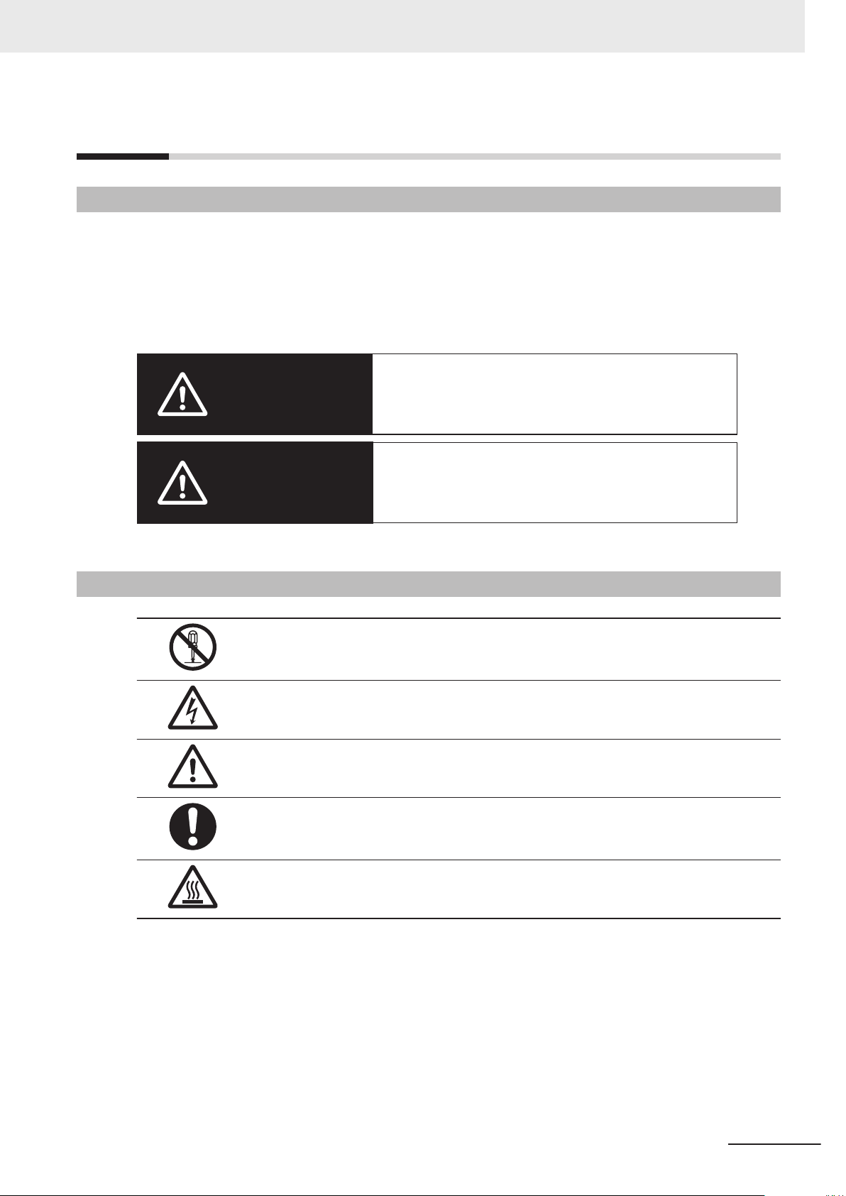
Indicates a potentially hazardous situation which, if
not avoided, could result in death or serious injury.
Additionally, there may be severe property
damage.
Indicates a potentially hazardous situation which, if
not avoided, may result in minor or moderate
injury, or property damage.
WARNING
Ca
ution
Definition of Precautionary Information
The following notation is used in this manual to provide precautions required to ensure safe usage of
the NX-series CPU Unit.
The safety precautions that are provided are extremely important for safety. Always read and heed the
information provided in all safety precautions.
The following notation is used.
Safety Precautions
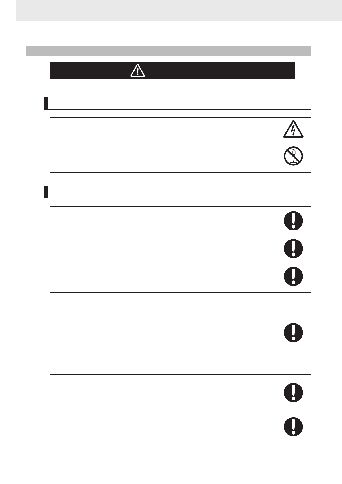
Symbols
The circle and slash symbol indicates operations that you must not do.
The specific operation is shown in the circle and explained in text.
This example indicates prohibiting disassembly
The triangle symbol indicates precautions (including warnings).
The specific operation is shown in the triangle and explained in text.
This example indicates a precaution for electric shock.
The triangle symbol indicates precautions (including warnings).
The specific operation is shown in the triangle and explained in text.
This example indicates a general precaution.
The filled circle symbol indicates operations that you must do.
The specific operation is shown in the
This example shows a general precaution for something that you must do.
The triangle symbol indicates precautions (including warnings).
The specific operation is shown in the triangle and explained in text.
This example indicates a precaution for high temperatures.
circle and explained in text.
.
NX-series NX102 CPU Unit Hardware User’s Manual (W593)
15
Page 18
WARNING
Safety Precautions
WARNING
During Power Supply
Do not touch any of the terminals or terminal blocks while the power is being supplied.
Doing so may result in electric shock.
Do not attempt to take any Unit apart.
In particular, high-voltage parts are present in the Power Supply Unit while power is
supplied or immediately after power is turned OFF
result in electric shock. There are sharp parts inside the Unit that may cause injury.
. Touching any of these parts may
Fail-safe Measures
Provide safety measures in external circuits to ensure safety in the system if an abnormality occurs due to malfunction of the CPU Unit, slaves, or Units or due to other external factors affecting operation. Not doing so may result in serious accidents due to
incorrect operation.
Emergency stop circuits, interlock circuits, limit circuits, and similar safety measures
must be provided in external control circuits.
The Controller outputs may remain ON or OFF due to deposition or burning of the output relays or destruction of the output transistors. As a countermeasure for such problems, external safety measures must be provided to ensure safe operation of the system.
The CPU Unit will turn OFF digital outputs on the CPU Rack in the following cases.
• While the CPU Unit is on standby until RUN mode is entered after the power is
turned ON
If an error occurs in the power supply
•
• If a system initialization error occurs
Digital outputs on the CPU Rack will produce outputs according to the settings in the
following cases.
• If a CPU Unit error or CPU Unit reset occurs
• If a major fault level Controller error occurs
External safety measures must be provided to ensure safe operation of the system in
such cases.
If there is interference in remote I/O communications or if a major fault level error occurs, output status will depend on the products that are used.
Confirm the operation that will occur when there is interference in communications or a
major fault level error, and implement safety measures.
Correctly set all of the settings in the slaves and Units.
If external power supplies for Units, slaves or other devices are overloaded or shortcircuited, the voltage will drop, outputs will turn OFF, and the system may be unable to
read inputs. Provide external safety measures in controls with monitoring of external
power supply voltage as required so that the system operates safely in such a case.
16
NX-series NX102 CPU Unit Hardware User’s Manual (W593)
Page 19
Safety Precautions
Unintended outputs may occur when an error occurs in variable memory. As a countermeasure for such problems, external safety measures must be provided to ensure safe
operation of the system.
Provide measures in the communications system and user program to ensure safety in
the overall system even if errors or malfunctions occur in data link communications or
remote I/O communications.
The NX-series Controller continues normal operation for a certain period of time when
a momentary power interruption occurs. This means that the NX-series Controller may
receive incorrect signals from external devices that are also affected by the power interruption.
Accordingly, take suitable actions, such as external fail-safe measures and interlock
conditions, to monitor the power supply voltage of the external device as required.
You must take fail-safe measures to ensure safety in the event of incorrect, missing, or
abnormal signals caused by broken signal lines, momentary power interruptions, or
other causes.
Not doing so may result in serious accidents due to incorrect operation.
Voltage and Current Inputs
Make sure that the voltages and currents that are input to the slaves and Units are
within the specified ranges.
Inputting voltages or currents that are outside of the specified ranges may cause accidents or fire.
Downloading
Always confirm safety at the destination before you transfer a user program, configuration data, setup data, or device variables from the Sysmac Studio.
The devices or machines may perform unexpected operation regardless of the operating mode of the CPU Unit.
Actual Operation
Check the user program, data, and parameter settings for proper execution before you
use them for actual operation.
NX-series NX102 CPU Unit Hardware User’s Manual (W593)
17
Page 20
Caution
Internal
power supply
circuit
(No-isola-
tion)
CPU Unit
Cable
External device
(e.g. computer)
External power supply (Unit power supply)
Non-isolated type Communication Interface Unit, etc.
Unit power
supply
terminals
Non-isolated DC
power supply
Safety Precautions
Cautions
Application
Do not touch any Unit when power is being supplied or immediately after the power
supply is turned OFF. Doing so may result in burn injury
Wiring
Be sure that all terminal screws and cable connector screws are tightened to the torque specified in the relevant manuals. The loose screws may result in fire or malfunction.
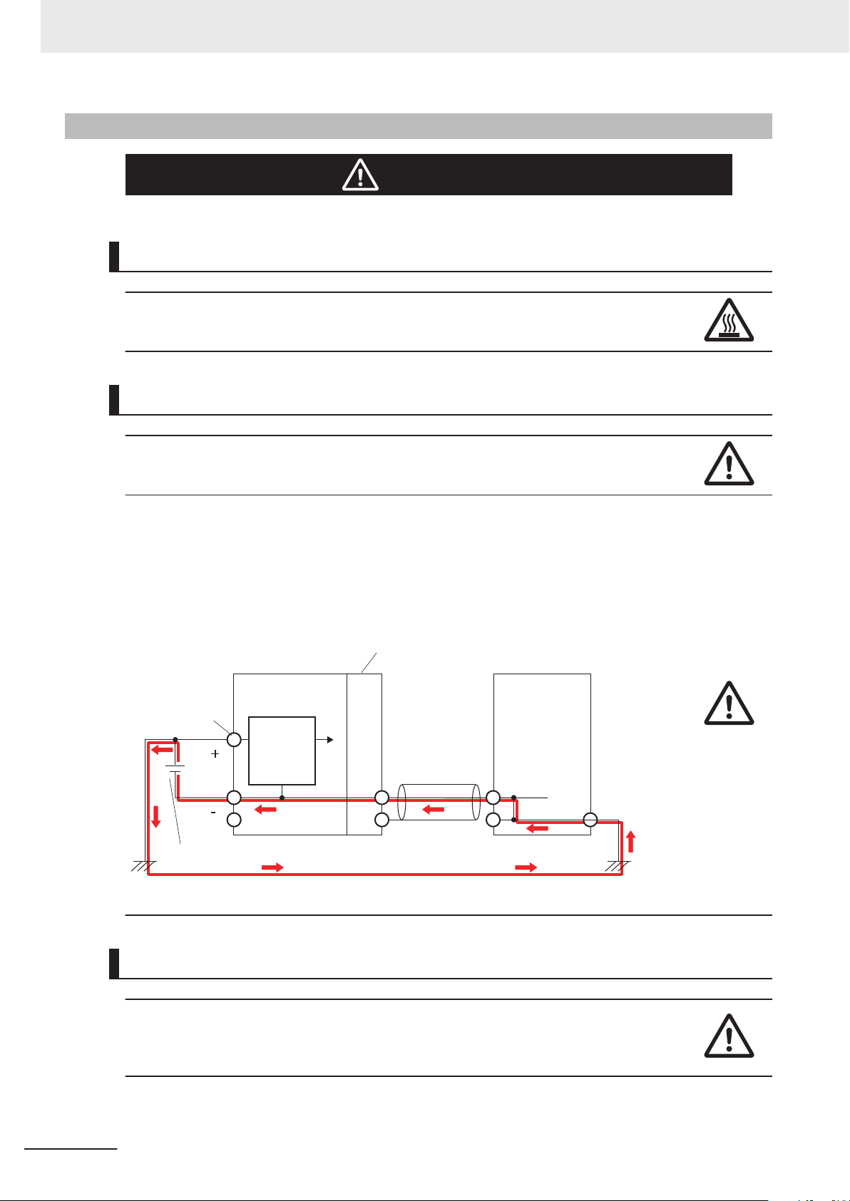
When you connect a computer or other peripheral device to a Controller that has a
non-isolated DC power supply, either ground the 0-V side of the external power supply
for the Unit power supply or do not ground it at all.
If the peripheral devices are grounded incorrectly, the external power supply for the
Unit power supply may be short-circuited. Never ground the 24-V side of the power
supply, as shown in the following figure.
.
Online Editing
18
Execute online editing only after confirming that no adverse effects will be caused by
deviations in the timing of I/O. If you perform online editing, the task execution time
may exceed the task period, I/O may not be refreshed with external devices, input signals may not be read, and output timing may change.
NX-series NX102 CPU Unit Hardware User’s Manual (W593)
Page 21

Safety Precautions
EtherCAT Communications
If the cable redundancy function is enabled, always write a program to confirm that the
network is in the cable redundancy status. If the program is not written, you cannot
check that the network is not in the cable redundancy status due to a disconnection on
the ring topology.
Use the _EC_RingBreaking system-defined variable to confirm that the network is in
the cable redundancy status.
Version Information
The cable redundancy function can be used with project unit version 1.40 or later.
NX-series NX102 CPU Unit Hardware User’s Manual (W593)
19
Page 22
Precautions for Safe Use
Precautions for Safe Use
Transporting and Disassembly
• Do not attempt to disassemble, repair, or modify any Units. Doing so may result in malfunction or
fire.
• Do not drop any Unit or subject it to abnormal vibration or shock. Doing so may result in Unit mal-
function or burning.
• When transporting any Unit, use the special packing box for it. Also, do not subject the Unit to ex-
cessive vibration or shock during transportation.
Mounting
• Always turn OFF the power supply before mounting the Units. If the power supply is not OFF, the
Unit may result in malfunction or may be damaged.
• Do not apply labels or tape to the Unit. When the Unit is installed or removed, adhesive or scraps
may adhere to the pins in the NX bus connector, which may result in malfunctions.
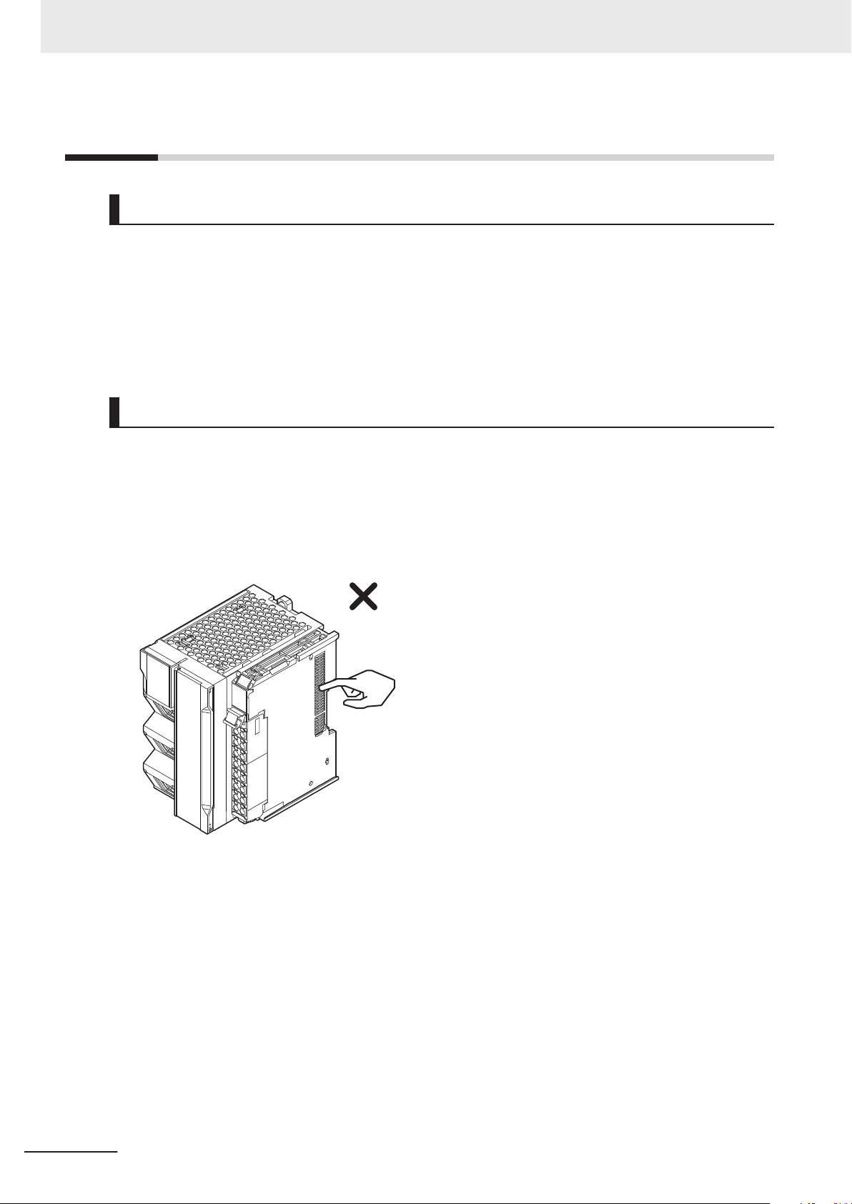
• Do not touch the pins in the NX bus connector on the Unit. Dirt may adhere to the pins in the NX bus
connector, which may result in malfunctions.
20
• Do not write on the CPU Unit with ink within the restricted region that is shown in the following fig-
ure. Also do not get this area dirty. When the Unit is installed or removed, ink or dirt may adhere to
the pins in the NX bus connector
Refer to the user’s manual for the connected NX Unit for information on the restricted region for the
NX Unit.
, which may result in malfunctions in the Unit.
NX-series NX102 CPU Unit Hardware User’s Manual (W593)
Page 23
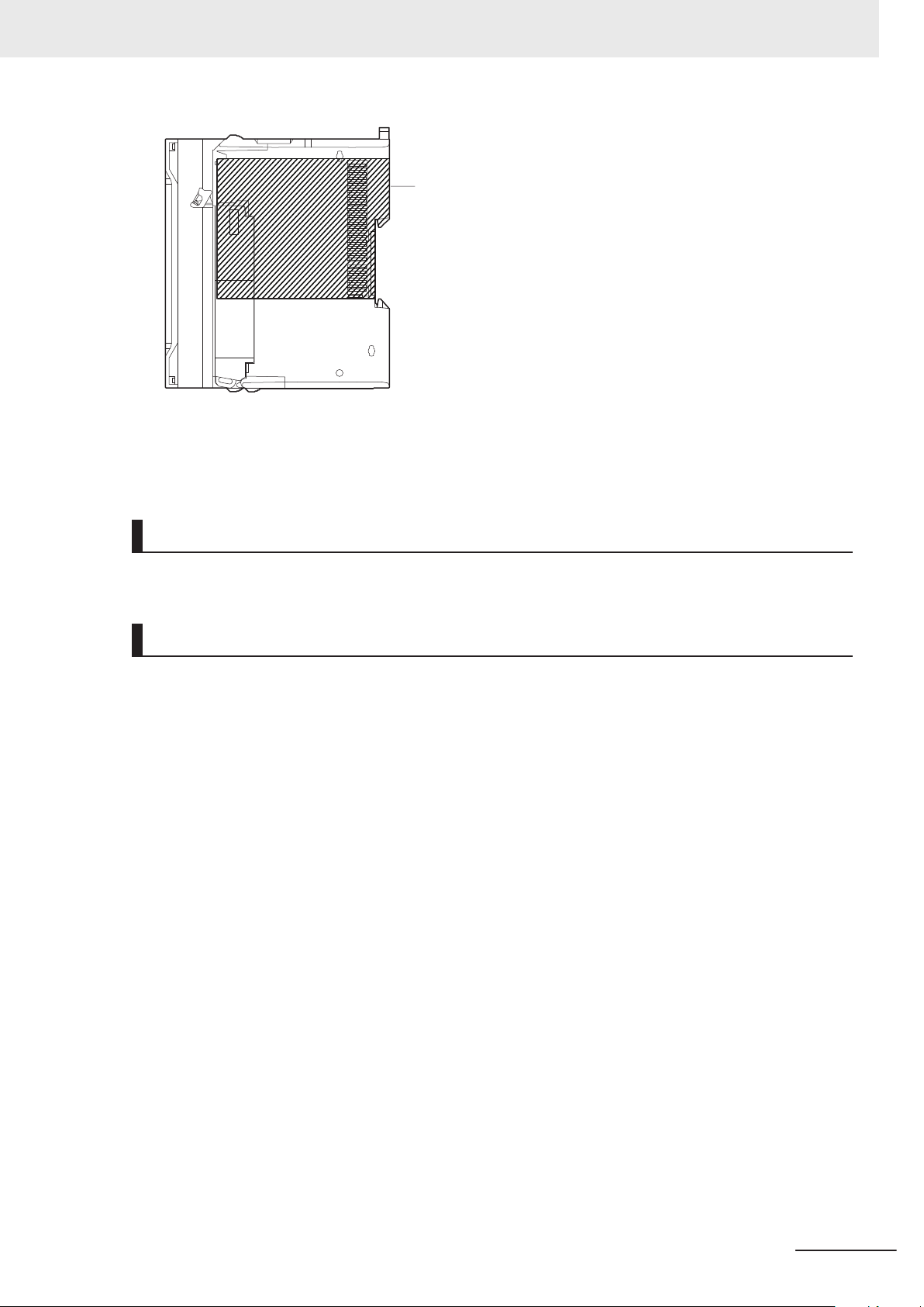
Restricted region
(shaded portion)
Precautions for Safe Use
• The End Cover has a metal portion and is heavier than it looks. Be careful not to drop it when han-
dling.
Installation
• Always connect to a ground of 100 Ω or less when installing the Units.
Wiring
• Follow the instructions in this manual to correctly perform wiring.
Double-check all wiring and switch settings before turning ON the power supply.
•
Use the methods that are specified in this manual for wiring the terminal blocks.
• Use crimp terminals for wiring the M3 screw terminal blocks. Do not connect bare stranded wires
directly to the M3 screw terminal blocks.
• Use the correct wiring parts and tools when you wire the system. Otherwise, cables may be discon-
nected to cause short-circuit or wire breakage.
• Do not pull on the cables or bend the cables beyond their natural limit.
Do not place heavy objects on top of the cables or other wiring lines. Doing so may break the ca-
bles.
• Mount terminal blocks, connectors, and other parts only after checking the mounting location care-
fully.
• Be sure that the terminal blocks and communications cables with tightening screws or locking devi-
ces are properly tightened to or locked into place.
• If the external power supply to an Output Unit or slave has polarity, connect it with the correct polari-
ty. If the polarity is reversed, current may flow in the reverse direction and damage the connected
devices regardless of the operation of the Controller.
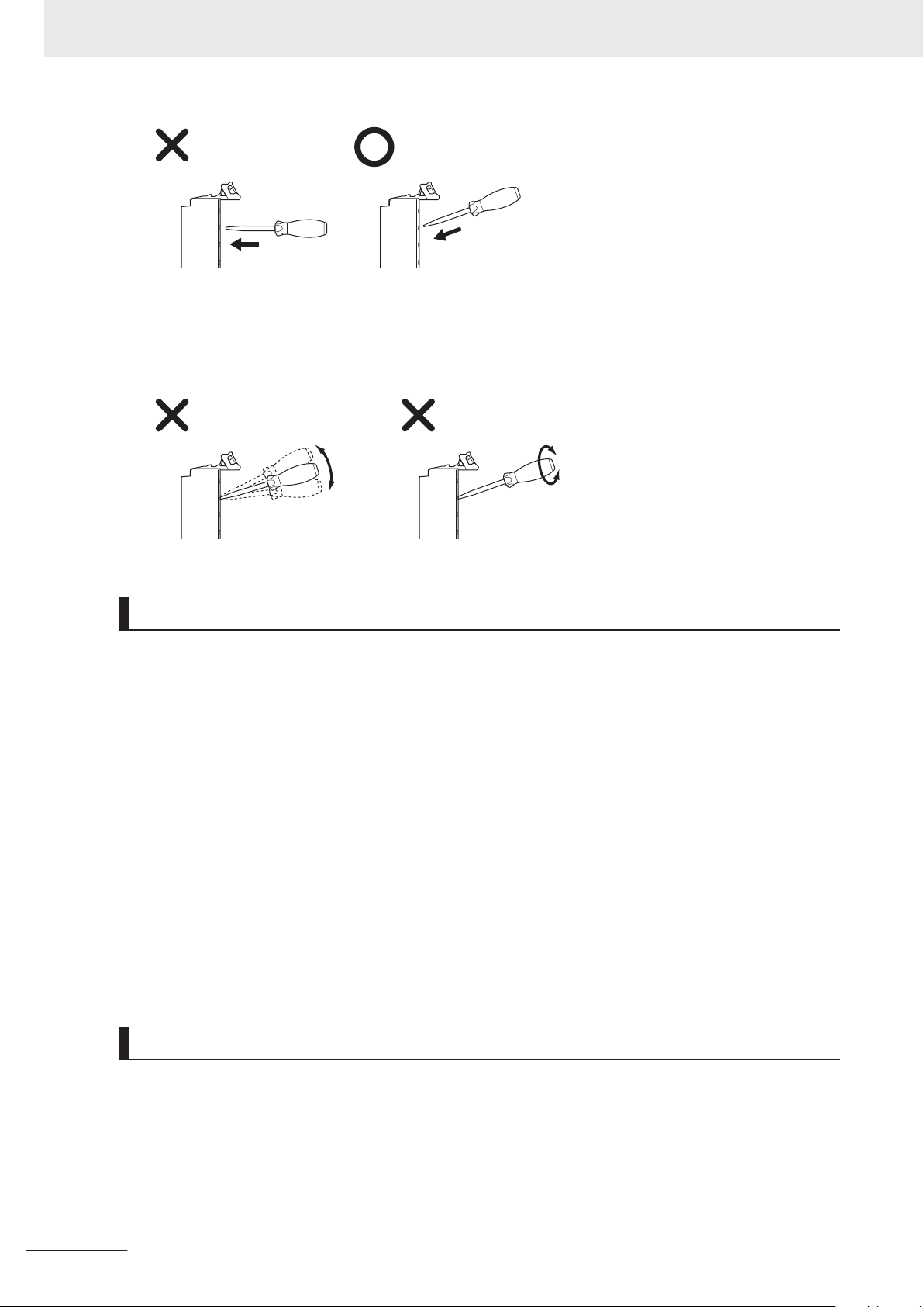
• Do not press a flat-blade screwdriver straight into the release hole on a screwless clamping terminal
block. Doing so may break the terminal block.
NX-series NX102 CPU Unit Hardware User’s Manual (W593)
21
Page 24
Precautions for Safe Use
• When you insert a flat-blade screwdriver into a release hole on a screwless clamping terminal block,
press it down with a force of 30N or less. Applying excessive force may damage the terminal block.
• Do not incline or twist the flat-blade screwdriver while it is in a release hole on a screwless clamping
terminal block. Doing so may break the terminal block.
Power Supply Design
• Select an external power supply with sufficient capacity by considering the power supply capacity or
inrush current when the power is turned ON that is specified in this manual.
Otherwise, the external power supply may not be turned ON or malfunction due to unstable power
supply voltage.
• Use all Units within the I/O power supply ranges that are given in the specifications.
•
Do not apply voltages that exceed the rated value to any Input Unit.
• Do not apply voltages or connect loads to the Output Units or slaves in excess of their ratings.
• Surge current occurs when the power supply is turned ON. When selecting fuses or breakers for
external circuits, consider the above precaution and allow sufficient margin in shut-off performance.
Refer to this manual for surge current specifications.
• If the full dielectric strength voltage is applied or turned OFF using the switch on the tester, the gen-
erated impulse voltage may damage the Power Supply Unit. Use the adjustment on the tester to
gradually increase and decrease the voltage.
• Install external breakers and take other safety measures against short-circuiting and overcurrents in
external wiring.
Turning ON the Power Supply
22
• It takes approximately 20 seconds to enter RUN mode after the power supply is turned ON. During
that time, digital outputs on the CPU Rack will be OFF. The slave outputs behave according to the
setting values.
Use the system-defined variables and the NX Unit device variables in the user program to confirm
that I/O data communications are established before attempting control operations. External com-
munications are also not performed during startup.
NX-series NX102 CPU Unit Hardware User’s Manual (W593)
Page 25

Precautions for Safe Use
• Configure the external circuits so that the power supply to the control system turns ON only after the
power supply to the Controller has turned ON. If the power supply to the Controller is turned ON
after the control power supply, temporary errors may result in incorrect control system signals be-
cause the output terminals on Output Units may momentarily turn ON when power supply is turned
ON to the Controller
• If you transfer data from a backup file on an SD Memory Card to the Controller when the power sup-
ply is turned ON, properly select the data groups to transfer. If the data for an unintended data group
is transferred to the Controller, it may cause the equipment to operate unpredictably.
• You cannot obtain normal input data from NX Units while the Units are restarting. Use the system-
defined variables or device variables for the NX Units on the CPU Unit in the user program to check
the validity of the I/O data before you attempt control operations.
.
Actual Operation
• If you change the fail-soft operation setting, the output status when the error occurs may also
change. Confirm safety before you change the setting.
• If you use fail-soft operation, write programming to determine whether Unit I/O data is valid. Without
such programming, the user program cannot distinguish between Units for which I/O refreshing is
continued and Units for which I/O refreshing is stopped.
Turning OFF the Power Supply
• Never turn OFF the power supply to the Controller when the BUSY indicator is flashing. While the
BUSY indicator is lit, the user program and settings in the CPU Unit are being backed up in the built-
in non-volatile memory. This data will not be backed up correctly if the power supply is turned OFF.
Also, a major fault level Controller error will occur the next time you start operation, and operation
will stop.
•
Do not turn OFF the power supply or remove the SD Memory Card while SD Memory Card access
is in progress (i.e., while the SD BUSY indicator flashes). Data may become corrupted, and the
Controller will not operate correctly if it uses corrupted data. To remove the SD Memory Card from
the CPU Unit while the power supply is ON, press the SD Memory Card power supply switch and
wait for the SD BUSY indicator and SD PWR indicator to turn OFF before you remove the SD Mem-
ory Card.
• If the Unit power supply is turned OFF before the I/O power supply for the control system is turned
OFF, the output terminals of Output Units may malfunction and the control system may perform in-
correct output temporarily. To avoid this problem, configure the external circuit to make sure that the
Unit power supply is turned OFF only after the power supply for the control system is turned OFF.
• Do not disconnect the cable or turn OFF the power supply to the Controller when downloading data
or the user program from Support Software.
• Always turn OFF the power supply to the Controller before you attempt any of the following.
a) Mounting or removing the Units
b) Assembling the Units
c) Setting DIP switches or rotary switches
d) Connecting cables or wiring the system
e) Connecting or disconnecting the terminal blocks or connectors
NX-series NX102 CPU Unit Hardware User’s Manual (W593)
23
Page 26

Precautions for Safe Use
The power supply circuit in the CPU Unit may continue to supply power to the Controller for a few
seconds after the power supply turns OFF. The POWER indicator is lit during this time. Confirm that
the POWER indicator is not lit before you perform any of the above actions.
Operation
• Confirm that no adverse effect will occur in the system before you attempt any of the following.
a) Changing the operating mode of the CPU Unit (including changing the setting of the Startup
Mode)
b) Changing the user program or settings
c) Changing set values or present values
d) Forced refreshing
e) Starting the CPU Unit with the battery exhausted
f) Restarting a slave or Unit after you change any settings
g) Transferring a backup file on the SD Memory Card
• After you change any slave or Unit settings, carefully check the safety of the controlled system be-
fore you restart the Unit.
•
If two different function modules are used together, such as when you use EtherNet/IP and Ether-
CAT slaves, take suitable measures in the user program and external controls to ensure that safety
is maintained in the controlled system if one of the function modules stops. The relevant outputs will
behave according to the slave or Unit specifications if a partial fault level error occurs in one of the
function modules.
• Always confirm safety at the connected equipment before you reset Controller errors with an event
level of partial fault or higher for the EtherCAT Master Function Module.
When the error is reset, all slaves that were in any state other than Operational state due to a Con-
troller error with an event level of partial fault or higher (in which outputs are disabled) will go to Op-
erational state and the outputs will be enabled.
Before you reset all errors or restart a slave, confirm that no Controller errors with an event level of
partial fault have occurred for the EtherCAT Master Function Module.
24
Designing Tasks
• If the following variables are specified for a condition expression when the execution condition of
event tasks is the same as the condition expression for a variable, event tasks may not be executed
when conditions are met, or event tasks may be executed when conditions are not met.
a) Structure members whose data size is 16 bits or more, except for system-defined variables for
motion control
b) Array elements whose data size is 16 bits or more
Refer to the NJ/NX-series CPU Unit Software User’
event task execution conditions.
s Manual (Cat. No. W501) for information on
Battery Backup
• If you use the clock data in the user program and turn OFF the power supply for a long time, use a
Battery which is sold separately.
NX-series NX102 CPU Unit Hardware User’s Manual (W593)
Page 27

Precautions for Safe Use
The Battery is not mounted when the product is at factory setting. The clock data is retained by the
built-in capacitor. The capacitor is charged while the power is supplied and discharged while the
power is not supplied. If the power OFF time rate is high, the clock data is initialized and malfunc-
tions may occur in the program for which the clock data is used.
•
If you use the Battery, connect the Sysmac Studio and set the Battery-related error detection to
Use. The Battery-related error detection is set to Do not use at the factory setting because the
Battery is not built in. If the Battery-related error detection is set to Do not use, an error cannot be
detected when the Battery is exhausted and malfunctions may occur in the program for which the
clock data is used.
Debugging
• Forced refreshing ignores the results of user program execution and refreshes I/O with the specified
values. If forced refreshing is used for inputs for which I/O refreshing is not supported, the inputs will
first take the specified values, but they will then be overwritten by the user program. Be careful that
this operation differs from the force-set/reset functionality of the CJ/CP-series PLCs.
•
You cannot upload or download information for forced refreshing with the Sysmac Studio.
After downloading data that contains forced refreshing, change to RUN mode and then use the Sys-
mac Studio to perform the operation for forced refreshing.
Depending on the difference in the forced status, the control system may operate unexpectedly.
• Do not specify the same address for the AT specification for more than one variable.
Doing so would allow the same entity to be accessed with different variable names, which would
make the user program more difficult to understand and possibly cause programming mistakes.
General Communications
• When you use data link communications, check the error information that is given in _ErrSta (Con-
troller Error Status) to make sure that no error has occurred in the source device. Create a user pro-
gram that uses reception data only when there is no error in the source device.
If there is an error in the source device, the data for the data link may contain incorrect values.
• Unexpected operation may result if inappropriate data link tables are set. Even if appropriate data
link tables have been set, confirm that the controlled system will not be adversely affected before
you transfer the data link tables. The data links start automatically after the data link tables are
transferred.
EtherNet/IP Communications
• Make sure to use the communications distance, number of nodes connected, and method of con-
nection for EtherNet/IP within specifications. Do not connect EtherNet/IP communications to Ether-
CAT or other networks. An overload may cause the network to fail or malfunction.
•
All related EtherNet/IP nodes are reset when you transfer settings for the built-in EtherNet/IP port
(including IP addresses and tag data links settings). The settings can only be enabled after the re-
set. Confirm that the system will not be adversely affected by resetting nodes before you transfer the
settings.
• If EtherNet/IP tag data links (cyclic communications) are used with a repeating hub, the communica-
tions load on the network will increase. This will increase collisions and may prevent stable
NX-series NX102 CPU Unit Hardware User’s Manual (W593)
25
Page 28

Precautions for Safe Use
communications. Do not use repeating hubs on networks where tag data links are used. Use an
Ethernet switch instead.
EtherCAT Communications
• Make sure to use the communications distance, number of nodes connected, and method of con-
nection for EtherCAT within specifications.
Do not connect EtherCA
works. An overload may cause the network to fail or malfunction.
• Malfunctions or unexpected operation may occur for some combinations of EtherCAT revisions of
the master and slaves. If you disable the revision check in the network settings, use the Sysmac
Studio to check the slave revision settings in the master and the actual slave revisions, and then
make sure that functionality is compatible in the slave manuals or other references. You can check
the actual slave revisions from the Sysmac Studio or on slave nameplates.
• After you transfer the user program, the CPU Unit is restarted and communications with the Ether-
CAT slaves are cut off. During that period, the slave outputs behave according to the slave specifi-
cations. The time that communications are cut off depends on the EtherCAT network configuration.
Before you transfer the user program, confirm that the system will not be adversely affected.
• If the Fail-soft Operation Setting is set to Stop, process data communications will stop for all
slaves when an EtherCAT communications error is detected in a slave. At that time, the Servo Drive
will operate according to the Servo Drive specifications. Make sure that the Fail-soft Operation
setting results in safe operation when a device error occurs.
• Even if the Process Data Communication is stopped and subsequently restored automatically, take
the external safety measures or set the Fail-soft Operation Settings to Stop to make the system op-
erate safe.
• EtherCAT communications are not always established immediately after the power supply is turned
ON. Use the system-defined variables in the user program to confirm that communications are es-
tablished before attempting control operations.
• If noise occurs or an EtherCAT slave is disconnected from the network, any current communications
frames may be lost. If frames are lost, slave I/O data is not communicated, and unintended opera-
tion may occur. The slave outputs will behave according to the slave specifications. Refer to the
manual for the slave. If a noise countermeasure or slave replacement is required, perform the fol-
lowing processing.
a) Program the Input Data Invalid system-defined variable as an interlock condition in the user pro-
gram.
b) Set the PDO communications timeout detection count setting in the EtherCAT master to at
least 2. Refer to the NJ/NX-series CPU Unit Built-in EtherCAT Port User’s Manual (Cat. No.
W505) for details.
• When an EtherCAT slave is disconnected, communications will stop and control of the outputs will
be lost not only for the disconnected slave, but for all slaves connected after it through to the physi-
cal end node. Confirm that the system will not be adversely affected before you disconnect a slave.
• I/O data communications of NX bus are not always established immediately after the power supply
is turned ON. Use the system-defined variables and the EtherCAT Coupler Unit device variables in
the user program to confirm that I/O data communications are established before attempting control
operations.
• You cannot use standard Ethernet hubs or repeater hubs with EtherCAT communications. If you use
one of these, a major fault level error or other error may occur.
T communications to EtherNet/IP, a standard in-house LAN, or other net-
26
NX-series NX102 CPU Unit Hardware User’s Manual (W593)
Page 29

Precautions for Safe Use
• If the actual configuration changes, for example, when actual configuration does not contain a disa-
ble slave and subsequently you include it in the actual configuration, set the total cable length for the
case of the worst scenario.
• Confirm that all of the slaves are connected before you set the transmission delay time by the actual
measurement. If the transmission delay time is exceeded from the set values due to the changes of
the unit configuration, such as when the disabled salve is connected to the actual configuration after
the setting, it may cause illegal communications with slaves.
•
When the communications cable that is connected to the slave from other manufacturers on the ring
topology is broken or the power supply to the slave from other manufacturers is interrupted, any cur-
rent communications frames may be lost.
If frames are lost, slave I/O data is not communicated, and unintended operation may occur.
When slaves from other manufacturers are connected on the ring topology, check the followings in
advance.
a) Disconnect and connect communications cables that are connected to the output ports of slaves
from other manufacturers several times, and there is no error except for a Ring Disconnection
Detected.
b) Disconnect and connect communications cables that are connected to the input ports of slaves
from other manufacturers several times, and there is no error except for a Ring Disconnection
Detected.
c) Turn OFF and ON the power supply to the slaves from other manufacturers, and there is no er-
ror except for a Illegal Slave Disconnection Detected.
• If you use the cable redundancy function, confirm that the task execution time is within the task peri-
od while the cable for the end port of the ring is disconnected. When a disconnection occurred on
the ring topology, the transmission delay time is increased and the task execution time may be lon-
ger.
Version Information
The cable redundancy function can be used with project unit version 1.40 or later.
Motion control
• Confirm the axis number carefully before you perform an MC Test Run.
• The motor is stopped if communications are interrupted between the Sysmac Studio and the CPU
Unit during an MC T
Unit securely and confirm that the system will not be adversely affected before you perform an MC
Test Run.
• Always execute the Save Cam Table instruction if you change any of the cam data from the user
program in the CPU Unit or from the Sysmac Studio. If the cam data is not saved, the previous con-
dition will be restored when the power is turned ON again, possibly causing unexpected machine
operation.
• The positive drive prohibit input (POT), negative drive prohibit input (NOT), and home proximity in-
put (DEC) of the Servo Drive are used by the MC Function Module as the positive limit input, nega-
tive limit input, and home proximity input. Make sure that the signal widths for all of these input sig-
nals are longer than the control period of the MC Function Module. If the input signal widths are
shorter than the control period, the MC Function Module may not be able to detect the input signals,
resulting in incorrect operation.
est Run. Connect the communications cable between the computer and CPU
NX-series NX102 CPU Unit Hardware User’s Manual (W593)
27
Page 30
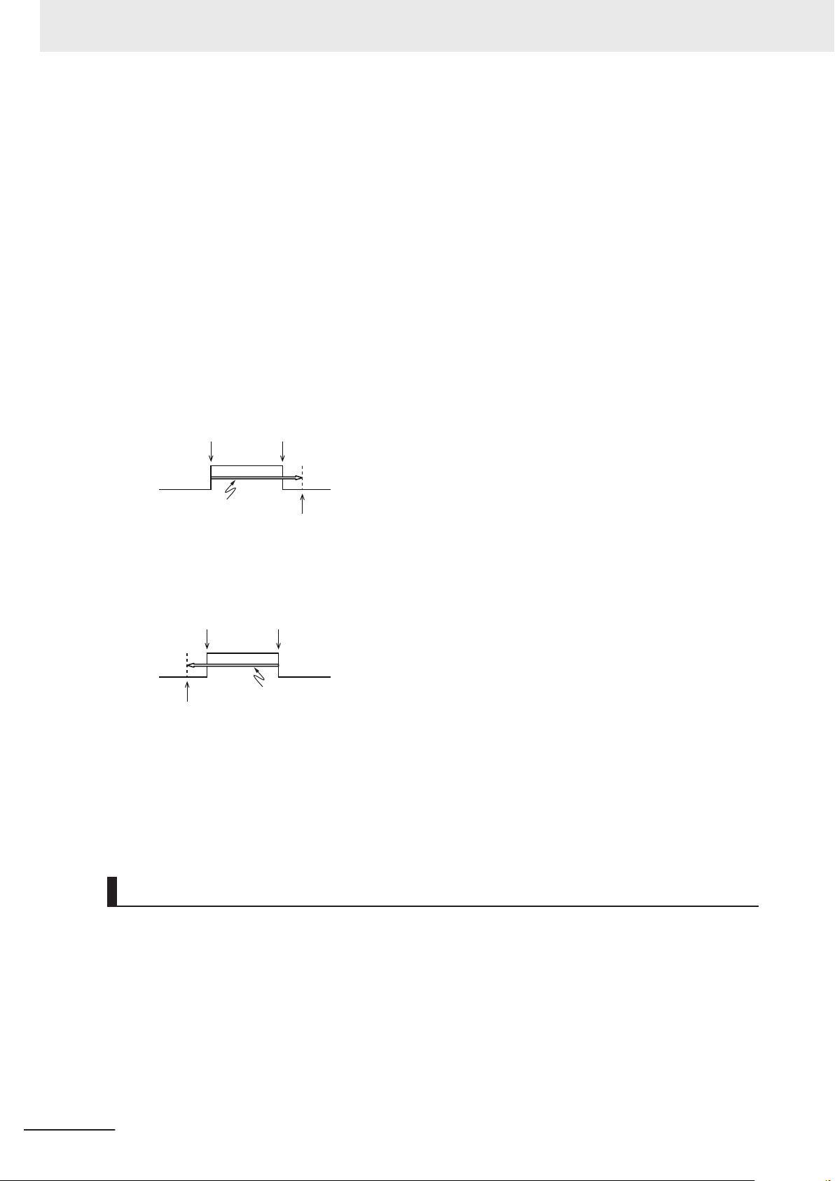
FirstOnPosition LastOnPosition
OnCompensation
FirstOnPosition
after compensation
FirstOnPosition LastOnPosition
OffCompensation
LastOnPosition
after compensation
Precautions for Safe Use
• If you make any changes in the Detailed Settings Area of the Axis Basic Settings Display of the
Sysmac Studio, make sure that the devices or machines perform the expected operation before you
start actual operation.
If the relationship between the functions of the Motion Control Function Module and the EtherCAT
slave process data that is assigned to the axes is not correct, the devices or machines may perform
unexpected operation.
•
Always use the axis at a constant velocity for the MC_DigitalCamSwitch (Enable Digital Cam
Switch) instruction.
If you set the Count Mode to Rotary Mode, the following operation will occur if you use OnCompen-
sation or OffCompensation and the axis velocity changes abruptly.
a) If the value of OnCompensation or OffCompensation is equivalent to the time for half a rotation
or more, InOperation will be FALSE.
b) If the value of OnCompensation results in exceeding LastOnPosition, the output timing will be
unstable.
c) If the value of OffCompensation results in exceeding FirstOnPosition, the output timing will be
unstable.
• Use the NX_AryDOutTimeStamp (Write Digital Output Array with Specified Time Stamp) instruction
only after you confirm that InOperation from the MC_DigitalCamSwitch (Enable Digital Cam Switch)
instruction is TRUE.
• If you change the unit conversion settings, perform homing again. If you do not perform homing, un-
intended operation of the controlled system may occur
Backing Up Data
• Backup function allows to save various setting data in the Controller to an SD Memory Card or a
computer.
If you back up data when the operating mode is set to the RUN mode, the concurrency of variables
with a Retain attribute (i.e., structure and array variables of two bytes or more) may be lost.
T
o ensure data concurrency, we recommend that you back up data when the operating mode is set
to PROGRAM mode.
• We recommend that you back up the present values of variables while the retained variables are not
refreshed.
.
28
NX-series NX102 CPU Unit Hardware User’s Manual (W593)
Page 31

Precautions for Safe Use
If you back up variables while the values of retained variables are refreshed, the data may not be
saved correctly.
Refer to the
backup function and backing up the present values of variables.
NJ/NX-series CPU Unit Software User’s Manual (Cat. No. W501) for details on the
Restoring Data
• You cannot back up, restore, or compare some or all of the settings for certain slaves and Units.
Also, you cannot back up, restore, or compare data for disabled slaves or Units. After you restore
data, sufficiently confirm that operation is correct before you start actual operation.
•
If any of the following conditions is met, clear the absolute encoder home offsets from the list of data
items to restore, and then restore the data. Then, define the absolute encoder home again. If you do
not define home, unintended operation of the controlled system may occur.
a) The Servomotor or Servo Drive was changed since the data was backed up.
b) The absolute encoder was set up after the data was backed up.
c) The absolute data for the absolute encoder was lost.
Transferring Programs
• When you use the program transfer from SD Memory Card whose Startup Mode setting is set to
RUN mode, the operating mode changes to RUN after the transfer is completed regardless of the
status and setting before the transfer. Use this function after you confirm that system startup does
not cause any problem.
•
Always confirm safety at the connected equipment before you perform the following operations
when the device output hold configuration is set to enable. The equipment may operate unexpected-
ly because the last status for outputs is retained.
a) Changing the operating mode of the CPU Unit
b) When downloaded
• When you transfer the values retained in the memory of the CJ-series Units, always check the set
values of the Device Output Hold Configuration and make sure that the destination is safe.
The devices or machines may perform unexpected operation regardless of the operating mode of
the CPU Unit.
Battery Installation and Replacement
• The Battery may leak, rupture, heat, or ignite. Never short-circuit, charge, disassemble, heat, or in-
cinerate the Battery or subject it to strong shock.
• Dispose of any Battery that has been dropped on the floor or otherwise subjected to excessive
shock. Batteries that have been subjected to shock may leak if they are used.
•
Apply power for at least five minutes before changing the Battery. Install a new Battery within five
minutes (at 25°C) of turning OFF the power supply. If power is not supplied for at least 5 minutes,
the retained clock data may be initialized.
• We recommend mounting or replacing the Battery with the power turned OFF to prevent the CPU
Unit’s sensitive internal components from being damaged by static electricity and to prevent mal-
functions. The Battery can be mounted or replaced without turning OFF the power supply. To do so,
NX-series NX102 CPU Unit Hardware User’s Manual (W593)
29
Page 32

Precautions for Safe Use
always touch a grounded piece of metal to discharge static electricity from your body before you
start the procedure.
If the Low Battery Voltage error occurs after you mount the Battery
clear the error.
Unit Replacement
• Make sure that the required data, including the user program, configurations, settings, and varia-
bles, is transferred to a CPU Unit that was replaced and to externally connected devices before re-
starting operation. Be sure to include the tag data link settings and routing tables, which are stored
in the CPU Unit.
• The absolute encoder home of
When you change the combination of the CPU Unit and Servomotor, e.g., when you add or replace
a Servomotor, define the absolute encoder home again.
• Always turn OFF the Unit power supply and I/O power supply before you remove the NX Unit.
, connect the Sysmac Studio and
fsets are retained in the CPU Unit as absolute encoder information.
Disposal
• Dispose of the Units and Batteries according to local ordinances as they apply.
• The following information must be displayed for all products that contain primary lithium batteries
with a perchlorate content of 6 ppb or higher when shipped to or transported through the State of
California, USA.
Perchlorate Material - special handling may apply
See www
• The Battery is a primary lithium battery with a perchlorate content of 6 ppb or higher. Place the
above information on the individual boxes and shipping boxes when shipping finished products that
contain a CPU Unit with a mounted Battery to the State of California, USA.
.dtsc.ca.gov/hazardouswaste/perchlorate.
.
30
NX-series NX102 CPU Unit Hardware User’s Manual (W593)
Page 33

Precautions for Correct Use
Storage and Installation
• Follow the instructions in this manual to correctly perform installation.
• Do not operate or store the Controller in the following locations. Doing so may result in burning, in
operation stopping, or in malfunction.
a) Locations subject to direct sunlight
b) Locations subject to temperatures or humidity outside the range specified in the specifications
c) Locations subject to condensation as the result of severe changes in temperature
d) Locations subject to corrosive or flammable gases
e) Locations subject to dust (especially iron dust) or salts
f) Locations subject to exposure to water, oil, or chemicals
g) Locations subject to shock or vibration
• Take appropriate and sufficient countermeasures when installing the Controller in the following loca-
tions.
a) Locations subject to strong, high-frequency noise
b) Locations subject to static electricity or other forms of noise
c) Locations subject to strong electromagnetic fields
d) Locations subject to possible exposure to radioactivity
e) Locations close to power lines
• Before touching a Unit, be sure to first touch a grounded metallic object in order to discharge any
static build-up.
• Install the Controller away from sources of heat and ensure proper ventilation. Not doing so may re-
sult in malfunction, in operation stopping, or in burning.
• Do not connect CK3W-PD048, CK3M-CPU££1, CK3W-AX1414£/AX1515£, or CK3W-TER11 to
CK3W-PD028, CK3M-CPU££0, CK3W-AX1111£/AX1212£, or CK3W-TER01.
Precautions for Correct Use
Mounting
• When you install the Unit, be careful not to touch or bump the pins in the NX bus connector.
When you handle the Unit, be careful not to apply stress to the pins in the NX bus connector.
•
If the Unit is installed and the power supply is turned ON when the pins in the NX bus connector are
deformed, contact failure may cause malfunctions.
•
Always mount an End Cover to the end of the CPU Rack to protect the last Unit on the CPU Rack.
Not mounting the End Cover may result in malfunction or failure of the CPU Unit.
• After you mount the Unit, always secure it with End Plates at both sides. If you do not secure it, the
Unit may be damaged or malfunction.
• If you use DIN Track Insulation Spacers to install a CPU Rack, the height will be increased by ap-
proximately 10 mm. Make sure that the CPU Rack and connecting cables do not come into contact
with other devices.
NX-series NX102 CPU Unit Hardware User’s Manual (W593)
31
Page 34

Precautions for Correct Use
Wiring
• Do not allow foreign matter to enter the openings in the Unit. Doing so may result in Unit burning,
electric shock, or failure.
• Do not allow wire clippings, shavings, or other foreign material to enter any Unit. Otherwise, Unit
burning, failure, or malfunction may occur
especially during wiring work.
• For EtherCAT and EtherNet/IP, use the connection methods and cables that are specified in the
NJ/NX-series CPU Unit Built-in EtherCAT Port User’s Manual (Cat. No. W505) and the NJ/NX-series
CPU Unit Built-in EtherNet/IP Port User’s Manual (Cat. No. W506). Otherwise, communications may
be faulty.
• Use the rated power supply voltage for the Units that supply power. Take appropriate measures to
ensure that the specified power with the rated voltage and frequency is supplied in places where the
power supply is unstable.
• Make sure that the current capacity of the wire is sufficient. Otherwise, excessive heat may be gen-
erated. When cross-wiring terminals, the total current for all the terminals will flow in the wire. When
wiring cross-overs, make sure that the current capacity of each of the wires is not exceeded.
• If you use reed switches for the input contacts for AC Input Units, use switches with a current ca-
pacity of 1 A or greater.
If reed switches with smaller allowable currents are used, the contacts may fuse due to surge cur-
rents.
. Cover the Units or take other suitable countermeasures,
Operation
• Confirm the device output hold configuration before you change the operating mode of the CPU Unit
or execute the download.
• T
ake safety measures for the controlled system as well.
Error Processing
• In applications that use the results of instructions that read the error status, consider the affect on
the system when errors are detected and program error processing accordingly. For example, even
the detection of a minor error
depending on how the user program is written.
• If you change the event level of a Controller error, the output status when the error occurs may also
change. Confirm safety before use.
, such as Battery replacement during operation, can affect the system
Restoring and Automatically Transferring Data
• When you edit the restore command file or the automatic transfer command file, do not change any-
thing in the file except for the “yes” and “no” specifications for the selectable data groups. If you
change anything else in the file, the Controller may perform unexpected operation when you restore
or automatically transfer the data.
• T
o prevent an unexpected restoration, set to enter the password for each execution before the re-
store operation.
32
NX-series NX102 CPU Unit Hardware User’s Manual (W593)
Page 35

Precautions for Correct Use
Transferring Programs
• If you use the program transfer from SD Memory Card, set to enter the password for each execution
to prevent an unexpected program transfer.
Replacing Slaves and Units
• If you replace a slave or Unit, refer to the operation manual for the slave or Unit for information on
the data required for individual slaves or Units and redo the necessary settings.
Task Settings
• If a Task Period Exceeded error occurs, shorten the programs to fit in the task period or increase the
setting of the task period.
Motion control
• Use the system-defined variable in the user program to confirm that EtherCAT communications are
established before you attempt to execute motion control instructions. Motion control instructions are
not executed normally if EtherCAT communications are not established.
•
Use the system-defined variables to monitor for errors in communications with the slaves that are
controlled by the motion control function module. Motion control instructions are not executed nor-
mally if an error occur in slave communications.
• Before you start an MC Test Run, make sure that the operation parameters are set correctly.
• Do not download motion control settings during an MC Test Run.
EtherCAT Communications
• If you need to disconnect an EtherCAT slave cable during an operation, specify the disconnection of
the software connection of the EtherCAT slave first.
Apply the
need to replace an EtherCAT slave due to a failure or other troubles, be sure to specify disconnect-
ing the software connection.
• If you replace a slave or Unit, refer to the manual for the slave or Unit for information on the data
required for individual slaves or Units and redo the necessary settings.
• Set the Servo Drives to stop operation if an error occurs in EtherCAT communications between the
Controller and a Servo Drive.
• Make sure that all of the slaves to be restored are participating in the network before you reset a
Network Configuration Verification Error, Network Configuration Verification Error (Mismatched
Slave), Network Configuration Verification Error (Slave Unconnected), Network Configuration Verifi-
cation Error (Unnecessary Slave Connected), Network Configuration Verification Error (Incorrect
Ring Wiring), Process Data Communications Error, Illegal Slave Disconnection Detected or Link
OFF Error in the EtherCAT Master Function Module. If any slave is not participating when any of
these errors is reset, the EtherCAT Master Function Module may access salve with a different node
address than the specified node address or the error may not be reset correctly.
Disable function for those EtherCAT slaves which you plan to replace in the future. If you
NX-series NX102 CPU Unit Hardware User’s Manual (W593)
33
Page 36

Precautions for Correct Use
• Always use the specified EtherCAT slave cables. If you use any other cable, the EtherCAT master
or the EtherCAT slaves may detect an error and one of the following may occur
a) Continuous refreshing of process data communications will not be possible.
b) Continuous refreshing of process data communications will not end during the set cycle.
Battery Replacement
• Be sure to mount a Battery within two years of the production date shown on the Battery label.
• T
urn ON the power after replacing the Battery for a CPU Unit that has been unused for a long time.
Leaving the CPU Unit unused again without turning ON the power even once after the Battery is
replaced may result in a shorter Battery life.
• If you use the Battery, use the CJ1W-BAT01 Battery Set which is sold separately.
SD Memory Cards
.
• Insert the SD Memory Card all the way.
• Do not turn OFF the power supply to the Controller during SD Memory Card access. The files may
be corrupted.
If there is a corrupted file in the SD Memory Card, the file is automatically deleted by the restoration
function when the power supply is turned ON.
•
If you use an OMRON SD Memory Card, the end of the life of the SD Memory Card can be detected
in the following ways.
a) _Card1Deteriorated (SD Memory Card Life Warning Flag) system-defined variable
b) SD Memory Card Life Exceeded event in the event log
When the end of the life is detected in any of the above ways, replace the SD Memory Card.
Debugging
• When performing online editing, the CPU Unit saves a program updated by the online editing to
built-in non-volatile memory. Sysmac Studio shows a message that it is in a backup operation. Do
not turn OFF the power supply to the Controller while this message is displayed. If the power supply
to the Controller is turned OFF
next time.
• Data Tracing allows to sample the variables without any additional programming.
If you set sampling to be performed on a specified task period and use data tracing to sample an
internal variable with a data size of 64 bits or more, members of a structure variable except for sys-
tem-defined variable for motion control, or the elements of an array variable, specify the task that
assigns the program in which the target variable is defined or the program that refreshes the varia-
ble for the sampling interval.
If a different task is specified, the concurrency of variable values may not be ensured.
• If you use data tracing to sample the following variables, correct data may not be sampled.
a) Structure members whose data size is 16 bits or more, except for system-defined variables for
motion control
b) Array elements whose data size is 16 bits or more
Refer to the NJ/NX-series CPU Unit Software User’s Manual (Cat. No. W501) for information on da-
ta tracing.
, a Controller error will occur when the power supply is turned ON
34
NX-series NX102 CPU Unit Hardware User’s Manual (W593)
Page 37

Regulations and Standards
Conformance to EU Directives
Applicable Directives
• EMC Directives
• Low Voltage Directive
Concepts
EMC Directives
l
OMRON devices that comply with EU Directives also conform to the related EMC standards so that
they can be more easily built into other devices or the overall machine. The actual products have
been checked for conformity to EMC standards.*1
Whether the products conform to the standards in the system used by the customer, however, must
be checked by the customer. EMC-related performance of the OMRON devices that comply with
EU Directives will vary depending on the configuration, wiring, and other conditions of the equip-
ment or control panel on which the OMRON devices are installed. The customer must, therefore,
perform the final check to confirm that devices and the overall machine conform to EMC standards.
*1. Applicable EMC (Electromagnetic Compatibility) standards are as follows: EMS (Electromagnetic Suscept-
ibility): EN 61131-2 EMI (Electromagnetic Interference): EN 61
tions).
Regulations and Standards
131-2 (Radiated emission: 10-m regula-
Low Voltage Directive
l
Always ensure that devices operating at voltages of 50 to 1,000 VAC and 75 to 1,500 VDC meet
the required safety standards. The applicable directive is EN 61010-2-201.
Conformance to EU Directives
l
The NX-series Units comply with EU Directives. To ensure that the machine or device in which the
NX-series Units are used complies with EU Directives, the following precautions must be observed.
• The NX-series Units must be installed within a control panel.
•
You must use SELV power supply for the DC power supplies that are connected as the Unit pow-
er supplies and I/O power supplies for the NX-series Units. EMC standard compliance was con-
firmed for the OMRON S8VK-S Series DC Power Supplies.
• NX-series Units that comply with EU Directives also conform to the Common Emission Standard.
Radiated emission characteristics (10-m regulations) may vary depending on the configuration of
the control panel used, other devices connected to the control panel, wiring, and other condi-
tions.
You must therefore confirm that the overall machine or equipment in which the NX-series Units
are used complies with EU Directives.
• This is a Class A product (for industrial environments). In a residential environment, it may cause
radio interference. If radio interference occurs, the user may be required to take appropriate
measures.
NX-series NX102 CPU Unit Hardware User’s Manual (W593)
35
Page 38
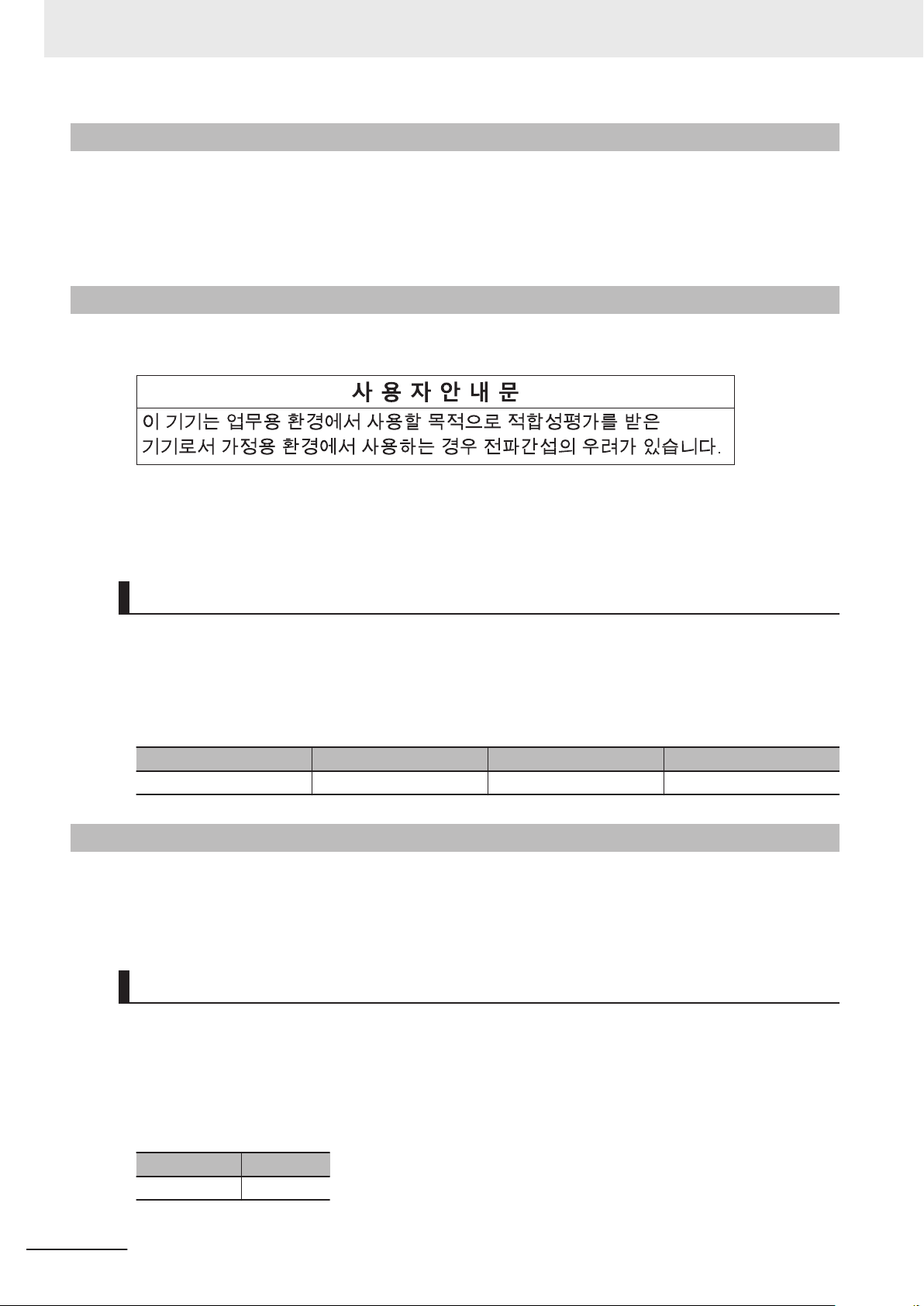
Regulations and Standards
Conformance to UL and CSA Standards
Some NX-series products comply with UL and CSA standards.
If you use a product that complies with UL or CSA standards and must apply those standards to your
machinery or devices, refer to the Instruction Sheet that is provided with the product. The Instruction
Sheet provides the application conditions for complying with the standards.
Conformance to KC Certification
When you use this product in South Korea, observe the following precautions.
This product meets the electromagnetic compatibility requirements for business use. There is a risk of
radio interference when this product is used in home.
Usage Conditions for KC Certification
Take the same measures as those described in Conformance to EU Directives on page 35
tion, attach a clamp core to the port side of the EtherNet/IP cable.
The recommended clamp core is given below
Recommended Clamp Core
Manufacturer Product Model Turns of cable
NEC TOKIN Clamp core ESD-SR-250 1 turn
.
Conformance to Shipbuilding Standards
This product complies with the following shipbuilding standards. Applicability to the shipbuilding stand-
ards is based on certain usage conditions. It may not be possible to use the product in some locations.
Contact your OMRON representative before attempting to use a Controller on a ship.
. In addi-
36
Usage Conditions for NK and LR Shipbuilding Standards
• This product must be installed within a control panel.
• Gaps in the door to the control panel must be completely filled or covered with gaskets or other ma-
terial.
•
The following noise filter must be connected to the power supply line.
Noise Filter
Manufacturer Model
Cosel Co., Ltd. TAH-06-683
NX-series NX102 CPU Unit Hardware User’s Manual (W593)
Page 39

Software Licenses and Copyrights
This product incorporates certain third party software. The license and copyright information associat-
ed with this software is available at http://www
Regulations and Standards
.fa.omron.co.jp/nj_info_e/.
NX-series NX102 CPU Unit Hardware User’s Manual (W593)
37
Page 40
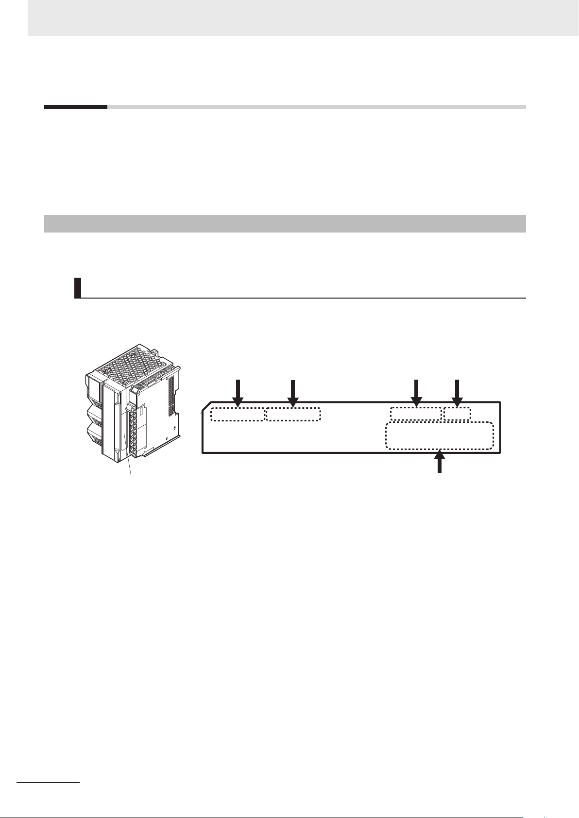
ID Information Indication
Unit version Hardware revision
Lot number
Serial number
MAC address
LOT No. DDMYY£ xxxx
PORT1
££££££££££££
PORT2
££££££££££££
Ver.£.££ HW Rev.£
Versions
Versions
Hardware revisions and unit versions are used to manage the hardware and software in NX-series
Units and EtherCAT slaves.
The hardware revision or unit version is updated each time there is a change in hardware or software
specifications. Even when two Units or EtherCAT slaves have the same model number, they will have
functional or performance differences if they have different hardware revisions or unit versions.
Checking Versions
You can check versions in the ID information indications on the product or with the Sysmac Studio.
Checking Unit Versions on ID Information Indications
The unit version is given on the ID information indication on the side of the product.
The ID information on an NX-series CPU Unit NX102-££££ is shown below.
Note The hardware revision is not displayed for the Unit that the hardware revision is in blank.
38
NX-series NX102 CPU Unit Hardware User’s Manual (W593)
Page 41
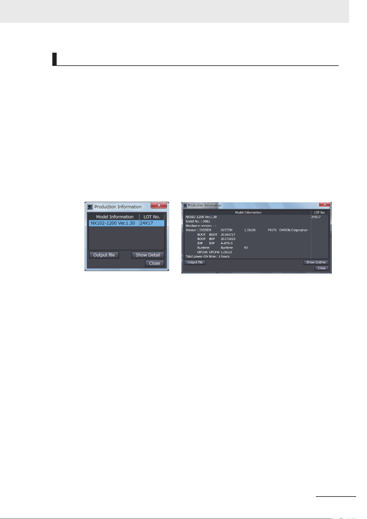
Versions
Checking Unit Versions with the Sysmac Studio
Checking the Unit Version of a Unit
l
You can use the Production Information while the Sysmac Studio is online to check the unit ver-
sion of a Unit. You can do this for the CPU Unit and NX Units on the CPU Rack.
Use the following procedure to check the unit version.
1 Right-click
view Explorer and select Display Production Information.
The Production Information Dialog Box is displayed.
2 Click the Show Detail or Show Outline
Information
The view will change between the Production information details and outline.
The information that is displayed is different for the Outline View and Detail View. The Detail
View displays the unit version, hardware version, and software versions. The Outline View dis-
plays only the unit version.
Note The hardware revision is separated by
ware revision is not displayed for the Unit that the hardware revision is in blank.
CPU Rack under Configurations and Setup - CPU/Expansion Racks in the Multi-
Button at the lower right of the Production
Dialog Box.
Outline View Detail View
"/" and displayed on the right of the hardware version. The hard-
Checking the Unit Version of an EtherCAT Slave
l
You can use the Production Information while the Sysmac Studio is online to check the unit ver-
sion of an EtherCAT slave. Use the following procedure to check the unit version.
1 Double-click EtherCAT
click EtherCAT under Configurations and Setup and select Edit from the menu.
The EtherCAT Tab Page is displayed for the Controller Configurations and Setup Layer.
under Configurations and Setup in the Multiview Explorer. Or, right-
2 Right-click the master on the EtherCAT Tab Page and select Display Production Information.
The Production Information Dialog Box is displayed. The unit version is displayed after "Rev
Changing Information Displayed in Production Information Dialog Box
l
1 Click the Show Detail or Show Outline Button at the lower right of the Production
Information Dialog Box.
NX-series NX102 CPU Unit Hardware User’s Manual (W593)
."
39
Page 42

Versions
The view will change between the Production information details and outline.
Outline View Detail View
Unit Versions of CPU Units and Sysmac Studio Versions
The functions that are supported depend on the unit version of the NX-series CPU Unit. The version of
Sysmac Studio that supports the functions that were added for an upgrade is also required to use
those functions.
Refer to A-4 V
CPU Units and the Sysmac Studio versions, and for the functions that are supported by each unit ver-
sion.
ersion Information on page A-7 for the relationship between the unit versions of the
40
NX-series NX102 CPU Unit Hardware User’s Manual (W593)
Page 43

Related Manuals
The following manuals are related. Use these manuals for reference.
Manual name Cat. No. Model numbers Application Description
NX-series
NX102 CPU Unit
Hardware
User’
s Manual
NJ/NX-series CPU Unit
Software User
NJ/NX-series Instructions
Reference Manual
NJ/NX-series CPU Unit
Motion Control User’
Manual
NJ/NX-series
Motion Control Instructions
Reference Manual
NJ/NX-series
CPU Unit
Built-in EtherCA
User
’s Manual
NJ/NX-series
CPU Unit
Built-in EtherNet/IP™ Port
s Manual
User’
NJ/NX-series
CPU Unit
OPC UA
s Manual
’
User
s Manual
’
s
T® Port
W593
W501
W502
W507
W508
W505
W506
W588
NX102-££££
NX701-££££
NX102-££££
NX1P2-££££
NJ501-££££
NJ301-££££
NJ101-££££
NX701-££££
NX102-££££
NX1P2-££££
NJ501-££££
NJ301-££££
NJ101-££££
NX701-££££
NX102-££££
NX1P2-££££
NJ501-££££
NJ301-££££
NJ101-££££
NX701-££££
NX102-££££
NX1P2-££££
NJ501-££££
NJ301-££££
NJ101-££££
NX701-££££
NX102-££££
NX1P2-££££
NJ501-££££
NJ301-££££
NJ101-££££
NX701-££££
NX102-££££
NX1P2-££££
NJ501-££££
NJ301-££££
NJ101-££££
NX102-££££
NJ501-1£00
Learning the basic
specifications of the
NX102 CPU Units,
including introductory
information, designing, installation, and
maintenance.
Mainly hardware information is provided.
Learning how to program and set up an
NJ/NX-series CPU
Unit.
Mainly software information is provided.
Learning detailed
specifications on the
basic instructions of
an NJ/NX-series
CPU Unit.
Learning about motion control settings
and programming
concepts.
Learning about the
specifications of the
motion control instructions.
Using the built-in
EtherCA
NJ/NX-series CPU
Unit.
Using the built-in
EtherNet/IP port on
an NJ/NX-series
CPU Unit.
Using the OPC UA. Describes the OPC UA.
T port on an
An introduction to the entire NX102
system is provided along with the following information on the CPU Unit.
• Features and system configura-
tion
• Introduction
• Part names and functions
• General specifications
• Installation and wiring
• Maintenance and inspection
The following information is provided
on a Controller built with an NJ/NXseries CPU Unit.
• CPU Unit operation
• CPU Unit features
• Initial settings
• Programming based on IEC
61131-3 language specifications
The instructions in the instruction set
(IEC 61
scribed.
The settings and operation of the
CPU Unit and programming concepts for motion control are described.
The motion control instructions are
described.
Information on the built-in EtherCAT
port is provided.
This manual provides an introduction
and provides information on the configuration, features, and setup.
Information on the built-in
EtherNet/IP port is provided.
Information is provided on the basic
setup, tag data links, and other features.
Related Manuals
131-3 specifications) are de-
NX-series NX102 CPU Unit Hardware User’s Manual (W593)
41
Page 44

Related Manuals
Manual name Cat. No. Model numbers Application Description
NX-series
CPU Unit
FINS Function
’
s Manual
User
NJ/NX-series
Database Connection CPU
Units
s Manual
User’
NJ/NX-series
roubleshooting Manual
T
Sysmac Studio Version 1
Operation Manual
NX-series
T® Coupler Unit
EtherCA
User
’s Manual
NX-series
Data Reference Manual
NX-series
NX Units
s Manual
User’
NX-series
Safety Control Unit
User's Manual
W596
W527
W503
W504 SYSMAC
W519
W525
W521
W522
W592
W566
W523
W524
W540
W565
W567
Z930
NX701-££20
NX102-££££
NX701-££20
NX102-££20
NJ501-££20
NJ101-££20
NX701-££££
NX102-££££
NX1P2NJ501-££££
NJ301-££££
NJ101-££££
-SE2£££
NX-ECC£££
NX-££££££
NX-ID££££
NX-IA££££
NX-OC££££
NX-OD££££
NX-MD££££
NX-AD££££
NX-DA££££
NX-HAD£££
NX-TS££££
NX-HB££££
NX-PD1£££
NX-PF0£££
NX-PC0£££
NX-TBX01
NX-EC0£££
NX-ECS£££
NX-PG0£££
NX-CIF£££
NX-RS££££
NX-ILM£££
NX-SL££££
NX-SI££££
NX-SO££££
££££
Using the FINS function of an NX-series
CPU Unit.
Using the database
connection service
with NJ/NX-series
Controllers.
Learning about the
errors that may be
detected in an
NJ/NX-series Con-
.
troller
Learning about the
operating procedures
and functions of the
Sysmac Studio.
Learning how to use
the NX-series EtherCAT Coupler Unit
and EtherCAT Slave
Terminals.
Referencing lists of
the data that is required to configure
systems with NX-series Units.
Learning how to use
NX Units.
Learning how to use
NX-series Safety
Control Units.
Describes the FINS function of an
NX-series CPU Unit.
Describes the database connection
service.
Concepts on managing errors that
may be detected in an NJ/NX-series
Controller and information on individual errors are described.
Describes the operating procedures
of the Sysmac Studio.
The following items are described:
the overall system and configuration
methods of an EtherCAT Slave Terminal (which consists of an NX-series EtherCAT Coupler Unit and NX
Units), and information on hardware,
setup, and functions to set up, control, and monitor NX Units through
EtherCAT.
Lists of the power consumptions,
weights, and other NX Unit data that
is required to configure systems with
NX-series Units are provided.
Describes the hardware, setup methods, and functions of the NX Units.
Manuals are available for the following Units.
Digital I/O Units, Analog I/O Units,
System Units, Position Interface
Units, Communications Interface
Units, Load Cell Input Unit, and IOLink Master Units.
Describes the hardware, setup methods, and functions of the NX-series
Safety Control Units.
42
NX-series NX102 CPU Unit Hardware User’s Manual (W593)
Page 45

Manual name Cat. No. Model numbers Application Description
NA-series Programmable
erminal
T
Software User
NS-series Programmable
Terminals
Programming Manual
’s Manual
V118
V073
NA5-£W££££
£££££
NS15NS12-£££££
NS10-£££££
NS8-£££££
NS5-£££££
Learning about NAseries PT pages and
object functions.
Learning how to use
the NS-series Programmable T
nals.
ermi-
Describes the pages and object
functions of the NA-series Programmable Terminals.
Describes the setup methods, functions, etc. of the NS-series Programmable Terminals.
Related Manuals
NX-series NX102 CPU Unit Hardware User’s Manual (W593)
43
Page 46

Terminology
Terminology
Term Description
AT One of the attributes of a variable.
This attribute allows the user to specify what is assigned to a variable. An I/O
port or an address in memory used for CJ-series Units can be specified.
CJ-series Unit Any of the CJ-series Units that can be used with an NJ-series Controller.
memory used for CJ-series Units One type of I/O memory that contains addresses to which variables can be as-
signed, for example, when accessing a CJ-series Unit or CJ-series network. It
can be accessed only with variables with an A
CPU Unit The Unit that serves as the center of control for a Machine Automation Control-
ler. The CPU Unit executes tasks, refreshes I/O for other Units and slaves, etc.
The NJ/NX-series CPU Units include the NX701-££££, NX102NX1P2-££££, NJ501-££££.
EtherCAT Master Function Module One of the function modules. This function module controls the EtherCAT slaves
as the EtherCA
EtherNet/IP Function Module One of the function modules. This function module controls the built-in
EtherNet/IP port.
FB An acronym for "function block."
FUN An abbreviation for "function."
I/O port A logical interface that is used by the CPU Unit to exchange data with an exter-
nal device (slave or Unit).
I/O map settings Settings that assign variables to I/O ports. Assignment information between I/O
ports and variables.
I/O refreshing Cyclic data exchange with external devices that is performed with predetermined
memory addresses.
MC Test Run A function to check motor operation and wiring from the Sysmac Studio.
NX bus The NX-series internal bus. NX102 and NX1P2 CPU Units have the NX bus.
NX Units Any of the NX-series Units that perform I/O processing with connected external
devices. The Communications Coupler Units are not included with the NX Units.
PDO communications An abbreviation for process data communications. Data is exchanged between
the master and slaves on a process data communications cycle. (The process
data communications cycle is the same as the task period of the primary periodic
task.)
PLC Function Module One of the function modules. This function module executes the user program,
sends commands to the Motion Control Function Module, and provides an interface to the USB and SD Memory Card.
POU An acronym for "program organization unit". A POU is a unit in a program execu-
tion model that is defined in IEC 61
A POU contains an algorithm and a local variable table and forms the basic unit
used to build a user program.
There are three types of POUs: programs, functions, and function blocks.
SDO communications One type of EtherCA
used to transmit information whenever required.
Sysmac Studio A computer software application for setting, programming, debugging, and trou-
bleshooting NJ/NX-series Controllers. It also provides operations for motion control and a Simulator.
upload T
o transfer data from the Controller to the Sysmac Studio with the synchroniza-
tion operation of the Sysmac Studio.
T master
.
131-3.
T communications in which service data objects (SDOs) are
T attribute.
££££,
44
NX-series NX102 CPU Unit Hardware User’s Manual (W593)
Page 47

Terminology
Term Description
information One of the event levels for Controller events or user-defined events. These are
not errors, but appear in the event log to notify the user of specific information.
Event Setup Settings that define user-defined errors and user-defined information.
event task A task that executes a user program only once when the task execution condi-
tions are met.
event log A function that recognizes and records errors and other events.
inline ST ST programming that is included within a ladder diagram.
edge One of the attributes of a variable.
This attribute makes a BOOL variable pass TRUE to a function block when the
variable changes from F
ALSE.
F
cam data variable A variable that represents the cam data as a structure array.
A cam data variable is an array structure that consists of phases and displacements.
observation One of the event levels for Controller events or user-defined events.
These are minor errors that do not affect control operations, but appear in the
event log to notify the user of specific information.
function module One of the functional units of the software configuration of the CPU Unit.
basic data type Any of the data types that are defined by IEC 61
They include Boolean, bit string, integer, real, duration, date, time of day
and time, and text string data types.
"Basic data type" is used as opposed to derivative data types, which are defined
by the user.
forced refreshing Forcing the refreshing of an input from an external device or an output to an ex-
ternal device, e.g., when the user debugs a program.
Addresses that are subject to forced refreshing can still be overwritten from the
user program.
union One of the derivative data types. It allows you to handle the same data as differ-
ent data types.
global variable A variable that can be read or written from all POUs (programs, functions, and
function blocks).
minor fault level Controller error An error for which some of the control operations for one of the function modules
in the NJ/NX-series Controller stop.
An NJ/NX-series CPU Unit continues operation even after a minor fault level
Controller error occurs.
Special Unit Setup A generic term for the settings for a Special Unit, including the settings in allocat-
ed DM Area words.
structure One of the derivative data types. It consists of multiple data types placed togeth-
er into a layered structure.
Constant One of the attributes of a variable.
If you specify the Constant attribute for a variable, the value of the variable cannot be written by any instructions, ST operators, or CIP message communications.
Controller The range of devices that are directly controlled by the CPU Unit.
In the NX-series System, the Controller includes the CPU Rack and EtherCA
slaves (including general-purpose slaves and Servo Drives).
In the NJ-series System, the Controller includes the CPU Rack, Expansion
Racks, and EtherCA
Drives).
ALSE to TRUE or when it changes from TRUE to
131-3.
, date
T
T slaves (including general-purpose slaves and Servo
NX-series NX102 CPU Unit Hardware User’s Manual (W593)
45
Page 48

Terminology
Term Description
Controller error Errors that are defined by the NJ/NX-series System.
“Controller error” is a collective term for major fault level, partial fault level, minor
fault level, and observation Controller events.
Controller event One of the events in the NJ/NX-series System. Controller events are errors and
information that are defined by the system for user notification. A Controller
event occurs when the system detects a factor that is defined as a Controller
event.
Controller information Information that is defined by the NJ/NX-series System that is not an error. It rep-
resents an information Controller event.
Servo Drive/encoder input slave Any of the EtherCAT slaves that is assigned to an axis. In the NJ/NX-series Sys-
tem, it would be a Servo Drive or Encoder Input Slave Unit.
axis A functional unit within the Motion Control Function Module. An axis is assigned
to the drive mechanism in an external Servo Drive or the sensing mechanism in
an external Encoder Input Slave Unit.
axes group A functional unit that groups together axes within the Motion Control Function
Module.
Axes Group Variable A system-defined variable that is defined as a structure and provides status in-
formation and some of the axes parameters for an individual axes group.
An Axes Group V
structions and to monitor the command interpolation velocity
and other information for the axes group.
Axis Variable A system-defined variable that is defined as a structure and provides status in-
formation and some of the axis parameters for an individual axis.
An Axis Variable is used to specify an axis for motion control instructions and to
monitor the command position, error information, and other information for the
axis.
system common processing System processing that is performed by the CPU Unit to perform I/O refreshing
and the user program execution within a task. Exclusive control of variables between tasks, data trace processing, and other processing is performed.
system service Processing that is performed by the CPU Unit in unused time between task proc-
essing. The system service includes communications processing, SD Memory
Card access processing, self-diagnosis processing, and other processing.
system-defined variable A variable for which all attributes are defined by the system and cannot be
changed by the user
Initial V
alue One of the attributes of a variable. The variable is set to the initial value in the
following situations.
• When power is turned ON
• When the CPU Unit changes to RUN mode
• When you specify to initialize the values when the user program is transferred
• When a major fault level Controller error occurs
slave A device that performs remote I/O for a master.
Slave Terminal A building-block remote I/O terminal to which a Communications Coupler Unit
and NX Units are mounted. A Slave Terminal is one type of slave.
slave and Unit configurations A generic term for the EtherCA
absolute encoder home offset This data is used to restore in the CPU Unit the actual position of a Servo Drive
with an absolute encoder. The of
sition after homing and the absolute data that is read from the absolute encoder.
project unit version A unit version to be set for the project. It is set for the project in the Select Device
Area of the Project Properties Dialog Box on the Sysmac Studio.
ariable is used to specify an axes group for motion control in-
, error information,
.
T configuration and Unit configuration.
fset is the difference between the command po-
46
NX-series NX102 CPU Unit Hardware User’s Manual (W593)
Page 49

Terminology
Term Description
major fault level Controller error An error for which all NJ/NX-series Controller control operations stop. The CPU
Unit immediately stops user program execution and turns OFF the loads for all
slaves and Units (including remote I/O).
download To transfer data from the Sysmac Studio to the Controller with the synchroniza-
tion operation of the Sysmac Studio.
task An attribute that defines when a program is executed.
task period The interval at which the primary periodic task or a periodic task is executed.
Communications Coupler Unit The generic name of an interface unit for remote I/O communications on a net-
work between NX Units and a host network master
Coupler Unit is a Communications Coupler Unit for an EtherCAT network.
periodic task A tasks for which user program execution and I/O refreshing are performed each
period.
device A general term for any Unit or slave that is refreshed by the I/O refreshing that is
performed by the CPU Unit. Specifically, it refers to EtherCA
on the CPU Unit, built-in I/O, Option Boards, and CJ-series Units.
device output An output for any Unit or slave that is refreshed by the I/O refreshing that is per-
formed by the CPU Unit.
device variable A variable that is used to access a specific device through an I/O port.
synchronization A function that automatically compares the information in the NJ/NX-series Con-
troller with the information in the Sysmac Studio, displays any dif
cations in a hierarchical form, and can be used to synchronize the information.
namespace A system that is used to group and nest the names of functions, function block
definitions, and data types.
Network Publish One of the attributes of a variable.
This attribute allows you to use CIP message communications or tag data links
to read/write variables from another Controller or from a host computer.
array specification One of the variable specifications. An array variable contains multiple elements
of the same data type. The elements in the array are specified by serial numbers
called subscripts that start from the beginning of the array.
derivative data type A data type that is defined by the user
derivative data types.
Range Specification One of the variable specifications. You can specify a range for a variable in ad-
vance. The variable can take only values that are in the specified range.
general-purpose slave Any of the EtherCAT slaves that cannot be assigned to an axis.
function A POU that is used to create an object that determines a unique output for the
same input, such as for data processing.
function block A POU that is used to create an object that can have a different output for the
same input, such as for a timer or counter
partial fault level Controller error
primary periodic task The task with the highest priority
program Along with functions and function blocks, one of the three types of POUs.
process data communications One type of EtherCAT communications in which process data objects (PDOs)
An error for which all of the control operations for one of the function modules in
the NJ/NX-series Controller stop.
An NJ/NX-series CPU Unit continues operation even after a partial fault level
Controller error.
Programs are assigned to tasks to execute them.
are used to exchange information cyclically and in realtime. Process data communications are also called PDO communications.
. Structures, unions, and enumerations are
.
.
. For example, an EtherCA
T slaves, NX Units
ferences and lo-
T
NX-series NX102 CPU Unit Hardware User’s Manual (W593)
47
Page 50

Terminology
Term Description
variable A representation of data, such as a numeric value or character string, that is
used in a user program.
You can change the value of a variable by assigned the required value. “Variable” is used as opposed to “constant,” for which the value does not change.
variable memory A memory area that contains the present values of variables that do not have AT
specifications. It can be accessed only with variables without an AT attribute.
Retain One of the attributes of a variable. The values of variables with a Retain attribute
are held at the following times. (Variables without a Retain attribute are set to
their initial values.)
• When power is turned ON after a power interruption
• When the CPU Unit changes to RUN mode
• When you specify to not initialize the values when the user program is trans-
ferred
instruction The smallest unit of the processing elements that are provided by OMRON for
use in POU algorithms.
There are ladder diagram instructions (program inputs and outputs), function instructions, function block instructions, and ST statements.
main memory The memory inside the CPU Unit that is used by the CPU Unit to execute the OS
and user program.
Motion Control Function Module
motion control instruction A function block instruction that executes motion control.
user-defined event One of the events in the NJ/NX-series System. These events are defined by the
user-defined variable A variable for which all of the attributes are defined by the user and can be
user program All of the programs in one project.
Unit A device that mounts to the CPU Rack or an Expansion Rack.
Unit configuration The configuration information for the Units that are set on the Sysmac Studio.
literal A constant expression that is used in a user program.
enumeration One of the derivative data types. This data type takes one item from a prepared
enumerator One of the values that an enumeration can take expressed as a character string.
local variable A variable that can be accessed only from inside the POU in which it is defined.
One of the function modules. The MC Function Module performs motion control
based on commands from the motion control instructions that are executed in
the user program.
The Motion Control Function Module supports instructions that are based on
function blocks for PLCopen® motion control as well as instructions developed
specifically for the Motion Control Function Module.
user. “User-defined events” is a generic term for user-defined errors and userdefined information.
changed by the user.
This information tells what Unit models are connected to the CPU Unit and
where they are connected.
name list of enumerators as its value.
The value of an enumeration is one of the enumerators.
“Local variable” is used as opposed to “global variable.”
Local variables include internal variables, input variables, output variables, in-out
variables, and external variables.
48
NX-series NX102 CPU Unit Hardware User’s Manual (W593)
Page 51
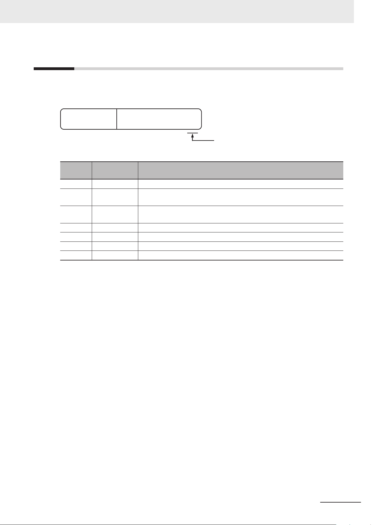
Revision History
W593-E1-07
Revision code
Cat. No.
A manual revision code appears as a suffix to the catalog number on the front and back covers of the
manual.
Revision History
Revision
code
01 April 2018 Original production
02 July 2018 Made changes accompanying release of unit version 1.31 of the CPU Unit.
03 April 2019
04 July 2019
05 July 2019 Corrected mistakes.
06 August 2019 Corrected mistakes.
07 October 2020 Corrected mistakes.
Date Revised content
Corrected mistakes.
• Made changes accompanying release of unit version 1.32 of the CPU Unit.
• Added Shipbuilding Standards (NK and LR).
Made changes accompanying release of unit version 1.40 of the NX102-££00.
NX-series NX102 CPU Unit Hardware User’s Manual (W593)
49
Page 52

Revision History
50
NX-series NX102 CPU Unit Hardware User’s Manual (W593)
Page 53

1
Introduction to NX-series Controllers
This section describes the features, basic system configuration, specifications, and
overall operating procedure of an NX-series Controller
1-1 The NX-series Controller ...............................................................................1-2
1-1-1 Features .......................................................................................................... 1-3
1-1-2 Introduction to the System Configurations ...................................................... 1-6
1-2 Specifications ................................................................................................. 1-9
1-3 Overall Operating Procedure for the CPU Unit ......................................... 1-15
1-3-1 Overall Procedure ......................................................................................... 1-15
1-3-2 Procedure Details .......................................................................................... 1-16
NX102.
1
NX-series NX102 CPU Unit Hardware User’s Manual (W593)
1-1
Page 54
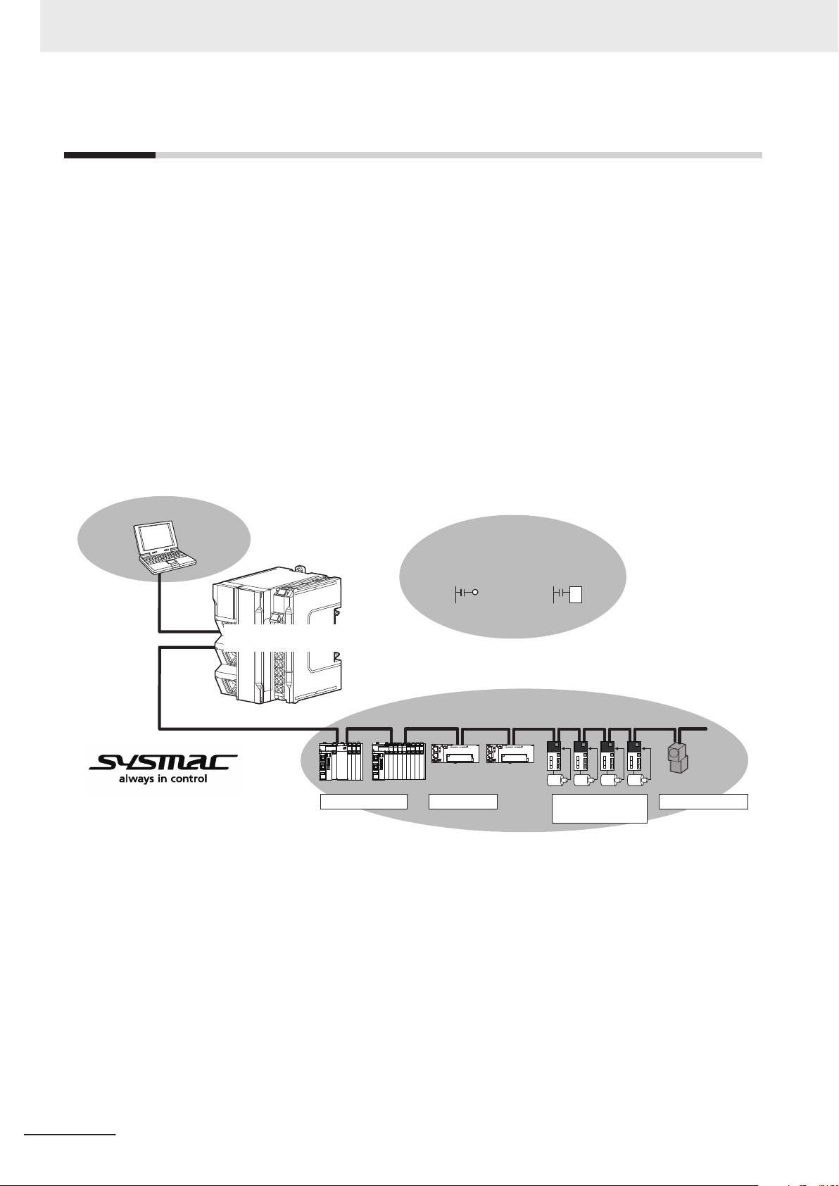
Sysmac Studio
Automation Software
Multitasking, Synchronized Control
Sequence control
Motion control
IEC Programming
EtherCAT control network
Safety devices I/O controls
Servo Drives and
Inverters
Machine vision
NX-series
NX102 Controller
1 Introduction to NX-series Controllers
1-1
The NX-series Controller
The SYSMAC NX-series are next-generation machine automation controllers that provide the function-
ality and high-speed performance that are required for machine control. They provide the safety, relia-
bility, and maintainability that are required of industrial controllers.
The NX-series Controllers provide the functionality of previous OMRON PLCs, and they also provide
the functionality that is required for motion control. Synchronized control of I/O devices on high-speed
EtherCAT can be applied to safety devices, vision systems, motion equipment, discrete I/O, and more.
Especially, the NX-series NX102 Controller can perform I/O operation with a mounted NX Unit.
OMRON offers the new Sysmac Series of control devices designed with unified communications spec-
ifications and user interface specifications. The NX-series Machine Automation Controllers are part of
the Sysmac Series. You can use them together with EtherCAT slaves, other Sysmac products, and the
Sysmac Studio Automation Software to achieve optimum functionality and ease of operation.
With a system that is created from Sysmac products, you can connect components and commission
the system through unified concepts and usability.
1-2
NX-series NX102 CPU Unit Hardware User’s Manual (W593)
Page 55

1 Introduction to NX-series Controllers
1-1 The NX-series Controller
1-1-1
Features
Hardware Features
Standard-feature EtherCAT Control Network Support
l
All CPU Units provide an EtherCAT master port for EtherCAT communications.
EtherCAT is an advanced industrial network system that achieves faster
cations. It is based on Ethernet. Each node achieves a short fixed communications cycle time by
transmitting Ethernet frames at high speed.
The standard-feature EtherCAT control network allows you to connect all of the devices required
for machine control (e.g., I/O systems, Servo Drives, Inverters, and machine vision) to the same
network.
Support for EtherCAT Slave Terminals
l
You can use EtherCAT Slave Terminals to save space. You can also flexibly build systems with the
wide variety of NX Units.
Achieving a Safety Subsystem
l
You can use NX-series Safety Control Units to integrate safety controls in sequence and motion
control systems.
, more-efficient communi-
1
1-1-1 Features
Standard-feature EtherNet/IP Communications Ports
l
All CPU Units provide two EtherNet/IP ports for EtherNet/IP communications.
EtherNet/IP is a multi-vendor industrial network that uses Ethernet. You can use it for networks be-
tween Controllers or as a field network. The use of standard Ethernet technology allows you to con-
nect to many different types of general-purpose Ethernet devices. Moreover, with two EtherNet/IP
ports these CPU Units enable the integrated control of two separate control systems, for example,
one of the host information control system for communications between Controllers and the other
for a lower-level field network control system.
NX-series Units Connectable
l
The CPU Unit can be connected with up to 32 NX Units including NX-series Digital I/O Units, Ana-
log I/O Units, and other I/O Units.
Battery-free Operation
l
The following data (other than the clock data) is retained in the built-in non-volatile memory.
• User program
• Set values
• Variables retained during power interruption
• Event logs
The retention period for the clock data is limited*1.
When the clock data is not needed or the equipment’s power OFF time is shorter than the clock
data retention period, the battery-free operation is possible and man-hours for battery replacement
can be reduced.
If you turn OFF the power supply to the equipment for a longer period of time than the clock data
retention period, mount a battery which is sold separately.
NX-series NX102 CPU Unit Hardware User’s Manual (W593)
1-3
Page 56

1 Introduction to NX-series Controllers
*1. Approximately 10 days at an ambient temperature of 40°C. Refer to 3-1-5 Battery on page 3-12 for detail.
Standard-feature SD Memory Card Slot
l
Y
ou can access an SD Memory Card that is mounted in the CPU Unit from the user program.
Highly Reliable Hardware
l
The NX-series Controllers provide the hardware reliability and RAS functions that you expect of a
PLC.
Software Features
Integrated Sequence Control and Motion Control
l
An NX-series CPU Unit can perform both sequence control and motion control. You can simultane-
ously achieve both sequence control and multi-axes synchronized control. Sequence control, mo-
tion control, and I/O refreshing are all executed in the same control period.
The same control period is also used for the process data communications cycle for EtherCAT
enables precise sequence and motion control in a fixed period with very little deviation.
. This
Programming Languages Based on the IEC 61131-3 International Standard
l
The NJ-series Controllers support language specifications that are based on IEC 61131-3. To
these, OMRON has added our own improvements. Motion control instructions that are based on
PLCopen® standards and an instruction set (POUs) that follows IEC rules are provided.
Programming with Variables to Eliminate Worrying about the Memory Map
l
You access all data through variables in the same way as for the advanced programming languag-
es that are used on computers. Memory in the CPU Unit is automatically assigned to the variables
that you create so that you do not have to remember the physical addresses.
A Wealth of Security Features
l
The many security features of the NX-series Controllers include operation authority settings and re-
striction of program execution with IDs.
Complete Controller Monitoring
l
The CPU Unit monitors events in all parts of the Controller, including mounted NX Units and Ether-
CAT slaves.
T
roubleshooting information for errors is displayed on the Sysmac Studio or on an NS-series PT.
Events are also recorded in logs.
1-4
Sysmac Studio Automation Software
l
The Sysmac Studio provides an integrated development environment that covers not only the Con-
troller, but also covers peripheral devices and devices on EtherCAT. You can use consistent proce-
dures for all devices regardless of the differences in the devices. The Sysmac Studio supports all
phases of Controller application, from designing through debugging, simulations, commissioning,
and changes during operation.
NX-series NX102 CPU Unit Hardware User’s Manual (W593)
Page 57

1 Introduction to NX-series Controllers
A Wealth of Simulation Features
l
The many simulation features include execution, debugging, and task execution time estimates on
a virtual controller.
1-1 The NX-series Controller
1
1-1-1 Features
NX-series NX102 CPU Unit Hardware User’s Manual (W593)
1-5
Page 58

EtherNet/IP
LAN
Slave Terminal
Servo Drives/
Encoder input slaves
General-purpose
slaves
Support Software
EtherCAT
CPU Rack
NX Units
EtherCA
T Network
configuration
Built-in EtherNet/IP port 1
Built-in EtherNet/IP port 2
Built-in EtherCAT port
NX Unit configuration
NX-series
NX102 CPU Unit
1 Introduction to NX-series Controllers
1-1-2
Introduction to the System Configurations
The NX-series Controller NX102 supports the following system configurations.
Basic System Configurations
The NX-series Controller NX102 basic configurations include the EtherCAT network configuration, NX
Unit configuration, and the Support Software.
• EtherCA
You can use the built-in EtherCAT port to connect to EtherCAT Slave Terminals, to general-purpose
slaves for analog and digital I/O, and to Servo Drives and encoder input slaves. An EtherCAT net-
work configuration enables precise sequence and motion control in a fixed cycle with very little devi-
ation.
• NX Unit configuration
The CPU Unit can be connected with up to 32 NX Units (NX-££££££) including NX-series Digi-
tal I/O Units, Analog I/O Units, and other I/O Units. These NX Units can be flexibly combined with
the CPU Unit and configure a CPU Rack to support various applications.
• Support Software
You can connect the Support Software through an Ethernet cable that is connected to the built-in
EtherNet/IP port 1 or 2 in the CPU Unit.
Refer to 3-5-2 Connection on page 3-18 for details on the connection configuration of the Support
Software.
T Network Configuration
1-6
NX-series NX102 CPU Unit Hardware User’s Manual (W593)
Page 59
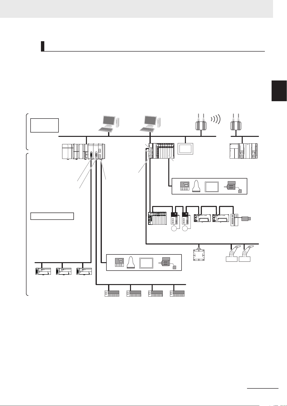
EtherCAT
Slave Terminal
Vision Systems
Sysmac
Studio
EtherNet/IP
DeviceNet
EtherCAT
CompoNet
REMOTE TERMINAL
01 2 3 4 5 6 7 8 9 10 11 12 13 14 15
OUT
CRT1-OD16
MS NS
WORD NODE ADR
REMOTE TERMINAL
01 2 3 4 5 6 7 8 9 10 11 12 13 14 15
OUT
CRT1-OD16
MS NS
WORD NODE ADR
REMOTE TERMINAL
01 2 3 4 5 6 7 8 9 10 11 12 13 14 15
OUT
CRT1-OD16
MS NS
WORD NODE ADR
EtherNet/IP
Information
Level
Built-in EtherNet/IP port 1
Built-in EtherNet/IP port 2
Built-in
EtherCAT port
Built-in EtherNet/IP ports
CompoNet Master Unit
CompoNet slaves
DeviceNet slaves
DeviceNet Unit
NJ-series
CPU Unit
Field Level
NX-series
NX102
CPU Unit
Serial
Communications
Unit
RS-232C,
RS-422A/485
RFID system Robots
Servo Drives
General-purpose
slaves
Serial communications devices
NX-series Communications
Interface Unit
General-purpose components or OMRON components
Serial communications devices
General-purpose components or OMRON components
NJ/NX-series
CPU Unit
Programmable
terminal
FA Wireless
LAN Unit
FA
Communications
Software
1 Introduction to NX-series Controllers
Network Configurations
• Host computers, HMIs, and other NJ/NX-series Controllers or field network devices are connected
to the two built-in EtherNet/IP ports.
• A DeviceNet network is connected to a CJ-series DeviceNet Unit mounted to the NJ-series CPU
Unit.
•
A serial communications network is connected to the following Units.
NX-series Communications Interface Unit
CJ-series Serial Communications Unit
1-1 The NX-series Controller
1
1-1-2 Introduction to the System Configurations
Refer to the NJ/NX-series CPU Unit Software User’
work configuration.
s Manual (Cat. No. W501) for details on the net-
NX-series NX102 CPU Unit Hardware User’s Manual (W593)
1-7
Page 60

1 Introduction to NX-series Controllers
Support Software
You can use the following Support Software to set up, monitor, and debug an NX-series Controller.
• Sysmac Studio
The Sysmac Studio is the main Support Software that you use for an NX-series Controller
you can set up the Controller configurations, parameters, and programs, and you can debug and
simulate operation.
• Other Support Software
The following Support Software is also included in the Sysmac Studio Software Package Standard
Edition.
Configuration software Application
Sysmac Studio The Sysmac Studio is used for sequence control, motion control, and all other operations
except those described below
Network Configurator
CX-Integrator The CX-Integrator is used for remote I/O communications with a CJ-series DeviceNet Unit
CX-Protocol The CX-Protocol is used for protocol macros with the CJ-series Serial Communications
CX-Designer The CX-Designer is used to create screens for NS-series PT
*1. If the NJ/NX-series Controller is a target device, you may also use Sysmac Studio version 1.10 or higher. Use the Network
Configurator if a CS/CJ-series PLC operates as the originator device.
The Network Configurator is used for tag data links on EtherNet/IP ports.
or CJ-series CompoNet Master Unit.
Units.
. On it,
.
*1
s.
1-8
NX-series NX102 CPU Unit Hardware User’s Manual (W593)
Page 61

1 Introduction to NX-series Controllers
1-2
Specifications
This section gives the specifications of the NX-series NX102 CPU Units.
Processing
time
Programming
Item
Instruction
execution
times
Program ca-
*1
pacity
Memory capacity for
variables
Data types Number of data types 1,000
Memory for
CJ-series
Units (Can
be specified
T
with A
specifications for variables.)
LD instruction 3.3 ns
Math instructions (for
long real data)
Size 5 MB
Number of
POU definitions
Number of
POU instances
Size 1.5 MB
Number of
variables
Size 32 MB
Number of
variables
*2
Quantity
Retain attribute
No Retain
attribute
CIO Area
W
ork Area
Holding Area
DM Area
EM Area
12££ 11££ 10££ 90££
70 ns or more
3,000
9,000
10,000
90,000
0 to 6,144 words
(CIO 0 to CIO 6,143)
0 to 512 words
(W0 to W51
0 to 1,536 words
(H0 to H1,535)
0 to 32,768 words
(D0 to D32,767)
32,768 words × 25 banks
(E0_0 to E18_32,767)
1)
*3
*3
*4
*4
*4*5
1-2 Specifications
NX102-
1
NX-series NX102 CPU Unit Hardware User’s Manual (W593)
1-9
Page 62
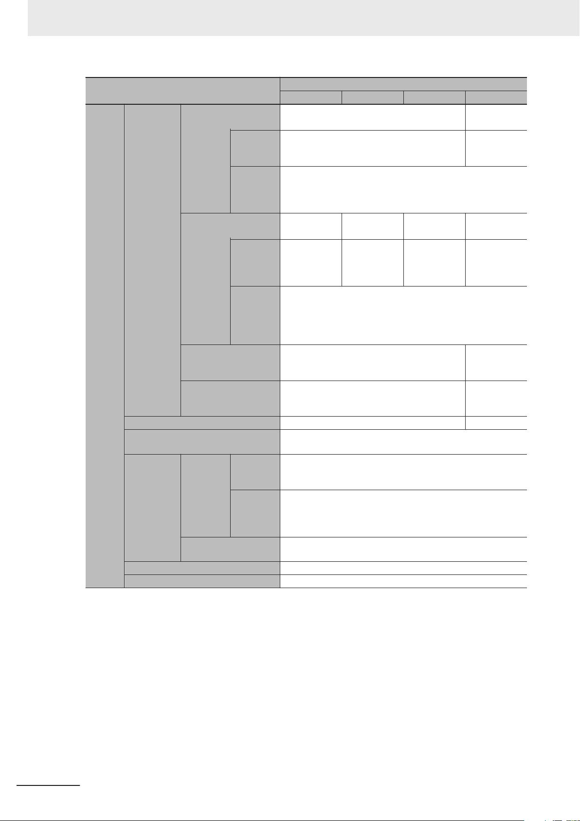
1 Introduction to NX-series Controllers
Motion
control
T
.
NX102-
Item
Maximum number of
controlled axes
Motion
control axes
Single-axis
position
control axes
Maximum number of
used real axes
Number of
controlled
*6
axes
Maximum number of axes for linear interpolation axis control
Number of axes for circular interpolation axis
control
Maximum number of axes groups 8 axes groups ---
Motion control period
Number of
cam data
Cams
Position units Pulse, mm, μm, nm, degree, and inch
Override factors 0.00%, or 0.01% to 500.00%
points
Maximum number of
cam tables
Used motion control servo
axes
Used single-axis
position
control
servo axes
Maximum
points per
cam table
Maximum
points for
all cam tables
12££ 11££ 10££ 90££
15 axes 4 axes
11 axes ---
4 axes
12 axes 8 axes 6 axes 4 axes
8 axes 4 axes 2 axes ---
4 axes
4 axes per axes group ---
2 axes per axes group ---
The same control period as that is used for the process data communications cycle for EtherCA
65,535 points
262,140 points
160 tables
1-10
NX-series NX102 CPU Unit Hardware User’s Manual (W593)
Page 63

1 Introduction to NX-series Controllers
Built-in
EtherNet/IP
port
Item
Number of ports 2
Physical layer 10BASE-T/100BASE-TX
Frame length 1,514 bytes max.
Media access method CSMA/CD
Modulation Baseband
Topology Star
Baud rate 100 Mbps (100BASE-TX)
Transmission media
Maximum transmission distance between Ethernet switch and node
Maximum number of cascade connections
Maximum number of
connections
*7
*1
Maximum
number of
clients that
can communicate
at one time
Maximum
number of
servers
that can
communicate at one
time
CIP service:
ag data
T
links (cyclic
communications)
CIP message service: Explicit
messages
Packet interval
Permissible communications band
Maximum number of tag
sets
T
ag types
Number of tags per connection (i.e., 1 tag set)
Maximum number of
tags
Maximum link data size
per node (total size for
all tags)
Maximum data size per
connection
Maximum number of
registrable tag sets
Maximum tag set size
Multi-cast packet filter
Class 3 (number of connections)
UCMM
(non-connection
type)
12££ 11££ 10££ 90££
STP (shielded, twisted-pair) cable of Ethernet category 5, 5e or higher
100 m
There are no restrictions if an Ethernet switch is used.
32 per port
64 total
Can be set for each connection.
1 to 10,000 ms in 1-ms increments
*8*9
12,000 pps
32 per port
40 total
Network variables
CIO/WR/HR/DM
8 (7 tags if Controller status is included in the tag set.)
256 per port
512 total
19,200 bytes per port
38,400 bytes total
600 bytes
32 per port
40 total
(1 connection = 1 tag set)
600 bytes (Two bytes are used if Controller status is included in the
tag set.)
1
Supported.
32 per port
64 total
(clients plus server)
32 per port
64 total
32 per port
64 total
(including heartbeat, CIP Safety routing)
*10
*10
NX102-
1-2 Specifications
1
NX-series NX102 CPU Unit Hardware User’s Manual (W593)
1-11
Page 64

1 Introduction to NX-series Controllers
Built-in
EtherNet/IP
port
Item
Maximum number of
routable CIP Safety con-
CIP Safety
routing
Number of TCP sockets 60
nections
Maximum routable safety data length per connection
Support profile/Model
Default Endpoint/Port opc.tcp://192.168.250.1:4840/
Maximum number of
sessions (Client)
Maximum number of
Monitored Items per
server
Sampling rate of Monitored Items (ms)
Maximum number of
Subscriptions per server
Maximum number of
variables to open
Maximum number of
alue attribute of varia-
V
bles to open
Structure’
able to open
s definitions
16 total
32 bytes
UA 1.02 Micro Embedded Device Server Profile
PLCOpen Information Model
5
2,000
0, 50, 100, 250, 500, 1000, 2000, 5,000, 10,000
(If set to 0 (zero), it is assumed that is set to 50.)
100
10,000
10,000
100
• Variables whose size is over 1,024 bytes
OPC UA
Server
Restrictions on variables unable to open
• T
• Structures that include two-dimensional and higher arrays
• Structures with four or higher levels of nesting
• Unions
• Arrays whose index number suffix does not start from 0
• Arrays with 1,024 or more elements
• Structures with 100 or more members
Select one of the following.
None
Sign - Basic128Rsa15
SecurityPolicy/Mode
Authenti-
Application Authentication
User Authentication
cation
Maximum
number of
storable
certifications
Authentication
Sign - Basic256
Sign - Basic256Sha256
SignAndEncrypt - Basic128Rsa15
SignAndEncrypt - Basic256
SignAndEncrypt - Basic256Sha256
X.509
Trusted certification: 32
Issuer certification: 32
Rejected certification: 32
You can set the following items.
User name/password
Anonymous
NX102-
12££ 11££ 10££ 90££
wo-dimensional or higher structure arrays
1-12
NX-series NX102 CPU Unit Hardware User’s Manual (W593)
Page 65

1 Introduction to NX-series Controllers
Item
Communications standard IEC 61
EtherCAT master specifications Class B (Feature Pack Motion Control compliant)
Physical layer 100BASE-TX
Modulation Baseband
Baud rate 100 Mbps (100BASE-TX)
Duplex mode Auto
Topology
Transmission media
Built-in
EtherCAT
port
Unit
configuration
Internal
clock
*1. Execution objects and variable tables (including variable names)
*2. Memory used for CJ-series Units is included.
*3. The value can be set in 1-word increments. The value is included in the total size of variables without a Retain attribute.
*4. The value can be set in 1-word increments. The value is included in the total size of variables with a Retain attribute.
*5. It is not possible to use the maximum number of words simultaneously for all banks, because the memory capacity for
*6. For terminology, refer to the NJ/NX-series CPU Unit Motion Control User’
*7. Data will be refreshed at the set interval, regardless of the number of nodes.
*8. “pps” means packets per second, i.e., the number of communications packets that can be sent or received in one second.
*9. The allowable bandwidth varies depending on the RPI of the connection in use, the primary task period, and the number of
*10. When tag sets that exceed the total of 40 are set, a Number of Tag Sets for Tag Data Links Exceeded (840E0000 hex)
*11. As the EtherNet/IP port implements the IGMP client, unnecessary multi-cast packets can be filtered by using an Ethernet
*12. A ring topology can be used with project unit version 1.40 or later.
*13. However, for project unit version earlier than 1.40, the data must be within four frames.
Maximum transmission distance be-
tween nodes
Maximum number of slaves 64
Range of node addresses that can be
set
Maximum process data size
Maximum process data size per slave
Communications cycle 1,000 to 32,000 µs (in 250-µs increments)
Sync jitter 1 μs max.
Maximum number of NX
Units that can be
Units on
CPU Rack
Maximum number of NX Units for entire
controller
Power sup-
ply
Accuracy
Retention time of built-in capacitor At ambient temperature of 40°C: 10 days
variables with a Retain attribute is limited to 1.5 MB.
ports simultaneously used for EtherNet/IP communications.
occurs.
switch that supports IGMP Snooping.
mounted to the CPU
Unit
Maximum I/O data size
that can be allocated in
the CPU Unit
Model A non-isolated power supply for DC input is built into the CPU Unit.
Power OFF detection
time
12££ 11££ 10££ 90££
158 Type12
Line, daisy chain, branching and ring
Twisted-pair cable of category 5 or higher (double-shielded straight
cable with aluminum tape and braiding)
100 m
1 to 192
Input: 5,736 bytes
Output: 5,736 bytes
*13
Input: 1,434 bytes
Output: 1,434 bytes
32
Inputs: 8,192 bytes
Outputs: 8,192 bytes
432
2 to 8 ms
At ambient temperature of 55°C: -3.5 to 0.5 min error per month
At ambient temperature of 25°C: -1.5 to 1.5 min error per month
At ambient temperature of 0°C: -3 to 1 min error per month
*14
*14
s Manual (Cat. No. W507).
NX102-
*12
1-2 Specifications
1
NX-series NX102 CPU Unit Hardware User’s Manual (W593)
1-13
Page 66

1 Introduction to NX-series Controllers
*14. You can check the I/O allocation status with the Sysmac Studio. Refer to the NJ/NX-series CPU Unit Software User’s
Manual (Cat. No. W501) for how to check the I/O allocation status. Also, refer to the relevant manuals for specific Units for
the maximum I/O data size per NX Unit.
1-14
NX-series NX102 CPU Unit Hardware User’s Manual (W593)
Page 67

1 Introduction to NX-series Controllers
1-3 Overall Operating Procedure
1-3
1-3-1
Overall Operating Procedure for the CPU Unit
This section gives the overall operating procedure for the NX102 CPU Unit and then describes it in
more detail.
Overall Procedure
The overall procedure to use an NX102 CPU Unit is given below.
STEP 1. Software Design
Design the overall system configuration, task configuration, programs, and variables.
Step 1-1 Designing I/O and Processing
Step 1-2 Designing Tasks
Step 1-3 Designing Programs
STEP 2. Software Setups and Programming
for the CPU Unit
1
1-3-1 Overall Procedure
Create the system configurations that you designed in step 1 on the Support Software and assign
the variables. Create the tasks and programs, and debug them, e.g., with simulations.
Step 2-1 Slave and NX Unit Configurations
Step 2-2 Controller Setup
Step 2-3 Programming
Step 2-4 Offline Debugging
STEP 3. Mounting and Setting Hardware
Mount the Units and make the required hardware settings.
STEP 4. Wiring
Connect the network cables and wire the I/O.
STEP 5. Confirming Operation and Starting Actual System Operation
Connect the Support Software to the physical system and download the project. Check operation
on the physical system and then start actual system operation.
NX-series NX102 CPU Unit Hardware User’s Manual (W593)
1-15
Page 68
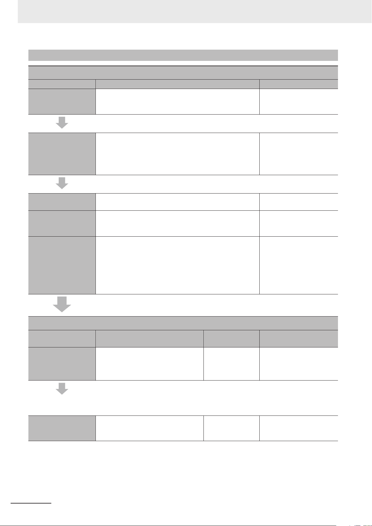
1 Introduction to NX-series Controllers
1-3-2
Procedure Details
STEP1. Software Design
Step Description Reference
Step 1-1
Designing I/O and
Processing
Step 1-2
Designing Tasks
Step 1-3
Designing Programs
POU (Program Organization Unit) Design
Variable Design
• External I/O devices and Unit configuration
• Refresh periods for external devices
• Program contents
• Task configuration
• Relationship between tasks and programs
• T
ask periods
• Slave and NX Unit refresh times
• Exclusive control methods for variables between tasks
• Programs
• Functions and function blocks
• Determining the algorithm languages
• Defining variables that you can use in more than one POU
and variables that you use in only specific POUs
• Defining the variables names for the device variables that
you use to access slaves and NX Units
• Defining the attributes of variables, such as the Name and
Retain attributes
• Designing the data types of variables
NJ/NX-series CPU Unit
Software User’
(Cat. No. W501)
NJ/NX-series CPU Unit
Software User’s Manual
(Cat. No. W501)
NJ/NX-series CPU Unit
Software User’
(Cat. No. W501)
NJ/NX-series CPU Unit
Software User’
(Cat. No. W501)
s Manual
s Manual
s Manual
STEP2. Software Setups and Programming
Step Description Sysmac Studio
Operations
Project Creation
The following Controller Configurations and Setup and the Programming and Task Settings can be performed in either or-
.
der
Step 2-1
Slave and NX Unit
Configurations
1. Create a project in the Sysmac Studio.
2. Select a Controller.
Select New Project
Select the device in
the Project Properties Dialog Box
Reference
Sysmac Studio Version 1
Operation Manual (Cat. No.
W504)
1-16
NX-series NX102 CPU Unit Hardware User’s Manual (W593)
Page 69

1 Introduction to NX-series Controllers
1-3 Overall Operating Procedure
1) Creating the Slave
and NX Unit Configurations
2) Assigning Device
Variables to I/O Ports
(The following step is for motion control.)
3) Creating the Axes
and Assigning Them to
the Servo Drive/Encoder Input Slaves
1. Creating the slave configuration and
NX Unit configuration either offline or
online. (For online configuration,
make the online connection that is
described in step 5.)
Setting up any Slave Terminals that
2.
are used.
Registering device variables in variable
tables (Variable names are user defined
or automatically created.)
Creating the axes and setting them as
real axes or virtual axes.
Creating axes groups to perform interpolated axes control.
EtherCAT Tab Page
CPU and Expansion Racks Tab
Page
Slave Terminal Tab
Page
I/O Map NJ/NX-series CPU Unit
Configurations
and Setup −
Motion Control
Setup
NJ/NX-series CPU Unit
Software User’s Manual
(Cat. No. W501)
NX-series EtherCAT Coupler
Units User’s Manual (Cat.
No. W519)
Software User’
(Cat. No. W501)
NJ/NX-series CPU Unit
Software User’
(Cat. No. W501)
s Manual
s Manual
for the CPU Unit
1
1-3-2 Procedure Details
Step 2-2
Controller Setup
Setting the following parameters from the
Sysmac Studio
Setting the initial values for the PLC
Function Module
Setting the battery-related error detection when the battery is mounted
Setting the initial values for the NX
Bus Function Module
(To use motion control)
Setting the initial settings for the
Motion Control Function Module
Setting the initial values for the
EtherCA
Setting the initial values for the
EtherNet/IP Function Module
T Function Module
Configurations
and Setup −
Controller Setup −
Operation Settings
Configurations
and Setup −
Controller Setup −
Operation Settings
Configurations
and Setup − CPU/
Expansion Racks
− CPU Rack
Configurations
and Setup −
Motion Control
Setup
Configurations
and Setup −
EtherCAT
Configurations
and Setup −
Controller Setup −
Built-in
EtherNet/IP Port
Settings
NJ/NX-series CPU Unit
Software User’
(Cat. No. W501)
3-1-5 Battery on page 3-12
s Manual
Step 2-3
Programming
NX-series NX102 CPU Unit Hardware User’s Manual (W593)
1-17
Page 70
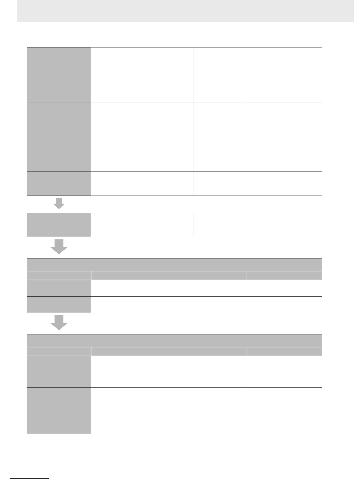
1 Introduction to NX-series Controllers
1) Registering Variables
• Registering the variables used by
more than one POU in the global variable table with Sysmac Studio
• Registering the local variable table for
each program
Global Variable Table Editor
Local Variable T
Editor
• Registering the local variable table for
each function block and function
2) Writing Algorithms
for POUs
3) Setting the Tasks Making task settings Configurations
Step 2-4
Offline Debugging
Writing the algorithms for the POUs (programs, function blocks, and functions) in
the required languages
Checking the algorithms and task execution times on the Simulator (virtual controller)
Programming Editor NJ/NX-series CPU Unit
and Setup − Task
Settings
Sysmac Studio Version 1
Operation Manual (Cat. No.
able
W504)
NJ/NX-series CPU Unit
Software User’s Manual
(Cat. No. W501)
Software User’s Manual
(Cat. No. W501)
NJ/NX-series Instructions
Reference Manua (Cat. No.
W502)
NJ/NX-series Motion Control
Instructions Reference
Manual (Cat. No. W508)
NJ/NX-series CPU Unit
Software User’
(Cat. No. W501)
NJ/NX-series CPU Unit
Software User’
(Cat. No. W501)
s Manual
s Manual
STEP3. Mounting and Setting Hardware
Step Description Reference
1) Mounting
2) Setting Hardware
• Connecting adjacent Units
• Mounting to DIN Track
• Setting the node addresses of the EtherCAT slaves
5-3 Mounting and Removing
Units on page
Operation manuals for the
EtherCAT slaves
STEP4. Wiring
Step Description Reference
1) Connecting the
Power Supply to the
CPU Unit
2) Connecting Ethernet
Cable
• Connecting the power supply and ground wires
• Connecting the built-in EtherCAT port
• Connecting the built-in EtherNet/IP port
Section 4 Designing the
Power Supply System on
page
4-1
iring on page 5-41
5-4 W
NJ/NX-series CPU Unit Builtin Ether-CA
Manual (Cat. No. W505)
NJ/NX-series CPU Unit Builtin EtherNet/IP Port User’s
Manual (Cat. No. W506)
5-9
T Port User’s
1-18
NX-series NX102 CPU Unit Hardware User’s Manual (W593)
Page 71
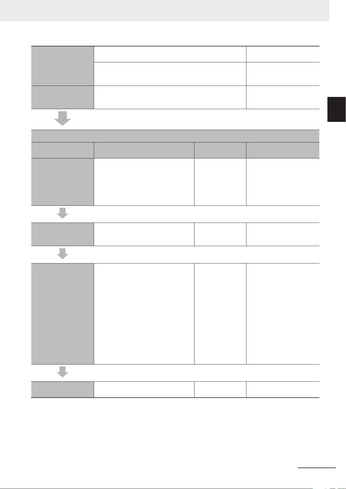
1 Introduction to NX-series Controllers
1-3 Overall Operating Procedure
3) Wiring I/O
4) Connecting the
Computer That Runs
the Sysmac Studio
• Wiring I/O for NX Units
• Wiring I/O to EtherCAT slaves
• Connecting the built-in EtherNet/IP port
Manuals for the specific NX
Units
Operation manuals for the
EtherCAT slaves
iring on page 5-41
5-4 W
Sysmac Studio Version 1
Operation Manual (Cat. No.
W504)
STEP5. Checking Operation and Starting Operation on the Actual System
Step Description Sysmac Studio
Operations
1) Online Connection
to Sysmac Studio and
Project Download
Turn ON the power supply to the Controller and place the Sysmac Studio online.
Then, download the project.
Perform this step before you create the
slave configuration or NX Unit configuration from the mounted Units in step 2-1.
*1
Controller −
Communications
Setup −
Controller −
Synchronization
Reference
NJ/NX-series CPU Unit
Software User’s Manual
(Cat. No. W501)
for the CPU Unit
1
1-3-2 Procedure Details
2) Clock Data Setting Set the clock data with the clock function
when the battery is mounted.
3) Operation Check on
Controller
4) Actual Controller
Operation
*1. Use the Synchronize Menu of the Sysmac Studio to download the project.
1. Check the wiring by using forced re-
freshing of real I/O from the I/O Map
or Watch T
2. For motion control, use the MC Test
Run operations in PROGRAM mode
to check the wiring. Then check the
motor rotation directions for jogging,
travel distances for relative positioning (e.g., for electronic gear settings),
and homing operation.
3. Change the Controller to RUN mode
and check the operation of the user
program.
Start actual operation. --- ---
ab Page.
Controller −
Controller Clock
--- NJ/NX-series CPU Unit
NJ/NX-series CPU Unit
Software User’
(Cat. No. W501)
Software User’s Manual
(Cat. No. W501)
s Manual
NX-series NX102 CPU Unit Hardware User’s Manual (W593)
1-19
Page 72

1 Introduction to NX-series Controllers
1-20
NX-series NX102 CPU Unit Hardware User’s Manual (W593)
Page 73

2
2
System Configuration
This section describes the basic system configuration used for NX-series Controllers.
2-1 Basic System Configuration
2-1-1 EtherCAT Network Configuration .................................................................... 2-3
2-1-2 NX Unit Configuration...................................................................................... 2-4
2-2 Connecting to the Sysmac Studio ................................................................ 2-6
2-3 Network Configuration................................................................................... 2-7
......................................................................... 2-2
NX-series NX102 CPU Unit Hardware User’s Manual (W593)
2-1
Page 74

2 System Configuration
2-1
Basic System Configuration
An NX-series Controller NX102 supports the following two types of configurations.
• Basic Configuration
The basic configurations include the CPU Unit and the Configuration Units that are controlled direct-
ly by the CPU Unit. There are two basic configurations.
a) EtherCAT network configuration
b) NX Unit configuration
• Other Network Configurations
These are the configurations of the systems that are connected to the CPU Unit’s built-in
EtherNet/IP ports and Communications Units.
Basic Controller Configuration
EtherCAT Network Configuration
l
With an NX-series CPU Unit, you can use an EtherCAT network as a basic system.
With the EtherCAT network system of the NX-series CPU Unit, the period for sequence processing
and motion processing in the CPU Unit is the same as the EtherCAT communications period.
This enables high-precision sequence control and motion control with a constant period and little
fluctuation.
For information on EtherCAT, refer to the NJ/NX-series CPU Unit Built-in EtherCAT Port User’s
Manual (Cat. No. W505).
NX Unit Configuration
l
The CPU Rack consists of the following items.
• NX102 CPU Unit
• NX Unit NX-£££££££
• End Cover NX-END02
Up to 32 NX Units can be connected.
By using the NX Units that support synchronous I/O refreshing, all I/O refreshing is synchronized
with the task period of the primary periodic task of the CPU Unit.
This enables high-precision synchronized control with a stable fixed period.
2-2
NX-series NX102 CPU Unit Hardware User’s Manual (W593)
Page 75

ADR ADR
NX-series
NX102 CPU Unit
SD Memory
Card
Slave Terminal
Servo Drives/
Encoder input slaves
General-purpose
slaves
EtherCAT slaves
Built-in EtherNet/IP port 2
Built-in EtherNet/IP port 1
Built-in EtherCAT port
EtherCAT
CPU Rack
End Cover
2 System Configuration
2-1-1
EtherCAT Network Configuration
The EtherCAT network configuration consists of an NX-series NX102 CPU Unit, an End Cover, and
the EtherCA
Y
ou use the built-in EtherCAT port on the NX-series NX102 CPU Unit to connect EtherCAT slaves.
T slaves.
2-1 Basic System Configuration
2
2-1-1 EtherCAT Network Configuration
For information on the system configuration of an EtherCAT network, refer to the NJ/NX-series CPU
Unit Built-in EtherCA
T Port User
’s Manual (Cat. No. W505).
Refer to 2-1-2 NX Unit Configuration on page 2-4 for information on the CPU Unit and End Cover.
NX-series NX102 CPU Unit Hardware User’s Manual (W593)
2-3
Page 76

NX-series
NX102 CPU Unit
SD Memory Card
End CoverNX Units
(32 Units max.)
2 System Configuration
2-1-2
NX Unit Configuration
The following shows the configuration of NX Units.
CPU Rack
The CPU Rack consists of an NX-series NX102 CPU Unit, NX Units, and an End Cover.
Up to 32 NX Units can be connected.
Series Configuration Remarks
NX-series NX-series NX102 CPU Unit One required for every CPU Rack.
End Cover Must be connected to the right end of the CPU
Rack. One End Cover is provided with the
CPU Unit.
NX Units Digital I/O Unit Up to 32 Units can be mounted to each CPU
Analog I/O Unit
System Unit
Position Interface Unit
Communication Interface
Unit
Load Cell Input Unit
NJ/NX-series SD Memory Card Install as required.
Rack.
Refer to A-5 Support Functions of the CPU
Units and Restrictions on the NX Units on page
A-10 for information such as restrictions on
the NX Units.
For information on the most recent lineup of
NX Units, refer to NX-series catalogs or OMRON websites, or ask your OMRON representative.
2-4
NX-series NX102 CPU Unit Hardware User’s Manual (W593)
Page 77

2 System Configuration
Configuration Units
NX-series NX102 CPU Unit
l
The Unit that serves as the center of control for a Machine Automation Controller. It executes tasks,
refreshes I/O for other Units and slaves, etc. In the NX-series, this type of Units is called NX102
CPU Unit.
Refer to 3-1 CPU Units on page
NX102 CPU Unit.
SD Memory Card
l
With the NX-series NX102 CPU Unit, various data can be saved, backed up, restored, and com-
pared using the SD Memory Card.
Refer to 3-2 SD Memory Cards on page 3-15 for the models and specifications of individual SD
Memory Cards.
3-2 for the models and specifications of individual NX-series
2-1 Basic System Configuration
2
2-1-2 NX Unit Configuration
NX Unit
l
The NX Units perform I/O processing with connected external devices. These Units are NX-series
NX-££££££ Units.
Up to 32 NX Units can be connected to the CPU Unit.
Refer to A-5 Support Functions of the CPU Units and Restrictions on the NX Units on page A-10
for information such as restrictions on the NX Units.
End Cover
l
A cover to protect the NX Unit and CPU Unit. This is provided with the CPU Unit. The model num-
ber is NX-END02.
Recommended Communications Cables for EtherCAT and EtherNet/IP
l
EtherCAT communications are performed in accordance with the 100BASE-TX standard. Refer to
the NJ/NX-series CPU Unit Built-in EtherCAT Port User
ed cables.
EtherNet/IP communications are performed in accordance with the 100BASE-TX or 10BASE-T
standard. Refer to the NJ/NX-series CPU Unit Built-in EtherNet/IP Port User’s Manual (Cat. No.
W506) for recommended cables.
’s Manual (Cat. No. W505) for recommend-
NX-series NX102 CPU Unit Hardware User’s Manual (W593)
2-5
Page 78

2 System Configuration
2-2
Connecting to the Sysmac Studio
Connect the NX-series NX102 CPU Unit and the Sysmac Studio through EtherNet/IP.
Refer to 3-5-2 Connection on page 3-18 for information on how to make the connection between the
NX-series NX102 CPU Unit and the Sysmac Studio.
2-6
NX-series NX102 CPU Unit Hardware User’s Manual (W593)
Page 79

EtherCAT
Slave Terminal
Vision Systems
Sysmac
Studio
EtherNet/IP
DeviceNet
EtherCAT
CompoNet
REMOTE TERMINAL
01 2 3 4 5 6 7 8 9 10 11 12 13 14 15
OUT
CRT1-OD16
MS NS
WORD NODE ADR
REMOTE TERMINAL
01 2 3 4 5 6 7 8 9 10 11 12 13 14 15
OUT
CRT1-OD16
MS NS
WORD NODE ADR
REMOTE TERMINAL
01 2 3 4 5 6 7 8 9 10 11 12 13 14 15
OUT
CRT1-OD16
MS NS
WORD NODE ADR
EtherNet/IP
Built-in EtherNet/IP port 1
Built-in EtherNet/IP port 2
Built-in
EtherCAT port
Built-in EtherNet/IP ports
CompoNet Master Unit
CompoNet slaves
DeviceNet slaves
DeviceNet Unit
NJ-series
CPU Unit
Field Level
NX-series
NX102
CPU Unit
Serial
Communications
Unit
RS-232C,
RS-422A/485
RFID system Robots
Servo Drives
General-purpose
slaves
Serial communications devices
NX-series Communications
Interface Unit
General-purpose components or OMRON components
Serial communications devices
General-purpose components or OMRON components
NJ/NX-series
CPU Unit
Programmable
terminal
FA Wireless
LAN Unit
FA
Communications
Software
Information
Level
2 System Configuration
2-3
Network Configuration
You can make networks in the following layers with an NJ/NX-series Controller.
For details on communications networks that you can connect to, refer to the NJ/NX-series CPU Unit
Software User’s Manual (Cat. No. W501).
2-3 Network Configuration
2
NX-series NX102 CPU Unit Hardware User’s Manual (W593)
2-7
Page 80

2 System Configuration
Sysmac Studio Use USB or the built-in EtherNet/IP port.
Between Controllers
Devices Servo Drives, general-purpose slaves
Programmable Terminals Use the built-in EtherNet/IP port or a port on an
Servers Connections to BOOTP server, DNS
*1. Use a CJ-series EtherNet/IP Unit with a unit version of 2.1 or later.
Also, mount the EtherNet/IP Unit to an NJ-series CPU Unit with unit version 1.01 or later, and use Sysmac Studio version
1.02 or higher
Refer to the NJ/NX-series CPU Unit Software User’s Manual (Cat. No. W501) for information on version upgrades.
*2. Mount to an NJ-series CPU Unit.
*3. Mount the Unit to the NX-series NX102 CPU Unit.
.
Connection Connection method
For NX102 CPU Unit
can be used.
NJ/NX-series Controller or CJ-series PLC Use the built-in EtherNet/IP port or a port on an
EtherNet/IP Unit.
Use the built-in EtherCA
and Vision Systems
Ethernet communications devices Use the built-in EtherNet/IP port or a port on an
EtherNet/IP Unit.
Serial communications devices Mount the following Units and use RS-232C port or
RS-422A/485 ports.
• CJ-series Serial Communications Unit
• NX-series Communications Interface Unit
DeviceNet slaves
CompoNet slaves
server, or NTP server
Mount a CJ-series DeviceNet Unit*2 and use DeviceNet.
Mount a CJ-series CompoNet Master Unit*2 and use
CompoNet.
EtherNet/IP Unit.
Use the built-in EtherNet/IP port or a port on an
EtherNet/IP Unit.
, only the built-in EtherNet/IP ports
*1
T port.
*1
*2
*3
*1
*1
2-8
NX-series NX102 CPU Unit Hardware User’s Manual (W593)
Page 81

Configuration Units
3
3
This section describes configuration devices in the NX-series Controller configuration.
3-1 CPU Units
3-1-1 Models and Specifications............................................................................... 3-2
3-1-2 Part Names and Functions .............................................................................. 3-4
3-1-3 Operation Status Indicators ............................................................................. 3-6
3-1-4 Terminal Blocks ..............................................................................................3-11
3-1-5 Battery ........................................................................................................... 3-12
3-1-6 ID Information Indication ............................................................................... 3-13
3-2 SD Memory Cards ........................................................................................ 3-15
3-2-1 Models and Specifications............................................................................. 3-15
3-2-2 Purpose ......................................................................................................... 3-15
3-3 Power Supply-related Units ........................................................................ 3-16
3-4 NX Units ........................................................................................................ 3-17
3-5 Sysmac Studio ............................................................................................. 3-18
3-5-1 Model Numbers ............................................................................................. 3-18
3-5-2 Connection .................................................................................................... 3-18
........................................................................................................ 3-2
NX-series NX102 CPU Unit Hardware User’s Manual (W593)
3-1
Page 82

3 Configuration Units
3-1
3-1-1
CPU Units
This section describes the models and specifications of the CPU Units as well as the names and func-
tions of the parts.
Models and Specifications
This section describes the outline of the CPU Unit specifications. The electrical and mechanical speci-
fications of the CPU Unit are also given. Refer to 1-2 Specifications on page 1-9 for information on
other main specifications.
Models and Outline of Specifications
The models and outline of specifications are given below.
Maximum number of
Model
NX102-1200 5 MB 1.5 MB (Retained during power interruptions)
NX102-1100 15 axes (8 axes)
NX102-1000 15 axes (6 axes)
NX102-9000 4 axes (4 axes)
NX102-1220 15 axes (12 axes) Supported
NX102-1120 15 axes (8 axes)
NX102-1020 15 axes (6 axes)
NX102-9020 4 axes (4 axes)
Program
capacity
Memory capacity for variables
or 32 MB (Not retained during power interruptions)
controlled axes
(Maximum number of
used real axes)
15 axes (12 axes) Not supported
Database
connection
3-2
NX-series NX102 CPU Unit Hardware User’s Manual (W593)
Page 83

3 Configuration Units
Electrical and Mechanical Specifications
The electrical and mechanical specifications are given below.
Item Specification
Model
Enclosure Mounted in a panel
Dimensions (mm)
*2
Weight
Unit power supply
Power supply to the NX
Unit power supply
I/O Power Supply to NX Units
External connection terminal
*1. Includes the End Cover, and does not include projecting parts.
*2. Includes the End Cover. The weight of the End Cover is 82 g.
*3. Includes an SD Memory Card. The NX Unit power consumption to NX Units is not included.
*4. The inrush current that occurs when the supplied power is changed to ON from a continuous OFF state.
The inrush current may vary depending on the operating condition and other conditions. Therefore, select
fuses, breakers, and external power supply devices that have enough margin in characteristic and capacity,
considering the condition under which the devices are used.
In particular
er supply, if the duration of an ON-OFF-ON cycle is one second or less, the inrush control circuit may not
function, which cause an inrush current of approximately 30 A/0.3 ms.
*5. The amount of current that can be passed constantly through the terminal. Do not exceed this current value
when you use a through-wiring for the Unit power supply.
*6. When the type of the I/O power supply to NX Units you use is the supply from NX bus, an Additional I/O
Power Supply Unit is required. Refer to 4-3 Designing the I/O Power Supply System on page 4-13
tails.
*1
Power supply voltage 24 VDC (20.4 to 28.8 VDC)
Unit power consumption
Inrush current
Current capacity of power
supply terminal
Isolation method
NX Unit power supply capacity
NX Unit power supply efficiency
Isolation method
Communication connector
Screwless clamping terminal block
Output terminal (service
supply)
RUN output terminal Not provided
NX bus connector 32 NX Units can be connected
, in case when you insert a switch to turn ON/OFF the DC power supplied from an external pow-
*4
*5
NX102-££££
72 × 100 × 90 mm (W×H×D)
390 g max.
*3
5.80 W max.
For cold start at room temperature:
10 A max./0.1 ms max.
and
2.5 A max./150 ms max.
4 A max.
No isolation: between the Unit power supply terminal and internal circuit
10 W max.
80%
No isolation: between the Unit power supply terminal and NX Unit power supply
Not provided
RJ45 for EtherNet/IP Communications × 2
RJ45 for EtherCA
For Unit power supply input and grounding (Removable)
Not provided
*6
T Communications × 1
for de-
3-1 CPU Units
3
3-1-1 Models and Specifications
NX-series NX102 CPU Unit Hardware User’s Manual (W593)
3-3
Page 84
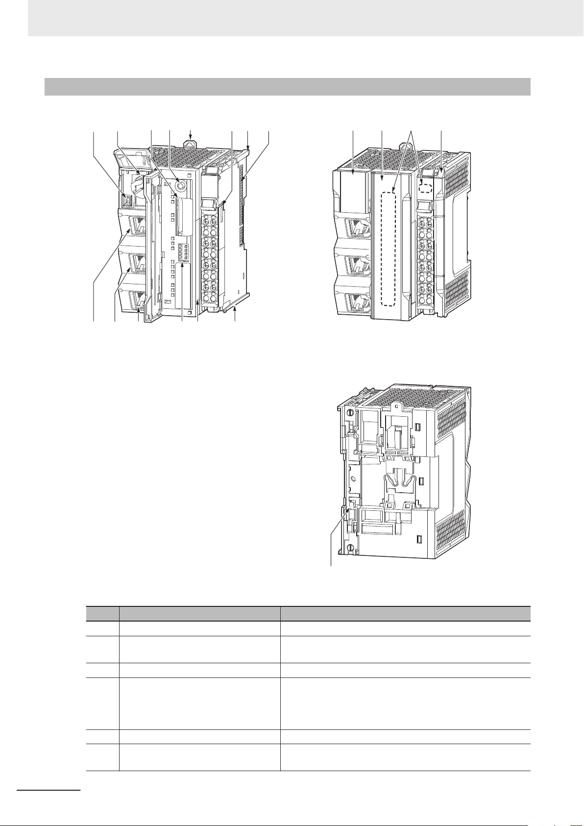
(A)
(B)
(C) (D)
(G) (H)
(E)
(F)
(N)
(I)
(O) (Q)(P)
(J)(M) (K)(L) (G)
(R)
3 Configuration Units
3-1-2
Part Names and Functions
This section explains parts of the CPU Unit and their functions.
Letter Name Function
A Battery connector Connects a separately-sold backup battery to the CPU Unit.
B Battery slot Allows a separately-sold backup battery to be mounted into
C SD Memory Card connector Connects the SD Memory Card to the CPU Unit.
D SD Memory Card power supply switch Turns OFF the power supply so that you can remove the SD
DIN Track mounting hook This hook is used to mount the NX Unit to a DIN Track.
E
F Terminal block The terminal block is used for wiring for the Unit power supply
the CPU Unit.
Memory Card.
5-3-8 Installing and Removing the SD Memory Card on page
5-27
and grounding cable.
3-4
NX-series NX102 CPU Unit Hardware User’s Manual (W593)
Page 85
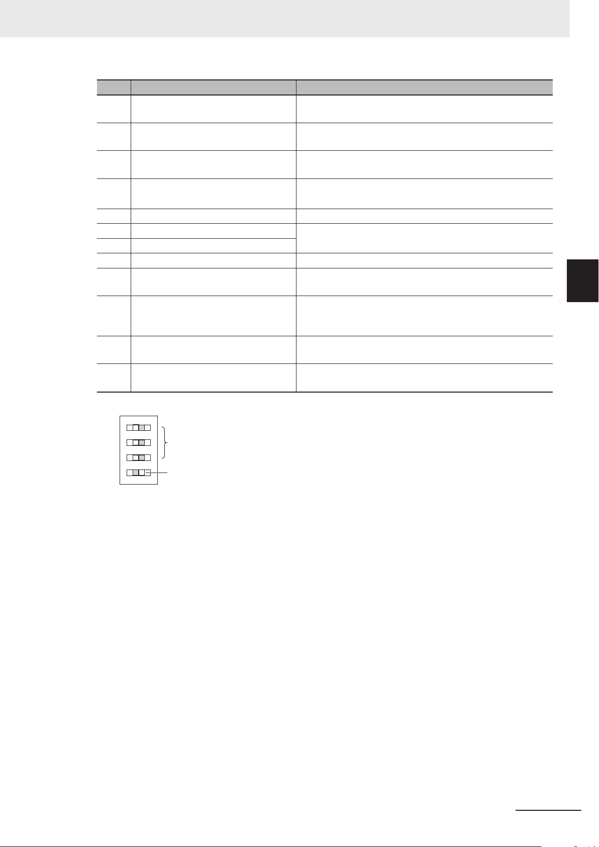
OFF
O
N
O
N
1
2
3
4
3 Configuration Units
Letter Name Function
G Unit hookup guides These guides are used to mount an NX Unit or the End Cov-
er.
NX bus connector This connector is used to connect the NX Unit mounted on
H
the right side.
I ID information indication Shows the ID information of the CPU Unit.
3-1-6 ID Information Indication on page 3-13
DIP switch
J
K
Built-in EtherCAT port (port 3) Connects the built-in EtherCAT with an Ethernet cable.
L Built-in EtherNet/IP port (port 2) Connects the built-in EtherNet/IP with an Ethernet cable.
M Built-in EtherNet/IP port (port 1)
N Battery cover A cover for the battery slot. It opens upward.
O SD Memory Card A cover for the SD Memory Card and the DIP switch. It opens
P Operation Status Indicators Shows the operation status of the CPU Unit by multiple indi-
Q End Cover A cover to protect the NX Unit and CPU Unit.
R DIN Track contact plate This plate is used to contact the functional ground terminal
*1. To use Safe Mode, set the DIP switch as shown below and then turn ON the power supply to the Controller.
Used in Safe Mode*1 or when backing up data*2. Normally,
turn OFF all of the pins.
Use port 1 to perform OPC UA communications.
toward the left.
cators.
3-1-3 Operation Status Indicators
on page
3-6
One End Cover is provided with the CPU Unit.
with a DIN Track.
3-1 CPU Units
3
3-1-2 Part Names and Functions
If the power supply to the Controller is turned ON with the CPU Unit in Safe Mode, the CPU Unit will start in
PROGRAM mode. Use the Safe Mode if you do not want to execute the user program when the power supply is turned ON or if it is difficult to connect the Sysmac Studio.
For information on Safe Mode, refer to the
*2. Refer to the NJ/NX-series CPU Unit Software User’
NX-series NX102 CPU Unit Hardware User’s Manual (W593)
NJ/NX-series Troubleshooting Manual (Cat. No. W503).
s Manual (Cat. No. W501) for details on backing up data.
3-5
Page 86
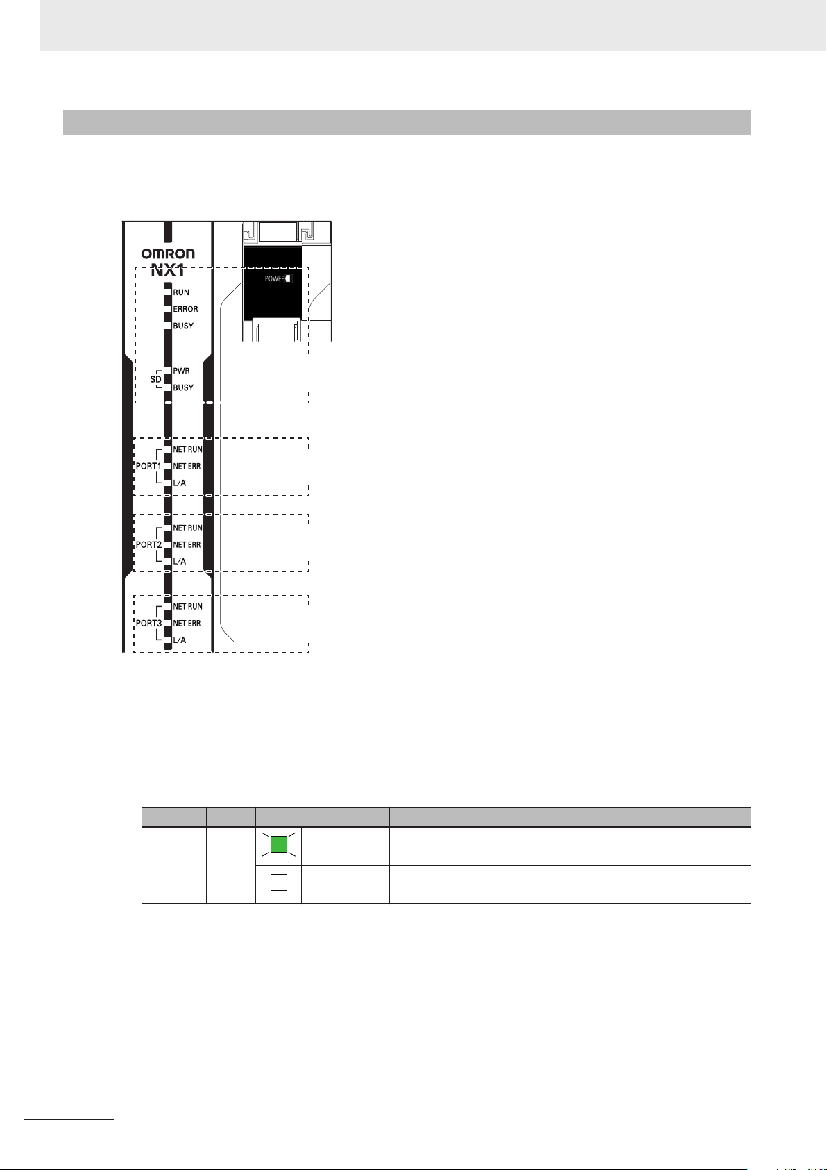
Built-in EtherNet/IP (Port 1)
Status Indicators
Built-in EtherNet/IP (Port 2)
Status Indicators
Built-in EtherCAT (Port 3)
Status Indicators
CPU Unit
Status indicators
3 Configuration Units
3-1-3
Operation Status Indicators
There are the indicators to show the operation status of CPU Unit in the center of the front side of the
CPU Unit
.
CPU Unit Status Indicators
l
These indicators show the main operation status of the CPU Unit.
The following table describes these indicators. The POWER indicator is located on the top of the
terminal block.
Indicator Color Status Meaning
POWER Green
Lit. Power is ON.
Not lit. Power is not ON. Or, the power supply voltage is outside the allowable
voltage range.
3-6
NX-series NX102 CPU Unit Hardware User’s Manual (W593)
Page 87
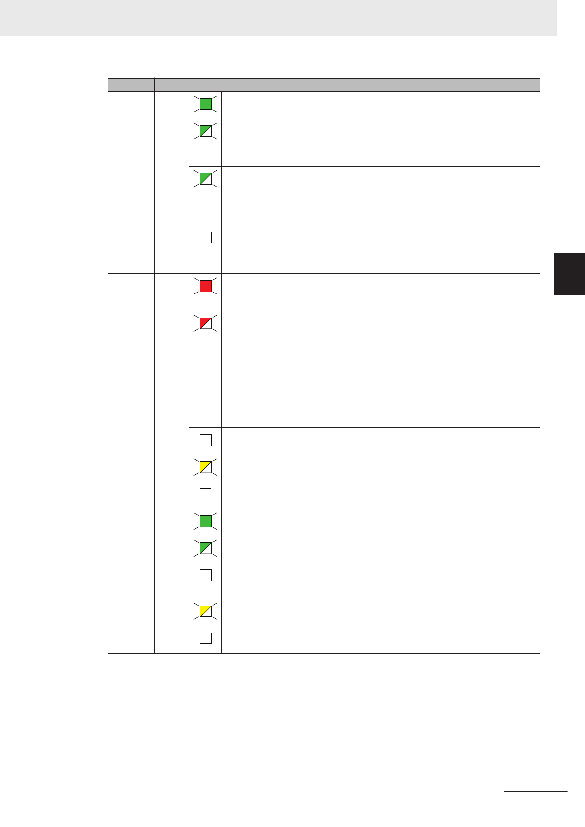
3 Configuration Units
Indicator Color Status Meaning
RUN Green Lit. The CPU Unit is in normal operation in RUN mode. (The user program
is in execution.)
Flashing
at 2-s intervals,
then flashing at
0.5-s intervals.
Flashing
at 2-s intervals
continues for
30 seconds or
longer.
Not lit. Operation is stopped in PROGRAM mode, when a CPU Unit reset is in
ERROR Red Lit. Self-diagnosis found one of the following errors.
Flashing
at 1-s intervals.
Not lit. The CPU Unit is in normal operation, a CPU reset is in progress, or
BUSY
Yellow
Flashing Built-in non-volatile memory access in progress.
The CPU Unit is starting (entering RUN mode or PROGRAM mode at
startup).
System initialization error occurs.
progress, or when any of the following errors occurs.
• Controller error in the major fault level
• CPU error (WDT error)
• Controller error in the major fault level
• CPU error
Self-diagnosis found one of the following errors.
• Controller error in the partial fault level (an error in which all control
of a Function Module is disabled)
• Controller error in the minor fault level (an error in which partial con-
trol of a Function Module is disabled)
CPU Unit operation will continue for either of these errors.
Operation will stop for the Function Module in which a Controller error
in the partial fault level occurred.
Operation will continue for the Function Module in which a Controller
error in the minor fault level occurred.
monitored information occurred (CPU Unit operation will continue.).
3-1 CPU Units
3
3-1-3 Operation Status Indicators
Not lit. Other than the above.
SD PWR Green Lit. Power is being supplied to the SD Memory Card and the SD Memory
Card can be used.
Flashing
Not lit. The power supply for the SD Memory Card is stopped, an SD Memory
SD BUSY Yellow Flashing SD Memory Card access in progress.
Not lit. SD Memory Card access not in progress.
*1. Refer to the NJ/NX-series CPU Unit Software User’
A backup, restore or verification operation is in progress.
Card is not mounted, or the file format of the mounted SD Memory
Card is not supported.
s Manual (Cat. No. W501) for details on backing up data.
*1
NX-series NX102 CPU Unit Hardware User’s Manual (W593)
3-7
Page 88
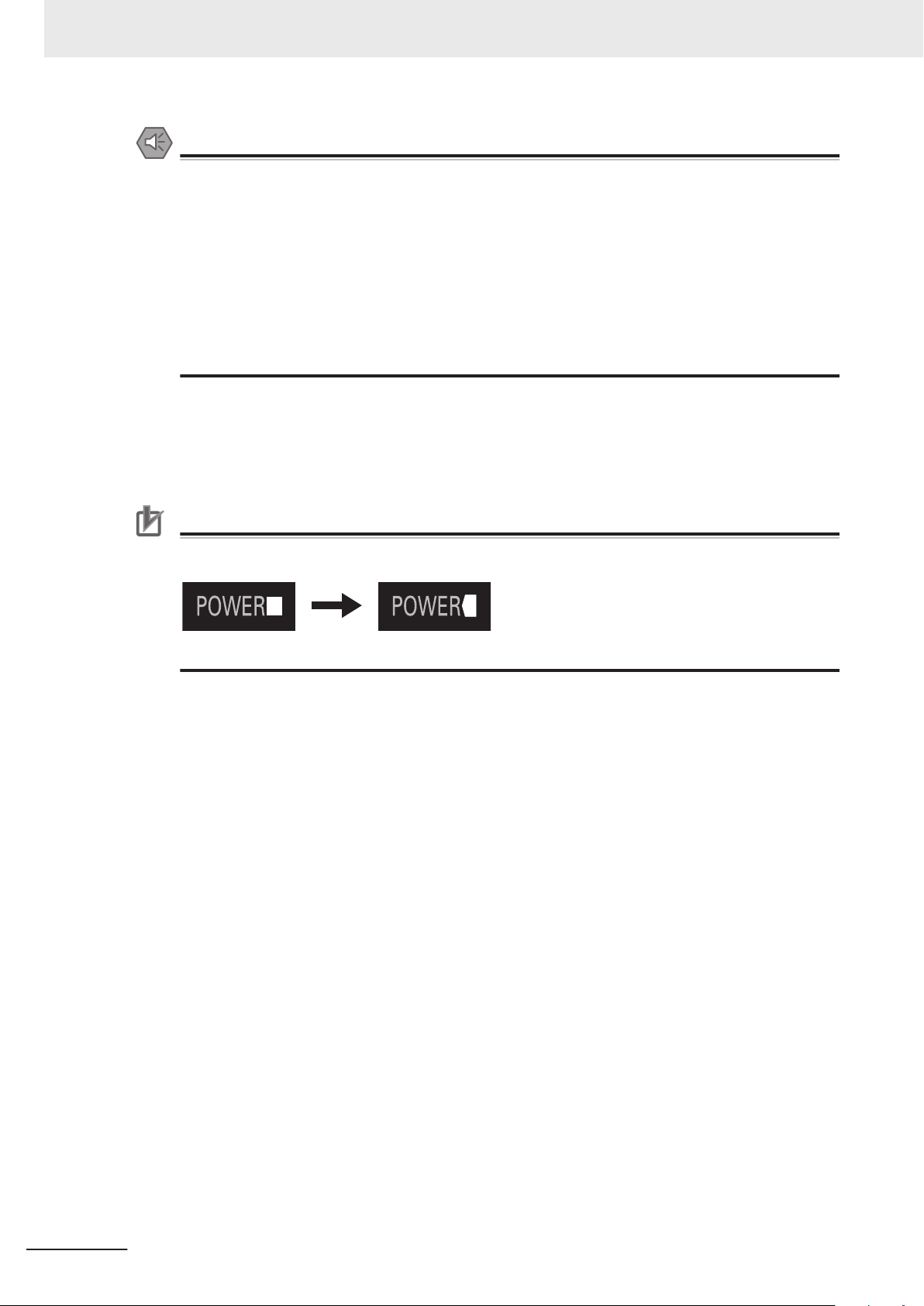
Before change After change
3 Configuration Units
Precautions for Safe Use
• Never turn OFF the power supply to the Controller when the BUSY indicator is flashing. While
the BUSY indicator is lit, the user program and settings in the CPU Unit
in the built-in non-volatile memory. The data will not be backed up if the power supply is
turned OFF. Also, a major fault level Controller error will occur the next time you start operation, and operation will stop.
• Do not turn OFF the power supply or remove the SD Memory Card while SD Memory Card
access is in progress (i.e., while the SD BUSY indicator flashes). Data may become corrupted, and the Controller will not operate correctly if it uses corrupted data. To remove the SD
Memory Card from the CPU Unit while the power supply is ON, press the SD Memory Card
power supply switch and wait for the SD BUSY indicator and SD PWR indicator to turn OFF
before you remove the SD Memory Card.
You can check the operation status of the CPU Unit with the CPU Unit status indicators (POWER,
RUN, and ERROR indicators).
Refer to the NJ/NX-series Troubleshooting Manual (Cat. No. W503) for the procedures to check the
operation status of the CPU Unit
are being backed up
.
Precautions for Correct Use
For products with lot numbers that represent the date of or after March 20, 2019, the shape of
the light emitting part of each indicator has been changed from a square to a pentagon.
3-8
NX-series NX102 CPU Unit Hardware User’s Manual (W593)
Page 89
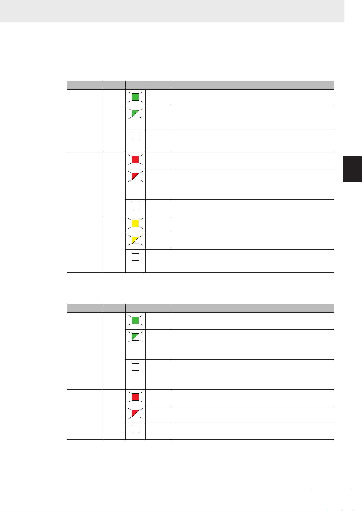
3 Configuration Units
Built-in EtherNet/IP (Port 1/Port 2) Status Indicators
l
These indicators show the operation status of the built-in EtherNet/IP ports of the CPU Unit. The
indicator name and other information are the same for port 1 and port 2.
Indicator Color Status Meaning
NET RUN Green Lit. Normal startup status.
Flashing Ethernet communications are in progress.
• Tag data link connection establishment in progress.
• IP address acquisition with BOOTP in progress.
Not lit. You cannot perform Ethernet communications.
• The power supply is OFF or the CPU Unit was reset.
• A MAC address error or communications Controller error occurred.
NET ERR Red
L/A Yellow
Lit. An error for which the user cannot recover operation occurred.
• A MAC address error or communications Controller error occurred.
Flashing An error for which the user can recover operation occurred.
• An error occurred in TCP/IP communications or CIP communications.
• FTP server setting error, NTP server setting error
, etc.
• Tag data link setting error, tag data link verification error, etc.
Not lit. There are no Ethernet communications errors.
• The power supply is OFF or the CPU Unit was reset.
Lit. The link was established.
3-1 CPU Units
3
3-1-3 Operation Status Indicators
Flashing The link is established, and data communications are in progress.
Not lit. A link was not established.
• The cable is not connected.
• The power supply is OFF or the CPU Unit was reset.
Built-in EtherCAT (Port 3) Status Indicators
l
These indicators show the operation status of the built-in EtherCAT port of the CPU Unit.
Indicator Color Status Meaning
NET RUN Green Lit. EtherCAT communications are in progress.
• Inputs and outputs for I/O data are in operation.
Flashing EtherCAT communications are established.
This indicator shows either of the following conditions.
• Only message communications are in operation.
• Only message communications and I/O data inputs are in operation.
Not lit. EtherCAT communications are stopped.
• The power supply is OFF or the CPU Unit was reset.
• A MAC address error, communications Controller error, or other error
occurred.
NET ERR Red Lit. A hardware error or unrecoverable error occurred, such as for exception
processing.
Flashing A recoverable error occurred.
Not lit. There are no errors.
NX-series NX102 CPU Unit Hardware User’s Manual (W593)
3-9
Page 90

3 Configuration Units
Indicator Color Status Meaning
L/A Yellow Lit. A link is established.
Flashing Data communications are in progress after establishing link.
Flashes every time data is sent or received.
Not lit. The link was not established.
3-10
NX-series NX102 CPU Unit Hardware User’s Manual (W593)
Page 91
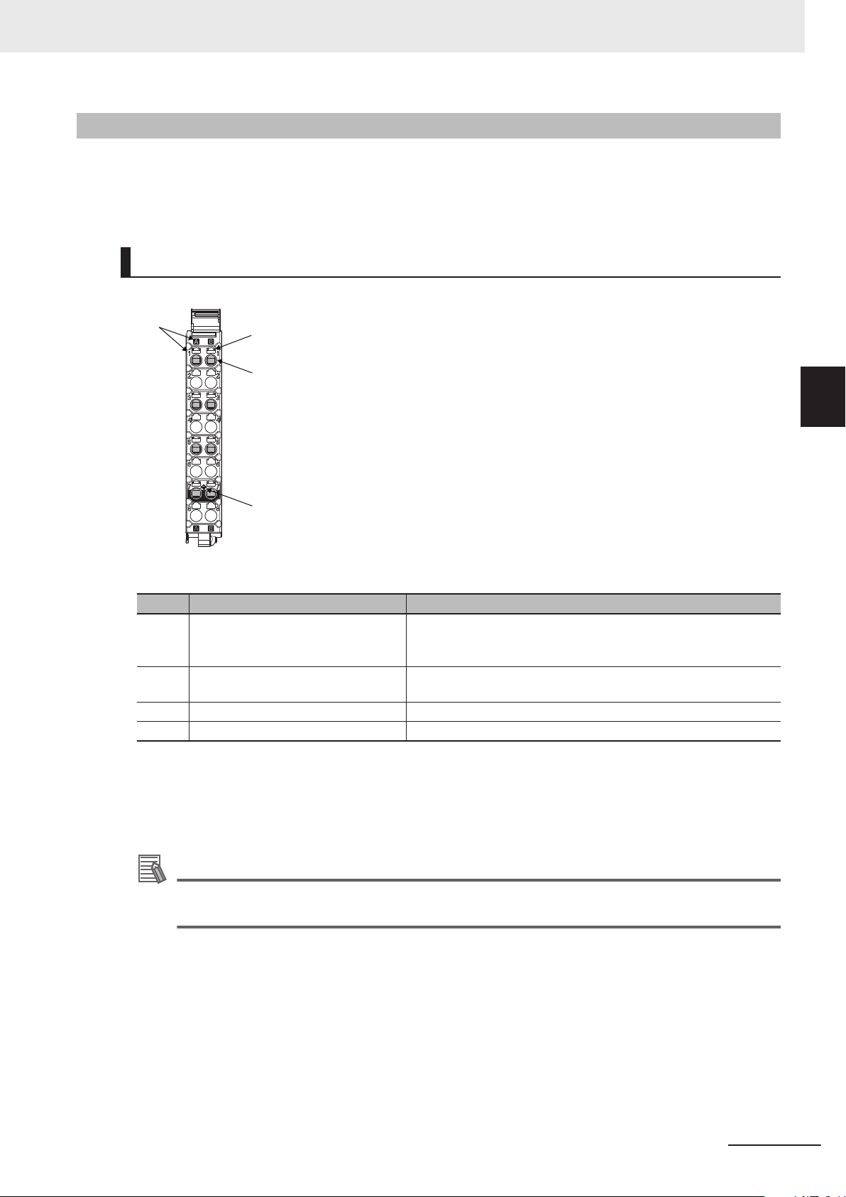
(A)
A1
A2
A3
A4
A5
A6
A7
A8
B1
B2
B3
B4
B5
B6
B7
B8
(B)
(C)
(D)
NX-TBC082
8-terminal type
3 Configuration Units
3-1-4
Terminal Blocks
The terminal blocks on the CPU Unit are removable screwless clamping terminal blocks that allow you
to easily connect and remove the wiring.
Connect the Unit power supply and ground lines to the screwless clamping terminal block.
Terminal Block Part Names and Functions
3-1 CPU Units
3
3-1-4 Terminal Blocks
NX-series NX102 CPU Unit Hardware User’s Manual (W593)
Letter Name Function
(A) Terminal number indication Indicates the terminal numbers (A1 to A8 and B1 to B8).
The terminal number indication is the same regardless of the number of
terminals on the terminal block.
(B) Release hole Insert a flat-blade screwdriver into this hole when you connect or re-
move the wire.
(C) Terminal hole The wire is inserted into this hole.
(D) Ground terminal mark This symbol indicates that it is the ground terminal.
Refer to 5-4-8 Wiring to the CPU Unit T
erminal Block on page 5-49 for the wiring procedure.
There are three types of terminal blocks: 8-terminal type, 12-terminal type, and 16-terminal type.
Only the 8-terminal type terminal block can be attached to the NX102 CPU Units.
To prevent mis-insertion, the terminal blocks other than of the 8-terminal type cannot be used.
Additional Information
No terminal and release holes with the numbers A2, A4, A6, A8, B2, B4, B6, and B8 are provided for the 8-terminal type terminal block.
3-11
Page 92

3 Configuration Units
3-1-5
Battery
The battery is not mounted when the product is shipped.
ou need to prepare a battery for the CPU Unit to retain the clock data while the CPU Unit is left pow-
Y
ered of
f for a long period of time.
The following describes the purpose of the battery mounting, the battery model, and the battery-relat-
ed error detection and clock data settings.
Purpose of the Battery Mounting
The battery is used to retain the clock data while the power is not supplied to the CPU Unit. The clock
data is retained by the built-in capacitor whether the battery is mounted or not, but the retention period
depends on the continuous power-ON time of the CPU Unit, as shown below.
Retention period
Continuous power-
ON time of CPU
*1
Unit
100 hours Approx. 10 days
8 hour Approx. 8 days
1 hour Approx. 7 days
*1. This is equivalent to the time to charge a built-in capacitor in which no electric charge is accumulated.
during no power
supply at an ambient temperature of
40°C
When you use the clock data for programming, use a battery if you cannot ensure the continuous pow-
er-ON time shown above or the power-OFF time is longer than the above power-ON time.
The following data (other than the clock data) is retained in the built-in non-volatile memory, so they
are not lost even if the battery and built-in capacitor are fully discharged.
•
User program
• Set values
• Variables retained during power interruption
• Event logs
Battery Model
The table below shows the model and specifications of the battery that can be used.
Model Appearance Specification
CJ1W-BAT01 Service life: 5 years
For the battery lifetime, refer to Battery Service
Life and Replacement Period on page 7-7.
The clock information is retained during power interruptions.
3-12
NX-series NX102 CPU Unit Hardware User’s Manual (W593)
Page 93

(A)
(D)
LOT No. DDMYY£ xxxx
PORT1
££££££££££££
PORT2
££££££££££££
Ver.£.££ HW Rev.£
(B) (C)
3 Configuration Units
Battery-related Error Detection and Clock Data Settings
Because the CPU Unit is shipped with the battery not mounted, the Battery-related error detection is
set to Do not use by default.
The behavior of the CPU Unit when a battery-related error is detected depends on whether battery er-
ror detection is used or not used as shown in the table below.
When the battery is not mounted, you can set the
suppress battery errors.
When the battery is mounted, however, you can set the Battery-related error detection to Use to de-
tect battery errors.
Battery-related error detection to Do not use to
3-1 CPU Units
Behavior
When the Battery-related error
detection is set to
Use
Cause of error
One of the following was detected
at power ON.
• Built-in capacitor discharged
• Battery not mounted
• Mounted battery discharged
What is af-
fected
Clock data
When the Battery-related error
detection is set to Do not use
• In case of clock oscillator stopping
T
ime measurement starts from January 1st, 1970.
• In case of low battery voltage
T
ime measurement continues.
Error detection No error is detected. The following error is detected.
• Low Battery Voltage
• Real-Time Clock Stopped
One of the following was detected
after power ON.
• Battery was removed
Clock data Time measurement continues.
Error detection No error is detected. The following error is detected.
• Low Battery Voltage
• Mounted battery discharged
When you mount the battery, set the Battery-related error detection to Use.
The measurement of clock data starts from January 1st, 1970 if the clock oscillator stops. If this oc-
curs, readjust the CPU Unit’s clock data to the current time.
In order to use the clock data for programming, you need to use system-defined variables to read the
presence or absence of the Low Battery V
oltage and Real-Time Clock Stopped errors and confirm that
the clock data is normal.
Refer to the Sysmac Studio Version 1 Operation Manual (Cat. No. W504) for battery-related error de-
tection and clock data settings.
3
3-1-6 ID Information Indication
3-1-6
You can check the followings in the ID information indications on the right side of the CPU Unit.
NX-series NX102 CPU Unit Hardware User’s Manual (W593)
Letter Name Function
ID Information Indication
A Unit version Shows the unit version of the CPU Unit.
3-13
Page 94

3 Configuration Units
Letter Name Function
B Hardware revision
C Lot number and serial num-
ber
D MAC addresses Shows the MAC addresses of the built-in EtherNet/IP ports (port 1 and port 2) on
*1. The hardware revision is not displayed for the Unit that the hardware revision is in blank.
Shows the hardware revision of the CPU Unit.
Shows the lot number and the serial number of the CPU Unit.
DDMYY: Lot number
M is 1 to 9 for January to September, X for October, Y for November, and Z for
December.
the CPU Unit.
, £: For use by OMRON, SSSS: Serial number
*1
3-14
NX-series NX102 CPU Unit Hardware User’s Manual (W593)
Page 95

3 Configuration Units
3-2
3-2-1
SD Memory Cards
This section describes the models, specifications, and application of the SD Memory Cards.
Models and Specifications
SD cards and SDHC cards are supported, but use one of the following OMRON Cards. OMRON is not
responsible for the operation, performance, or write life of any other SD or SDHC card.
Model Card type
HMC-SD291 SD Card 2 FAT16
HMC-SD491 SDHC Card 4 FAT32
HMC-SD1A1
*1. This number represents the number of overwrites when the SD Memory Card is used on an NX-series CPU Unit. When
*2.
*2
the SD Memory Card is used on other equipment such as a personal computer, the number of overwrites may be reduced.
This can be used for a CPU Unit with unit version 1.32 or later.
Additional Information
Write Protection Key
You will not be able to write to the SD Memory Card if the key is set to the LOCK position. Use
this setting to prevent overwriting.
Capaci-
ty[GB]
Format
16
Number of over-
writes
*1
100,000
Weight
2 g max.
3-2 SD Memory Cards
3
3-2-1 Models and Specifications
3-2-2
NX-series NX102 CPU Unit Hardware User’s Manual (W593)
Purpose
You can use the SD Memory Card for the following applications.
Read and write files in the SD Memory Card with instructions.
•
•
Read and write files in the SD Memory Card from an FTP client on EtherNet/IP.
• Back up, restore, and verify data in the Controller.
• Transfer data from the SD Memory Card to the Controller when the power is turned ON.
Refer to the NJ/NX-series CPU Unit Software User’s Manual (Cat. No. W501) for details on the func-
tions for SD Memory Cards.
3-15
Page 96

3 Configuration Units
3-3
Power Supply-related Units
The following NX Units are the NX-series power supply-related Units. When configuring NX Units, you
can use these Units as necessary to supply power to the NX Units. These NX Units are collectively
called as the System Units.
• Additional NX Unit Power Supply Unit
• Additional I/O Power Supply Unit
• I/O Power Supply Connection Unit
Refer to 4-1-2 NX-series Power Supply-related Units on page 4-3 for details on the functions of NX-
series power supply-related Units.
3-16
NX-series NX102 CPU Unit Hardware User’s Manual (W593)
Page 97
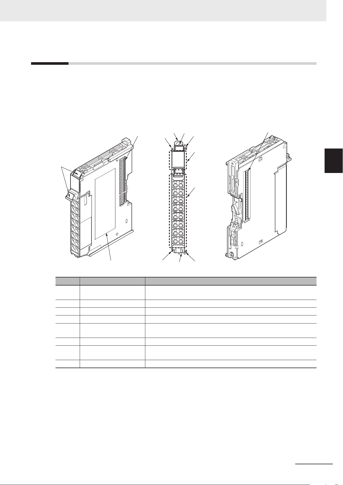
(A)
(H)
(B)
(B)
(C)
(G)
(F)
(C)
(C)
(C)
(D)
(E)
(E)
3 Configuration Units
3-4
NX Units
The NX Units perform I/O processing with connected external devices. The NX Units refers to NX-ser-
ies NX-££££££ Units.
Up to 32 NX Units can be connected to the CPU Unit.
The following is an example of NX Unit’s part names and functions.
For details on the part names and functions of NX Units, refer to the user’s manual for each NX Unit.
3-4 NX Units
3
Symbol Name Function
A Marker attachment location The locations where markers are attached. OMRON markers are pre-installed at
the factory. Y
B NX bus connector This connector is used to connect another Unit.
C Unit hookup guides These guides are used to connect two Units.
D DIN Track mounting hook This hook is used to mount the NX Unit to a DIN Track.
E Protrusions for removing the
Unit
F Indicators The indicators show the current operating status of the Unit.
G Terminal block The terminal block is used to connect external devices.
H Unit specifications The specifications of the Unit are given here.
The protrusions to hold when removing the Unit.
The number of terminals depends on the type of Unit.
ou can also install commercially available markers.
NX-series NX102 CPU Unit Hardware User’s Manual (W593)
3-17
Page 98
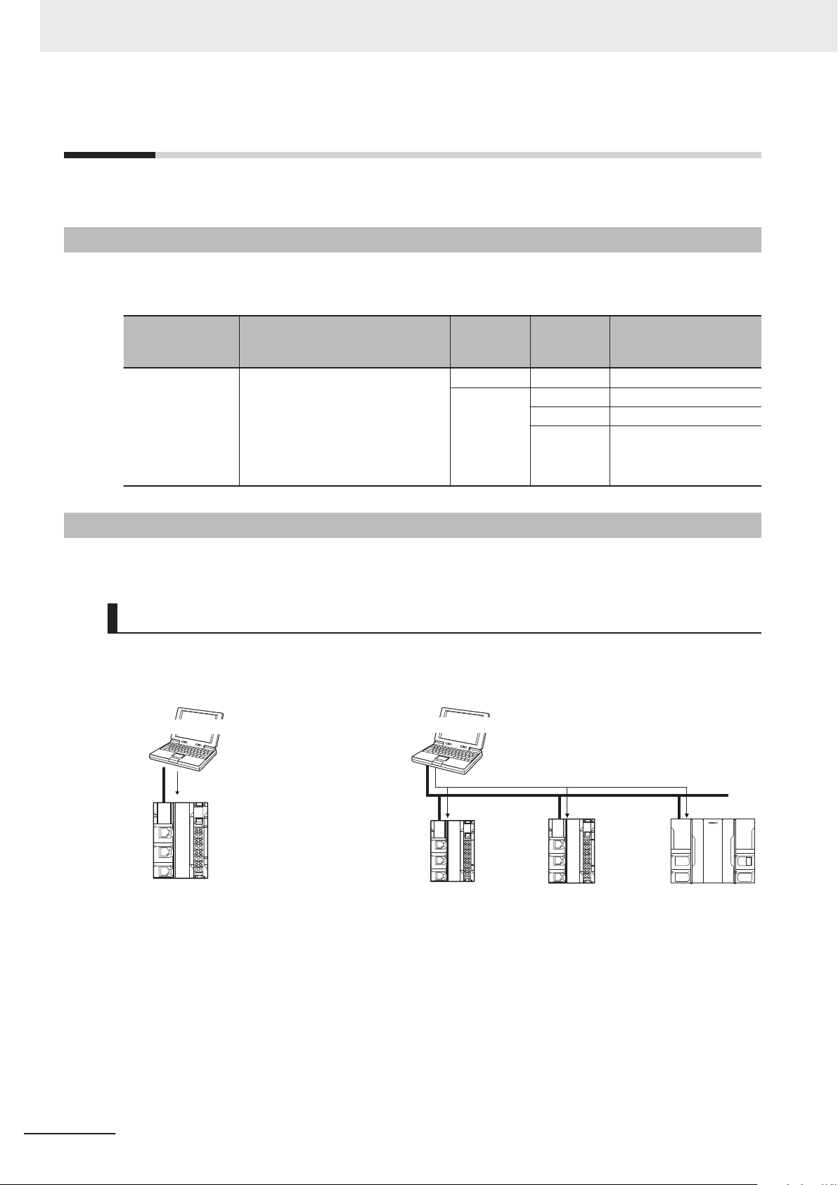
EtherNet/IP
Sysmac Studio
EtherNet/IP
Sysmac Studio
3 Configuration Units
3-5
3-5-1
3-5-2
Sysmac Studio
This section describes the models and connecting methods of the Sysmac Studio.
Model Numbers
The model numbers of the Sysmac Studio are given in the following table. The model numbers are
different for the media and licenses.
Number of
Product Configuration software Media
Sysmac Studio
Standard Edition
Sysmac Studio
The following Support Software is also
included.
Network Configurator
CX-Integrator
CX-Protocol
CX-Designer
Connection
DVD --- SYSMAC-SE200D
Licenses 1 SYSMAC-SE201L
user licens-
es
3 SYSMAC-SE203L
10 SYSMAC-SE210L
Model
With an NX102 CPU Unit, you can connect the Sysmac Studio online in the following ways.
Configuration
Connection with EtherNet/IP
l
• 1:1 Connection • 1:N Connection
• A direct connection is made from the Sys-
mac Studio. The IP address and connec-
tion device do not need to be specified.
*1
• You can make the connection whether or
not an Ethernet switch is used.
• Support for Auto-MDI enables the use of
cross cables or straight cables if a direct
connection is made.
*1.
With the NX102 CPU Unit, this is possible only when you connect the Unit to the built-in EtherNet/IP port
(Port 1).
Directly specify the IP address of the remote device.
3-18
NX-series NX102 CPU Unit Hardware User’s Manual (W593)
Page 99
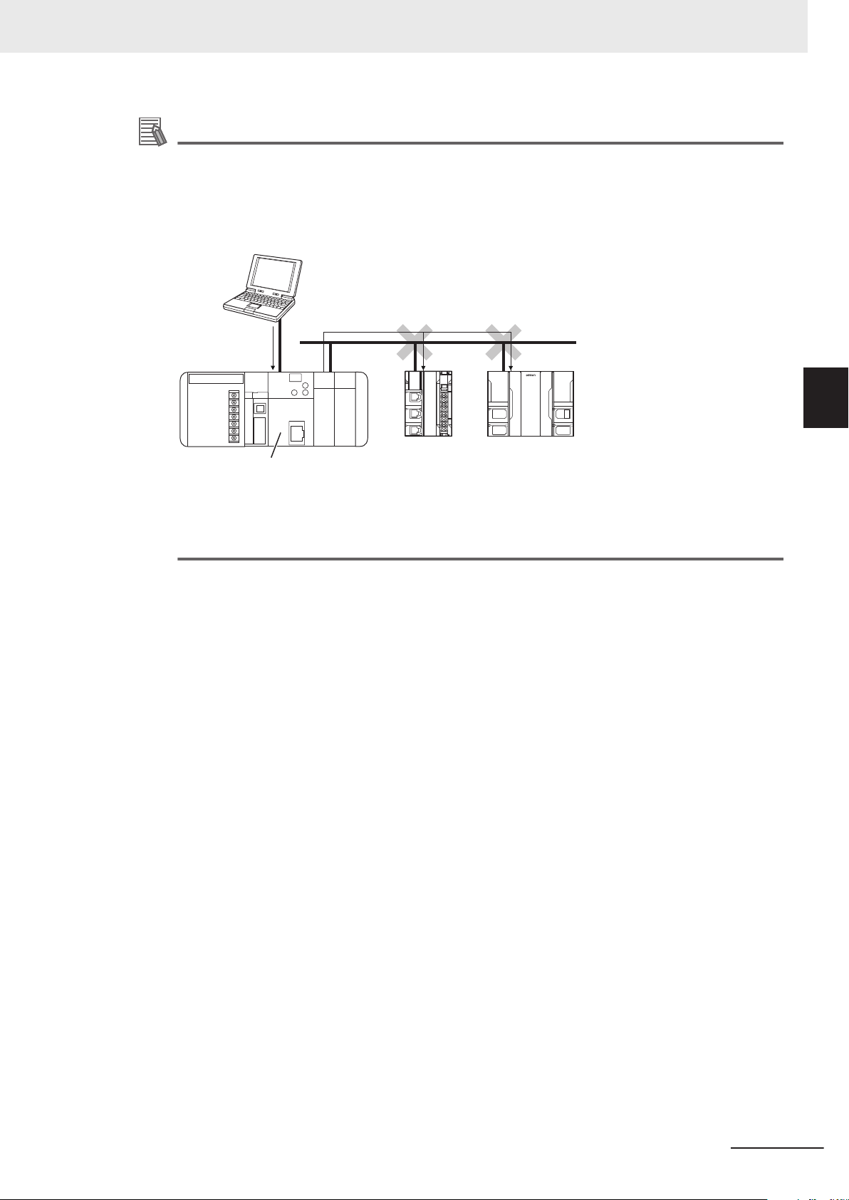
Sysmac Studio
USB
EtherNet/IP
CS1W-EIP21, CJ1W-EIP21, CJ2 Built-in EtherNet/IP port, or
CJ2M Built-in EtherNet/IP
port
3 Configuration Units
Additional Information
The Sysmac Studio cannot connect online to an NJ/NX-series CPU Unit in the following type of
configuration.
• If the built-in EtherNet/IP port is not used, you cannot connect to an NJ/NX-series CPU Unit
on an EtherNet/IP network.
Example: Connection to NJ/NX-series CPU Unit Routing through an EtherNet/IP Unit or Built-in
Port
3-5 Sysmac Studio
3
3-5-2 Connection
• You cannot route through any networks other than EtherNet/IP networks.
NX-series NX102 CPU Unit Hardware User’s Manual (W593)
3-19
Page 100

3 Configuration Units
3-20
NX-series NX102 CPU Unit Hardware User’s Manual (W593)
 Loading...