

Page 1
SJDE-@APA-OY
A
A
Junma Pulse servo drive
A new concept in drive simplicity
Save space, save time
• Ultra compact drive size reduces panel space
• Tuning-less technology, no gain parameters need to
be set
• Peak torque 300% of nominal for 3 seconds
• High response, high speed, high torque and high
accuracy
• Fully “Parameter-less” just plug and run
• Position resolution of 10,000 steps per revolution
Ratings
• 230 VAC Single-phase 100 W to 750 W (2.39 Nm)
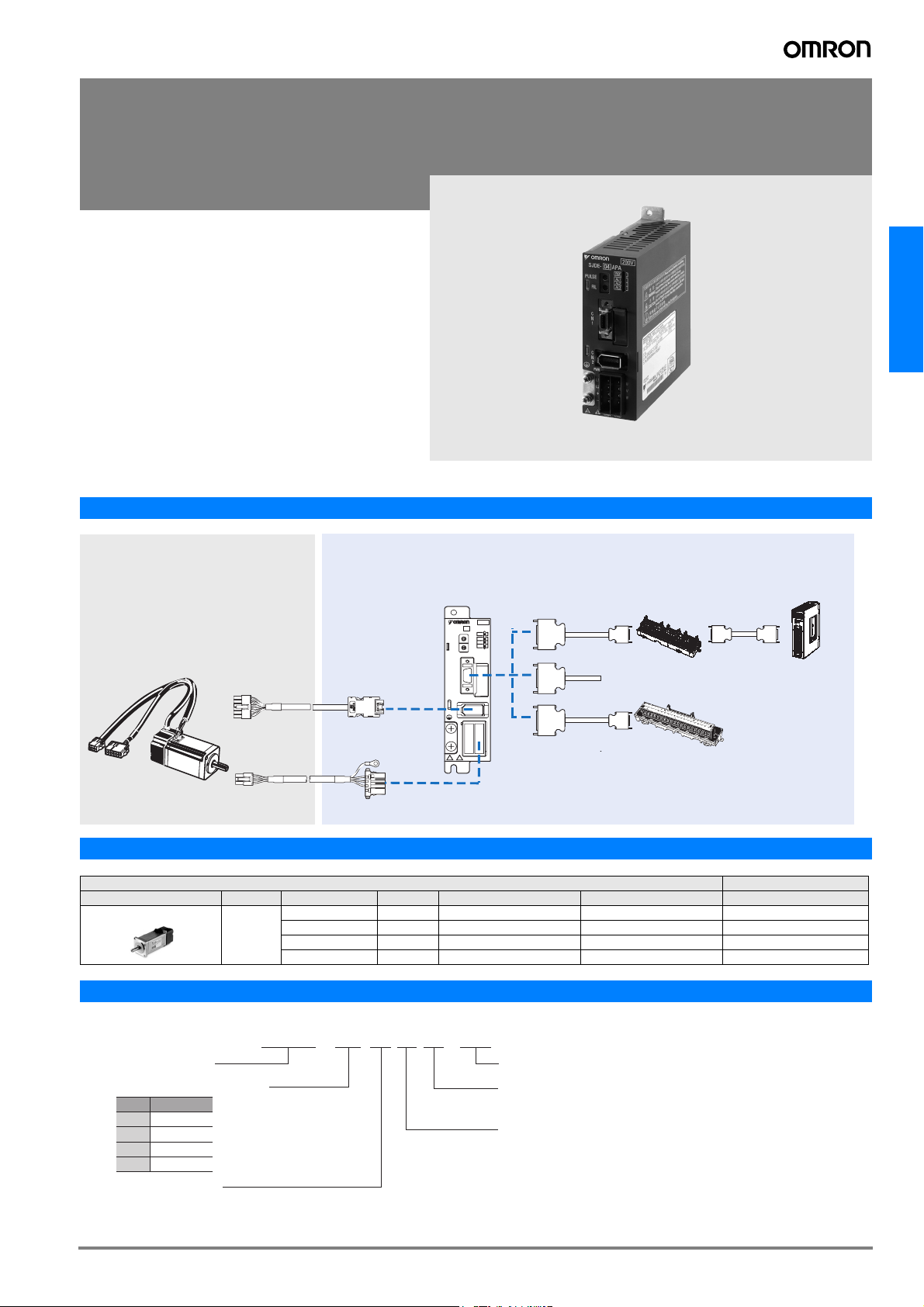
System Configuration
Junma PULSE Servo Drive Configuration
AC Servo systems
Junma Pulse
Servo Drive
200V
SJDE- 02 APA-OY
REF
D
C
B
E
A
F
9
0
8
1
AL1
7
PULSE
2
6
3
5
4
AL2
D
C
B
E
A
F
AL3
9
0
8
1
7
2
FIL
6
3
5
Junma Servo Motor
3,000 rpm
(100-750 W)
Encoder cable
Power cable
4
C
N
1
C
N
2
PWR
U
L1
V
L2
W
+
-
CNA CNB
Connector terminal block
Position control
unit
General purpose controller
(with pulse output)
Servomotor / Servo Drive Combination
Junma Servomotor Junma servo drive
-1
SJME- (3000 min
) 200 V 0.318 Nm 100 W SJME-01AMB41-OY SJME-01AMB4C-OY SJDE-01APA-OY
Voltage Rated Torque Capacity Model without brake Model with brake Pulse Control
0.637 Nm 200 W SJME-02AMB41-OY SJME-02AMB4C-OY SJDE-02APA-OY
1.27 Nm 400 W SJME-04AMB41-OY SJME-04AMB4C-OY SJDE-04APA-OY
2.39 Nm 750 W SJME-08AMB41-OY SJME-08AMB4C-OY SJDE-08APA-OY
Servo Drive Type Designation
SJDE - 02 A P A - OY
JUNMA servo drive
pplicable servomotor capacity
Output (W)
Code
100
01
200
02
400
04
750
08
Power supply voltage
: 200 VAC
OMRON YASKAWA Motion Control BV
Design revision
A: Standard
Control Interface specification
N: MECHATROLINK-II
P: Pulse train input
169Junma Pulse servo drive
Page 2
Servo Drive Specifications
Junma Pulse Servo Drives
Servo Drive Type SJDE- @ 01APA-OY 02APA-OY 04APA-OY 08APA-OY
Applicable servomotor SJME-@ 01A@ 02A@ 04A@ 08A@
Max. Applicable Motor capacity W 100 200 400 750
Continuous output current Arms 0.84 1.1 2.0 3.7
Max. output current Arms 2.5 3.3 6.0 11.1
Input power supply
(Main circuit and control circuit)
Control Method PWM control, sine wave current drive system
Feedback Analogue incremental encoder (10000 steps per revolution)
Allowable load inertia
*1
Usage / storage temperature 0 to +55° C / -20 to 70° C
Usage / storage humidity 90%RH or less (non-condensing)
Basic specifications
Altitude 1000 m or less above sea level
Vibration/shock Resistance 4.9m/s
Configuration Base mounted
Cooling method Forced cooling (built-in fan)
Approx. mass kg 0.5 1.0
Dynamic brake (DB) Operated at main power OFF, servo alarm, servo OFF.(OFF after motor stops; ON when motor power is off.)
Regenerative processing Optional (If the regenerated energy is too large, install a regenerative unit JUSP-RG08D)
LED display 5 (PWE, REF, AL1, AL2, AL3)
Reference filter Select one of eight levels with FIL switch
Protection Speed errors, overload, encoder errors, voltage errors, overcurrents, disablement of the built-in cooling fan,
Built-in functions
Input signal for reference
Designated pulse type and
pulse resolution with PULSE
switch.
Clear input signal Clears the positioning error when turned ON
I/O Signals
Servo ON input signal Turns the servomotor ON or OFF
Alarm output signal OFF if an alarm occurs. (Note: OFF for 2s when power is turned ON)
Brake output signal External signal to control brakes. Turn ON to release the brake
Positioning completed output signal ON if the current position is equal to the reference position ±10 pulses.External signal to control brakes.
Origin output signal ON if the motor is at the origin. (Width: 1/500 rev)
Voltage Single-phase, 200 to 230 VAC, + 10 to -15% (50/60 Hz)
Capacity KVA 0.40 0.75 1.2 2.2
kg⋅m
2
-4
0.6 × 10
2
(0.5G) / 19.6m/s2 (2G)
3.0 × 10
-4
5.0 × 10
-4
10.0 × 10
system errors
Pulse type Select one of the following signals:
1. CCW + CW
2. Sign + pulse train
3. CCW + CW (logic reversal)
4. Sign + pulse train (logic reversal)
Pulse resolution Select one of the following signals:
1. 1000 pulses/rev (Open collector/line driver) 75 kpps max.
2. 2500 pulses/rev (Open collector/line driver) 187.5 kpps max.
3. 5000 pulses/rev (Line driver) 375 kpps max.
4. 10000 pulses/rev (Line driver) 750 kpps max.
(Note:Use the pulse edge that changes the signal from OFF to ON)
-4
Note: *1. Value without external regeneration unit
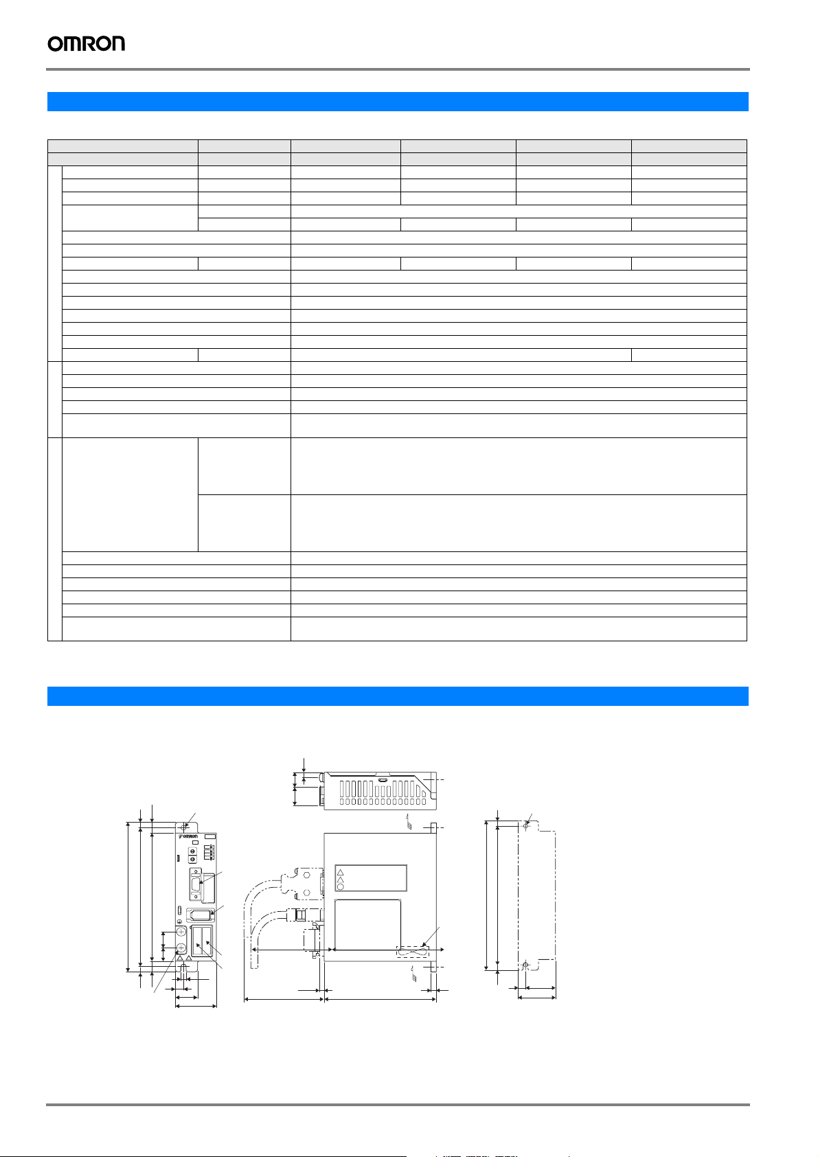
Dimensions
Junma pulse control servo drives
SJDE-01, 02APA-OY (200V, 100 to 200W)
15
12.5
4.5 dia.holes
SJDE- 02 APA-OY
D
C
B
E
A
F
9
0
8
1
7
PULSE
2
6
3
5
4
D
C
B
E
A
F
9
0
8
1
7
2
FIL
6
3
5
4
C
N
1
C
N
2
PWR
L1
L2
+
-
CNA CNB
4.5
7
19
35
200V
REF
AL1
AL2
AL3
CN1
CN2
U
V
W
CNB
CNA
(75)
10
5
130
120
140
(5)
(10)
Ground Terminal
2-M4 screws
(14)
(17)
(5)
(4.5)
AIR FLOW
AIR FLOW
105
Cooling fan
5
Mounting Hole Diagram
2-M4 screw holes
5
)
140
130 ± 0.5
Mounting pitch
(
(5)
(28)
7
35
Approx. mass : 0.5 kg
Units in mm
170 AC Servo Systems
Page 3

SJDE-04APA-OY (200V, 400W)
5
10
130
140
120
(5)
(10)
Ground Terminal
2-M4 screws
15
12.5
4.5 dia.holes
SJDE- 04 APA-OY
D
C
B
E
A
F
9
0
8
1
7
PULSE
2
6
3
5
4
D
C
B
E
A
F
9
0
8
1
7
2
FIL
6
3
5
4
C
N
1
C
N
2
PWR
L1
L2
+
-
CNA CNB
4.5
7
19
40
200V
REF
AL1
AL2
AL3
CN1
CN2
U
V
W
CNB
CNA
SJDE-08APA-OY (200V, 800W)
(75)
(14)(17)
(44)(17)
(5)
(4.5)
(35)
AIR FLOW
AIR FLOW
105
Cooling fan
5
Mounting Hole Diagram
5130 ± 0.5
)
140
Mounting pitch
(
(5)
7
2-M4 mounting holes
Visible outline
Approx. mass : 0.5 kg
(33)
40
AC Servo systems
Units in mm
17
4.5 dia.holes
SJDE- 08 APA-OY
D
C
B
E
A
F
9
0
8
1
7
PULSE
2
6
3
5
4
D
C
B
E
A
F
9
0
8
1
7
2
FIL
6
3
5
4
C
N
1
C
N
2
PWR
L1
L2
+
-
CNA CNB
4.5
70
200V
REF
AL1
AL2
AL3
CN1
CN2
U
V
W
CNB
CNA
140
130 5(5)
Ground Terminal
2-M4 screws
10(10) 120
12.5 15
14 30
Ordering Information
Junma Pulse Servo Drive Configuration
(Refer to servo motor chapter)
A
Junma Servo Motor
3,000 rpm
(100-750 W)
D
Encoder cable
Power cable
C
(75)
(4.5)
Filter
Junma Pulse
B
Servo Drive
PULSE
J
K
AIR FLOW
AIR FLOW
145
SJDE- 02 APA-OY
D
C
B
E
A
F
9
0
8
1
7
2
6
3
5
4
D
C
B
E
A
F
9
0
8
1
7
2
FIL
6
3
5
4
C
N
1
C
N
2
PWR
L1
L2
+
-
CNA CNB
200V
REF
AL1
AL2
AL3
U
V
W
Cooling fan
5
F
H
I
Mounting Hole Diagram
5
)
140
130 ± 0.5
Mounting pitch
(
(5)
141730
2-M4 mounting holes
Visible outline
Approx. mass : 1 kg
(13)
70
E
G
I
Connector terminal block
General purpose controller
(with pulse output)
Units in mm
Position control
unit
Junma Pulse servo drive 171
Page 4

Servomotors and Servo drives
Symbol Specifications A Servomotor model B Servo drive model
Voltage Encoder and Design Rated Torque Capacity Pulse Control
AB
1 Phase
200 VAC
Analogue Incremental
Encoder
Straight shaft with key
Without brake 0.318 Nm 100 W SJME-01AMB41-OY SJDE-01APA-OY
0.637 Nm 200 W SJME-02AMB41-OY SJDE-02APA-OY
1.27 Nm 400 W SJME-04AMB41-OY SJDE-04APA-OY
2.39 Nm 750 W SJME-08AMB41-OY SJDE-08APA-OY
With brake 0.318 Nm 100 W SJME-01AMB4C-OY SJDE-01APA-OY
0.637 Nm 200 W SJME-02AMB4C-OY SJDE-02APA-OY
1.27 Nm 400 W SJME-04AMB4C-OY SJDE-04APA-OY
2.39 Nm 750 W SJME-08AMB4C-OY SJDE-08APA-OY
Control cables (for CN1) Filters
Symbol Name Compatible units Model
E
F
G
H
I
Servo relay
unit
Cable to
servo drive
Cable to position
control unit
Control cable
Connector
terminal
block cable
Connector
terminal
block
Units: CS1W-NC113/133,
CJ1W-NC113/133,
C200HW-NC113
Units:
CS1W-NC213/233/413/433,
CJ1W-NC213/233/413/433,
C200HW-NC213/413
Units: CQM1H-PLB21 and
CQM1-CPU43-V1
Use with
CJ1M-CPU21/22/23
For the servo relay unit
XW2B-@@J6-@B,
XW2B-20J6-8A,
XW2B-40J6-9A
CQM1H-PLB21 and
CQM1-CPU43-V1
CS1W-NC113 and
C200HW-NC113
CS1W-NC213/413 and
C200HW-NC213/413
CS1W-NC133 0.5 m XW2Z-050J-A12
CS1W-NC233/433 0.5 m XW2Z-050J-A13
CJ1W-NC113 0.5 m XW2Z-050J-A16
CJ1W-NC213/413 0.5 m XW2Z-050J-A17
CJ1W-NC133 0.5 m XW2Z-050J-A20
CS1W-NC233/433 0.5 m XW2Z-050J-A21
CJ1M-CPU21/22/23 0.5 m XW2Z-050J-A26
For general-purpose controllers
For general-purpose
controllers
- XW2B-20J6-1B
(1 axis)
- XW2B-40J6-2B
(2 axes)
- XW2B-20J6-3B
(1 axis)
- XW2B-20J6-8A
(1 axis)
- XW2B-40J6-9A
(2 axes)
1 m XW2Z-100J-B17
2 m XW2Z-200J-B17
0.5 m XW2Z-050J-A3
1 m XW2Z-100J-A3
0.5 m XW2Z-050J-A8
1 m XW2Z-100J-A8
0.5 m XW2Z-050J-A9
1 m XW2Z-100J-A9
1 m XW2Z-100J-A12
1 m XW2Z-100J-A13
1 m XW2Z-100J-A16
1 m XW2Z-100J-A17
1 m XW2Z-100J-A20
1 m XW2Z-100J-A21
1 m XW2Z-100J-A26
1 m R7A-CPZ001S
or JZSP-CHI003-01
2 m R7A-CPZ002S
or JZSP-CHI003-02
3 m JZSP-CHI003-03
1 m XW2Z-100J-B19
2 m XW2Z-200J-B19
- XW2B-20G5
Symbol Applicable servo
J
drive
SJDE-01APA-OY
SJDE-02APA-OY
SJDE-04APA-OY
SJDE-08APA-OY 9A 1.7 mA R7A-FIZP109-BE
Rated
Leakage
current
current
5A 1.7 mA 250 VAC
Rated
voltage
1- phase
Filter model
R7A-FIZP105-BE
Regenerative Unit Model (Option)
Symbol Specifications Model (Omron) Model (Yaskawa)
K
External regenerative unit
(Optional)
R88A-RG08UA JUSP-RG08D
Connectors
Specification Model (Omron) Model (Yaskawa)
Control I/O connector (for CN1) R7A-CNA01R JZSP-CHI9-1
Power input connector (for CNB).
(Included in drive the box)
R7A-CNZ01P JZSP-CHG9-1
Power and encoder cables
Note: CD Refer to the Junma servo motor section for motor cables or connec-
tors selection
ALL DIMENSIONS SHOWN ARE IN MILLIMETERS.
To convert millimeters into inches, multiply by 0.03937. To convert grams into ounces, multiply by 0.03527.
Cat. No. I71E-EN-01
In the interest of product improvement, specifications are subject to change without notice.
172 AC Servo Systems
 Loading...