

Page 1
New Product
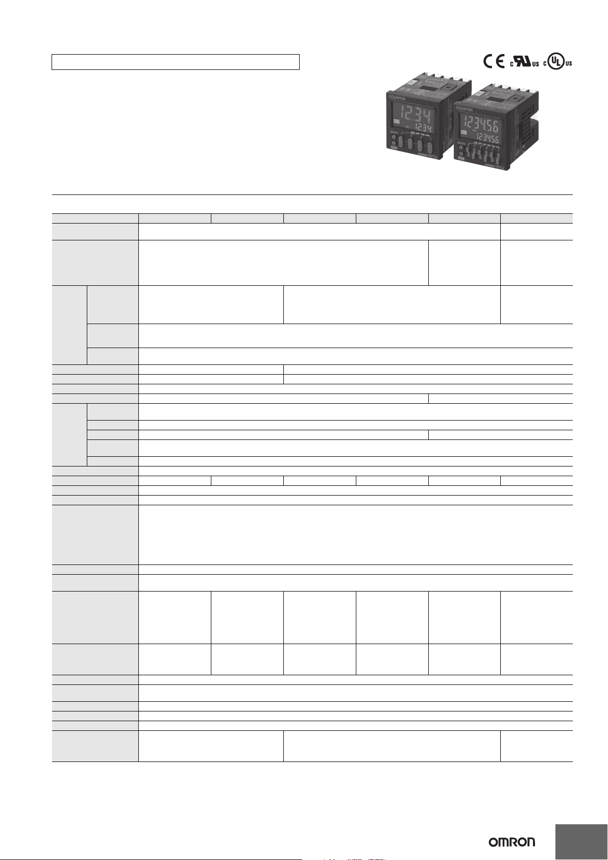
Multifunction Counter/Tachometer
H7CX-@-N
Ultra-compact Counter Provides More
Complete Functionality.
Basic Features
• Short body with depth of only 59 mm (for 12 to 24-VDC Models with Screw
Terminals).
• Better readability with character height of 12 mm on 4-digit models and 10 mm
on 6-digit models.
• The present value display characters can be switched between red, green, and
orange.
Safety and Reliability
• New set value limit and counter functions have been added.
Other Features
• Front Panel can be changed to white or light gray.
• Models with two independent tachometer inputs have been added to the series.
*1.For 100 to 240-VAC Models with Screw Terminals: 78 mm, Models with Sockets: 63.7 mm (case dimension).
*2.The H7CX-A11 and H7CX-R11 have only red characters.
*3.The Front Panel can be replaced with an optional Front Panel (except for Tachometer-only Models).
*1
*2
*3
Refer to Safety Precautions on page 52.
Features
Basic Features
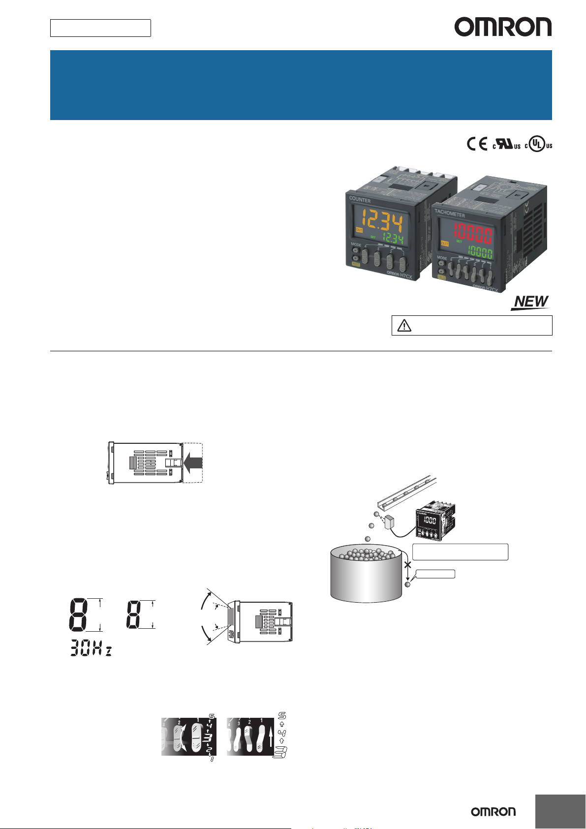
Ultra Short Body
The body depth has been greatly reduced. Helps in making thinner
control panels.
12 to 24-VDC Models with Screw Terminals: 59 mm
100 to 240-VAC Models with Screw Terminals: 78 mm*
Models with Sockets: 63.7 mm (case dimension)
* Power supply circuit and input circuits are isolated for safety and reliability.
New models
Easier to Read
For better readability, the character height for the present value
display is 12 mm on models with 4 digits, the largest class in the
industry. The wide viewing angle and brightness provide excellent
visibility. The number of display segments has also been increased to
make settings easier to understand, and the present value display
can be switched between red, green, and orange so that output status
can be seen from a distance.
Model with 4 Digits Model with 6 Digits
12 mm
(actual size)
(Display example)
Note: The display color can be switched on all models except for the
H7CX-A11 and H7CX-R11.
10 mm
(actual size)
Previous
models
Previous
New
models
models
Easy to read from the top, bottom,
and sides!
Safety and Reliability
Isolated Power Supply and Input Circuits
Power supply circuit and input circuits are isolated inside the Counter/
Tachometer. Previous non-isolated counters had wiring restrictions
and could be damaged if wired incorrectly. The H7CX removes these
worries.
Note: Except 12 to 24-VDC models.
Set Value Limit
You can set an upper limit for the set value to prevent unexpected
operation of output devices caused by setting mistakes.
Setting the upper limit of the set
value enables worry-free operation.
For 1,000 pieces
Output Counter
The output counter counts the number of times the output turns ON
(alarms can be displayed and the count can be monitored in
increments of 1,000 operations). This counter is useful in managing
the service life of the Counter/Tachometer or the load.
No overflow
The Easiest Operation
Operation is simplified by the
Up/Down Key for each digit
on 4-digit models and Up
Key for each digit on 6-digit
models.
Model with 4 Digits Model with 6 Digits
1
Page 2
H7CX-@-N
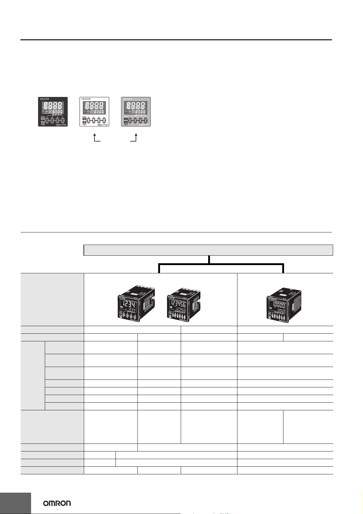
Other Features
The front color can be changed simply by
replacing the Front Panel.
The Front Panel can be replaced with an optional Front Panel (sold
separately) with a different color to match the installation site. Select
from black, white, and light gray (except for models with tachometer
function only).
Black
(Standard)
White
Only the Front
Panel can be
replaced.
Universal NPN/PNP Input
DC 2-wire sensors can be connected for a wide range of input
devices.
Waterproof, Dust-proof Structure (UL508 Type
4X and IP66)
Worry-free application is possible in locations subject to water.
Note: When the Y92S-29 Waterproof Packing is used.
Light gray
Key Protection
Select from any of seven protection patterns. Use the best one for the
application.
New Functions
Many useful functions have been added, including a Twin Counter
Mode and many tachometer functions to handle even more
applications.
New Tachometer Functions
• Control with two independent inputs (independent measurements,
differential, absolute ratio, and error ratio)
• Peak/bottom hold function
• Output hysteresis setting
• Output OFF delay
• Switching the measurement method (pulse cycle/pulse width)
• Startup time
• Auto-zero time
• Averaging method/Number of averaging times
• AMD-compatible Mode
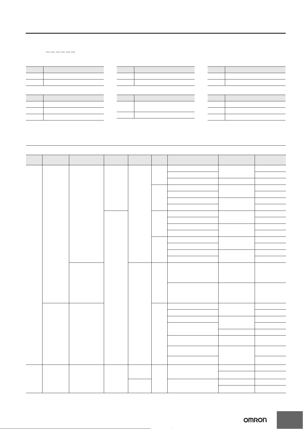
Model Number Structure
Model Configuration
H7CX Series
H7CX-A-series Multifunction Preset Counter H7CX-R-series Digital Tachometer
Model
Classification Preset counter Preset counter/tachometer Tachometer
Model H7CX-A@-N H7CX-A4W@-N H7CX-AW@-N/-AU@-N H7CX-R11@-N H7CX-R11W@-N
1-stage preset
counter
2-stage preset
counter
Function
Tachometer input No No
Settings 1-stage 2-stage 1-stage
External connections 11-pin socket Screw terminals 11-pin socket
Display color of present value Red Red, green, or orange Red
Display digits 4 or 6 digits 4 digits 6 digits 6 digits
*1. Set the tachometer input mode from the function setting mode to switch to the tachometer function.
Total and preset
counter
Batch counter No Yes Yes No
Dual counter No Yes Yes No
Twin counter No Yes Yes No
Tachometer No No Yes
Yes Yes Yes No
No Yes Yes No
Yes Yes Yes No
*1
Yes
1 input or 2 inputs
(independent
measurements, differential,
absolute ratio value, and
error ratio value)
Yes
1 input
Yes
Yes
2 inputs (independent
measurement) only
2
Page 3
Model Number Legend (Not all possible combinations of functions are available.)
H7CX-@@@@@@-N
123 456
1. Type 2. External connections 3. Digits
Symbol Meaning
A Standard type
R Tachometer
4. Settings
Symbol Meaning
None 1-stage setting
U Factory-set to 1-stage setting
W Factory-set to 2-stage setting*
* The H7CX-R11W@ is a 1-stage (2 inputs and outputs)
rather than a 2-stage Counter.
Symbol Meaning
None Screw terminals
11 11-pin socket
Symbol Meaning
None 6 digits
4 4 digits
5. Output type 6. Supply voltage
Symbol Meaning
None
Contact output or contact output +
transistor output
S Transistor output
Symbol Meaning
None 100 to 240 VAC at 50/60 Hz
D 12 to 24 VDC
D1 12 to 24 VDC/24 VAC at 50/60 Hz
Ordering Information
List of Models
Type Classification Configuration
• 1-stage preset
counter
• Total and preset
counter
Preset counter
H7CX-A
Series
H7CX-R
Series
Preset counter/
Tachometer
Tachometer • Tachometer 11-pin socket
• 1-stage preset
counter
• 2-stage preset
counter
• Total and preset
counter
• Batch counter
• Dual counter
• Twin counter
• 1-stage preset
counter
• 2-stage preset
counter
• Total and preset
counter
• Batch counter
• Dual counter
• Twin counter
• Tachometer
External
connections
11-pin socket
Screw
terminals
Settings
1-stage
2-stage
1-stage
(1 input and
output)
1-stage
(2 inputs and
outputs)
Note: 1. The functions that are provided depend on the model. Check detailed specifications before ordering.
2. Refer to page page 37 and later for information on H7CX-R Tachometers.
Display
digits
4 digits
6 digits
4 digits
6 digits
4 digits
6 digits
6 digits
Outputs
Contact output (SPDT)
Transistor output (SPST) H7CX-A114S-N
Contact output (SPDT) 12 to 24 VDC/24 VAC H7CX-A114D1-N
Contact output (SPDT)
Transistor output (SPST) H7CX-A11S-N
Contact output (SPDT)
Transistor output (SPST) H7CX-A11SD1-N
Contact output (SPDT)
Transistor output (SPST) H7CX-A4S-N
Contact output (SPDT)
Transistor output (SPST) H7CX-A4SD-N
Contact output (SPDT)
Transistor output (SPST) H7CX-AS-N
Contact output (SPDT)
Transistor output (SPST) H7CX-ASD-N
Contact output (SPST + SPDT) 100 to 240 VAC H7CX-A4W-N
Transistor output (DPST) 12 to 24 VDC H7CX-A4WSD-N
Contact output (SPST + SPDT)
Transistor output (DPST) H7CX-AWS-N
Contact output (SPST + SPDT)
Transistor output (DPST)
Contact output (SPDT) +
Transistor output (SPST)
Contact output (SPDT) +
Transistor output (SPST)
Transistor output (DPST) H7CX-AUSD1-N
Contact output (SPDT)
Contact output (SPDT + SPST)
100 to 240 VAC
100 to 240 VAC
12 to 24 VDC/24 VAC
100 to 240 VAC
12 to 24 VDC
100 to 240 VAC
12 to 24 VDC
100 to 240 VAC
12 to 24 VDC/24 VAC
12 to 24 VDC H7CX-AWSD-N
100 to 240 VAC H7CX-AU-N
12 to 24 VDC/24 VAC
100 to 240 VAC H7CX-R11-N
12 to 24 VDC/24 VAC H7CX-R11D1-N
100 to 240 VAC H7CX-R11W-N
12 to 24 VDC/24 VAC H7CX-R11WD1-N
Power supply
voltage
H7CX-@-N
Model
H7CX-A114-N
H7CX-A11-N
H7CX-A11D1-N
H7CX-A4-N
H7CX-A4D-N
H7CX-A-N
H7CX-AD-N
H7CX-AW-N
H7CX-AWD1-N
H7CX-AWSD1-N
H7CX-AUD1-N
3
Page 4
H7CX-@-N
Accessories (Order Separately)
Front Panels (Replacement Part)
Model Color Applicable Counters Page
Y92P-CXC4G Light gray (5Y7/1) 4-digit Counter
Y92P-CXC4S White (5Y9.2/0.5)
Y92P-CXC4B Black (N1.5)
Y92P-CXC6G Light gray (5Y7/1) 6-digit Counter
Y92P-CXC6S White (5Y9.2/0.5)
Y92P-CXC6B Black (N1.5)
Note: 1. You can change the color of the Front Panel when mounting the Counter. The Counter is shipped with a black (N1.5) Front Panel.
2. "COUNTER" is printed on the front of Replacement Front Panels.
Soft Cover
Model Remarks Page
Y92A-48F1 --- 12
Hard Cover
Model Remarks Page
Y92A-48 --- 12
Flush Mounting Adapter
Model Remarks Page
Y92F-30
Y92F-45
Included with models with screw
terminals.
Use this Adapter to install the Counter/
Tachometer in a cutout previously made
for a DIN 72 × 72 mm device (panel
cutout: 68 × 68 mm).
12
12
Waterproof Packing
Model Remarks Page
Y92S-29
Included with models with screw
terminals.
12
Connection Sockets
Connectable
Model Classification
P2CF-11 Front-connecting Socket
P2CF-11-E
P3GA-11 Back-connecting Sockets
Front-connecting Socket (Finger-safe
Type)
Counter/
Tachometers
H7CX-@11@-N
Terminal Covers for P3GA-11 Back-connecting Socket
Model Remarks Page
Y92A-48G --- 13
Remarks Page
---
Round crimp terminals cannot be used on
Finger-safe Sockets.
Use forked crimp terminals.
A Y92A-48G Terminal Cover can be used
with the Socket to create a finger-safe
construction.
13
4
Page 5
H7CX-A@-N
H7CX-A@-N Multifunction Preset Counter
• Easy to check the output status from a long distance with changing
display colors
*1
(red, green, and orange).
• Includes total and preset counter, batch counter, dual counter, twin
counter, and tachometer.
*1. Not supported by the H7CX-A11@-N.
*2. The functions that can be selected depend on the model.
*2
Specifications
Ratings
Item Models H7CX-A114@-N H7CX-A11@-N H7CX-A4@-N H7CX-A@-N H7CX-A4W@-N H7CX-AW@-N/-AU@-N
Classification Preset counter
1-stage/2-stage preset
counter, total and preset
Configuration 1-stage preset counter, 1-stage preset counter with total counter (selectable)*1
Power supply
voltage*2
Ratings
Mounting method Flush mounting or surface mounting Flush mounting
External connections 11-pin socket Screw terminals
Degree of protection IEC IP66, UL508 Type 4X (indoors) for panel surface only and only when Y92S-29 Waterproof Packing is used.
Input signals CP1, CP2, reset, and total reset CP1, CP2, reset 1, and reset 2
Counter
Tachometer Refer to the separate table for tachometer function ratings.
Prescaling function Yes (0.001 to 9.999) Yes (0.001 to 99.999) Yes (0.001 to 9.999) Yes (0.001 to 99.999) Yes (0.001 to 9.999) Yes (0.001 to 99.999)
Decimal point adjustment Yes (rightmost 3 digits)
Sensor waiting time 290 ms max. (Control output is turned OFF and no input is accepted during sensor waiting time.)
Input method
External power supply 12 VDC (±10%), 100 mA (except for H7CX-A@D models) Refer to Precautions for Correct Use on page page 53 for details.
Control output
Display*4
Digits
Memory backup EEPROM (overwrites: 100,000 times min.) that can store data for 10 years min.
Operating temperature
range
Storage temperature range −25 to 70°C (with no icing or condensation)
Operating humidity range 25% to 85%
Case color Black (N1.5) (Optional Front Panels are available to change the Front Panel color to light gray or white.)
Attachments --- Flush mounting adapter, waterproof packing, terminal cover
*1. 1-stage preset counter and total counter functionality.
*2. Do not use the output from an inverter as the power supply.The ripple must be 20% maximum for DC power.
*3. A response of 10 kHz is possible if the response speed is 5 kHz and the 1-stage preset counter input mode is increment, decrement, or increment/
*4. The display is lit only when the power is ON. Nothing is displayed when power is OFF.
Operating voltage fluctuation
range
Power consumption
Maximum
counting speed
Input mode Increment, decrement, increment/decrement (UP/DOWN A (command input), UP/DOWN B (individual inputs), or UP/DOWN C (quadrature inputs))
Output mode N, F, C, R, K-1, P, Q, A, K-2, D, and L. N, F, C, R, K-1, P, Q, A, K-2, D, L, and H.
One-shot output time
Reset system External (minimum reset signal width: 1 ms or 20 ms, selectable), manual, and automatic reset (internal according to C, R, P, and Q mode operation)
decrement (command input).
• 100 to 240 VAC, 50/60 Hz
• 24 VAC, 50/60 Hz or 12 to 24 VDC
85% to 110% of rated supply voltage (12 to 24 VDC: 90% to 110%)
Approx. 9.4 VA at 100 to 240 VAC, Approx. 7.2 VA/4.7 W at 24 VAC/12 to 24 VDC, Approx. 3.7 W at 12 to 24 VDC
30 Hz or 5 kHz (switchable) (ON/OFF ratio 1:1)*3
*Common setting for CP1 and CP2
0.01 to 99.99 s
No-voltage inputs:
ON impedance: 1 kΩ max. (Leakage current: 12 mA at 0 Ω)
ON residual voltage: 3 V max.
OFF impedance: 100 kΩ min.
Voltage input:
High (logic) level: 4.5 to 30 VDC
Low (logic) level: 0 to 2 VDC (Input resistance: approx. 4.7 kΩ)
No-voltage input/voltage input (switchable)
• Contact output: 3 A at 250 VAC/30 VDC, resistive load (cosφ=1), Minimum applied load: 10 mA at 5 VDC (failure level: P, reference value)
• Transistor output: NPN open collector, 100 mA at 30 VDC, Residual voltage: 1.5 VDC max. (approx. 1 V), Leakage current: 0.1 mA max.
7-segment, negative
transmissive LCD
Character height
Count value: 12 mm
(red)
Set value: 6 mm (green)
4 digits
−999 to 9999
(−3 digits to +4 digits)
−10 to 55°C (−10 to 50°C if Counter/Tachometers are mounted side by side) (with no icing or condensation)
7-segment, negative
transmissive LCD
Character height
Count value: 10 mm
(red)
Set value: 6 mm (green)
6 digits
−99999 to 999999
(−5 digits to +6 digits)
• 100 to 240 VAC, 50/60 Hz
•12 to 24 VDC
7-segment, negative
transmissive LCD
Character height
Count value: 12 mm
(red, green, or orange
selectable)
Set value: 6 mm (green)
4 digits
−999 to 9999
(−3 digits to +4 digits)
7-segment, negative
transmissive LCD
Character height
Count value: 10 mm
(red, green, or orange
selectable)
Set value: 6 mm (green)
6 digits
−99999 to 999999
(−5 digits to +6 digits)
counter*1, batch
counter, dual counter,
and twin counter
(selectable)
7-segment, negative
transmissive LCD
Character height
Count value: 12 mm
(red, green, or orange
selectable)
Set value: 6 mm (green)
4 digits
−999 to 9999
(−3 digits to +4 digits)
Preset counter/
tachometer
1-stage/2-stage preset
counter, total and preset
counter*1, batch
counter, dual counter,
twin counter, and
tachometer (selectable)
• 100 to 240 VAC at 50/
60 Hz
• 24 VAC at 50/60 Hz or
12 to 24 VDC
• 12 to 24 VDC
7-segment, negative
transmissive LCD
Character height
Count value: 10 mm
(red, green, or orange
selectable)
Set value: 6 mm (green)
6 digits
−99999 to 999999
(−5 digits to +6 digits),
tachometer: 0 to 999999
Flush mounting adapter,
waterproof packing,
terminal cover, label for
DIP switch settings
5
Page 6
H7CX-A@-N
)
Tachometer Function Ratings
Model
H7CX-A114@-N
H7CX-A11@-N
H7CX-A4@-N
Item
Input mode
Pulse measurement method Periodic measurement Pulse width measurement
Maximum counting speed 30 Hz
Minimum input signal width --- --- 30 ms
Measuring ranges 0.01 to 30.00 Hz
Sampling period 200 ms min.
Measuring accuracy ±0.1% FS ±1 digit max. (at 23 ±5°C)
Output mode
Auto-zero time 0.1 to 999.9s
Startup time 0.0 to 99.9s
Averaging Simple averaging/moving averaging selectable, Processing: OFF, 2, 4, 8, or 16 times
Hold input Minimum input signal width: 20 ms
* An input OFF time of at least 20 ms is required.
H7CX-A@-N
H7CX-A4W@-N
No tachometer
functionality
Selectable from independent measurements for 1 or 2 inputs, differential input for 2 inputs, absolute ratio for 2 inputs, and
error ratio for 2 inputs.
1-input mode: 10 kHz
Other modes: 5 kHz
1-input mode: 0.01 to 10 kHz,
Other modes: 0.01 to 5 kHz
200 ms min. or continuous
selectable (minimum interval of 10
ms)
Input mode:
Not 2-input independent measurement: HI-LO, AREA, HI-HI, LO-LO
2-input independent measurement: HI-HI, LO-LO
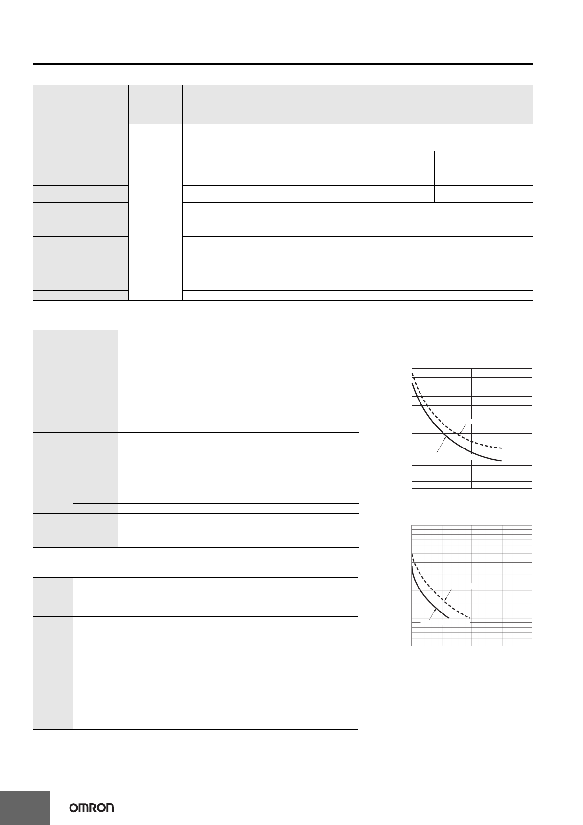
Characteristics
Insulation resistance
Dielectric strength
Impulse withstand voltage
Noise immunity
Static immunity
Vibration
resistance
Shock resistance
Life expectancy
Weight Approx. 130 g (Counter only)
* Refer to the Life-test Curve.
Destruction 10 to 55 Hz with 0.75-mm single amplitude each in three directions for 2 h each
Malfunction 10 to 55 Hz with 0.35-mm single amplitude each in three directions for 10 min each
Destruction 300 m/s2 each in three directions
Malfunction 100 m/s2 each in three directions
100 MΩ min. (at 500 VDC) between current-carrying terminals and exposed non-
current-carrying metal parts, and between non-continuous contacts
2,000 VAC, 50/60 Hz for 1 min between current-carrying metal parts and noncurrent-carrying metal parts
2,000 VAC, 50/60 Hz for 1 min between power supply and input circuit for all models
except H7CX-@D@ (1,000 VAC for 24 VAC/12 to 24 VDC)
1,000 VAC (for H7CX-@SD@), 50/60 Hz for 1 min between control output, power
supply, and input circuit (2,000 VAC for models other than H7CX-@SD@)
1,000 VAC, 50/60 Hz for 1 min between non-continuous contacts
3.0 kV between power terminals (1.0 kV for models with 24 VAC/12 to 24 VDC or 12
to 24 VDC)
4.5 kV between current-carrying terminals and exposed non-current-carrying metal
parts (1.5 kV for models with 24 VAC/12 to 24 VDC or 12 to 24 VDC)
±1.5 kV between power terminals (±480 V for models with 12 to 24 VDC)
±600 V between input terminals
Square-wave noise by noise simulator (pulse width: 100 ns/1 µs, 1-ns rise)
Malfunction: 8 kV
Destruction: 15 kV
Mechanical: 10,000,000 operations min.
Electrical: 100,000 operations min. (3 A at 250 VAC, resistive load, ambient
temperature condition: 23°C)*
Applicable Standards
Approved
safety
standards
EMC
* The following safety standards apply to models with sockets (H7CX-A11@ or H7CX-A114@).
cUL (Listing): Applicable when an OMRON P2CF(-E) Socket is used.
cUR (Recognition): Applicable when any other socket is used.
cULus (or cURus): UL508/CSA C22.2 No. 14*
EN 61010-1 (IEC 61010-1): Pollution degree 2/overvoltage category II
B300 PILOT DUTY
1/4 HP 120 VAC, 1/3 HP, 240 VAC, 3 A resistive load
VDE0106/P100 (finger protection)
(EMI) EN61326
Emission Enclosure: EN 55011 Group 1 class A
Emission AC mains: EN 55011 Group 1 class A
(EMS) EN61326
Immunity ESD: EN 61000-4-2: 4 kV contact discharge;
Immunity RF-interference: EN 61000-4-3: 10 V/m (Amplitude-modulated, 80 MHz to 1
Immunity Conducted Disturbance: EN 61000-4-6: 10 V (0.15 to 80 MHz)
Immunity Burst: EN 61000-4-4: 2 kV power-line;
Immunity Surge: EN 61000-4-5: 1 kV line to lines (power and output lines);
Immunity Voltage Dip/Interruption: EN 61000-4-11: 0.5 cycle, 100% (rated voltage)
8 kV air discharge
GHz);
10 V/m (Pulse-modulated, 900 MHz ±5 MHz)
1 kV I/O signal-line
2 kV line to ground (power and output lines)
H7CX-AW@-N/-AU@-N
30 Hz
0.030 to 999999 s
Continuous (minimum interval of 10 ms)
Life-test Curve (Reference
Values)
A current of 0.15 A max. can be switched at 125
VDC (cosφ=1) and current of 0.1 A max. can be
switched if L/R=7 ms. In both cases, a life of
100,000 operations can be expected.
*1
Resistive load
)
1,000
3
10
×
700
500
300
No. of operations (
250 VAC (cosφ=1)
100
70
50
01 2 34
Inductive load
)
1,000
3
10
×
700
500
300
No. of operations (
100
250 VAC (cosφ=1)
70
50
01 2 34
1-input mode: 10 kHz
Other modes: 5 kHz
1-input mode: 0.2 ms
Other modes: 0.4 ms*
1-input mode: 0.0002 to 99999 s
Other modes: 0.0004 to 99999 s
30 VDC (cosφ=1)
Load current (A
30 VDC (L/R=7 ms)
Load current (A)
6
Page 7
H7CX-A@-N
I/O Functions
Using as a Counter
CP1, CP2
Inputs
Reset/reset 1
Total reset or reset 2 The reset function depends on the selected configuration*3.
Outputs OUT1, OUT2 Outputs signals according to the specified output mode when a set value is reached.
*1. For information on operation of I/O functions, refer to pages page 22 to page 25.
*2. In increment mode or increment/decrement mode, the present value returns to 0; in decrement mode, the present value returns to the set value with 1-stage models,
and returns to set value 2 with 2-stage models.
*3. Reset operates as described in the following table. (The reset indicator will not be lit.)
Configuration Reset operation
1-stage/2-stage
preset counter
Total and preset
counter
Batch counter
Dual counter
Twin counter • Resets the CP2 present value.
• The following table shows the delay from when the reset signal is input until the output is turned OFF. (Reference values)
Minimum reset signal width Output delay time
1 ms 0.8 to 1.2 ms
20 ms 15 to 25 ms
*1
(1) In general (except for Dual Counter Mode)
• Reads counting signals.
• Increment, decrement, command, individual, and quadrature inputs accepted.
(2) When used as a dual counter or twin counter
• Reads CP1 count signals with CP1 input and CP2 count signals with CP2 input.
• Increment signals can be input.
(1) In general (except for Dual Counter Mode)
• Resets present value and outputs (OUT2 when using the batch counter)*2.
• Counting cannot be performed during reset/reset 1 input.
• Reset indicator is lit while reset input is ON.
(2) When used as a dual counter or twin counter.
• Resets the CP1 present value (to 0).
• Counting for CP1 input cannot be performed while the reset 1 input is ON.
• The reset indicator is lit while the reset 1 input is ON.
Does not operate (not used).
• Resets the total count value.
• The total count value is held at 0 while the total reset input is ON.
• Resets the batch count value and batch output (OUT1).
• The batch count value is held at 0 while the reset 2 input is ON.
• Resets the CP2 present value.
• Counting for CP2 input cannot be performed while the reset 2 input is ON.
Operating Procedures (Tachometer Function)
CP1, CP2 Reads counting signals. (The CP2 input can be used when the input mode is not 1-input mode.)
Inputs
Outputs OUT1, OUT2 Outputs signals according to the specified output mode when a set value is reached.
Reset/reset 1
• Holds the measurement value and outputs. (The reset 2 input can be used when the input mode
is 2-input independent measurement.)
• The reset indicator is lit when the value is being held.
7
Page 8
H7CX-A@-N
t
t
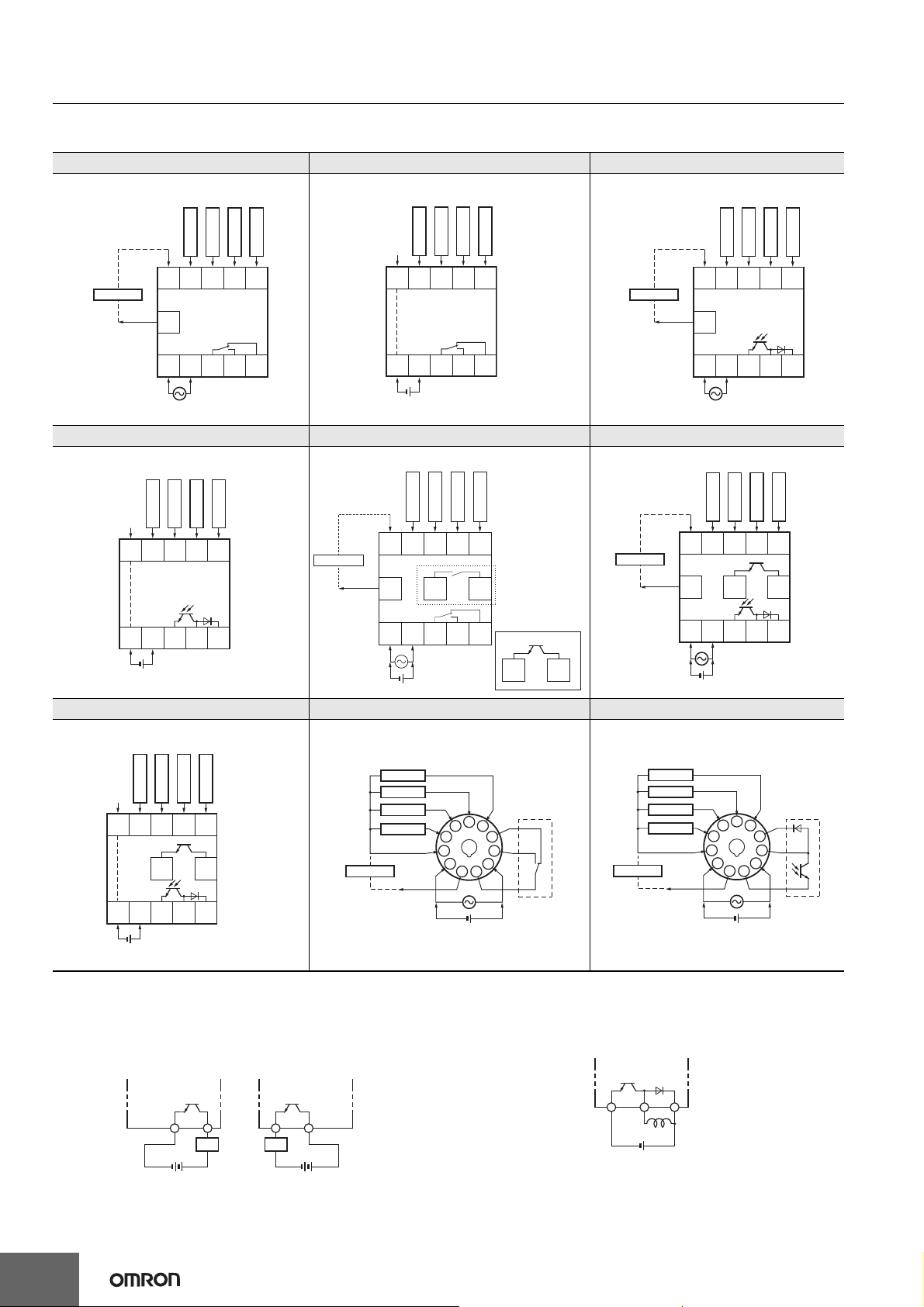
Connections
Terminal Arrangement
Confirm that the power supply meets specifications before use.
H7CX-A-N/-A4-N H7CX-AD-N/-A4D-N H7CX-AS-N/-A4S-N
1-stage Contact Output 1-stage Contact Output
1-stage Transistor Output
Reset
(+)
CP2
OUT
CP1
Total reset
(−)
Sensor
(+)
12 VDC
External
power supply
0 V
678910
11
12345
(−)
Sensor
(+)
12 VDC
External
power supply
CP1
CP2
Reset
0 V
678910
11
12345
OUT
Total reset
0 V
678910
12345
(−)
Terminals 1 and 6 are connected internally.
H7CX-ASD-N/-A4SD-N H7CX-AW-N/-A4W-N/-AWD1-N/-AU-N/-AUD1-N H7CX-AWS-N/-AWSD1-N/-AUSD1-N
1-stage Transistor Output
CP1
CP2
Reset
0 V
678910
12345
(+)(−)
Terminals 1 and 6 are connected internally.
Total reset
OUT
2-stage Contact Output 2-stage Transistor Output
CP1
(−)
Sensor
(+)
12 VDC
External
power supply
CP2
Reset 1
0 V
678910
11 12 13
12345
OUT2
(+)(−)
Reset 2
1
*
OUT1
1: “-AU@” Models
*
12 13
(−)
Sensor
(+)
12 VDC
External
power supply
*
Reset 1
0 V
678910
11 12 13
12345
(+)(−)
H7CX-AWSD-N/-A4WSD-N H7CX-A11-N/-A114-N/-A11D1-N/-A114D1-N H7CX-A11S-N/-A114S-N/-A11SD1-N
2-stage Transistor Output
1-stage Contact Output 1-stage Transistor Output
Reset
CP2
CP2
OUT2
OUT
CP1
CP1
Total reset
Reset 2
OUT1
CP1
CP2
Reset 1
0 V
678910
12 13
12345
(+)(−)
OUT2
Reset 2
OUT1
(−)
Sensor
(+)
Total reset
External
power supply
Terminals 1 and 6 are connected internally.
Transistor Output
• The transistor output of the H7CX is isolated from the internal
circuitry by a photocoupler, so the transistor output can be used as
both NPN and PNP output.
NPN Output PNP Output
Load
+
Power for load
+
Power for load
Load
Reset
CP1
CP2
12 VDC
0 V
Reset
CP1
(−)
Sensor
(+)
CP2
Total reset
0 V
12 VDC
External
power supply
6
5
7
4
3
8
9
2
10
1
11
(+)(−)
Internal circui
6
5
7
4
3
8
9
2
10
1
11
OUT
(+)
(−)
• The diode connected to the collector of the output transistor is used
to absorb inverted voltage that is generated when an inductive load
is connected to the H7CX.
Counter
Inductive
load
+
Power for load
Internal circui
OUT
8
Page 9
H7CX-A@-N
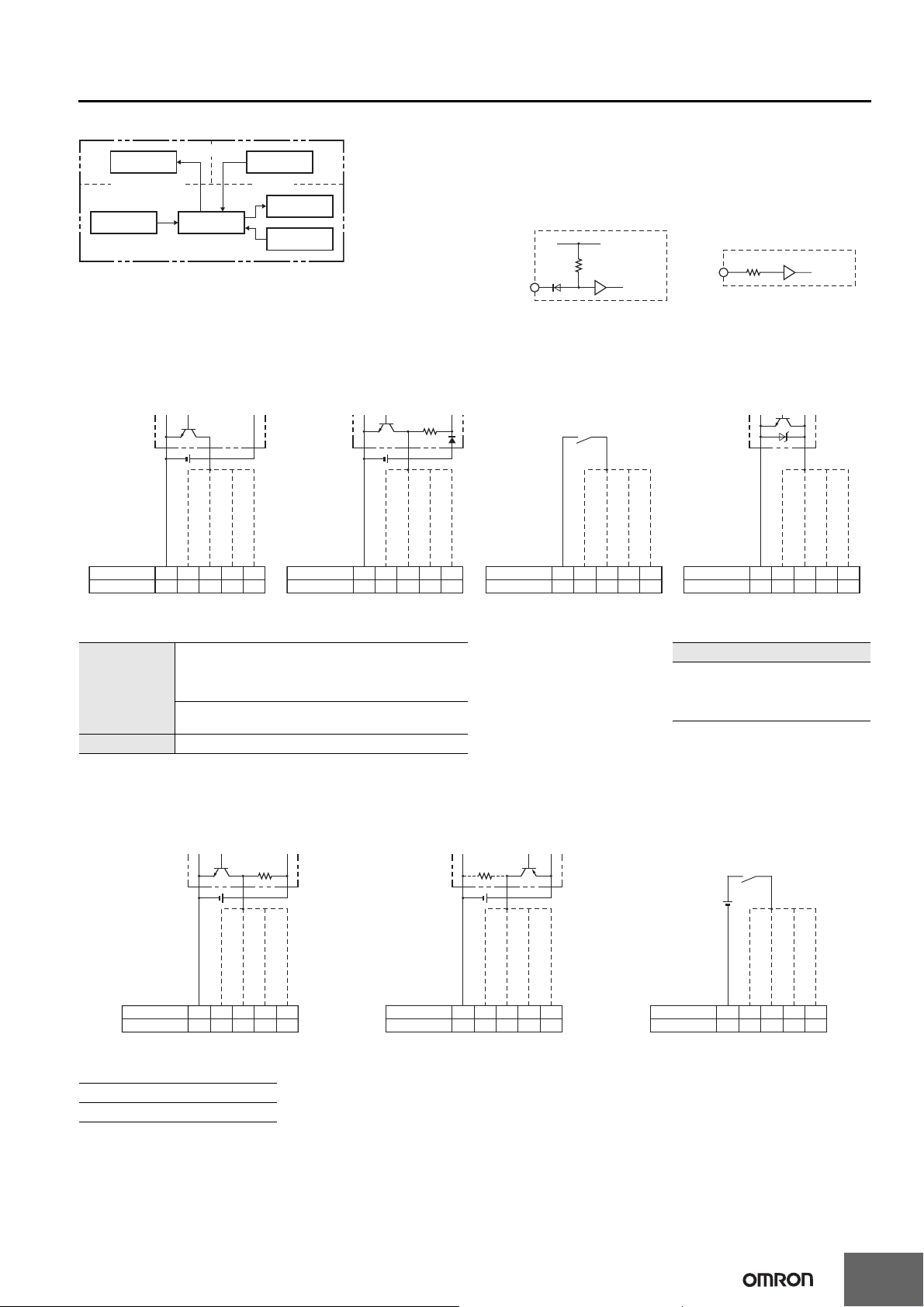
Block Diagram
Output circuit
(Basic insulation)
Input circuits
(Basic insulation)
Internal
control circuit
Note: All models except for H7CX-@D-N have basic insulation.
Power supply
circuit
(See note.)
Display circuit
Key switch
circuit
Input Circuits
CP1, CP2, Reset/Reset 1, and Total Reset/Reset 2
Input
No-voltage Inputs
(NPN Inputs)
+14V
1 kΩ
IN
Internal
circuit
Voltage Inputs (PNP Inputs)
Approx. 4.7 kΩ
IN
Input Connections
The inputs of the H7CX-@-N are no-voltage (short-circuit or open) inputs or voltage inputs.
No-voltage Inputs (NPN Inputs)
Open Collector Voltage Output Contact Input DC Two-wire Sensor
PLC or
sensor
0 V for inputs
Reset/reset 1 input
H7CX-A@
H7CX-A11@
Note: Operates with transistor ON.
678910
37564
CP2 input
CP1 input
Total reset/reset 2 input
Sensor
0 V for inputs
Reset/reset 1 input
H7CX-A@
H7CX-A11@
Note: Operates with transistor ON.
678910
37564
CP2 input
CP1 input
Total reset/reset 2 input
H7CX-A@
H7CX-A11@
Note: Operates with relay ON.
CP2 input
0 V for inputs
678910
37564
CP1 input
Reset/reset 1 input
Total reset/reset 2 input
H7CX-A@
H7CX-A11@
Note: Operates with transistor ON.
678910
37564
0 V for inputs
Internal
circuit
CP2 input
CP1 input
Reset/reset 1 input
Total reset/reset 2 input
No-voltage Input Signal Levels
Short-circuit level (transistor ON)
• Residual voltage: 3 V max.
No-contact input
• Impedance when ON: 1 kΩ max.
(The leakage current is approx. 12 mA when the impedance is 0 Ω.)
Open level (transistor OFF)
• Impedance when OFF: 100 kΩ min.
Contact input Use contacts which can adequately switch 5 mA at 10 V.
Note: The DC voltage must be 30 VDC max.
Voltage Inputs (PNP Inputs)
No-contact Input (NPN Transistor) No-contact Input (PNP Transistor) Contact Input
Sensor
CP2 input
0 V for inputs
H7CX-A@
H7CX-A11@
Note: Operates with transistor OFF.
678910
37564
CP1 input
Reset/reset 1 input
Total reset/reset 2 input
Voltage Input Signal Levels
High level (input ON): 4.5 to 30 VDC
Low level (input OFF): 0 to 2 VDC
Note: 1. The DC voltage must be 30 VDC max.
2. Input resistance: Approx. 4.7 kΩ
Sensor
0 V for inputs
Reset/reset 1 input
H7CX-A@
H7CX-A11@
Note: Operates with transistor ON.
678910
37564
CP1 input
CP2 input
Total reset/reset 2 input
H7CX-A@
H7CX-A11@
Note: Operates with relay ON.
Applicable Two-wire Sensor
• Leakage current: 1.5 mA max.
• Switching capacity: 5 mA min.
• Residual voltage: 3 VDC max.
• Operating voltage: 10 VDC
CP2 input
0 V for inputs
678910
37564
CP1 input
Reset/reset 1 input
Total reset/reset 2 input
9
Page 10
H7CX-A@-N
5
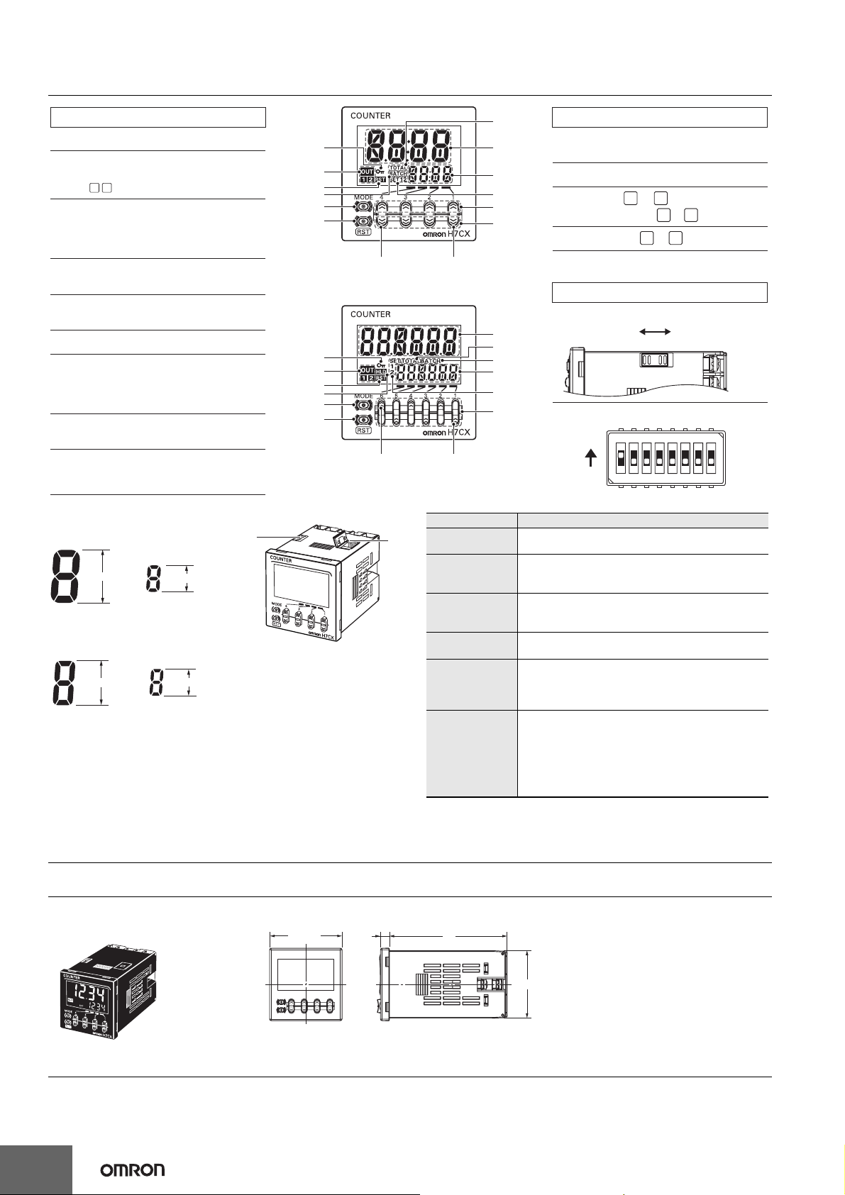
Nomenclature
Display Section
1. Key Protect Indicator (orange)
2. Control Output Indicator (orange)
OUT: (One-stage)
1 2
OUT: (Two-stage)
3. Reset Indicator (orange)
(Lit when the reset input (1) or Reset Key is ON.)
Displayed only when the configuration selection
mode is not tachometer mode.
4. Total Count Indicator
(Lit when the total count value is displayed.)
5. Batch Indicator
(Lit when the batch count value is displayed.)
6. Set Value 1, 2 Stage Indicator
7. Present Value (Main Display)
(Character height: 12 mm (6-digit: 10 mm), red*)
* Characters on models with screw terminals (H7CX-A11@)
can be switched between red, green, and orange.
8. Set value (Sub-display)
(Character height: 6 mm, green)
9. Hold Display (orange)
Displayed only when the configuration selection
mode is not tachometer mode.
Model with 4 Digits
Character Size
for Main Display
12 mm
Character Size
for Sub-display
6 mm
14
Model with 6 Digits
Character Size
for Main Display
10 mm
Character Size
for Sub-display
6 mm
1
2
3
5
10
11
(Front view of 4-digit model)
1
2
3
9
10
11
RST
(Front view of 6-digit model)
1
4
7
8
6
12
13
10. Mode Key
(Changes modes and setting items.)
11. Reset Key (See note.)
12. Up Keys to
(6-digit models: to )
13. Down Keys to
1st digit4th digit
Operation Keys
1
4
1 6
1 4
Switches
14. Key-protect Switch
7
4
5
8
6
12
1st digit6th digit
(Default setting) OFF
(Disable)
15. DIP Switch
ON
OFF
12345678
ON
(Enable)
Note: The reset functions depends on the selected configuration.
Configuration Reset operation
1-stage/2-stage
preset counter
Total and preset
counter
Batch counter
Dual counter
Twin counter
Tachometer
Resets the present value and outputs.
• Resets the present value and outputs.
• When the total count value is displayed, resets the
present value, the total count value, and outputs.
• Resets the present value and OUT2.
• When the batch count value is displayed, resets the
present value, the batch count value, and outputs.
Resets the CP1 present value, CP2 present value, dual
count value, and outputs.
Resets the CP1 present value and output 1 when the
CP1 present value is displayed.
Resets the CP2 present value and output 2 when the
CP2 present value is displayed.
Holds the measurement value and outputs (hold
function).
(When the input mode is 2-input independent
measurement, the CP1 measurement value display will
hold the CP1 measurement value and output 1 and the
CP2 measurement value display will hold the CP2
measurement value and output 2.)
Dimensions (Unit: mm)
Counters
H7CX-A-N/-AS-N/-AW-N/-AWS-N/-AWD1-N/-AWSD1-N/-A4-N/-A4S-N/-A4W-N/-AU-N/-AUD1-N/-AUSD1-N
(Flush Mounting Models)
48 × 48
6
78
44.8 × 44.8
Note: M3.5 terminal screw (effective length: 6 mm)
10
Page 11
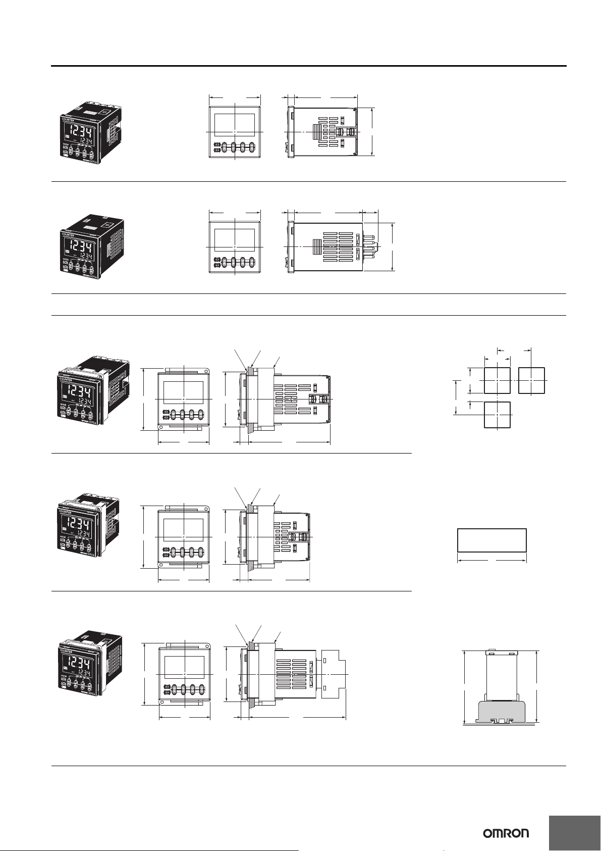
H7CX-A@-N
H7CX-AD-N/-ASD-N/-AWSD-N/-A4D-N/-A4SD-N/-A4WSD-N (Flush Mounting Models)
48 × 48
H7CX-A11-N/-A11S-N/-A11D1-N/-A11SD1-N/-A114-N/-A114S-N/-A114D1-N (Flush Mounting/Surface Mounting Models)
48 × 48
Dimensions with Flush Mounting Adapter
H7CX-A-N/-AS-N/-AW-N/-AWS-N/-AWD1-N/-AWSD1-N/-A4-N/-A4S-N/-A4W-N
(Provided with Adapter and Waterproof Packing)
Y92S-29 (provided)
Waterproof Packing
6
6
Y92F-30 (provided)
Panel
Flush Mounting Adapter
59
44.8 × 44.8
Note: M3.5 terminal screw (effective length: 6 mm)
63.7
14.4
44.8 × 44.8
Panel Cutouts
Panel cutouts are as shown below. (according
to DIN43700).
45
0
+
0.6
60 min.
58
48
(51)
76.57.5
H7CX-AD-N/-ASD-N/-AWSD-N/-A4D-N/-A4SD-N/-A4WSD-N
(Provided with Adapter and Waterproof Packing)
Panel
Y92S-29 (provided)
Waterproof Packing
58
48
(51)
7.5 57.5
Y92F-30 (provided)
Flush Mounting Adapter
H7CX-A11-N/-A11S-N/-A11D1-N/-A11SD1-N/-A114-N/-A114S-N/-A114D1-N
(Adapter and Waterproof Packing Ordered Separately)
Y92S-29 (order separately)
Waterproof Packing
Panel
Y92F-30 (order separately)
Flush Mounting Adapter
+
0.6
45
0
15 min.
60 min.
Note: 1. The mounting panel thickness
should be 1 to 5 mm.
2. To allow easier operation, it is
recommended that Adapters be
mounted so that the gap between
sides with hooks is at least 15 mm
(i.e., with the panel cutouts
separated by at least 60 mm).
3. It is possible to mount counters
side by side, but only in the
direction without the hooks. If they
are mounted side-by-side, waterresistance will be lost.
n Units mounted
side by side
A
A=(48n−2.5)
With Y92A-48F1 attached.
A={48n−2.5+(n−1)×4}
With Y92A-48 attached.
A=(51n−5.5)
+1
−0
+1
−0
+1
−0
Dimensions with Front
Connecting Socket
58
48
(51)
7.5 89.9
H7CX
103.2*
P2CF-11(-E) Front Connecting Socket
* These dimensions depend on the kind of DIN Track.
(Reference value)
-A11@
(order separately)
100.9
11
Page 12
H7CX-A@-N
G
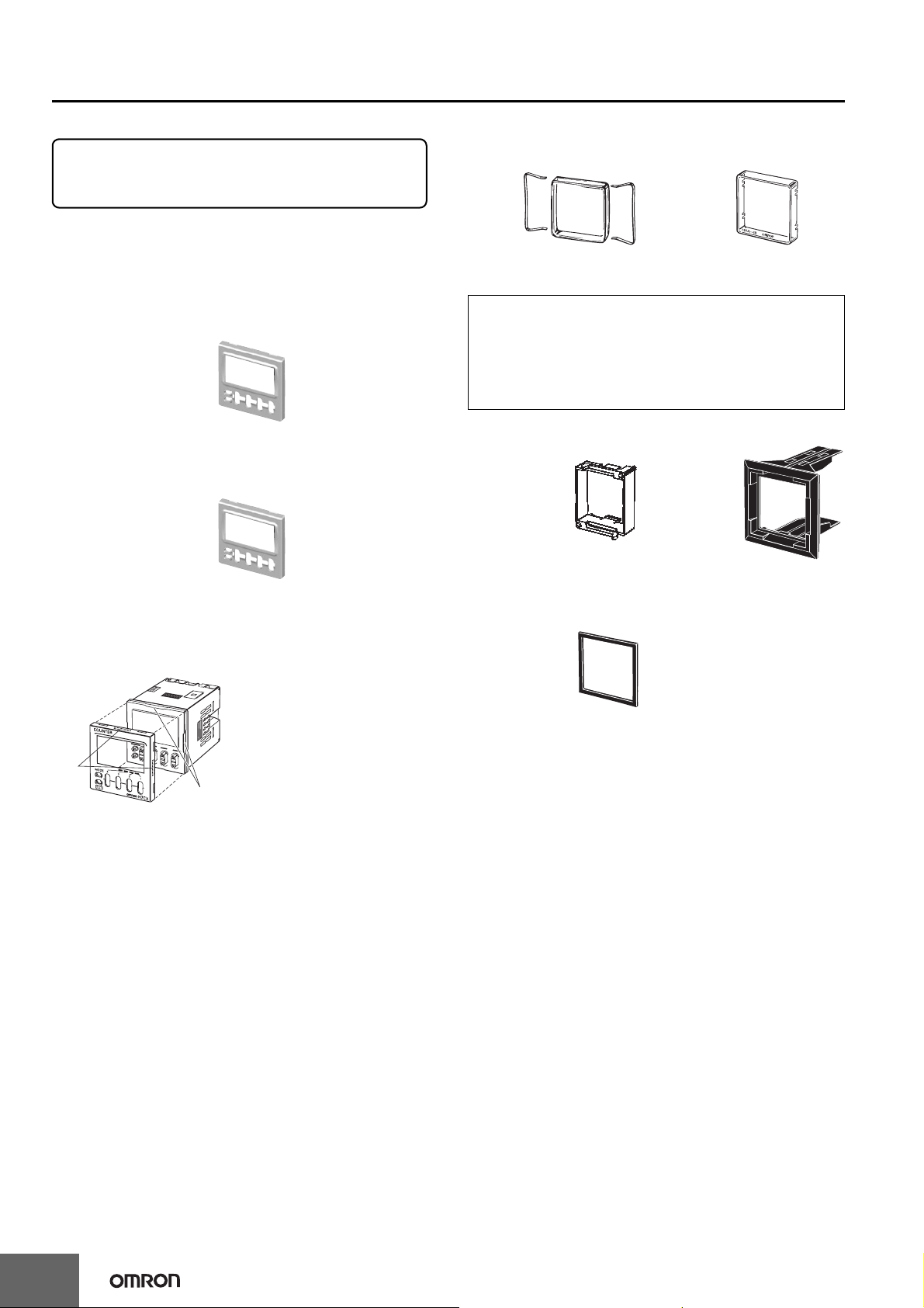
Accessories (Order Separately)
Note: Depending on the operating environment, the condition
of resin products may deteriorate, and may shrink or
become harder. Therefore, it is recommended that resin
products are replaced regularly.
Front Panel (Replacement Part)
You can change the color of the Front Panel when mounting the
Counter/Tachometer. The Counter/Tachometer is shipped with a
black (N1.5) Front Panel. "COUNTER" is printed on the front of
Replacement Front Panels.
Y92P-CXC4
4-digit Counter
Light gray (5Y7/1)
Y92P-CXC4S
4-digit Counter
White (5Y9.2/0.5)
Y92P-CXT4B
4-digit Counter
Black (N1.5)
Y92P-CXT6G
6-digit Counter
Light gray (5Y7/1)
Y92P-CXT6S
6-digit Counter
White (5Y9.2/0.5)
Y92P-CXT6B
6-digit Counter
Black (N1.5)
Replacement Method
The Front Panel is attached to the
Counter/Tachometer with tabs in
four locations. To remove the
Front Panel, open the tabs and
pull the Front Panel forward. To
attach the Front Panel, press it
Ta bs
onto the Counter/Tachometer so
that all four tabs lodge into the
grooves on the body of the
Grooves
Counter/Tachometer.
Soft Cover
Y92A-48F1
Hard Cover
Y92A-48
Protecting the Counter/Tachometer in Environments
Subject to Oil
The H7CX's panel surface is water-resistive (conforming to IP@6,
UL Type 4X) and so even if drops of water penetrate the gaps
between the keys, there will be no adverse effect on internal circuits.
If, however, there is a possibility of oil being present on the
operator's hands, use the Soft Cover. The Soft Cover ensures
protection equivalent to IP54F against oil. Do not, however, use the
H7CX in locations where it would come in direct contact with oil.
Flush Mounting Adapter
Y92F-30
Order the Flush
Mounting Adapter with
the following model
number separately if it
is lost or damaged.
Note: The
Waterproof
Packing is
included with
models with
screw
terminals.
Y92F-45
Use this Adapter to
install the Counter/
Tachometer in a
cutout previously
made for a DIN 72
× 72 mm device
(panel cutout: 68 ×
68 mm).
Waterproof Packing
Y92S-29
Note: The
Waterproof
Packing is
included with
models with
screw
terminals.
The Waterproof Packing will deteriorate, harden, and shrink
depending on the application environment. To ensure maintaining the
IP@6, UL Type 4X waterproof level, periodically replace the
Waterproof Packing. The periodic replacement period will depend on
the application environment. You must confirm the proper
replacement period. Use 1 year or less as a guideline. If the
Waterproof Packing is not replaced periodically, the waterproof level
will not be maintained. It is not necessary to mount the Waterproof
Packing if waterproof construction is not required.
Order the Waterproof Packing
separately if it is lost or damaged. The
Waterproof Packing can be used to
achieve IP66 protection.
12
Page 13
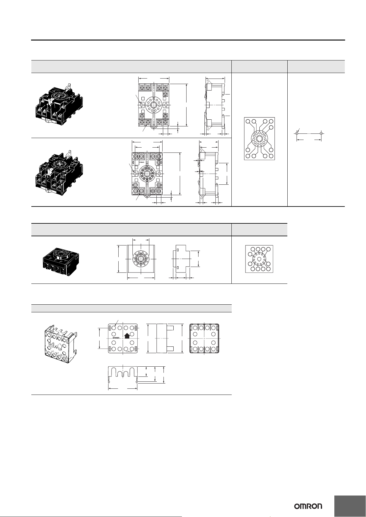
Connection Sockets
4
4
Front Connecting Socket
Model Dimensions
P2CF-11
Two, 4.5-dia. holes
50 max.
70 max.
31.2 max.
Terminal arrangement
and internal connections
H7CX-A@-N
Mounting hole
dimensions
4
4
3
12
7.8
70 max.
4
7.8
3
31.2 max.
30
3
1.2
5
35.
4.5
P2CF-11-E
(Finger-safe Type)
Eleven, M3.5 × 7.5 sems screws
Two, 4.5-dia. holes
Eleven, M3.5 × 7.5 set screws
7865
P2CF-11-E
9
10A250VAC
RESISTIVE
10 11
50 max.
±0.2
40
Note: Round crimp terminals cannot be used on Finger-safe Sockets. Use forked crimp terminals.
Back-connecting Sockets
Model Dimensions
P3GA-11
45
27 dia.
45
25.6
4.5
16.3
6.2
Note: A Y92A-48G Terminal Cover can be used with the Socket to create a finger-safe construction.
Terminal arrangement
and internal connections
8 7 6 5
9 3
10 11 1 2
(Top View)
876
5
4
3
9
101112
(Bottom View)
4
Two, M4 or 4.5-dia. holes
±0.2
40
Note: The Socket can
also be mounted
to DIN track.
Terminal Covers for P3GA-11 Back-connecting Socket
Model Dimensions
Y92A-48G
34
Note: The Terminal Cover can be used with a Back-mounting Socket (P3GA-11) to create a finger-safe construction.
Twelve, 6.4-dia. holes
Y92A-48G
UP
P C
47.4
47.7 × 47.7
16.5
24.6
48 × 48
27.6
13
Page 14
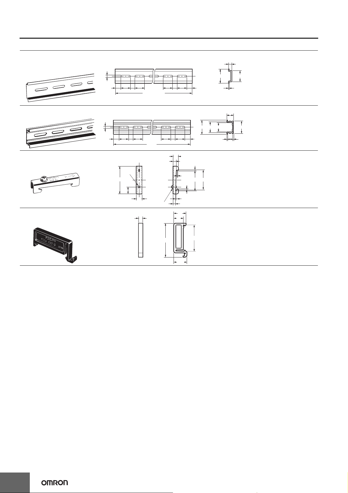
H7CX-A@-N
Optional Products for Track Mounting
Mounting Track
PFP-100N
PFP-50N
Mounting Track
PFP-100N2
End Plate
PFP-M
Spacer
PFP-S
4.5
4.5
15 25 2510
10
15 25 25
M4 × 8
pan head
screw
50
11.5
1,000 (500)*
1,000
10
M4 spring washer
5
25 25 1510
1025 25
10
16
12
7.3
15 (5)*
* The values shown in parentheses
are for the PFP-50N.
±
0.3
6.2
1.8
1
35.5 35.3
1.8
1.3
4.8
±0.15
±0.3
35
242735
1
±0.15
27
1
16
29.2
1.5
Note: Order Spacers in increments of 10.
44.3
34.8
16.5
14
Page 15
H7CX-A@-N
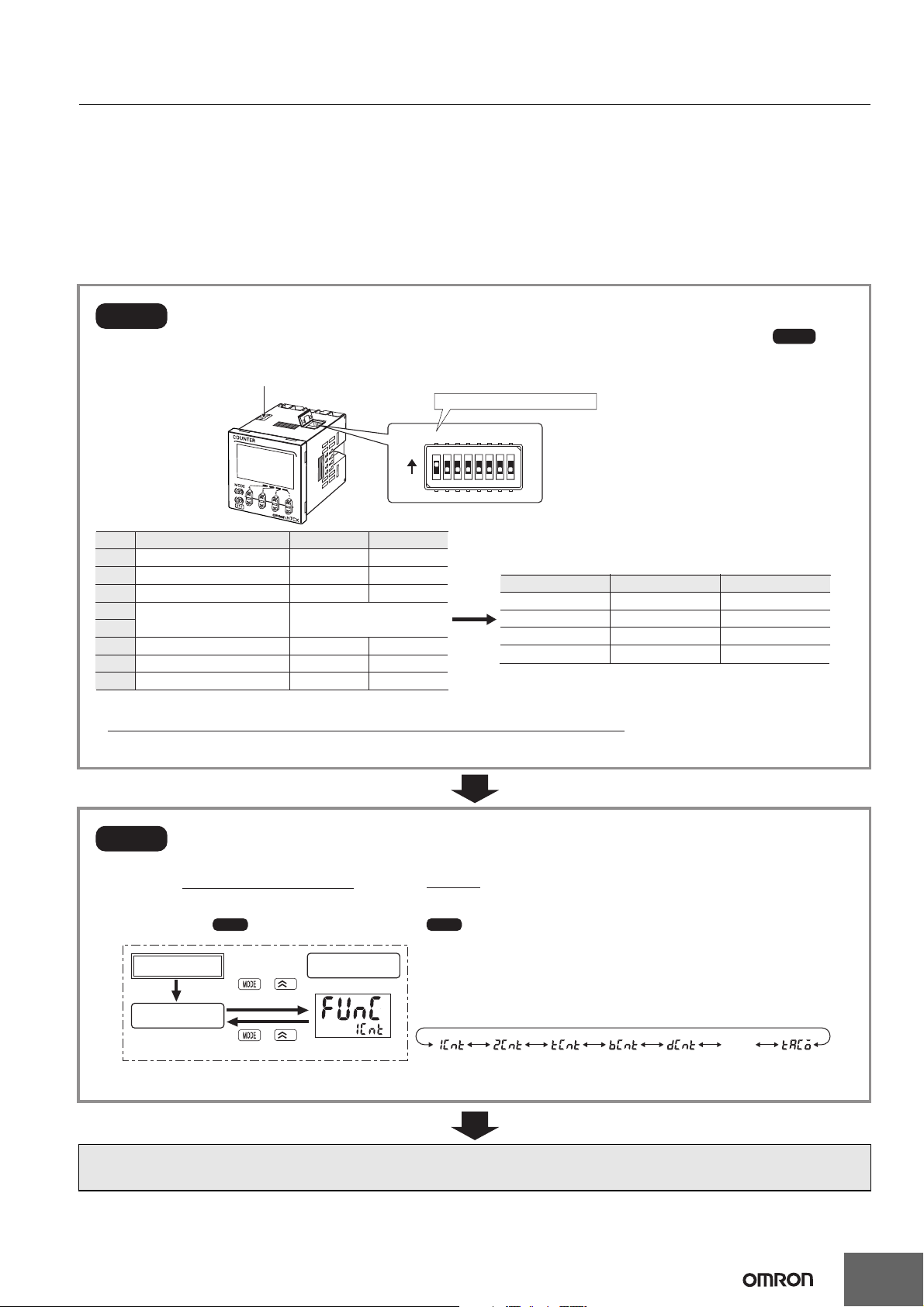
Operating Procedures
Setting Procedure Guide
Setting for Counter Operation
Use the following settings.
Setting for Tachometer Operation
Refer to page page 27.
* At the time of delivery, the H7CX is set to the 1-stage preset counter configuration. (2-stage models are set to the 2-stage preset counter configuration.) Refer to page page 35 for information
on switching models.
I/O Functions for Counter Operation
*
*
Counter
Step1
Set the basic parameters.
(If the desired I/O mode is not listed below or to set all parameters using the front panel keys, perform ,
Step3
below.)
Key-protect switch
Be sure to set pin 1 to ON.
ON
OFF
12345678
Item OFF ON
1
DIP switch settings
2
Counting speed
3
Input mode
4
Output mode
5
6
Output time 0.5 s 0.05 s
7
Minimum reset signal
8
Input selection
Note: All pins are factory-set to OFF.
Disabled Enabled
30 Hz 5 kHz
UP DOWN
Refer to the table on the right.
20 ms 1 ms
NPN PNP
OFF
ON
OFF
ON
OFF
OFF
ON
ON
Output modePin 5Pin 4
N
F
C
K-1
• When setting functions using the DIP switch, be sure to set pin 1 of the DIP switch to ON.
• DIP switch settings are effective when the power is turned ON again. (Perform DIP switch settings while the power is OFF.)
Step2
The H7CX-A@-N is a Counter that contains more than one functional counter.
When using the Counter in any mode other than the default mode*, use the following chart to enter
Configuration Selection Mode and set the functions that are suitable to the application.
* The default mode is 1-stage preset counter configuration (2-stage preset counter configuration for 2-stage models).
Step2 Step1
Note: can be performed first, followed by .
Power ON
Run mode
+
Hold down for 1 s min.
+
Hold down for 1 s min.
Configuration
selection mode
1
1
Select the function from Table 1 using the U (D) Key.
(1-stage
preset
counter)
Note:
(2-stage
preset
counter)
The configuration that can be selected depends on the model.
(Total and
preset counter)
(Batch
counter)
(Dual
counter)
After making DIP switch settings for basic operations, advanced functions can be added using the operation keys.
For details, refer to page page 16.
twn
(Twin
counter)
(Tachometer)
15
Page 16
H7CX-A@-N
Counter
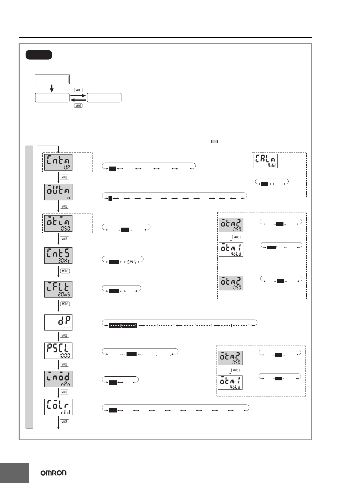
Step3
Parameters that cannot be set with the DIP switch are set with the operation keys on the front panel.
Change to Function Setting Mode.
Power ON
*1
3 s min.
Run mode
setting mode
3 s min.
Function
*2
*1 If the mode is switched to the function setting mode during operation, operation will continue.
*2 Changes made to settings in function setting mode are enabled for the first time when the mode is changed to run mode. Also,
when settings are changed, the counter is reset (present value initialized and output turned OFF) on returning to run mode.
The characters displayed in reverse video are the default settings.
When performing settings with operation keys only, set pin1 of the DIP switch to OFF (factory setting).
If pin 1 of the DIP switch is set to ON, the setting items indicated by will not be displayed.
For 6-digit models, only U Keys are provided.
*3
Displays for 6-digit models are given in parentheses.
Input mode
(CNTM)
• Set the input mode using the U (D) Keys.
up
Note: Displayed only when Twin Counter Mode is not selected.
*5 Displayed for output modes other than K-2, D, L, and H only.
Output mode
(OUTM)
Output
time
(OTIM)
Counting
speed
(CNTS)
Reset input
signal width
(IFLT)
• Set the output mode using the U (D) Keys.
n
(N)
*6 Displayed only when the input mode is ud-a, ud-b, or ud-c.
*7
(Not displayed when the function is set to twn.)
• Set each digit using the individual U (D) Keys.
0.01 99.990.50
Note: Displayed only when the output mode is C, R, K-1, P, Q, A,
or K-2.
• Set the counting speed using the U (D) Keys.
30hz
(30 Hz) (5 kHz)
• Set the Reset input signal width using the U (D) Keys.
20ms
Function Setting Mode
For details on operations and display in run mode, refer to page page 20.
The display depends on the selected configuration.
*5
*5
down
(DOWN) (
f
(F) (C) (R) (K-1) (P) (Q) (A) (K-2) (D) (L) (H)
ud-a ud-b ud-c
UP/DOWN A)(UP/DOWN B)(UP/DOWN C
crk-1 k-2pqa dlh
)(UP)
*6 *6 *6 *6
*7 Set each digit using the individual U (D) Keys.
When using as a 2-stage preset counter
(0.50 s) (99.99 s)(0.01 s)
When using as a batch counter
1ms
(1 ms)(20 ms)
*3 When Using Dual Counter
Operation
Dual count
calculating
mode
• Set the dual count calculating
mode using the UD Keys.
(Addition) (Subtraction)
*4 Displayed only when the output mode is K-2,
D, L, or H.
One-shot
output 2
time
(OTM2)
Note: Displayed only when the
One-shot
output 1
time
(OTM1)
If the output time is 0.00, hold is displayed.
Note: Displayed for output modes
HOLD cannot be set when
One-shot
output 2
time
(OTM2)
Note: Displayed only when the
(ADD)
*4
subadd
0.50
0.01 99.99
(0.50 s) (99.99 s)(0.01 s)
output mode is C, R, K-1, P, Q,
A, or K-2.
hold 0.01 99.99
(0.01 s) (99.99 s)
(Outputs held)
other than D, L, and H.
the output mode is K-2.
0.01 0.50 99.99
(0.50 s) (99.99 s)(0.01 s)
output mode is C, R, K-1, P, Q,
A, or K-2.
16
Decimal
point position
(DP)
Prescale
value
(PSCL)
NPN/PNP
input mode
(IMOD)
Display color
(COLR)
• Set the decimal point position using the U (D) Keys.
(No decimal point)
(One digit after
decimal point)
(Two digits after
decimal point)
• Set each digit using the individual U (D) Keys.
0.001
1.000
(9.999)
99.9999.999
(99.999)(1.000)(0.001)
• Set the NPN/PNP input mode using the U (D) Keys.
pnpnpn
(PNP input)(NPN input)
• Set the display color using the U (D) Keys.
grnred org r-g g-r r-o o-r g-o o-g
(Red) (Green) (Orange)
(Red-green) (Green-red) (Red-orange) (Orange-red)
(Three digits after
decimal point)
*7 Set each digit using the individual U (D) Keys.
Twin Counter
(Green-orange) (Orange-green)
Output 2
output
time
(OTM2)
Note: Displayed only when the
Output 1
output
time
(OTM1)
Note: Displayed only when the
0.500.01 99.99
(0.50 s) (99.99 s)(0.01 s)
output mode is C, R, K-1, P,
Q, or A.
0.500.01 99.99
(0.50 s) (99.99 s)(0.01 s)
output mode is C, R, K-1, P,
Q, or A.
Note: Displayed for terminal-block models (except H7CX-A11@) only.
To next pageFrom next page
Page 17
H7CX-A@-N
Counter
page
From previous
page
To previous
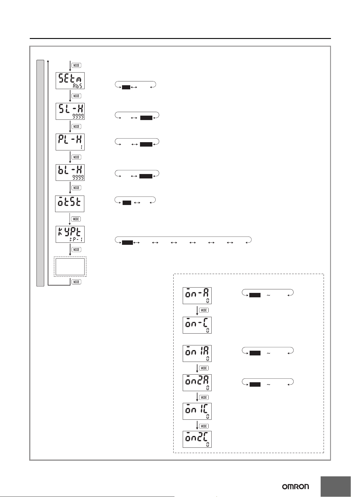
Function Setting Mode
Absolute value
setting/forecast
value setting
(SETM)
Set value
upper limit
(SL-H)
Forecast
setting
upper limit
(PL-H)
Batch count
upper limit
(BL-H)
Output
allocation
change
Key protect
level
(KYPT)
*8
Output ON
count alarm set
value/monitor
value
• Make the absolute value setting and forecast setting using the U (D) Keys.
ofstabs
Note: Displayed only when the configuration selection mode is set to the 2-stage function 2cnt.
(OFST)(ABS)
• Set each digit using the individual U (D) Keys.
99991
Note: 1 to 999999 for 6-digit models
(9999)(1)
• Set each digit using the individual U (D) Keys.
99991
Note: 1 to 999999 for 6-digit models.
Note: Displayed only when the configuration selection mode is set to the 2-stage function 2cnt and a forecast value is set.
(9999)(1)
• Set each digit using the individual U (D) Keys.
99991
Note: 1 to 999999 for 6-digit models.
Note: Displayed only when the output mode is set to bcnt.
Note: Displayed only for "-AU@" models.
off: Output 1 = 12, 13, Output 2 = 3, 4, 5 on: Output 1 = 3, 4, 5, Output 2 = 12, 13
The numbers are the terminals numbers.
(9999)(1)
onoff
(ON)(OFF)
• Set the key protect level using the U (D) Keys.
kp-1 kp-2 kp-3 kp-4 kp-5
(KP-1) (KP-2) (KP-3) (KP-4) (KP-5) (KP-6) (KP-7)
*8 Set each digit using the individual U (D) Keys.
kp-6 kp-7
Procedure for Models Other than “-@W@” Models
Output
ON count
alarm set
value
Output
ON count
monitor
value
Note: The monitor value is only displayed. It cannot be set.
Procedure for “-@W@” Models
Output 1
(OUT1) ON
count alarm
set value
Output 2
(OUT2) ON
count alarm
set value
Output 1
(OUT1) ON
count monitor
value
Output 2
(OUT2) ON
count monitor
value
99990
(9999 × 1000 times)(0 × 1000 times)
99990
(9999 × 1000 times)(0 × 1000 times)
99990
(9999 × 1000 times)(0 × 1000 times)
Note: The monitor value is only displayed. It cannot be set.
Note: The monitor value is only displayed. It cannot be set.
17
Page 18

H7CX-A@-N
Counter
Explanation of Functions
Items marked with stars ★ can be set using the DIP switch.
Input Mode (cntm)★
Set increment mode (UP), decrement mode (DOWN), or one of the
increment/decrement modes (UP/DOWN A, UP/DOWN B, or UP/
DOWN C) as the input mode.
Input modes other than UP or DOWN modes cannot be set using the
DIP switch and so use the operation keys if other modes are required.
(For details on the operation of the input modes, refer to Input Modes
and Present Value on page page 21.)
Dual Count Calculating Mode ( calm)
When using as a dual counter, select either ADD (addition) or SUB
(subtraction) as the calculation method for the dual count value.
ADD: Dual count value = CP1 PV + CP2 PV
SUB: Dual count value = CP1 PV − CP2 PV
Output Mode (outm)★
Set the way that control output for the present value is output. The
possible settings are N, F, C, R, K-1, P, Q, A, K-2, D, L, and H.
Output modes other than N, F, C, or K-1 cannot be set using the DIP
switch and so use the operation keys if other modes are required. The
output modes that can be set vary with the model.
(For details on the operation of the output modes, refer to Input/
Output Mode Settings on page page 22.)
One-shot Output Time (otim)★
Set the one-shot output time (0.01 to 99.99 s) for control output.
One-shot output can be used only when C, R, K-1, P, Q, A, or K-2 is
selected as the output mode. Output times other than 0.5 s or 0.05 s
cannot be set with the DIP switch and so use the operation keys if
other settings are required.
One-shot Output 2 Time (otm2)★
Set the one-shot output time (0.01 to 99.99 s) for control output
(OUT2).
One-shot output can be used only when C, R, K-1, P, Q, A, or K-2 is
selected as the output mode. Output times other than 0.5 s or 0.05 s
cannot be set with the DIP switch and so use the operation keys if
other settings are required.
One-shot Output 1 Time (otm1)
Set the one-shot output time (0.01 to 99.99 s) for control output
(OUT1).
One-shot output can be used only when D, L, or H is selected as the
output mode.
If the output time is set to 0.00, hold is displayed, and outputs are
held.
Counting Speed (cnts)★
Set the maximum counting speed (30 Hz/5 kHz) for CP1 and CP2
inputs together.
If contacts are used for input signals, set the counting speed to 30 Hz.
Processing to eliminate chattering is performed for this setting.
Reset Input Signal Width (iflt)★
Set the reset input signal width (20 ms/1 ms) for reset/reset 1 and total
reset/reset 2 inputs together.
If contacts are used for the input signal, set the input signal width to
20 ms. Processing to eliminate chattering is performed for this setting.
Decimal Point Position (dp)
Decide the decimal point position for the present value, CP1/CP2
present values, set value (SV1, SV2), total count value, and dual
count set value.
Prescale Value (pscl)
Pulses input to the counter are converted according to the specified
prescale value.
(Setting range: 0.001 to 99.999 for 6-digit models and 0.001 to 9.999
for 4-digit models.)
Example: To display the feed distance for systems that output 25
pulses for a feed length of 0.5 m in the form @@.@@ m:
1. Set the decimal point position to 2 decimal places.
2. Set the prescale value to 0.02 (0.5 ÷ 25).
0.5 m
25 pulses
Encoder
• Observe the following points when setting a prescale value.
Set the set value to a value less than {Maximum countable value
− Prescale value}.
Example: If the prescale value is 1.25 and the counting range is
0.000 to 999.999, set the set value to a value less than 998.749
(= 999.999 − 1.25).
If the set value is set to a value greater than this, output will not turn
ON.
• Output will turn ON, however, if a present value overflow occurs
(FFFFFF or FFFF).
Note: If the prescale value setting is incorrect, a counting error will
occur. Check that the settings are correct before using this
function.
NPN/PNP Input Mode (imod)
Select either NPN input (no-voltage input) or PNP input (voltage
input) as the input format. When using a two-wire sensor, select NPN
input.
The same setting is used for all external inputs.
For details on input connections, refer to Input Connections on page
page 9.
Display Color (colr) (Displayed for terminal block models
(except H7CX-A11@) only.)
Set the color used for the present value.
Output OFF* Output ON*
red
grn
org
r-g
g-r
r-o
o-r
g-o
o-g
* Output 2 for 2-stage models.
With the twin counter, output 1 and output 2 will both turn OFF when
the output status is OFF. Either output 1 or output 2 will turn ON when
the output status is ON.
Red Green
Green Red
Red Orange
Orange Red
Green Orange
Orange Green
Red (fixed)
Green (fixed)
Orange (fixed)
18
Page 19

H7CX-A@-N
Counter
Absolute Value Setting/Forecast Value Setting (setm)
For the 2 count output mode, an absolute value setting (abs) or
forecast value setting (ofst) can be set for set value 1.
When a forecast value is set, specify the forecast value set value (i.e.,
the deviation for the set value).
The forecast output (output 1) turns ON when the present value
reaches the forecast value.
If the forecast set value is greater than or equal to the set value, the
forecast output (output 1) will turn ON as soon as counting starts.
Example: F Mode
Set value 2
Set value 1
0
Control output 1 (OUT1)
Control output 2 (OUT2)
If the forecast value setting is used, specify the set value 2 minus the
forecast value setting for set value 1.
Example: F Mode
Forecast set value
Forecast output (OUT1)
Set value
Forecast
value
0
Count value
Count value
Output ON Count Alarm Set Value (on-a)
Set the alarm value for the output ON count.
The limit can be set to between 0
× 1000 (0 times) and 9999 × 1000
(9,999,000 times). Only the underlined values are set. The alarm will
be disabled if 0 is set.
If the total ON count of the output exceeds the alarm set value, e3
will be displayed on the Timer to indicate that the output ON count
alarm value was exceeded. Refer to Self-diagnostic Function on page
page 36 for information on the e3 display.
ON Count Alarm Set Values for Outputs 1 and 2 (OUT1
and OUT2) (on1a and on2a)
Set the ON count alarm values for the outputs 1 and 2.
The limit can be set to between 0
× 1000 (0 times) and 9999 × 1000
(9,999,000 times). Only the underlined values are set. The alarm will
be disabled if 0 is set.
If the total ON count of instantaneous output 1 or 2 exceeds the alarm
set value, e3 will be displayed on the Timer to indicate that the output
ON count alarm value was exceeded. Refer to Self-diagnostic
Function on page page 36 for information on the e3 display.
Output ON Count Monitor Value (on-c)
The monitor value is only displayed. It cannot be set.
The output ON count will be 1,000 times the displayed value.
ON Count Monitor Values for Outputs 1 and 2 (OUT1 and
OUT2) (on1c and on2c)
The monitor value for output 1 or 2 is only displayed. It cannot be set.
The output ON count will be 1,000 times the displayed value.
Control output (OUT 2)
Set Value Upper Limit (sl-h)
Set the upper limit for the set value when it is set in run mode.
The setting can be made from 1 to 9999 for 4-digit models and from
1 to 999999 for 6-digit models.
Forecast Set Upper Limit (pl-h)
Set the upper limit for the forecast set value.
The setting can be made from 1 to 9999 for 4-digit models and from
1 to 999999 for 6-digit models.
Batch Count Upper Limit (bl-h)
Set the upper limit for the batch count value. The setting can be made
from 1 to 9999 for 4-digit models and from 1 to 999999 for 6-digit
models.
Output Allocation (otst)
When using an H7CX-AU@-N model as a 2-stage counter, the output
can be flexibly allocated to either stage 1 or 2.
The transistor output can be allocated to SV1 and the contact output
to SV2 or vice verse, as in the following tables.
H7CX-AU-N/-AUD1-N
Output 1 Output 2
off Transistor (12-13) Contact (3, 4, 5)
on Contact (3, 4, 5) Transistor (12-13)
H7CX-AUSD1-N
Output 1 Output 2
off Transistor (12-13) Transistor with diode (3, 4, 5)
on Transistor with diode (3, 4, 5) Transistor (12-13)
Key Protect Level (kypt)
Set the key protect level.
Refer to Key Protect Level on page page 36.
19
Page 20

H7CX-A@-N
Counter
Operation in Run Mode
I/O Functions for Counter Operation
• Set values for each digit as required using the U (D) Keys. (U Key only for 6-digit models.)
1-stage Preset Counter
Present value
Set value
2-stage Preset Counter with
Absolute Value Setting
Present value
Set value 1
Present value
Set value 2
• Present Value
Shows the present count value.
• Set Values (Set Value 1 and Set Value 2)
Set the set values.
When the present value reaches the set value (set
value 1 or set value 2), a signal is output according
to the specified output mode.
2-stage Preset Counter with
Forecast Value Setting
Present value
Set value
Present value
Forecast Set Value
• Present Value
Shows the present count value.
• Set Values
Set the set values.
• Forecast Set Value
Set the deviation for the set value.
Total and Preset Counter
Present value
Set value
Total count value
• Present Value/Set Value
Same as 1-stage preset counter.
• Total Count Value
Shows the present total count value.
Batch Counter
Present value
Set value
Batch count value
Batch count set value
• Present Value/Set Value
Same as 1-stage preset counter.
• Batch Count Value
Shows the number of times the count has been
completed for the present value.
• Batch Count Set Value
Set the batch count set value.
When the batch count value reaches the batch
count set value, batch output (OUT1) turns ON.
Dual Counter
Dual count value
Dual count
set value
CP1 present value
CP2 present value
• Dual Count Value
Shows the sum of the CP1 present value and
CP2 present value when the dual count
calculating mode is ADD and shows the value
obtained by subtracting the CP2 present
value from the CP1 present value when the
dual count calculating mode is SUB.
• Dual Count Set Value
Set the dual count set value.
When the dual count value reaches the dual
count set value, signals are output according
to the specified output mode.
• CP1/CP2 Present Value
Show the present count values for CP1 and
CP2 present values respectively.
Twin Counter
Present value 1
Set value 1
Present value 2
Set value 2
• Present Values 1 and 2
Shows the present count value 1 or 2.
• Set Values 1 and 2
Setting for present value 1 or 2.
20
Page 21

Input Modes and Present Value (See note 1.)
I/O Functions for Counter Operation
UP (Increment) Mode DOWN (Decrement) Mode
CP1: Count input; CP2: Prohibit (gate) input
H
CP1
L
H
CP2
L
Present value
2
1
0
A
must be greater than the minimum signal width. (See note 2.)
0
CP1: Prohibit (gate) input; CP2: Count input
H
*CP1
L
H
CP2
L
Present value
1
0
A
must be greater than the minimum signal width. (See note 2.)
* Counting starts when the CP1 is turned ON after turning ON the power.
0
A A
Prohibit
3
A A
Prohibit
2
5
4
5
4
3
H7CX-A@-N
CP1: Count input; CP2: Prohibit (gate) input
H
CP1
L
H
CP2
L
n
n−1
Present value
A
must be greater than the minimum signal width. (See note 2.)
0
n−2
CP1: Prohibit (gate) input; CP2: Count input
H
*CP1
L
H
CP2
L
n
n−1
Present value
A
must be greater than the minimum signal width. (See note 2.)
0
A A
Prohibit
n−3
A A
Prohibit
n−2
Counter
n−4
n−5
n−3
n−4
n−5
UP/DOWN A Command Input Mode UP/DOWN B Individual Input Mode
H
CP1
L
H
CP2
L
Present value
0
0
A
must be greater than the minimum signal width. (See note 2.)
2
1
A A
3
2
1
UP/DOWN C Quadrature Input Mode
H
CP1
L
B B B B
H
CP2
L
Present value
1
0
0
B
must be at least 1/2 the minimum signal width. (See note 2.)
3
2
2
1
H
CP1
L
H
CP2
L
3
2
Present value
1
0
0
3
2
2
11
3
2
Note: 1. If the configuration selection is set to dual counter, CP1 and
CP2 input will operate in the same way as the count input
(CP1) of UP (increment) mode.
A
2. must be greater than the minimum signal width and
B
must be at least 1/2 the minimum signal width.
If they are less, a count error of ±1 may occur.
3
2
3. The meaning of the H and L symbols in the tables is explained
below.
Symbol
Input method
H Short-circuit 4.5 to 30 VDC
L Open 0 to 2 VDC
Minimum signal width: 16.7 ms (when maximum counting speed = 30 Hz)
100 µs (when maximum counting speed = 5 kHz)
No-voltage input
(NPN input)
Voltage input (PNP
input)
21
Page 22

H7CX-A@-N
Counter
Input/Output Mode Settings
I/O Functions for Counter Operation
If a 1-stage model or 2-stage model is incorrectly used as twin counter, the operation for
output 2 will be performed. When using a 2-stage model as a 1-stage preset counter,
total and preset counter, or dual counter, OUT1 and OUT2 turn ON and OFF
simultaneously.
One-shot output from OUT1
Self-holding
output
Self-holding
output
One-shot
output from OUT2
(The one-shot output time can be
set in the range 0.01 to 99.99s.)
Output
mode
setting
N
F
C
R
Reset/
reset 1
999999
Set value 2
Set value 1
OUT1
OUT2
Reset/
reset 1
999999
Set value 2
Set value 1
OUT1
OUT2
Reset/
reset 1
999999
Set value 2
Set value 1
OUT1
OUT2
Reset/
reset 1
999999
Set value 2
Set value 1
OUT1
OUT2
Input mode
UP DOWN UP/DOWN A, B, C
Operation after count
completion
The outputs and present
value display are held
0
until reset/reset 1 is
input.
The present value
display continues to
0
increase/decrease.
The outputs are held until
reset/reset 1 is input.
As soon as the count
reaches SV, the present
value display returns to
the reset start status.
The present value display
does not show the
present value upon count-
0
up.
The outputs repeat oneshot operation.
OUT1 self-holding output
turns OFF after the OUT2
one-shot output time.
The OUT1 one-shot
output time is
independent of OUT2.
The present value
display returns to the
reset start status after
the one-shot output time.
The outputs repeat oneshot operation.
0
OUT1 self-holding output
turns OFF after the
OUT2 one-shot output
time.
The OUT1 one-shot
output time is
independent of OUT2.
22
K-1
Reset/
reset 1
999999
Set value 2
Set value 1
OUT1
OUT2
The present value
display continues to
increase/decrease.
OUT1 self-holding output
turns OFF after the
0
OUT2 one-shot output
time.
The OUT1 one-shot
output time is
independent of OUT2.
Page 23

H7CX-A@-N
a
9
Counter
Output
mode
setting
P
Q
Reset/
reset 1
999999
Set value 2
Set value 1
OUT1
OUT2
Reset/
reset 1
999999
Set value 2
Set value 1
OUT1
OUT2
Input mode
UP DOWN UP/DOWN A, B, C
0
0
One-shot output from OUT1
Self-holding
output
Self-holding
output
One-shot
output from OUT2
The present value
display does not
change during the
one-shot output time
period, but the actual
count returns to the
reset start status.
The output will return
to one-shot mode.
The outputs repeat
one-shot operation.
OUT1 self-holding
output turns OFF after
the OUT2 one-shot
output time.
The OUT1 one-shot
output time is
independent of OUT2.
The present value
continues to increase/
decrease for the oneshot output time, but
returns to the reset
start status after the
one-shot output time
has elapsed.
The outputs repeat
one-shot operation.
OUT1 self-holding
output turns OFF after
the OUT2 one-shot
output time.
The OUT1 one-shot
output time is
independent of OUT2.
(The one-shot output time c
set in the range 0.01 to 99.
Operation after
count completion
Reset/
reset 1
999999
Set value 2
Set value 1
A
0
OUT1
OUT2
Note: 1. The full scale (FS) for H7CX 4-digit models is 9999.
2. When the present value reaches 999999, it returns to 0.
3. Counting cannot be performed during reset/reset 1 input.
4. If reset/reset 1 is input while one-shot output is ON, one-shot output turns OFF.
5. If there is power failure while output is ON, output will turn ON again when the power supply has recovered.
For one-shot output, output will turn ON again for the duration of the output time setting once the power supply has recovered.
6. Do not use the counter function in applications where the count may be completed (again) while one-shot output is ON.
7. The setting range is 0 to 999,999 (0 to 9,999 for 4-digit models).
The present value
display and OUT1
self-holding output is
held until reset/reset 1
is input.
OUT1 and OUT2 are
independent.
23
Page 24

H7CX-A@-N
Counter
Self-holding
output
Instantaneous
(equals) output
(The one-shot output time can be
set in the range 0.01 to 99.99s.)
One-shot
output
Output
mode
setting
K-2
D
L
Reset/
reset 1
999999
Set value 2
Set value 1
−99999
OUT1
OUT2
Reset/
reset 1
999999
Set value 2
Set value 1
−99999
OUT1
OUT2
Reset/
reset 1
999999
Set value 2
Set value 1
−99999
OUT1
Input mode
Operation after count completion
UP/DOWN A, B, C
The display continues to increase/
0
decrease until the overflow or
underflow value is reached.
One-shot output only.
The display continues to increase/
0
decrease until the overflow or
underflow value is reached.
The outputs are ON while the count is
equal.
The display continues to increase/
decrease until the overflow or
underflow value is reached.
0
OUT1 is held while the present value
is less than or equal to set value 1.
OUT2 is held while the present value
is greater than or equal to set value 2.
OUT2
Reset/
reset 1
999999
Set value 2
Set value 1
H
0
−99999
OUT1
OUT2
Note: 1. Counting cannot be performed during reset/reset 1 input.
2. If reset/reset 1 is input while one-shot output is ON, one-shot output turns OFF.
3. If there is power failure while output is ON, output will turn ON again when the power supply has recovered.
For one-shot output, output will turn ON again for the duration of the output time setting once the power supply has recovered.
4. Do not use the counter function in applications where the count may be completed (again) while one-shot output is ON.
5. The set value is from −99999 to 999999.
24
The display continues to increase/
decrease until the overflow or
underflow value is reached.
OUT1 is held while the present value
is greater than or equal to set value 1.
OUT2 is held while the present value
is greater than or equal to set value 2.
* H mode is available only when using a 6-
digit model as a 2-stage counter.
Page 25

H7CX-A@-N
Counter
Total and Preset Counter Operation
The H7CX has a total counter, separate from the 1-stage preset counter, for counting the total accumulated value.
Reset/reset 1
Total Reset or Reset 2
Present value
0
999999
Total count value
0
Note: The full scale (FS) for H7CX 4-digit models is 9999.
Batch Counter Operation
The H7CX has a batch counter, separate from the 1-stage preset counter, for counting the number of times the count has been completed.
Reset 1
Reset 2 (batch
counter reset)
Set value
Present value
0
Batch count set value
Note: 1. The batch count value is held at 0 during batch counter reset input.
2. If the batch count set value is 0, batch count will be performed but there will be no batch output.
3. The batch count value returns to 0 when it reaches 999,999 (9,999 for 4-digit models).
4. Once batch input has been turned ON, it will return to the ON state after power interruptions.
5. If the batch count set value is changed from a value that is greater than the batch count value to one that is less, batch output will turn ON.
6. After batch output turns ON, the ON state will be held even if the batch count set value is changed to a value greater than the batch count value.
OUT2
Sub-display
Batch count value
(Main display)
OUT1
(batch output)
2
0
Note: The above is for when the output mode is C.
1
• The total counter continues to count the total
accumulated value when the present value is
reset using reset/reset 1 input (Reset Key).
• The total count value is reset when the total
reset/reset 2 input is turned ON.
If the Reset Key is pressed while the total count
value is displayed, the total count value is reset.
The present value is also reset at this time.
• The counting range of the total counter is
−99,999 to 999,999 (−999 to 9,999). The total
count value returns to 0 when it reaches the full
scale limit.
• The batch counter continues after count
completion.
• Batch output is held until batch counter reset is
input.
• When the batch counter reset input is turned
ON, the batch count value is reset, and batch
output turns OFF.
• If the Reset Key is pressed while the batch
count value is displayed, the batch count value
is reset and batch output turns OFF. The
present value is also reset at this time.
• The count value can be incremented and
decremented.
The batch count is only incremented.
• The maximum counting speed for batch counter
operation is 5 kHz. The batch counter counts
the number of times the count reaches the set
value.
Dual Counter Operation
Using the dual counter allows the count from 2 inputs to be added or subtracted and the result displayed. It is possible to specify a set value for
which output turns ON when the set value matches the added or subtracted result.
(1) Dual Count Calculating Mode = ADD
Dual count value = CP1 PV + CP2 PV
Reset 1 (CP1 reset)
Reset 2 (CP2 reset)
Dual count set value
Dual count value
0
CP1 present value
0
CP2 present value
0
OUT1, OUT2
Note: The above is for when the output mode is N.
Note: 1. Counting is not possible for CP1 during reset 1 input. CP2 will not be affected. The dual count value will be calculated based on a CP1 present value of 0.
2. Counting is not possible for CP2 during reset 2 input. CP1 will not be affected. The dual count value will be calculated based on a CP2 present value of 0.
3. The counting range for the dual count value is −99,999 to 999,999 (0 to 9,999 for 4-digit models).
The counting ranges for the CP1 present value and CP2 present value are 0 to 999,999 (0 to 9,999 for 4-digit models).
If a present value exceeds 999,999 (9,999 for 4-digit models), FFFFFF (FFFF for 4-digit models) will be displayed to indicate an overflow, and all counting
will stop.
(2) Dual Count Calculating Mode = SUB
Dual count value = CP1 PV − CP2 PV
Reset 1 (CP1 reset)
Reset 2 (CP2 reset)
Dual count set value
Dual count value
CP1 present value
CP2 present value
0
0
0
OUT1, OUT2
Note: The above is for when the output mode is K-2.
SUB mode can be used only when K-2, D, L,
or H is selected as the output mode with
6-digit models.
• The operation after count completion for the
dual counter value is determined by the output
mode.
• The CP1 present value is reset when reset 1
input is turned ON.
The CP2 present value is reset when reset 2
input is turned ON.
• If the Reset Key is pressed while the dual count
value, CP1 present value, or CP2 present value
is displayed, all of the present values are reset
and outputs turn OFF. At this time, counting is
not possible for CP1 or CP2 inputs.
25
Page 26

H7CX-A@-N
Counter
Twin Counter Operation
Two independent counters are built in.
Counter 1 Counter 2
Counter input CP1 CP2
Reset input Reset 1 Reset 2
Counter 1 display Counter 2 display
Counter 1 present value
Present value display and
setting
Switched with
the Key.
Counter 1 set value
Reset Key Only counters appearing on the display will be reset.
Note: 1. Only 2-stage models
2. Increment mode only for counters 1 and 2.
3. The settings for prescaling and the decimal point are used by both counter 1 and 2.
Reset Function List
I/O Functions for Counter Operation
Function
Screen displayed in run
mode
Reset/reset 1
Total reset or
reset 2
Reset Key
1-stage/2-
stage preset
counter
Present value/
set value (1, 2)
Present value
and output
reset.
No effect
Present value
and output
reset.
Total and preset counter Batch counter Dual counter Twin counter
Present
value/set
value
Present value and output
Only the total count value is
Present value
and output
reset.
Total count
reset.
reset.
count value,
value
Present
value, total
and output
reset.
Present
value/set
value
Present value and output
Batch count value and batch
Present value
and output
reset.
Counter 2 present value
Counter 2 set value
Batch count
value/batch
count set
value
reset.
output reset.
Present
value, batch
count value,
output and
batch output
reset.
Dual count
value/dual
count set
value
Only the CP1 present value is
Only the CP2 present value is
CP1 present value, CP2
present value, dual count
value, and output reset.
CP1 present
value/CP2
present
reset.
reset.
value
Present
value 1/Set
value 1
Only the CP1 present value is
Only the CP2 present value is
CP1 present
value reset
value 2/Set
reset.
reset.
CP2 present
value reset
Present
value 2
• The following table shows the delay from when the present value passes the set value until the output is produced.
Actual measurements in N and K-2 modes (Reference values)
Control output type Max. counting speed Output delay time
Contact output
Transistor output
30 Hz 16.5 to 24.0 ms
5 kHz 3.7 to 5.6 ms
30 Hz 12.0 to 20.0 ms
5 kHz 0.2 to 0.55 ms
Note: The above times may vary slightly depending on the mode or operating conditions.
26
Page 27

Setting Procedure Guide
Tachometer Operation
H7CX-A@-N
Tachometer
Step1
Step2
The H7CX is factory-set to the 2-stage counter configuration (1-stage counter configuration for
H7CX-AU@-N models).
Enter configuration selection mode using the following chart and set the tachometer mode.
Step2 Step1
Note: can be performed first, followed by .
Power ON
Run mode
+
Hold down for 1 s min.
+
Hold down for 1 s min.
Configuration
selection mode
1
1
Switch from 2cnt (2-stage preset counter mode) to taco (tachometer mode)
using the U Key.
Set the basic parameters.
(If the desired I/O mode is not listed below or to set all parameters using the front panel keys, perform ,
below.)
Key-protect switch
Be sure to set pin 1 to ON.
ON
Step3
OFF
12345678
Item OFF ON
1
DIP switch settings
2
Counting speed
3
Tachometer output mode
4
5
Average processing
6
7
8
Input selection NPN PNP
Note: All pins are factory-set to OFF.
Disabled Enabled
30 Hz 10 kHz
Refer to the table on the right.
Refer to the table on the right.
--- ------
OFF
ON
OFF
ON
OFF
ON
OFF
ON
OFF
OFF
ON
ON
OFF
OFF
ON
ON
Tachometer output modePin 4Pin 3
Upper/lower limit output
Range output
Upper limit output
Lower limit output
Average processingPin 6Pin 5
OFF
2 times
4 times
8 times
• When setting functions using the DIP switch, be sure to set pin 1 of the DIP switch to ON.
• DIP switch settings are effective when the power is turned ON again. (Perform DIP switch settings while the power is OFF.)
After making DIP switch settings for basic operations, advanced functions can be added using the operation keys.
For details, refer to page page 28.
27
Page 28

H7CX-A@-N
Tachometer
Step3
Parameters that cannot be set with the DIP switch are set with the operation keys on the front panel.
Change to Function Setting Mode.
Power ON
*1
3 s min.
3 s min.
Function
setting mode
*2
Run mode
*1 If the mode is switched to the function setting mode during operation, operation will continue.
*2 Changes made to settings in function setting mode are enabled for the first time when the mode is changed to run mode.
Also, when settings are changed, the counter is reset (measured value initialized and outputs turned OFF) on returning to run mode.
The characters displayed in reverse video are the default settings.
When performing settings with operation keys only, set pin1 of the DIP switch to OFF (factory setting).
If pin 1 of the DIP switch is set to ON, the setting items indicated by will not be displayed.
Tachometer
input mode
(TINM)
*1
Tachometer
output mode
(TOTM)
Counting
speed
(CNTS)
Decimal point
position
(DP)
Prescale
value
(PSCL)
• Set the tachometer input mode using the U Key.
(1 input) (2 inputs)
• Set the tachometer output mode using the U Key.
• Set the counting speed using the U Key.
Note: Even if 10 kHz is selected when the tachometer input mode is F2 to F5, the counting speed will be 5 kHz.
• Set the decimal point position using the U Key.
(No decimal point) (One digit after
Note: “--.----“ will be displayed when pulse width measurement is set or when the display unit is set to seconds.
• Set each digit using the individual U Key.
For details on operations and display in run mode, refer to page page 33.
f1 f2 f3 f4
hilo
30hz
(30 Hz) (10 kHz)
0.001
(Error)
(Absolute ratio)
area hihi lolo
(AREA) (HI-HI) (LO-LO)(HI-LO)
decimal point)
1.000 99.999
(99.999)(1.000)(0.001)
f5
(Error ratio)
(Two digits after
decimal point)
(Three digits after
decimal point)
*1 Set tachometer output modes 1 and 2 using the
U Key.
* Displayed only when the tachometer input mode is F2
(2 inputs).
--.----
(Four digits after
decimal point)
Tachometer
output
mode 1
(TO1M)
Tachometer
output
mode 2
(TO2M)
lohi
(LO)(HI)
lohi
(LO)(HI)
Function Setting Mode
To next pageFrom next page
Averaging
method
(AVGT)
Average
processing
(AVGN)
Auto-zero
time
(AUT00)
Startup time
(STMR)
• Set the averaging method using the U Key.
smp mv
(Simple
averaging)
(Moving
average)
• Set the number of averaging times using the U Key.
off
(No average
processing)
24816
(Average of 2
measurements)
(Average of 4
measurements)
(Average of 8
measurements)
(Average of 16
measurements)
• Set each digit using the individual U Key.
0.1 999.9
(999.9 s)(0.1 s)
• Set each digit using the individual U Key.
0.0 99.9
(99.9 s)(0.0 s)
28
Page 29

H7CX-A@-N
Tachometer
To previous
page
From previous
page
NPN/PNP
input mode
(IMOD)
Display
color
(COLR)
Peak/bottom
hold enabled
(DHLD)
Output
hysteresis
(HYS)
Output OFF
delay
(OFFD)
• Set the NPN/PNP input mode using the U Key.
npn pnp
(PNP input)(NPN input)
• Set the display color using the U Key.
grnred org r-g g-r r-o o-r g-o o-g
(Red) (Green) (Orange)
(Red-green) (Green-red)
(Red-orange) (Orange-red)
• Enable or disable the peak/bottom hold using the U Key.
onoff
(Enabled)(Disabled)
• Set the output hysteresis using the U Key.
999990
Note: The measurement value after prescaling is set.
(99999)(0)
• Set each digit using the individual U Key.
19.990.00
(19.99 s)(0.00 s)
(Green-orange) (Orange-green)
Function Setting Mode
*2
Set value
upper limit
(SL-H)
Output
allocation
change
Key protect
level
(KYPT)
Pulse cycle
measurement/
pulse width
measurement
(CALM)
Display unit
(UNIT)
Measurement
interval
(INTV)
Output ON
count alarm set
value/monitor
value
• Set each digit using the individual U Key.
1
(1)
Note: Displayed only for "-AU@" models.
off: Output 1 = 12, 13, Output 2 = 3, 4, 5
on: Output 1 = 3, 4, 5, Output 2 = 12, 13
The numbers are the terminals numbers.
999999
(999999)
onoff
(ON)(OFF)
• Set the key protect level using the U Key.
kp-1 kp-2 kp-3 kp-4 kp-5 kp-6 kp-7
(KP-1) (KP-2) (KP-3) (KP-4) (KP-5) (KP-6) (KP-7)
• Set pulse cycle measurement or pulse width measurement using the U Key.
phas
(Pulse cycle
measurement)
• Set the display unit using the U Key.
Note: Displayed only when pulse cycle measurement is
• Set each digit using the individual U Key.
Note: Displayed only if the measurement speed is 10 kHz
(Pulse width
measurement)
shz
(s)(Hz)
used.
cont200ms
(Cont (10 ms min.))
(
200 ms)
when pulse cycle measurement is used.
*2 Set each digit using the individual U Keys.
Output 1
(OUT1) ON
count alarm
set value
Output 2
(OUT2) ON
count alarm
set value
Output 1
(OUT1) ON
count monitor
value
Output 2
(OUT2) ON
count
monitor value
99990
(9999 × 1000 times)(0 × 1000 times)
99990
(9999 × 1000 times)(0 × 1000 times)
Note: The monitor value is only
displayed. It cannot be set.
Note: The monitor value is only
displayed. It cannot be set.
29
Page 30

H7CX-A@-N
Tachometer
Explanation of Functions
Tachometer Operation
Items marked with stars ★ can be set using the DIP
switch.
Tachometer Input Mode (tinm)
Set the count input mode to one of the following: 1 input (F1), 2 inputs
(F2), error (F3), absolute ratio (F4), or error ratio (F5).
Input
mode
1 input Count 1 None Operation with only one input.
2 inputs Counts 1 and 2 None
Error Counts 1 and 2
Absolute
ratio
Error ratio Counts 1 and 2
Input
Counts 1 and 2
Tachometer Output Mode (totm)★
Set the output method for control output based on the comparison
value. Upper and lower limit (HI-LO), area (AREA), upper limit (HI-HI),
and lower limit (LO-LO) can be set.
(For details on the output modes, refer to Output Mode Settings and
Operation on page page 34.)
Counting Speed (cnts)★
Set the maximum counting speed (30 Hz/10 kHz) for CP1 input.
If contacts are used for input signals, set the counting speed to 30 Hz.
Processing to eliminate chattering is performed for this setting.
Decimal Point Position (dp)
Decide the decimal point position for the measurement value, OUT1
set value, and OUT2 set value.
Prescale Value (pscl)
It is possible to display the rate of rotation or the speed of a device or
machine to which the H7CX is mounted by converting input pulses to
a desired unit.
If this prescaling function is not used, the input frequency (Hz) will be
displayed.
It is also possible to specify time (seconds) as the display value. Refer
to Display Unit on page page 31 for details.
The relationship between display and input is determined by the
following equation. Set the prescale value according to the unit to be
displayed.
Displayed value = f × α
f: Input pulse frequency (number of pulses in 1 second)
α: Prescale value
(1) Displaying Rotation Rate
Display unit Prescale value (α)
rpm 1/N × 60
rps 1/N
N: Number of pulses per revolution
Example: To display the rate of rotation for a machine that outputs 5
pulses per revolution in the form @@.@ rpm:
1. Set the decimal point position to 1 decimal places.
2. Using the formula, set the prescale value (α) to 1/N × 60 = 60/5 = 12.
(2) Displaying Speed
Display unit Prescale value (α)
m/min πd × 1/N × 60
m/s
Internal
processing
Count 1 input −
Count 2 input
Count 1 input ÷
Count 2 input
(Count 1 input −
Count 2 input) ÷
Count 2 input
Application
Operation with two
independent inputs.
Measuring the difference
between two inputs (error in
number of revolutions).
Measuring the ratio of two
inputs (ratio of number of
revolutions).
Measuring the ratio of error
for two inputs (measuring the
error ratio of number of
revolutions).
πd × 1/N
N: Number of pulses per revolution
d: Diameter of rotating body (m)
πd: Circumference (m)
d: Diameter
of rotating
body (m)
• Observe the following points when
setting a prescale value.
Set the set value to a value less than {Maximum countable value −
Prescale value}.
Example: If the prescale value is 1.25 and the counting range is
0.000 to 999.999, set the set value to a value less than 998.749 (=
999.999 − 1.25).
If the set value is set to a value greater than this, output will not turn
ON.
* Output will turn ON, however, if a present value overflow occurs (FFFFFF or FFFF}.
Note: If the prescale value setting is incorrect, a counting error will
occur. Check that the settings are correct before using this
function.
Averaging Method (avgt) (Only for Tachometer Operation)
A simple average or moving average can be selected for the
averaging. With the moving average method, the average of the
measurement values is displayed each sampling cycle, in contrast to
a simple average, with which the the average of the set number of
samples is displayed.
Number of Averaging Times (avgn)★
Flickering display and output chattering can be prevented using
average processing. Average processing can be set to one of four
levels: no average processing, 2 times (i.e., the average of 2
measurement values), 4 times, 8 times, or 16 times.
The measurement cycle will be equal to the sampling cycle multiplied
by the average processing setting (i.e., the number of times).
Average processing enables stable displays even for fluctuating input
signals. Set the optimum number of times for the application.
Auto-zero Time (auto0)
The display can be force-set to 0 if there is no pulse for a certain
period of time. This time is called the auto-zero time. Set the auto-zero
time to a time slightly longer than the estimated interval between input
pulses. Accurate measurement is not possible if the auto-zero time is
set to a time shorter than the input pulse cycle. Setting a time that is
too long may also result in problems, such as a time-lag between
rotation stopping and the alarm turning ON. The auto-zero time is not
applied to pulse width measurements.
Startup Time (stmr)
To prevent undesired outputs resulting from unstable inputs
immediately after the power supply is turned ON, it is possible to
prohibit measurement for a set period of time, the startup time.
It can also be used to stop measurements and disable outputs until
the rotating body reaches the normal rate of rotation, after the power
supply to the H7CX and rotating body are turned ON at the same time.
Startup timeDisplay
Comparison value
(lower limit)
Time
Power supply
Output
(lower limit)
30
Page 31

H7CX-A@-N
Tachometer
NPN/PNP Input Mode (imod)★
Select either NPN input (no-voltage input) or PNP input (voltage
input) as the input format.
When using a two-wire sensor, select NPN input. The same setting is
used for all external inputs.
For details on input connections, refer to Input Connections on page
page 9.
Display Color (colr)
Set the color used for the measurement value.
Control output OFF Control output ON
red
grn
org
Measured value is
r-g *1
g-r *2
r-o *3
o-r *4
g-o *5
o-g *6
*1. If the tachometer output mode is set to AREA, however, the measured
value is displayed in red when control output 1 is OFF and in green when
control output 1 is ON.
*2. If the tachometer output mode is set to AREA, however, the measured
value is displayed in green when control output 1 is OFF and in red when
control output 1 is ON.
*3. If the tachometer output mode is set to AREA, however, the measured
value is displayed in red when control output 1 is OFF and in orange when
control output 1 is ON.
*4. If the tachometer output mode is set to AREA, however, the measured
value is displayed in orange when control output 1 is OFF and in red when
control output 1 is ON.
*5. If the tachometer output mode is set to AREA, however, the measured
value is displayed in green when control output 1 is OFF and in orange
when control output 1 is ON.
*6. If the tachometer output mode is set to AREA, however, the measured
value is displayed in orange when control output 1 is OFF and in green
when control output 1 is ON.
displayed in red when
both control outputs 1
and 2 are OFF.
Measured value is
displayed in green when
both control outputs 1
and 2 are OFF.
Measured value is
displayed in red when
both control outputs 1
and 2 are OFF.
Measured value is
displayed in orange
when both control
outputs 1 and 2 are
OFF.
Measured value is
displayed in green when
both control outputs 1
and 2 are OFF.
Measured value is
displayed in orange
when both control
outputs 1 and 2 are
OFF.
Red (fixed)
Green (fixed)
Orange (fixed)
Measured value is
displayed in green when
either control output 1 or
control output 2 is ON.
Measured value is
displayed in red when
either control output 1 or
control output 2 is ON.
Measured value is
displayed in orange
when both control
outputs 1 and 2 are
OFF.
Measured value is
displayed in red when
both control outputs 1
and 2 are OFF.
Measured value is
displayed in orange
when both control
outputs 1 and 2 are
OFF.
Measured value is
displayed in green when
both control outputs 1
and 2 are OFF.
Peak/bottom Hold Enabled (dhld)
This function records the peak and bottom (i.e., minimum) after
counting starts (after turning ON the power supply or changing the
configuration selection mode or function setting). The peak value is
also held when the power supply is interrupted.
Output Hysteresis (hys)
This setting can be used to prevent output chattering if the
measurement value fluctuates slightly near the set value.
The measurement value after prescaling is set.
Comparison value 2
Display value
Comparison value 1
OUTX1
OUTY2
Set the hysteresis for when
the output turns OFF.
Hysteresis
Hysteresis
Output OFF Delay (offd)
This function delays the timing for turning OFF comparative output by
a certain time.
The ON time can be held for the set time if the comparative result
changes in a short time.
Operation will continue and outputs will not change when holding the
value.
Set Value Upper Limit (pl-h)
Set the upper limit for the set value when it is set in run mode. The
limit can be set to between 1 and 999999.
Output Allocation (otst)
When using an H7CX-AU@-N model as 2-stage counter, each output
can be flexibly allocated to either stage 1 or 2.
The transistor output can be allocated to SV1 and the contact output
to SV2 or vice verse, as in the following tables.
H7CX-AU-N/-AUD1-N
Output 1 Output 2
off Transistor (12-13) Contact (3, 4, 5)
on Contact (3, 4, 5) Transistor (12-13)
H7CX-AUSD1-N
Output 1 Output 2
off Transistor (12-13) Transistor with diode (3, 4, 5)
on Transistor with diode (3, 4, 5) Transistor (12-13)
Key Protect Level (kypt)
Set the key protect level.
Refer to Key Protect Level on page page 36.
Pulse Cycle Measurement/Pulse Width Measurement
(calm)
Set the measurement mode to pulse cycle measurement or pulse
width measurement.
With pulse cycle measurement, the number of pulse cycles that occur
in 1 s is measured.
With pulse width measurement, the ON time for one pulse is
measured.
An input OFF period of at least 20 ms is required for pulse width
measurement.
If there is no input pulse during pulse width measurement, the
previously measured value will be held.
Display Unit (unit)
When pulse cycle measurement is used, set the display unit to Hz
(hertz) or s (seconds).
Counting Interval (intv)
If the measurement speed is 10 kHz when pulse cycle measurement
is used, set the measurement interval to 200 ms or Cont (10 ms min.).
31
Page 32

H7CX-A@-N
Tachometer
ON Count Alarm Set Values for Outputs 1 and 2 (OUT1
and OUT2) (on1a and on2a)
Set the ON count alarm values for the outputs 1 and 2.
The limit can be set to between 0
(9,999,000 times). Only the underlined values are set. The alarm will
be disabled if 0 is set.
If the total ON count of instantaneous output 1 or 2 exceeds the alarm
set value, e3 will be displayed on the Timer to indicate that the output
ON count alarm value was exceeded. Refer to Self-diagnostic
Function on page page 36 for information on the e3 display.
ON Count Monitor Values for Outputs 1 and 2 (OUT1 and
OUT2) (on1c and on2c)
The monitor value for output 1 or 2 is only displayed. It cannot be set.
The output ON count will be 1,000 times the displayed value.
× 1000 (0 times) and 9999 × 1000
32
Page 33

Operation in Run Mode
Tachometer Operation
• Set each digit using the individual U Keys.
H7CX-A@-N
Tachometer
Measurement value
Measurement value 1
Comparison value 1
Measurement value 2
Comparison value 2
*3
*1 Measurement value 1 for the 2-input input mode.
*2 Measurement value 2 for the 2-input input mode.
*3 Peak/bottom hold enabled
Displayed when the input mode is not 2 inputs.
Peak hold value
Bottom hold value
• Measurement value
Displays the currently measured value.
• Comparison value 1/Comparison value 2
Set comparison value 1 and comparison value 2.
*1
The measurement value is compared to
comparison value 1 and comparison value 2 and
output is made according to the selected output
mode.
*2
Displayed for the 2-input input mode.
Peak hold value 1
Bottom hold value 1
• Peak/bottom hold value
The peak (maximum) and bottom (minimum)
values are displayed after counting starts.
• Peak/bottom hold value 2
Peaks (maximums) 1 and 2 and bottoms
(minimums) 1 and 2 are displayed after counting
starts.
Peak hold value 2
Bottom hold value 2
Note: The held values will be initialized when
the Reset Key (Hold Key) or reset 1 input
is turned OFF while peak/bottom hold
values 1 and 2 are being displayed. (The
reset 2 input operates in the same way if
the input mode is set to 2-input mode.)
33
Page 34

H7CX-A@-N
Output Mode Setting and Operation
Tachometer Operation
Input mode
setting
Output mode
setting
Upper and
lower limit
(HI-LO)
(Upper-limit)
Comparison value 2
Measurement value
(Lower-limit)
Comparison value 1
OUT1
OUT2
Operation
ON condition for OUT1: Measurement value ≤ Comparison value 1
ON condition for OUT2: Measurement value ≥ Comparison value 2
1 input
Error
Absolute ratio
Error ratio
Area (AREA)
Upper limit
(HI-HI)
Lower limit
(LO-LO)
Comparison value 2
Measurement value
Comparison value 1
OUT1
OUT2
(Upper-limit)
Comparison value 2
Measurement value
(Lower-limit)
Comparison value 1
OUT1
OUT2
(Upper-limit)
Comparison value 2
Measurement value
(Lower-limit)
Comparison value 1
OUT1
Condition
ON condition
for OUT1
ON condition
for OUT2
Comparison value 1 ≤
Comparison value 2
Comparison value 1 ≤
Measurement value ≤
Comparison value 2
Measurement value <
Comparison value 1 or
Measurement value >
Comparison value 2
Measurement value 1 >
Comparison value 2
Comparison value 2 ≤
Measurement value ≤
Comparison value 1
Measurement value <
Comparison value 2 or
Measurement value >
Comparison value 1
ON condition for OUT1: Measurement value ≥ Comparison value 1
ON condition for OUT2: Measurement value ≥ Comparison value 2
ON condition for OUT1: Measurement value ≤ Comparison value 1
ON condition for OUT2: Measurement value ≤ Comparison value 2
34
2 inputs
Upper limit
(HI)
Lower limit
(LO)
OUT2
Output 1
Comparison value 1
CP1 display value
OUT1
Output 2
Comparison value 2
CP2 display value
OUT2
ON condition for output 1: CP1 present value (display value) ≥ Comparison value 1
ON condition for output 2: CP2 present value (display value) ≥ Comparison value 2
Output 1
CP1 display value
Comparison value 1
OUT1
Output 2
CP2 display value
Comparison value 2
OUT2
ON condition for output 1: CP1 present value (display value) ≤ Comparison value 1
ON condition for output 2: CP2 present value (display value) ≤ Comparison value 2
Page 35

H7CX-A@-N
Switching between Preset Counter, Total and Preset Counter, Batch Counter, Dual
Counter, Twin Counter, and Tachometer Operation
Select which H7CX configuration is used (i.e., preset counter, total and preset counter, batch counter, dual counter, twin counter, or tachometer)
in configuration selection mode.
The H7CX is also equipped with a DIP switch monitor function, a convenient function that enables the settings of the DIP switch pins to be
confirmed using the display on the front of the H7CX.
Power ON
RST
Run mode
+
*2 *1
1
Press the
key for 1 s
min.
Configuration Selection Mode
Configuration
selection
Convenient
DIP switch
monitor
(DIP)
Key
Key
1
Key
Note
To change the mode to configuration selection mode, hold
down the Key for 1 s min. with the Key held down.
The mode will not change if the Key is pressed first.
Select the configuration using the UD Key.
(1-stage
preset
counter)
*The configurations that can be selected depend on the model.
Note: By default, the H7CX is set to the 1-stage preset counter configuration. (Two-stage
Confirm the status of DIP switch pins 1 to 8 using the UD Key.
*This display is possible only when DIP switch pin 1 (DIP switch settings enable/disable)
is set to ON (enable).
ON
OFF
1
1
bcnt dcnt tacotwn1cnt 2cnt tcnt
(2-stage
preset
counter)
models are set to the 2-stage preset counter configuration.)
(Total and
preset counter)
(Batch
counter)
(Dual
counter)
Example
12345678
(Twin
counter)
(Tachometer)
1
Key
…Indicates that DIP switch pin 8 is ON.
…Indicates that DIP switch pin 7 is OFF.
…Indicates that DIP switch pin 6 is ON.
…Indicates that DIP switch pin 5 is OFF.
…Indicates that DIP switch pin 4 is ON.
…Indicates that DIP switch pin 3 is OFF.
…Indicates that DIP switch pin 2 is ON.
…Indicates that DIP switch pin 1 is ON.
*1 When the mode is changed to configuration selection mode, the present value is reset, outputs turn OFF, and counting (measuring) stops.
*2 Setting changes made in configuration selection mode are enabled when the mode is changed to run mode. If the configuration is changed, the
set value (or set value 1 and set value 2), comparison value 1 and comparison value 2 are initialized.
Hold Function
The measurement value (display value) and output are sustained while the hold input is ON.
Note: The output will maintain the current status when the hold key is pressed.
Example:
Output mode
setting
Lower limit
Hold input* (Reset Key)
Display value
Comparison value (lower limit)
OUT
Operation
Actual input
Sustained display value
Sustained output
35
Page 36

H7CX-A@-N
Key Protect Level
It is possible to prevent setting errors by prohibiting the use of certain operation keys by specifying the key protect level (KP-1 to KP-7) when the
key-protect switch is set to ON.
The key protect level is set in the function setting mode. The key protect indicator is lit when the key-protect switch is ON.
OFF
*
(Disable)
*Factory-set to OFF
ON
(Enable)
Key protect indicator
Level Description
KP-1
(default setting)
KP-2 Invalid Valid Invalid Valid
KP-3 Invalid Valid Valid Invalid
KP-4 Invalid Valid Invalid Invalid
KP-5 Invalid Invalid Invalid Invalid
KP-6 Invalid Invalid Valid Valid
KP-7 Invalid Invalid Invalid Valid
Changing modes*
Invalid Valid Valid Valid
Switching display
during operation
Details
Reset Key Up/Down Keys
* Changing mode to configuration selection mode or function setting mode.
Self-diagnostic Function
The following displays will appear if an error occurs.
Main display Sub-display Description Output status Correction method Set value after reset
----- (----)*1*5 No change Present value underflow*3 No change
fffff (ffff)*1*5 No change Present value overflow*4 No change
e1 Not lit CPU error OFF
e2 Not lit Memory error (RAM) OFF Turn ON the power again. No change
e2 sum Memory error (EEPROM)*2 OFF Reset Key Factory setting
e3*8 No change Output Counter Overflow No change Reset Key*7 No change
*1. Displays for 4-digit models are given in parentheses.
*2. This includes times when the life of the EEPROM has expired.
*3. This occurs if the present value or total count value falls below −99999
(−999 for 4-digit models).
*4. This occurs in the following conditions if the present value (i.e.,
measurement value) exceeds 999999 (9999 for 4-digit models).
• For Output Modes K-2, D, L, or H
• Dual counter or tachometer operation is used.
*5. Display flashes.(1-second cycles)
*6. This does not apply when tachometer operation is used.
36
Either press the Reset Key or turn
ON reset input.
Either press the Reset Key or turn
ON reset input.*6
Either press the Reset Key or
reset the power supply.
*7. This is displayed if the alarm value setting for either of the two outputs is
exceeded if a model with two outputs is used.The total ON count will not be
cleared by using the Reset Key.
*8. The normal display and e3 will appear alternately.
When the Reset Key is pressed, e3 will not be displayed even if the alarm
set value is exceeded.
(Monitoring is possible, however, because the counter will continue without
the output ON count being cleared.)
No change
No change
No change
Page 37

H7CX-R@-N
H7CX-R@-N Tachometer
• Tachometer-only model (DIN 48 × 48) for the H7CX
(Supports display and alarm outputs for numbers of rotations, speed, and
flow rate.)
• Socket design allows either flush or surface mounting.
• “-W” models added for control with two independent measurements.
• Operation in any of the four following modes is possible with the same Unit:
Upper and lower limit, upper limit, lower limit, and area.
• Equipped with auto-zero time, average processing, and startup time functions.
Specifications
Ratings
Item Model H7CX-R11@-N H7CX-R11W@-N
Input mode 1 input only 2 inputs only
Ratings
Mounting method Flush mounting or surface mounting
External connections 11-pin socket
Degree of protection IEC IP66, UL508 Type 4 (indoors) for panel surface only and when Y92S-29 Waterproof Packing is used
Input signals Count and hold Count 1 and count 2
Pulse measurement method Tachometer mode (cycle measurement)
Maximum counting speed 30 Hz 10 kHz --- 5 kHz
Minimum input signal width --- 10 ms 1 ms --Measuring ranges 0.01 Hz to 30.00Hz
Sampling cycle 200 ms min.
Display refresh cycle
Measuring accuracy ±0.1% FS ±1 digit max. (at 23 ±5°C)
Output mode HI-LO, AREA, HI-HI, LO-LO HI-HI, LO-LO
Auto-zero time 0.1 to 999.9 s (in Tachometer Mode)
Startup time 0.0 to 99.9 s
Averaging Simple averaging/moving averaging selectable, Number of times: OFF, 2, 4, or 8 times
Prescaling function 0.001 to 99.999 (in Tachometer Mode)
Decimal point adjustment Rightmost 3 digits ---
Sensor waiting time 290 ms max. (Control output is turned OFF and no input is accepted during sensor waiting time.)
Input
External power supply
Control output
Display*2
Digits 6 digits (0 to 999999)
Memory backup EEPROM (overwrites: 100,000 times min.) that can store data for 10 years min.
Operating temperature range −10 to 55°C (−10 to 50°C if Counter/Tachometers are mounted side by side) (with no icing or condensation)
Storage temperature range −25 to 70°C (with no icing or condensation)
Operating humidity range 25% to 85%
Case color Black (N1.5)
*1. Do not use the output from an inverter as the power supply. The ripple must be 20% maximum for CC power.
*2. The display is lit only when the power is ON. Nothing is displayed when power is OFF.
Classification Tachometer
Power supply
*1
voltage
Operating volt-
age fluctuation
range
Power consumption
Input method
Hold input Minimum input signal width: 20 ms ---
• 100 to 240 VAC, 50/60 Hz
• 12 to 24 VDC or 24 VAC, 50/60 Hz
85% to 110% of rated supply voltage (90% to 110% at 12 to 24 VDC)
Approx. 9.4 VA at 100 to 240 VAC, Approx. 7.2 VA/4.7 W at 24 VAC/12 to 24 VDC, Approx. 3.7 W at 12 to 24 VDC
AMD-compatible mode (continuous
measurement)
0.01 Hz to 10 kHz
• Input pulse of 5 Hz min.
Averaging not used: 200 ms
Averaging used: 200 multiplied by the averaging setting (ms)
• Input pulse of less than 5 Hz
Using averaging: Two times the maximum input pulse cycle
Using averaging: Two times the maximum of the input pulse cycle multiplied by the averaging setting.
No-voltage Input
Impedance when ON: 1 kΩ max.
ON residual voltage: 3 V max.
Impedance when OFF: 100 kΩ min.
Voltage Input
High (logic) level: 4.5 to 30 VDC
Low (logic) level: 0 to 2 VDC
No-voltage input/voltage input (switchable)
12 VDC (±10%), 100 mA
* Refer to Safety Precautions (Common) on page page 52 for details.
Contact output: 3 A at 250 VAC/30 VDC, resistive load (cosφ=1)
Minimum applied load:10 mA at 5 VDC (failure level: P, reference value)
7-segment, negative transmissive LCD
Character height
Present value: 10 mm (red), comparison value: 6 mm (green)
(Leakage current: 12 mA when 0 Ω)
(Input resistance: approx. 4.7 kΩ)
0.026 to 999999 s 0.003 to 999999 s 0.01 to 5k Hz
Continuous measurement (minimum
interval of 10 ms)
Tachometer mode (cycle measurement)
200 ms min.
37
Page 38

H7CX-R@-N
Characteristics
Insulation resistance
Dielectric strength
Impulse withstand voltage
Noise immunity
Static immunity Destruction: 15 kV, Malfunction: 8 kV
Vibration
resistance
Shock resistance
Destruction 10 to 55 Hz with 0.75-mm single amplitude, each in three directions for 2 hours
Malfunction 10 to 55 Hz with 0.35-mm single amplitude, each in three directions for 10 min
Destruction 300m/s2 each in three directions, three cycles
Malfunction 100m/s2 each in three directions, three cycles
Life expectancy
Weight Approx. 110 g (Tachometer only)
*See Life-test Curve (Reference Values) on the right.
Applicable Standards
Approved
safety
standards
EMC
* The following safety standards apply to the H7CX-R11@.
cUL (Listing): Applicable when an OMRON P2CF(-E) Socket is used.
cUR (Recognition): Applicable when any other socket is used.
cULus (or cURus): UL508/CSA C22.2 No. 14*
Conforms to EN 61010-1 (IEC 61010-1): Pollution degree 2/overvoltage category II, B300 PILOT DUTY,
1/4 HP 120 VAC, 1/3 HP, 240 VAC, 3-A resistive load
(EMI)
Emission Enclosure:
Emission AC mains:
(EMS)
Immunity ESD:
Immunity RF-interference:
Immunity Conducted Disturbance:
Immunity Burst:
Immunity Surge:
Immunity Voltage Dip/Interruption:
100 MΩ min. (at 500 VDC) between current-carrying terminal and exposed noncurrent-carrying metal parts, and between non-continuous contacts
2,000 VAC, 50/60 Hz for 1 min between current-carrying metal parts and non-currentcarrying metal parts
2,000 VAC (for 100 to 240 VAC), 50/60 Hz for 1 min between power supply and input
circuit (1,000 VAC for 24 VAC/12 to 24 VDC)
2,000 VAC 50/60 Hz for 1 min between control output, power supply, and input circuit
1,000 VAC, 50/60 Hz for 1 min between non-continuous contacts
3.0 kV (between power terminals) for 100 to 240 VAC, 1.0 kV for 24 VAC/12 to 24 VDC
4.5 kV (between current-carrying terminal and exposed non-current-carrying metal
parts) for 100 to 240 VAC, 1.5 kV for 24 VAC/12 to 24 VDC
±1.5 kV (between power terminals)
±600 V (between input terminals)
Square-wave noise by noise simulator (pulse width: 100 ns/1 µs, 1-ns rise)
Mechanical: 10,000,000 operations min.
Electrical: 100,000 operations min. (3 A at 250 VAC, resistive load, ambient
temperature condition: 23°C) *
EN61326
EN55011 Group 1 classA
EN55011 Group 1 classA
EN61326
EN61000-4-2: 4 kV contact discharge (level 2);
EN61000-4-3: 10 V/m (Amplitude-modulated, 80 MHz to 1 GHz)
EN61000-4-6: 10 V (0.15 to 80 MHz) (level 3)
EN61000-4-4: 2 kV power-line (level 3);
EN61000-4-5: 1 kV line to lines (power and output lines) (level 2);
EN61000-4-11: 0.5 cycle, 100% (rated voltage)
8 kV air discharge (level 3)
(level 3);
10 V/m (Pulse-modulated, 900 MHz ±5 MHz) (level 3)
1 kV I/O signal-line (level 4)
2 kV line to ground (power and output lines) (level 3)
Life-test Curve
(Reference Values)
Resistive Load
)
1,000
3
10
×
700
500
300
No. of operations (
100
70
50
01 2 34
Inductive Load
)
1,000
3
10
×
700
500
300
No. of operations (
100
250 VAC (cosφ=1)
70
50
01 2 34
A current of 0.15 A max. can be switched at
125 VDC (cosφ=1) (Life expectancy: 100,000
operations)
A current of 0.1 A max. can be switched if
L/R=7 ms.
(Life expectancy: 100,000 operations)
30 VDC (cosφ=1)
250 VAC (cosφ=1)
Load current (A)
30 VDC (L/R=7 ms)
Load current (A)
I/O Functions
Count,
count 1,
Inputs
count 2
Hold
Outputs OUT
* Refer to page page 50 for details on the hold function.
• The following table shows the delay from when the reset signal is
input until the output is turned OFF. (Reference values)
Minimum reset signal width Output delay time
Reads counting signals.
• Holds the measurement value and outputs.
• The hold indicator is lit during hold.*
Outputs signals according to the specified output
mode when a comparison value is reached.
1 ms 0.8 to 1.2 ms
20 ms 15 to 25 ms
38
Page 39

Connections
t
t
H7CX-R@-N
Terminal Arrangement
H7CX-R11-N
H7CX-R11D1-N
(−)
Sensor
(+)
* The hold function is the same whichever terminal is connected. Terminals are not
connected internally, and so do not use them for cross-over wiring.
H7CX-R11W-N
H7CX-R11WD1-N
(−)
Sensor
(+)
Transistor Output
• The transistor output of the H7CX is isolated from the internal
circuitry by a photocoupler, so the transistor output can be used as
both NPN and PNP output.
NPN Output PNP Output
Hold
Count
Hold
Hold
12 VDC
External
power supply
Count 1
Count 2
External
power supply
0 V
0 V
12 VDC
*
*
*
4
3
2
6
5
1
(−)
5
4
3
2
1
(−)
Internal circui
7
8
9
10
11
(+)
Internal circuit
6
7
8
9
10
11
(+)
OUT
OUT2
Internal circui
OUT1
Block Diagram
Output circuit
(Basic insulation)
Input circuits
(Basic insulation)
control circuit
Input Circuits
Count and Hold Inputs
No-voltage Inputs
(NPN Inputs)
+14V
1 kΩ
IN
Internal
circuit
(Basic insulation)
Internal
Voltage Inputs
(PNP Inputs)
IN
Power supply
circuit
Display circuit
Key switch
circuit
Approx. 4.7 kΩ
Internal
circuit
Load
+
Power for load
Load
+
Power for load
• The diode connected to the collector of the output transistor is used
to absorb inverted voltage that is generated when an inductive load
is connected to the H7CX.
Counter
Inductive
load
+
Power for load
39
Page 40

H7CX-R@-N
Input Connections
The inputs of the H7CX-R are no-voltage (short-circuit or open) inputs or voltage inputs. They are set for use as voltage inputs at the time of
delivery.
No-voltage Inputs (NPN Inputs)
Open Collector Voltage Output Contact Input DC Two-wire Sensor
PLC or
sensor
Sensor,
etc.
Hold
Count
0 V for inputs
H7CX-R11@
H7CX-R11W@
Note: Operates when the transistor turns ON.
3547 6
3 --- 6
Hold
Count
0 V for inputs
H7CX-R11@
H7CX-R11W@
Note: Operates when the transistor turns ON.
3547 6
3 --- 6
H7CX-R11@
H7CX-R11W@
Note: Operate when the contact turns ON.
Hold
0 V for inputs
3547 6
3 --- 6
Count
H7CX-R11@
H7CX-R11W@
Note: Operates when the transistor turns ON.
No-voltage Input Signal Levels
Short-circuit level (Transistor ON)
No-contact
input
• Residual voltage: 3 V max.
• Impedance when ON: 1 kΩ max.
(The leakage current is approx. 12 mA when the impedance is 0 Ω.)
Open level (Transistor OFF)
• Leakage current: 1.5 mA max.
• Switching capacity: 5 mA min.
• Residual voltage: 3 VDC max.
• Operating voltage: 10 VDC
• Impedance when OFF: 100 kΩ min.
Contact input
Use contacts which can adequately switch 5 mA at 10 V.
Note: The DC voltage must be 30 VDC max.
Voltage Inputs (PNP Inputs)
No-contact Input (NPN Transistor) No-contact Input (PNP Transistor) Contact Input
Sensor,
etc.
Hold
Count
0 V for inputs
H7CX-R11@
H7CX-R11W@
Note: Operate when the transistor turns OFF.
3547 6
3 --- 6
Sensor,
etc.
Hold
Count
0 V for inputs
H7CX-R11@
H7CX-R11W@
Note: Operate when the transistor turns ON.
3547 6
3 --- 6
H7CX-R11@
H7CX-R11W@
Note: Operate when the contact turns ON.
Hold
0 V for inputs
3547 6
3 --- 6
Applicable Two-wire Sensor
Hold
Count
0 V for inputs
3547 6
3 --- 6
Count
Voltage Input Signal Levels
High level (Input ON): 4.5 to 30 VDC
Low level (Input OFF): 0 to 2 VDC
Note: 1. The DC voltage must be 30 VDC max.
2. Input resistance: Approx. 4.7 kΩ
40
Page 41

Nomenclature
H7CX-R@-N
Display Section
1. Hold Indicator (orange)
(Lit when the hold input or hold key is ON. )
2. Key Protect Indicator (orange)
Lit when the key protect switch is ON.
3. Control Output Indicator (orange)
(1-output models)
OUT
1 2
(2-output models)
OUT
4. Comparison Value 1, 2 Stage Indicator
5. Present Value (Main Display)
Character height: 10 mm (red)
6. Comparison Value (Sub-display)
5
2
3
1
7
8
6th digit
10
1st digit
6
4
9
11
(Used to switch mode and setting items.)
8. Hold Key
(Used to sustain the measurement value and output.)
9. Up Keys to
10. Key-protect Switch
(Factory setting) OFF
7. Mode Key
Operation Keys
1 6
Switches
ON
(Disable)
(Enable)
Character height: 6 mm (green)
Character Size
for Main Display
10 mm
Character Size
for Sub-display
6 mm
11. DIP Switch
ON
OFF
12345678
(Factory setting)
Dimensions (Unit: mm)
Tachometers
Dimensions without Flush Mounting Adapter
H7CX-R@-N
48 × 48
6
63.7
14.4
44.8 × 44.8
Dimensions with Flush Mounting Adapter (Adapter and
Waterproof Packing Ordered Separately)
H7CX-R@-N
58
Y92S-29 (order separately)
Waterproof Packing
(51)
48
Pane l
Y92F-30 (order separately)
Flush Mounting Adapter
89.97.5
Dimensions with Front Connecting Socket
H7CX-R@-N
H7CX-R@-N
P2CF-11(-E) (order separately)
Front Connecting Socket
P3GA-11
(order
separately)
Rear Surface
Connection
Socket
Panel Cutouts
Panel cutouts are as shown below
(according to DIN43700).
+0.6
45
−0
15 min.
60 min.
Note: 1. The mounting panel thickness should be 1 to 5 mm.
2. To allow easier operation, it is recommended that
Adapters be mounted so that the gap between
sides with hooks is at least 15 mm (i.e., with the
panel cutouts separated by at least 60 mm).
3. It is possible to mount counters side by side, but
only in the direction without the hooks. If Counters/
Tachometers are mounted side by side, however,
water resistance will be lost.
n side by side mounting
A=(48n−2.5)
With Y92A-48F1 attached.
A={48n−2.5+(n−1)×4}
With Y92A-48 attached.
A=(51n−5.5)
60 min.
+0.6
45
−0
A
+1
−0
+1
−0
+1
−0
100.9
103.2*
* These dimensions vary with the kind of DIN track (reference value).
41
Page 42

H7CX-R@-N
Accessories (Order Separately)
Note: Depending on the operating environment, the condition
of resin or rubber products may deteriorate, or they may
shrink or become harder. Therefore, it is recommended
that resin products be replaced regularly.
Soft Cover
Y92A-48F1
Protecting the Timer in Environments Subject to Oil
The H7CX's panel surface is water-resistive (conforming to IP@6,
UL Type 4X) and so even if drops of water penetrate the gaps
between the keys, there will be no adverse effect on internal circuits.
If, however, there is a possibility of oil being present on the
operator's hands, use the Soft Cover. The Soft Cover ensures
protection equivalent to IP54 against oil. Do not, however, use the
H7CX in locations where it would come in direct contact with oil.
Hard Cover
Y92A-48
Flush Mounting
Adapter
Y92F-30
Order a Flush Mounting Adapter
separately if the product is to be
flush-mounted.
Y92F-45
Use this Adapter to install the
Counter/Tachometer in a cutout
previously made for a DIN 72 × 72 mm
device (panel cutout: 68 × 68 mm).
Waterproof Packing
Y92S-29
Order the Waterproof Packing separately if it is lost or damaged.
The Waterproof Packing can be used to achieve protection equivalent
to IP66.
(The Waterproof Packing will deteriorate, harden, and shrink
depending on the application environment. To ensure maintaining the
NEMA4 waterproof level, periodically replace the Waterproof
Packing. The periodic replacement period will depend on the
application environment. You must confirm the proper replacement
period. Use 1 year or less as a guideline. If the Waterproof Packing is
not replaced periodically, the waterproof level will not be maintained.)
It is not necessary to mount the Waterproof Packing if waterproof
construction is not required.
Connection Sockets
Refer to Connection Sockets on page page 13 for details.
Optional Products for Track Mounting
Refer to Optional Products for Track Mounting on page page 14 for details.
42
Page 43

Operating Procedures
Parameters must be set using both the DIP switch and the operation keys on the front panel.
Refer to the following for the detailed procedure.
Step1
Set the basic parameters.
ON
OFF
12345678
(Factory setting)
H7CX-R@-N
Item OFF ON
1
Input mode
Counting speed/
2
Minimum input signal width
3
Output mode
4
5
Average processing
6
7
NPN/PNP input mode
8
Note: The characters displayed in reverse video are the default settings.
*1
Refer to the table on the right.
*2
---
Refer to the table on the right.
Refer to the table on the right.
--- ---
NPN PNP
The settings made using the DIP switch can be checked in the
DIP switch monitor mode.
*1. The setting is disabled (OFF) for the H7CX-R11W@.
*2. For the H7CX-R11W@.
Item OFF ON
3
Output mode
4
Output mode
Note: The characters displayed in reverse video are the default settings.
*3. For the H7CX-R11W@, the counting speed will be 5 kHz even if 10 kHz
is selected.
Refer to the table on the right.
Refer to the table on the right.
OFF
ON
OFF
ON
OFF
ON
OFF
ON
OFF
ON
OFF
ON
Pin 3
OFF
ON
OFF
ON
Input modePin 2Pin 1
OFF
OFF
ON
ON
OFF
OFF
ON
ON
OFF
OFF
ON
ON
Tachometer
AMD compatible
Tachometer
AMD compatible
Output modePin 4Pin 6
Upper and lower limit
Average processingPin 6Pin 5
OFF (no average processing)
Output mode
Upper limit
Lower limit
Output modePin 4
Upper limit
Lower limit
Area
Upper limit
Lower limit
2 times
4 times
8 times
Counting speed/
minimum input signal width
30 Hz
10 ms
*3
10 kHz
1 ms
43
Page 44

H7CX-R@-N
Step2
Change to Function Setting Mode.
Power ON
*1
3 s min.
Run mode
Function Setting Mode
Decimal point
position
(DP)
Prescale value
(PSCL)
Averaging
method
(AUGT)
Auto-zero
time
(AUTO0)
Startup
time
(STMR)
Peak/bottom
hold
enabled
(DHLD)
Output
hysteresis
(HYS)
3 s min.
setting mode
*2
For details on operations in run mode, refer to page page 47.
*1 If the mode is switched to the function setting mode during operation, operation will
continue.
*2 Changes made to settings in function setting mode are enabled for the first time when the
Function
The characters displayed in reverse video are the default settings.
• Set the decimal point position using the U Key.
(No decimal point)
• Set each digit using the individual U Key.
Note: Not displayed in AMD-compatible mode.
• Set the averaging method using the U Key.
smp mv
• Set each digit using the individual U Key.
Note: Not displayed in AMD-compatible mode.
• Set each digit using the individual U Key.
• Enable or disable peak/bottom hold using the U Key.
off on
• Set the output hysteresis using the U Key.
0 99999
Note: The measurement value after prescaling is set.
mode is changed to run mode.
Also, when settings are changed, the counter is reset (measured values initialized and
output turned OFF) on returning to run mode.
(One digit after
decimal point)
(MV)(SMP)
(99.999)(1.000)(0.001)
(Two digits after
decimal point)
(Three digits after
decimal point)
*1 Set each digit using the individual U Key.
Procedure for Models Other than “-R11W@” Models
(999.9 s)(0.1 s)
(99.9 s)(0.0 s)
Procedure for “-R11W@” Models
(Enabled)(Disabled)
(99999)(0)
Output
ON count
alarm set
value
Output
ON count
monitor
value
Output 1
(OUT1) ON
count alarm
set value
Output 2
(OUT2) ON
count alarm
set value
0 9999
(9999 × 1000 times)(0 × 1000 times)
Note: The monitor value is only
displayed. It cannot be set.
0 9999
(9999 × 1000 times)(0 × 1000 times)
0 9999
(9999 × 1000 times)(0 × 1000 times)
44
Output OFF
delay
(OFFD)
Set value
upper limit
(SL-H)
Key
protect
level
(KYPT)
Output ON
count alarm set
value/monitor
value
• Set each digit using the individual U Key.
0.00 19.99
(19.99 s)(0.00 s)
• Set each digit using the individual U Key.
9999991
(999999)(1)
• Set the key protect level using the U Key.
kp-1
(KP-1) (KP-2) (KP-3) (KP-4) (KP-5) (KP-6) (KP-7)
*1
kp-2 kp-3 kp-4 kp-5 kp-6 kp-7
Output 1
(OUT1) ON
count
Note: The monitor value is only
monitor
value
Output 2
(OUT2) ON
count
monitor
value
Note: The monitor value is only
displayed. It cannot be set.
displayed. It cannot be set.
Page 45

H7CX-R@-N
Explanation of Functions
Basic Functions
Input Mode
The mode can be switched between tachometer mode and AMDcompatible mode.
Tachometer Mode
Use this mode to measure the pulse frequency (Hz).
AMD-compatible Mode
Use this mode to measure the pulse cycle (s).
Cycle (s)
Counting Speed
Set the maximum counting speed (30 Hz/10 kHz) for input. If contacts
are used for input signals, set the counting speed to 30 Hz.
Processing to eliminate chattering is performed for this setting.
Output Mode
Set the output method for control output based on the comparison
value.
Upper and lower limit (HI-LO), area (AREA), upper limit (HI), and
lower limit (LO) can be set. For the H7CX-RW@, the upper limit (HIHI) and lower limit (LO-LO) can be set. (For details on the operation
of the output modes, refer to Output Mode Settings on page page 49.)
Averaging Method (avgt)
Simple averaging or a moving average can be selected for the
averaging method.
With a moving average, the average measurement value is displayed
every sampling cycle or pulse cycle, in contrast to simple averaging,
for which the average value is displayed for the set number of
samples.
Number of Averaging Times
Flickering display and output chattering can be prevented using
average processing. Average processing can be set to one of four
levels: no average processing, 2 times (i.e., the average of 2
measurement values), 4 times, or 8 times.
For a measurement frequency of 5 Hz or higher using a tachometer,
the average will be equal to the sampling cycle (200 ms) multiplied by
the averaging setting (i.e., the number of times).
For less than 5 Hz, the frequency will be measured when the input
pulse comes. Average processing produces a stable display even for
fluctuating input signals. Set the optimum number of times for the
application.
If AMD-compatible mode is used, the measurement cycle will be
measured when the input pulse is received. The output will change,
however, when the comparison value is exceeded even if averaging
is enabled.
NPN/PNP Input Mode
Select either NPN input (no-voltage input) or PNP input (voltage
input) as the input format. When using a two-wire sensor, select NPN
input.
The same setting is used for all external inputs.
For details on input connections, refer to Input Connections on page
page 40.
Advanced Functions
Decimal Point Position (dp)
Decide the decimal point position for the measurement value and
comparison value.
Prescale Value (pscl)
It is possible to display the rate of rotation or the speed of a device or
machine to which the H7CX is mounted by converting input pulses to
a desired unit.
If the default prescaling value (1,000) is used, the input frequency
(Hz) will be displayed.
The relationship between display and input is determined by the
following equation. Set the prescale value according to the unit to be
displayed.
Displayed value = f × α
f: Input pulse frequency (number of pulses in 1 second)
α: Prescale value
(1) Displaying Rotation Rate
Display unit Prescale value (α)
rpm 1/N × 60
rps 1/N
N: Number of pulses per revolution
Example: In order to display the rate of rotation for a machine that
outputs 5 pulses per revolution in the form @@.@ rpm:
1. Set the decimal point position to 1 decimal places.
2. Using the formula, set the prescale value (α) to
1/N × 60 = 60/5 = 12.
(2) Displaying Speed
Display unit Prescale value (α)
m/min πd × 1/N × 60
m/s πd × 1/N
N: Number of pulses per revolution
d: Diameter of rotating body (m)
πd: Circumference (m)
• Observe the following points when
setting a prescale value.
Set the set value to a value less than {Maximum countable value
− Prescale value}.
Example: If the prescale value is 1.25 and the counting range is
0.000 to 999.999, set the set value to a value less than 998.749
(= 999.999 − 1.25).
If the set value is set to a value greater than this, output will not turn
ON.
Note: If the prescale value setting is incorrect, a counting error will
occur. Check that the settings are correct before using this
function.
Auto-zero Time (auto0)
It is possible to make the settings so that the frequency will be forceset to 0 if there is no pulse for a specified period of time. This time is
called the auto-zero time.
d: Diameter
of rotating
body (m)
Note: Set the auto-zero time to a time slightly longer than the
estimated interval between input pulses. It will not be
possible to make accurate measurements if the auto-zero
time is set to a time shorter than the input pulse cycle.
Setting a time that is too long may also result in problems,
such as a time-lag between rotation stopping and the
alarm turning ON.
45
Page 46

H7CX-R@-N
Startup Time (stmr)
In order to prevent undesired output resulting from unstable input
immediately after the power supply is turned ON, measurement can
be prohibited for a set time at startup.
It can also be used to stop measurement and disable output until the
rotating body reaches the normal rate of rotation, after the power
supply to the H7CX and rotating body are turned ON at the same time.
Startup timeDisplay
Comparison value
(lower limit)
Time
Power supply
Output
(lower limit)
Peak/bottom Hold Enabled (dhld)
This function records the peak and bottom (i.e., minimum) values
after counting starts (after turning ON the power supply or changing
the configuration selection mode or function setting).
The peak value is also held when the power supply is interrupted.
Output Hysteresis (hys)
This setting can be used to prevent output chattering if the
measurement value fluctuates slightly near the set value.
In Thachometer Mode, the measurement value after prescaling is set.
Comparison value 2
Display value
Comparison value 1
Hysteresis
Hysteresis
Key Protect Level (ypt)
Set the key protect level.
Refer to Key Protect Level on page page 48.
Output ON Count Alarm Set Value (on-a)
Set the alarm value for the output ON count.
The limit can be set to between 0
× 1000 (0 times) and 9999 × 1000
(9,999,000 times). Only the underlined values are set. The alarm will
be disabled if 0 is set.
If the total ON count of the output exceeds the alarm set value, e3
will be displayed on the Timer to indicate that the output ON count
alarm value was exceeded. Refer to Self-diagnostic Function on page
page 48 for information on the e3 display.
ON Count Alarm Set Values for Outputs 1 and 2 (OUT1
and OUT2) (on1a and on2a)
Set the ON count alarm values for the outputs 1 and 2.
The limit can be set to between 0
× 1000 (0 times) and 9999 × 1000
(9,999,000 times). Only the underlined values are set. The alarm will
be disabled if 0 is set.
If the total ON count of instantaneous output 1 or 2 exceeds the alarm
set value, e3 will be displayed on the Timer to indicate that the output
ON count alarm value was exceeded. Refer to Self-diagnostic
Function on page page 48 for information on the e3 display.
Output ON Count Monitor Value (on-c)
The monitor value is only displayed. It cannot be set.
The output ON count will be 1,000 times the displayed value.
ON Count Monitor Values for Outputs 1 and 2 (OUT1 and
OUT2) (on1c and on2c)
The monitor value for output 1 or 2 is only displayed. It cannot be set.
The output ON count will be 1,000 times the displayed value.
OUTX1
OUTY2
Set the hysteresis for when
the output turns OFF.
Output OFF Delay (offd)
This function delays the timing for turning OFF comparative output by
a certain time.
The ON time can be held for the set time if the comparative result
changes in a short time.
Operation will continue and outputs will not change while holding the
value.
Set Value Upper Limit (sl-h)
Set the upper limit for the set value when it is set in run mode.
46
Page 47

Operation in Run Mode
• Set each digit using the individual U Keys.
H7CX-R11@-N
Output Mode: HI or LO
H7CX-R@-N
Output Mode: HI-LO or AREA
H7CX-R11W@-N
Measurement value
Measurement value
Comparison value
*1
Measurement value 1
Comparison value 1
Measurement value
Measurement value
Comparison value 1
Measurement value
Comparison value 2
*1
• Measurement Value
Displays the currently measured value.
• Comparison Value, Comparison Value 1, and
Comparison Value 2
Set the comparison value, comparison value 1,
and comparison value 2.
The measurement value is compared to
comparison value, comparison value 1, and
comparison value 2 and an output is made
according to the selected output mode.
Measurement value 2
Comparison value 2
*1 Peak/bottom hold enabled
Displayed for Models Other Than “-W” Models
Peak hold value
Bottom hold value
Displayed for “-W” Models
Peak hold value 1
Bottom hold value 1
Peak hold value 2
Bottom hold value 2
• Peak/bottom hold value
The peak (maximum) and bottom (minimum)
values are displayed after counting starts.
• Peak/bottom hold value 2
Peaks (maximums) 1 and 2 and bottoms
(minimums) 1 and 2 are displayed after counting
starts.
Note: The held values will be initialized when the
Hold Key or reset 1 input is turned OFF
while peak/bottom hold values 1 and 2 are
being displayed.(The reset 2 input
operates in the same way if the input
mode is set to 2-input mode.)
47
Page 48

H7CX-R@-N
Key Protect Level
When the key-protect switch is set to ON, it is possible to prevent setting errors by prohibiting the use of certain operation keys by specifying the
key protect level (KP-1 to KP-7). The key protect level is set in the function setting mode. The key protect indicator is lit when the key-protect switch
is ON.
ON
OFF
*
(Disable)
*Factory-set to OFF
(Enable)
Key protect indicator
Level Meaning
KP-1
(default setting)
KP-2 Invalid Valid Invalid Valid
KP-3 Invalid Valid Valid Invalid
KP-4 Invalid Valid Invalid Invalid
KP-5 Invalid Invalid Invalid Invalid
KP-6 Invalid Invalid Valid Valid
Changing mode*
Invalid Valid Valid Valid
Switching display
during operation
Details
Hold Key Up Key
KP-7 Invalid Invalid Invalid Valid
* Changing mode to DIP switch monitor mode or function setting mode.
Self-diagnostic Function
The following displays will appear if an error occurs.
Main display Sub-display Error Output status Correction method
ffffff *3
e1
e2
e2 sum
e3 *4
*1. This includes times when the life of the EEPROM has expired.
*2. Occurs when the measurement value reaches 999,999.
*3. Display flashes (1-second cycles).
*4. The normal display and e3 will appear alternately.
When the Hold Key is pressed, e3 will not be displayed even if the alarm set value is exceeded. (Monitoring is possible, however, because the counter will continue
without clearing the output ON count.)
No change Measurement value overflow*2 No change Measurement value ≤ 999999 No change
Not lit CPU OFF
Not lit Memory error (RAM) OFF Turn ON the power again. No change
Memory error (EEP)*1 OFF Hold Key Factory setting
No change Output Counter Overflow No change Hold Key No change
Either press the hold key or reset the
power supply.
48
Set value after
reset
No change
Page 49

H7CX-R@-N
Output Mode Settings
Models Other Than H7CX-R11W@ in Tachometer Mode Models Other Than H7CX-R11W@ in AMD-compatible
Output mode
setting
Upper and
lower limit
Area
Upper limit
Comparison value 2
(Upper-limit)
Measurement
value
Comparison value 1
(Lower-limit)
ON condition: Measurement value ≤ Comparison value 1 or
Measurement value ≥ Comparison value 2
Note: When comparison value 1 ≥ Comparison value 2, the output
isalways ON regardless of the comparison value.
Comparison
value 2
Measurement
value
Comparison
value 1
Condition
ON condition
Comparison value 1 ≤
Comparison value 2
Comparison value 1 ≤
measurement value ≤
Comparison value 2
Comparison value
(Upper-limit)
Measurement value
OUT
OUT
Operation
Comparison value 1 >
Comparison value 2
Comparison value 2 ≤
measurement value ≤
Comparison value 1
Mode
Output mode
setting
Upper and
lower limit
Area
Upper limit
Operation
Comparison value 2
(Upper-limit)
Measurement
value
Comparison value 1
(Lower-limit)
ON condition: Measurement value < Comparison value 1 or
Measurement value ≥ Comparison value 2
Note: When comparison value 1 ≥ comparison value 2, the output
Condition
ON condition
OUT
isalways ON regardless of the comparison value.
Comparison
value 2
Measurement
value
Comparison
value 1
OUT
Comparison value 1 ≤
Comparison value 2
Comparison value 1 ≤
measurement value <
Comparison value 2
Comparison value
(Upper-limit)
Measurement value
Comparison value 1 >
Comparison value 2
Comparison value 2 ≤
measurement value <
Comparison value 1
a
b
a
Lower limit
H7CX-R11W@
Output mode
setting
Upper limit
(HI)
Lower limit
(LO)
ON condition: Measurement value ≥ Comparison value
OUT
Measurement value
Comparison value
(Lower-limit)
OUT
ON condition: Measurement value ≤ Comparison value
Output 1 Output 2
Comparison
value 1
CP1 display
value
OUT1
ON condition for output 1: CP1 present value (display value) ≥ Comparison value 1
ON condition for output 2: CP2 present value (display value)
Output 1 Output 2
CP1
display value
Comparison
value 1
ON condition: Measurement value ≥ Comparison value
Measurement value
Lower limit
Comparison value
(Lower-limit)
ON condition: Measurement value < Comparison value
Note: If time “a” is exceeded during operation, the output will turn ON. If time “b” is
exceeded during operation, the output will turn OFF. (If average processing is
enabled, the output operation will be performed when the time is exceeded once.)
OUT
OUT
Operation
Comparison
value 2
CP2 display
value
OUT2
≥ Comparison value 2
CP2
display value
Comparison
value 2
b
OUT1
ON condition for output 1: CP1 present value (display value) ≤ Comparison value 1
OUT2
ON condition for output 2: CP2 present value (display value) ≤ Comparison value 2
49
Page 50

H7CX-R@-N
Precautions for the H7CX-R
In upper and lower limit output mode, if the comparison value setting is such that comparison value 1 ≥ comparison value 2, the output will always
be ON.
Hold Function
The measurement value (display value) and output are sustained while the hold input is ON.
Note: The output will maintain the current status when the hold key is pressed.
Example:
Output mode
setting
Operation
Hold input* (Hold Key)
Lower limit
* The H7CX-R11W@-N does not have a hold input.
Comparison value (lower limit)
Display value
OUT
Actual input
Sustained display value
Sustained output
Operation in DIP Switch Monitor Mode
The H7CX-R is also equipped with a DIP switch monitor function, a convenient function that enables the settings of the DIP switch pins to be
confirmed using the front display.
Run Mode
DIP Switch
Monitor
Mode
Key
Power ON
+
1
1 s min.
*
Convenient
DIP switch monitor
: Measurement stopped
: Measurement possible
1
Key
Note: To change the mode to DIP switch monitor mode, press the Key
1
for 1 s min. with the Key held down. The mode will not change
if the Key is pressed first.
1
The status of the DIP switch pins (1 to 8) can be confirmed using the U Key.
Example
ON
OFF
12345678
…Indicates that DIP switch pin 8 is ON.
…Indicates that DIP switch pin 7 is OFF.
…Indicates that DIP switch pin 6 is ON.
…Indicates that DIP switch pin 5 is OFF.
…Indicates that DIP switch pin 4 is ON.
…Indicates that DIP switch pin 3 is OFF.
…Indicates that DIP switch pin 2 is ON.
…Indicates that DIP switch pin 1 is OFF.
* When the mode is changed to DIP switch monitor, the measurement value is reset, outputs turns OFF, and
measuring stops.
50
Page 51

H7CX-R@-N
Precautions on Replacing the AMD-S
The H7CX-R11-N is the recommended model for replacing the AMD-S-series Motion Detector. Refer to the following precautions before
replacing the AMD-S.
Terminal Arrangement and Wiring Connections
AMD-S H7CX-R11-N
• Connection Sockets: 8PFA
Sensor
Black (white)
Brown (red)
Blue (black)
• Connection Sockets: P2CF-11
HOLD HOLD
Black (white)
3456
8PFA
2187
Tc Ta
100/110 VAC
(200/220 VAC)
Tb
Relay output
Note: 1. Wiring must be changed from an 8-pin socket to an 11-pin socket.
2. Take into consideration the length of the wires and the terminal numbers.
3. Order the P2CF-11Connecting Socket separately.
Setting Procedure
Perform the following settings to achieve the functions of the AMD-S
using the H7CX-R11-N.
DIP Switch Settings
Model
Item DIP switch pin status *
AMD-S
0.01 to 0.1 s
Measuring
ranges
(AMD-S@1), 0.1
to 1 s (AMDS@2), 1 to 10 s
Set DIP switch pin 1 to ON for
AMD-compatible mode.
(AMD-S@3)
ONONOFFONAMD compatible
Rotation
increase
detection
Output
mode
(AMD-SU@)
Rotation
decrease
detection
(AMD-SL@)
Average
process-
None
ing
Input
mode
Voltage Input
Note: The characters displayed in reverse video are the default
settings.
* Refer to page page 43 for information on DIP switch settings.
ON
OFF
Pin 2Pin 1
ON
OFF
ON
OFF
ON
OFF
ON
OFF
H7CX-R11-N
12345678
Input
mode
AMD compatible
12345678
12345678
12345678
12345678
Set
value
1 ms
10 ms
Counting Speed /
Minimum input signal width
10 ms
1 ms
Lower
limit
Upper
limit
OFF
PNP
54678
Tb Ta
Relay output
P2CF-11
Blue
9
Tc
100 to 240 VAC
(black)
2311110
Brown (red)
Sensor
Operation Key Settings
Model
Item
Startup
time
AMD-S
Fixed (0.1 to 10 s)
Parameter
s
stmr
(STMR)
Note: The characters displayed in reverse video are the default
settings.
H7CX-R11-N
Setting range
(99.9 s)(0.0 s)
value
Characteristics
Model
Item
Supply voltage
Input method
External power supply
Relay output
−100 to 110 VAC
−200 to 220 VAC
Voltage input (high: 4 to 14
V, low: 0 to 1 V)
12 VDC ±1 V, 12 mA 12 VDC (±10%), 100 mA
5 A at 200 VAC (resistive
load)
Rotation increase (AMD-
Output mode
SU@)
Rotation decrease (AMDSL@)
Setting method
Detection rotation rate range
Input pulse interval (s) Input pulse interval (s) *
6 to 6,000 rpm
(for 1 pulse/rotation)
Always from 0.1 to 10 s
Startup time
(Always 10 s if not
specified.)
Life expectan-cyOutput relay electrical
operations of 500,000 min.
Memory backup
* When set to AMD mode.
None
AMD-S H7CX-R11-N
−100 to 240 VAC
No-voltage input/voltage
input (high: 4.5 to 30 V, low:
0 to 2 V)
3 A at 250 VAC/30 VDC
(resistive load)
HI-LO, AREA, HI-HI, LO-LO
(Set using DIP switch.)
0.00006 to 20,000 rpm *
(for 1 pulse/rotation)
Setting range: 0.0 to 99.9 s
Output relay electrical
operations of 100,000 min.
EEPROM (overwrites:
100,000 times min.)
Set
51
Page 52

H7CX-@-N
Safety Precautions for All H7CX Series (Common)
CAUTION
Do not allow pieces of metal, wire clippings, or fine
metallic shavings or fillings from installation to enter
the product. Doing so may occasionally result in
electric shock, fire, or malfunction.
Minor injury due to explosion may occasionally occur.
Do not use the Counter where subject to flammable or
explosive gas.
Fire may occasionally occur. Tighten the terminal
screws to the rated torque.
H7CX terminals: 6.55 to 7.97 lb-in (0.74 to 0.90 N·m)
P2CF Socket terminals: 4.4 lb-in (0.5 N·m)
Minor injury due to electric shock may occasionally
occur. Do not touch any of the terminals while power
is being supplied. Be sure to mount the terminal cover
after wiring.
• Internal elements may be destroyed if a voltage outside the rated
voltage range is applied.
• Be sure that polarity is correct when wiring the terminals.
• Separate the Counter from sources of noise, such as devices with
input signals from power lines carrying noise, and wiring for I/O
signals.
• Do not connect more than two crimp terminals to the same
terminal.
• Up to two wires of the same size and type can be inserted into a
single terminals.
• Use the specified wires for wiring. Applicable Wires: AWG 18 to
AWG 22, solid or twisted, copper
• Install a switch or circuit breaker that allows the operator to
immediately turn OFF the power, and label it to clearly indicate its
function.
• When the Counter is operated with no-voltage input (NPN input),
approximately 14 V is output from the input terminals. Use a sensor
that contains a diode.
Sensor
Diode
The life expectancy of the output relay varies
considerably according to its usage. Use the output
relay within its rated load and electrical life
expectancy. If the output relay is used beyond its life
expectancy, its contacts may become fused or there may be a
risk of fire. Also, be sure that the load current does not exceed
the rated load current and when using a heater, be sure to use a
thermal switch in the load circuit.
Minor electric shock, fire, or malfunction may
occasionally occur. Do not disassemble, modify, or
repair the Counter or touch internal components.
Precautions for Safe Use
• The panel surface of the H7CX-A/-R is water-resistant (conforming
to NEMA4, IP66, UL Type 4X (Indoor Use Only). To protect the
internal circuits from water penetration through the space between
the H7CX and operating panel, waterproof packing is included.
Attach the Y92F-30 Adapter with sufficient pressure with the
reinforcing screws so that water does not penetrate the panel.
0.5 to 1 mm
It is recommended that the
space between the screw
head and the Adapter be
0.5 to 1 mm.
• When mounting the Counter to a panel, tighten the two mounting
screws alternately, a little at a time, so as to keep them at an equal
tightness. If the panel screws are tightened unequally, water may
enter the panel.
• Store the Counter at the specified temperature. If the Counter has
been stored at a temperature of less than
−10°C, allow the Counter to stand at room temperature for at least
3 hours before use.
• Mounting the Counter side-by-side may reduce the life
expectancies of internal components.
• Use the Counter within the specified ranges for the ambient
operating temperature and humidity.
• Do not use in the following locations:
• Locations subject to sudden or extreme changes in temperature.
• Locations where high humidity may result in condensation.
• Do not use the Counter outside of the rated ranges for vibration,
shock, water exposure, and oil exposure.
• Do not use this Counter in dusty environments, in locations where
corrosive gasses are present, or in locations subject to direct
sunlight.
• Install the Counter well away from any sources of static electricity,
such as pipes transporting molding materials, powders, or liquids.
Input0 V
• Use a switch, relay, or other contact so that the rated power supply
voltage will be reached within 0.1 seconds. If the power supply
voltage is not reached quickly enough, the Counter may
malfunction or outputs may be unstable.
• Use a switch, relay, or other contact to turn the power supply OFF
instantaneously. Outputs may malfunction and memory errors may
occur if the power supply voltage is decreased gradually.
• When changing the set value during operation, because the H7CX
uses a constant read-in system, output will turn ON if the set value
is equal to the present value.
• When changing the comparison value during operation, because
the H7CX uses a constant read-in system, the output status will
change if the comparison value is changed to a value on the other
side of the present value.
• If the set value and present value are both 0, the output will turn
ON for the default setting. The output will turn OFF during a reset
operation.
• When the power is turned ON using the factory settings, the output
will turn ON after 999.9 s if no pulses are received as count input.
• Do not use organic solvents (such as paint thinners or benzine),
strong alkali, or strong acids. They will damage the external finish.
• Confirm that indications are working normally, including the
backlight LED, and LCD. The indicator LEDs, LCD, and resin parts
may deteriorate more quickly depending on the application
environment, preventing normal indications. Periodic inspection
and replacement are required.
• The waterproof packing may deteriorate, shrink, or harden
depending on the application environment. Periodic inspection and
replacement are required.
52
Page 53

H7CX-@-N
Precautions for Correct Use
• H7CX models with a 12 to 24-VDC power supply use a
transformer-free power supply method in which the power supply
terminals are not isolated from the signal input terminals. If a nonisolating DC power supply is used, unwanted current paths may
occasionally burn or destroy internal components depending on
the wiring. Always check the wiring sufficiently before use.
• An inrush current of approx. 10 A will flow for a short time when the
power supply is turned ON. If the capacity of the power supply is
not sufficient, the Counter may not start. Be sure to use a power
supply with sufficient capacity.
• Maintain voltage fluctuations in the power supply within the
specified operating voltage range.
• When turning the power ON and OFF, input signal reception is
possible, unstable, or impossible as shown in the diagram below.
Power
ON
supply
OFF
200 ms 5 ms0 to 90 ms 0 to 1 s
Input Impossible
• Inrush current generated by turning ON or OFF the power supply
may deteriorate contacts on the power supply circuit. Turn ON or
OFF to a device with the rated current of more than 10 A.
• The capacity of the external power supply is 100 mA at 12 V. When
using a 24 VAC/12 to 24 VDC power supply, reduce the load with
the power supply voltage, as shown in the following diagram (DC
power supplies only).
100
Load current (mA)
Unstable
Possible
Unstable
Impossible
• Attach the front panel when using the Counter. The tabs in the
middle of each of four sides secure the front panel to the main
body. To remove the panel, widen the four tabs and pull the panel
toward you.
To mount the panel, fit all four tabs correctly into the grooves on the
main body.
Ta bs
Grooves
Conformance to EN/IEC Standards
• When conforming to EMC standards, refer to the information
provided in this datasheet for cable selection and other conditions.
• This is a class A product. In residential areas it may cause radio
interference, in which case the user may be required to take
adequate measures to reduce interference.
•H7CX-A@-N: Basic insulation is provided between power supply
and input terminals, between power supply and output terminals,
and between input and output terminals. (However, no insulation is
provided between the power supply and input terminals for the
H7CX-A@D-N.)
•H7CX-R@-N: Basic insulation is provided between power supply
and input terminals and between input and output terminals.
• When double insulation or reinforced insulation is required, apply
double insulation or reinforced insulation as defined in IEC 60664
that is suitable for the maximum operating voltage with clearances
or solid insulation.
• Connect the input and output terminals to devices that do not have
any exposed charged parts.
20
10.8
15
Power supply voltage (VDC)
• If the prescale value setting is incorrect, a counting error will occur.
Check that the settings are correct before using this function.
• Make sure that all settings are appropriate for the application.
Unexpected operation resulting in property damage or accidents
may occur if the settings are not appropriate.
• Do not leave the Counter for long periods at a high temperature
with output current in the ON state. Doing so may result in the
premature deterioration of internal components (e.g., electrolytic
capacitors).
• EEPROM is used as backup memory when the power is
interrupted. The write life of the EEPROM is 100,000 writes. The
EEPROM is written at the following times:
• When the power supply is turned OFF
• When switching from Configuration Selection Mode or Function
Setting Mode to Run Mode
• Dispose of the product according to local ordinances as they apply.
53
Page 54

MEMO
54
Page 55

Terms and Conditions of Sale
1. Offer; Acceptance. These terms and conditions (these "Terms") are deemed
part of all quotes, agreements, purchase orders, acknowledgments, price lists,
catalogs, manuals, brochures and other documents, whether electronic or in
writing, relating to the sale of products or services (collectively, the "Products
by Omron Electronics LLC and its subsidiary companies (“Omron”). Omron
objects to any ter ms or conditions proposed in Buyer’s purchase order or other
documents which are inconsistent with, or in addition to, these Terms.
2. Prices; Payment Terms.
out notice by Omron. Omron reserves the right to increase or decrease prices
on any unshipped portions of outstanding orders. Payments for Products are
due net 30 days unless otherwise stated in the invoice.
3. Discounts.
sent to Buyer after deducting transportation charges, taxes and duties, and will
be allowed only if (i) the invoice is paid according to Omron’s payment terms
and (ii) Buyer has no past due amounts.
4. Interest.
the maximum legal rate, whichever is less, on any balance not paid within the
stated terms.
5. Orders
6. Governmental Approvals.
costs involved in, obtaining any government approvals required for the importation or sale of the Products.
7. Taxes
real property and income taxes), including any interest or penalties thereon,
imposed directly or indirectly on Omron or required to be collected directly or
indirectly by Omron for the manufacture, production, sale, delivery, importation, consumption or use of the Products sold hereunder (including customs
duties and sales, excise, use, turnover and license taxes) shall be charged to
and remitted by Buyer to Omron.
8. Financial.
to Omron, Omron reserves the right to stop shipments or require satisfactory
security or payment in advance. If Buyer fails to make payment or otherwise
comply with these Terms or any related agreement, Omron may (without liability and in addition to other remedies) cancel any unshipped portion of Products sold hereunder and stop any Products in transit until Buyer pays all
amounts, including amounts payable hereunder, whether or not then due,
which are owing to it by Buyer. Buyer shall in any event remain liable for all
unpaid accounts.
9. Cancellation; Etc.
unless Buyer indemnifies Omron against all related costs or expenses.
10. Force Majeure
resulting from causes beyond its control, including earthquakes, fires, floods,
strikes or other labor disputes, shortage of labor or materials, accidents to
machinery, acts of sabotage, riots, delay in or lack of transportation or the
requirements of any government authority.
11. Shipping; Delivery.
a. Shipments shall be by a carrier selected by Omron; Omron will not drop ship
b. Such carrier shall act as the agent of Buyer and delivery to such carrier shall
c. All sales and shipments of Products shall be FOB shipping point (unless oth-
d. Delivery and shipping dates are estimates only; and
e. Omron will package Products as it deems proper for protection against nor-
12. Claims.
Products occurring before delivery to the carrier must be presented in writing
to Omron within 30 days of receipt of shipment and include the original transportation bill signed by the carrier noting that the carrier received the Products
from Omron in the condition claimed.
13. Warranties
Products will be free from defects in materials and workmanship for a period of
twelve months from the date of sale by Omron (or such other period expressed
in writing by Omron). Omron disclaims all other warranties, express or implied.
(b) Limitations
EXPRESS OR IMPLIED, ABOUT NON-INFRINGEMENT, MERCHANTABIL-
Cash discounts, if any, will apply only on the net amount of invoices
Omron, at its option, may charge Buyer 1-1/2% interest per month or
. Omron will accept no order less than $200 net billing.
. All taxes, duties and other governmental charges (other than general
If the financial position of Buyer at any time becomes unsatisfactory
except in “break down” situations.
constitute delivery to Buyer;
erwise stated in writing by Omron), at which point title and risk of loss shall
pass from Omron to Buyer; provided that Omron shall retain a security interest in the Products until the full purchase price is paid;
mal handling and extra charges apply to special conditions.
Any claim by Buyer against Omron for shortage or damage to the
. (a) Exclusive Warranty. Omron’s exclusive warranty is that the
All prices stated are current, subject to change with-
Buyer shall be responsible for, and shall bear all
Orders are not subject to rescheduling or cancellation
. Omron shall not be liable for any delay or failure in delivery
Unless otherwise expressly agreed in writing by Omron:
. OMRON MAKES NO WARRANTY OR REPRESENTATION,
ITY OR FITNESS FOR A PARTICULAR PURPOSE OF THE PRODUCTS.
BUYER ACKNOWLEDGES THAT IT ALONE HAS DETERMINED THAT THE
PRODUCTS WILL SUITABLY MEET THE REQUIREMENTS OF THEIR
")
INTENDED USE. Omron further disclaims all warranties and responsibility of
any type for claims or expenses based on infringement by the Products or otherwise of any intellectual property right. (c) Buyer Remedy
gation hereunder shall be, at Omron’s election, to (i) replace (in the form
originally shipped with Buyer responsible for labor charges for removal or
replacement thereof) the non-complying Product, (ii) repair the non-complying
Product, or (iii) repay or credit Buyer an amount equal to the purchase price of
the non-complying Product; provided that in no event shall Omron be responsible for warranty, repair, indemnity or any other claims or expenses regarding
the Products unless Omron’s analysis confirms that the Products were properly handled, stored, installed and maintained and not subject to contamination, abuse, misuse or inappropriate modification. Return of any Products by
Buyer must be approved in writing by Omron before shipment. Omron Companies shall not be liable for the suitability or unsuitability or the results from the
use of Products in combination with any electrical or electronic components,
circuits, system assemblies or any other materials or substances or environments. Any advice, recommendations or information given orally or in writing,
are not to be construed as an amendment or addition to the above warranty.
See http://
lished information.
14. Limitation on Liability; Etc
FOR SPECIAL, INDIRECT, INCIDENTAL, OR CONSEQUENTIAL DAMAGES,
LOSS OF PROFITS OR PRODUCTION OR COMMERCIAL LOSS IN ANY
WAY CONNECTED WITH THE PRODUCTS, WHETHER SUCH CLAIM IS
BASED IN CONTRACT, WARRANTY, NEGLIGENCE OR STRICT LIABILITY.
Further, in no event shall liability of Omron Companies exceed the individual
price of the Product on which liability is asserted.
15. Indemnities
their employees from and against all liabilities, losses, claims, costs and
expenses (including attorney's fees and expenses) related to any claim, investigation, litigation or proceeding (whether or not Omron is a party) which arises
or is alleged to arise from Buyer's acts or omissions under these Terms or in
any way with respect to the Products. Without limiting the foregoing, Buyer (at
its own expense) shall indemnify and hold harmless Omron and defend or settle any action brought against such Companies to the extent based on a claim
that any Product made to Buyer specifications infringed intellectual property
rights of another party.
16. Property; Confidentiality.
sive property of Omron Companies and Buyer shall not attempt to duplicate it
in any way without the written permission of Omron. Notwithstanding any
charges to Buyer for engineering or tooling, all engineering and tooling shall
remain the exclusive property of Omron. All information and materials supplied
by Omron to Buyer relating to the Products are confidential and proprietary,
and Buyer shall limit distribution thereof to its trusted employees and strictly
prevent disclosure to any third party.
17. Export Controls.
licenses regarding (i) export of products or information; (iii) sale of products to
“forbidden” or other proscribed persons; and (ii) disclosure to non-citizens of
regulated technology or information.
18. Miscellaneous
and no course of dealing between Buyer and Omron shall operate as a waiver
of rights by Omron. (b) Assignment
without Omron's written consent. (c) Law.
law of the jurisdiction of the home office of the Omron company from which
Buyer is purchasing the Products (without regard to conflict of law principles). (d) Amendment
Buyer and Omron relating to the Products, and no provision may be changed
or waived unless in writing signed by the parties. (e) Severability
sion hereof is rendered ineffective or invalid, such provision shall not invalidate
any other provision. (f) Setoff
against the amount owing in respect of this invoice. (g) Definitions
herein, “including
nies” (or similar words) mean Omron Corporation and any direct or indirect
subsidiary or affiliate thereof.
www.omron247.com or contact your Omron representative for pub-
. OMRON COMPANIES SHALL NOT BE LIABLE
. Buyer shall indemnify and hold harmless Omron Companies and
Any intellectual property in the Products is the exclu-
Buyer shall comply with all applicable laws, regulations and
. (a) Waiver. No failure or delay by Omron in exercising any right
. Buyer may not assign its rights hereunder
These Terms are governed by the
. These Terms constitute the entire agreement between
. Buyer shall have no right to set off any amounts
” means “including without limitation”; and “Omron Compa-
. Omron’s sole obli-
. If any provi-
. As used
Certain Precautions on Specifications and Use
1. Suitability of Use. Omron Companies shall not be responsible for conformity
with any standards, codes or regulations which apply to the combination of the
Product in the Buyer’s application or use of the Product. At Buyer’s request,
Omron will provide applicable third party certification documents identifying
ratings and limitations of use which apply to the Product. This information by
itself is not sufficient for a complete determination of the suitability of the Product in combination with the end product, machine, system, or other application
or use. Buyer shall be solely responsible for determining appropriateness of
the particular Product with respect to Buyer’s application, product or system.
Buyer shall take application responsibility in all cases but the following is a
non-exhaustive list of applications for which particular attention must be given:
(i) Outdoor use, uses involving potential chemical contamination or electrical
interference, or conditions or uses not described in this document.
(ii) Use in consumer products or any use in significant quantities.
(iii) Energy control systems, combustion systems, railroad systems, aviation
systems, medical equipment, amusement machines, vehicles, safety equipment, and installations subject to separate industry or government regulations.
(iv) Systems, machines and equipment that could present a risk to life or property. Please know and observe all prohibitions of use applicable to this Product.
NEVER USE THE PRODUCT FOR AN APPLICATION INVOLVING SERIOUS
RISK TO LIFE OR PROPERTY OR IN LARGE QUANTITIES WITHOUT
ENSURING THAT THE SYSTEM AS A WHOLE HAS BEEN DESIGNED TO
ADDRESS THE RISKS, AND THAT THE OMRON’S PRODUCT IS PROPERLY RATED AND INSTALLED FOR THE INTENDED USE WITHIN THE
OVERALL EQUIPMENT OR SYSTEM.
2. Programmable Products.
user’s programming of a programmable Product, or any consequence thereof.
3. Performance Data
and other materials is provided as a guide for the user in determining suitability and does not constitute a warranty. It may represent the result of Omron’s
test conditions, and the user must correlate it to actual application requirements. Actual performance is subject to the Omron’s Warranty and Limitations
of Liability.
4. Change in Specifications
changed at any time based on improvements and other reasons. It is our practice to change part numbers when published ratings or features are changed,
or when significant construction changes are made. However, some specifications of the Product may be changed without any notice. When in doubt, special part numbers may be assigned to fix or establish key specifications for
your application. Please consult with your Omron’s representative at any time
to confirm actual specifications of purchased Product.
5. Errors and Omissions.
checked and is believed to be accurate; however, no responsibility is assumed
for clerical, typographical or proofreading errors or omissions.
Omron Companies shall not be responsible for the
. Data presented in Omron Company websites, catalogs
. Product specifications and accessories may be
Information presented by Omron Companies has been
Page 56

ALL DIMENSIONS SHOWN ARE IN MILLIMETERS.
To convert millimeters into inches, multiply by 0.03937. To convert grams into ounces, multiply by 0.03527.
OMRON ELECTRONICS LLC • THE AMERICAS HEADQUARTERS
Schaumburg, IL USA • 847.843.7900 • 800.556.6766 • www.omron247.com
OMRON CANADA, INC. • HEAD OFFICE
Toronto, ON, Canada • 416.286.6465 • 866.986.6766 • www.omron.ca
OMRON ELETRÔNICA DO BRASIL LTDA • HEAD OFFICE
São Paulo, SP, Brasil • 55.11.2101.6300 • www.omron.com.br
OMRON ELECTRONICS MEXICO SA DE CV • HEAD OFFICE
Apodaca, N.L. • 52.811.156.99.10 • mela@omron.com
M079-E1-01 7/09
Note: Specifications are subject to change. © 2008 Omron Electronics LLC Printed in U.S.A.
OMRON ARGENTINA • SALES OFFICE
Cono Sur • 54.11.4787.1129
OMRON CHILE • SALES OFFICE
Santiago 56.2206.4592
OTHER OMRON LATIN AMERICA SALES
56.2206.4592
 Loading...