

Page 1
1
New Product
Multifunction Counter/Tachometer
H7CX-@-N
Ultra-compact Counter Provides More
Complete Functionality.
Basic Features
• Short body with depth of only 59 mm (for 12 to 24-VDC Models with Screw
Terminals).
*1
• Better readability with character height of 12 mm on 4-digit models and 10 mm
on 6-digit models.
• The present value display characters can be switched between red, green, and
orange.
*2
Safety and Reliability
• New set value limit and counter functions have been added.
Other Features
• Front Panel can be changed to white or light gray.
*3
• Models with two independent tachometer inputs have been added to the series.
*1.For 100 to 240-VAC Models with Screw Terminals: 78 mm, Models with Sockets: 63.7 mm (case dimension).
*2.The H7CX-A11 and H7CX-R11 have only red characters.
*3.The Front Panel can be replaced with an optional Front Panel (except for Tachometer-only Models).
Features
Basic Features
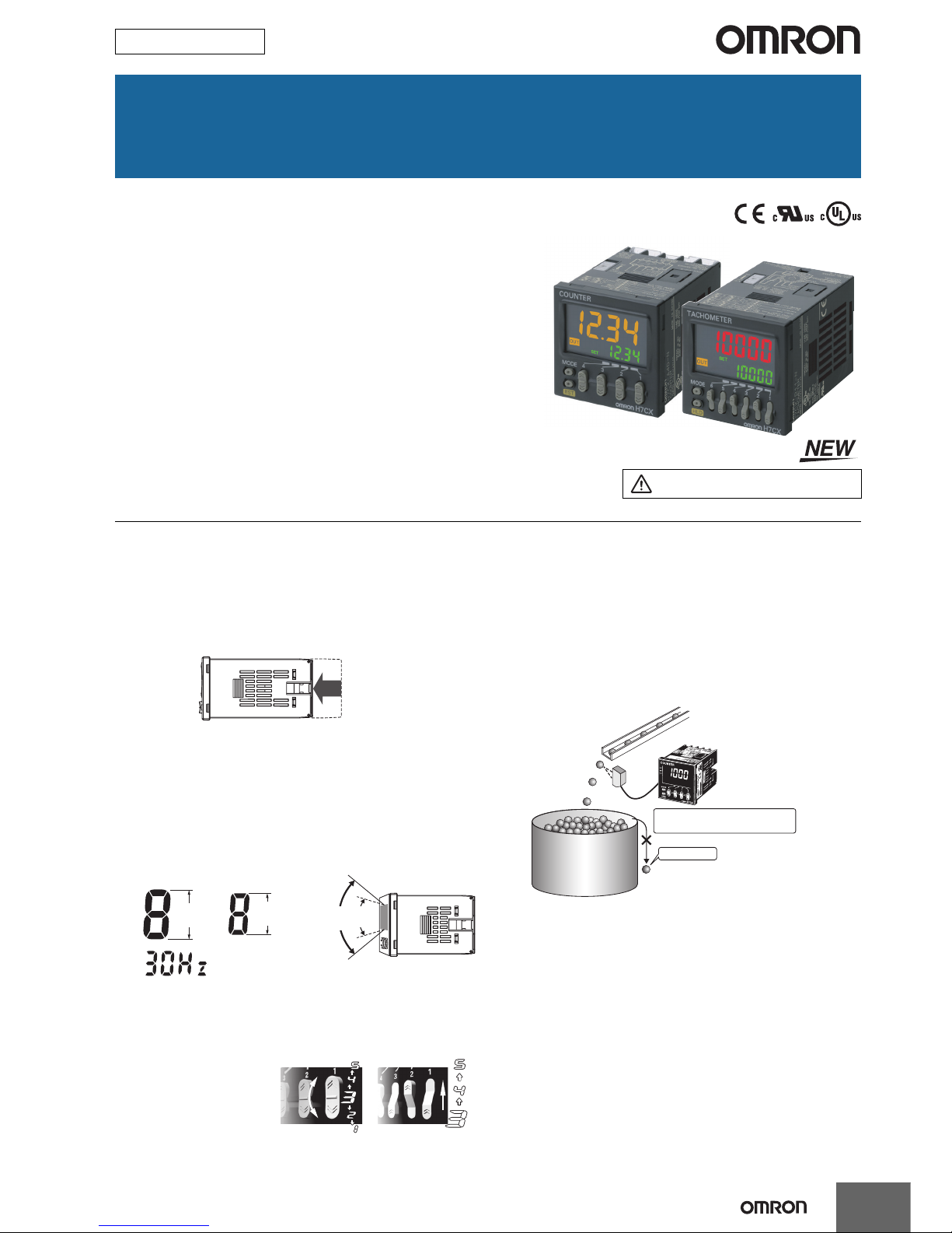
Ultra Short Body
The body depth has been greatly reduced. Helps in making thinner
control panels.
Easier to Read
For better readability, the character height for the present value
display is 12 mm on models with 4 digits, the largest class in the
industry. The wide viewing angle and brightness provide excellent
visibility. The number of display segments has also been increased to
make settings easier to understand, and the present value display
can be switched between red, green, and orange so that output status
can be seen from a distance.
Note: The display color can be switched on all models except for the
H7CX-A11 and H7CX-R11.
The Easiest Operation
Operation is simplified by the
Up/Down Key for each digit
on 4-digit models and Up
Key for each digit on 6-digit
models.
Safety and Reliability
Isolated Power Supply and Input Circuits
Power supply circuit and input circuits are isolated inside the Counter/
Tachometer. Previous non-isolated counters had wiring restrictions
and could be damaged if wired incorrectly. The H7CX removes these
worries.
Note: Except 12 to 24-VDC models.
Set Value Limit
You can set an upper limit for the set value to prevent unexpected
operation of output devices caused by setting mistakes.
Output Counter
The output counter counts the number of times the output turns ON
(alarms can be displayed and the count can be monitored in
increments of 1,000 operations). This counter is useful in managing
the service life of the Counter/Tachometer or the load.
Refer to Safety Precautions on page 52.
12 to 24-VDC Models with Screw Terminals: 59 mm
100 to 240-VAC Models with Screw Terminals: 78 mm*
Models with Sockets: 63.7 mm (case dimension)
* Power supply circuit and input circuits are isolated for safety and rel iability.
New models
Previous
models
12 mm
(actual size)
Model with 4 Digits Model with 6 Digits
10 mm
(actual size)
(Display example)
New
models
Previous
models
Easy to read from the top, bottom,
and sides!
Model with 4 Digits Model with 6 Digits
For 1,000 pieces
No overflow
Setting the upper limit of the set
value enables worry-free operation.
Page 2
2
H7CX-@-N
Other Features
The front color can be changed simply by
replacing the Front Panel.
The Front Panel can be replaced with an optional Front Panel (sold
separately) with a different color to match the installation site. Select
from black, white, and light gray (except for models with tachometer
function only).
Universal NPN/PNP Input
DC 2-wire sensors can be connected for a wide range of input
devices.
Waterproof, Dust-proof Structure (UL508 Type
4X and IP66)
Worry-free application is possible in locations subject to water.
Note: When the Y92S-29 Waterproof Packing is used.
Key Protection
Select from any of seven protection patterns. Use the best one for the
application.
New Functions
Many useful functions have been added, including a Twin Counter
Mode and many tachometer functions to handle even more
applications.
New Tachometer Functions
• Control with two independent inputs (independent measurements,
differential, absolute ratio, and error ratio)
• Peak/bottom hold function
• Output hysteresis setting
• Output OFF delay
• Switching the measurement method (pulse cycle/pulse width)
• Startup time
• Auto-zero time
• Averaging method/Number of averaging times
• AMD-compatible Mode
Model Number Structure
Model Configuration
*1. Set the tachometer input mode from the function setting mode to switch to the tachometer function.
White
Light gray
Black
(Standard)
Only the Front
Panel can be
replaced.
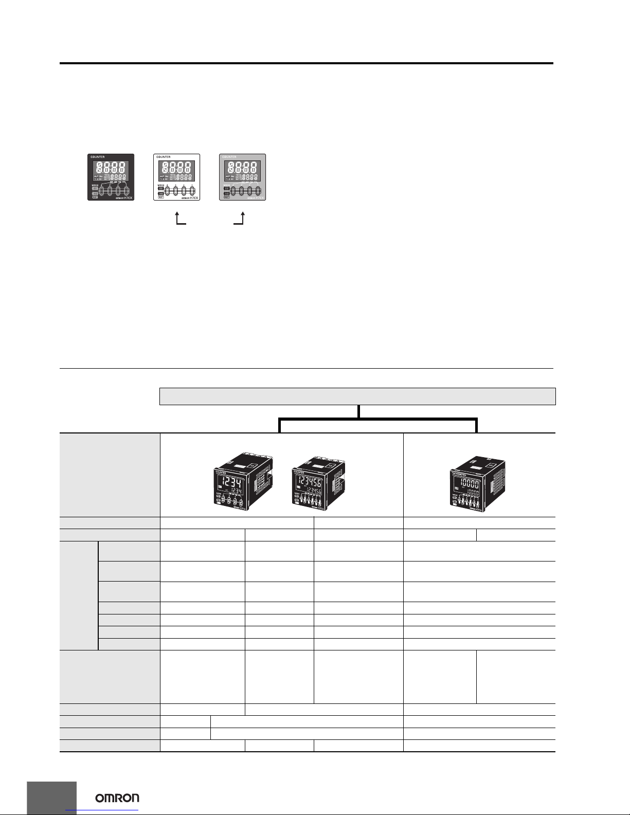
H7CX Series
Model
H7CX-A-series Multifunction Preset Counter H7CX-R-series Digital Tachometer
Classification Preset counter Preset counter/tachometer Tachometer
Model H7CX-A@-N H7CX-A4W@-N H7CX-AW@-N/-AU@-N H7CX-R11@-N H7CX-R11W@-N
Function
1-stage preset
counter
Yes Yes Yes No
2-stage preset
counter
No Yes Yes No
Total and preset
counter
Yes Yes Yes No
Batch counter No Yes Yes No
Dual counter No Yes Yes No
Twin counter No Yes Yes No
Tachometer No No Yes
*1
Yes
Tachometer input No No
Yes
1 input or 2 inputs
(independent
measurements, differential,
absolute ratio value, and
error ratio value)
Yes
1 input
Yes
2 inputs (independent
measurement) only
Settings 1-stage 2-stage 1-stage
External connections 11-pin socket Screw terminals 11-pin socket
Display color of present value Red Red, green, or orange Red
Display digits 4 or 6 digits 4 digits 6 digits 6 digits
Page 3
H7CX-@-N
3
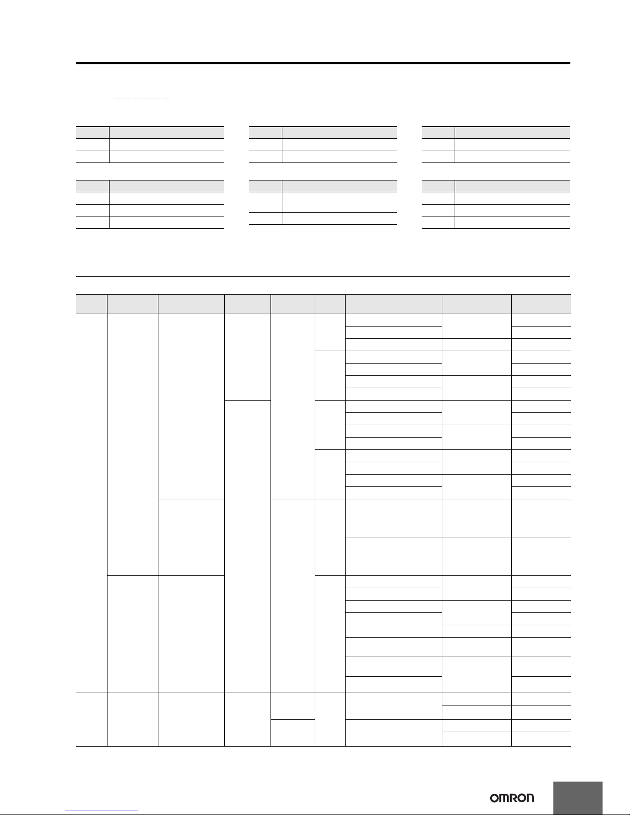
Model Number Legend (Not all possible combinations of functions are available.)
H7CX-@@@@@@-N
123 456
Ordering Information
List of Models
Note: 1. The functions that are provided depend on the model. Check detailed specifications before ordering.
2. Refer to page page 37 and later for information on H7CX-R Tachometers.
Type Classification Configuration
External
connections
Settings
Display
digits
Outputs
Power supply
voltage
Model
H7CX-A
Series
Preset counter
• 1-stage preset
counter
• Total and preset
counter
11-pin socket
1-stage
4 digits
Contact output (SPDT)
100 to 240 VAC
H7CX-A114-N
Transistor output (SPST) H7CX-A114S-N
Contact output (SPDT) 12 to 24 VDC/24 VAC H7CX-A114D1-N
6 digits
Contact output (SPDT)
100 to 240 VAC
H7CX-A11-N
Transistor output (SPST) H7CX-A11S-N
Contact output (SPDT)
12 to 24 VDC/24 VAC
H7CX-A11D1-N
Transistor output (SPST) H7CX-A11SD1-N
Screw
terminals
4 digits
Contact output (SPDT)
100 to 240 VAC
H7CX-A4-N
Transistor output (SPST) H7CX-A4S-N
Contact output (SPDT)
12 to 24 VDC
H7CX-A4D-N
Transistor output (SPST) H7CX-A4SD-N
6 digits
Contact output (SPDT)
100 to 240 VAC
H7CX-A-N
Transistor output (SPST) H7CX-AS-N
Contact output (SPDT)
12 to 24 VDC
H7CX-AD-N
Transistor output (SPST) H7CX-ASD-N
• 1-stage preset
counter
• 2-stage preset
counter
• Total and preset
counter
• Batch counter
• Dual counter
• Twin counter
2-stage
4 digits
Contact output (SPST + SPDT) 100 to 240 VAC H7CX-A4W-N
Transistor output (DPST) 12 to 24 VDC H7CX-A4WSD-N
Preset counter/
Tachometer
• 1-stage preset
counter
• 2-stage preset
counter
• Total and preset
counter
• Batch counter
• Dual counter
• Twin counter
• Tachometer
6 digits
Contact output (SPST + SPDT)
100 to 240 VAC
H7CX-AW-N
Transistor output (DPST) H7CX-AWS-N
Contact output (SPST + SPDT)
12 to 24 VDC/24 VAC
H7CX-AWD1-N
Transistor output (DPST)
H7CX-AWSD1-N
12 to 24 VDC H7CX-AWSD-N
Contact output (SPDT) +
Transistor output (SPST)
100 to 240 VAC H7CX-AU-N
Contact output (SPDT) +
Transistor output (SPST)
12 to 24 VDC/24 VAC
H7CX-AUD1-N
Transistor output (DPST) H7CX-AUSD1-N
H7CX-R
Series
Tachometer • Tachometer 11-pin socket
1-stage
(1 input and
output)
6 digits
Contact output (SPDT)
100 to 240 VAC H7CX-R11-N
12 to 24 VDC/24 VAC H7CX-R11D1-N
1-stage
(2 inputs and
outputs)
Contact output (SPDT + SPST)
100 to 240 VAC H7CX-R11W-N
12 to 24 VDC/24 VAC H7CX-R11WD1-N
4. Settings
* The H7CX-R11W@ is a 1-stage (2 inputs and outputs)
rather than a 2-stage Counter.
5. Output type 6. Supply voltage
Symbol Meaning
None 1-stage setting
U Factory-set to 1-stage setting
W Factory-set to 2-stage setting*
Symbol Meaning
None
Contact output or contact output +
transistor output
S Transistor output
Symbol Meaning
None 100 to 240 VAC at 50/60 Hz
D 12 to 24 VDC
D1 12 to 24 VDC/24 VAC at 50/60 Hz
1. Type 2. External connections 3. Digits
Symbol Meaning
A Standard type
R Tachometer
Symbol Meaning
None Screw terminals
11 11-pin socket
Symbol Meaning
None 6 digits
4 4 digits
Page 4
4
H7CX-@-N
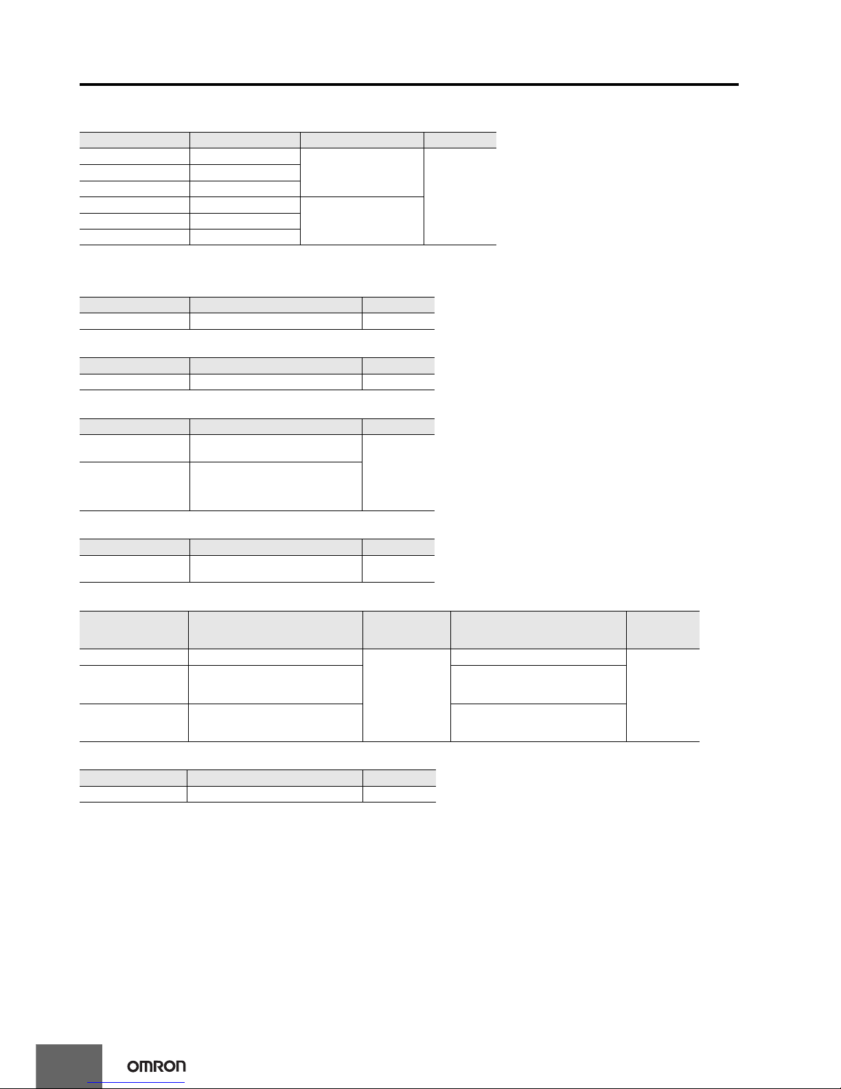
Accessories (Order Separately)
Front Panels (Replacement Part)
Note: 1. You can change the color of the Front Panel when mounting the Counter. The Counter is shipped with a black (N1.5) Front Panel.
2. "COUNTER" is printed on the front of Replacement Front Panels.
Soft Cover
Hard Cover
Flush Mounting Adapter
Waterproof Packing
Connection Sockets
Terminal Covers for P3GA-11 Back-connecting Socket
Model Color Applicable Counters Page
Y92P-CXC4G Light gray (5Y7/1) 4-digit Counter
12
Y92P-CXC4S White (5Y9.2/0.5)
Y92P-CXC4B Black (N1.5)
Y92P-CXC6G Light gray (5Y7/1) 6-digit Counter
Y92P-CXC6S White (5Y9.2/0.5)
Y92P-CXC6B Black (N1.5)
Model Remarks Page
Y92A-48F1 --- 12
Model Remarks Page
Y92A-48 --- 12
Model Remarks Page
Y92F-30
Included with models with screw
terminals.
12
Y92F-45
Use this Adapter to install the Counter/
Tachometer in a cutout previously made
for a DIN 72 × 72 mm device (panel
cutout: 68 × 68 mm).
Model Remarks Page
Y92S-29
Included with models with screw
terminals.
12
Model Classification
Connectable
Counter/
Tachometers
Remarks Page
P2CF-11 Front-connecting Socket
H7CX-@11@-N
---
13
P2CF-11-E
Front-connecting Socket (Finger-safe
Type)
Round crimp terminals cannot be used on
Finger-safe Sockets.
Use forked crimp terminals.
P3GA-11 Back-connecting Sockets
A Y92A-48G Terminal Cover can be used
with the Socket to create a finger-safe
construction.
Model Remarks Page
Y92A-48G --- 13
Page 5
H7CX-A@-N
5
• Easy to check the output status from a long distance with changing
display colors
*1
(red, green, and orange).
• Includes total and preset counter, batch counter, dual counter, twin
counter, and tachometer.
*2
*1. Not supported by the H7CX-A11@-N.
*2. The functions that can be selected depend on the model.
Specifications
Ratings
*1. 1-stage preset counter and total counter functionality.
*2. Do not use the output from an inverter as the power supply.The ripple must be 20% maximum for DC power.
*3. A response of 10 kHz is possible if the response speed is 5 kHz and the 1-stage preset counter input mode is increment, decrement, or increment/
decrement (command input).
*4. The display is lit only when the power is ON. Nothing is displayed when power is OFF.
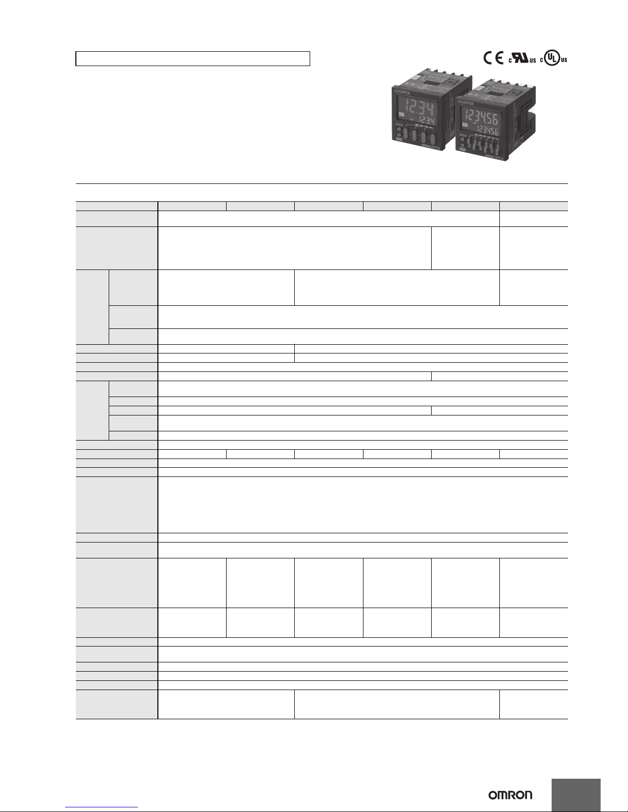
H7CX-A@-N Multifunction Preset Counter
Item Models H7CX-A114@-N H7CX-A11@-N H7CX-A4@-N H7CX-A@-N H7CX-A4W@-N H7CX-AW@-N/-AU@-N
Classification Pres et counter
Preset counter/
tachometer
Configuration 1-stage preset counter, 1-stage preset counter with total counter (selectable)*1
1-stage/2-stage preset
counter, total and preset
counter*1, batch
counter, dual counter,
and twin counter
(selectable)
1-stage/2-stage preset
counter, total and preset
counter*1, batch
counter, dual counter,
twin counter, and
tachometer (selectable)
Ratings
Power supply
voltage*2
• 100 to 240 VAC, 50/60 Hz
• 24 VAC, 50/60 Hz or 12 to 24 VDC
• 100 to 240 VAC, 50/60 Hz
•12 to 24 VDC
• 100 to 24 0 VAC at 50/
60 Hz
• 2 4 VAC at 50/60 Hz or
12 to 24 VDC
• 12 to 24 VDC
Operating voltage fluctuation
range
85% to 110% of rated supply voltage (12 to 24 VDC: 90% to 110%)
Power consumption
Approx. 9.4 VA at 100 to 240 VAC, Approx. 7.2 VA/4.7 W at 24 VAC/12 to 24 VDC, Approx. 3.7 W at 12 to 24 VDC
Mounting method Flush mounting or surface mounting Flush mounting
External connections 11-pin socket Screw terminals
Degree of protection IEC IP66, UL508 Type 4X (indoors) for panel surface only and only when Y92S-29 Waterproof Packing is used.
Input signals CP1, CP2, reset, and total reset CP1, CP2, reset 1, and reset 2
Counter
Maximum
counting speed
30 Hz or 5 kHz (switchable) (ON/OFF ratio 1:1)*3
*Common setting for CP1 and CP2
Input mode Increment, decrement, increment/decrement (UP/DOWN A (command input), UP/DOWN B (individual inputs), or UP/DOWN C (quadrature inputs))
Output mode N, F, C, R, K-1, P, Q, A, K-2, D, and L. N, F, C, R, K-1, P, Q, A, K-2, D, L, and H.
One-shot output time
0.01 to 99.99 s
Reset system External (minimum reset signal width: 1 ms or 20 ms, selectable), manual, and automatic reset (internal according to C, R, P, and Q mode operation)
Tachometer Refer to the separate table for tachometer function ratings.
Prescaling function Yes (0.001 to 9.999) Yes (0.001 to 99.999) Yes (0.001 to 9.999) Yes (0.001 to 99.999) Yes (0.001 to 9.999) Yes (0.001 to 99.999)
Decimal point adjustment Yes (rightmost 3 digits)
Sensor waiting time 290 ms max. (Control output is turned OFF and no input is accepted during sensor waiting time.)
Input method
No-voltage inputs:
ON impedance: 1 kΩ max. (Leakage current: 12 mA at 0 Ω)
ON residual voltage: 3 V max.
OFF impedance: 100 kΩ min.
Voltage input:
High (logic) level: 4.5 to 30 VDC
Low (logic) level: 0 to 2 VDC (Input resistance: approx. 4.7 kΩ)
No-voltage input/voltage input (switchable)
External power supply 12 VDC (±10%), 100 mA (except for H7CX-A@D models) Refer to Precautions for Correct Use on page page 53 for details.
Control output
• Contact output: 3 A at 250 VAC/30 VDC, resistive load (cosφ=1), Minimum applied load: 10 mA at 5 VDC (failure level: P, reference value)
• Transistor output: NPN open collector, 100 mA at 30 VDC, Residual voltage: 1.5 VDC max. (approx. 1 V), Leakage current: 0.1 mA max.
Display*4
7-segment, negative
transmissive LCD
Character height
Count value: 12 mm
(red)
Set value: 6 mm (green)
7-segment, negative
transmissive LCD
Character height
Count value: 10 mm
(red)
Set value: 6 mm (green)
7-segment, negative
transmissive LCD
Character height
Count value: 12 mm
(red, green, or orange
selectable)
Set value: 6 mm (green)
7-segment, negative
transmissive LCD
Character height
Count value: 10 mm
(red, green, or orange
selectable)
Set value: 6 mm (green)
7-segment, negative
transmissive LCD
Character height
Count value: 12 mm
(red, green, or orange
selectable)
Set value: 6 mm (green)
7-segment, negative
transmissive LCD
Character height
Count value: 10 mm
(red, green, or orange
selectable)
Set value: 6 mm (green)
Digits
4 digits
−999 to 9999
(−3 digits to +4 digits)
6 digits
−99999 to 999999
(−5 digits to +6 digits)
4 digits
−999 to 9999
(−3 digits to +4 digits)
6 digits
−99999 to 999999
(−5 digits to +6 digits)
4 digits
−999 to 9999
(−3 digits to +4 digits)
6 digits
−99999 to 999999
(−5 digits to +6 digits),
tachometer: 0 to 999999
Memory backup EEPROM (overwrites: 100,000 times min.) that can store data for 10 years min.
Operating temperature
range
−10 to 55°C (−10 to 50°C if Counter/Tachometers are mounted side by side) (with no icing or condensation)
Storage temperature range −25 to 70°C (with no icing or condensation)
Operating humidity range 25% to 85%
Case color Black (N1.5) (Optional Front Panels are available to change the Front Panel color to light gray or white.)
Attachments --- Flush mounting adapter, waterproof packing, terminal cover
Flush mounting adapter,
waterproof packing,
terminal cover, label for
DIP switch settings
Page 6
6
H7CX-A@-N
Tachometer Function Ratings
* An input OFF time of at least 20 ms is required.
Characteristics
Model
Item
H7CX-A114@-N
H7CX-A11@-N
H7CX-A4@-N
H7CX-A@-N
H7CX-A4W@-N
H7CX-AW@-N/-AU@-N
Input mode
No tachometer
functionality
Selectable from independent measurements for 1 or 2 inputs, differential input for 2 inputs, absolute ratio for 2 inputs, and
error ratio for 2 inputs.
Pulse measurement method Periodic measurement Pulse width measurement
Maximum counting speed 30 Hz
1-input mode: 10 kHz
Other modes: 5 kHz
30 Hz
1-input mode: 10 kHz
Other modes: 5 kHz
Minimum input signal width --- --- 30 ms
*1
1-input mode: 0.2 ms
Other modes: 0.4 ms*
Measuring ranges 0.01 to 30.00 Hz
1-input mode: 0.01 to 10 kHz,
Other modes: 0.01 to 5 kHz
0.030 to 999999 s
1-input mode: 0.0002 to 99999 s
Other modes: 0.0004 to 99999 s
Sampling period 200 ms min.
200 ms min. or continuous
selectable (minimum interval of 10
ms)
Continuous (minimum interval of 10 ms)
Measuring accuracy ±0.1% FS ±1 digit max. (at 23 ±5°C)
Output mode
Input mode:
Not 2-input independent measurement: HI-LO, AREA, HI-HI, LO-LO
2-input independent measurement: HI-HI, LO-LO
Auto-zero time 0.1 to 999.9s
Startup time 0.0 to 99.9s
Averaging Simple averaging/moving averaging selectable, Processing: OFF, 2, 4, 8, or 16 times
Hold input Minimum input signal width: 20 ms
* Refer to the Life-test Curve.
Applicable Standards
* The following safety standards apply to models with sockets (H7CX-A11@ or H7CX-A114@).
cUL (Listing): Applicable when an OMRON P2CF(-E) Socket is used.
cUR (Recognition): Applicable when any other socket is used.
Insulation resistance
100 MΩ min. (at 500 VDC) between current-carrying terminals and exposed non-
current-carrying metal parts, and between non-continuous contacts
Dielectric strength
2,000 VAC, 50/60 Hz for 1 min between current-carrying metal parts and noncurrent-carrying metal parts
2,000 VAC, 50/60 Hz for 1 min between power supply and input circuit for all models
except H7CX-@D@ (1,000 VAC for 24 VAC/12 to 24 VDC)
1,000 VAC (for H7CX-@SD@), 50/60 Hz for 1 min between control output, power
supply, and input circuit (2,000 VAC for models other than H7CX-@SD@)
1,000 VAC, 50/60 Hz for 1 min between non-continuous contacts
Impulse withstand voltage
3.0 kV between power terminals (1.0 kV for models with 24 VAC/12 to 24 VDC or 12
to 24 VDC)
4.5 kV between current-carrying terminals and exposed non-current-carrying metal
parts (1.5 kV for models with 24 VAC/12 to 24 VDC or 12 to 24 VDC)
Noise immunity
±1.5 kV between power terminals (±480 V for models with 12 to 24 VDC)
±600 V between input terminals
Square-wave noise by noise simulator (pulse width: 100 ns/1 µs, 1-ns rise)
Static immunity
Malfunction: 8 kV
Destruction: 15 kV
Vibration
resistance
Destruction 10 to 55 Hz with 0.75-mm single amplitude each in three directions for 2 h each
Malfunction 10 to 55 Hz with 0.35-mm single amplitude each in three directions for 10 min each
Shock resistance
Destruction 300 m/s2 each in three directions
Malfunction 100 m/s2 each in three directions
Life expectancy
Mechanical: 10,000,000 operations min.
Electrical: 100,000 operations min. (3 A at 250 VAC, resistive load, ambient
temperature condition: 23°C)*
Weight Approx. 130 g (Counter only)
Approved
safety
standards
cULus (or cURus): UL508/CSA C22.2 No. 14*
EN 61010-1 (IEC 61010-1): Pollution degree 2/overvoltage category II
B300 PILOT DUTY
1/4 HP 120 VAC, 1/3 HP, 240 VAC, 3 A resistive load
VDE0106/P100 (finger protection)
EMC
(EMI) EN61326
Emission Enclosure: EN 55011 Group 1 class A
Emission AC mains: EN 55011 Group 1 class A
(EMS) EN61326
Immunity ESD: EN 61000-4-2: 4 kV contact discharge;
8 kV air discharge
Immunity RF-interference: EN 61000-4-3: 10 V/m (Amplitude-modulated, 80 MHz to 1
GHz);
10 V/m (Pulse-modulated, 900 MHz ±5 MHz)
Immunity Conducted Disturbance: EN 61000-4-6: 10 V (0.15 to 80 MHz)
Immunity Burst: EN 61000-4-4: 2 kV power-line;
1 kV I/O signal-line
Immunity Surge: EN 61000-4-5: 1 kV line to lines (power and output lines);
2 kV line to ground (power and output lines)
Immunity Voltage Dip/Interruption: EN 61000-4-11: 0.5 cycle, 100% (rated voltage)
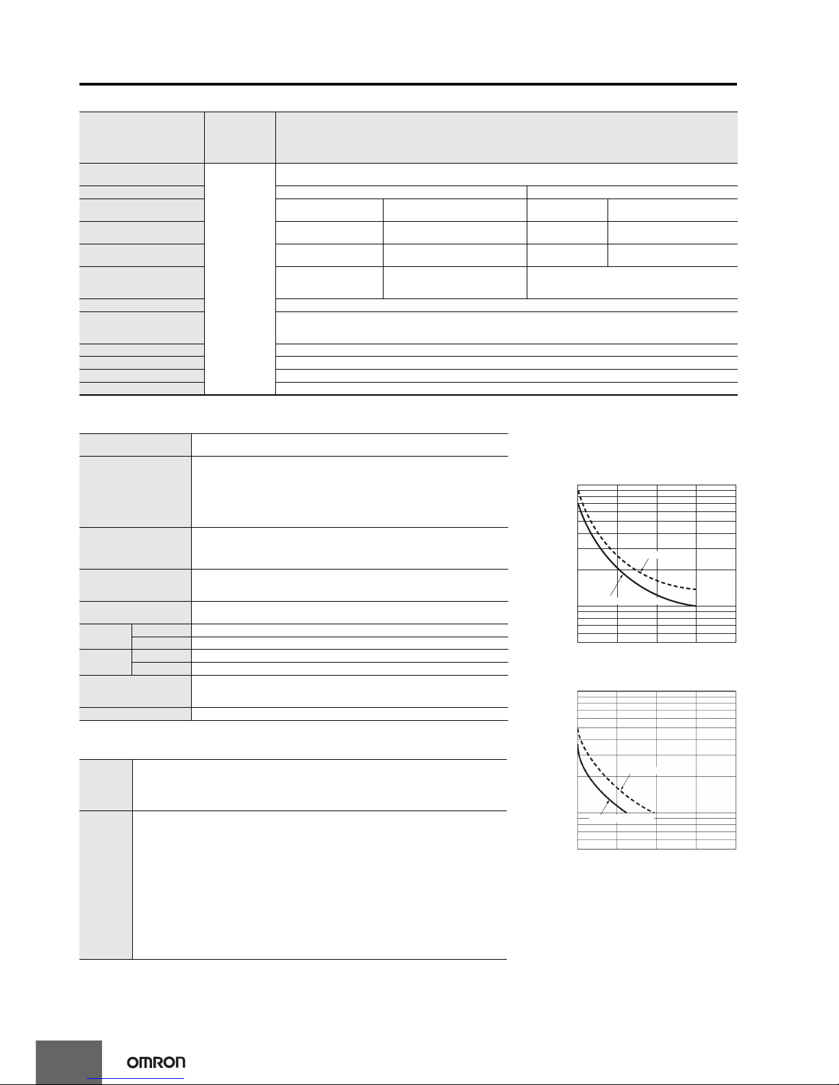
Life-test Curve (Reference
Values)
Resistive load
Inductive load
A current of 0.15 A max. can be switched at 125
VDC (cosφ=1) and current of 0.1 A max. can be
switched if L/R=7 ms. In both cases, a life of
100,000 operations can be expected.
1,000
700
500
300
100
70
50
Load current (A
)
01 2 34
30 VDC (cosφ=1)
250 VAC (cosφ=1)
No. of operations (
×
10
3
)
1,000
700
500
300
100
70
50
01 2 34
30 VDC (L/R=7 ms)
Load current (A)
250 VAC (cosφ=1)
No. of operations (
×
10
3
)
Page 7
H7CX-A@-N
7
I/O Functions
Using as a Counter
*1
*1. For information on operation of I/O functions, refer to pages page 22 to page 25.
*2. In increment mode or increment/decrement mode, the present value returns to 0; in decrement mode, the present value returns to the set value with 1-stage models,
and returns to set value 2 with 2-stage models.
*3. Reset operates as described in the following table. (The reset indicator will not be lit.)
• The following table shows the delay from when the reset signal is input until the output is turned OFF. (Reference values)
Operating Procedures (Tachometer Function)
Inputs
CP1, CP2
(1) In general (except for Dual Counter Mode)
• Reads counting signals.
• Increment, decrement, command, individual, and quadrature inputs accepted.
(2) When used as a dual counter or twin counter
• Reads CP1 count signals with CP1 input and CP2 count signals with CP2 input.
• Increment signals can be input.
Reset/reset 1
(1) In general (except for Dual Counter Mode)
• Resets present value and outputs (OUT2 when using the batch counter)*2.
• Counting cannot be performed during reset/reset 1 input.
• Reset indicator is lit while reset input is ON.
(2) When used as a dual counter or twin counter.
• Resets the CP1 present value (to 0).
• Counting for CP1 input cannot be performed while the reset 1 input is ON.
• The reset indicator is lit while the reset 1 input is ON.
Total reset or reset 2 The reset function depends on the selected configuration*3.
Outputs OUT1, OUT2 Outputs signals according to the specified output mode when a set value is reached.
Configuration Reset operation
1-stage/2-stage
preset counter
Does not operate (not used).
Total and preset
counter
• Resets the total count value.
• The total count value is held at 0 while the total reset input is ON.
Batch counter
• Resets the batch count value and batch output (OUT1).
• The batch count value is held at 0 while the reset 2 input is ON.
Dual counter
• Resets the CP2 present value.
• Counting for CP2 input cannot be performed while the reset 2 input is ON.
Twin counter • Resets the CP2 present value.
Minimum reset signal width Output delay time
1 ms 0.8 to 1.2 ms
20 ms 15 to 25 ms
Inputs
CP1, CP2 Reads counting signals. (The CP2 input can be used when the input mode is not 1-input mode.)
Reset/reset 1
• Holds the measurement value and outputs. (The reset 2 input can be used when the input mode
is 2-input independent measurement.)
• The reset indicator is lit when the value is being held.
Outputs OUT1, OUT2 Outputs signals according to the specified output mode when a set value is reached.
Page 8
H7CX-A@-N
8
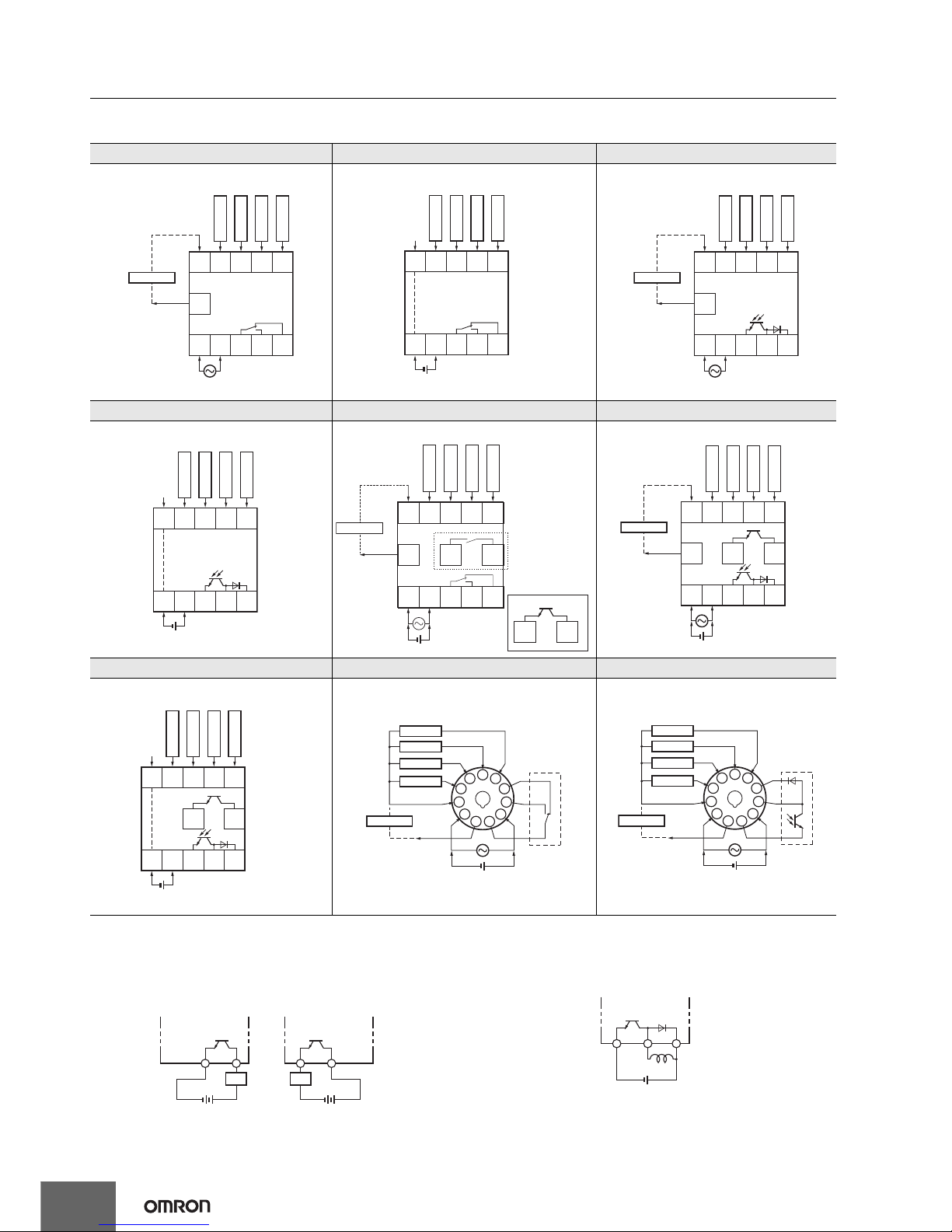
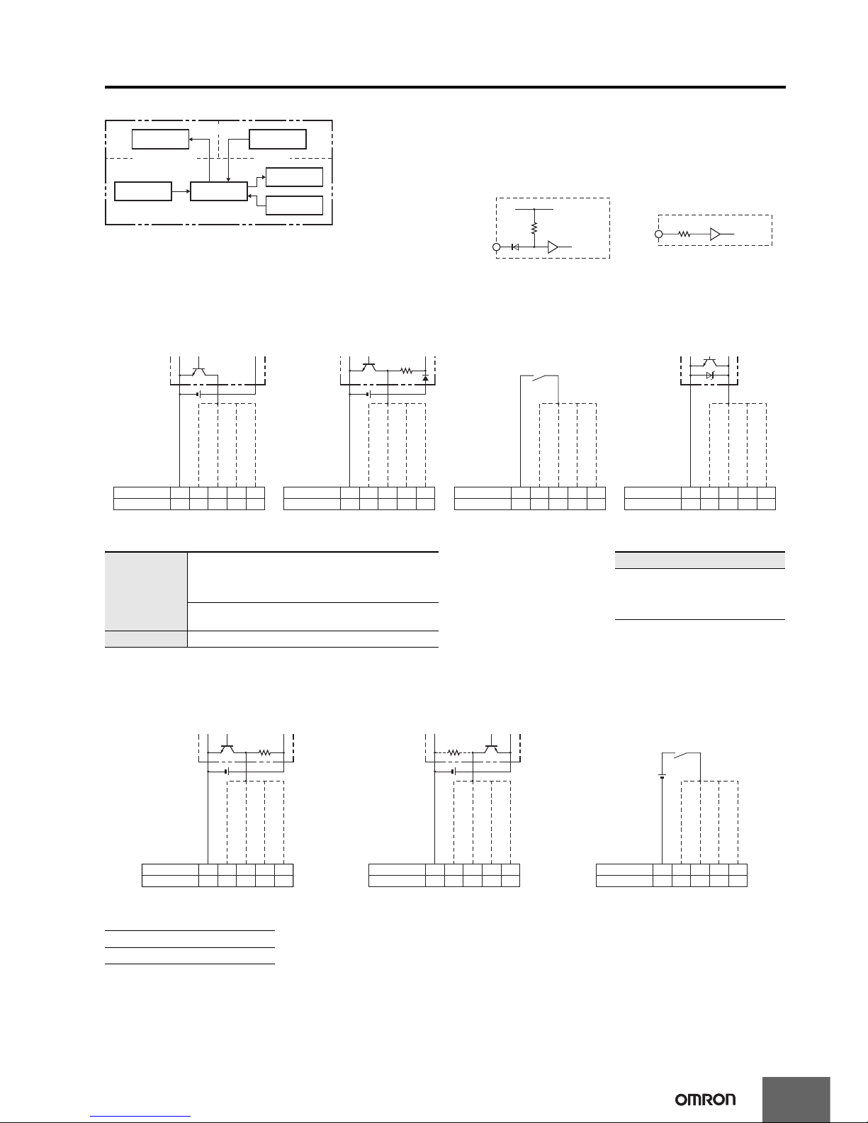
Connections
Terminal Arrangement
Confirm that the power supply meets specifications before use.
Transistor Output
• The transistor output of the H7CX is isolated from the internal
circuitry by a photocoupler, so the transistor output can be used as
both NPN and PNP output.
• The diode connected to the collector of the output transistor is used
to absorb inverted voltage that is generated when an inductive load
is connected to the H7CX.
H7CX-A-N/-A4-N H7CX-AD-N/-A4D-N H7CX-AS-N/-A4S-N
1-stage Contact Output 1-stage Contact Output
Terminals 1 and 6 are connected internally.
1-stage Transistor Output
H7CX-ASD-N/-A4SD-N H7CX-AW-N/-A4W-N/-AWD1-N/-AU-N/-AUD1-N H7CX-AWS-N/-AWSD1-N/-AUSD1-N
1-stage Transistor Output
Terminals 1 and 6 are connected internally.
2-stage Contact Output 2-stage Transistor Output
H7CX-AWSD-N/-A4WSD-N H7CX-A11-N/-A114-N/-A11D1-N/-A114D1-N H7CX-A11S-N/-A114S-N/-A11SD1-N
2-stage Transistor Output
Terminals 1 and 6 are connected internally.
1-stage Contact Output 1-stage Transistor Output
678910
11
OUT
(−)
(+)
0 V
12345
Reset
Total reset
CP2
CP1
Sensor
12 VDC
External
power supply
678910
OUT
(+)
(−)
0 V
12345
Reset
Total reset
CP2
CP1
678910
11
12345
OUT
0 V
(−)
(+)
Reset
Total reset
CP2
CP1
Sensor
12 VDC
External
power supply
678910
0 V
12345
OUT
(+)(−)
Reset
CP2
CP1
Total reset
678910
11 12 13
OUT1
12345
OUT2
(+)(−)
0 V
(−)
(+)
Reset 1
CP2
CP1
12 VDC
External
power supply
Reset 2
Sensor
12 13
*
1
1: “-AU@” Models
*
*
678910
11 12 13
12345
OUT1
OUT2
0 V
(+)(−)
(−)
(+)
Reset 1
CP2
CP1
Sensor
12 VDC
External
power supply
Reset 2
678910
12 13
0 V
12345
OUT1
OUT2
(+)(−)
Reset 1
CP2
CP1
Reset 2
6
7
8
9
10
11
1
2
3
4
5
(+)
(−)
OUT
0 V
(−)
(+)
Reset
Total reset
CP2
CP1
Sensor
12 VDC
External
power supply
Internal circui
t
6
7
8
9
10
11
1
2
3
4
5
0 V
OUT
(+)(−)
(−)
(+)
Reset
Total reset
CP2
CP1
Sensor
12 VDC
External
power supply
Internal circui
t
Power for load
+
Load
Power for load
+
Load
NPN Output PNP Output
Power for load
+
Counter
Inductive
load
Page 9
H7CX-A@-N
9
Block Diagram
Note: All models except for H7CX-@D-N have basic insulation.
Input Circuits
CP1, CP2, Reset/Reset 1, and Total Reset/Reset 2
Input
Input Connections
The inputs of the H7CX-@-N are no-voltage (short-circuit or open) inputs or voltage inputs.
No-voltage Inputs (NPN Inputs)
No-voltage Input Signal Levels
Note: The DC voltage must be 30 VDC max.
Voltage Inputs (PNP Inputs)
Voltage Input Signal Levels
Note: 1. The DC voltage must be 30 VDC max.
2. Input resistance: Approx. 4.7 kΩ
Output circuit
(See note.)
Display circuit
Input circuits
(Basic insulation)
(Basic insulation)
Internal
control circuit
Power supply
circuit
Key switch
circuit
No-voltage Inputs
(NPN Inputs)
Voltage Inputs (PNP Inputs)
Internal
circuit
IN
+14V
1 kΩ
IN
Approx. 4.7 kΩ
Internal
circuit
Open Collector Voltage Output Contact Input DC Two-wire Sensor
H7CX-A@
H7CX-A11@
Note: Operates with transistor ON.
PLC or
sensor
678910
37564
0 V for inputs
Reset/reset 1 input
CP2 input
CP1 input
Total reset/reset 2 input
H7CX-A@
H7CX-A11@
Note: Operates with transistor ON.
Sensor
678910
37564
0 V for inputs
Reset/reset 1 input
CP2 input
CP1 input
Total reset/reset 2 input
Note: Operates with relay ON.
H7CX-A@
H7CX-A11@
678910
37564
0 V for inputs
Reset/reset 1 input
CP2 input
CP1 input
Total reset/reset 2 input
Note: Operates with transistor ON.
H7CX-A@
H7CX-A11@
678910
37564
0 V for inputs
Reset/reset 1 input
CP2 input
CP1 input
Total reset/reset 2 input
No-contact input
Short-circuit level (transistor ON)
• Residual voltage: 3 V max.
• Impedance when ON: 1 kΩ max.
(The leakage current is approx. 12 mA when the impedance is 0 Ω.)
Open level (transistor OFF)
• Impedance when OFF: 100 kΩ min.
Contact input Use contacts which can adequately switch 5 mA at 10 V.
Applicable Two-wire Sensor
• Leakage current: 1.5 mA max.
• Switching capacity: 5 mA min.
• Residual voltage: 3 VDC max.
• Operating voltage: 10 VDC
No-contact Input (NPN Transistor) No-contact Input (PNP Transistor) Contact Input
Note: Operates with transistor OFF.
H7CX-A@
H7CX-A11@
Sensor
678910
37564
0 V for inputs
Reset/reset 1 input
CP2 input
CP1 input
Total reset/reset 2 input
Note: Operates with transistor ON.
H7CX-A@
H7CX-A11@
Sensor
678910
37564
0 V for inputs
Reset/reset 1 input
CP2 input
CP1 input
Total reset/reset 2 input
Note: Operates with relay ON.
H7CX-A@
H7CX-A11@
678910
37564
0 V for inputs
Reset/reset 1 input
CP2 input
CP1 input
Total reset/reset 2 input
High level (input ON): 4.5 to 30 VDC
Low level (input OFF): 0 to 2 VDC
Page 10
10
H7CX-A@-N
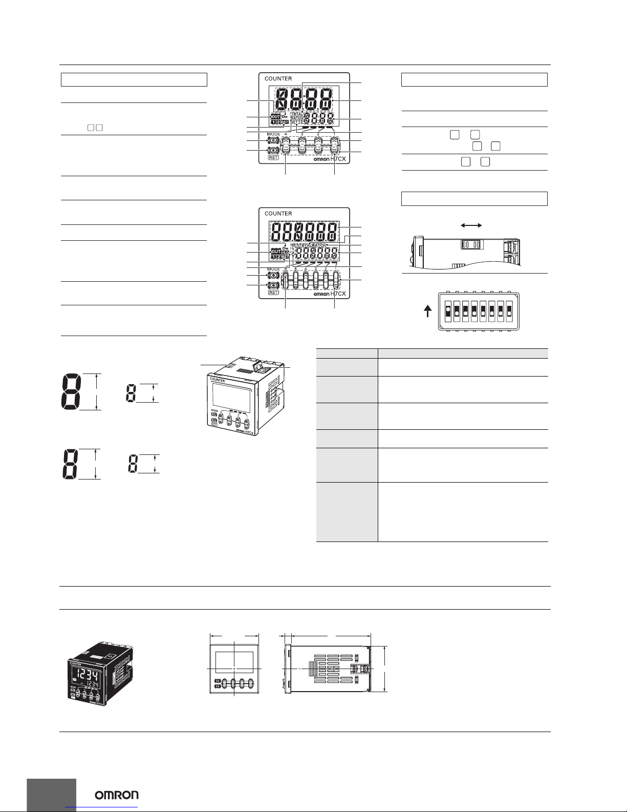
Nomenclature
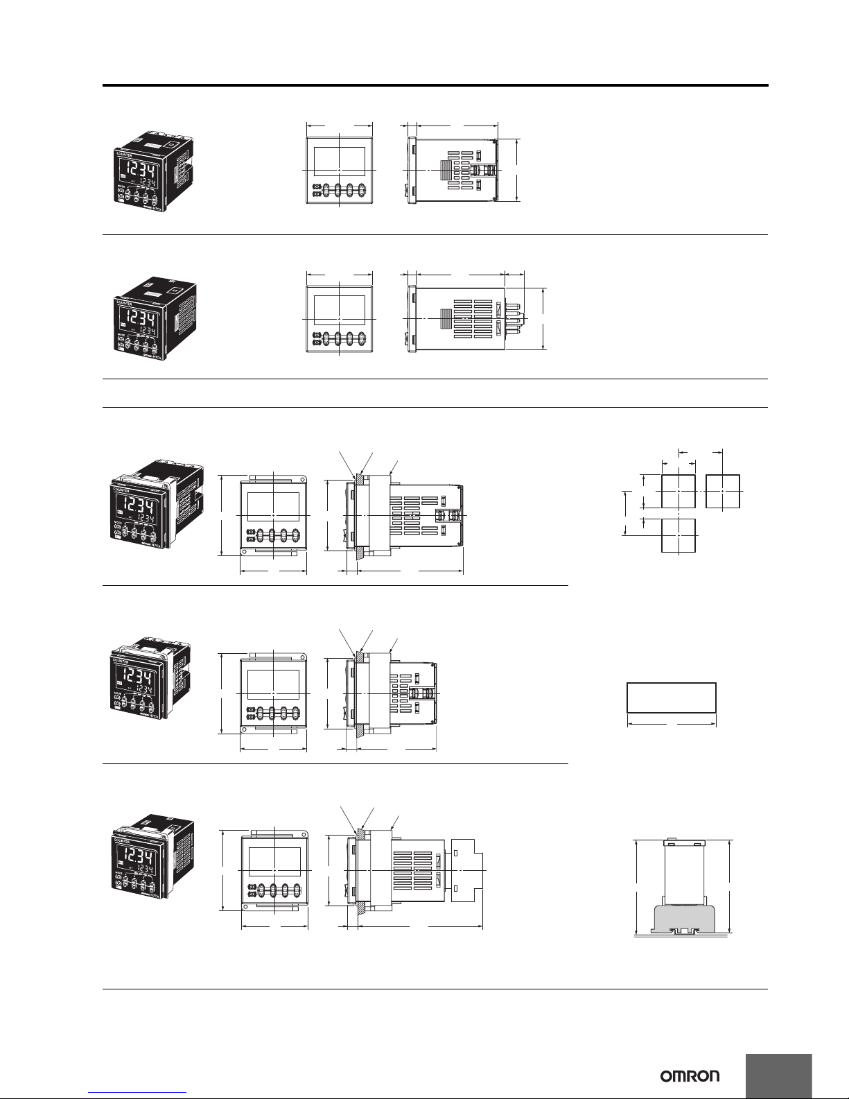
Dimensions (Unit: mm)
Counters
ON
(Enable)
(Default setting) OFF
(Disable)
RST
11
10
9
10
11
8
6
7
4
12
13
8
6
7
12
5
4
1st digit4th digit
1st digit6th digit
1
1
2
2
3
3
5
1 4
1
1 2
4
Display Section
3. Reset Indicator (orange)
1. Key Protect Indicator (orange)
2. Control Output Indicator (orange)
4. Total Count Indicator
6. Set Value 1, 2 Stage Indicator
8. Set value (Sub-display)
(Character height: 6 mm, green)
9. Hold Display (orange)
OUT: (One-stage)
OUT: (Two-stage)
(Lit when the total count value is displayed.)
(Lit when the reset input (1) or Reset Key is ON.)
Displayed only when the configuration selection
mode is not tachometer mode.
5. Batch Indicator
(Lit when the batch count value is displayed.)
Operation Keys
10. Mode Key
(Changes modes and setting items.)
11. Reset Key (See note.)
12. Up Keys to
1 6
(6-digit models: to )
13. Down Keys to
Switches
14. Key-protect Switch
15. DIP Switch
7. Present Value (Main Display)
(Character height: 12 mm (6-digit: 10 mm), red*)
(Front view of 4-digit model)
(Front view of 6-digit model)
* Characters on models with screw terminals (H7CX-A11@)
can be switched between red, green, and orange.
Displayed only when the configuration selection
mode is not tachometer mode.
OFF
ON
12345678
Note: The reset functions depends on the selected configuration.
Configuration Reset operation
1-stage/2-stage
preset counter
Resets the present value and outputs.
Total and preset
counter
• Resets the present value and outputs.
• When the total count value is displayed, resets the
present value, the total count value, and outputs.
Batch counter
• Resets the present value and OUT2.
• When the batch count value is displayed, resets the
present value, the batch count value, and outputs.
Dual counter
Resets the CP1 present value, CP2 present value, dual
count value, and outputs.
Twin counter
Resets the CP1 present value and output 1 when the
CP1 present value is displayed.
Resets the CP2 present value and output 2 when the
CP2 present value is displayed.
Tachometer
Holds the measurement value and outputs (hold
function).
(When the input mode is 2-input independent
measurement, the CP1 measurement value display will
hold the CP1 measurement value and output 1 and the
CP2 measurement value display will hold the CP2
measurement value and output 2.)
14
1
5
Model with 4 Digits
6 mm
12 mm
Character Size
for Sub-display
Character Size
for Main Display
Model with 6 Digits
10 mm
6 mm
Character Size
for Sub-display
Character Size
for Main Display
44.8 × 44.8
78
48 × 48
6
H7CX-A-N/-AS-N/-AW-N/-AWS-N/-AWD1-N/-AWSD1-N/-A4-N/-A4S-N/-A4W-N/-AU-N/-AUD1-N/-AUSD1-N
(Flush Mounting Models)
Note: M3.5 terminal screw (effective length: 6 mm)
Page 11
H7CX-A@-N
11
Dimensions with Flush Mounting Adapter
48 × 48
44.8 × 44.8
59
6
H7CX-AD-N/-ASD-N/-AWSD-N/-A4D-N/-A4SD-N/-A4WSD-N (Flush Mounting Models)
Note: M3.5 terminal screw (effective length: 6 mm)
48 × 48
44.8 × 44.8
63.7
14.4
6
H7CX-A11-N/-A11S-N/-A11D1-N/-A11SD1-N/-A114-N/-A114S-N/-A114D1-N (Flush Mounting/Surface Mounting Models)
58
48
76.57.5
Panel
Y92F-30 (provided)
Flush Mounting Adapter
Y92S-29 (provided)
Waterproof Packing
(51)
H7CX-A-N/-AS-N/-AW-N/-AWS-N/-AWD1-N/-AWSD1-N/-A4-N/-A4S-N/-A4W-N
(Provided with Adapter and Waterproof Packing)
Panel Cutouts
Panel cutouts are as shown below. (according
to DIN43700).
Note: 1. The mounting panel thickness
should be 1 to 5 mm.
2. To allow easier operation, it is
recommended that Adapters be
mounted so that the gap between
sides with hooks is at least 15 mm
(i.e., with the panel cutouts
separated by at least 60 mm).
3. It is possible to mount counters
side by side, but only in the
direction without the hooks. If they
are mounted side-by-side, waterresistance will be lost.
Dimensions with Front
Connecting Socket
* These dimensions depend on the kind of DIN Track.
(Reference value)
60 min.
60 min.
15 min.
45
+
0.6
0
45
+
0.6
0
A
With Y92A-48F1 attached.
With Y92A-48 attached.
A=(48n−2.5)
+1
−0
A=(51n−5.5)
+1
−0
A={48n−2.5+(n−1)×4}
+1
−0
n Units mounted
side by side
103.2*
100.9
H7CX
-A11@
P2CF-11(-E) Front Connecting Socket
(order separately)
58
48
(51)
7.5 57.5
Panel
Y92F-30 (provided)
Flush Mounting Adapter
Y92S-29 (provided)
Waterproof Packing
H7CX-AD-N/-ASD-N/-AWSD-N/-A4D-N/-A4SD-N/-A4WSD-N
(Provided with Adapter and Waterproof Packing)
58
48
(51)
7.5 89.9
Panel
Y92F-30 (order separately)
Flush Mounting Adapter
Y92S-29 (order separately)
Waterproof Packing
H7CX-A11-N/-A11S-N/-A11D1-N/-A11SD1-N/-A114-N/-A114S-N/-A114D1-N
(Adapter and Waterproof Packing Ordered Separately)
Page 12
12
H7CX-A@-N
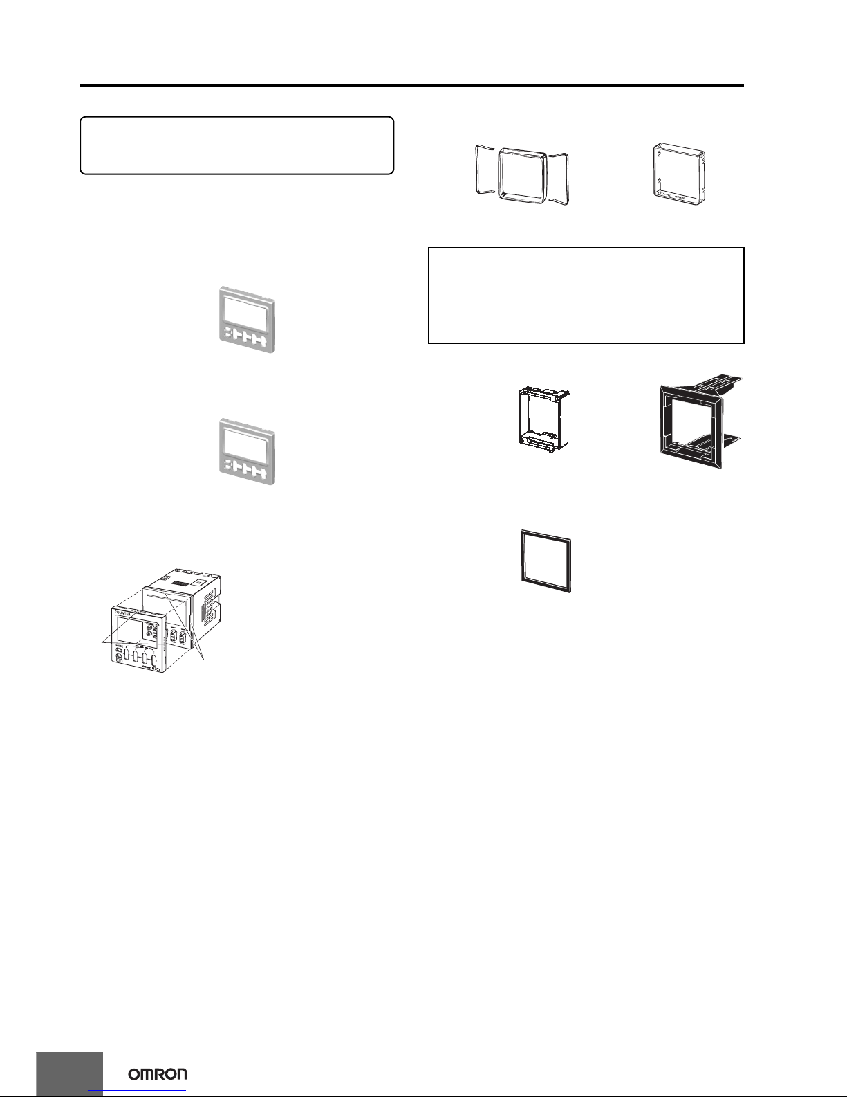
Accessories (Order Separately)
Front Panel (Replacement Part)
You can change the color of the Front Panel when mounting the
Counter/Tachometer. The Counter/Tachometer is shipped with a
black (N1.5) Front Panel. "COUNTER" is printed on the front of
Replacement Front Panels.
Protecting the Counter/Tachometer in Environments
Subject to Oil
The Waterproof Packing will deteriorate, harden, and shrink
depending on the application environment. To ensure maintaining the
IP@6, UL Type 4X waterproof level, periodically replace the
Waterproof Packing. The periodic replacement period will depend on
the application environment. You must confirm the proper
replacement period. Use 1 year or less as a guideline. If the
Waterproof Packing is not replaced periodically, the waterproof level
will not be maintained. It is not necessary to mount the Waterproof
Packing if waterproof construction is not required.
Note: Depending on the operating environment, the condition
of resin products may deteriorate, and may shrink or
become harder. Therefore, it is recommended that resin
products are replaced regularly.
Y92P-CXC4
G
4-digit Counter
Light gray (5Y7/1)
Y92P-CXC4S
4-digit Counter
White (5Y9.2/0.5)
Y92P-CXT4B
4-digit Counter
Black (N1.5)
Replacement Method
The Front Panel is attached to the
Counter/Tachometer with tabs in
four locations. To remove the
Front Panel, open the tabs and
pull the Front Panel forward. To
attach the Front Panel, press it
onto the Counter/Tachometer so
that all four tabs lodge into the
grooves on the body of the
Counter/Tachometer.
Tab s
Grooves
Y92P-CXT6G
6-digit Counter
Light gray (5Y7/1)
Y92P-CXT6S
6-digit Counter
White (5Y9.2/0.5)
Y92P-CXT6B
6-digit Counter
Black (N1.5)
The H7CX's panel surface is water-resistive (conforming to IP@6,
UL Type 4X) and so even if drops of water penetrate the gaps
between the keys, there will be no adverse effect on internal circuits.
If, however, there is a possibility of oil being present on the
operator's hands, use the Soft Cover. The Soft Cover ensures
protection equivalent to IP54F against oil. Do not, however, use the
H7CX in locations where it would come in direct contact with oil.
Soft Cover
Y92A-48F1
Hard Cover
Y92A-48
Y92F-45
Use this Adapter to
install the Counter/
Tachometer in a
cutout previously
made for a DIN 72
× 72 mm device
(panel cutout: 68 ×
68 mm).
Flush Mounting Adapter
Y92F-30
Order the Flush
Mounting Adapter with
the following model
number separately if it
is lost or damaged.
Note: The
Waterproof
Packing is
included with
models with
screw
terminals.
Waterproof Packing
Y92S-29
Note: The
Waterproof
Packing is
included with
models with
screw
terminals.
Order the Waterproof Packing
separately if it is lost or damaged. The
Waterproof Packing can be used to
achieve IP66 protection.
Page 13
H7CX-A@-N
13
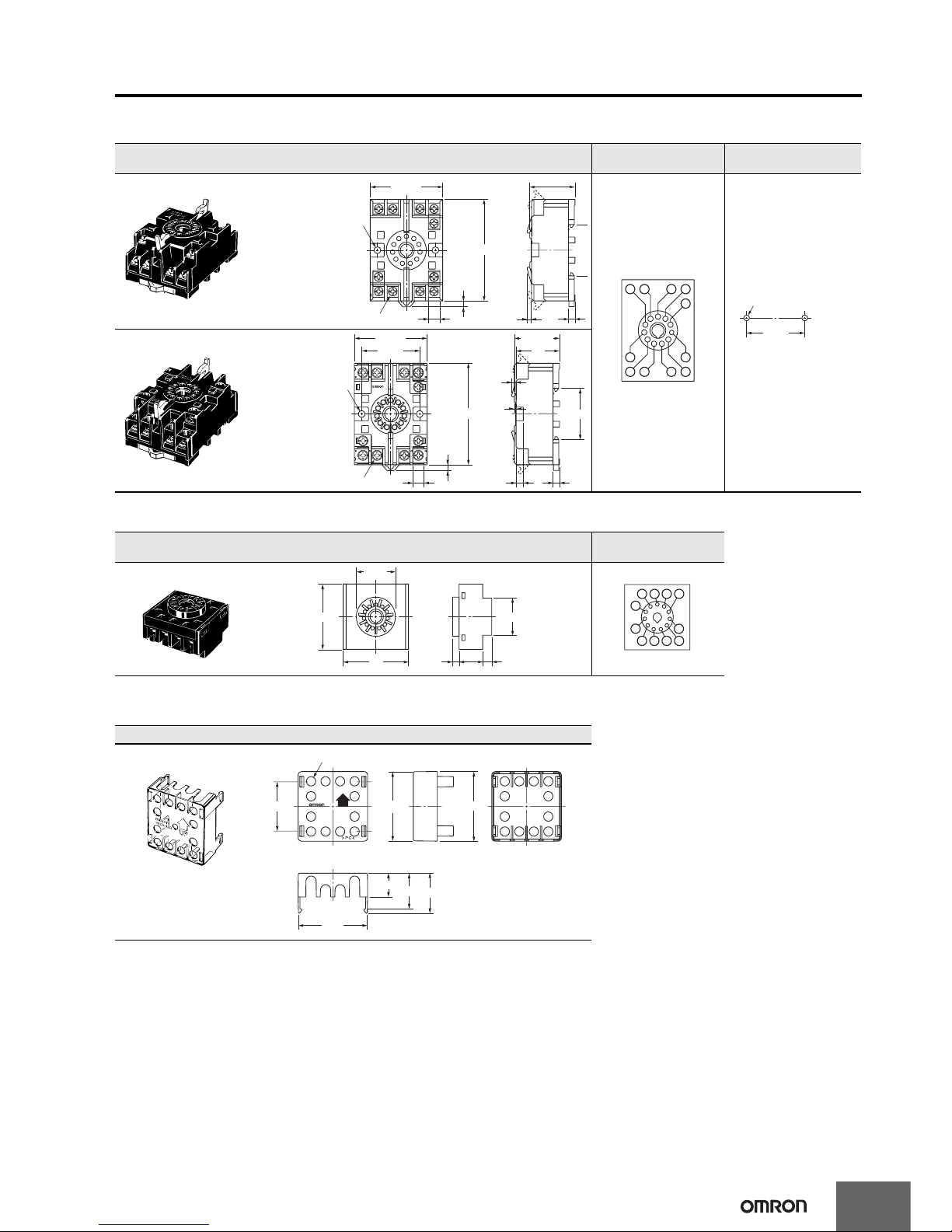
Connection Sockets
Front Connecting Socket
Note: Round crimp terminals cannot be used on Finger-safe Sockets. Use forked crimp terminals.
Back-connecting Sockets
Note: A Y92A-48G Terminal Cover can be used with the Socket to create a finger-safe construction.
Terminal Covers for P3GA-11 Back-connecting Socket
Note: The Terminal Cover can be used with a Back-mounting Socket (P3GA-11) to create a finger-safe construction.
Model Dimensions
Terminal arrangement
and internal connections
Mounting hole
dimensions
P2CF-11
(Top View)
Note: The Socket can
also be mounted
to DIN track.
P2CF-11-E
(Finger-safe Type)
Model Dimensions
Terminal arrangement
and internal connections
P3GA-11
(Bottom View)
Model Dimensions
Y92A-48G
4
70 max.
50 max.
Two, 4.5-dia. holes
Eleven, M3.5 × 7.5 sems screws
7.8
31.2 max.
4
3
8 7 6 5
10 11 1 2
9 3
4
40
±0.2
Two, M4 or 4.5-dia. holes
10 11
12
7865
3
4
9
P2CF-11-E
10A250VAC
RESISTIVE
4
40
±0.2
7.8
30
4.5
35.
4
1.2
3
5
70 max.
50 max.
Two, 4.5-dia. holes
Eleven, M3.5 × 7.5 set screws
31.2 max.
27 dia.
4.5
16.3
6.2
25.6
45
45
876
4
3
9
5
101112
Y92A-48G
UP
P C
34
Twelve, 6.4-dia. holes
47.7 × 47.7
48 × 48
27.6
24.6
16.5
47.4
Page 14

14
H7CX-A@-N
Optional Products for Track Mounting
Note: Order Spacers in increments of 10.
1
35
±0.3
7.3
±0.15
27
±0.15
4.5
15 25 2510
15 (5)*
1025 25
1,000 (500)*
* The values shown in parentheses
are for the PFP-50N.
Mounting Track
PFP-100N
PFP-50N
15 25 25
1,000
4.5
25 25 1510
1
242735
±
0.3
16
1.5
29.2
10
Mounting Track
PFP-100N2
4.8
1.3
35.5 35.3
1.8
1
1.8
10
6.2
M4 spring washer
50
11.5
10
M4 × 8
pan head
screw
End Plate
PFP-M
5
16
12
44.3
34.8
16.5
Spacer
PFP-S
Page 15
H7CX-A@-N
15
Counter
Operating Procedures
Setting Procedure Guide
Setting for Counter Operation
*
Use the following settings.
Setting for Tachometer Operation
*
Refer to page page 27.
* At the time of delivery, the H7CX is set to the 1-stage preset counter configuration. (2-stage models are set to the 2-stage preset counter configuration.) Refer to page page 35 fo r information
on switching models.
I/O Functions for Counter Operation
After making DIP switch settings for basic operations, advanced functions can be added using the operation keys.
For details, refer to page page 16.
Key-protect switch
Disabled Enabled
OFF
ON
OFF
ON
OFF
OFF
ON
ON
N
F
C
K-1
UP DOWN
Refer to the table on the right.
30 Hz 5 kHz
20 ms 1 ms
DIP switch settings
Counting speed
Input mode
Output mode
Minimum reset signal
Input selection
Output time 0.5 s 0.05 s
NPN PNP
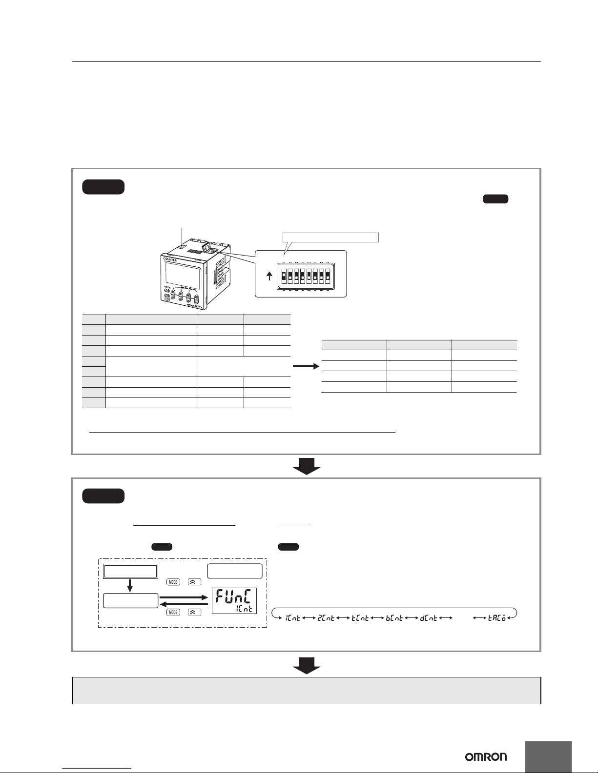
Note: All pins are factory-set to OFF.
• When setting functions using the DIP switch, be sure to set pin 1 of the DIP switch to ON.
• DIP switch settings are effective when the power is turned ON again. (Perform DIP switch settings while the power is OFF.)
Step1
Step3
Set the basic parameters.
(If the desired I/O mode is not listed below or to set all parameters using the front panel keys, perform ,
below.)
Note: can be performed first, followed by .
Note:
The configuration that can be selected depends on the model.
* The default mode is 1-stage preset counter configuration (2-stage preset counter configuration for 2-stage models).
Item OFF ON
Output modePin 5Pin 4
1
2
3
4
5
6
7
8
Step2
Step2 Step1
Hold down for 1 s min.
Select the function from Table 1 using the U (D) Key.
Run mode
Power ON
1
+
Hold down for 1 s min.
1
+
twn
The H7CX-A@-N is a Counter that contains more than one functional counter.
When using the Counter in any mode other than the default mode*, use the following chart to enter
Configuration Selection Mode and set the functions that are suitable to the application.
(1-stage
preset
counter)
(2-stage
preset
counter)
(Total and
preset counter)
(Batch
counter)
(Dual
counter)
(Twin
counter)
(Tachometer)
Configuration
selection mode
Be sure to set pin 1 to ON.
OFF
ON
12345678
Page 16
16
H7CX-A@-N
Counter
Run mode
Power ON
Function
setting mode
*3
*7
*5 Displayed for output modes other than K-2, D, L, and H only.
*5
*5
*6 Displayed only when the input mode is ud-a, ud-b, or ud-c.
(Not displayed when the function is set to twn.)
Note: Displayed only when the output mode is C, R, K-1, P, Q, A,
or K-2.
Note: Displayed for terminal-block models (except H7CX-A11@) only.
*3 When Using Dual Counter
Operation
*7 Set each digit using the individual U (D) Keys.
Note: Displayed only when the
output mode is C, R, K-1, P, Q,
A, or K-2.
Note: Displayed for output modes
other than D, L, and H.
HOLD cannot be set when
the output mode is K-2.
*7 Set each digit using the individual U (D) Keys.
Note: Displayed only when Twin Counter Mode is not selected.
(Red) (Green) (Orange)
(Red-green) (Green-red) (Red-orange) (Orange-red)
(Green-orange) (Orange-green)
3 s min.
*2
3 s min.
*1
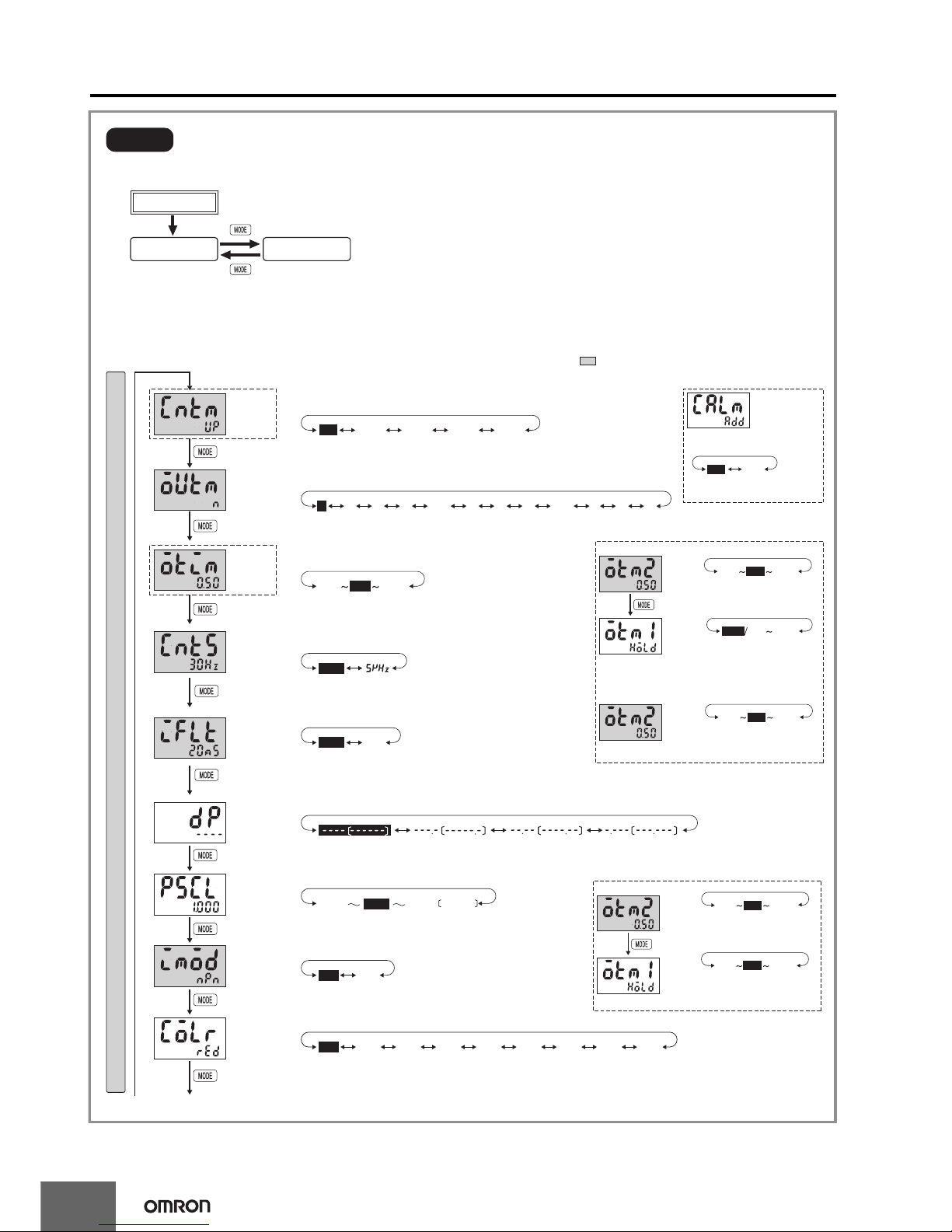
Step3
Parameters that cannot be set with the DIP switch are set with the operation keys on the front panel.
Change to Function Setting Mode.
Input mode
(CNTM)
Output
time
(OTIM)
Output mode
(OUTM)
NPN/PNP
input mode
(IMOD)
Display color
(COLR)
(1 ms)(20 ms)
(No decimal point)
Prescale
value
(PSCL)
Counting
speed
(CNTS)
(30 Hz) (5 kHz)
(PNP input)(NPN input)
The characters displayed in reverse video are the default settings.
When performing settings with operation keys only, set pin1 of the DIP switch to OFF (factory setting).
If pin 1 of the DIP switch is set to ON, the setting items indicated by will not be displayed.
For 6-digit models, only U Keys are provided.
Displays for 6-digit models are given in parentheses.
(N)
(0.50 s) (99.99 s)(0.01 s)
(0.01 s) (99.99 s)
(Outputs held)
(F) (C) (R) (K-1) (P) (Q) (A) (K-2) (D) (L) (H)
*6 *6 *6 *6
(DOWN) (
UP/DOWN A)(UP/DOWN B)(UP/DOWN C
)(UP)
(99.999)(1.000)(0.001)
(0.50 s) (99.99 s)(0.01 s)
To next pageFrom next page
(Addition) (Subtraction)
*4
Reset input
signal width
(IFLT)
Decimal
point position
(DP)
• Set the input mode using the U (D) Keys.
• Set the output mode using the U (D) Keys.
• Set each digit using the individual U (D) Keys.
• Set the counting speed using the U (D) Keys.
• Set the Reset input signal width using the U (D) Keys.
• Set the decimal point position using the U (D) Keys.
(One digit after
decimal point)
(Two digits after
decimal point)
(Three digits after
decimal point)
• Set each digit using the individual U (D) Keys.
(9.999)
• Set the NPN/PNP input mode using the U (D) Keys.
• Set the display color using the U (D) Keys.
Dual count
calculating
mode
(ADD)
• Set the dual count calculating
mode using the UD Keys.
*4 Displayed only when the output mode is K-2,
D, L, or H.
When using as a 2-stage preset counter
One-shot
output 2
time
(OTM2)
One-shot
output 1
time
(OTM1)
Note: Displayed only when the
output mode is C, R, K-1, P, Q,
A, or K-2.
(0.50 s) (99.99 s)(0.01 s)
When using as a batch counter
One-shot
output 2
time
(OTM2)
Function Setting Mode
grnred org r-g g-r r-o o-r g-o o-g
up
down
n
f
0.01 99.990.50
30hz
1ms
0.001
99.9999.999
1.000
pnpnpn
20ms
crk-1 k-2pqa dlh
subadd
0.50
hold 0.01 99.99
0.01 0.50 99.99
0.01 99.99
ud-a ud-b ud-c
*1 If the mode is switched to the function setting mode during operation, operation will continue.
*2 Changes made to settings in function setting mode are enabled for the first time when the mode is changed to run mode. Also,
when settings are changed, the counter is reset (present value initialized and output turned OFF) on returning to run mode.
If the output time is 0.00, hold is displayed.
Note: Displayed only when the
output mode is C, R, K-1, P,
Q, or A.
Note: Displayed only when the
output mode is C, R, K-1, P,
Q, or A.
(0.50 s) (99.99 s)(0.01 s)
Twin Counter
Output 2
output
time
(OTM2)
Output 1
output
time
(OTM1)
0.500.01 99.99
(0.50 s) (99.99 s)(0.01 s)
0.500.01 99.99
For details on operations and display in run mode, refer to page page 20.
The display depends on the selected configuration.
Page 17
H7CX-A@-N
17
Counter
(9999 × 1000 times)(0 × 1000 times)
(OFST)(ABS)
(KP-1) (KP-2) (KP-3) (KP-4) (KP-5) (KP-6) (KP-7)
(9999 × 1000 times)(0 × 1000 times)
(9999 × 1000 times)(0 × 1000 times)
99990
99990
99990
(9999)(1)
99991
(9999)(1)
99991
(9999)(1)
99991
ofstabs
kp-1 kp-2 kp-3 kp-4 kp-5
kp-6 kp-7
(ON)(OFF)
onoff
*8
Note: 1 to 999999 for 6-digit models
*8 Set each digit using the individual U (D) Keys.
Note: The monitor value is only displayed. It cannot be set.
Forecast
setting
upper limit
(PL-H)
Key protect
level
(KYPT)
From previous
page
To previous
page
Output ON
count alarm set
value/monitor
value
• Make the absolute value setting and forecast setting using the U (D) Keys.
• Set each digit using the individual U (D) Keys.
• Set each digit using the individual U (D) Keys.
• Set the key protect level using the U (D) Keys.
Procedure for Models Other than “-@W@” Models
Output
ON count
alarm set
value
Output
ON count
monitor
value
Output 1
(OUT1) ON
count alarm
set value
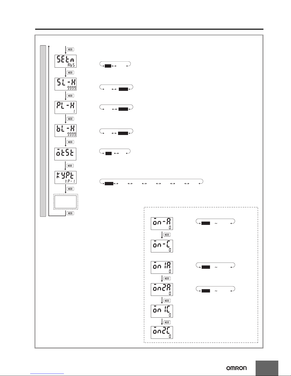
Function Setting Mode
Absolute value
setting/forecast
value setting
(SETM)
Set value
upper limit
(SL-H)
Note: 1 to 999999 for 6-digit models.
Note: 1 to 999999 for 6-digit models.
Note: Displayed only when the output mode is set to bcnt.
• Set each digit using the individual U (D) Keys.
Procedure for “-@W@” Models
Note: The monitor value is only displayed. It cannot be set.
Note: The monitor value is only displayed. It cannot be set.
Output 2
(OUT2) ON
count alarm
set value
Output 1
(OUT1) ON
count monitor
value
Output 2
(OUT2) ON
count monitor
value
Batch count
upper limit
(BL-H)
Note: Displayed only when the configuration selection mode is set to the 2-stage function 2cnt.
Note: Displayed only when the configuration selection mode is set to the 2-stage function 2cnt and a forecast value is set.
Output
allocation
change
Note: Displayed only for "-AU@" models.
off: Output 1 = 12, 13, Output 2 = 3, 4, 5 on: Output 1 = 3, 4, 5, Output 2 = 12, 13
The numbers are the terminals numbers.
Page 18

18
H7CX-A@-N
Counter
Explanation of Functions
Items marked with stars ★ can be set using the DIP switch.
Input Mode (cntm)★
Set increment mode (UP), decrement mode (DOWN), or one of the
increment/decrement modes (UP/DOWN A, UP/DOWN B, or UP/
DOWN C) as the input mode.
Input modes other than UP or DOWN modes cannot be set using the
DIP switch and so use the operation keys if other modes are required.
(For details on the operation of the input modes, refer to Input Modes
and Present Value on page page 21.)
Dual Count Calculating Mode ( calm)
When using as a dual counter, select either ADD (addition) or SUB
(subtraction) as the calculation method for the dual count value.
ADD: Dual count value = CP1 PV + CP2 PV
SUB: Dual count value = CP1 PV − CP2 PV
Output Mode (outm)★
Set the way that control output for the present value is output. The
possible settings are N, F, C, R, K-1, P, Q, A, K-2, D, L, and H.
Output modes other than N, F, C, or K-1 cannot be set using the DIP
switch and so use the operation keys if other modes are required. The
output modes that can be set vary with the model.
(For details on the operation of the output modes, refer to Input/
Output Mode Settings on page page 22.)
One-shot Output Time (otim)★
Set the one-shot output time (0.01 to 99.99 s) for control output.
One-shot output can be used only when C, R, K-1, P, Q, A, or K-2 is
selected as the output mode. Output times other than 0.5 s or 0.05 s
cannot be set with the DIP switch and so use the operation keys if
other settings are required.
One-shot Output 2 Time (otm2)★
Set the one-shot output time (0.01 to 99.99 s) for control output
(OUT2).
One-shot output can be used only when C, R, K-1, P, Q, A, or K-2 is
selected as the output mode. Output times other than 0.5 s or 0.05 s
cannot be set with the DIP switch and so use the operation keys if
other settings are required.
One-shot Output 1 Time (otm1)
Set the one-shot output time (0.01 to 99.99 s) for control output
(OUT1).
One-shot output can be used only when D, L, or H is selected as the
output mode.
If the output time is set to 0.00, hold is displayed, and outputs are
held.
Counting Speed (cnts)★
Set the maximum counting speed (30 Hz/5 kHz) for CP1 and CP2
inputs together.
If contacts are used for input signals, set the counting speed to 30 Hz.
Processing to eliminate chattering is performed for this setting.
Reset Input Signal Width (iflt)★
Set the reset input signal width (20 ms/1 ms) for reset/reset 1 and total
reset/reset 2 inputs together.
If contacts are used for the input signal, set the input signal width to
20 ms. Processing to eliminate chattering is performed for this setting.
Decimal Point Position (dp)
Decide the decimal point position for the present value, CP1/CP2
present values, set value (SV1, SV2), total count value, and dual
count set value.
Prescale Value (pscl)
Pulses input to the counter are converted according to the specified
prescale value.
(Setting range: 0.001 to 99.999 for 6-digit models and 0.001 to 9.999
for 4-digit models.)
Example: To display the feed distance for systems that output 25
pulses for a feed length of 0.5 m in the form @@.@@ m:
1. Set the decimal point position to 2 decimal places.
2. Set the prescale value to 0.02 (0.5 ÷ 25).
• Observe the following points when setting a prescale value.
Set the set value to a value less than {Maximum countable value
− Prescale value}.
Example: If the prescale value is 1.25 and the counting range is
0.000 to 999.999, set the set value to a value less than 998.749
(= 999.999 − 1.25).
If the set value is set to a value greater than this, output will not turn
ON.
• Output will turn ON, however, if a present value overflow occurs
(FFFFFF or FFFF).
NPN/PNP Input Mode (imod)
Select either NPN input (no-voltage input) or PNP input (voltage
input) as the input format. When using a two-wire sensor, select NPN
input.
The same setting is used for all external inputs.
For details on input connections, refer to Input Connections on page
page 9.
Display Color (colr) (Displayed for terminal block models
(except H7CX-A11@) only.)
Set the color used for the present value.
* Output 2 for 2-stage models.
With the twin counter, output 1 and output 2 will both turn OFF when
the output status is OFF. Either output 1 or output 2 will turn ON when
the output status is ON.
Output OFF* Output ON*
red
Red (fixed)
grn
Green (fixed)
org
Orange (fixed)
r-g
Red Green
g-r
Green Red
r-o
Red Orange
o-r
Orange Red
g-o
Green Orange
o-g
Orange Green
25 pulses
Encoder
0.5 m
Note: If the prescale value setting is incorrect, a counting error will
occur. Check that the settings are correct before using this
function.
Page 19

H7CX-A@-N
19
Counter
Absolute Value Setting/Forecast Value Setting (setm)
For the 2 count output mode, an absolute value setting (abs) or
forecast value setting (ofst) can be set for set value 1.
When a forecast value is set, specify the forecast value set value (i.e.,
the deviation for the set value).
The forecast output (output 1) turns ON when the present value
reaches the forecast value.
If the forecast set value is greater than or equal to the set value, the
forecast output (output 1) will turn ON as soon as counting starts.
If the forecast value setting is used, specify the set value 2 minus the
forecast value setting for set value 1.
Set Value Upper Limit (sl-h)
Set the upper limit for the set value when it is set in run mode.
The setting can be made from 1 to 9999 for 4-digit models and from
1 to 999999 for 6-digit models.
Forecast Set Upper Limit (pl-h)
Set the upper limit for the forecast set value.
The setting can be made from 1 to 9999 for 4-digit models and from
1 to 999999 for 6-digit models.
Batch Count Upper Limit (bl-h)
Set the upper limit for the batch count value. The setting can be made
from 1 to 9999 for 4-digit models and from 1 to 999999 for 6-digit
models.
Output Allocation (otst)
When using an H7CX-AU@-N model as a 2-stage counter, the output
can be flexibly allocated to either stage 1 or 2.
The transistor output can be allocated to SV1 and the contact output
to SV2 or vice verse, as in the following tables.
H7CX-AU-N/-AUD1-N
H7CX-AUSD1-N
Key Protect Level (kypt)
Set the key protect level.
Refer to Key Protect Level on page page 36.
Output ON Count Alarm Set Value (on-a)
Set the alarm value for the output ON count.
The limit can be set to between 0
× 1000 (0 times) and 9999 × 1000
(9,999,000 times). Only the underlined values are set. The alarm will
be disabled if 0 is set.
If the total ON count of the output exceeds the alarm set value, e3
will be displayed on the Timer to indicate that the output ON count
alarm value was exceeded. Refer to Self-diagnostic Function on page
page 36 for information on the e3 display.
ON Count Alarm Set Values for Outputs 1 and 2 (OUT1
and OUT2) (on1a and on2a)
Set the ON count alarm values for the outputs 1 and 2.
The limit can be set to between 0
× 1000 (0 times) and 9999 × 1000
(9,999,000 times). Only the underlined values are set. The alarm will
be disabled if 0 is set.
If the total ON count of instantaneous output 1 or 2 exceeds the alarm
set value, e3 will be displayed on the Timer to indicate that the output
ON count alarm value was exceeded. Refer to Self-diagnostic
Function on page page 36 for information on the e3 display.
Output ON Count Monitor Value (on-c)
The monitor value is only displayed. It cannot be set.
The output ON count will be 1,000 times the displayed value.
ON Count Monitor Values for Outputs 1 and 2 (OUT1 and
OUT2) (on1c and on2c)
The monitor value for output 1 or 2 is only displayed. It cannot be set.
The output ON count will be 1,000 times the displayed value.
Output 1 Output 2
off Transistor (12-13) Contact (3, 4, 5)
on Contact (3, 4, 5) Transistor (12-13)
Output 1 Output 2
off Transistor (12-13) Transistor with diode (3, 4, 5)
on Transistor with diode (3, 4, 5) Transistor (12-13)
Set value 2
Set value 1
0
Control output 1 (OUT1)
Control output 2 (OUT2)
Count value
Example: F Mode
Set value
Forecast
value
Forecast set value
0
Forecast output (OUT1)
Control output (OUT 2)
Count value
Example: F Mode
Page 20

20
H7CX-A@-N
Counter
Operation in Run Mode
I/O Functions for Counter Operation
Present value
Set value 1
Present value
Set value
Present value
Set value 2
Present value
Set value
Batch count value
Batch count set value
Present value 1
Set value 1
Present value 2
Set value 2
Present value
Set value
Total count value
Dual count value
Dual count
set value
CP1 present value
CP2 present value
Present value
Set value
Present value
Forecast Set Value
Total and Preset Counter
Batch Counter
Dual Counter
Twin Counter
• Set values for each digit as required using the U (D) Keys. (U Key only for 6-digit models.)
1-stage Preset Counter
2-stage Preset Counter with
Absolute Value Setting
• Present Value
Shows the present count value.
• Set Values (Set Value 1 and Set Value 2)
Set the set values.
When the present value reaches the set value (set
value 1 or set value 2), a signal is output according
to the specified output mode.
• Present Value/Set Value
Same as 1-stage preset counter.
• Total Count Value
Shows the present total count value.
• Present Value/Set Value
Same as 1-stage preset counter.
• Batch Count Value
Shows the number of times the count has been
completed for the present value.
• Batch Count Set Value
Set the batch count set value.
When the batch count value reaches the batch
count set value, batch output (OUT1) turns ON.
• Dual Count Value
Shows the sum of the CP1 present value and
CP2 present value when the dual count
calculating mode is ADD and shows the value
obtained by subtracting the CP2 present
value from the CP1 present value when the
dual count calculating mode is SUB.
• Dual Count Set Value
Set the dual count set value.
When the dual count value reaches the dual
count set value, signals are output according
to the specified output mode.
• CP1/CP2 Present Value
Show the present count values for CP1 and
CP2 present values respectively.
• Present Values 1 and 2
Shows the present count value 1 or 2.
• Set Values 1 and 2
Setting for present value 1 or 2.
• Present Value
Shows the present count value.
• Set Values
Set the set values.
• Forecast Set Value
Set the deviation for the set value.
2-stage Preset Counter with
Forecast Value Setting
Page 21

H7CX-A@-N
21
Counter
Input Modes and Present Value (See note 1.)
I/O Functions for Counter Operation
UP (Increment) Mode DOWN (Decrement) Mode
CP1: Count input; CP2: Prohibit (gate) input
must be greater than the minimum signal width. (See note 2.)
CP1: Count input; CP2: Prohibit (gate) input
must be greater than the minimum signal width. (See note 2.)
CP1: Prohibit (gate) input; CP2: Count input
must be greater than the minimum signal width. (See note 2.)
CP1: Prohibit (gate) input; CP2: Count input
must be greater than the minimum signal width. (See note 2.)
* Counting starts when the CP1 is turned ON after turning ON the power.
UP/DOWN A Command Input Mode UP/DOWN B Individual Input Mode
must be greater than the minimum signal width. (See note 2.)
UP/DOWN C Quadrature Input Mode
Note: 1. If the configuration selection is set to dual counter, CP1 and
CP2 input will operate in the same way as the count input
(CP1) of UP (increment) mode.
2. must be greater than the minimum signal width and
must be at least 1/2 the minimum signal width.
If they are less, a count error of ±1 may occur.
Minimum signal width: 16.7 ms (when maximum counting speed = 30 Hz)
100 µs (when maximum counting speed = 5 kHz)
3. The meaning of the H and L symbols in the tables is explained
below.
must be at least 1/2 the minimum signal width. (See note 2.)
0
CP1
H
L
CP2
Present value
H
L
0
1
2
4
3
5
Prohibit
A A
A
n
CP1
H
L
CP2
Present value
H
L
0
n−1
n−2
n−4
n−3
n−5
A A
Prohibit
A
0
*CP1
H
L
CP2
Present value
H
L
0
1
2
4
3
5
A A
Prohibit
A
n
*CP1
H
L
CP2
Present value
H
L
0
n−1
n−2
n−4
n−3
n−5
A A
Prohibit
A
0
CP1
H
L
CP2
Present value
H
L
0
1
2
2
2
1
3
3
A A
A
0
CP1
H
L
CP2
Present value
H
L
0
1
2
2
2
11
3
3
A
B
Symbol
Input method
No-voltage input
(NPN input)
Voltage input (PNP
input)
H Short-circuit 4.5 to 30 VDC
L Open 0 to 2 VDC
0
CP1
H
L
CP2
Present value
H
L
0
1
2
2
2
1
3
3
B B B B
B
Page 22

22
H7CX-A@-N
Counter
Input/Output Mode Settings
I/O Functions for Counter Operation
If a 1-stage model or 2-stage model is incorrectly used as twin counter, the operation for
output 2 will be performed. When using a 2-stage model as a 1-stage preset counter,
total and preset counter, or dual counter, OUT1 and OUT2 turn ON and OFF
simultaneously.
Input mode
Operation after count
completion
UP DOWN UP/DOWN A, B, C
Output
mode
setting
N
The outputs and present
value display are held
until reset/reset 1 is
input.
F
The present value
display continues to
increase/decrease.
The outputs are held until
reset/reset 1 is input.
C
As soon as the count
reaches SV, the present
value display returns to
the reset start status.
The present value display
does not show the
present value upon countup.
The outputs repeat oneshot operation.
OUT1 self-holding output
turns OFF after the OUT2
one-shot output time.
The OUT1 one-shot
output time is
independent of OUT2.
R
The present value
display returns to the
reset start status after
the one-shot output time.
The outputs repeat oneshot operation.
OUT1 self-holding output
turns OFF after the
OUT2 one-shot output
time.
The OUT1 one-shot
output time is
independent of OUT2.
K-1
The present value
display continues to
increase/decrease.
OUT1 self-holding output
turns OFF after the
OUT2 one-shot output
time.
The OUT1 one-shot
output time is
independent of OUT2.
Self-holding
output
Self-holding
output
One-shot output from OUT1
One-shot
output from OUT2
(The one-shot output time can be
set in the range 0.01 to 99.99s.)
Reset/
reset 1
OUT1
OUT2
999999
Set value 2
Set value 1
0
999999
0
Reset/
reset 1
OUT1
OUT2
Set value 2
Set value 1
999999
0
Reset/
reset 1
OUT1
OUT2
Set value 2
Set value 1
999999
0
Reset/
reset 1
OUT1
OUT2
Set value 2
Set value 1
999999
0
Reset/
reset 1
OUT1
OUT2
Set value 2
Set value 1
Page 23

H7CX-A@-N
23
Counter
Note: 1. The full scale (FS) for H7CX 4-digit models is 9999.
2. When the present value reaches 999999, it returns to 0.
3. Counting cannot be performed during reset/reset 1 input.
4. If reset/reset 1 is input while one-shot output is ON, one-shot output turns OFF.
5. If there is power failure while output is ON, output will turn ON again when the power supply has recovered.
For one-shot output, output will turn ON again for the duration of the output time setting once the power supply has recovered.
6. Do not use the counter function in applications where the count may be completed (again) while one-shot output is ON.
7. The setting range is 0 to 999,999 (0 to 9,999 for 4-digit models).
Self-holding
output
Self-holding
output
One-shot output from OUT1
One-shot
output from OUT2
(The one-shot output time c
a
set in the range 0.01 to 99.
9
Input mode
Operation after
count completion
UP DOWN UP/DOWN A, B, C
Output
mode
setting
P
The present value
display does not
change during the
one-shot output time
period, but the actual
count returns to the
reset start status.
The output will return
to one-shot mode.
The outputs repeat
one-shot operation.
OUT1 self-holding
output turns OFF after
the OUT2 one-shot
output time.
The OUT1 one-shot
output time is
independent of OUT2.
Q
The present value
continues to increase/
decrease for the oneshot output time, but
returns to the reset
start status after the
one-shot output time
has elapsed.
The outputs repeat
one-shot operation.
OUT1 self-holding
output turns OFF after
the OUT2 one-shot
output time.
The OUT1 one-shot
output time is
independent of OUT2.
A
The present value
display and OUT1
self-holding output is
held until reset/reset 1
is input.
OUT1 and OUT2 are
independent.
0
Reset/
reset 1
OUT1
OUT2
999999
Set value 2
Set value 1
0
Reset/
reset 1
OUT1
OUT2
999999
Set value 2
Set value 1
0
Reset/
reset 1
OUT1
OUT2
999999
Set value 2
Set value 1
Page 24

24
H7CX-A@-N
Counter
Note: 1. Counting cannot be performed during reset/reset 1 input.
2. If reset/reset 1 is input while one-shot output is ON, one-shot output turns OFF.
3. If there is power failure while output is ON, output will turn ON again when the power supply has recovered.
For one-shot output, output will turn ON again for the duration of the output time setting once the power supply has recovered.
4. Do not use the counter function in applications where the count may be completed (again) while one-shot output is ON.
5. The set value is from −99999 to 999999.
One-shot
output
Self-holding
output
Instantaneous
(equals) output
(The one-shot output time can be
set in the range 0.01 to 99.99s.)
Input mode
Operation after count completion
UP/DOWN A, B, C
Output
mode
setting
K-2
The display continues to increase/
decrease until the overflow or
underflow value is reached.
One-shot output only.
D
The display continues to increase/
decrease until the overflow or
underflow value is reached.
The outputs are ON while the count is
equal.
L
The display continues to increase/
decrease until the overflow or
underflow value is reached.
OUT1 is held while the present value
is less than or equal to set value 1.
OUT2 is held while the present value
is greater than or equal to set value 2.
H
The display continues to increase/
decrease until the overflow or
underflow value is reached.
OUT1 is held while the present value
is greater than or equal to set value 1.
OUT2 is held while the present value
is greater than or equal to set value 2.
* H mode is availa ble only when using a 6-
digit model as a 2-stage counter.
0
−99999
Reset/
reset 1
OUT1
OUT2
999999
Set value 2
Set value 1
0
−99999
Reset/
reset 1
OUT1
OUT2
999999
Set value 2
Set value 1
0
−99999
Reset/
reset 1
OUT1
OUT2
999999
Set value 2
Set value 1
0
−99999
Reset/
reset 1
OUT1
OUT2
999999
Set value 2
Set value 1
Page 25

H7CX-A@-N
25
Counter
Total and Preset Counter Operation
The H7CX has a total counter, separate from the 1-stage preset counter, for counting the total accumulated value.
Batch Counter Operation
The H7CX has a batch counter, separate from the 1-stage preset counter, for counting the number of times the count has been completed.
Note: 1. The batch count value is held at 0 during batch counter reset input.
2. If the batch count set value is 0, batch count will be performed but there will be no batch output.
3. The batch count value returns to 0 when it reaches 999,999 (9,999 for 4-digit models).
4. Once batch input has been turned ON, it will return to the ON state after power interruptions.
5. If the batch count set value is changed from a value that is greater than the batch count value to one that is less, batch output will turn ON.
6. After batch output turns ON, the ON state will be held even if the batch count set value is changed to a value greater than the batch count value.
Dual Counter Operation
Using the dual counter allows the count from 2 inputs to be added or subtracted and the result displayed. It is possible to specify a set value for
which output turns ON when the set value matches the added or subtracted result.
Note: 1. Counting is not possible for CP1 during reset 1 input. CP2 will not be affected. The dual count value will be calculated based on a CP1 present value of 0.
2. Counting is not possible for CP2 during reset 2 input. CP1 will not be affected. The dual count value will be calculated based on a CP2 present value of 0.
3. The counting range for the dual count value is −99,999 to 999,999 (0 to 9,999 for 4-digit models).
The counting ranges for the CP1 present value and CP2 present value are 0 to 999,999 (0 to 9,999 for 4-digit models).
If a present value exceeds 999,999 (9,999 for 4-digit models), FFFFFF (FFFF for 4-digit models) will be displayed to indicate an overflow, and all counting
will stop.
• The total counter continues to count the total
accumulated value when the present value is
reset using reset/reset 1 input (Reset Key).
• The total count value is reset when the total
reset/reset 2 input is turned ON.
If the Reset Key is pressed while the total count
value is displayed, the total count value is reset.
The present value is also reset at this time.
• The counting range of the total counter is
−99,999 to 999,999 (−999 to 9,999). The total
count value returns to 0 when it reaches the full
scale limit.
• The batch counter continues after count
completion.
• Batch output is held until batch counter reset is
input.
• When the batch counter reset input is turned
ON, the batch count value is reset, and batch
output turns OFF.
• If the Reset Key is pressed while the batch
count value is displayed, the batch count value
is reset and batch output turns OFF. The
present value is also reset at this time.
• The count value can be incremented and
decremented.
The batch count is only incremented.
• The maximum counting speed for batch counter
operation is 5 kHz. The batch counter counts
the number of times the count reaches the set
value.
• The operation after count completion for the
dual counter value is determined by the output
mode.
• The CP1 present value is reset when reset 1
input is turned ON.
The CP2 present value is reset when reset 2
input is turned ON.
• If the Reset Key is pressed while the dual count
value, CP1 present value, or CP2 present value
is displayed, all of the present values are reset
and outputs turn OFF. At this time, counting is
not possible for CP1 or CP2 inputs.
Reset/reset 1
Total Reset or Reset 2
0
Present value
Total count value
0
999999
Note: The full scale (FS) for H7CX 4-digit models is 9999.
0
Batch count set value
Sub-display
0
OUT1
(batch output)
Batch count value
(Main display)
1
2
Reset 1
Set value
OUT2
Present value
Note: The above is for when the output mode is C.
Reset 2 (batch
counter reset)
Reset 1 (CP1 reset)
Reset 2 (CP2 reset)
Dual count set value
Dual count value
0
CP1 present value
0
CP2 present value
0
OUT1, OUT2
Note: The above is for when the output mode is N.
0
0
0
Reset 1 (CP1 reset)
Reset 2 (CP2 reset)
Dual count set value
Dual count value
CP1 present value
CP2 present value
OUT1, OUT2
Note: The above is for when the output mode is K-2.
SUB mode can be used only when K-2, D, L,
or H is selected as the output mode with
6-digit models.
(1) Dual Count Calculating Mode = ADD
Dual count value = CP1 PV + CP2 PV
(2) Dual Count Calculating Mode = SUB
Dual count value = CP1 PV − CP2 PV
Page 26

26
H7CX-A@-N
Counter
Twin Counter Operation
Two independent counters are built in.
Note: 1. Only 2-stage models
2. Increment mode only for counters 1 and 2.
3. The settings for prescaling and the decimal point are used by both counter 1 and 2.
Reset Function List
I/O Functions for Counter Operation
• The following table shows the delay from when the present value passes the set value until the output is produced.
Actual measurements in N and K-2 modes (Reference values)
Note: The above times may vary slightly depending on the mode or operating conditions.
Counter 1 Counter 2
Counter input CP1 CP2
Reset input Reset 1 Reset 2
Present value display and
setting
Reset Key Only counters appearing on the display will be reset.
Function
1-stage/2-
stage preset
counter
Total and preset counter Batch counter Dual counter Twin counter
Screen displayed in run
mode
Present value/
set value (1, 2)
Present
value/set
value
Total count
value
Present
value/set
value
Batch count
value/batch
count set
value
Dual count
value/dual
count set
value
CP1 present
value/CP2
present
value
Present
value 1/Set
value 1
Present
value 2/Set
value 2
Reset/reset 1
Present value
and output
reset.
Present value and output
reset.
Present value and output
reset.
Only the CP1 present value is
reset.
Only the CP1 present value is
reset.
Total reset or
reset 2
No effect
Only the total count value is
reset.
Batch count value and batch
output reset.
Only the CP2 present value is
reset.
Only the CP2 present value is
reset.
Reset Key
Present value
and output
reset.
Present value
and output
reset.
Present
value, total
count value,
and output
reset.
Present value
and output
reset.
Present
value, batch
count value,
output and
batch output
reset.
CP1 present value, CP2
present value, dual count
value, and output reset.
CP1 present
value reset
CP2 present
value reset
Control output type Max. counting speed Output delay time
Contact output
30 Hz 16.5 to 24.0 ms
5 kHz 3.7 to 5.6 ms
Transistor output
30 Hz 12.0 to 20.0 ms
5 kHz 0.2 to 0.55 ms
Counter 1 present value
Counter 1 set value
Counter 2 present value
Counter 2 set value
Counter 1 display Counter 2 display
Switched with
the Key.
Page 27

H7CX-A@-N
27
Tachometer
Setting Procedure Guide
Tachometer Operation
After making DIP switch settings for basic operations, advanced functions can be added using the operation keys.
For details, refer to page page 28.
Step1
The H7CX is factory-set to the 2-stage counter configuration (1-stage counter configuration for
H7CX-AU@-N models).
Enter configuration selection mode using the following chart and set the tachometer mode.
OFF
ON
OFF
ON
OFF
OFF
ON
ON
Upper/lower limit output
Range output
Upper limit output
Lower limit output
OFF
ON
OFF
ON
OFF
OFF
ON
ON
OFF
2 times
4 times
8 times
--- ------
Step2
Key-protect switch
Disabled Enabled
Refer to the table on the right.
30 Hz 10 kHz
DIP switch settings
Counting speed
Tachometer output mode
Average processing
Input selection NPN PNP
Note: All pins are factory-set to OFF.
Step3
Set the basic parameters.
(If the desired I/O mode is not listed below or to set all parameters using the front panel keys, perform ,
below.)
Note: can be performed first, followed by .
Item OFF ON
Step2 Step1
Hold down for 1 s min.
Switch from 2cnt (2-stage preset counter mode) to taco (tachometer mode)
using the U Key.
Run mode
Power ON
1
+
Hold down for 1 s min.
1
+
Configuration
selection mode
Refer to the table on the right.
Tachometer output modePin 4Pin 3
Average processingPin 6Pin 5
1
2
3
4
5
6
7
8
• When setting functions using the DIP switch, be sure to set pin 1 of the DIP switch to ON.
• DIP switch settings are effective when the power is turned ON again. (Perform DIP switch settings while the power is OFF.)
Be sure to set pin 1 to ON.
OFF
ON
12345678
Page 28

28
H7CX-A@-N
Tachometer
Step3
(No decimal point) (One digit after
decimal point)
(Two digits after
decimal point)
(Three digits after
decimal point)
(Four digits after
decimal point)
(30 Hz) (10 kHz)
(99.9 s)(0.0 s)
(999.9 s)(0.1 s)
(99.999)(1.000)(0.001)
(No average
processing)
(Average of 2
measurements)
(Average of 4
measurements)
(Average of 8
measurements)
(Average of 16
measurements)
(Simple
averaging)
(Moving
average)
(LO)(HI)
(LO)(HI)
(AREA) (HI-HI) (LO-LO)(HI-LO)
hilo
30hz
--.----
0.001
smp mv
off
0.1 999.9
0.0 99.9
24816
1.000 99.999
area hihi lolo
(Error)
(Absolute ratio)
(1 input) (2 inputs)
f1 f2 f3 f4
(Error ratio)
f5
lohi
lohi
Run mode
Power ON
Function
setting mode
*1
*1 Set tachometer output modes 1 and 2 using the
U Key.
3 s min.
*2
3 s min.
*1
Parameters that cannot be set with the DIP switch are set with the operation keys on the front panel.
Change to Function Setting Mode.
Counting
speed
(CNTS)
Tachometer
output mode
(TOTM)
Auto-zero
time
(AUT00)
Startup time
(STMR)
Average
processing
(AVGN)
Decimal point
position
(DP)
The characters displayed in reverse video are the default settings.
When performing settings with operation keys only, set pin1 of the DIP switch to OFF (factory setting).
If pin 1 of the DIP switch is set to ON, the setting items indicated by will not be displayed.
To next pageFrom next page
Prescale
value
(PSCL)
Averaging
method
(AVGT)
• Set the tachometer input mode using the U Key.
Tachometer
output
mode 1
(TO1M)
* Displayed only when the tachometer input mode is F2
(2 inputs).
Function Setting Mode
*1 If the mode is switched to the function setting mode during operation, operation will continue.
*2 Changes made to settings in function setting mode are enabled for the first time when the mode is changed to run mode.
Also, when settings are changed, the counter is reset (measured value initialized and outputs turned OFF) on returning to run mode.
Tachometer
input mode
(TINM)
• Set the tachometer output mode using the U Key.
• Set the counting speed using the U Key.
• Set the decimal point position using the U Key.
• Set each digit using the individual U Key.
Note: “--.----“ will be displayed when pulse width measurement is set or when the display unit is set to seconds.
• Set the averaging method using the U Key.
• Set the number of averaging times using the U Key.
• Set each digit using the individual U Key.
• Set each digit using the individual U Key.
Tachometer
output
mode 2
(TO2M)
Note: Even if 10 kHz is selected when the tachometer input mode is F2 to F5, the counting speed will be 5 kHz.
For details on operations and display in run mode, refer to page page 33.
Page 29

H7CX-A@-N
29
Tachometer
(Enabled)(Disabled)
(Red) (Green) (Orange)
(Red-green) (Green-red)
(Red-orange) (Orange-red)
(Green-orange) (Orange-green)
(PNP input)(NPN input)
(19.99 s)(0.00 s)
99990
99990
(99999)(0)
999990
(999999)
999999
onoff
grnred org r-g g-r r-o o-r g-o o-g
npn pnp
19.990.00
(9999 × 1000 times)(0 × 1000 times)
(9999 × 1000 times)(0 × 1000 times)
*2 Set each digit using the individual U Keys.
From previous
page
To previous
page
• Set the NPN/PNP input mode using the U Key.
Output 1
(OUT1) ON
count alarm
set value
Output 2
(OUT2) ON
count alarm
set value
Output 1
(OUT1) ON
count monitor
value
Function Setting Mode
NPN/PNP
input mode
(IMOD)
Display
color
(COLR)
Note: The monitor value is only
displayed. It cannot be set.
Output 2
(OUT2) ON
count
monitor value
Peak/bottom
hold enabled
(DHLD)
Output
hysteresis
(HYS)
Output OFF
delay
(OFFD)
Set value
upper limit
(SL-H)
• Set the display color using the U Key.
• Enable or disable the peak/bottom hold using the U Key.
• Set the output hysteresis using the U Key.
Note: The measurement value after prescaling is set.
• Set each digit using the individual U Key.
• Set each digit using the individual U Key.
Note: The monitor value is only
displayed. It cannot be set.
(1)
1
(Pulse width
measurement)
(Pulse cycle
measurement)
(s)(Hz)
(Cont (10 ms min.))
(
200 ms)
(KP-1) (KP-2) (KP-3) (KP-4) (KP-5) (KP-6) (KP-7)
phas
shz
cont200ms
kp-1 kp-2 kp-3 kp-4 kp-5 kp-6 kp-7
*2
Key protect
level
(KYPT)
Pulse cycle
measurement/
pulse width
measurement
(CALM)
Display unit
(UNIT)
Measurement
interval
(INTV)
Output ON
count alarm set
value/monitor
value
• Set the key protect level using the U Key.
• Set pulse cycle measurement or pulse width measurement using the U Key.
• Set the display unit using the U Key.
Note: Displayed only when pulse cycle measurement is
used.
• Set each digit using the individual U Key.
Note: Displayed only if the measurement speed is 10 kHz
when pulse cycle measurement is used.
(ON)(OFF)
onoff
Output
allocation
change
Note: Displayed only for "-AU@" models.
off: Output 1 = 12, 13, Output 2 = 3, 4, 5
on: Output 1 = 3, 4, 5, Output 2 = 12, 13
The numbers are the terminals numbers.
Page 30

30
H7CX-A@-N
Tachometer
Explanation of Functions
Tachometer Operation
Items marked with stars ★ can be set using the DIP
switch.
Tachometer Input Mode (tinm)
Set the count input mode to one of the following: 1 input (F1), 2 inputs
(F2), error (F3), absolute ratio (F4), or error ratio (F5).
Tachometer Output Mode (totm)★
Set the output method for control output based on the comparison
value. Upper and lower limit (HI-LO), area (AREA), upper limit (HI-HI),
and lower limit (LO-LO) can be set.
(For details on the output modes, refer to Output Mode Settings and
Operation on page page 34.)
Counting Speed (cnts)★
Set the maximum counting speed (30 Hz/10 kHz) for CP1 input.
If contacts are used for input signals, set the counting speed to 30 Hz.
Processing to eliminate chattering is performed for this setting.
Decimal Point Position (dp)
Decide the decimal point position for the measurement value, OUT1
set value, and OUT2 set value.
Prescale Value (pscl)
It is possible to display the rate of rotation or the speed of a device or
machine to which the H7CX is mounted by converting input pulses to
a desired unit.
If this prescaling function is not used, the input frequency (Hz) will be
displayed.
It is also possible to specify time (seconds) as the display value. Refer
to Display Unit on page page 31 for details.
The relationship between display and input is determined by the
following equation. Set the prescale value according to the unit to be
displayed.
Displayed value = f × α
f: Input pulse frequency (number of pulses in 1 second)
α: Prescale value
(1) Displaying Rotation Rate
N: Number of pulses per revolution
Example: To display the rate of rotation for a machine that outputs 5
pulses per revolution in the form @@.@ rpm:
1. Set the decimal point position to 1 decimal places.
2. Using the formula, set the prescale value (α) to 1/N × 60 = 60/5 = 12.
(2) Displaying Speed
N: Number of pulses per revolution
d: Diameter of rotating body (m)
πd: Circumference (m)
• Observe the following points when
setting a prescale value.
Set the set value to a value less than {Maximum countable value −
Prescale value}.
Example: If the prescale value is 1.25 and the counting range is
0.000 to 999.999, set the set value to a value less than 998.749 (=
999.999 − 1.25).
If the set value is set to a value greater than this, output will not turn
ON.
* Output will turn ON, however, if a present value overflow occu rs (FFFFFF or FFFF}.
Averaging Method (avgt) (Only for Tachometer Operation)
A simple average or moving average can be selected for the
averaging. With the moving average method, the average of the
measurement values is displayed each sampling cycle, in contrast to
a simple average, with which the the average of the set number of
samples is displayed.
Number of Averaging Times (avgn)★
Flickering display and output chattering can be prevented using
average processing. Average processing can be set to one of four
levels: no average processing, 2 times (i.e., the average of 2
measurement values), 4 times, 8 times, or 16 times.
The measurement cycle will be equal to the sampling cycle multiplied
by the average processing setting (i.e., the number of times).
Average processing enables stable displays even for fluctuating input
signals. Set the optimum number of times for the application.
Auto-zero Time (auto0)
The display can be force-set to 0 if there is no pulse for a certain
period of time. This time is called the auto-zero time. Set the auto-zero
time to a time slightly longer than the estimated interval between input
pulses. Accurate measurement is not possible if the auto-zero time is
set to a time shorter than the input pulse cycle. Setting a time that is
too long may also result in problems, such as a time-lag between
rotation stopping and the alarm turning ON. The auto-zero time is not
applied to pulse width measurements.
Startup Time (stmr)
To prevent undesired outputs resulting from unstable inputs
immediately after the power supply is turned ON, it is possible to
prohibit measurement for a set period of time, the startup time.
It can also be used to stop measurements and disable outputs until
the rotating body reaches the normal rate of rotation, after the power
supply to the H7CX and rotating body are turned ON at the same time.
Input
mode
Input
Internal
processing
Application
1 input Count 1 None Operation with only one input.
2 inputs Counts 1 and 2 None
Operation with two
independent inputs.
Error Counts 1 and 2
Count 1 input −
Count 2 input
Measuring the difference
between two inputs (error in
number of revolutions).
Absolute
ratio
Counts 1 and 2
Count 1 input ÷
Count 2 input
Measuring the ratio of two
inputs (ratio of number of
revolutions).
Error ratio Counts 1 and 2
(Count 1 input −
Count 2 input) ÷
Count 2 input
Measuring the ratio of error
for two inputs (measuring the
error ratio of number of
revolutions).
Display unit Prescale value (α)
rpm 1/N × 60
rps 1/N
Display unit Prescale value (α)
m/min πd × 1/N × 60
m/s
πd × 1/N
d: Diameter
of rotating
body (m)
Note: If the prescale value setting is incorrect, a counting error will
occur. Check that the settings are correct before using this
function.
Startup timeDisplay
Time
Comparison value
(lower limit)
Output
(lower limit)
Power supply
Page 31

H7CX-A@-N
31
Tachometer
NPN/PNP Input Mode (imod)★
Select either NPN input (no-voltage input) or PNP input (voltage
input) as the input format.
When using a two-wire sensor, select NPN input. The same setting is
used for all external inputs.
For details on input connections, refer to Input Connections on page
page 9.
Display Color (colr)
Set the color used for the measurement value.
*1. If the tachometer output mode is set to AREA, however, the measured
value is displayed in red when control output 1 is OFF and in green when
control output 1 is ON.
*2. If the tachometer output mode is set to AREA, however, the measured
value is displayed in green when control output 1 is OFF and in red when
control output 1 is ON.
*3. If the tachometer output mode is set to AREA, however, the measured
value is displayed in red when control output 1 is OFF and in orange when
control output 1 is ON.
*4. If the tachometer output mode is set to AREA, however, the measured
value is displayed in orange when control output 1 is OFF and in red when
control output 1 is ON.
*5. If the tachometer output mode is set to AREA, however, the measured
value is displayed in green when control output 1 is OFF and in orange
when control output 1 is ON.
*6. If the tachometer output mode is set to AREA, however, the measured
value is displayed in orange when control output 1 is OFF and in green
when control output 1 is ON.
Peak/bottom Hold Enabled (dhld)
This function records the peak and bottom (i.e., minimum) after
counting starts (after turning ON the power supply or changing the
configuration selection mode or function setting). The peak value is
also held when the power supply is interrupted.
Output Hysteresis (hys)
This setting can be used to prevent output chattering if the
measurement value fluctuates slightly near the set value.
The measurement value after prescaling is set.
Output OFF Delay (offd)
This function delays the timing for turning OFF comparative output by
a certain time.
The ON time can be held for the set time if the comparative result
changes in a short time.
Operation will continue and outputs will not change when holding the
value.
Set Value Upper Limit (pl-h)
Set the upper limit for the set value when it is set in run mode. The
limit can be set to between 1 and 999999.
Output Allocation (otst)
When using an H7CX-AU@-N model as 2-stage counter, each output
can be flexibly allocated to either stage 1 or 2.
The transistor output can be allocated to SV1 and the contact output
to SV2 or vice verse, as in the following tables.
H7CX-AU-N/-AUD1-N
H7CX-AUSD1-N
Key Protect Level (kypt)
Set the key protect level.
Refer to Key Protect Level on page page 36.
Pulse Cycle Measurement/Pulse Width Measurement
(calm)
Set the measurement mode to pulse cycle measurement or pulse
width measurement.
With pulse cycle measurement, the number of pulse cycles that occur
in 1 s is measured.
With pulse width measurement, the ON time for one pulse is
measured.
An input OFF period of at least 20 ms is required for pulse width
measurement.
If there is no input pulse during pulse width measurement, the
previously measured value will be held.
Display Unit (unit)
When pulse cycle measurement is used, set the display unit to Hz
(hertz) or s (seconds).
Counting Interval (intv)
If the measurement speed is 10 kHz when pulse cycle measurement
is used, set the measurement interval to 200 ms or Cont (10 ms min.).
Control output OFF Control output ON
red
Red (fixed)
grn
Green (fixed)
org
Orange (fixed)
r-g *1
Measured value is
displayed in red when
both control outputs 1
and 2 are OFF.
Measured value is
displayed in green when
either control output 1 or
control output 2 is ON.
g-r *2
Measured value is
displayed in green when
both control outputs 1
and 2 are OFF.
Measured value is
displayed in red when
either control output 1 or
control output 2 is ON.
r-o *3
Measured value is
displayed in red when
both control outputs 1
and 2 are OFF.
Measured value is
displayed in orange
when both control
outputs 1 and 2 are
OFF.
o-r *4
Measured value is
displayed in orange
when both control
outputs 1 and 2 are
OFF.
Measured value is
displayed in red when
both control outputs 1
and 2 are OFF.
g-o *5
Measured value is
displayed in green when
both control outputs 1
and 2 are OFF.
Measured value is
displayed in orange
when both control
outputs 1 and 2 are
OFF.
o-g *6
Measured value is
displayed in orange
when both control
outputs 1 and 2 are
OFF.
Measured value is
displayed in green when
both control outputs 1
and 2 are OFF.
Output 1 Output 2
off Transistor (12-13) Contact (3, 4, 5)
on Contact (3, 4, 5) Transistor (12-13)
Output 1 Output 2
off Transistor (12-13) Transistor with diode (3, 4, 5)
on Transistor with diode (3, 4, 5) Transistor (12-13)
OUTX1
OUTY2
Display value
Comparison value 2
Hysteresis
Hysteresis
Comparison value 1
Set the hysteresis for when
the output turns OFF.
Page 32

32
H7CX-A@-N
Tachometer
ON Count Alarm Set Values for Outputs 1 and 2 (OUT1
and OUT2) (on1a and on2a)
Set the ON count alarm values for the outputs 1 and 2.
The limit can be set to between 0
× 1000 (0 times) and 9999 × 1000
(9,999,000 times). Only the underlined values are set. The alarm will
be disabled if 0 is set.
If the total ON count of instantaneous output 1 or 2 exceeds the alarm
set value, e3 will be displayed on the Timer to indicate that the output
ON count alarm value was exceeded. Refer to Self-diagnostic
Function on page page 36 for information on the e3 display.
ON Count Monitor Values for Outputs 1 and 2 (OUT1 and
OUT2) (on1c and on2c)
The monitor value for output 1 or 2 is only displayed. It cannot be set.
The output ON count will be 1,000 times the displayed value.
Page 33

H7CX-A@-N
33
Tachometer
Operation in Run Mode
Tachometer Operation
Bottom hold value
Peak hold value
Bottom hold value 1
Peak hold value 1
Bottom hold value 2
Peak hold value 2
Measurement value 1
Comparison value 1
Measurement value 2
Comparison value 2
Measurement value
• Set each digit using the individual U Keys.
Displayed when the input mode is not 2 inputs.
• Measurement value
Displays the currently measured value.
• Comparison value 1/Comparison value 2
Set comparison value 1 and comparison value 2.
The measurement value is compared to
comparison value 1 and comparison value 2 and
output is made according to the selected output
mode.
*3
*1 Measurement value 1 for the 2-input input mode.
*2 Measurement value 2 for the 2-input input mode.
*3 Peak/bottom hold enabled
Displayed for the 2-input input mode.
• Peak/bottom hold value
The peak (maximum) and bottom (minimum)
values are displayed after counting starts.
• Peak/bottom hold value 2
Peaks (maximums) 1 and 2 and bottoms
(minimums) 1 and 2 are displayed after counting
starts.
*1
*2
Note: The held values will be initialized when
the Reset Key (Hold Key) or reset 1 input
is turned OFF while peak/bottom hold
values 1 and 2 are being displayed. (The
reset 2 input operates in the same way if
the input mode is set to 2-input mode.)
Page 34

34
H7CX-A@-N
Output Mode Setting and Operation
Tachometer Operation
Input mode
setting
Output mode
setting
Operation
1 input
Error
Absolute ratio
Error ratio
Upper and
lower limit
(HI-LO)
Area (AREA)
Upper limit
(HI-HI)
Lower limit
(LO-LO)
2 inputs
Upper limit
(HI)
Lower limit
(LO)
OUT1
OUT2
Measurement value
(Upper-limit)
Comparison value 2
(Lower-limit)
Comparison value 1
ON condition for OUT1: Measurement value ≤ Comparison value 1
ON condition for OUT2: Measurement value ≥ Comparison value 2
OUT1
OUT2
Measurement value
Comparison value 2
Comparison value 1
Condition
Comparison value 1 ≤
Comparison value 2
Measurement value 1 >
Comparison value 2
ON condition
for OUT1
Comparison value 1 ≤
Measurement value ≤
Comparison value 2
Comparison value 2 ≤
Measurement value ≤
Comparison value 1
ON condition
for OUT2
Measurement value <
Comparison value 1 or
Measurement value >
Comparison value 2
Measurement value <
Comparison value 2 or
Measurement value >
Comparison value 1
OUT1
OUT2
Measurement value
(Upper-limit)
Comparison value 2
(Lower-limit)
Comparison value 1
ON condition for OUT1: Measurement value ≥ Comparison value 1
ON condition for OUT2: Measurement value ≥ Comparison value 2
OUT1
OUT2
Measurement value
(Upper-limit)
Comparison value 2
(Lower-limit)
Comparison value 1
ON condition for OUT1: Measurement value ≤ Comparison value 1
ON condition for OUT2: Measurement value ≤ Comparison value 2
OUT1
CP1 display value
Comparison value 1
Output 1
OUT2
CP2 display value
Comparison value 2
Output 2
ON condition for output 1: CP1 present value (display value) ≥ Comparison value 1
ON condition for output 2: CP2 present value (display value) ≥ Comparison value 2
OUT1
CP1 display value
Comparison value 1
Output 1
OUT2
CP2 display value
Comparison value 2
Output 2
ON condition for output 1: CP1 present value (display value) ≤ Comparison value 1
ON condition for output 2: CP2 present value (display value) ≤ Comparison value 2
Page 35

H7CX-A@-N
35
Switching between Preset Counter, Total and Preset Counter, Batch Counter, Dual
Counter, Twin Counter, and Tachometer Operation
Select which H7CX configuration is used (i.e., preset counter, total and preset counter, batch counter, dual counter, twin counter, or tachometer)
in configuration selection mode.
The H7CX is also equipped with a DIP switch monitor function, a convenient function that enables the settings of the DIP switch pins to be
confirmed using the display on the front of the H7CX.
Hold Function
The measurement value (display value) and output are sustained while the hold input is ON.
Note: The output will maintain the current status when the hold key is pressed.
Example:
Output mode
setting
Operation
Lower limit
1
+
1
1
RST
bcnt dcnt tacotwn1cnt 2cnt tcnt
Key
Key
Key
Key
…Indicates that DIP switch pin 8 is ON.
…Indicates that DIP switch pin 7 is OFF.
…Indicates that DIP switch pin 6 is ON.
…Indicates that DIP switch pin 5 is OFF.
…Indicates that DIP switch pin 4 is ON.
…Indicates that DIP switch pin 3 is OFF.
…Indicates that DIP switch pin 2 is ON.
…Indicates that DIP switch pin 1 is ON.
*The configurations that can be selected depend on the model.
Press the
key for 1 s
min.
*1 When the mode is changed to configuration selection mode, the present value is reset, outputs turn OFF, and counting (measuring) stops.
*2 Setting changes made in configuration selection mode are enabled when the mode is changed to run mode. If the configuration is changed, the
set value (or set value 1 and set value 2), comparison value 1 and comparison value 2 are initialized.
Power ON
Example
Configuration
selection
Note
DIP switch
monitor
(DIP)
Convenient
*2 *1
*This display is possible only when DIP switch pin 1 (DIP switch settings enable/disable)
is set to ON (enable).
Select the configuration using the UD Key.
Run mode
Configuration Selection Mode
1
1
To change the mode to configuration selection mode, hold
down the Key for 1 s min. with the Key held down.
The mode will not change if the Key is pressed first.
(1-stage
preset
counter)
(2-stage
preset
counter)
(Total and
preset counter)
(Batch
counter)
(Dual
counter)
(Twin
counter)
(Tachometer)
Note: By default, the H7CX is set to the 1-stage preset counter configuration. (Two-stage
models are set to the 2-stage preset counter configuration.)
Confirm the status of DIP switch pins 1 to 8 using the UD Key.
OFF
ON
12345678
OUT
Display value
Hold input* (Reset Key)
Comparison value (lower limit)
Sustained display value
Sustained output
Actual input
Page 36

36
H7CX-A@-N
Key Protect Level
It is possible to prevent setting errors by prohibiting the use of certain operation keys by specifying the key protect level (KP-1 to KP-7) when the
key-protect switch is set to ON.
The key protect level is set in the function setting mode. The key protect indicator is lit when the key-protect switch is ON.
* Changing mode to configuration selection mode or function setting mode.
Self-diagnostic Function
The following displays will appear if an error occurs.
*1. Displays for 4-digit models are given in parentheses.
*2. This includes times when the life of the EEPROM has expired.
*3. This occurs if the present value or total count value falls below −99999
(−999 for 4-digit models).
*4. This occurs in the following conditions if the present value (i.e.,
measurement value) exceeds 999999 (9999 for 4-digit models).
• For Output Modes K-2, D, L, or H
• Dual counter or tachometer operation is used.
*5. Display flashes.(1-second cycles)
*6. This does not apply when tachometer operation is used.
*7. This is displayed if the alarm value setting for either of the two outputs is
exceeded if a model with two outputs is used.The total ON count will not be
cleared by using the Reset Key.
*8. The normal display and e3 will appear alternately.
When the Reset Key is pressed, e3 will not be displayed even if the alarm
set value is exceeded.
(Monitoring is possible, however, because the counter will continue without
the output ON count being cleared.)
Level Description
Details
Changing modes*
Switching display
during operation
Reset Key Up/Down Keys
KP-1
(default setting)
Invalid Valid Valid Valid
KP-2 Invalid Valid Invalid Valid
KP-3 Invalid Valid Valid Invalid
KP-4 Invalid Valid Invalid Invalid
KP-5 Invalid Invalid Invalid Invalid
KP-6 Invalid Invalid Valid Valid
KP-7 Invalid Invalid Invalid Valid
*Factory-set to OFF
ON
(Enable)
OFF
(Disable)
*
Key protect indicator
Main display Sub-display Description Output status Correction method Set value after reset
----- (----)*1*5 No change Present value underflow*3 No change
Either press the Reset Key or turn
ON reset input.
No change
fffff (ffff)*1*5 No change Present value overflow*4 No change
Either press the Reset Key or turn
ON reset input.*6
No change
e1 Not lit CPU error OFF
Either press the Reset Key or
reset the power supply.
No change
e2 Not lit Memory error (RAM) OFF Turn ON the power again. No change
e2 sum Memory error (EEPROM)*2 OFF Reset Key Factory setting
e3*8 No change Output Counter Overflow No change Reset Key*7 No change
Page 37

H7CX-R@-N
37
• Tachometer-only model (DIN 48 × 48) for the H7CX
(Supports display and alarm outputs for numbers of rotations, speed, and
flow rate.)
• Socket design allows either flush or surface mounting.
• “-W” models added for control with two independent measurements.
• Operation in any of the four following modes is possible with the same Unit:
Upper and lower limit, upper limit, lower limit, and area.
• Equipped with auto-zero time, average processing, and startup time functions.
Specifications
Ratings
*1. Do not use the output from an inverter as the power supply. The ripple must be 20% maximum for CC power.
*2. The display is lit only when the power is ON. Nothing is displayed when power is OFF.
H7CX-R@-N Tachometer
Classification Tachometer
Item Model H7CX-R11@-N H7CX-R11W@-N
Input mode 1 input only 2 inputs only
Ratings
Power supply
voltage
*1
• 100 to 240 VAC, 50/60 Hz
• 12 to 24 VDC or 24 VAC, 50/60 Hz
Operating voltage fluctuation
range
85% to 110% of rated supply voltage (90% to 110% at 12 to 24 VDC)
Power consumption
Approx. 9.4 VA at 100 to 240 VAC, Approx. 7.2 VA/4.7 W at 24 VAC/12 to 24 VDC, Approx. 3.7 W at 12 to 24 VDC
Mounting method Flush mounting or surface mounting
External connections 11-pin socket
Degree of protection IEC IP66, UL508 Type 4 (indoors) for panel surface only and when Y92S-29 Waterproof Packing is used
Input signals Count and hold Count 1 and count 2
Pulse measurement method Tachometer mode (cycle measurement)
AMD-compatible mode (continuous
measurement)
Tachometer mode (cycle measurement)
Maximum counting speed 30 Hz 10 kHz --- 5 kHz
Minimum input signal width --- 10 ms 1 ms --Measuring ranges 0.01 Hz to 30.00Hz
0.01 Hz to 10 kHz
0.026 to 999999 s 0.003 to 999999 s 0.01 to 5k Hz
Sampling cycle 200 ms min.
Continuous measurement (minimum
interval of 10 ms)
200 ms min.
Display refresh cycle
• Input pulse of 5 Hz min.
Averaging not used: 200 ms
Averaging used: 200 multiplied by the averaging setting (ms)
• Input pulse of less than 5 Hz
Using averaging: Two times the maximum input pulse cycle
Using averaging: Two times the maximum of the input pulse cycle multiplied by the averaging setting.
Measuring accuracy ±0.1% FS ±1 digit max. (at 23 ±5°C)
Output mode HI-LO, AREA, HI-HI, LO-LO HI-HI, LO-LO
Auto-zero time 0.1 to 999.9 s (in Tachometer Mode)
Startup time 0.0 to 99.9 s
Averaging Simple averaging/moving averaging selectable, Number of times: OFF, 2, 4, or 8 times
Prescaling function 0.001 to 99.999 (in Tachometer Mode)
Decimal point adjustment Rightmost 3 digits ---
Sensor waiting time 290 ms max. (Control output is turned OFF and no input is accepted during sensor waiting time.)
Input
Input method
No-voltage Input
Impedance when ON: 1 kΩ max.
(Leakage current: 12 mA when 0 Ω)
ON residual voltage: 3 V max.
Impedance when OFF: 100 kΩ min.
Voltage Input
High (logic) level: 4.5 to 30 VDC
Low (logic) level: 0 to 2 VDC
(Input resistance: approx. 4.7 kΩ)
No-voltage input/voltage input (switchable)
Hold input Minimum input signal width: 20 ms ---
External power supply
12 VDC (±10%), 100 mA
* Refer to Safety Precautions (Common) on page page 52 for details.
Control output
Contact output: 3 A at 250 VAC/30 VDC, resistive load (cosφ=1)
Minimum applied load:10 mA at 5 VDC (failure level: P, reference value)
Display*2
7-segment, negative transmissive LCD
Character height
Present value: 10 mm (red), comparison value: 6 mm (green)
Digits 6 digits (0 to 999999)
Memory backup EEPROM (overwrites: 100,000 times min.) that can store data for 10 years min.
Operating temperature range −10 to 55°C (−10 to 50°C if Counter/Tachometers are mounted side by side) (with no icing or condensation)
Storage temperature range −25 to 70°C (with no icing or condensation)
Operating humidity range 25% to 85%
Case color Black (N1.5)
Page 38

38
H7CX-R@-N
Characteristics
I/O Functions
* Refer to pa ge page 50 for details on the hol d function.
• The following table shows the delay from when the reset signal is
input until the output is turned OFF. (Reference values)
*See Life-test Curve (Reference Values) on the right.
Applicable Standards
* The following safety standards apply to the H7CX-R11@.
cUL (Listing): Applicable when an OMRON P2CF(-E) Socket is used.
cUR (Recognition): Applicable when any other socket is used.
Insulation resistance
100 MΩ min. (at 500 VDC) between current-carrying terminal and exposed noncurrent-carrying metal parts, and between non-continuous contacts
Dielectric strength
2,000 VAC, 50/60 Hz for 1 min between current-carrying metal parts and non-currentcarrying metal parts
2,000 VAC (for 100 to 240 VAC), 50/60 Hz for 1 min between power supply and input
circuit (1,000 VAC for 24 VAC/12 to 24 VDC)
2,000 VAC 50/60 Hz for 1 min between control output, power supply, and input circuit
1,000 VAC, 50/60 Hz for 1 min between non-continuous contacts
Impulse withstand voltage
3.0 kV (between power terminals) for 100 to 240 VAC, 1.0 kV for 24 VAC/12 to 24 VDC
4.5 kV (between current-carrying terminal and exposed non-current-carrying metal
parts) for 100 to 240 VAC, 1.5 kV for 24 VAC/12 to 24 VDC
Noise immunity
±1.5 kV (between power terminals)
±600 V (between input terminals)
Square-wave noise by noise simulator (pulse width: 100 ns/1 µs, 1-ns rise)
Static immunity Destruction: 15 kV, Malfunction: 8 kV
Vibration
resistance
Destruction 10 to 55 Hz with 0.75-mm single amplitude, each in three directions for 2 hours
Malfunction 10 to 55 Hz with 0.35-mm single amplitude, each in three directions for 10 min
Shock resistance
Destruction 300m/s2 each in three directions, three cycles
Malfunction 100m/s2 each in three directions, three cycles
Life expectancy
Mechanical: 10,000,000 operations min.
Electrical: 100,000 operations min. (3 A at 250 VAC, resistive load, ambient
temperature condition: 23°C) *
Weight Approx. 110 g (Tachometer only)
Approved
safety
standards
cULus (or cURus): UL508/CSA C22.2 No. 14*
Conforms to EN 61010-1 (IEC 61010-1): Pollution degree 2/overvoltage category II, B300 PILOT DUTY,
1/4 HP 120 VAC, 1/3 HP, 240 VAC, 3-A resistive load
EMC
(EMI)
Emission Enclosure:
Emission AC mains:
(EMS)
Immunity ESD:
Immunity RF-interference:
Immunity Conducted Disturbance:
Immunity Burst:
Immunity Surge:
Immunity Voltage Dip/Interruption:
EN61326
EN55011 Group 1 classA
EN55011 Group 1 classA
EN61326
EN61000-4-2: 4 kV contact discharge (level 2);
8 kV air discharge (level 3)
EN61000-4-3: 10 V/m (Amplitude-modulated, 80 MHz to 1 GHz)
(level 3);
10 V/m (Pulse-modulated, 900 MHz ±5 MHz) (level 3)
EN61000-4-6: 10 V (0.15 to 80 MHz) (level 3)
EN61000-4-4: 2 kV power-line (level 3);
1 kV I/O signal-line (level 4)
EN61000-4-5: 1 kV line to lines (power and output lines) (level 2);
2 kV line to ground (power and output lines) (level 3)
EN61000-4-11: 0.5 cycle, 100% (rated voltage)
Life-test Curve
(Reference Values)
Resistive Load
Inductive Load
A current of 0.15 A max. can be switched at
125 VDC (cosφ=1) (Life expectancy: 100,000
operations)
A current of 0.1 A max. can be switched if
L/R=7 ms.
(Life expectancy: 100,000 op erations)
1,000
700
500
300
100
70
50
Load current (A)
01 2 34
30 VDC (cosφ=1)
250 VAC (cosφ=1)
No. of operations (
×
10
3
)
1,000
700
500
300
100
70
50
01 2 34
30 VDC (L/R=7 ms)
Load current (A)
250 VAC (cosφ=1)
No. of operations (
×
10
3
)
Inputs
Count,
count 1,
count 2
Reads counting signals.
Hold
• Holds the measurement value and outputs.
• The hold indicator is lit during hold.*
Outputs OUT
Outputs signals according to the specified output
mode when a comparison value is reached.
Minimum reset signal width Output delay time
1 ms 0.8 to 1.2 ms
20 ms 15 to 25 ms
Page 39

H7CX-R@-N
39
Connections
Terminal Arrangement
* The hold function is the same whichever terminal is connected. Terminals are not
connected internally, and so do not use them for cross-over wiring.
Transistor Output
• The transistor output of the H7CX is isolated from the internal
circuitry by a photocoupler, so the transistor output can be used as
both NPN and PNP output.
• The diode connected to the collector of the output transistor is used
to absorb inverted voltage that is generated when an inductive load
is connected to the H7CX.
Block Diagram
Input Circuits
Count and Hold Inputs
6
7
8
9
10
11
1
2
3
4
5
OUT
0 V
(+)
(−)
(−)
(+)
Sensor
12 VDC
External
power supply
Internal circui
t
Count
Hold
Hold
Hold
*
*
*
H7CX-R11-N
H7CX-R11D1-N
6
7
8
9
10
11
1
2
3
4
5
OUT1
OUT2
0 V
(+)
(−)
(−)
(+)
Sensor
12 VDC
External
power supply
Internal circui
t
Internal circuit
Count 1
Count 2
H7CX-R11W-N
H7CX-R11WD1-N
Power for load
+
Load
Power for load
+
Load
NPN Output PNP Output
Power for load
+
Counter
Inductive
load
No-voltage Inputs
(NPN Inputs)
Voltage Inputs
(PNP Inputs)
Output circuit
Display circuit
Input circuits
(Basic insulation)
(Basic insulation)
(Basic insulation)
Internal
control circuit
Power supply
circuit
Key switch
circuit
Internal
circuit
IN
+14V
1 kΩ
IN
Approx. 4.7 kΩ
Internal
circuit
Page 40

40
H7CX-R@-N
Input Connections
The inputs of the H7CX-R are no-voltage (short-circuit or open) inputs or voltage inputs. They are set for use as voltage inputs at the time of
delivery.
No-voltage Inputs (NPN Inputs)
No-voltage Input Signal Levels
Note: The DC voltage must be 30 VDC max.
Voltage Inputs (PNP Inputs)
Voltage Input Signal Levels
Open Collector Voltage Output Contact Input DC Two-wire Sensor
H7CX-R11@
3547 6
PLC or
sensor
0 V for inputs
Hold
Count
Note: Operates when the transistor turns ON.
H7CX-R11W@
3 --- 6
Sensor,
etc.
0 V for inputs
Hold
Count
Note: Operates when the transistor turns ON.
H7CX-R11@
3547 6
H7CX-R11W@
3 --- 6
0 V for inputs
Hold
Count
Note: Operate when the contact turns ON.
H7CX-R11@
3547 6
H7CX-R11W@
3 --- 6
0 V for inputs
Hold
Count
Note: Operates when the transistor turns ON.
H7CX-R11@
3547 6
H7CX-R11W@
3 --- 6
No-contact
input
Short-circuit level (Transistor ON)
• Residual voltage: 3 V max.
• Impedance when ON: 1 kΩ max.
(The leakage current is approx. 12 mA when the impedance is 0 Ω.)
Open level (Transistor OFF)
• Impedance when OFF: 100 kΩ min.
Contact input
Use contacts which can adequately switch 5 mA at 10 V.
Applicable Two-wire Sensor
• Leakage current: 1.5 mA max.
• Switching capacity: 5 mA min.
• Residual voltage: 3 VDC max.
• Operating voltage: 10 VDC
No-contact Input (NPN Transistor) No-contact Input (PNP Transistor) Contact Input
Sensor,
etc.
0 V for inputs
Hold
Count
Note: Operate when the transistor turns OFF.
H7CX-R11@
3547 6
H7CX-R11W@
3 --- 6
Sensor,
etc.
0 V for inputs
Hold
Count
Note: Operate when the transistor turns ON.
H7CX-R11@
3547 6
H7CX-R11W@
3 --- 6
0 V for inputs
Hold
Count
Note: Operate when the contact turns ON.
H7CX-R11@
3547 6
H7CX-R11W@
3 --- 6
High level (Input ON): 4.5 to 30 VDC
Note: 1. The DC voltage must be 30 VDC max.
2. Input resistance: Approx. 4.7 kΩ
Low level (Input OFF): 0 to 2 VDC
Page 41

H7CX-R@-N
41
Nomenclature
Dimensions (Unit: mm)
Tachometers
(Factory setting)
ON
(Enable)
(Factory setting) OFF
(Disable)
10 mm
6 mm
6
4
5
7
8
9
10
11
2
3
1
1. Hold Indicator (orange)
2. Key Protect Indicator (orange)
3. Control Output Indicator (orange)
4. Comparison Value 1, 2 Stage Indicator
(1-output models)
(2-output models)
Lit when the key protect switch is ON.
(Lit when the hold input or hold key is ON. )
7. Mode Key
(Used to switch mode and setting items.)
11. DIP Switch
1 6
5. Present Value (Main Display)
8. Hold Key
9. Up Keys to
Character height: 10 mm (red)
(Used to sustain the measurement value and output.)
6. Comparison Value (Sub-display)
Character height: 6 mm (green)
10. Key-protect Switch
1st digit
6th digit
Display Section
Operation Keys
Switches
Character Size
for Sub-display
Character Size
for Main Display
OFF
ON
12345678
OUT
OUT
1 2
63.7
14.4
6
44.8 × 44.8
48 × 48
Dimensions without Flush Mounting Adapter
H7CX-R@-N
Note: 1. The mounting panel thickness should be 1 to 5 mm.
2. To allow easier operation, it is recommended that
Adapters be mounted so that the gap between
sides with hooks is at least 15 mm (i.e., with the
panel cutouts separated by at least 60 mm).
3. It is possible to mount counters side by side, but
only in the direction without the hooks. If Counters/
Tachometers are mounted side by side, however,
water resistance will be lost.
60 min.
60 min.
15 min.
45
+0.6
−0
45
+0.6
−0
n side by side mounting
A
With Y92A-48F1 attached.
With Y92A-48 attached.
A=(48n−2.5)
+1
−0
A=(51n−5.5)
+1
−0
A={48n−2.5+(n−1)×4}
+1
−0
Panel Cutouts
Panel cutouts are as shown below
(according to DIN43700).
58
48
89.97.5
Panel
(51)
Y92S-29 (order separately)
Waterproof Packing
Y92F-30 (order separately)
Flush Mounting Adapter
P3GA-11
(order
separately)
Rear Surface
Connection
Socket
Dimensions with Flush Mounting Adapter (Adapter and
Waterproof Packing Ordered Separately)
H7CX-R@-N
H7CX-R@-N
P2CF-11(-E) (order separately)
Front Connecting Socket
100.9
103.2*
Dimensions with Front Connecting Socket
H7CX-R@-N
* These dimensions vary with the kind of DIN track (reference value).
Page 42

42
H7CX-R@-N
Accessories (Order Separately)
Soft Cover
Y92A-48F1
Protecting the Timer in Environments Subject to Oil
Hard Cover
Y92A-48
Order the Waterproof Packing separately if it is lost or damaged.
The Waterproof Packing can be used to achieve protection equivalent
to IP66.
(The Waterproof Packing will deteriorate, harden, and shrink
depending on the application environment. To ensure maintaining the
NEMA4 waterproof level, periodically replace the Waterproof
Packing. The periodic replacement period will depend on the
application environment. You must confirm the proper replacement
period. Use 1 year or less as a guideline. If the Waterproof Packing is
not replaced periodically, the waterproof level will not be maintained.)
It is not necessary to mount the Waterproof Packing if waterproof
construction is not required.
Connection Sockets
Refer to Connection Sockets on page page 13 for details.
Optional Products for Track Mounting
Refer to Optional Products for Track Mounting on page page 14 for details.
The H7CX's panel surface is water-resistive (conforming to IP@6,
UL Type 4X) and so even if drops of water penetrate the gaps
between the keys, there will be no adverse effect on internal circuits.
If, however, there is a possibility of oil being present on the
operator's hands, use the Soft Cover. The Soft Cover ensures
protection equivalent to IP54 against oil. Do not, however, use the
H7CX in locations where it would come in direct contact with oil.
Note: Depending on the operating environment, the condition
of resin or rubber products may deteriorate, or they may
shrink or become harder. Therefore, it is recommended
that resin products be replaced regularly.
Y92F-45
Use this Adapter to install the
Counter/Tachometer in a cutout
previously made for a DIN 72 × 72 mm
device (panel cutout: 68 × 68 mm).
Flush Mounting
Adapter
Y92F-30
Order a Flush Mounting Adapter
separately if the product is to be
flush-mounted.
Waterproof Packing
Y92S-29
Page 43

H7CX-R@-N
43
Operating Procedures
Parameters must be set using both the DIP switch and the operation keys on the front panel.
Refer to the following for the detailed procedure.
The settings made using the DIP switch can be checked in the
DIP switch monitor mode.
OFF
ON
OFF
ON
OFF
OFF
ON
ON
Tachometer
AMD compatible
Tachometer
AMD compatible
Input mode
*1
Counting speed/
Minimum input signal width
Output mode
*2
Average processing
---
NPN/PNP input mode
--- ---
NPN PNP
30 Hz
10 ms
10 kHz
*3
1 ms
OFF
ON
OFF
ON
OFF
OFF
ON
ON
Upper and lower limit
Area
Upper limit
Lower limit
OFF
ON
OFF
ON
OFF
OFF
ON
ON
OFF (no average processing)
2 times
4 times
8 times
Step1
Upper limit
Upper limit
Item OFF ON
Counting speed/
minimum input signal width
Input modePin 2Pin 1
Output modePin 4Pin 6
Average processingPin 6Pin 5
1
2
3
4
5
6
7
8
Set the basic parameters.
Refer to the table on the right.
Note: The characters displayed in reverse video are the default settings.
Refer to the table on the right.
Refer to the table on the right.
*1. The setting is disabled (OFF) for the H7CX-R11W@.
*2. For the H7CX-R11W@.
Refer to the table on the right.
Refer to the table on the right.
Output mode
Output mode
Note: The characters displayed in reverse video are the default settings.
OFF
ON
OFF
ON
3
4
Item OFF ON
Output modePin 4
Output mode
Pin 3
Lower limit
Lower limit
*3. For the H7CX-R11W@, the counting speed will be 5 kHz even if 10 kHz
is selected.
OFF
ON
12345678
(Factory setting)
Page 44

44
H7CX-R@-N
(99.9 s)(0.0 s)
(Enabled)(Disabled)
(99999)(0)
(19.99 s)(0.00 s)
(999999)(1)
(999.9 s)(0.1 s)
kp-1
off on
0 99999
0.00 19.99
9999991
kp-2 kp-3 kp-4 kp-5 kp-6 kp-7
0 9999
0 9999
0 9999
Procedure for Models Other than “-R11W@” Models
Procedure for “-R11W@” Models
(9999 × 1000 times)(0 × 1000 times)
(KP-1) (KP-2) (KP-3) (KP-4) (KP-5) (KP-6) (KP-7)
*1
Note: Not displayed in AMD-compatible mode.
*1 Set each digit using the individual U Key.
Note: The monitor value is only
displayed. It cannot be set.
Output OFF
delay
(OFFD)
Output ON
count alarm set
value/monitor
value
• Set each digit using the individual U Key.
Function Setting Mode
Auto-zero
time
(AUTO0)
Startup
time
(STMR)
Peak/bottom
hold
enabled
(DHLD)
Output
hysteresis
(HYS)
Set value
upper limit
(SL-H)
Key
protect
level
(KYPT)
• Set each digit using the individual U Key.
• Enable or disable peak/bottom hold using the U Key.
• Set the output hysteresis using the U Key.
• Set each digit using the individual U Key.
Note: The measurement value after prescaling is set.
• Set each digit using the individual U Key.
• Set the key protect level using the U Key.
Output
ON count
alarm set
value
Output
ON count
monitor
value
Output 1
(OUT1) ON
count alarm
set value
Output 2
(OUT2) ON
count alarm
set value
Note: The monitor value is only
displayed. It cannot be set.
Note: The monitor value is only
displayed. It cannot be set.
Output 1
(OUT1) ON
count
monitor
value
Output 2
(OUT2) ON
count
monitor
value
(9999 × 1000 times)(0 × 1000 times)
(9999 × 1000 times)(0 × 1000 times)
(MV)(SMP)
(99.999)(1.000)(0.001)
The characters displayed in reverse video are the default settings.
smp mv
Power ON
Run mode
Step2
Change to Function Setting Mode.
3 s min.
*2
3 s min.
*1
• Set the decimal point position using the U Key.
*1 If the mode is switched to the function setting mode during operation, operation will
continue.
*2 Changes made to settings in function setting mode are enabled for the first time when the
mode is changed to run mode.
Also, when settings are changed, the counter is reset (measured values initialized and
output turned OFF) on returning to run mode.
Function
setting mode
Averaging
method
(AUGT)
Prescale value
(PSCL)
Decimal point
position
(DP)
(No decimal point)
(One digit after
decimal point)
(Two digits after
decimal point)
(Three digits after
decimal point)
• Set each digit using the individual U Key.
• Set the averaging method using the U Key.
Note: Not displayed in AMD-compatible mode.
For details on operations in run mode, refer to page page 47.
Page 45

H7CX-R@-N
45
Explanation of Functions
Basic Functions
Input Mode
The mode can be switched between tachometer mode and AMDcompatible mode.
Tachometer Mode
Use this mode to measure the pulse frequency (Hz).
AMD-compatible Mode
Use this mode to measure the pulse cycle (s).
Counting Speed
Set the maximum counting speed (30 Hz/10 kHz) for input. If contacts
are used for input signals, set the counting speed to 30 Hz.
Processing to eliminate chattering is performed for this setting.
Output Mode
Set the output method for control output based on the comparison
value.
Upper and lower limit (HI-LO), area (AREA), upper limit (HI), and
lower limit (LO) can be set. For the H7CX-RW@, the upper limit (HIHI) and lower limit (LO-LO) can be set. (For details on the operation
of the output modes, refer to Output Mode Settings on page page 49.)
Averaging Method (avgt)
Simple averaging or a moving average can be selected for the
averaging method.
With a moving average, the average measurement value is displayed
every sampling cycle or pulse cycle, in contrast to simple averaging,
for which the average value is displayed for the set number of
samples.
Number of Averaging Times
Flickering display and output chattering can be prevented using
average processing. Average processing can be set to one of four
levels: no average processing, 2 times (i.e., the average of 2
measurement values), 4 times, or 8 times.
For a measurement frequency of 5 Hz or higher using a tachometer,
the average will be equal to the sampling cycle (200 ms) multiplied by
the averaging setting (i.e., the number of times).
For less than 5 Hz, the frequency will be measured when the input
pulse comes. Average processing produces a stable display even for
fluctuating input signals. Set the optimum number of times for the
application.
If AMD-compatible mode is used, the measurement cycle will be
measured when the input pulse is received. The output will change,
however, when the comparison value is exceeded even if averaging
is enabled.
NPN/PNP Input Mode
Select either NPN input (no-voltage input) or PNP input (voltage
input) as the input format. When using a two-wire sensor, select NPN
input.
The same setting is used for all external inputs.
For details on input connections, refer to Input Connections on page
page 40.
Advanced Functions
Decimal Point Position (dp)
Decide the decimal point position for the measurement value and
comparison value.
Prescale Value (pscl)
It is possible to display the rate of rotation or the speed of a device or
machine to which the H7CX is mounted by converting input pulses to
a desired unit.
If the default prescaling value (1,000) is used, the input frequency
(Hz) will be displayed.
The relationship between display and input is determined by the
following equation. Set the prescale value according to the unit to be
displayed.
Displayed value = f × α
f: Input pulse frequency (number of pulses in 1 second)
α: Prescale value
(1) Displaying Rotation Rate
N: Number of pulses per revolution
Example: In order to display the rate of rotation for a machine that
outputs 5 pulses per revolution in the form @@.@ rpm:
1. Set the decimal point position to 1 decimal places.
2. Using the formula, set the prescale value (α) to
1/N × 60 = 60/5 = 12.
(2) Displaying Speed
N: Number of pulses per revolution
d: Diameter of rotating body (m)
πd: Circumference (m)
• Observe the following points when
setting a prescale value.
Set the set value to a value less than {Maximum countable value
− Prescale value}.
Example: If the prescale value is 1.25 and the counting range is
0.000 to 999.999, set the set value to a value less than 998.749
(= 999.999 − 1.25).
If the set value is set to a value greater than this, output will not turn
ON.
Auto-zero Time (auto0)
It is possible to make the settings so that the frequency will be forceset to 0 if there is no pulse for a specified period of time. This time is
called the auto-zero time.
Cycle (s)
Display unit Prescale value (α)
rpm 1/N × 60
rps 1/N
Display unit Prescale value (α)
m/min πd × 1/N × 60
m/s πd × 1/N
d: Diameter
of rotating
body (m)
Note: If the prescale value setting is incorrect, a counting error will
occur. Check that the settings are correct before using this
function.
Note: Set the auto-zero time to a time slightly longer than the
estimated interval between input pulses. It will not be
possible to make accurate measurements if the auto-zero
time is set to a time shorter than the input pulse cycle.
Setting a time that is too long may also result in problems,
such as a time-lag between rotation stopping and the
alarm turning ON.
Page 46

46
H7CX-R@-N
Startup Time (stmr)
In order to prevent undesired output resulting from unstable input
immediately after the power supply is turned ON, measurement can
be prohibited for a set time at startup.
It can also be used to stop measurement and disable output until the
rotating body reaches the normal rate of rotation, after the power
supply to the H7CX and rotating body are turned ON at the same time.
Peak/bottom Hold Enabled (dhld)
This function records the peak and bottom (i.e., minimum) values
after counting starts (after turning ON the power supply or changing
the configuration selection mode or function setting).
The peak value is also held when the power supply is interrupted.
Output Hysteresis (hys)
This setting can be used to prevent output chattering if the
measurement value fluctuates slightly near the set value.
In Thachometer Mode, the measurement value after prescaling is set.
Output OFF Delay (offd)
This function delays the timing for turning OFF comparative output by
a certain time.
The ON time can be held for the set time if the comparative result
changes in a short time.
Operation will continue and outputs will not change while holding the
value.
Set Value Upper Limit (sl-h)
Set the upper limit for the set value when it is set in run mode.
Key Protect Level (ypt)
Set the key protect level.
Refer to Key Protect Level on page page 48.
Output ON Count Alarm Set Value (on-a)
Set the alarm value for the output ON count.
The limit can be set to between 0
× 1000 (0 times) and 9999 × 1000
(9,999,000 times). Only the underlined values are set. The alarm will
be disabled if 0 is set.
If the total ON count of the output exceeds the alarm set value, e3
will be displayed on the Timer to indicate that the output ON count
alarm value was exceeded. Refer to Self-diagnostic Function on page
page 48 for information on the e3 display.
ON Count Alarm Set Values for Outputs 1 and 2 (OUT1
and OUT2) (on1a and on2a)
Set the ON count alarm values for the outputs 1 and 2.
The limit can be set to between 0
× 1000 (0 times) and 9999 × 1000
(9,999,000 times). Only the underlined values are set. The alarm will
be disabled if 0 is set.
If the total ON count of instantaneous output 1 or 2 exceeds the alarm
set value, e3 will be displayed on the Timer to indicate that the output
ON count alarm value was exceeded. Refer to Self-diagnostic
Function on page page 48 for information on the e3 display.
Output ON Count Monitor Value (on-c)
The monitor value is only displayed. It cannot be set.
The output ON count will be 1,000 times the displayed value.
ON Count Monitor Values for Outputs 1 and 2 (OUT1 and
OUT2) (on1c and on2c)
The monitor value for output 1 or 2 is only displayed. It cannot be set.
The output ON count will be 1,000 times the displayed value.
Startup timeDisplay
Time
Comparison value
(lower limit)
Output
(lower limit)
Power supply
OUTX1
OUTY2
Display value
Comparison value 2
Hysteresis
Hysteresis
Comparison value 1
Set the hysteresis for when
the output turns OFF.
Page 47

H7CX-R@-N
47
Operation in Run Mode
Output Mode: HI or LO
Output Mode: HI-LO or AREA
H7CX-R11@-N
H7CX-R11W@-N
Displayed for Models Other Than “-W” Models
Displayed for “-W” Models
Measurement value
Measurement value
Comparison value
Bottom hold value
Peak hold value
Bottom hold value 1
Peak hold value 2
Bottom hold value 2
Peak hold value 1
Measurement value
Measurement value
Comparison value 1
Measurement value
Comparison value 2
Measurement value 1
Measurement value 2
Comparison value 1
Comparison value 2
• Set each digit using the individual U Keys.
• Measurement Value
Displays the currently measured value.
• Comparison Value, Comparison Value 1, and
Comparison Value 2
Set the comparison value, comparison value 1,
and comparison value 2.
The measurement value is compared to
comparison value, comparison value 1, and
comparison value 2 and an output is made
according to the selected output mode.
*1
*1 Peak/bottom hold enabled
• Peak/bottom hold value
The peak (maximum) and bottom (minimum)
values are displayed after counting starts.
• Peak/bottom hold value 2
Peaks (maximums) 1 and 2 and bottoms
(minimums) 1 and 2 are displayed after counting
starts.
*1
Note: The held values will be initialized when the
Hold Key or reset 1 input is turned OFF
while peak/bottom hold values 1 and 2 are
being displayed.(The reset 2 input
operates in the same way if the input
mode is set to 2-input mode.)
Page 48

48
H7CX-R@-N
Key Protect Level
When the key-protect switch is set to ON, it is possible to prevent setting errors by prohibiting the use of certain operation keys by specifying the
key protect level (KP-1 to KP-7). The key protect level is set in the function setting mode. The key protect indicator is lit when the key-protect switch
is ON.
* Changing mode to DIP switch monitor mode or function setting mode.
Self-diagnostic Function
The following displays will appear if an error occurs.
*1. This includes times when the life of the EEPROM has expired.
*2. Occurs when the measurement value reaches 999,999.
*3. Display flashes (1-second cycles).
*4. The normal display and e3 will appear alternately.
When the Hold Key is pressed, e3 will not be displayed even if the alarm set value is exceeded. (Monitoring is possible, however, because the counter will continue
without clearing the output ON count.)
Level Meaning
Details
Changing mode*
Switching display
during operation
Hold Key Up Key
KP-1
(default setting)
Invalid Valid Valid Valid
KP-2 Invalid Valid Invalid Valid
KP-3 Invalid Valid Valid Invalid
KP-4 Invalid Valid Invalid Invalid
KP-5 Invalid Invalid Invalid Invalid
KP-6 Invalid Invalid Valid Valid
KP-7 Invalid Invalid Invalid Valid
Main display Sub-display Error Output status Correction method
Set value after
reset
ffffff *3
No change Measurement value overflow*2 No change Measurement value ≤ 999999 No change
e1
Not lit CPU OFF
Either press the hold key or reset the
power supply.
No change
e2
Not lit Memory error (RAM) OFF Turn ON the power again. No change
e2 sum
Memory error (EEP)*1 OFF Hold Key Factory setting
e3 *4
No change Output Counter Overflow No change Hold Key No change
Key protect indicator
*Factory-set to OFF
ON
(Enable)
OFF
(Disable)
*
Page 49

H7CX-R@-N
49
Output Mode Settings
Models Other Than H7CX-R11W@ in Tachometer Mode Models Other Than H7CX-R11W@ in AMD-compatible
Mode
Note: If time “a” is exceeded during operation, the output will turn ON. If time “b” is
exceeded during operation, the output will turn OFF. (If average proc essing is
enabled, the output operation will be performed when the time is exceeded once.)
H7CX-R11W@
Output mode
setting
Operation
Upper and
lower limit
ON condition: Measurement value ≤ Comparison value 1 or
Measurement value ≥ Comparison value 2
Note: When comparison value 1 ≥ Comparison value 2, the output
isalways ON regardless of the comparison valu e.
Area
Upper limit
ON condition: Measurement value ≥ Comparison value
Lower limit
ON condition: Measurement value ≤ Comparison value
OUT
Measurement
value
Comparison value 2
(Upper-limit)
Comparison value 1
(Lower-limit)
Condition
Comparison value 1 ≤
Comparison value 2
Comparison value 1 >
Comparison value 2
ON condition
Comparison value 1 ≤
measurement value ≤
Comparison value 2
Comparison value 2 ≤
measurement value ≤
Comparison value 1
OUT
Measurement
value
Comparison
value 2
Comparison
value 1
OUT
Comparison value
(Upper-limit)
Measurement value
OUT
Measurement value
Comparison value
(Lower-limit)
Output mode
setting
Operation
Upper and
lower limit
ON condition: Measurement value < Comparison value 1 or
Measurement value ≥ Comparison value 2
Note: When comparison value 1 ≥ comparison value 2, the output
isalways ON regardless of the comparison value.
Area
Upper limit
ON condition: Measurement value ≥ Comparison value
Lower limit
ON condition: Measurement value < Comparison value
OUT
Measurement
value
Comparison value 2
(Upper-limit)
Comparison value 1
(Lower-limit)
a
Condition
Comparison value 1 ≤
Comparison value 2
Comparison value 1 >
Comparison value 2
ON condition
Comparison value 1 ≤
measurement value <
Comparison value 2
Comparison value 2 ≤
measurement value <
Comparison value 1
OUT
Measurement
value
Comparison
value 2
Comparison
value 1
b
a
OUT
Comparison value
(Upper-limit)
Measurement value
b
Measurement value
Comparison value
(Lower-limit)
OUT
Output mode
setting
Operation
Upper limit
(HI)
Lower limit
(LO)
OUT1
CP1 display
value
Comparison
value 1
OUT2
CP2 display
value
Comparison
value 2
ON condition for output 1: CP1 present value (display value) ≥ Comparison value 1
ON condition for output 2: CP2 present value (display value)
≥ Comparison value 2
Output 1 Output 2
OUT1
CP1
display value
Comparison
value 1
OUT2
CP2
display value
Comparison
value 2
ON condition for output 1: CP1 present value (display value) ≤ Comparison value 1
ON condition for output 2: CP2 present value (display value) ≤ Comparison value 2
Output 1 Output 2
Page 50

50
H7CX-R@-N
Precautions for the H7CX-R
In upper and lower limit output mode, if the comparison value setting is such that comparison value 1 ≥ comparison value 2, the output will always
be ON.
Hold Function
The measurement value (display value) and output are sustained while the hold input is ON.
Note: The output will maintain the current status when the hold key is pressed.
Example:
* The H7CX-R11W@-N does not have a hold input.
Operation in DIP Switch Monitor Mode
The H7CX-R is also equipped with a DIP switch monitor function, a convenient function that enables the settings of the DIP switch pins to be
confirmed using the front display.
Output mode
setting
Operation
Lower limit
OUT
Display value
Hold input* (Hold Key)
Comparison value (lower limit)
Sustained display value
Sustained output
Actual input
Convenient
: Measurement stopped
: Measurement possible
1
1
+
Key
Key
1 s min.
Power ON
DIP switch monitor
Run Mode
DIP Switch
Monitor
Mode
*
…Indicates that DIP switch pin 8 is ON.
…Indicates that DIP switch pin 7 is OFF.
…Indicates that DIP switch pin 6 is ON.
…Indicates that DIP switch pin 5 is OFF.
…Indicates that DIP switch pin 4 is ON.
…Indicates that DIP switch pin 3 is OFF.
…Indicates that DIP switch pin 2 is ON.
…Indicates that DIP switch pin 1 is OFF.
Example
OFF
ON
12345678
The status of the DIP switch pins (1 to 8) can be confirmed using the U Key.
* When th e mode is changed to DIP swi tch monitor, the measurem ent value is reset, outputs t urns OFF, and
measuring stops.
Note: To change the mode to DIP switch monitor mode, press the Key
for 1 s min. with the Key held down. The mode will not change
if the Key is pressed first.
1
1
Page 51

H7CX-R@-N
51
Precautions on Replacing the AMD-S
Terminal Arrangement and Wiring Connections
Note: 1. Wiring must be changed from an 8-pin socket to an 11-pin socket.
2. Take into consideration the length of the wires and the terminal numbers.
3. Order the P2CF-11Connecting Socket separately.
Setting Procedure
Perform the following settings to achieve the functions of the AMD-S
using the H7CX-R11-N.
DIP Switch Settings
Note: The characters displayed in reverse video are the default
settings.
* Refer to page page 43 for information on DIP switch settings.
Operation Key Settings
Note: The characters displayed in reverse video are the default
settings.
Characteristics
* When set to AMD mode.
The H7CX-R11-N is the recommended model for replacing the AMD-S-series Motion Detector. Refer to the following precautions before
replacing the AMD-S.
AMD-S H7CX-R11-N
3456
2187
Sensor
Tc Ta
Relay output
100/110 VAC
(200/220 VAC)
Tb
8PFA
Black (white)
Brown (red)
Blue (black)
• Connection Sockets: 8PFA
54678
2311110
9
HOLD HOLD
Tb Ta
Relay output
100 to 240 VAC
Tc
P2CF-11
Black (white)
Brown (red)
Blue
(black)
Sensor
• Connection Sockets: P2CF-11
Model
AMD-S
H7CX-R11-N
Item DIP switch pin status *
Set
value
Measuring
ranges
0.01 to 0.1 s
(AMD-S@1), 0.1
to 1 s (AMDS@2), 1 to 10 s
(AMD-S@3)
Set DIP switch pin 1 to ON for
AMD-compatible mode.
1 ms
10 ms
Output
mode
Rotation
increase
detection
(AMD-SU@)
Rotation
decrease
detection
(AMD-SL@)
Average
processing
None
Input
mode
Voltage Input
OFF
ON
12345678
ONONOFFONAMD compatible
AMD compatible
10 ms
1 ms
Counting Speed /
Minimum input signal width
Input
mode
Pin 2Pin 1
OFF
ON
12345678
Lower
limit
OFF
ON
12345678
Upper
limit
OFF
ON
12345678
OFF
OFF
ON
12345678
PNP
Model
AMD-S
H7CX-R11-N
Item
Parameter
s
Setting range
Set
value
Startup
time
Fixed (0.1 to 10 s)
Model
AMD-S H7CX-R11-N
Item
Supply voltage
−100 to 110 VAC
−200 to 220 VAC
−100 to 240 VAC
Input method
Voltage input (high: 4 to 14
V, low: 0 to 1 V)
No-voltage input/voltage
input (high: 4.5 to 30 V, low:
0 to 2 V)
External power supply
12 VDC ±1 V, 12 mA 12 VDC (±10%), 100 mA
Relay output
5 A at 200 VAC (resistive
load)
3 A at 250 VAC/30 VDC
(resistive load)
Output mode
Rotation increase (AMDSU@)
Rotation decrease (AMDSL@)
HI-LO, AREA, HI-HI, LO-LO
(Set using DIP switch.)
Setting method
Input pulse interval (s) Input pulse interval (s) *
Detection rotation rate range
6 to 6,000 rpm
(for 1 pulse/rotation)
0.00006 to 20,000 rpm *
(for 1 pulse/rotation)
Startup time
Always from 0.1 to 10 s
(Always 10 s if not
specified.)
Setting range: 0.0 to 99.9 s
Life expectan-cyOutput relay electrical
operations of 500,000 min.
Output relay electrical
operations of 100,000 min.
Memory backup
None
EEPROM (overwrites:
100,000 times min.)
stmr
(STMR)
(99.9 s)(0.0 s)
Page 52

H7CX-@-N
52
Safety Precautions for All H7CX Series (Common)
Do not allow pieces of metal, wire clippings, or fine
metallic shavings or fillings from installation to enter
the product. Doing so may occasionally result in
electric shock, fire, or malfunction.
Minor injury due to explosion may occasionally occur.
Do not use the Counter where subject to flammable or
explosive gas.
Fire may occasionally occur. Tighten the terminal
screws to the rated torque.
H7CX terminals: 6.55 to 7.97 lb-in (0.74 to 0.90 N·m)
P2CF Socket terminals: 4.4 lb-in (0.5 N·m)
Minor injury due to electric shock may occasionally
occur. Do not touch any of the terminals while power
is being supplied. Be sure to mount the terminal cover
after wiring.
The life expectancy of the output relay varies
considerably according to its usage. Use the output
relay within its rated load and electrical life
expectancy. If the output relay is used beyond its life
expectancy, its contacts may become fused or there may be a
risk of fire. Also, be sure that the load current does not exceed
the rated load current and when using a heater, be sure to use a
thermal switch in the load circuit.
Minor electric shock, fire, or malfunction may
occasionally occur. Do not disassemble, modify, or
repair the Counter or touch internal components.
• The panel surface of the H7CX-A/-R is water-resistant (conforming
to NEMA4, IP66, UL Type 4X (Indoor Use Only). To protect the
internal circuits from water penetration through the space between
the H7CX and operating panel, waterproof packing is included.
Attach the Y92F-30 Adapter with sufficient pressure with the
reinforcing screws so that water does not penetrate the panel.
• When mounting the Counter to a panel, tighten the two mounting
screws alternately, a little at a time, so as to keep them at an equal
tightness. If the panel screws are tightened unequally, water may
enter the panel.
• Store the Counter at the specified temperature. If the Counter has
been stored at a temperature of less than
−10°C, allow the Counter to stand at room temperature for at least
3 hours before use.
• Mounting the Counter side-by-side may reduce the life
expectancies of internal components.
• Use the Counter within the specified ranges for the ambient
operating temperature and humidity.
• Do not use in the following locations:
• Locations subject to sudden or extreme changes in temperature.
• Locations where high humidity may result in condensation.
• Do not use the Counter outside of the rated ranges for vibration,
shock, water exposure, and oil exposure.
• Do not use this Counter in dusty environments, in locations where
corrosive gasses are present, or in locations subject to direct
sunlight.
• Install the Counter well away from any sources of static electricity,
such as pipes transporting molding materials, powders, or liquids.
• Internal elements may be destroyed if a voltage outside the rated
voltage range is applied.
• Be sure that polarity is correct when wiring the terminals.
• Separate the Counter from sources of noise, such as devices with
input signals from power lines carrying noise, and wiring for I/O
signals.
• Do not connect more than two crimp terminals to the same
terminal.
• Up to two wires of the same size and type can be inserted into a
single terminals.
• Use the specified wires for wiring. Applicable Wires: AWG 18 to
AWG 22, solid or twisted, copper
• Install a switch or circuit breaker that allows the operator to
immediately turn OFF the power, and label it to clearly indicate its
function.
• When the Counter is operated with no-voltage input (NPN input),
approximately 14 V is output from the input terminals. Use a sensor
that contains a diode.
• Use a switch, relay, or other contact so that the rated power supply
voltage will be reached within 0.1 seconds. If the power supply
voltage is not reached quickly enough, the Counter may
malfunction or outputs may be unstable.
• Use a switch, relay, or other contact to turn the power supply OFF
instantaneously. Outputs may malfunction and memory errors may
occur if the power supply voltage is decreased gradually.
• When changing the set value during operation, because the H7CX
uses a constant read-in system, output will turn ON if the set value
is equal to the present value.
• When changing the comparison value during operation, because
the H7CX uses a constant read-in system, the output status will
change if the comparison value is changed to a value on the other
side of the present value.
• If the set value and present value are both 0, the output will turn
ON for the default setting. The output will turn OFF during a reset
operation.
• When the power is turned ON using the factory settings, the output
will turn ON after 999.9 s if no pulses are received as count input.
• Do not use organic solvents (such as paint thinners or benzine),
strong alkali, or strong acids. They will damage the external finish.
• Confirm that indications are working normally, including the
backlight LED, and LCD. The indicator LEDs, LCD, and resin parts
may deteriorate more quickly depending on the application
environment, preventing normal indications. Periodic inspection
and replacement are required.
• The waterproof packing may deteriorate, shrink, or harden
depending on the application environment. Periodic inspection and
replacement are required.
CAUTION
Precautions for Safe Use
0.5 to 1 mm
It is recommended that the
space between the screw
head and the Adapter be
0.5 to 1 mm.
Input0 V
Sensor
Diode
Page 53

H7CX-@-N
53
• H7CX models with a 12 to 24-VDC power supply use a
transformer-free power supply method in which the power supply
terminals are not isolated from the signal input terminals. If a nonisolating DC power supply is used, unwanted current paths may
occasionally burn or destroy internal components depending on
the wiring. Always check the wiring sufficiently before use.
• An inrush current of approx. 10 A will flow for a short time when the
power supply is turned ON. If the capacity of the power supply is
not sufficient, the Counter may not start. Be sure to use a power
supply with sufficient capacity.
• Maintain voltage fluctuations in the power supply within the
specified operating voltage range.
• When turning the power ON and OFF, input signal reception is
possible, unstable, or impossible as shown in the diagram below.
• Inrush current generated by turning ON or OFF the power supply
may deteriorate contacts on the power supply circuit. Turn ON or
OFF to a device with the rated current of more than 10 A.
• The capacity of the external power supply is 100 mA at 12 V. When
using a 24 VAC/12 to 24 VDC power supply, reduce the load with
the power supply voltage, as shown in the following diagram (DC
power supplies only).
• If the prescale value setting is incorrect, a counting error will occur.
Check that the settings are correct before using this function.
• Make sure that all settings are appropriate for the application.
Unexpected operation resulting in property damage or accidents
may occur if the settings are not appropriate.
• Do not leave the Counter for long periods at a high temperature
with output current in the ON state. Doing so may result in the
premature deterioration of internal components (e.g., electrolytic
capacitors).
• EEPROM is used as backup memory when the power is
interrupted. The write life of the EEPROM is 100,000 writes. The
EEPROM is written at the following times:
• When the power supply is turned OFF
• When switching from Configuration Selection Mode or Function
Setting Mode to Run Mode
• Dispose of the product according to local ordinances as they apply.
• Attach the front panel when using the Counter. The tabs in the
middle of each of four sides secure the front panel to the main
body. To remove the panel, widen the four tabs and pull the panel
toward you.
To mount the panel, fit all four tabs correctly into the grooves on the
main body.
• When conforming to EMC standards, refer to the information
provided in this datasheet for cable selection and other conditions.
• This is a class A product. In residential areas it may cause radio
interference, in which case the user may be required to take
adequate measures to reduce interference.
•H7CX-A@-N: Basic insulation is provided between power supply
and input terminals, between power supply and output terminals,
and between input and output terminals. (However, no insulation is
provided between the power supply and input terminals for the
H7CX-A@D-N.)
•H7CX-R@-N: Basic insulation is provided between power supply
and input terminals and between input and output terminals.
• When double insulation or reinforced insulation is required, apply
double insulation or reinforced insulation as defined in IEC 60664
that is suitable for the maximum operating voltage with clearances
or solid insulation.
• Connect the input and output terminals to devices that do not have
any exposed charged parts.
Precautions for Correct Use
Input Impossible
200 ms 5 ms0 to 90 ms 0 to 1 s
Possible
Unstable
Unstable
Impossible
Power
supply
ON
OFF
Power supply voltage (VDC)
10.8
15
100
20
Load current (mA)
Conformance to EN/IEC Standards
Tab s
Grooves
Page 54

54
MEMO
Page 55

Warranty and Application Considerations
Read and Understand This Catalog
Please read and understand this catalog before purchasing the products. Please consult your OMRON representative if you have
any questions or comments.
Warranty and Limitations of Liability
WARRANTY
OMRON's exclusive warranty is that the products are free from defects in materials and workmanship for a period of one year (or
other period if specified) from date of sale by OMRON.
OMRON MAKES NO WARRANTY OR REPRESENTATION, EXPRESS OR IMPLIED, REGARDING NON-INFRINGEMENT,
MERCHANTABILITY, OR FITNESS FOR PARTICULAR PURPOSE OF THE PRODUCTS. ANY BUYER OR USER
ACKNOWLEDGES THAT THE BUYER OR USER ALONE HAS DETERMINED THAT THE PRODUCTS WILL SUITABLY MEET
THE REQUIREMENTS OF THEIR INTENDED USE. OMRON DISCLAIMS ALL OTHER WARRANTIES, EXPRESS OR
IMPLIED.
LIMITATIONS OF LIABILITY
OMRON SHALL NOT BE RESPONSIBLE FOR SPECIAL, INDIRECT, OR CONSEQUENTIAL DAMAGES, LOSS OF PROFITS,
OR COMMERCIAL LOSS IN ANY WAY CONNECTED WITH THE PRODUCTS, WHETHER SUCH CLAIM IS BASED ON
CONTRACT, WARRANTY, NEGLIGENCE, OR STRICT LIABILITY.
In no event shall the responsibility of OMRON for any act exceed the individual price of the product on which liability is asserted.
IN NO EVENT SHALL OMRON BE RESPONSIBLE FOR WARRANTY, REPAIR, OR OTHER CLAIMS REGARDING THE
PRODUCTS UNLESS OMRON'S ANALYSIS CONFIRMS THAT THE PRODUCTS WERE PROPERLY HANDLED, STORED,
INSTALLED, AND MAINTAINED AND NOT SUBJECT TO CONTAMINATION, ABUSE, MISUSE, OR INAPPROPRIATE
MODIFICATION OR REPAIR.
Application Considerations
SUITABILITY FOR USE
OMRON shall not be responsible for conformity with any standards, codes, or regulations that apply to the combination of
products in the customer's application or use of the products.
Take all necessary steps to determine the suitability of the product for the systems, machines, and equipment with which it will
be used.
Know and observe all prohibitions of use applicable to this product.
NEVER USE THE PRODUCTS FOR AN APPLICATION INVOLVING SERIOUS RISK TO LIFE OR PROPERTY WITHOUT
ENSURING THAT THE SYSTEM AS A WHOLE HAS BEEN DESIGNED TO ADDRESS THE RISKS, AND THAT THE OMRON
PRODUCTS ARE PROPERLY RATED AND INSTALLED FOR THE INTENDED USE WITHIN THE OVERALL EQUIPMENT OR
SYSTEM.
Disclaimers
PERFORMANCE DATA
Performance data given in this catalog is provided as a guide for the user in determining suitability and does not constitute a
warranty. It may represent the result of OMRON's test conditions, and the users must correlate it to actual application
requirements. Actual performance is subject to the OMRON Warranty and Limitations of Liability.
CHANGE IN SPECIFICATIONS
Product specifications and accessories may be changed at any time based on improvements and other reasons. Consult with
your OMRON representative at any time to confirm actual specifications of purchased product.
DIMENSIONS AND WEIGHTS
Dimensions and weights are nominal and are not to be used for manufacturing purposes, even when tolerances are shown.
ALL DIMENSIONS SHOWN ARE IN MILLIMETERS.
To convert millimeters into inches, multiply by 0.03937. To convert grams into ounces, multiply by 0.03527.
Page 56

Authorized Distributor:
In the interest of product improvement,
specifications are subject to change without notice.
Cat. No. M079-E1-01
Printed in Japan
0709
OMRON Corporation
Industrial Automation Company
Regional Headquarters
OMRON EUROPE B.V.
Wegalaan 67-69-2132 JD Hoofddorp
The Netherlands
Tel: (31)2356-81-300/Fax: (31)2356-81-388
OMRON ELECTRONICS LLC
One Commerce Drive Schaumburg,
IL 60173-5302 U.S.A.
Tel: (1) 847-843-7900/Fax: (1) 847-843-7787
OMRON ASIA PACIFIC PTE. LTD.
No. 438A Alexandra Road # 05-05/08 (Lobby 2),
Alexandra Technopark, Singapore 119967
Tel: (65) 6835-3011/Fax: (65) 6835-2711
OMRON (CHINA) CO., LTD.
Room 2211, Bank of China Tower,
200 Yin Cheng Zhong Road,
PuDong New Area, Shanghai, 200120, China
Tel: (86) 21-5037-2222/Fax: (86) 21-5037-2200
OMRON Industrial Automation Global: www.ia.omron.com
Control Devices Division H.Q.
Environment Business Department
2-2-1 Nishikusatsu, Kusatsu-shi,
Shiga, 525-0035 Japan
Tel: (81) 77-565-6501/Fax: (81) 77-565-7146
© OMRON Corporation 2009 All Rights Reserved.
 Loading...