

Page 1

Weekly Timer H5L
1/4 DIN Size Timer Features Prompted
Programming and Large LCD Display
■ 24 hours x 7 days programming using
just 5 switches
■ 16 program steps and cycle operation
■ Two independent 15 A control circuits
■ Manual override switch for each output
■ Easy-to-read, large, 0.5 inch high LCD
display
■ Wide operating voltage range
■ 10-year battery backup for memory
protection
■ Hardware for panel and surface mounting
included; designed for track mounting
■ Protective cover and mounting track may
be ordered separately
Ordering Information
■ TIMERS
Part number H5L-A
Supply voltage 100 to 240 VAC, 50/60 Hz
Timing function Weekly timer, 24 hours x 7 days, ON and OFF programming
Contact type Two SPST time limit contacts with manual override switches
Terminal form Screw terminals accessible from front and back
■ TIME RANGES
Time setting range 00:00 to 23:59 (hours:minutes)
Program capacity 16 steps: ON = 1 step, OFF = 1 step, CYCLE = 4 steps
Cycle length 1 minute to 23 hours 59 minutes
Minimum cycle interval 1 minute between OFF and ON periods
■ ACCESSORIES
Description Part number
Hard plastic cover Y92A-96A
Mounting track 50 cm (1.64 ft) length PFP-50N
1 m (3.28 ft) length PFP-100N
End plate PFP-M
■ REPLACEMENT PARTS
Description Part number
Surface mounting bracket; one supplied with each H5L timer H5L 2433983-6
Flush mounting bracket; one supplied with each H5L timer H5L 2433982-8
1
Page 2
H5L
Specifications
Part number H5L-A
Supply
voltage
Operating voltage 85 to 110% of rated voltage
Power consumption 7 VA
Timing functions 24 hours x 7 days, ON and OFF programming
Control
output
Repeat accuracy +0.01%, +0.05 sec maximum
Long-term error +15 seconds per month at 25°C (77°F)
Setting error Included in "Repeat accuracy"
Indicators LCD display: day, date, time, output status; 12.5 mm (0.05 in) high
Materials Plastic
Mounting Panel, track or surface; mounting brackets included
Connections Front and rear connections, screw terminals
Weight 350 g (12.4 oz.)
Approvals UL/CSA/SEV
Operating ambient temperature -10° to 55°C (14° to 131°F)
Humidity 35 to 85% RH
Vibration Mechanical durability 10 to 55 Hz; 0.75 mm (0.03 in) double amplitude
Shock Mechanical durability 30 G
Variation due to voltage change Included in "Repeat accuracy"
Variation due to temperature change Included in "Repeat accuracy"
Insulation resistance 10 MΩ at 500 VDC minimum
Dielectric strength 2,000 VAC, 50/60 Hz for 1 minute across current-carrying terminals and exposed
Service life 100,000 operations minimum (resistive load, 15 A at 250 VAC)
Type Time limit Two independent SPST relays
Max. load 10 A at 250 VAC, 15 A at 125 VAC, 10 A at 30 VDC (resistive load at 25°C (77°F)
Min. load 100 mA, 5 VDC
Malfunction durability 10 to 55 Hz; 0.5 mm (0.2 in) double amplitude
Malfunction durability 10 G
AC 100 to 240 V, 50/60 Hz
DC –
16 steps; ON = 1 step, OFF = 1 step, CYCLE = 4 steps
Instantaneous –
non-current-carrying metallic parts.
1,000 VAC, 50/60 Hz for 1 minute across control power supply circuit and contact control
output circuit and across non-continuous contacts.
H5L
2
Page 3
H5L
Engineering Data
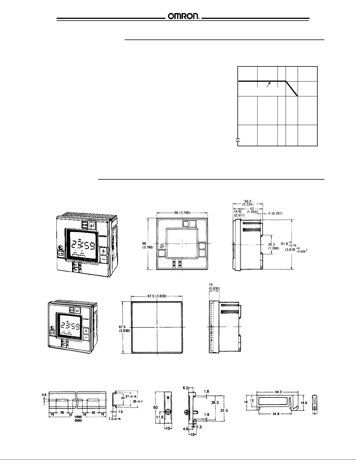
■ AMBIENT OPERATING TEMPERATURE AND CARRY CURRENT
H5L
The upper limit of the ambient operating temperature
must be derated when a large carry current is being
applied. This case occurs when both circuits are
energized simultaneously.
Dimensions
Unit: mm (inch)
■ TIMER
60°C
(140°F)
55°C
(131°F)
When both circuits are
energized simultaneously
50°C
(122°F)
40°C
(104°F)
Maximum ambient operating temperature
0
5
Carry current AC/DC (A)
10
20
15
12
■ PROTECTIVE COVER
The hard plastic cover prevents
accidental resetting. It also
shields the front panel from dirt
and water. The cover is
intended for use in areas where
unusual service conditions do
not exist.
■
MOUNTING TRACK AND ACCESSORIES
PFP-100N/PFP-50N DIN Rail PFP-M End Plate PFP-S Spacer
3
Page 4
H5L
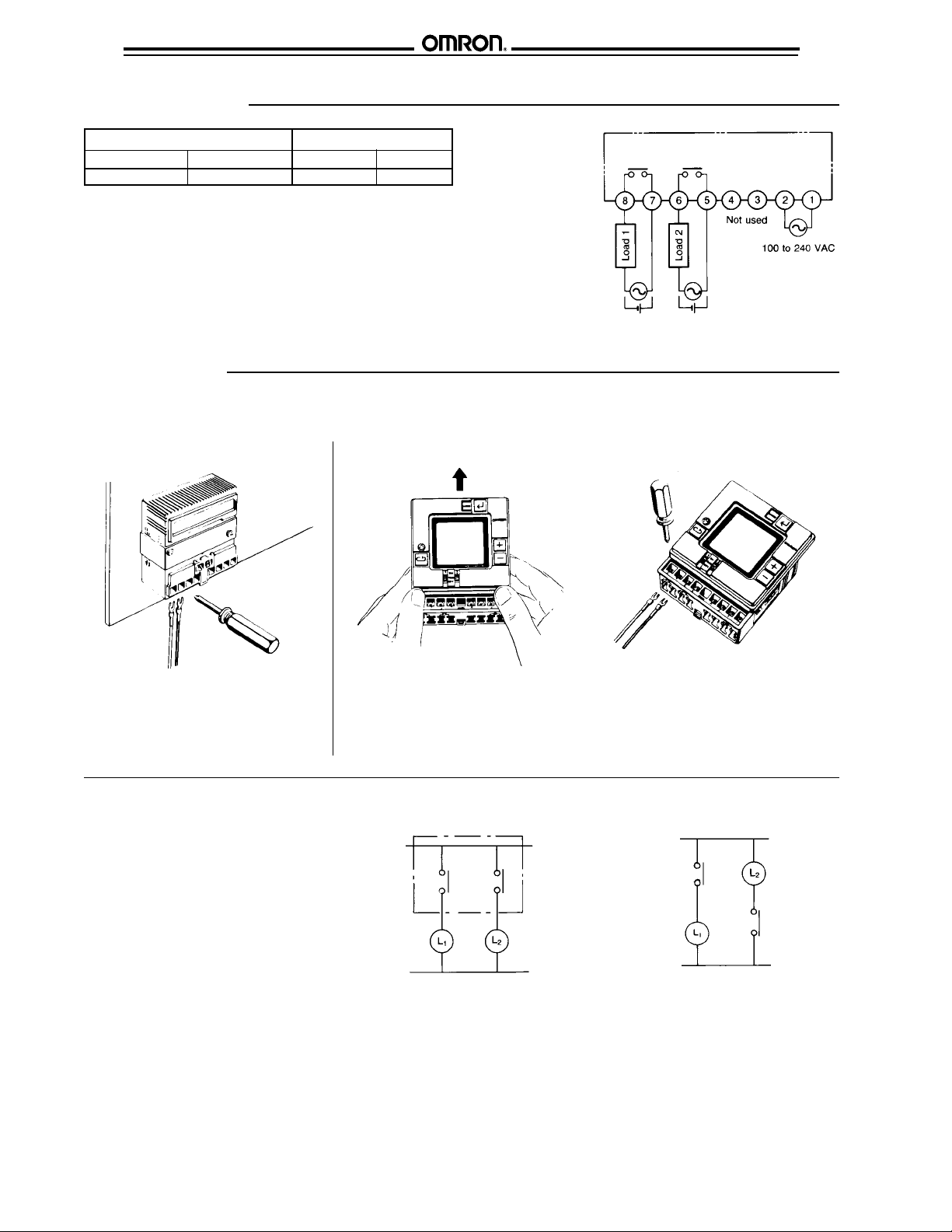
Connections
Power supply terminal numbers Output terminal numbers
AC (common) AC (hot) Load 1 Load 2
2 1 7 and 8 5 and 6
H5L
If operating conditions exceed the noise
values at right, connect a surge absorber to
prevent malfunction or damage to the
timer. This is especially important when
inductive loads are being switched by the
timer.
Installation
■ WIRING
Power Supply
For panel mounting
Noise voltage: 2 KV
Pulse width: 100 ns
Rise time:1 ns
For track and surface mounting
Wire the H5L timer from the rear once the
unit is mounted in the panel.
Output Circuits
Perform wiring so that the potential across
the output contacts is the same. This
prevents short-circuiting of the contacts.
Refer to the connections chart above for
terminal numbers.
Wire the H5L timer from the front when the unit is track or surface mounted.
1. Loosen the screw above the "cycle" key on the left front.
2. Slide the upper part of the housing upward about 15 mm (0.59 in).
3. Step 2 exposes the terminals. Perform the wiring.
4. Slide the upper part of the housing to the original position, then tighten the screw.
Correct
Incorrect
4
Page 5

H5L
Operation
H5L
■ NOMENCLATURE
Day of week
display
Output status indication
Output ON
Output OFF
Invalid instruction
written to a step
■ KEY OPERATIONS
Key Name Function
MODE
+
-
Mode key Changes program mode
Write key To write the set data using the plus and/or minus key
Reads out the set program
Plus key Plus key increments displayed digits
Minus key decrements displayed digits
Minus key When the plus key is held down, the displayed digit increments continuously; when the
minus key is held down, the displayed digit decrements continuously
When specifying output, the plus key specifies output ON, the minus key specifies output
OFF. If the same key is pressed twice, the output specification becomes invalid, so
neither ON nor OFF is set.
Cycle key Selects the cycle program.
Mode display
Cycle key
<
RUN mode
Second circuit
weekday setting
mode
<
Current time
setting mode
Second circuit
<
operation
setting mode
Mode key
Write key
Plus key
Minus key
Manual override switch
<
First circuit operation
setting mode
First weekday
<<
setting mode
Manual
override
switch
ON: Turns ON output regardless of program
RUN: Executes program
OFF: Turns OFF output regardless of program
Each circuit can be operated independently
5
Page 6

H5L
H5L
■ PROGRAMMING SEQUENCE
The H5L weekly timer has six program modes. Use the mode key
to change the modes. Use the write key, plus and minus keys and
cycle key for programming in each mode.
Mode sequence Programming details
Cycle program
The cycle program in H5L can be used to repeat ON and OFF
output patterns for a length of time. A cycle program consists of
four steps: Start time, ON time, OFF time and Stop time.
Setting Cycle Program
Set the cycle program with the following four steps:
Setting
start time
Set the "hour" and "minute"
of start time using the +
and - keys.
↓
Setting Set the ON time of the cycle
ON time frequency in the order of
"hour" and "minute".
↓
Setting Set the OFF time of the cycle
OFF time frequency in the order of
"hour" and "minute".
NOTE: The H5L operates according to the program already set,
even while another program is being set. The output
status display shows the program being set. The actual
output status may not agree with the displayed status
during programming.
↓
Setting Set the stop time of the
stop time cycle program.
↓
Normal After the four steps are set,
program H5L automatically returns to
mode normal program mode.
Cautions on Using Cycle Programs
1. When the current time is included within the set cycle period,
the cycle operation starts (output turns ON) on completing
the cycle program setting (when stop time is written).
2. When any of the following occurs during a cycle period, the
cycle operation restarts from output ON:
Recovery after power failure
Current time adjustment
Change of start or stop time of the cycle program
during operation
For this reason, if the cycle program is set in such a manner
that outputs 1 and 2 have a phase difference, as shown
below, the phase difference is changed automatically
when any of the abovementioned conditions occur. We
recommend using cycle programs sequentially.
3. The cycle period (from start time to stop time) must not be a
multiple of the cycle frequency (ON time plus OFF time). The
cycle period can be set between 1 minute and 24 hours.
4. ON time as well as OFF time can be set within a range of
1 minute to 23 hours 59 minutes.
6
Page 7

H5L
■ DELETING ON/OFF PROGRAM STEPS
Use the MODE and WRITE keys to advance to the output status
indicator of the steps to be deleted. Use the + and
– keys to make the output status indicator invalid (no bar).
Press the WRITE key and the step is deleted.
■ DELETING CYCLE PROGRAM STEPS
Use the MODE and WRITE keys to advance to the first step of
the cycle program. Push the CYCLE key followed by the WRITE
key. All four stpes of the cycle program are deleted.
H5L
■ CLEARING THE PROGRAM
The H5L cannot be cleared by cycling the power OFF/ON since a
built-in battery protects the memory. In order to clear the contents
of the memory, follow these steps.
1. Loosen the screw above the cycle key on the left side of timer
front, then slide the front panel up.
2. Turn the timer over and depress the metal strip at the top near
the area of the small hole.
3. The contents of the memory are cleared and the display will
show all of the graphics for approximately 5 seconds. This
may be used for a quick visual check.
CAUTION: Use the front panel override switches to control the
Programming Example
■ CREATE A TIMING CHART BEFORE PROGRAMMING
Always create a timing chart before
programming the timer. The hardcopy
provides an excellent tool if troubleshooting is needed. If changes to
the programming are necessary, having
the hardcopy will make the job easier.
The timer will generate outputs during
programming depending on the logic of
the current or previous program. Use
the output override switches to
manually control the outputs if this is
undesirable.
Sample Timing Chart Blank
First circuit
6912
3
0
ON
OFF
Second circuit
6912
3
0
ON
OFF
Press here to clear program
↓
status of the outputs when clearing the program. This
maintains the desired functions without interruption.
15 18 21
18
15
24
Sun. Mon. Tue. Wed.Thu. Fri. Sat.
24
21
Sun. Mon. Tue. Wed.Thu. Fri. Sat.
■ SETTING ON AND OFF PROGRAMS, CYCLE PROGRAMS
In this example, the first circuit is programmed to turn ON at 7:40 and OFF at
19:30. This circuit is operated from Monday through Friday and stopped on
Saturday and Sunday.
The second circuit is cyclically operated with each parameter set as follows:
Start time: 6:50
ON time: 5 minutes
OFF time: 20 minutes
Stop time: 20:30
The second circuit is stopped from operating on Sunday and operated from
Monday through Saturday. The current time is assumed to be 11:15 a.m. on
Tuesday.
7
Page 8

H5L
Creating Timing Chart
Writing the Program
Setting the current time
H5L
First circuit
Second circuit
To set the current time, "day of the week", "hour", and "minute" must be specified.
First, turn on the power to the H5L. Press the Mode key for more than 1 sec. The
TIM ADJ indicator is displayed.
Set 11:15 on Tuesday, the current time in example1.
Start with setting the day of the week. The blinking indicator indicates the parameter
that can be set. Set the current day of the week to Tuesday by pressing the + or –
key.
When "TUE" is displayed, press the Write key to store the current day of the week in
memory. Then the "hour" indicator will flash at this time and the "day of the week"
indicator will stop blinking.
Set the current hour to 11 by pressing the + or – key, followed by the Write key.
At this time, the "minute" indicator will blink. Set the current minute to 15 by pressing
the + key or – key, followed by the Write key.
This completes the current time setting.
Next, program the first circuit's operation.
8
Page 9

H5L
First Circuit Operation Setting
To program the operation of the first circuit, "hour", "minute", and "output" must be
specified.
Press the MODE key to set the H5L in PROG 1 mode. The display will be as shown
on the left.
Since the first circuit is turned ON at 7:40, set the "hour" to 7 by pressing the + or –
key and then store it in memory by using the Write key.
Then "minute" will start blinking. Set it to 40 by using the + or – key and store it in
memory by pressing the Write key.
Now, the output status indicator will blink. Set the output to the ON status with the +
key followed by the Write key.
(If the + key is pressed twice at this time, the display will give an invalid indication
( ). Then if the Write key is pressed, this program will be deleted.)
H5L
The display returns to the initial status as shown on the left and waits for the next
program step to be input.
Since the first circuit should be turned OFF at 19:30, set the hour to 19 and the minute
to 30 by using the + or – key and then the Write key.
Now the output status indicator starts blinking. Set the output to OFF status by the –
key and store it in memory by the Write key.
The display returns to the initial status and waits for the next program step to be input.
As the first circuit operation setting is completed, let us turn to setting the "day of the
week".
9
Page 10

H5L
Second Circuit Operation Setting
Press the MODE key to set the H5L in PROG 2 mode. The display appears as shown
on the left.
In example 1, as the second circuit is to be cyclically operated, specify the cycle
program by pressing the Cycle key.
START
Set the start time (6:50) first. Set the hour to 6 and the minute to 50 by pressing the +
or – key. Write each set value with the Write key.
START
Then, set the ON time, which is 0:05 in this example.
H5L
STOP
Write the hour of 0 by pressing the Write key.
Set the minute to 5 and store it in memory by using the Write key.
Next, set the OFF time.
The OFF time is to be 0:20.
Finally, by pressing the Write key, set the hour to 0. In addition, set the minute to 20
by pressing the + or – key. Write it by pressing the Write key.
Next, set the time at which the cyclic circuit operation is to be stopped. The stop time
is to be 20:30.
Set the hour to 20 by pressing the + or – key followed by the Write key. Set the
minute to 30 by the + or – key followed by the Write key.
10
STOP
Now, the programming of the cyclic operation is completed.
The display is as shown on the left and waits for the next program to be input. Since
the second circuit operation in example 1 has been completed, let's move to setting
the day of the week.
Page 11

H5L
Second Circuit Day-of-the-Week Setting
Press the MODE key to set the H5L in the DAY SET mode of the PROG 2 mode.
The display will be as shown on the left.
As the initial condition, the second circuit is to be operated on all the days of the
week, which means all the indications by the day indicators are reverse video except
that of the SUN indicator which blinks.
In example 1, the second circuit is not operated on Sunday but on all the other days;
set Sunday to be stopped accordingly using the – key and the Write key.
Then, the MON indicator starts blinking. Since on Monday through Saturday the
operation is set to be activated as the initial condition, there is no more need to set the
operation.
Running the Program
Now all the parameters have been programmed as in example 1. Press the MODE
key to set the H5L in the RUN mode.
The display will be as shown on the left.
The output status indicators show the current status of both outputs.
H5L
■ PROGRAMMING ERRORS
1. When the OFF time is set at the same hour and minute as the ON
time, "hour" indicator blinks twice the normal rate for showing a
program error. In this case, set the OFF (or ON) time again.
2. When the ON/OFF program is superimposed on the cyclic period
(from cycle start to cycle stop), the program error is indicated as
shown below. Set the "hour" and "minute" outside the cyclic
period.
3. When a cycle program is superimposed on the existing program
(ON time, OFF time, or cycle program), the program error is
indicated as shown below. Change the start time or stop time of
the cycle program not to overlap the other existing program.
11
Page 12

H5L
Mounting
The H5L timer comes with mounting brackets for panel and surface mounting.
A slot on the back of the case allows H5L to be track mounted.
■ PANEL MOUNTING
Use the U-shaped mounting bracket supplied.
■ SURFACE MOUNTING
Use the straight mounting bracket supplied.
Dimensions
Flush mounting
bracket (supplied)
H5L 2433982-8
H5L
Panel cutout
■ TRACK MOUNTING
Hook the upper part on the rear surface to the upper edge of the
mounting track and press the unit down.
Surface mounting
bracket (supplied)
H5L 2433983-6
59.8 (2.354)
Mounting holes
12
Page 13

H5L
H5L
NOTE: ALL DIMENSIONS ARE IN MILLIMETERS. To convert millimeters into inches divide by 25.4.
Omron Europe B.V. EMA-ISD, tel:+31 23 5681390, fax:+31 23 5681397, http://www.eu.omron.com/ema
Cat . No. GC TI8 11/97 Specifications subject to change without notice. P r inted in the U. S.A.
13
 Loading...