

Page 1
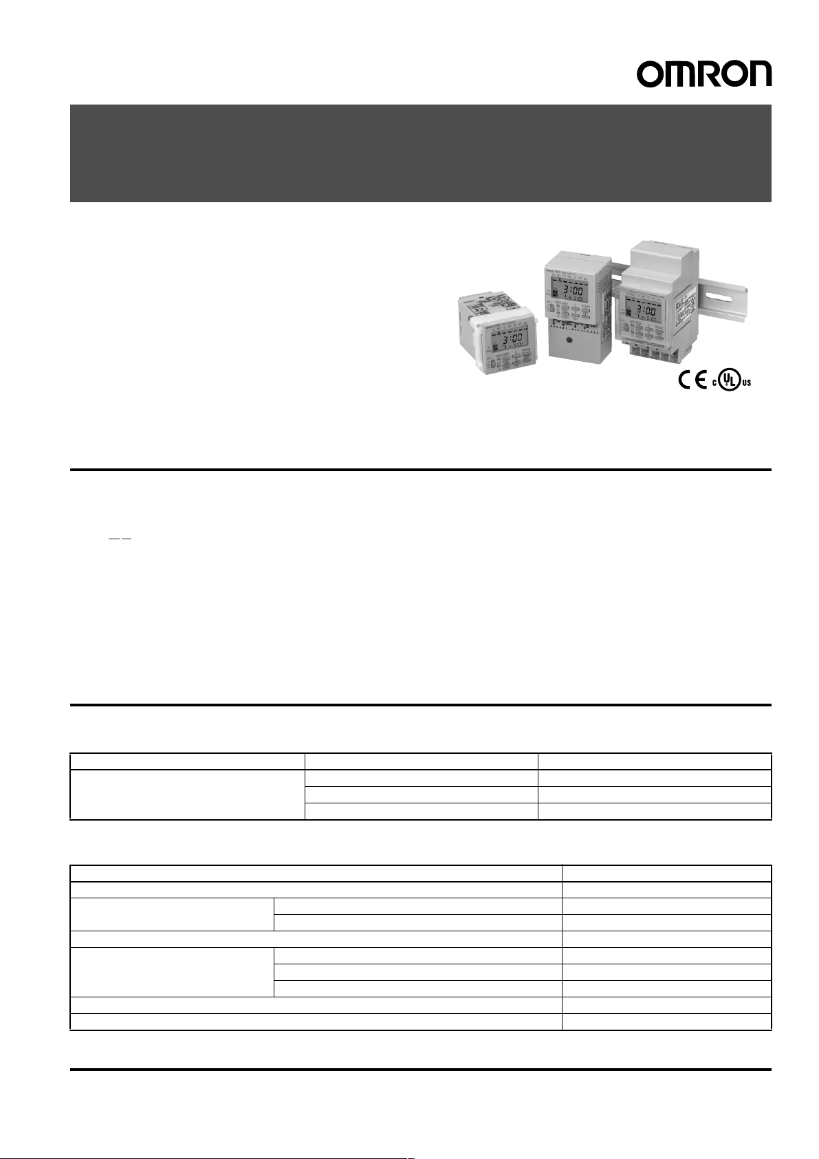
Digital Daily Time Switch
H5F
Daily Time Control with Simple Operations
(Operation Day Selection Possible)
• Up to 12 ON/OFF operations (24 for pulse-output operation).
• Special holidays can be handled easily with the holiday setting
function.
• Adjustments f o r sudde n sch edule c hange s can be ma de eas ily
using output override and automatic return operation.
• The operation progr am can be che ck ed ea sily w ith the progra m
check function.
• Enables pulse output operation and summer time setting.
• Incorporates finger-safe terminals.
• Conforms to UL, CSA, and CE marking.
• Meets a variety of mounting requirements: flush mounting, surface mounting, and DIN track mounting.
Model Number Structure
■Model Number Lege nd
H5F-@B
12
1. Mounting method
None: Flush mounting
F: Surface mounting
K: Surface mounting/track mounting
2. Language
B: English
Ordering Information
■List of Models
Wiring Mounting method Model
Screw terminals Flush mounting H5F-B
Surface mounting H5F-FB
Surface mounting/track mounting H5F-KB
■Accessories (Order Separately)
Name Models
Soft cover Y92A-48F1
Hard cover For H5F-B Y92A-48
For H5F-FB/-KB Y92A-48E (See note 1.)
Flush Mounting Adapter (See note 2.) Y92F-30
Mounting Track 50 cm (l)
1 m (l)
1 m (l)
End Plate PFP-M
Spacer PFP-S
Note: 1. Supplied with H5F-KB model.
2. Supplied with H5F-B (flush-mounting) model.
´ 7.3 mm (t) PFP-50N
´ 7.3 mm (t) PFP-100N
´ 16 mm (t) PFP-100N2
Digital Daily Time Switch H5F 1
Page 2
Specifications
■Ratings
Rated supply voltage 100 to 240 VAC (50/60 Hz)
Operating voltage range 85% to 110% of rated supply voltage
Power consumption Approx. 2.4 VA at 264 VAC
Control outputs Contact output: SPST-NO, 15 A at 250 VAC, resistive load, 10 A at 24 VDC, resistive load
External connections Screw terminals (M3.5 screw)
Terminal screw tightening torque 0.98 to 1.17 N · m
■Characteristics
Accuracy of operating time ±0.01% ±0.05 s max. (see note 1)
Setting error
Influence of voltage
Influence of temperature
Cyclic error Monthly differen ce
Memory protection Continuous use: 5 years min. (at 25
Insulation resista nc e 100 M
Dielectric strength 2,000 V A C , 50/6 0 Hz f or 1 min (betw een curren t-carrying terminals and e xpos ed non-cu rrent-car rying metal parts and
Noise immunity 1.5 kV (between power terminals)
Vibration resistance Destruction:10 to 55 Hz with 0.375-mm single amplitude, four cycles each in three directions (8 minutes per cycle)
Shock resistance
Ambient temperature Operating:–10
Ambient humidity Operating: 35% to 85%
Life expectancy Mechanical (at 20
Approved safety standards UL508/Listing, CSA C22.2 No. 14, conforms to EN61010-1 (Pollution degr ee 2/overvoltage category II)
EMC (EMI) EN61326
Case color Light gray (Munsell 5Y7/1)
Weight H5F-B: approx. 115 g; H5F-KB: approx. 160 g; H5F-FB: approx. 130 g
Note: 1. The total error including the repeat accuracy, setting error, variation due to voltage change, and variation due to temperature change is
±0.01%±0.05 s max. ±0.01% also indicates an error in the time interval of a set time.
2. The total time when power is not being supplied.
Minimum applied load: 100 mA at 5 VDC (failure level: P, reference value)
NEMA A300 Pilot Duty, 1/3 HP at 120 VAC
±15 s (at 25°C)
(lithium ba tt ery)
W min. (between current-carrying t erminals and exposed non-current-carrying metal parts, between operating
power supply circui t and control output circuit and between non-continuous contacts )
between operating power supply circuit and control output circuit)
1,000 VAC, 50/60 Hz for 1 min (between non-continuous contacts)
Square-wave noise by noise simulator (pulse width: 100 ns/1
Malfunction:10 to 55 Hz with 0.25-mm single amplitude for 10 minutes eac h in three directions
Destruction:300 m/s
Malfunction:100 m/s
Storage: –25
100,000 operations min.
Electr ical (at 20
50,000 operations mi n. (15 A, 250 VAC, resistive load)
50,000 operations mi n. (1 HP, 250 VAC, motor load)
50,000 operations min. (10 A, 250 VAC, inductive load (cos
50,000 operations min. (100 W, 100 VAC, lamp load)
10,000 operations min. (300 W, 100 VAC, lamp load)
Conforms to VDE0106/P100 (finger protection).
Conforms to Electrical Appliance and Material Safety Law (for Japan)
Emission Enclosure: EN55011 Group 1 class A
Emission AC mains: EN55011 Group 1 class A
(EMS) EN61326
Immunity ESD: EN61000-4-2: 4 kV contact discharge (level 2)
Immunity RF-interference: EN61000-4-3: 10 V/m (Amplitude-modulated, 80 MHz to 1 GHz,
Immunity Conducted
Disturbance: EN61000-4-6: 10 V (0.15 to 80 MHz) (according to EN61000-6-2)
Immunity Burst: EN61000-4-4: 2 kV power-line (le vel 3)
Immunity Surge: EN61000-4-5: 1 kV line to lines (power and out put lines) (level 2) ;
Immunity Voltage Dip/Interrupti on: EN61000-4-11: 0.5 cycle, 100% (rat ed voltage)
Immunity Magnetic Power Field: EN61000-4-8: 30 A/m
2
3 times each in 6 directions
2
3 times each in 6 directions
°C to 55°C (with no icing)
°C to 65°C (with no icing)
°C):
°C):
°C); Power-interruption rate of 50%: 10 years min. (at 25°C) (see note 2)
ms, 1-ns rise)
f = 0.7))
8 kV air discharge (level 3)
1.4 to 2 GHz) (level 3)
1 kV I/O signal-line (le vel 4)
2 kV line to ground (power an d output lines) (level 3)
2 Digital Daily Time Switch H5F
Page 3

Connections
■Terminal Arrangement
Flush Mounting Models
H5F-B H5F-FB
(Rear View)
Power source
100 to 240 VAC
Load
Power supply
of load
Surface Mounting Models
(Front View)
H5FTIME SWITCH
SU MO TU WE TH FR SA
PM
3 00
OUT
ON
PM
POWER
OUT
ON
AUTO
OFF
Power source
100 to 240 VAC
5 00
PW
P
TMR/
MODE
CLR
P
m
/ WD
WRITE
dhSELECT
TESTHOLIDAY+1h
Load
Power supply
of load
Surface Mounting/Track Mounting Models
H5F-KB
(Front View)
H5FTIME SWITCH
SU MO TU WE TH FR SA
PM
3 00
ON
OUT
POWER
OUT
ON
AUTO
OFF
Power source
100 to 240 VAC
5 00
PM
PW
P
TMR/
MODE
SELECT
CLR
P
m
/ WD
h
WRITE
d
TESTHOLIDAY+1h
Load
Power supply
of load
Note: 1. The Time Switch uses M3.5 terminals.
2. The Time Switch output is no-voltage contact output. An external power supply is required to drive the load.
3. Applicable wire: 600-V vinyl-insulated wire (solid wire or twisted wire, copper), 14 to 24 AWG, 2 wires max. per terminal.
4. Applicable tightening torque: 0.98 to 1.17 N·m.
5. Recommended fuse: T2A, 250 VAC, time delay, low breaking capacity.
Operation
■Operation
Operation method Digital quartz
Time range 24 h
Operation 1. Daily operation (Multiple-day operation possible.)
Display 1. Day, hours (12-hour (am/pm) or 24-hour clock), minutes (0:00 to 11:59 a.m./ 0:00 to 11:59 p.m.,
Other func tions Program check function, summer time function
Number of circuits 1 independent circuit
Minimum setting unit 1 min
Minimum set interval 1 min
Number of operations that can be set 24 (see note)
Note: Up to 12 ON/OFF operations are possible per day. (For pulse-output operation, the number is 24.)
´ 7 days (Operation days can be specified.)
2. Pulse-output operation (Pulse width can be set in units of 1 s from 1 to 59 s and in units of 1min
from 1 to 60 min.)
3. Partial operation on specified day (One or some of the operations for certain days can also be
executed on other days.)
4. Forced ON/OFF operation
5. Holiday operation
6. Output override and automatic return operation
0:00 to 23:59)
2. Digital display by LCD. Character height: 8 mm
3. Digital display of present time and time schedules for operation
4. Timing chart display of present time and time schedules for operation
Digital Daily Time Switch H5F 3
Page 4
■Operation Function s
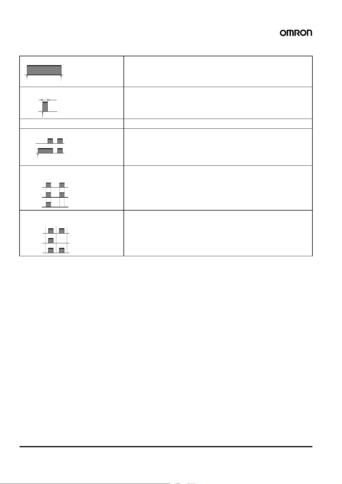
Timer operation (ON/OFF operation) Controls the output according to preset of ON and OFF times
• Minimum setting unit: 1 min
• Up to 12 ON/OFF operations are possible per day.
ON time
OFF time
Pulse-output operation Output turns ON for a fixed period (pulse width) at the set time.
Pulse width
ON time
• Pulse width: 1 to 59 s, or 1 to 60 min. (The same pulse width setting is used for all types of
output operation.)
• The pulse width can be set in units of 1 s or 1 min.
• Up to 24 pulse-output operations are possible per day.
Forced ON/OFF operation Forcibly turns ON/OFF the output by the output ON/OFF switch.
Override and automatic return operation Using the output ON/OFF switch and the Write Key, control output is held in the ON state until
Regular
program
Output
operation
Start of override and
automatic return operation
the next OFF time.
• It is also possible to hold the control output in the OFF state until the next ON time.
• Operation after the output turns OFF (or ON) will be based on the regular program.
• This function can be used with pulse-output operation.
Partial operation on specified day The Time Switch operates according to only some of the programs on a user-specified day.
(Convenient, for e xample, for executing a half-day operation on Saturday.)
• It is not possible to set operation to be executed only on the specified day.
• This function can be used with pulse-output operation.
Regular
program
Operation on
operation day
Operation on
specified day
Program 1
(special)
Program 2
Holiday setting It is possible to set a day in the present week as a holiday (i.e., a non-operation day: output
OFF regardless of the settings). When that day has passed, operation will continue according
to the regular program, and operation will be executed as normal on that day from the foll owing week
• This function can be used with pulse-output operation.
Regular
program
Operation in
present week
Operation from
next week
Operation on
operation day
Operation
on holiday
Note: B oth the timer operation and the pulse-output operation cannot be programmed together.
■Operation When Power Turn s OF F
1. The time and settings are backed up using a lithium battery.
2. The display stays ON but the output turns OFF.
3. Settings for all types of operation except override and automatic
return operation are possible.
4 Digital Daily Time Switch H5F
Page 5
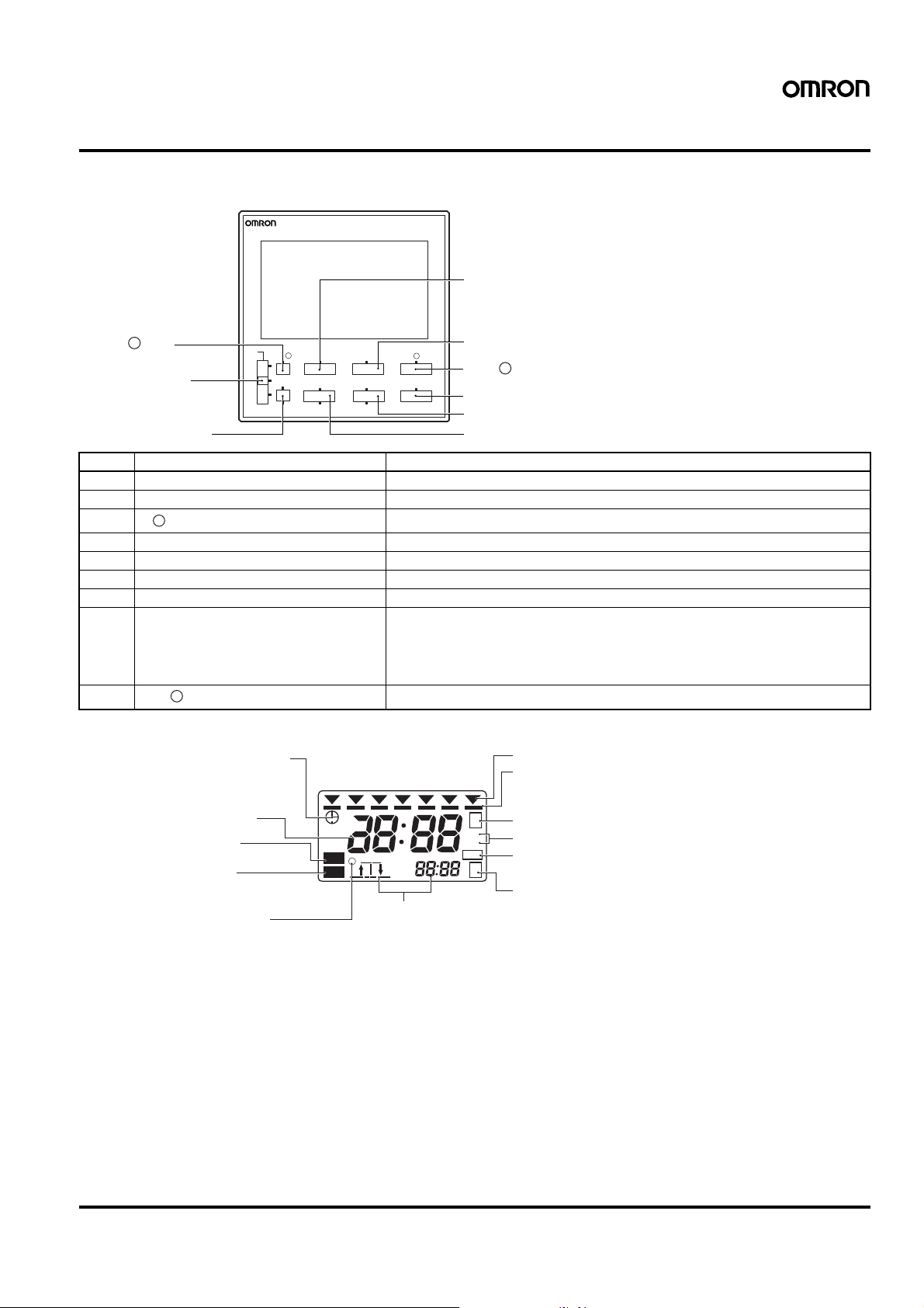
Nomenclature
Front Panel
(Actual Size)
H5FTIME SWITCH
SU MO TU WE TH FR SA
A Mode Key
OUT
P
I TMR/ Key
H Output ON/OFF
Switch
G CLR/+1h Key
No. Name Function
A Mode Key Switches between time adjustment mode, the operation setting modes, and run mode.
B h (Hour) Key Sets hours or switches between 12-hour (am/pm) and 24-hour display.
C Sets minutes or a pulse time width.
P
m/ WD (Minute/Pulse Time Width) Key
D Write Key Writes the set data to memory or confirms settings with the program check function.
E d/Test (Day Shift/Program Test) Key Moves the cursor to specify a day or starts the program check function.
F Select/Holiday Key Specifies or cancels a specified day or switches to holiday setting mode.
G CLR/+1h (Clear/Summer Time) Key Erases the set data and initializes the day of operation or sets/clears summer time.
H Output ON/OFF switch ON: Turns on the output regardless of the setting.
I Selects timer operation or pulse-output operation.
P
TMR/ (Timer/Pulse output) Key
POWER
OUT
ON
AUTO
OFF
TMR/
CLR
+1h
P
MODE
SELECT
HOLIDAY
B h Key
P
C m/ WD Key
D Write Key
E d/Test Key
TEST
P
m/
h
d
WD
WRITE
F Select/Holiday Key
AUTO: Turns on/off the output according to the setting.
OFF: Turns off the output regardless of the setting.
Override and automatic return operation can be executed by using this key in combination with the Write Key.
Display
Time Adjustment Mode Indicator
Displays the Present Time,
Operation Time, and Time Width
Output Indicator
Lit when control output is ON.
Power Indicator
Lit when power is supplied
to the Time Switch.
Pulse Operation Indicator
Lit: Pulse-output operation
Not lit: Timer operation
Present Day Indicator
Operation Day Indicator
SU MO TU WE TH FR SA
AM
PM
ON
PW
P
AM
PM
+1h
Lit: Operation day
Not lit: Non-operation day
Flashing: Specified operation day
S
s
m
Partial Operation on Specified Day Indicator
Pulse Width Unit Indicator
Summer Time Indicator
P
Lit when set to summer time.
Operation Setting Mode Indicator
Next Operation Indicators
Run mode: Displays the direction (i.e., ON or
Operation time setting mode: Displays the program number for
Holiday setting mode: Displays hday (hday) when the
Program check: Displays test (test) during
OFF) and time of the next output
operation.
the setting.
Time Switch is in holiday setting
mode.
program check.
Digital Daily Time Switch H5F 5
Page 6

Dimensions
Note: A ll units are in millimeters unless otherwise indicated.
H5F-B (provided with Y92F-30 Flush Mounting Adap te r)
(Flush Mounting)
H5F
T
IM
E S
W
ITC
H
SU
M
O
T
U
W
E
TH
FR
S
A
P
M
3
OUT
00
O
N
P
O
W
E
R
P
W
P
M
5
0
0
OUT
T
M
R
/
P
MOD
E
h
ON
m/ WD
AUTO
OFF
P
CLR
SE
LECT
d
SET
+1h
HOLIDAY
TEST
48
H5F-FB
(Surface Mounting)
H5F
T
I
M
E
S
W
IT
C
H
S
U
M
O
T
U
W
E
T
H
F
R
S
A
P
M
3
O
U
00
T
O
N
P
O
W
E
R
P
W
P
M
5
0
0
O
U
T
T
M
R
/
P
M
O
D
h
E
m
P
O
A
U
T
O
F
/ W
N
O
F
1
D
C
L
R
S
E
L
E
C
T
d
S
E
T
+
1
h
H
O
L
ID
A
Y
T
E
S
T
1
0
0
to
2
4
0
V
A
C
5
0
/6
0
H
z
1
5
A
2
2
.4
5
0
V
V
A
A
m
C
a
x
2
.
1
0
A
2
4
V
D
C
3
R
E
S
.
4
50
92
Y92A-48 Hard Cover (sold separately)
48
6
50.6
50
Y92A-48E
Hard Cover
(sold separately)
49
42.1
63.7
84.8
88.7
14
Terminal cover (provided)
44.8
37.7
Note: The Time Switch
uses M3.5
terminals.
Mounting Dimensions
(50)
(92)
Panel Cutout Dimensions
(according to DIN43700)
+0.5
45
+0.5
45
Note: Recommended panel thickness: 1 to 5 mm.
8
76
1.5
H5F-KB
(Surface/Track Mounting)
H5F
TIME SWITCH
S
U
M
O
T
U
W
E
T
H
F
R
S
A
PM
3
O
U
T
00
O
N
P
O
W
E
R
P
W
P
M
5
00
O
U
T
T
M
R
/
P
M
O
D
h
E
m
P
/
O
N
A
U
T
O
O
F
F
W
D
C
L
R
S
E
L
E
C
T
d
S
E
T
+
1
h
H
O
L
ID
A
Y
T
E
S
T
1
2
.4
V
A
m
a
x
2
.
3
R
E
S
.
4
101.2
Terminal cover
(provided)
Wiring cutout sections:
Cut out as required for wiring.
50
Y92A-48E
Hard Cover
(provided)
68
50.5
Terminal cover (provided)
31
Note: The Time Switch
uses M3.5
terminals.
M4 tapping screws provided.
Approximate pilot hole dimensions:
Panel thickness of 0.8 to 1.2 mm: 3.6 mm dia.
Panel thickness of 1.6 to 4.0 mm: 3.7 mm dia.
Mounting Hole Cutout Dimensions
73
42
50
35.3
90
43.1
60
25
(101.2)
117.4
104 to 106
(50.5)
M4 tapping screws provided.
Approximate pilot hole dimensions:
Panel thickness of 0.8 to 1.2 mm: 3.6 mm dia.
Panel thickness of 1.6 to 4.0 mm: 3.7 mm dia.
6 Digital Daily Time Switch H5F
Page 7

■Accessories (Order Separately)
Note: Depending on the operating environment, resin products may deteriorate, contract, or harden. They must be replaced on a regular basis .
Soft Cover
Y92A-48F1
Settings can be changed by pressing on the front of the Cover. The
settings are harder to change, however, with the Cover mounted.
Confirm that this does not hamper operation. Although the Soft
Cover provides protection equivalent to IP54F, do not use the Time
Switch in locations where it may be directly subject to splashes of oil.
Flush Mounting Adapter
(provided with H5F-B)
Y92F-30
The Flush Mounting Adapter can be purchased individually if it is lost
or damaged.
Hard Cover
(provided with H5F-KB)
Y92F-48 (for H5F-B)
Y92A-48E (for H5F-FB/-KB)
Mounting T rack
PFP-100N, PFP-50N
4.5
15 25 25
10
1,000 (500)
(see note)
25
10
Note: The values shown in parentheses are for the PFP-50N.
7.3±0.15
35±0.3
25
*
27±0.15
1
End Plate
PFP-M
10
6.2
1.8
1
1.3
4.8
1.8
35.5 35.3
50
11.5
10
M4 x 8
pan head
screw
PFP-100N2
4.5
15 25 25
Spacer
PFP-S
10 10
25 25
1,000
16
1
34.8
29.2
1.5
24
27
35±0.3
15
5
16
12
44.3
16.5
Digital Daily Time Switch H5F 7
Page 8

Precautions
!Caution
Do not touch any of the terminals while power is being supplied.
Doing so may result in electric shock. Be sure to mount the terminal cover after wiring.
Do not use the Time Switch in locations s ubject to flammable or
explosive gases. Doing so may result in explosion.
Do not disassemble, repair, or modify the Time Switch. Doing so
may result in electric shock, fire, or malfunction.
Before changing times or other settings while power is being s upplied, either turn OFF the power on the load side or set the output
ON/OFF switch to OFF and confirm the safety of the system.
The life expectancy of the output relays depends on the switching
capacity and switching conditions. Consider the actual application
conditions and use the Time Switch within the rated load and electrical service life. If using the Time Switch beyond its ratings is
unavoidable, use it together with an electromagnetic switch or contactor as shown in the following diagram.
Electromagnetic
contactor or
electromagnetic
switch
Crossover
Power supply
Load
Power supply
Circuit
H5F
Using the Time Switch beyond its life expectancy may result in contact deposition or burning.
Do not disassemble the Time Switch, deform the Time Switch by
applying pressure, heat the Time Switch to temperatures above
100
°C, or incinerate the Time Switch. Doing any of these may
cause the built-in lithium battery to ignite or rupture.
■Wiring
• Be sure to wire the terminals correctly.
• Do not connect more than two crimp terminals to each Time Switch
terminal. Faulty contact may result in burn injury or fire.
• Perform wiring using appropriate wires of the type specified in this
document. Using a different type of wire may result in burn injury or
fire due to abnormal heat generation.
■Power Supplies
• Make sure that the fluctuation of the supply voltage is within the
permissible range.
• Make sure that the voltage applied is within the specified range,
otherwise the internal elements of the Time Switch may be damaged.
• Apply the power supply voltage through a breaker, relay or switch in
such a way that the voltage reaches a fixed value immediately, otherwise they may not be reset or a Time Switch error may result.
• When the power is turned ON, an inrush current will flow for a short
time (approx. 2 A for 0.3 ms at 264 VAC). Depending on the power
supply capacity, operation may not start. Be sure to use a power
supply with a sufficient capacity and a breaker.
■Operat ing Environment
• Do not use t he Time Switch in locations where condens ation may
occur due to high humidity or where temperature changes are
severe.
• Do not leave the Time Switch for long periods (i.e., one month or
longer) at a high temperature with output current in the ON state.
Doing so may result in the premature deterioration of internal components (e.g., electrolytic capacitors).
• Separate the Time Switch from any potential sources of noise, such
as high-voltage lines. When using inductive loads (e.g., electromagnetic relays), connect noise-absorbing elements (resistor and
capacitor) to both ends of the coil.
• Separate the Time Switch from t he sour ce of st atic electr icity when
using the Time Switch in an environment where a large amount of
static electricity is produced (e.g., forming compounds, powders, or
fluid materials being transported by pipe).
• Use the Time Switch within the ratings specified for temperature
and humidity.
• Do not use t he Time Switch in environments subject to shocks or
vibration beyond the ranges specified in this document.
• Do not us e the Time Switch in locations subject to dust, corrosive
gases, or direct sunlight.
• Store at the specified temperature. If the H5F has been stored at a
temperature of less than
-10°C, allow the H5F to stand at room
temperature for at least 3 hours before use.
• This Time Switch is not waterproof or oil-proof. Do not use it in
locations where water or oil may enter the Time Switch interior.
• Organic solvents (such as paint thinner), as well as very acidic or
basic solutions might damage the outer casing of the H5F.
■Installation
• Mounting the Time Switches side-by-side may reduce the life
expectancies of internal components.
• When using heat ers, be sure to use a therm al switch for the load
circuit.
• When driving an inductive load (e.g., coil), a surge voltage is generated when the contacts (i.e., Time Switch output) are switched, and
in some cases this may damage other devices connected to the
Time Switch or the same line. Absorb the surge with a capacitor
and resistor as shown in the following diagram.
Time Switch output
C
Power supply
As a rough guide, the capacitor (C) and resistor (R) should have the
following specifications:
C: 0.5 to 1
R: 0.5 to 1
mF for a switching current of 1 A
W for a switching voltage of 1 V
Use a capacitor with a dielectric strength appropriate for the power
supply voltage. Use an AC-type capacitor with AC circuits. There
may be cases where, due to inconsistencies in the nature and characteristics of the load, delays in restoring the load may cause problems. Be sure to confirm that correct operation is possible under the
actual operating conditions.
Inductive
load
R
8 Digital Daily Time Switch H5F
Page 9

■Precautions for EN6101 0- 1
Conformance
The H5F Time Switch conforms to EN61010-1 provided that the following conditions are satisfied:
Basic insulation is provided between the power supply and output
terminals of the H5F.
• Output terminals are connected to devices without exposed
charged parts.
• Output terminals are connected to devices with basic insulation that
is suitable for the maximum operating voltage.
■Others
None of the Time Switch components are user-replaceable, including
the battery.
Digital Daily Time Switch H5F 9
Page 10

Operating Method
■Operating Method
Selecting the Mode
All of the modes can be selected using , , and
Keys.
• The days and times
when output will
actually turn
ON/OFF are
displayed
chronologically.
Program check
function
test
TEST
(See note 1.)
TEST
(2 s min.)
• Set a special day
when the Time
Switch will not
operate temporarily
HOLIDAY HOLIDAY
Run Mode
(See note 2.)
MODE
Time Adjustment Mode
MODE
Operation Time Setting Mode
MODE
Operation Date Setting Mode
MODE
Note: 1. After the last item is displayed, the mode automatically re-
turns to ru n m o de.
2. At the time of delivery, the mode is the run mode.
MODE HOLIDAY
Holiday Setting Mode
hday
• Control output operates according
to the settings.
(1 s min.)
• Set the present day
and time.
• Set, confirm, change,
P
or clear the operation
time setting. Also, set
the pulse width for
pulse-output
operation.
• Set, confirm, change,
P
or clear the operation
day and specified day
settings.
(2 s min.)
Setting the Time
Example: Changing the current time setting from
Wednesday 10:30 am to Monday 4:00 am.
1. Press the Key for 1 s min. to
enter time adjustment mode. The
2. Move the symbol to Monday
using the Key. Change the
time to 4:00 am using the
and Keys.
MODE
symbol flashes.
d
P
m/ WD
h
The color indicates flashing
SU MO TU WE TH FR SA
AM
10 30
ON
PW
SU MO TU WE TH FR SA
AM
4 00
ON
PW
TEST
3. Press the Key. The colon
will flash and the clock will start
(from 0 s).
WRITE
SU MO TU WE TH FR SA
AM
4 00
PW
4. Press the Key 3 times to
return to the run mode.
MODE
SU MO TU WE TH FR SA
AM
4 00
PW
AM
8 30
Factory Setting
At the time of delivery, the mode is run
mode and there is no current time setting. Before making any other settings,
press the Key for 1 s min. to
enter time adjustment mode and set
the current time using the above procedure.
Note: 1. The set time is enabled when the Key is pressed.
MODE
2. The time can be displayed in either 12-hour (am/pm) or 24hour display. (Refer to page 14.)
Display of factory setting
SU MO TU WE TH FR SA
-- --
-- --
WRITE
Setting Timer Operation
Example: Setting the Time Switch to operate from
Monday to Friday between 8:30 am and 5:15 pm
Non-operation Operation
Sunday
1. Enter operation time setting mode
Monday
8:30 am 5:15 pm
using the Key. The symbol flashes.
Operation Operation Operation Operation Non-operation
Friday Saturday
The color indicates flashing
SU MO TU WE TH FR SA
MODE
Tuesday
Wednesday
P
Thursday
-- --
2. Set the ON time to 8:30 am using
P
WRITE
m/ WD
P
m/ WD
h
the and Keys.
3. Press the Key.
(If only the hour or the minute (but
not both) is set, the operation setting time display will flash to indicate an error.)
4. Set the OFF time to 5:15 pm using
h
the and Keys.
PW
SU MO TU WE TH FR SA
AM
PW
SU MO TU WE TH FR SA
PW
SU MO TU WE TH FR SA
PM
PW
1
8 30
1
-- --
1
5 15
1
P
P
P
P
10 Digital Daily Time Switch H5F
Page 11

5. Press the Key.
(Repeat steps 2 to 5 to make other
WRITE
SU MO TU WE TH FR SA
settings if necessary.)
-- --
P
P
P
Saturday
6. Press the Key to enter oper-
MODE
ation date setting mode.
7. Move the symbol to Saturday (or
Sunday) using the Key.
d
PW
SU MO TU WE TH FR SA
PW
SU MO TU WE TH FR SA
2
Clear the operation day indicator
( ) by pressing the Key.
WRITE
8. Press the Key.
MODE
WRITE
Lit (operation day)
Not lit (non-operation day)
PW
WRITE
SU MO TU WE TH FR SA
The Time Switch will enter run
mode and operation based on the
settings will start.
AM
10 30
ON
PW
PM
5 15
Note: 1. Up to 12 sets of ON-OFF settings are possible.
2. Be sure to set both ON and OFF times. If only the ON time
is set, the setting will be invalid.
3. At the time of delivery, all days are set as operation days.
4. Multiple-day operation is possible.
5. Continuous operation for more than 24 hours is possible b y
combining 2 or more sets of settings. (Refer to page16.)
6. Both the timer operation and the pulse-output operation
cannot be programmed together.
Setting Pulse-output Operation
Using pulse-output operation, the Time Switch can be set to operate
at the same time every day for a fixed period.
Example: Setting the Time Switch to turn ON for 30 s from
8:25 am, Monday to Friday
Non-operation Operation Operation Operation Operation Operation Non-operation
Sunday
Monday
8:25 am
30 s
Tuesday
Wednesday
1. Enter operation time setting mode
using the Key. The sym-
MODE
P
bol flashes.
Thursday
Friday
The color indicates flashing
SU MO TU WE TH FR SA
-- --
P
P
P
2. Press the Key to set the
TMR/
Time Switch for pulse-output operation. The symbol flashes. (The
P
Time Switch is set for timer operation at the time of delivery.)
PW
SU MO TU WE TH FR SA
PW
1
--
P
3. Set the pulse width to 30 s using
P
m/ WD
the Key. (The pulse width
SU MO TU WE TH FR SA
can be set in the range 1 to 59 s or
1 to 60 min.)
4. Press the Key.
WRITE
5. Set the ON time (the time when
pulse-output operation starts) to
8:25 am using the and
P
m/ WD
Keys.
6. Press the Key.
WRITE
h
30
P
PW
SU MO TU WE TH FR SA
-- --
P
PW
The color indicates flashing
SU MO TU WE TH FR SA
AM
8 25
P
PW
SU MO TU WE TH FR SA
(Repeat steps 5 and 6 to make
other settings if necessary.)
-- --
P
PW
7. Press the Key to enter the
operation date setting mode.
8. Move the symbol to Saturday (or
Sunday) using the Key.
MODE
SU MO TU WE TH FR SA
P
PW
d
SU MO TU WE TH FR SA
Clear the operation day indicator
( ) by pressing the Key.
WRITE
9. Press the Key. The Time
MODE
WRITE
Lit (operation day)
Not lit (non-operation day)
P
PW
WRITE
SU MO TU WE TH FR SA
Switch will enter run mode and
operation based on the settings will
start.
AM
7 30
P
PW
Note: 1. U p to 24 sets of settings are possible.
2. Switching between timer operation and pulse-output oper-
ation will clear the operation start time, operation day, and
pulse width settings.
3. Both the timer operation and pulse-output operation cannot be programmed together.
1
1
2
AM
8 25
s
P
P
P
P
P
P
Digital Daily Time Switch H5F 11
Page 12

Setting Partial Operation on Specified
Day
The Time Switch can be set to operate according to only some of the
settings on a user-specified day.
Example:
Monday to Friday: ON at 8:30 am; OFF at 0:30 pm
ON at 1:15 pm; OFF at 5:15 pm
Saturday: ON at 8:30 am; OFF at 0:30 pm
Non-operation Operation
Sunday
Monday
Operation Operation Operation Operation Specified day
Friday
Tuesday
Wednesday
Thursday
Saturday
8. Move the symbol to Saturday
using the Key. Make the
d
operation day indicator flash by
pressing the Key. Move the
WRITE
present day indicator to Sunday
using the Key. Clear the
d
operation day indicator by pressing
WRITE
the Key.
WRITE
WRITE
Lit: Operation day
Not lit: Non-operation day
Flashing: Specified operation day
SU MO TU WE TH FR SA
PW
WRITE
P
8:30 am to 0:30 pm (Specified Day Operation)
1:15 pm to 5:15 pm
1. Enter operation time setting mode
using the Key .
2. Press the Key. The
MODE
SELECT
symbol will be displayed. Set the
ON time for the specified day to
8:30 am using the and
P
m/ WD
Keys.
3. Press the Key.
WRITE
h
4. Set the OFF time for the specified
day to 0:30 pm using the
P
m/ WD
and Keys.
5. Press the Key.
WRITE
h
Set the time to 1:15 pm using the
P
h
6. Press the Key.
m/ WD
and Keys.
WRITE
Set the time to 5:15 pm using the
P
h
7. Press the Key.
Press the Key to enter oper-
m/ WD
and Keys.
WRITE
MODE
ation date setting mode.
9. Press the Key.
The Time Switch will enter run
MODE
SU MO TU WE TH FR SA
mode and operation based on the
AM
10 30
ON
PW
PM
0 30
The color indicates flashing
SU MO TU WE TH FR SA
settings will start. The operation
day indicator ( ) of the specified
day will flash.
Note: 1. Partial operation on specified day can be set for two or
-- --
PW
S
SU MO TU WE TH FR SA
AM
PW
SU MO TU WE TH FR SA
1
8 30
1
P
S
P
Changing Timer Operation Settings
Example: Changing the ON time for p rogr am 1 from 8 :30
1. Enter operation time setting mode
S
-- --
PW
SU MO TU WE TH FR SA
PM
PW
SU MO TU WE TH FR SA
PM
1 15
PW
SU MO TU WE TH FR SA
PM
5 15
PW
SU MO TU WE TH FR SA
PW
1
0 30
1
The color indicates flashing
2
2
P
2. Change the ON time to 7:45 am
S
P
P
P
3. Press the Key. The OFF
4. Press the Key to enter oper-
5. Press the Key.
P
Note: Operation based on the changed settings will start as soon as
more programs. For each program, however, the must
be displayed by pressing the Key.
SELECT
2. Two or more days can be specified as specified days.
3. Partial operation on specified day can also be set for pulse-
output operation.
am to 7:45 am
using the Key. The ON time
for program 1 will be displayed.
using the and Keys.
time for program 1 will be display ed.
MODE
h
WRITE
P
m/ WD
The color indicates flashing
SU MO TU WE TH FR SA
AM
8 30
ON
PW
SU MO TU WE TH FR SA
AM
ON
PW
SU MO TU WE TH FR SA
1
7 45
1
(Make changes, if necessary, using
the same procedure as for ON
time.)
MODE
ation date setting mode. The opera-
PM
6 30
ON
PW
SU MO TU WE TH FR SA
1
tion dates will be displayed. (Make
changes, if necessary, using the
d
WRITE
and Keys.)
MODE
ON
PW
SU MO TU WE TH FR SA
The Time Switch will enter run
mode and operation will start.
AM
10 30
ON
PW
PM
6 30
S
P
P
P
P
the Time Switch returns to run mode.
12 Digital Daily Time Switch H5F
Page 13

Changing Pulse-output Operation
Settings
Clearing the ON/OFF Settings for
Individual Programs
Example: Changing the pulse width from 30 s to 20 s
1. Enter operation time setting mode
MODE
using Key. The pulse width
is displayed.
2. Change the pulse width to 20 s
P
m/ WD
using Key.
3. Press the Key. The ON time
for program 1 will be displayed.
(Make changes, if necessary, using
the , and
Key.)
4. Press the Key to enter oper-
ation date setting mode. The operation dates will be displayed. (Make
changes, if necessary, using the
WRITE
m/ WD
h
MODE
d
WRITE
and Keys.)
P
WRITE
The color indicates flashing
SU MO TU WE TH FR SA
30
P
PW
SU MO TU WE TH FR SA
20
P
PW
SU MO TU WE TH FR SA
AM
7 40
P
PW
SU MO TU WE TH FR SA
PW
1
P
Example: Clearing the settings for program 2
1. Enter operation time setting mode
MODE
using Key. The ON time for
program 1 will be displayed.
s
P
2. Press the Key twice. The
ON time for program 2 will be displayed.
s
P
3. Press the Key. (Both the ON
and OFF settings are cleared with
just one operation. If this operation
is performed while output is ON,
P
P
output stays ON until the Time
Switch returns to run mode.)
4. Press the Key twice. The
Time Switch will enter run mode
and operation based on the new
settings (i.e. without the cleared
programs) will start.
WRITE
CLR
MODE
The color indicates flashing
SU MO TU WE TH FR SA
AM
8 30
ON
PW
SU MO TU WE TH FR SA
PM
ON
PW
SU MO TU WE TH FR SA
ON
PW
SU MO TU WE TH FR SA
AM
ON
PW
1
1 15
2
-- --
2
10 30
PM
0 30
S
P
P
P
5. Press the Key. The Time
Switch will enter run mode and
operation will start.
Note: Operation based on the changed settings will start as soon as
the Time Switch returns to run mode.
MODE
SU MO TU WE TH FR SA
AM
7 30
P
PW
AM
7 40
Note: Sett ings for pulse-output operation can be cleared for individ-
ual programs in the same way.
Clearing all Settings
1. Enter operation time setting mode
or operation date setting mode
using the Key.
2. Press the Key for 3 s min.
The clearing process will be completed 3 s has elapsed. Output will
turn OFF immediately.
3. When all the settings have been
cleared, the operation time, operation day, pulse width, holiday , partial
operation on specified day, and
override and automatic return operation settings will be returned to
their factory settings.
Note: The c lear ing pro cess will be canceled if the Key is re-
MODE
CLR
leased while clr is still flashing and only the settings for the
display program will be cleared.
The color indicates flashing
SU MO TU WE TH FR SA
AM
8 30
ON
PW
SU MO TU WE TH FR SA
c lr
ON
PW
SU MO TU WE TH FR SA
1
-- --
PW
1
CLR
S
P
P
Digital Daily Time Switch H5F 13
Page 14

Holiday Setting Function
The following example shows how to stop operation for a certain day
in the present week and restore normal operation from the following
week using the holiday setting function.
Example: Stopping operation for Friday and Saturday in
the current week and resuming normal
operation from the following week
1. Press the Key for 2 s min.
HOLIDAY
in run mode to enter holiday setting
mode. hday will flash and the operation day indicator ( ) will light
under the days set for operation
day.
2. Move the symbol to Friday using
d
Key. Clear the operation day
indicator ( ) by pressing the
WRITE
Key. Repeat the procedure
for Saturday. (P ress the Key
WRITE
again to clear the holiday setting.)
3. Press the Key. The T ime
HOLIDAY
Switch will enter run mode and the
operation day indicator under the
days set as holidays will turn OFF.
(When a day set as a holiday has
passed, the ( ) indicator under
that day will automatically turn ON
again.)
The color indicates flashing
SU MO TU WE TH FR SA
ON
PW
SU MO TU WE TH FR SA
ON
PW
SU MO TU WE TH FR SA
AM
ON
PW
hd ay
hd ay
10 30
PM
5 15
Switching between 12-hour (am/pm)
and 24-hour Display
PM
5 15
h
24-hour Display12-hour (am/pm) Display
The color indicates flashing
SU MO TU WE TH FR SA
h
(2 s min.)
15 30
ON
PW
17 15
Each time the Key is pressed for 2 s min. in run mode, the
time display switches between 12-hour (am/pm) and 24-hour display.
SU MO TU WE TH FR SA
PM
3 30
ON
PW
Note: 1. Switching is possible only in run mode.
2. The factory setting is 12-hour (am/pm) display.
Override and Automatic Return
Operation
Override and automatic return operation can be used to handle sudden schedule changes without making changes to the program. The
output status can be set to ON or OFF directly using the output ON/
OFF switch. This output status is then held until the next ON/OFF
operation time.
Example 1: Starting operation earlier than the sche duled
time on the present day only
Regular setting: ON at 8:30 am; OFF at 5:15 pm
Note: 1. Any day in the 7-day period starting from the present day
can be set as a holiday.
2. Operation based on the new settings (i.e., including the
holiday setting) will start as soon as the Time Switch returns to run mode.
3. Holiday setting mode can be entered from run mode only.
4. If the present day setting in time adjustment mode is
changed, all holiday settings will be cleared.
5. If a day set as a holiday is changed in operation date setting mode, the holiday setting for that day will be cleared.
Summer Time (DST) Function
The summer time function allows the Time Switch to be used in
regions that observe daylight saving time during the summer.
Each time the Key is pressed in run mode, the present time
will switch between the (standard) present time and the present time
+ 1 hour (summer time).
SU MO TU WE TH FR SA
PM
3 30
ON
PW
Note: 1. The summer time indicator ( ) is displayed while
2. The contents of the programs are not changed.
3. The summer time setting can only be set or cleared in run
+1h
PM
5 15
summer time is set.
mode.
+1h
The color indicates flashing
SU MO TU WE TH FR SA
PM
4 30
ON
PW
+1h
PM
5 15
+1h
Use the following proc edure to sta rt operatio n at 7:00 a m
for the present day only.
Present day Next day
Regular
program
Override and
automatic return
operation ON
Output
7:00 am
8:30 am 5:15 pm 8:30 am 5:15 pm
7:00 am
5:15 pm
8:30 am
5:15 pm
From the next day, output
operates according to the
regular program.
1. Change the setting of the output ON/OFF switch from AUTO to
ON.
2. Return the setting of the output ON/O FF switch from
ON to AUTO while holding down the Key.
WRITE
The ON state will be held from the point at which this
operation is performed (indicated by the arrow) until
the next (regular) OFF time.
Switch
ON
AUTO
OFF
Example 2: Stopping operation earlier than the
scheduled time on the present day only
Regular setting: ON at 8:30 am; OFF at 5:15 pm
Use the following proc edure to stop operatio n at 3: 00 pm
for the present day only.
Next day
8:30 am 5:15 pm
From the next day, output
operates according to the
regular program.
Regular
program
Override and
automatic return
operation ON
Output
Present day
3:00 pm
8:30 am
8:30 am
3:00 pm
5:15 pm 8:30 am 5:15 pm
14 Digital Daily Time Switch H5F
Page 15

1. Change the setting of the output ON/OFF switch from AUTO to
OFF.
2. Return the setting of the output ON/OFF switch from
OFF to AUTO while holding down the Key.
The OFF state will be held from the point at which this
operation is performed (indicated by the arrow) until
the next (regular) ON time.
Note: 1. This operation is possible in run mode only.
2. Override and automatic return operation can be cleared by
setting the output ON/OFF switch to the opposite of the
present status. For example, if the output is ON, override
and automatic return operation can be cleared by setting
the output ON/OFF switch to OFF.
3. Override and automatic return operation cannot be set or
cleared if power is not being supplied to the Time Switch.
4. Override and automatic return operation is cleared if any of
the settings are changed.
WRITE
Switch
ON
AUTO
OFF
Using Override and Automatic Return Operation for
Pulse-output Operation
Override and automatic return operation proc eeds in the following
way when used for pulse-output operation.
• If override and automatic return operation star ts with a forced ON,
output is turned ON for the time corresponding to the set pulse
width.
• If override and automatic return operation starts from a forced OFF,
output remains OFF until the pulse output ends.
The operation method is the same as for timer operation.
Example 1: Override and automatic return operation
starting with a forced ON while output is ON
(pulse width: 30 min)
Regular
program
Output
Point at which the Output ON/OFF Key changes from
AUTO to ON.
Point at which the Output ON/OFF Key changes from
ON to AUTO with the Key held down.
30 min
From the next
time onwards,
output operates
according to the
regular program.
WRITE
Example 2: Override and automatic return operation
starting with a forced ON while output is OFF
(pulse width: 30 min)
Regular
program
Output
Point at which the Output ON/OFF Key changes from
AUTO to ON.
Point at which the Output ON/OFF Key changes from
ON to AUTO with the Key held down.
30 min
From the next time
onwards, output
operates
according to the
regular program.
WRITE
Example 3: Override and automatic return operation
starting from a forced OFF while output is ON
(pulse width: 30 min)
Regular
program
Output
Point at which the Output ON/OFF Key changes from
AUTO to OFF.
Point at which the Output ON/OFF Key changes from
OFF to AUTO with the Key held down.
WRITE
From the next
time onwards,
output operates
according to the
regular program.
Program Check Function
The days and times at which output turns ON or OFF over the course
of one week can be displayed continuously in the actual order in
which they will occur.
1. Press the Key for 2 s min. in
run mode to start the program
check.
The display will flash test and the
day and time of the next change in
output status will be displayed.
2. Press the Key.
The display will change to the day
and time of the next change in output status. (Continue pressing the
WRITE
times for one week.)
3. If the Key is pressed with
the last setting for the week displayed, end is displayed for 2 s and
then the Time Switch automatically
returns to run mode.
Note: 1. The program check can be started from run mode only.
TEST
WRITE
Key to display the days and
WRITE
The color indicates flashing items.
SU MO TU WE TH FR SA
PM
1 15
PW
In the above example, output will
turn ON at 1:15 pm on Monday.
SU MO TU WE TH FR SA
PM
5 30
PW
In the above example, output will
turn OFF at 5:30 pm on Monday.
SU MO TU WE TH FR SA
te st
te st
e nd
PW
2. Press the Key again to return to run mode before
reaching the end of the program check function display sequence.
3. The ON and OFF symbols ( / ) displayed during
program check have no effect on the present operation.
4. Only ON times are displayed for pulse-output operation.
TEST
Digital Daily Time Switch H5F 15
Page 16

■Setting Examples
As shown in the following examples, continuous operation for more
than 24 hours is possible by combining two or more settings. Refer to
Setting Precautions for more details.
Example 1: Use the settings given below to turn ON
output from 8:30 am on Monday right
through to 0:30 pm on Saturday.
SU MO TU
1:00 pm
8:30 am
0:30 pm
2:00 pm
Operation time settings:
1:00 pm to 0:30 pm
8:30 am to 2:00 pm
WE TH
FR
SA
0:30 pm
Example 3: Use the settings given below to turn ON
output from 8:00 pm to 7:00 am from Monday
to Thursday and from 8:00 pm on Frid ay right
through to 7:00 am on Monday.
SU MO TU
6:00 am
9:00 am
8:00 pm 8:00 pm7:00 am7:00 am
Operation time settings:
8:00 pm to 7:00 am (specified day operation)
6:00 am to 9:00 pm
Operation day settings:
Specified day ( ): Monday, Tuesday, Wednesday, Thursday,
Operation day ( ): Saturday, Sunday
Friday
WE TH
FR
SA
Operation day settings:
Operation day ( ): Monday, Tuesday, Wednesday, Thursday,
Friday
Example 2: Use the settings given below to turn ON
output from 1:00 pm on Monday right
through to 8:00 am on Saturday.
SU MO TU
7:00 am
1:00 pm 8:00 am 8:00 am
Operation time settings:
1:00 pm to 8:00 am (specified day operation)
7:00 am to 2:00 pm
Operation day settings:
Specified day ( ): Monday
Operation day ( ): Tuesday, Wednesday, Thursday, Friday
2:00 pm
WE TH
FR
SA
■Setting Precautions
1. If settings overlap, the earliest ON time and the latest OFF time
will be used.
Program 1
+
Program 2
Output
• Output will stay ON continuously without interruption.
• If an ON and OF F setting are made for the same time, the out-
put status will not change at that time.
2. If there is a switch between timer operation and pulse-output
operation, the operation time, operation day, and pulse width settings will all be cleared.
ALL DIMENSIONS SHOWN ARE IN MILLIMETERS.
To convert millimeters into inches, multiply by 0.03937. To convert grams into ounces, multiply by 0.03527.
Cat. No. L015-E1-04
In the interest of product im provement, specifications are subje ct to c ha nge without notice.
OMRON Corporation
Industrial Automation Company
Industrial Control Components Division
Shiokoji Horikawa, Shimogyo-ku,
Kyoto, 600-8530 Japan
Tel: (81)75-344-7119/Fax: (81)75-344-7149
16
Printed in Japan
1202-1M (0696) (A)
 Loading...