

Page 1
Digital Timer H5CX 1
Digital Timer
H5CX
Please read and understand this catalog before purchasing the products. Please consult your OMRON representative if you have any questions
or comments. Refer to Warranty and Application Considerations (page 52), and Safety Precautions (page 47).
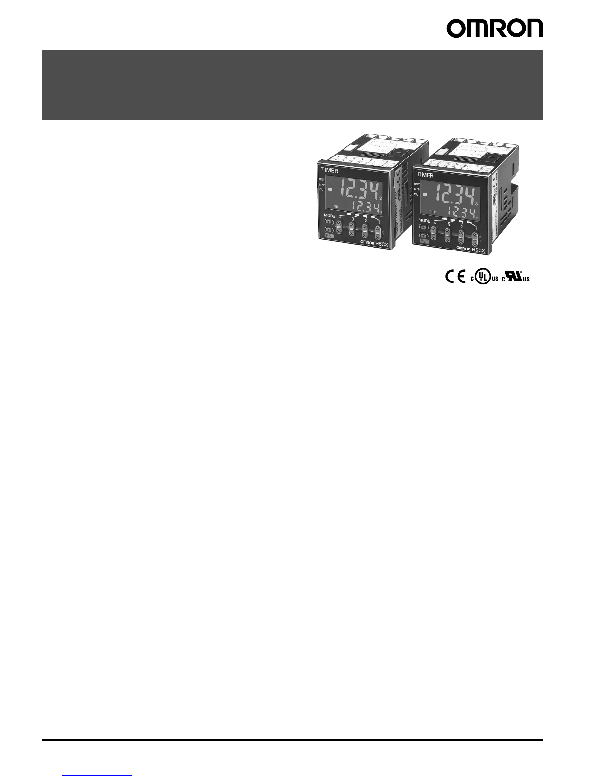
DIN 48 ´ 48-mm Multifunction Digital Timer/2-stage Digital Timer
• Highly visible display with backlit negative transmissive LCD.
• Finger-safe terminals (screw terminal block models).
• Complies with IP66, NEM A4, and UL Type 4X (when using the Y9 2S-29 W aterproof P acking and Y92F-30 F lush Mounting Adapter).
Contents
Multifunction Digital Timer
H5CX-A/-L........................................................ 2
2-stage Digital Timer
H5CX-B............................................................ 35
Common to All Models
Safety Precautions........................................... 47
Warranty and Application Considerations........ 52
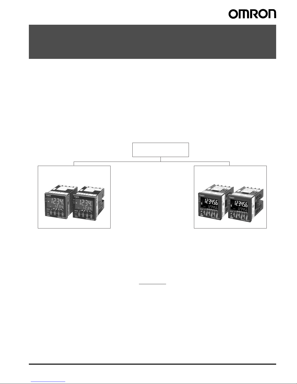
H5CX Series
H5CX-A/-L H5CX-B
Multifunction Digital Timer
with 4-digit display
H5CX-A (standard type)
H5CX-L (economy type)
2-stage Digital Timer
with 6-digit display
H5CX-B
1
2
Page 2
2 Multifunction Digital Timer H5CX-A/-L
Multifunction Digital Timer
H5CX-A/-L
DIN 48 ´ 48-mm Multifunction Digital Timer
with a Bright, Easy-to-view, Negative
Transmissive LCD.
• Programmable PV color to visually alert when output status
changes (screw terminal block models).
• Intuitive setting enabled using DIP switch (H5CX-A/-A11 models) and ergonomic up/down digit keys.
• Twin timer in one body to meet a broader range of cyclic contr ol
application requirements as well as ON/OFF duty adjustable
flicker mode.
• PNP/NPN switc hable DC-volta ge inp ut (H5 C X-A/-A11 mo de ls) .
• Meet a variety of mounting requirements:
Screw terminal block models, and pin-style terminal models.
• Six-language instruction manual.
Contents
Model Number Structure .................................................................3
Ordering Information.................. .....................................................3
Specifications..................................................................................4
Connections ....................................................................................7
Nomenclature..................................................................................11
Dimensions .....................................................................................12
Operating Procedures.....................................................................17
Setting Procedure Guide ..........................................................17
Operating Procedures (Timer Function) ...................................18
Operating Procedures (Twin Timer Function) ...........................26
Operation in Timer/Twin Timer Selection Mode........................31
Additional Information .....................................................................32
Page 3
Multifunction Digital Timer H5CX-A/-L 3
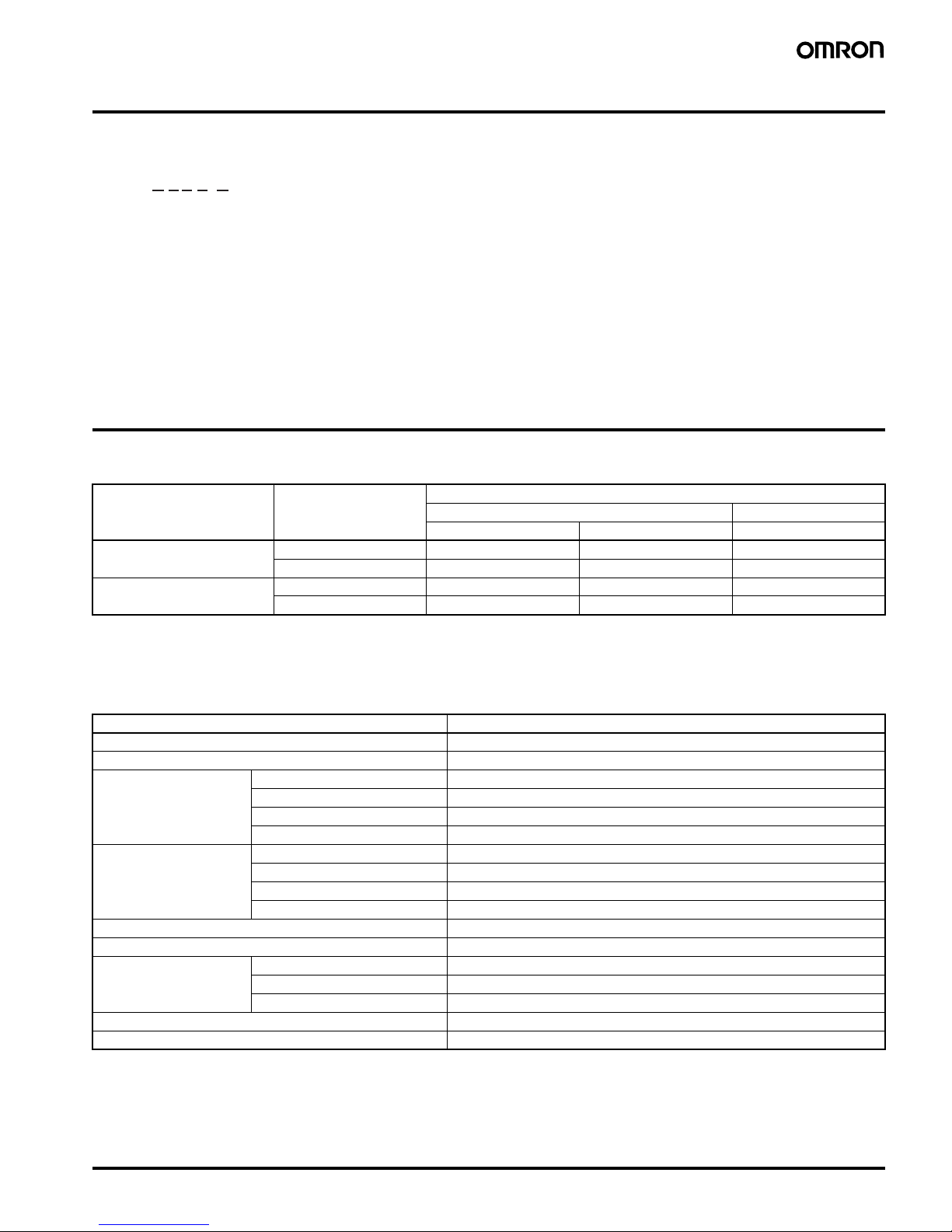
Model Number Structure
■Model Number Legend
1. Type classifier
A: Standard type
L: Economy type
2. External connection
None:S crew term inals
8: 8-pin socket
11: 11-pin socket
3. Output type
None:Contact output
S: Transistor output
4. Supply voltage
None:100 to 240 V AC 50/60 Hz
D: 12 to 24 VDC/24 VAC 50/60 Hz
5. Case color
None:Black
G: Light gray (Munsell 5Y7/1): Produced upon request.
Ordering Information
■List of Models
Note: Depending on the wiring, unwanted current from the AC power supply may occasionally burn out internal part s. H5CX-A/-L (except for
H5CX-A11/-A11S) models do not have a transformer. Therefore, the power supply and input circuit are not insulated. Refer to Safety Precautions (H5CX-A/-L) on page 49 for wiring details. The power supply and input circuit for H5CX-A11/-A11S models have basic insulation.
■Accessories (Order Separately)
Note 1. Supplied with H5CX-A@ models (except for H5CX-A11@ and H5CX-L8@ models).
2. Y92A-48G is a finger-safe terminal cover attached to the P3G-08 or P3GA-11 Socket.
1 2 3 4 5
H5CX-@@@@-@
Output type Supply voltage Models
Standard type Economy type
Screw terminals 11-pin socket 8-pin socket
Contact output 100 to 240 VAC H5CX-A H5CX-A11 H5CX-L8
12 to 24 VDC/24 VAC H5CX-AD H5CX-A11D H5CX-L8D
Transistor output 100 to 240 VAC H5CX-AS H5CX-A11S H5CX-L8S
12 to 24 VDC/24 VAC H5CX-ASD H5CX-A11SD H5CX-L8SD
Name Models
Flush Mounting Adapter (See note 1.) Y92F-30
Waterproof Packing (See note 1.) Y92S-29
Track Mounting/
Front Connecting Socket
8-pin P2CF-08
8-pin, finger-safe type P2CF-08-E
11-pin P2CF-11
11-pin, finger-safe type P2CF-11-E
Back Connecting Socket 8-pin P3G-08
8-pin, finger-safe type P3G-08 with Y92A-48G (See note 2.)
11-pin P3GA-11
11-pin, finger-safe type P3GA-11 with Y92A-48G (See note 2.)
Hard Cover Y92A-48
Soft Cover Y92A-48F1
Mounting Track 50 cm (l)
´ 7.3 mm (t) PFP-50N
1 m (l)
´ 7.3 mm (t) PFP-100N
1 m (l)
´ 16 mm (t) PFP-100N2
End Plate PFP-M
Spacer PFP-S
Page 4
4 Multifunction Digital Timer H5CX-A/-L
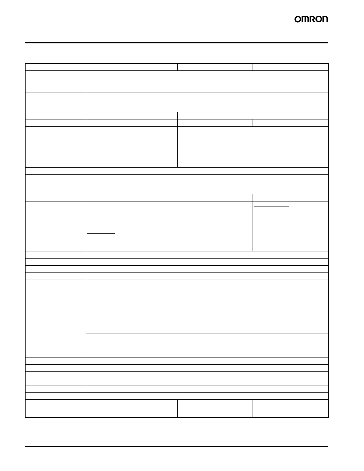
Specifications
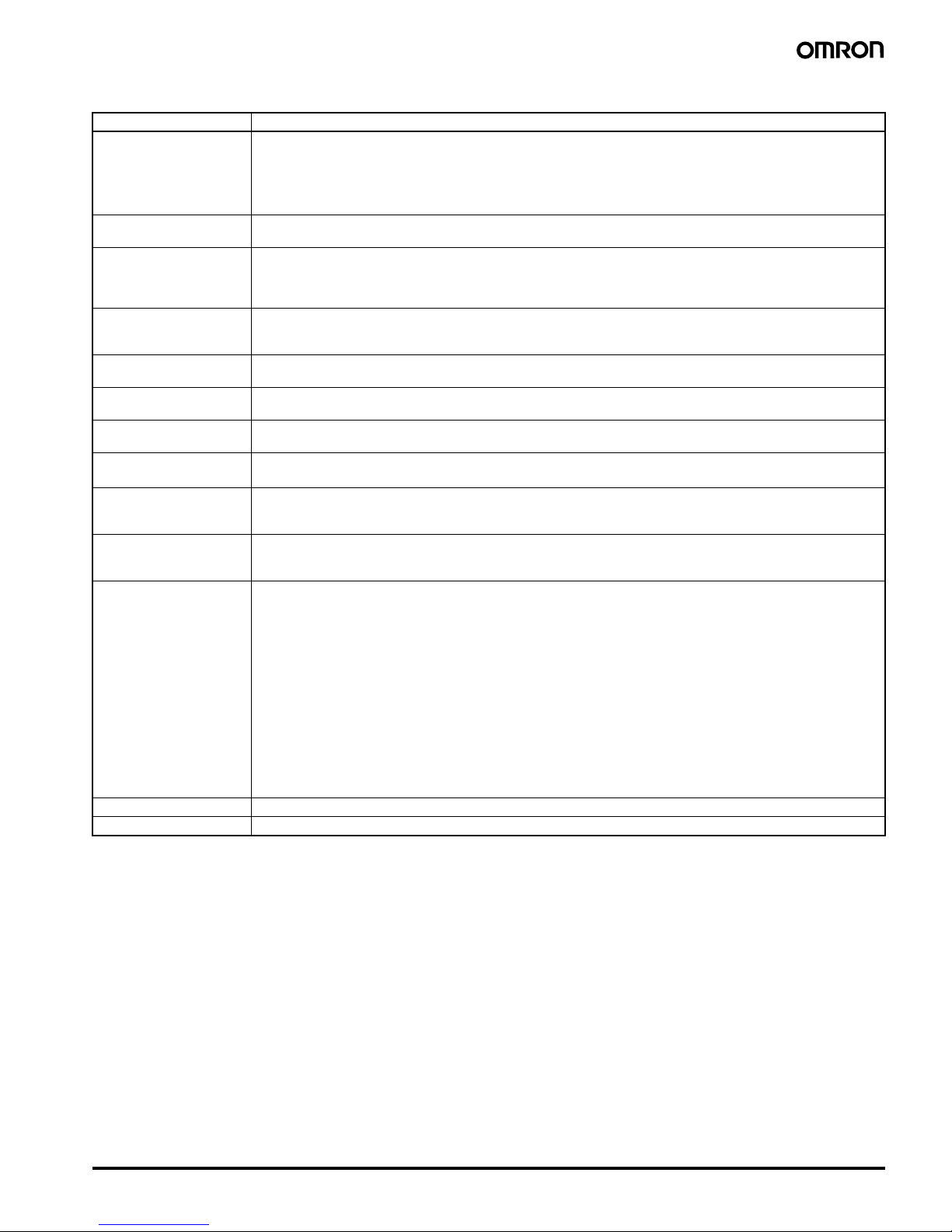
■Ratings
Note 1. Inrush current will flow for a short time when the power supply is turned ON. Refer to Inrush Current (Reference Values) on page 6.
2. The display is lit only when the power is ON.
Item H5CX-A@ H5CX-A11@ H5CX-L8@
Classification Digital timer
Rated supply voltage 100 to 240 VAC (50/60 Hz), 24 VAC (50/60 Hz)/12 to 24 VDC (permissible ripple: 20% (p-p) max.)
Operating voltage range 85% to 110% rated supply voltage (12 to 24 VDC: 90% to 110%)
Power consumption
(See note 1.)
Approx. 6.2 VA at 264 VAC
Approx. 5.1 VA at 26.4 VAC
Approx. 2.4 W at 12 VDC
Mounting method Flush mounting Flush mounting, surface mounting, DIN track mounting
External connections S crew terminals 11-pin socket 8-pin socket
Terminal screw tightening
torque
0.5 N·m max. ---
Display
(See note 2.)
7-segment, negative transmissive LCD;
Present value:
11.5-mm-high characters,
red or green (programmable)
Set value: 6-mm-high characters, green
7-segment, negative transmissive LCD
Present value:
11.5-mm-high characters, red
Set value: 6-mm-high characters, green
Digits 4 digits
Time ranges 9.999 s (0.001-s unit), 99.99 s (0.01-s unit), 999.9 s (0.1-s unit), 9999 s (1-s unit), 99 min 59 s (1-s unit)
999.9 min (0.1-min unit), 9999 min (1-min unit), 99 h 59 min (1-min unit), 999.9 h (0.1-h unit), 9999 h (1-h unit)
Timer mode Elapsed time (Up), remaining time (Down) (selectable)
Input signals Signal, reset, gate Signal, reset
Input method No-voltage input/voltage input (switchable)
No-voltage Input
ON impedance: 1 kW max. (Leakage current: 5 to 20 mA when 0 W)
ON residual voltage: 3 V max.
OFF impedance: 100 k
W min.
Voltage Input
High (logic) level: 4.5 to 30 VDC
Low (logic) level: 0 to 2 VDC
(Input resistance: approx. 4.7 k
W)
No-voltage Input
ON impedance: 1 kW max. (Leakage current: 5 to 20 mA when 0
W)
ON residual voltage: 3 V max.
OFF impedance: 100 k
W min.
Signal, reset, gate Minimum input signal width: 1 or 20 ms (selectable, same for all input)
Reset system Power resets (except for A-3, b-1, and F modes), external and manual reset
Power reset Minimum power-opening time: 0.5 s (except for A-3, b-1, and F mode)
Reset voltage 10% max. of rated supply voltage
Sensor waiting time 250 ms max. (Control output is turned OFF and no input is accepted during sensor waiting time.)
Output modes A, A-1, A-2, A-3, b, b-1, d, E, F, Z, ton or toff
One-shot output time 0.01 to 99.99 s
Control output SPDT contact output: 5 A at 250 VAC/30 VDC, resistive load (cos
f=1)
Minimum applied load: 10 mA at 5 VDC (failure level: P, reference value)
Transistor output: NPN open collector, 100 mA at 30 VDC max.
residual voltage: 1.5 VDC max. (Approx. 1 V)
Leakage current: 0.1 mA max.
Output category according to EN60947-5-1 for Timers with Contact Outputs (AC-15; 250 V 3 A/AC-13; 250 V 5 A/
DC-13; 30 V 0.5 A)
Output category according to EN60947-5-2 for Timers with Transistor Outputs (DC-13; 30 V 100 mA)
NEMA B300 Pilot Duty, 1/4 HP 5-A resistive load at 120 VAC, 1/3 HP 5-A resistive load at 240 VAC
Key protection Yes
Memory backup EEPROM (overwrites: 100,000 times min.) that can store data for 10 years min.
Ambient temperature Operating:
-10 to 55°C (-10 to 50°C if timers are mounted side by side) (with no icing or condensation)
Storage:
-25 to 65°C (with no icing or condensation)
Ambient humidity 25% to 85%
Case color B lack (N1.5)
Attachments Waterproof packing,
flush mounting adapter,
label for DIP switch settings
Label for DIP switch settings None
Page 5
Multifunction Digital Timer H5CX-A/-L 5
■Characteristics
Note 1. The values are based on the set value.
2. The value is applied for a minimum pulse width of 1 ms.
3. To meet UL listing requirements with H5CX-L8@/-A11@ models, an OMRON P2CF-08-@ or P3G-08 Socket must be mounted on the Timer.
Otherwise, H5CX-L8@/-A11@ models are considered to meet UL508 recognition requirements.
4. The Y92S-29 Waterproof Packing and Y92F-30 Flush Mounting Adapter are necessary to ensure IP66, NEMA4, and UL Type 4X waterproofing between the H5CX and installation panel.
Item H5CX-A@/-A11@/-L8@
Accuracy of operating time
and setting error (including
temperature and voltage influences) (See note 1.)
Power-ON start:
±0.01% ±50 ms max. Rated against set value
Signal start:
±0.005% ±30 ms max. Rated against set value
Signal start for transistor output model:
±0.005% ±3 ms max. (See note 2.)
If the set value is within the sensor waiting time at startup the control output of the H5CX will not turn ON until the
sensor waiting time passes.
Insulation resistance 100 M
W min. (at 500 VDC) between current-carrying terminal and exposed non-current-carrying metal parts, and
between non-continuous contacts
Dielectric strength 2,000 VAC , 50/60 Hz for 1 min between current-carr ying metal parts and non-current-carrying metal par ts
1,000 VA C (f or H5CX-@SD), 50/60 Hz for 1 min between control output, power supply, and input circuit (2,000 VAC
for models other than H5CX-@SD)
1,000 VAC, 50/60 Hz for 1 min between non-continuous contacts
Impulse withstand voltage 3 kV (between power terminals) for 100 to 240 VAC, 1 kV for 24 VAC/12 to 24 VDC
4.5 kV (between current-carrying terminal and exposed non-current-carrying metal parts) for 100 to 240 VAC
1.5 kV for 24 VA C/12 to 24 VDC
Noise immunity
±1.5 kV (between power terminals) and ±600 V (between input terminals), square-wave noise by noise simulator
(pulse width: 100 ns/1
ms, 1-ns rise)
Static immunity Destruction: 15 kV
Malfunction: 8 kV
Vibration resistance Destruction: 10 to 55 Hz with 0.75-mm single amplitude each in three directions, four cycles each (8 min per cycle)
Malfunction: 10 to 55 Hz with 0.35-mm single amplitude each in three directions, four cycles each (8 min per cycle)
Shock resistance
Destruction: 294 m/s
2
each in three directions
Malfunction: 98 m/s
2
each in three directions
Life expectancy Mechanical: 10,000,000 operations min. (under no load at 18,000 operations/h)
Electrical: 100,000 operations min. (5 A at 250 VAC, resistive load at 1,800 operations/h)
See Life-test Curve on page 6.
Approved safety standards
(See notes 3 and 4.)
UL508/Listing, UL50 T ype 4X for indoor use (enclosure rating), CSA C22.2 No. 14, conforms to EN61812-1 (Pollution
degree 2/overvoltage category III)
Conforms to VDE0106/P100 (finger protection).
EMC (EMI) EN61812-1
Emission Enclosure: EN55011 Group 1 class A
Emission AC mains: EN55011 Group 1 class A
(EMS) EN61812-1
Immunity ESD: EN61000-4-2: 6 kV contact discharge (level 2)
8 kV air discharge (level 3)
Immunity RF-interference: EN61000-4-3: 10 V/m (Amplitude-modulated, 80 MHz to 1 GHz) (level 3);
10 V/m (Pulse-modulated, 900 MHz
±5 MHz) (level 3)
Immunity Conducted
Disturbance: EN61000-4-6: 10 V (0.15 to 80 MHz) (level 3)
Immunity Burst: EN61000-4-4: 2 kV power-line (level 3);
1 kV I/O signal-line (level 4)
Immunity Surge: EN61000-4-5: 1 kV line to lines (power and output lines) (level 3);
2 kV line to ground (power and output lines) (level 3)
Immunity Voltage Dip/Interruption EN61000-4-11: 0.5 cycle, 100% (rated voltage)
Degree of protection Panel surface: IP66 and NEMA4 (indoors), and UL Type 4X (indoors) (See note 4.)
Weight H5CX-A@: Approx. 135 g, H5CX-A11@/-L8@: Approx. 105 g
Page 6
6 Multifunction Digital Timer H5CX-A/-L
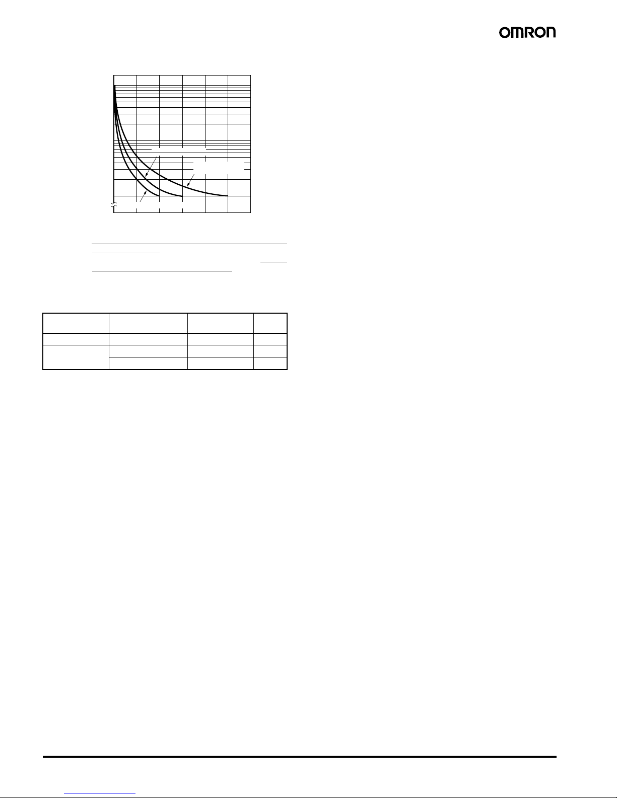
■Life-test Curve (Reference Values)
Reference: A maximum current of 0.15 A can be switched at
125 VDC (cosf=1) and a maximum current of 0.1 A
can be switched if L/R is 7 ms. In both cases, a life of
100,000 operations can be expected. The minimum
applicable load is 10 mA at 5 VDC (failure level: P).
■Inrush Current (Reference Values)
1,000
500
100
50
10
0
12345
Switching operations (× 10
4
)
30 VDC L/R=7 ms
250 VAC cosφ=0.4
250 VDC/30 VDC
cosφ=1
Load curren t (A)
V oltage Applied voltage Inrush current
(peak value)
Time
100 to 240 VAC 264 VAC 5.3 A 0.4 ms
24 VAC/
12 to 24 VDC
26.4 VAC 6.4 A 1.4 ms
26.4 VDC 4.4 A 1.7 ms
Page 7
Multifunction Digital Timer H5CX-A/-L 7
Connections
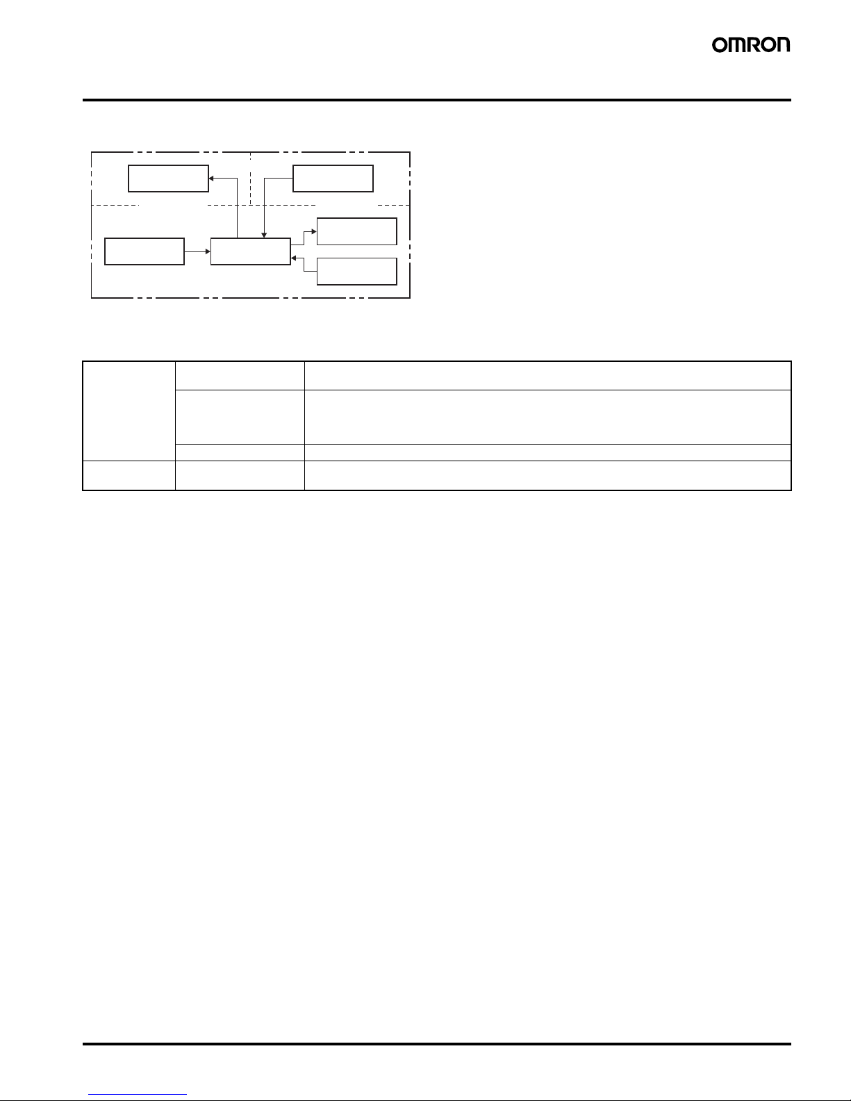
■Block Diagram
Note: Power circuit is not insulated from the input circuit, except for H5CX-A11/-A11S, which have basic insulation.
■I/O Functions
Output circuit
Input circuit
Internal control
circuit
Power supply
circuit
Display circuit
Key switch
circuit
(See note.)
(Basic insulation)
(Basic insulation)
Inputs Start signal Stops timing in A-2 and A-3 (power ON delay) modes.
Starts timing in other modes.
Reset Resets present value. (In elapsed time mode, the present value returns to 0; in remaining time
mode, the present value returns to the set value.)
Count inputs are not accepted and control output turns OFF while reset input is ON.
Reset indicator is lit while reset input is ON.
Gate Inhibits timer operation.
Outputs Control output (OUT) O utputs take place according to designated operating mode when timer reaches corresponding set
value.
Page 8
8 Multifunction Digital Timer H5CX-A/-L
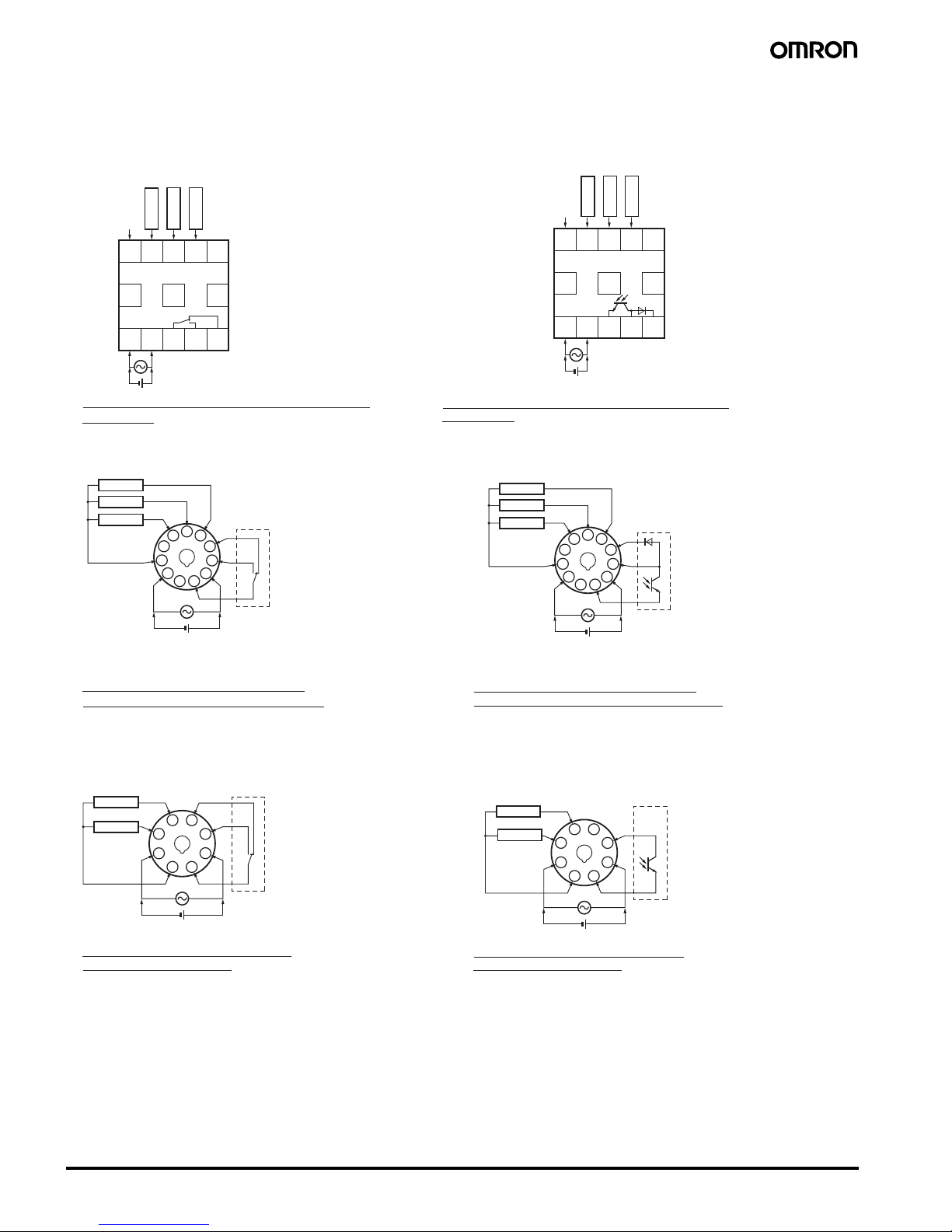
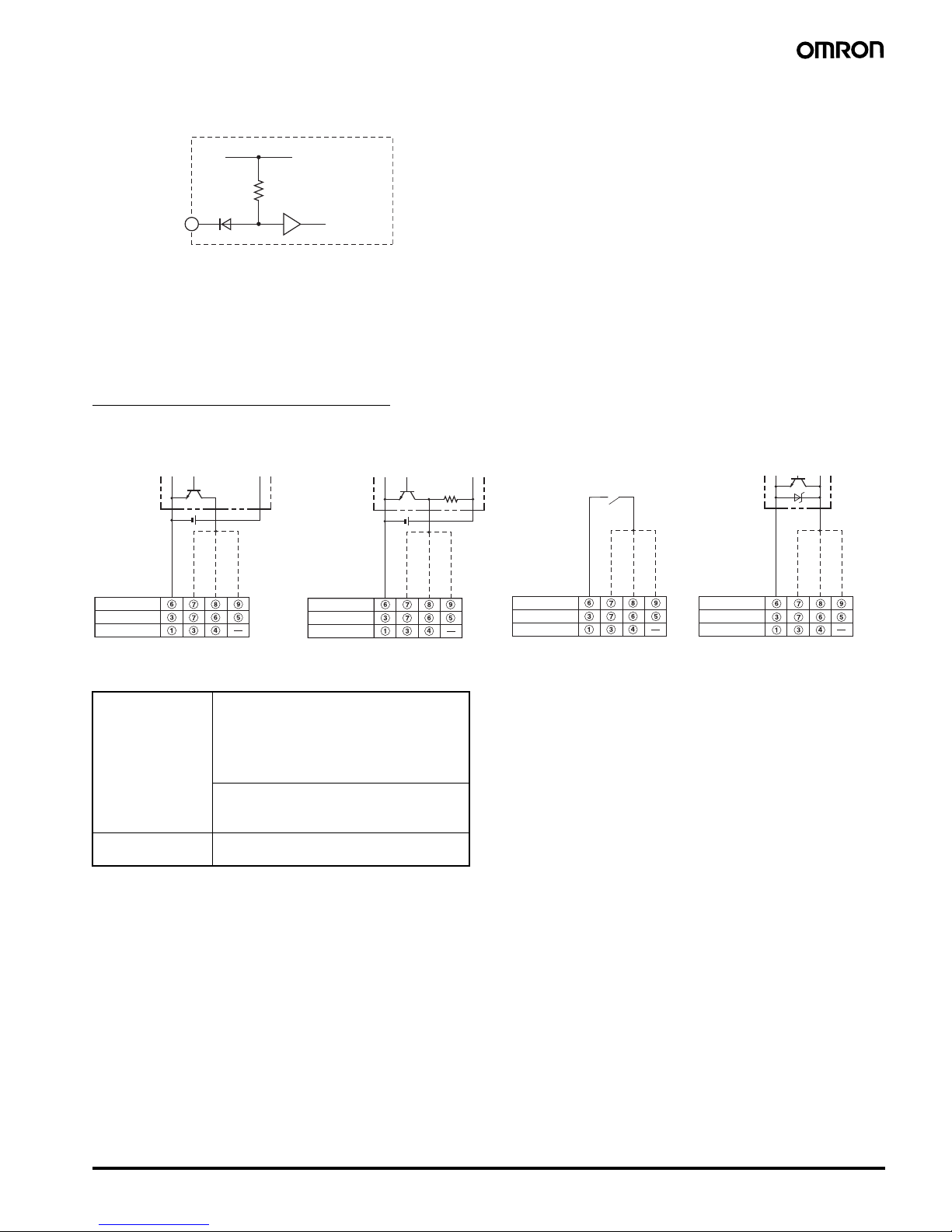
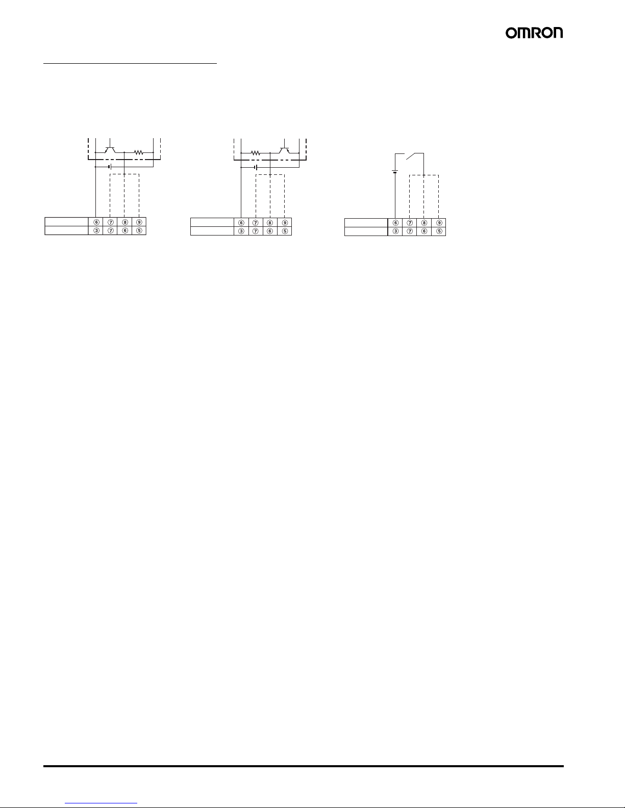
■Terminal Arrangement
Confirm that the power supply meets specifications before use.
Note 1. Do not connect unused terminals as relay terminals.
2. The power supply and input circuit are not insulated, so unwanted current from the AC power supply may burn out internal parts. Refer to
Safety Precautions (H5CX-A/-L) on page 49 for wiring details.
6
7
8
9
10
11
1
2
3
4
5
(+)(−)
0 V
6
7
8
9
10
11
1
2
3
4
5
(+)(−)
0 V
4
3
2
1 8
7
6
5
(+)(−)
0 V
4
3
2
1 8
7
6
5
(+)(−)
0 V
678910
11 12 13
(+)(−)
1234
5
678910
11 12 13
(+)(−)
1234
5
H5CX-A/-AD
H5CX-AS/-ASD
Reset
Signal
Gate
Unused
Input use 0 V
Unused
Unused
Unused
Contact output
H5CX-A11/-A11D
H5CX-A11S/-A11SD
Unused
Internal circuit
H5CX-L8/-L8D
H5CX-L8S/-L8SD
Gate
Signal
Reset
Unused
Internal circuit
Gate
Signal
Reset
Unused
Unused
Internal circuit
Signal
Reset
Internal circuit
Signal
Reset
Unused
Transistor output
Reset
Signal
Gate
Unused
Input use 0 V
Unused
Unused
Unused
Contact output
Transistor output
The power supply and input circuit are not insulated.
(See note 2.)
Terminals 1 and 6 of the H5CX-AD are connected internally.
The power supply and input circuit are not insulated.
(See note 2.)
Terminals 1 and 6 of the H5CX-ASD are connected internally.
The power supply and input circuit of the
H5CX-A11 have basic insulation.
The power supply and input circuit of the
H5CX-A11D are not insulated. (See note 2.)
Terminals 2 and 3 of the H5CX-A11D are
connected internally.
The power supply and input circuit of the
H5CX-A11S have basic insulation.
The power supply and input circuit of the
H5CX-A11SD are not insulated. (See note 2.)
Terminals 2 and 3 of the H5CX-A11SD are
connected internally.
The power supply and input circuit are
not insulated. (See note 2.)
Terminals 1 and 2 of the H5CX-L8D are
connected internally.
The power supply and input circuit are
not insulated. (See note 2.)
Terminals 1 and 2 of the H5CX-L8SD
are connected internally.
Contact output
Transistor output
Page 9
Multifunction Digital Timer H5CX-A/-L 9
■Input Circuits
Note: When using no-voltage input (NPN input).
■Input Connections
The inputs of the H5CX-A@/-A11@ are no-voltage (short-circuit or open) inputs or voltage inputs.
The input of the H5CX-L8@ is no-voltage input only.
Note: Po wer circuit is not insulated from the input circuit, except f or H5CX-A11/-A11S, which hav e basic insulation. For wiring, refer to Safety Pre-
cautions (H5CX-A/-L) on page 49.
No-voltage Inputs (NPN Inputs)
No-voltage Input Signal Levels
Note: The DC voltage must be 30 VDC max.
Applicable Two-wire Sensor
Leakage current: 1.5 mA max.
Switching capacity: 5 mA min.
Residual voltage: 3.0 VDC max.
Operating voltage: 10 VDC
+14 V
1 kΩ
Signal, Reset, and Gate Input
Internal circuit
IN
0 V
0 V
0 V
PC or sensor
Input
H5CX-A
@
H5CX-A11
@
Signal input
Gate input
Reset input
Contact Input
H5CX-L8@
Open Collector
Operate with transistor ON Operate with transistor ON
Operate with relay ON
Voltage Output
(Connection to a voltage output
sensor)
Sensor
H5CX-A
@
H5CX-A11
@
Signal input
Gate input
Reset input
H5CX-L8@
H5CX-A
@
H5CX-A11
@
H5CX-L8@
Input
Signal input
Gate input
Reset input
Input
(Connection to NPN open
collector output sensor)
0 V
Operate with transistor ON
H5CX-A
@
H5CX-A11
@
Signal input
Gate input
Reset input
H5CX-L8@
Input
DC T wo-wire Sensor
No-contact input Short-circuit level
Transistor ON
Residual voltage: 3 V max.
Impedance when ON: 1 k
W max.
(the leakage current is 5 to 20 mA when the
impedance is 0
W)
Open level
Transistor OFF
Impedance when OFF: 100 k
W min.
Contact input Use contact which can adequately switch
5 mA at 10 V
Page 10
10 Multifunction Digital Timer H5CX-A/-L
Voltage Inputs (PNP Inputs)
Voltage Input Signal Levels
High level (Input ON): 4.5 to 30 VDC
Low level (Input OFF): 0 to 2 VDC
Input resistance: Approx. 4.7 k
W
Note: The DC voltage must be 30 VDC max.
0 V
0 V 0 V
Contact Input
No-contact Input
(NPN T ransistor)
Operate with transistor OFF
Operate with transistor ON
Operate with relay ON
No-contact Input
(PNP T ransistor)
Signal input
Gate input
Reset input
Input
H5CX-A
@
H5CX-A11
@
Sensor
Sensor
Signal input
Gate input
Reset input
Input
H5CX-A
@
H5CX-A11
@
Signal input
Gate input
Reset input
Input
H5CX-A
@
H5CX-A11
@
(Connection to NPN open
collector output sensor)
(Connection to PNP open
collector output sensor)
Page 11
Multifunction Digital Timer H5CX-A/-L 11
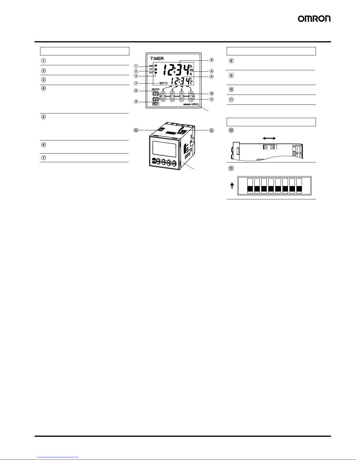
Nomenclature
Front color: Black
Indicator
Reset Indicator (orange)
Key Protection Indicator (orange)
Control Output Indicator (orange)
Present Value
(red or green (programmable) for
H5CX-A models, red for H5CX-A11
/-L models)
Character height: 11.5 mm
Time Unit Display
(Color is same as present value.):
(If the time range is 0 min, 0 h, 0.0 h,
or 0 h 0 min, this display flashes to
indicate timing operation.)
Set Value (green)
Character height: 6 mm
Set Value 1, 2 Display
Front View
Case color: Black
Operation Key
Mode Key
(Changes modes and setting items)
Reset Key
(Resets present value and output)
Up Keys 1 to 4
Down Keys 1 to 4
Switches
Key-protect Switch
DIP Switch
(Default setting) OFF ON
12345678
OFF
ON
Note 1: All the pins are factory-set to OFF.
2: There is no DIP switch on the H5CX-L8@.
Page 12
12 Multifunction Digital Timer H5CX-A/-L
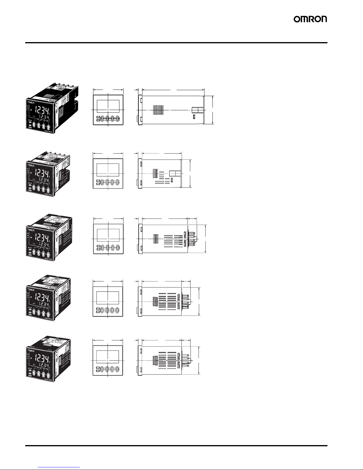
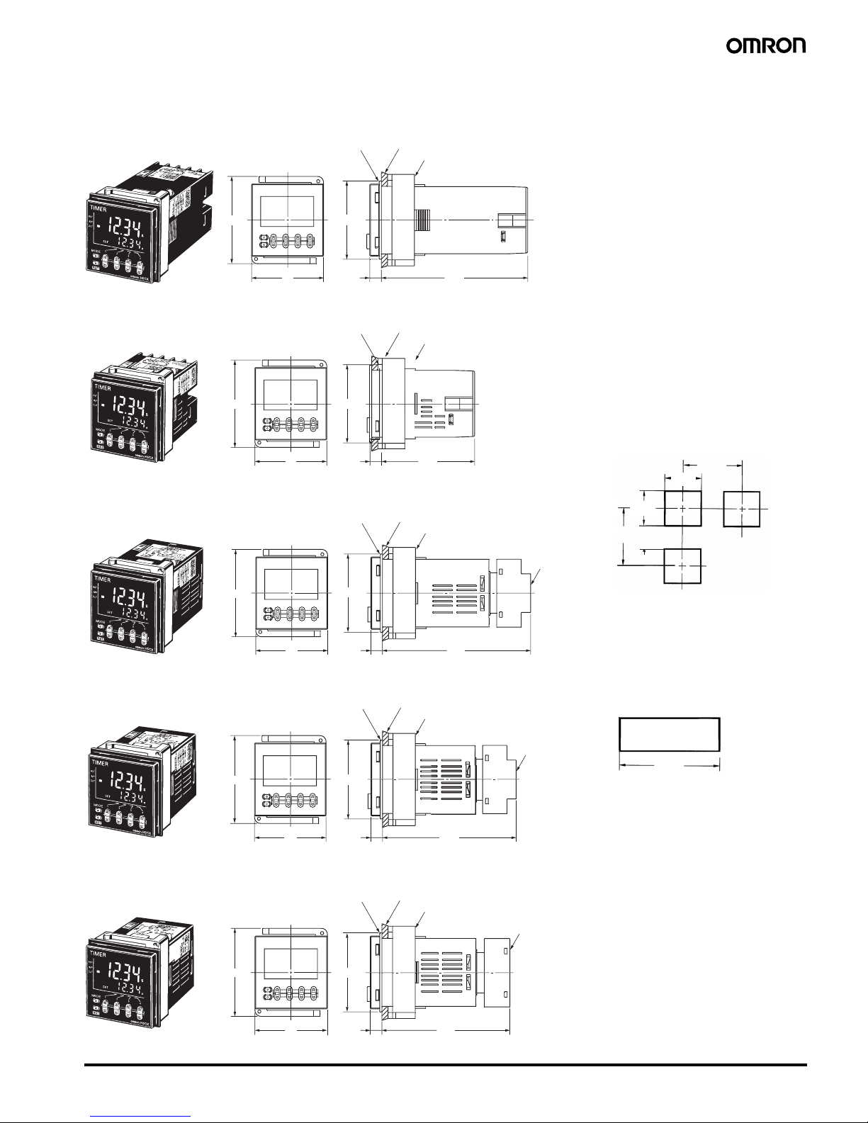
Dimensions
Note: All units are in millimeters unless otherwise indicated.
■Dimensions without Flush Mounting Adapter
H5CX-A/-AS (Flush Mounting Models)
H5CX-AD/-ASD (Flush Mounting Models)
H5CX-A11/-A11S (Flush Mounting/Surface Mounting Models)
H5CX-A11D/-A11SD (Flush Mounting/Surface Mounting Models)
H5CX-L8@ (Flush Mounting/Surface Mounting Models)
44.8x44.8
100
6
48x48
Note: M3.5 terminal screw (effective length: 6 mm)
44.8x44.
8
64
648x48
Note: M3.5 terminal screw (effective length: 6 mm)
44.8x44.
8
72.
5
6
48x4
8
H
5
C
X
-
A
1
1
D
63.7
6
44.8
x44.
8
48x48
44.8
x44.
8
63.7
14.
3
6
48x48
Page 13
Multifunction Digital Timer H5CX-A/-L 13
■Dimensions wit h Flush Mounting Adapter
H5CX-A/-AS (Provided with Adapter and Waterproof Packing)
H5CX-AD/-ASD (Provided with Adapter and Waterproof Packing)
H5CX-L8@ (Adapter and Waterproof Packing Ordered Separately)
58
4
8
98.57.5
(51)
Pan
el
Y92S-29 (provided
)
Waterproof Packin
g
Y92F-30 (provided)
Flush Mountin
g
Adapte
r
58
4
8
7.
5
(51)
62.5
58
4
8
7.
5
(51)
98.
7
A
45
+0.6
−0
45
+0.6
−0
+1
0
A = {48n−2.5 + (n−1) x 4}
+1
0
A = (51n−5.5)
+1
0
A = (48n − 2.5)
58
4
87.5
(51)
89.9
Pan
el
H5CX-A11/-A11S (Adapter and Waterproof Packing Ordered Separately
)
Pan
el
Panel Cutouts
60 min.
60 min.
With Y92A-48F1 attached.
With Y92A-48 attached.
15 min.
n side by side mounting
H5CX-A11D/-A11SD (Adapter and Waterproof Packing Ordered Separately
)
Pane
l
Y92S-29 (provided
)
Waterproof Packin
g
Y92F-30 (provided
)
Flush Mounting Adapte
r
Y92S-29 (order separately)
Waterproof Packin
g
Y92F-30 (order separately)
Flush Mounting Adapter
P3GA-11
(order separatel
y
)
Rear Surface
C
onnection
S
ocke
t
Y92S-29 (order separately)
Waterproof Packin
g
Y92F-30 (order separately)
Flush Mounting Adapte
r
P3GA-11
(order separately)
Rear Surface
C
onnection
S
ocke
t
Note 1. The mounting panel thickness
should be 1 to 5 mm.
2. To allow easier operability, it is
recommended that Adapters are
mounted so that the gap between
sides with hooks is at least 15 mm.
3. It is possible to mount timers side
by side, but only in the direction
without the hooks.
Panel cutouts areas
shown below.
(according to DIN43700).
58
4
8
7.
5
(51)
84.8
Pan
el
Y92S-29 (order separately)
Waterproof Packin
g)
Y92F-30 (order separately)
Flush M
ounting Adapte
r
P3GA-11
(order separately)
Rear Surface
C
onnection
S
ocke
t
Page 14
14 Multifunction Digital Timer H5CX-A/-L
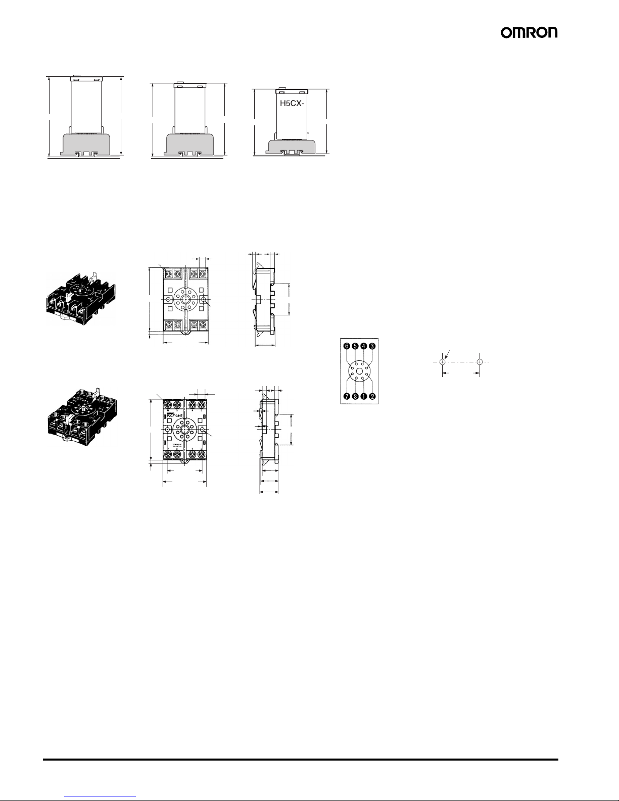
■Dimensions with Front Connecting Socket
Note: These dimensions vary with the kind of DIN track (reference value).
■Accessories (Order Separately)
Note: All units are in millimeters unless otherwise indicated.
109.7
1
03.2
100.
9
92.3
90
P2CF-11
-
@
P2CF-11
-
@
P2CF-
08-
H5CX
-
A11
/-
A11
S
H5CXA11D
/-
A11
SD
L
8
20.3 max.
7.8
3
4.5
35.4
4
40±0.2
40±0.2
7.8
4
35.4
20.3
19
3
1.3
5
4.5
70 max.
50 max.
20.3 max.
Track Mounting/Front Connecting Socket
P2CF-08
P2CF-08-E (Finger Safe Terminal Type)
Conforming to VDE0106/P100
Surface Mounting Holes
Two, 4.5 dia. or two, M4
50 max.
70 max.
21.5 max.
Terminal Arrangement/
Internal Connections
(Top Vie w)
Eight,
M3.5 x 7.5 sems
Two, 4.5 dia.
holes
Eight,
M3.5 x 7.5 sems
Two, 4.5 dia.
holes
Page 15
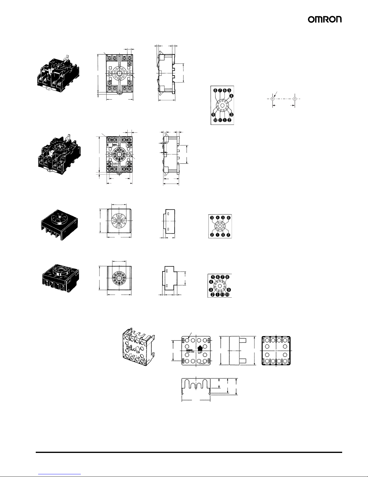
Multifunction Digital Timer H5CX-A/-L 15
40±0.2
7.8
3
4.5
35.4
4
7.8
4
40±0.2
35.4
30
5
4.5
3
1.2
Track Mounting/Front Connecting Socket
P2CF-11
Surface Mounting Holes
Two, 4.5 dia. or two, M4
70 max.
50 max.
31.2 max.
P2CF-11-E (Finger Safe Terminal Type)
Conforming to VDE0106/P100
70 max.
50 max.
31.2 max.
Terminal Arrangement/
Internal Connections
(Top Vie w)
Eleven,
M3.5 x 7.5 sems
Two, 4.5 dia.
holes
Eleven,
M3.5 x 7.5 sems
Two, 4.5 dia.
holes
45
45
4.9
17
45
45
25.6
4.5
16.3
6.2
34
47.7 x 47.7
48 x 48
47.4
16.5
24.6
27.6
27 dia.
Back Connecting Socket
P3G-08
P3GA-11
27 dia.
Finger Safe Terminal Cover
Conforming to VDE0106/P100
Y92A-48G
Twelve, 6.4 dia. holes
Terminal Arrangement/
Internal Connections
(Bottom View)
Terminal Arrangement/
Internal Connections
(Bottom View)
(Attachment for P3G-08/P3GA-11
Socket)
Page 16
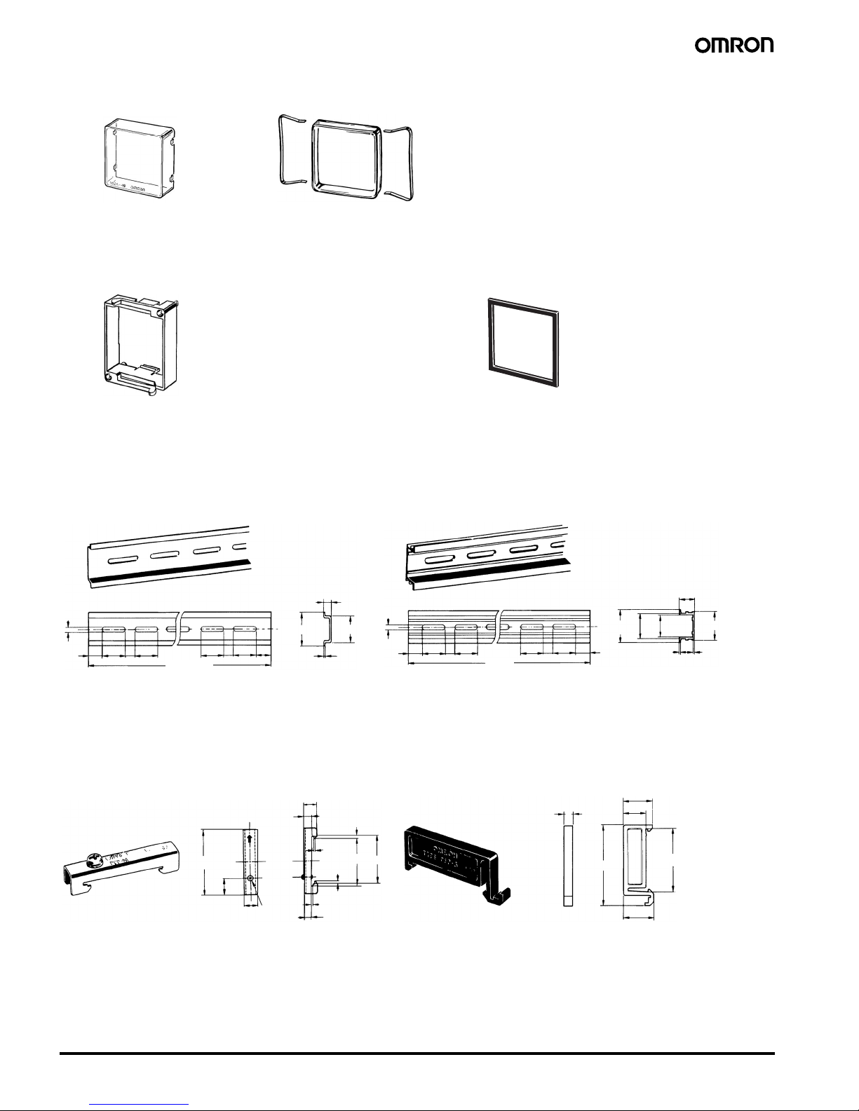
16 Multifunction Digital Timer H5CX-A/-L
Note: 1. Depending on the operating environment, the condition of
resin products may deteriorate, and may shrink or become
harder. Therefore, it is recommended that resin products
are replaced regularly.
2. The H5CX’s panel surface is water-resistive (conforming to
IP66) and so even if drops of water penetrate the gaps between the keys, there will be no adverse effect on internal
circuits. If, howev er, there is a possibility of oil being present
on the operator’s hands, use the Soft Cover. The Soft Cover
ensures protection equivalent to IP54F against oil. Do not,
however, use the H5CX in locations where it would come in
direct contact with oil.
Note: Order the Flush Mounting Adapter separately if it is lost or dam-
aged.
Note: Use Waterproof Packing to provide a level of water protection
that complies with NEMA4, UL T ype 4X, or IP66 standards. Order the Waterproof Packing separately if it is lost or damaged.
Depending on the operating environment, the Waterproof
Packing may deteriorate, contract, or harden and so regular replacement is recommended.
Hard Cover
Y92A-48
Soft Cover
Y92A-48F1
Y92F-30
Flush Mounting Adapter
(provided with H5CX-A@ models)
Waterproof Packing
(provided with H5CX-A@ models)
Y92S-29
4.5
15 25 25
25
25
*
10
10
7.3±0.15
35±0.3
27±0.15
1
4.5
15 25 25
25 25
15
10 10
1,000
27
24
16
29.2
1
1.5
50
11.5
10
6.2
1.8
1
35.5 35.3
1.8
1.3
4.8
5
16
12
44.3
16.5
10
34.8
35±0.3
Mounting T rack
PFP-100N, PFP-50N
PFP-100N2
End Plate
PFP-M
Spacer
PFP-S
1,000 (500)
(See note.)
Note: The values shown in parentheses are for the PFP-50N.
M4 x 8
pan head
screw
Page 17

Multifunction Digital Timer H5CX-A/-L 17
Operating Procedures
■Setting Procedure Gu id e
Settings for Timer Operation
Use the following settings for all models except the H5CX-L8@.
Refer to page 19 for the H5CX-L8@.
Note: At the time of delivery, the H5CX is set for timer operation.
Settings for Twin Timer Operation
Use the following settings for all models except the H5CX-L8@.
Refer to page 27 for the H5CX-L8@.
Note: At the time of delivery, the H5CX is set for timer operation.
12 345 678
ON
OFF
When Using Basic Functions Only
• Time range (0.001 s to 999.9 h,
except 9999 h and 9999min)
• Output mode (A, A-2, E, F)
• Timer mode (UP/DOWN)
• Input signal width (20 ms/1 ms)
When Using Other Time Ranges
(9999 h, 9999 min) and Output
Modes (A-1, A-3, b, b-1, d, and Z)
The settings can be performed easily with the DIP switch.
➡For details on the setting methods, refer to page 18.
All the functions can be set with the operation keys.
➡For details on the setting methods, refer to page 19.
When Using More Detailed Setting Items
(Output Time, NPN/PNP Input Mode,
Display Color, Key Protect Level)
Setting for items other than the basic functions can be
performed with the operation keys.
➡For details on the setting methods, refer to page 19.
Basic Functions
12 345 678
ON
OFF
When Using Basic Functions Only
• Time range (0.01 s to 99 min 59 s)
• ON/OFF start mode
(flicker OFF start/flicker ON start)
• Timer mode (UP/DOWN)
• Input signal width (20 ms/1 ms)
When Using Other Time Ranges
(999.9 min, 9999 min, 99 h 59 min,
999.9 h, 9999 h, 9.999 s)
The settings can be performed easily with the DIP switch.
➡For details on the setting methods, refer to page 26.
All the functions can be set with the operation keys.
➡For details on the setting methods, refer to page 27.
When Using More Detailed Setting Items
(NPN/PNP Input Mode, Display Color, Key
Protect Level)
Setting for items other than the basic functions can be
performed with the operation keys.
➡For details on the setting methods, refer to page 27.
Basic Functions
Page 18

18 Multifunction Digital Timer H5CX-A/-L (Timer Function)
■Operating Procedures (Timer Function)
Settings for Basic Functions
Note: All the pins are factory-set to OFF.
Note 1. Be sure to set pin 1 of the DIP switch to ON. If it is set to OFF, the DIP switch settings will not be enabled.
2. Changes to DIP switch settings are enabled when the power is turned ON. (Perform DIP switch settings while the power is OFF.)
3. There is no DIP switch on the H5CX-L8@. For details on the setting methods, refer to page 19.
4. When using time ranges or output modes that cannot be set with the DIP switch, all of the settings have to be made using the operation
keys. For details on the setting methods, refer to page 19.
12345678
OFF
ON
Settings for basic functions can be performed with just the DIP switch.
Be sure to set pin 1 to ON when using the DIP switch.
Item OFF ON
1 DIP switch set-
tings enable/
disable
Disabled Enabled
2 Time range Refer to the table on the right.
3
4
5 Output mode Refer to the table on the right.
6
7 Timer mode Elapsed time
(UP)
Remaining time
(DOWN)
8 Input signal
width
20 ms 1 ms
Easy Confirmation of Switch Settings Using Indicators
The ON/OFF status of the DIP switch pins can be
confirmed using the front display. For details, refer to page 31.
Pin 2 Pin 3 Pin 4 Time range
ON ON ON 0.001 s to 9.999 s
OFF OFF OFF 0.01 s to 99.99 s
ON OFF OFF 0.1 s to 999.9 s
OFF ON OFF 1 s to 9999 s
ON ON OFF 0 min 01 s to 99 min
59 s
OFF OFF ON 0.1 min to
999.9 min
ON OFF ON 0 h 01 min to
99 h 59 min
OFF ON ON 0.1 h to 999.9 h
Pin 5 Pin 6 Output mode
OFF OFF A mode (signal ON delay
(I): power reset operation)
ON OFF A-2 mode: (power ON de-
lay (I): power reset operation)
OFF ON E mode (interval: power
reset operation)
ON ON F mode (accumulative:
power hold operation)
Detailed Settings
After making DIP switch settings for basic functions, detailed settings (see note) can be added using the operation keys.
For details, refer to page 19.
Note: Output time, NPN/PNP input mode, display color, key protect level.
Page 19

Multifunction Digital Timer H5CX-A/-L (Timer Function) 19
Settings for Advanced Functions
ss hs
(1 ms)(20 ms)
(A-1) (A-2) (A-3) (b-1)(b) (d) (E) (F) (Z)(A)
(KP-2) (KP-3) (KP-4) (KP-5)(KP-1)
......
s
Settings that cannot be performed with the DIP switch are performed with the operation keys.
Display color
(NPN input) (PNP input)
Only displayed for H5CX-A@ and H5CX-A11@ models.
(Red) (Green) Red-green Green-red
Displayed for terminal-block models (H5CX-A@) only.
Power ON
Run mode
See note 1. See note 2.
3 s min. 3 s min.
For details on operations in run mode, refer to page 21.
Note 1. If the mode is switched to the function setting mode during operation,
operation will continue.
2. Changes made to settings in function setting mode are enabled for the
first time when the mode is changed to run mode. Also, when settings
are changed, the timer is reset (time initialized and output turned OFF).
The characters displayed in reverse video are the default settings.
When performing settings with operation keys only, set pin1 of the
DIP switch to OFF (factory setting). If pin 1 of the DIP switch is set
to ON, the setting items indicated in will not be displayed.
For details, refer to Time Range List below.
Time range
Timer mode
(Elapsed
time)
(Remaining
time)
Output mode
Function setting mode
Output time
: Output hold/0.01 to 99.99 s
Display Set V alue
Time Range List
Input
signal
NPN/PNP
input
Key protect
level
0.1 s to 999.9 s
1 s to 9999 s
0 min 01 s to 99 min 59 s
0.1 min to 999.9 min
1 min to 9999 min
0 h 01 min to 99 h 59 min
0.1 h to 999.9 h
1 h to 9999 h
0.001 s to 9.999 s
0.01 s to 99.99 s
(default setting)
Set the time range using the keys.
Set the timer mode using the keys.
Set the output mode using the keys.
Set each digit for the output time using the corresponding keys.
(If the output time is set to 0.00, is displayed.)
Displayed for modes A, A-1, A-2, A-3, b, and b-1 only.
Set the input signal width using the keys.
Set the NPN/PNP input mode using the keys.
Set the display color using the keys.
Set the key protect level using the keys.
Page 20

20 Multifunction Digital Timer H5CX-A/-L (Timer Function)
Explanation of Functions
Time Range (timr) (Setting possible using DIP switch.)
Set the range to be timed in the range 0.000 s to 9,999 h. Settings of
type ---- h (9,999 h) and ---- min (9, 999 min) cannot, however, be
made with the DIP switch. Use the operation keys if these settings
are required.
Timer Mode (timm) (Setting possible using DIP switch.)
Set either the elapsed time (UP) or remaining time (DOWN) mode.
Output Mode (outm) (Setting possible using DIP switch.)
Set the output mode. The possible settings are A, A-1, A-2, A-3, b, b1, d, E, F, and Z. Only output modes A, A-2, E, and F can be set
using the DIP switch. Use the operation keys if a different setting is
required. (For details on output mode operation, refer to “Timing
Charts” on page 22.)
Output Time (otim)
When using one-shot output, set the output time for one-shot output
(0.01 to 99.99 s). One-shot output can be used only if the selected
output mode is A, A-1, A-2, b, or b-1. If the output time is set to 0.00,
hold is displayed, and the output is held.
Input Signal Width (iflt) (Setting possible using DIP
switch.)
Set the minimum signal input width (20 ms or 1 ms) for signal, reset,
and gate inputs. The same setting is used for all external inputs (signal, reset, and gate inputs). If contacts are used for the input signal,
set the input signal width to 20 ms. Processing to eliminate chattering is performed for this setting.
NPN/PNP Input Mode (imod)
Select either NPN input (no-voltage input) or PNP input (voltage
input) as the input format. The same setting is used for all external
inputs. For details on input connections, refer to “Input Connections”
on page 9.
Display Color (colr)
Set the color used for the present value.
Key Protect Level (kypt)
Set the key protect level.
When the key-protect switch is set to ON, it is possible to prevent setting errors by prohibiting the use of certain operation keys by specifying the
key protect level (KP-1 to KP-5). The key protect indicator is lit while the key-protect switch is set to ON.
Note: Changing mode to timer/twin timer selection mode ( + 1 s min.) or function setting mode ( 3 s min.).
Output OFF Output ON
red Red (fixed)
grn Green (fixed)
r-g Red Green
g-r Green Red
ON
OFF
(See note)
Note: Factory-set to OFF
Key protect indicator
Level Meaning Details
Changing mode
(See note.)
Switching display
during oper a t i on
Reset key Up/down key
KP-1
(default setting)
No Yes Yes Yes
KP-2 No Yes No Yes
KP-3 No Yes Yes No
KP-4 No Yes No No
KP-5 No No No No
MODE
1
MODE
Page 21

Multifunction Digital Timer H5CX-A/-L (Timer Function) 21
Operation in Run Mode
Present Value and Set Value
These items are displayed when the power is turned ON. The
present value is displayed in the main display and the set value is
displayed in the sub-display. The values displayed will be determined
by the settings made for the time range and the timer mode in function setting mode.
Present Value and ON Duty Ratio (Output Mode = Z)
The present value is displayed in the main display and the ON duty
ratio is displayed in the sub-display. “SET1” lights at the same time.
Set the ON duty ratio used in ON/OFF -duty adjustable flicker mode
(Z) as a percentage.
If a cycle time is set, cyclic control can be performed in ON/OFF-duty
adjustable flicker mode simply by changing the ON duty ratio.
The output accuracy will vary with the time range, even if the ON
duty ratio setting is the same. Therefore, if fine output time adjustment is required, it is recommended t hat th e t ime range for the cycle
time is set as small as possible.
Examples:
1. If the cycle time is 20 s, the ON duty ratio is 31%, and the time
range is 1 s to 9999 s, the ON time is given by the following:
20 (s)
´ = 6.2 (s) ® Rounded off to the nearest integer
(because of the time range setting)
® ON time = 6 s
2. If the cycle time is 20.00 s, the ON duty ratio is 31%, and the time
range is 0.01 s to 99.99 s, the ON time is given by the following:
20.00 (s)
´ = 6.200 (s) ® Rounded off to 2 decimal places
(because of the time range setting)
® ON time = 6.20 s
Present Value and Cycle Time (Output Mode = Z)
The present value is displayed in the main display and the cycle time
is displayed in the sub-display. “SET2” lights at the same time.
Set the cycle time used in ON/OFF-duty adjustable flicker mode (Z).
When Output Mode Is Not Z
Present value
Set value
Set each digit for the set value using the corresponding keys.
Present value
ON duty ratio
Cycle time
When Output Mode Z Is Selected
Present value
Set each digit for the cycle time using the corresponding keys.
Set each digit for the ON duty ratio using the corresponding keys.
(The keys for the 4th digit cannot be used.)
100
ON time = Cycle time ×
ON duty ratio (%)
100
31 (%)
100
31 (%)
Elapsed cycle time
ON duty set as a percentage
Cycle time
ON duty (%)
Output control
Close Open
Opening/closing valve
Fully closed↔Fully open
0%↔100%
ON duty
Up/down keys used for analog
adjustment of the ON duty
Page 22

22 Multifunction Digital Timer H5CX-A/-L (Timer Function)
Timing Charts
Timer Operation
The gate input is not included in the H5CX-L8@ models.
Output mode A: Signal ON delay 1 (Timer resets when power comes ON.)
Output mode A-1: Signal ON delay 2 (Timer resets when power comes ON.)
Output mode A-2: Power ON delay 1 (Timer resets when power comes ON.)
Output mode A-3: Power ON delay 2 (Timer does not reset when power comes ON.)
t
Either one-shot output or sustained output can be selected.
One-shot output
Sustained output
tt
0
UP
DOWN
0
Power
Start signal
Gate
Reset
Control output
Set value
Set value
Timing
diagram
**
Basic Operation
Power
Timing
Output
Timing starts when the start signal goes ON.
While the start signal is ON, the timer starts when the
power comes ON or when the reset input goes OFF.
The control output is controlled using a sustained or
one-shot time period.
Start signal
input
*
Output is instantaneous when setting is 0.
**
Start signal input is disabled during timing.
t
UP
0
DOWN
0
Power
Start signal
Gate
Reset
Control output
Set value
Set value
Timing
diagram
*
Output is instantaneous when setting is 0.
Basic Operation
Power
Timing
Output
Timing starts when the start signal goes ON, and is
reset when the start signal goes OFF.
While the start signal is ON, the timer starts when the
power comes ON or when the reset input goes OFF.
The control output is controlled using a sustained or
one-shot time period.
Start signal
input
t
0
UP
DOWN
0
Power
Start signal
Gate
Reset
Control output
Set value
Set value
Timing
diagram
*
Output is instantaneous when setting is 0.
Basic Operation
Power
Timing
Output
Timing starts when the reset input goes OFF.
The start signal disables the timing function (i.e., same
function as the gate input).
The control output is controlled using a sustained or
one-shot time period.
ttt
0
UP
DOWN
0
Power
Start signal
Gate
Reset
Control output
Set value
Set value
Timing
diagram
* Output is instantaneous when setting is 0.
Basic Operation
Power
Timing
Output
Sustained
Timing starts when the reset input goes OFF.
The start signal disables the timing function (i.e.,
same function as the gate input).
The control output is controlled using a sustained or
one-shot time period.
Page 23

Multifunction Digital Timer H5CX-A/-L (Timer Function) 23
.
Output mode b: Repeat cycle 1 (Timer resets when power comes ON.)
Output mode b-1: Repeat cycle 2 (Timer does not reset when power comes ON.)
0
UP
DOWN
0
Power
Start signal
Gate
Reset
Control output
Set value
Set value
Sustained
Output
Timing
diagram
**
Basic Operation
Power
Timing
Output
TimingTimingTiming
Timing starts when the start signal goes ON.
The status of the control output is reversed when time
is up (OFF at start).
While the start signal is ON, the timer starts when the
power comes ON or when the reset input goes OFF.
Start signal
input
*
Normal output operation will not be possible if the
set time is too short.
Set the value to at least 100 ms (contact output
type).
**
Start signal input is disabled during timing.
tt
0
UP
DOWN
0
Power
Start signal
Gate
Reset
Control output
Set value
Set value
One-shot
Output
Timing
diagram
**
Basic Operation
Power
Output
TimingTimingTimingTiming
Timing starts when the start signal goes ON.
The control output is turned ON when time is up.
While the start signal is ON, the timer starts when the
power comes ON or when the reset input goes OFF.
Start signal
input
*
Normal output operation will not be possible if the
set time is too short.
Set the value to at least 100 ms (contact output
type).
**
Start signal input is disabled during timing.
0
UP
DOWN
0
Power
Start signal
Gate
Reset
Control output
Set value
Set value
Sustained
Output
Timing
diagram
**
Sustained
Basic Operation
Power
Output
Timing
Timing
Timing starts when the start signal goes ON.
The status of the control output is reversed when time
is up (OFF at start).
While the start signal is ON, the timer starts when the
power comes ON or when the reset input goes OFF.
Start signal
input
*
Normal output operation will not be possible if the
set time is too short.
Set the value to at least 100 ms (contact output
type).
**
Start signal input is disabled during timing.
tt t tt
0
UP
DOWN
0
Power
Start signal
Gate
Reset
Control output
Set value
Set value
One-shot
Output
Timing
diagram
**
Basic Operation
Power
Output
Timing starts when the start signal goes ON.
The control output comes ON when time is up.
While the start signal is ON, the timer starts when
power comes ON or when the reset input goes OFF.
Start signal
input
*
Normal output operation will not be possible if the
set time is too short.
Set the value to at least 100 ms (contact output
type).
**
Start signal input is disabled during timing.
SustainedTiming
Timing
Page 24

24 Multifunction Digital Timer H5CX-A/-L (Timer Function)
Z Mode
Output quantity can be adjusted by changing the cycle time set in the adjustment level to 1 and by changing the ON duty (%) set value.
The set value shows the ON duty (%) and can be set to a value between 0 and 100 (%). When the cycle time is 0, the output will always be OFF.
When the cycle time is not 0 and when ON duty has been set to 0 (%), the output will alwa ys be OFF. When ON duty has been set to 100 (%), the
output will always be ON.
Output mode d: Signal OFF delay (Timer resets when power comes ON.)
Output mode E: Interval (Timer resets when power comes ON.)
Output mode F: Cumulative (Timer does not reset when power comes ON.)
Z mode: ON/OFF-duty adjustab le flicker
0
UP
DOWN
0
Power
Start signal
Gate
Reset
Control output
Set value
Set value
Timing
diagram
**
Basic Operation
Power
Output
Timing
The control output is ON when the start signal is ON
(except when the power is OFF or the reset is ON).
The timer is reset when the time is up.
Start signal
input
*
Output functions only during start signal input when
setting is 0.
**
Start signal input is enabled during timing.
0
UP
DOWN
0
Power
Start signal
Gate
Reset
Control output
Set value
Set value
Timing
diagram
**
Basic Operation
Power
Output
Timing
Timing starts when the start signal comes ON.
The control output is reset when time is up.
While the start signal is ON, the timer starts when
power comes ON or when the reset input goes OFF.
Start signal
input
*
Output is disabled when the setting is 0.
**
Start signal input is enabled during timing.
0
UP
DOWN
0
Power
Start signal
Gate
Reset
Control output
Set value
Set value
Timing
diagram
*
Output is instantaneous when setting is 0.
Sustained
Basic Operation
Power
Output
Timing Timing
Start signal enables timing (timing is stopped when the
start signal is OFF or when the power is OFF).
A sustained control output is used.
Start signal
input
0
UP
DOWN
0
Power
Start signal
Gate
Reset
Control output
Cycle time
Cycle time
ON duty setting
(%) ON time
Timing
diagram
ON duty setting
(%) ON time
**
Basic Operation
Power
Output
Timing
ON duty (%)
Timing
(cycle time)
Timing
(cycle time)
Timing
ON duty (%)
Timing starts when the start signal goes ON.
The status of the control output is reversed
when time is up (ON at start).
While the start signal is ON, the timer starts when power
comes ON or when the reset input goes OFF.
Start signal
input
*
Normal output operation will not be possible if the set
time is too short.
Set the value to at least 100 ms (contact output type).
**
Start signal input is disabled during timing.
Page 25

Multifunction Digital Timer H5CX-A/-L (Timer Function) 25
Self-diagnostic Function
The following displays will appear if an error occurs.
Note:This includes times when the life of the EEPROM has expired.
Main display Sub-display Error Output status Correction method Set value after
reset
e1 Not lit CPU OFF Either press the reset key or reset the
power supply.
No change
e2 Not lit Memory error (RAM) OFF Reset the power supply. No change
e2 sum Memory error (EEP)
(See note)
OFF Reset to the factory settings using
the reset key.
0
Page 26

26 Multifunction Digital Timer H5CX-A/-L (Twin Timer Functio n)
■Operating Procedures (Twin Timer Function)
Switching from Timer to Twin Timer
The H5CX is factory-set for timer operation. To switch to twin timer operation, use the procedure given below. For details, refer to page 32.
Settings for Basic Functions
Note:All the pins are factory-set to OFF.
Note 1. Be sure to set pin 1 of the DIP switch to ON. If it is set to OFF, the DIP switch settings will not be enabled.
2. Changes to DIP switch settings are enabled when the power is turned ON. (Perform DIP switch settings while the power is OFF.)
3. There is no DIP switch on the H5CX-L8@. For details on the setting methods, refer to page 27.
4. When using time ranges that cannot be set w ith the DIP switch, all of the settings have to be made using the operation keys. For details
on the setting methods, refer to page 27.
1
+
Power ON
Timer/twin timer selection mode Run mode
Timer/
twin timer
selection
Hold down for 1 s
min. (See note.)
Switch from timer operation ( ) to
twin timer ( ) operation using the
keys.
1
Note: The key must be pressed
before the key.
12345678
OFF
ON
Settings for basic functions can be performed with just the DIP switch.
Be sure to set pin 1 to ON when using the DIP switch.
Item OFF ON
1 DIP switch set-
tings enable/
disable
Disabled Enabled
2 OFF time range Refer to the table on the right.
3
4 ON time range Refer to the table on the right.
5
6ON/OFF start
mode
Flicker O FF
start
Flicker ON start
7 Timer mode UP DOWN
8 Input signal
width
20 ms 1 ms
Easy Confirmation of Switch Settings Using Indicators
The ON/OFF status of the DIP switch pins can be confirmed
using the front display. For details, refer to page 31.
Pin 2 Pin 3 OFF time range
OFF OFF 0.01 s to 99.99 s
ON OFF 0.1 s to 999.9 s
OFF ON 1 s to 9999 s
ON ON 0 min 01 s to 99 min 59 s
Pin 4 Pin 5 ON time range
OFF OFF 0.01 s to 99.99 s
ON OFF 0.1 s to 999.9 s
OFF ON 1 s to 9999 s
ON ON 0 min 01 s to 99 min 59 s
Detailed Settings
After making DIP switch settings for basic functions, detailed settings (see note) can be added using the operation keys.
For details, refer to page 27.
Note: NPN/PNP input mode, display color, key protect level.
Page 27

Multifunction Digital Timer H5CX-A/-L (Twin Timer Function) 27
Settings for Advanced Functions
ss hs
ss hs
(1 ms)(20 ms)
(KP-1) (KP-2) (KP-3) (KP-4) (KP-5)
......
......
s
s
(Remaining
time)
(Elapsed
time)
Settings that cannot be performed with the DIP switch are performed with the operation keys.
Display color
(NPN input) (PNP input)
Only displayed for H5CX-A@ and H5CX-A11@ models.
(Red) (Green) (Red-green) (Green-red)
Displayed for terminal-block models (H5CX-A@) only.
Power ON
Run mode
(See note 1.) (See note 2.)
3 s min. 3 s min.
For details on operations in run mode, refer to page 29.
Note 1. If the mode is switched to the function setting mode during operation, operation will
continue.
2. Changes made to settings in function setting mode are enabled for the first time when
the mode is changed to run mode. Also, when settings are changed, the timer is reset
(time initialized and output turned OFF).
The characters displayed in reverse video are the initial values.
When performing settings with operation keys only, set pin1 of the
DIP switch to OFF (factory setting). If pin 1 of the DIP switch is set
to ON, the setting items indicated by will not be displayed.
For details, refer to Time Range List below.
Timer mode
Function setting mode
Display Set V alue
Time Range List
Input signal
width
NPN/PNP
input
Key protect
level
0.1 s to 999.9 s
1 s to 9999 s
0 min 01 s to 99 min 59 s
0.1 min to 999.9 min
1 min to 9999 min
0 h 01 min to 99 h 59 min
0.1 h to 999.9 h
1 h to 9999 h
0.001 s to 9.999 s
0.01 s to 99.99 s (default setting)
OFF time
range
ON time
range
For details, refer to Time Range List below.
ON/OFF
start mode
(Flicker OFF
start)
(Flicker ON
start)
Set the OFF time range using the keys.
Set the ON timer range using the keys.
Set the timer mode using the keys.
Set the twin timer output mode using the keys.
Set the input signal width using the keys.
Set the NPN/PNP input mode using the keys.
Set the display color using the keys.
Set the key protect level using the keys.
Page 28

28 Multifunction Digital Timer H5CX-A/-L (Twin Timer Functio n)
Explanation of Functions
OFF Time Range (oftr) (Setting possible using DIP
switch.)
Set the time range for the OFF time in the range 0.000 s to 9,999 h.
Only settings of type --.-- s (99.99 s), ---.- s (999.9 s), ---- s (9,999 s),
and -- min -- s (99 min 59 s), however, can be made with the DIP
switch. Use the operation keys if another type of setting is required.
ON Time Range (ontr) (Setting possible using DIP
switch.)
Set the time range for the ON time in the range 0.001 s to 9,999 h.
Only settings of type --.-- s (99.99 s), ---.- s (999.9 s), ---- s (9,999 s),
and -- min -- s (99 min 59 s), however, can be made with the DIP
switch. Use the operation keys if another type of setting is required.
Timer Mode (timm) (Setting possible using DIP switch.)
Set either UP (incremental) or DOWN (decremental) timer mode. In
UP mode, the elapsed time is displayed, and in DOWN mode, the
remaining time is displayed.
ON/OFF Start Mode (totm) (Setting p ossible using DIP
switch.)
Set the output mode. Set either flicker OFF start or flicker ON start.
(For details on output mode operation, refer to “Timing Charts” on
page 30.)
Input Signal Width (iflt) (Setting possible using DIP
switch.)
Set the minimum signal input width (20 ms or 1 ms) for signal, reset,
and gate inputs. The same setting is used for all external inputs (signal, reset, and gate inputs). If contacts are used for the input signal,
set the input signal width to 20 ms. Processing to eliminate chattering is performed for this setting.
NPN/PNP Input Mode (imod)
Select either NPN input (no-voltage input) or PNP input (voltage
input) as the input format. The same setting is used for all external
inputs. For details on input connections, refer to “Input Connections”
on page 9.
Display Color (colr)
Set the color used for the present value.
Key Protect Level (kypt)
Set the key protect level.
When the key-protect switch is set to ON, it is possible to prevent setting errors by prohibiting the use of certain operation keys by specifying the
key protect level (KP-1 to KP-5). The key protect indicator is lit while the key-protect switch is set to ON.
Note:Changing mode to timer/twin timer selection mode ( + 1 s min.) or function setting mode ( 3 s min.).
Output OFF Output ON
red Red (fixed)
grn Green (fixed)
r-g Red Green
g-r Green Red
ON
OFF
(See note)
Note: Factory-set to OFF
Key protect indicator
Level Meaning Details
Changing mode
(See note.)
Switching display
during oper a t i on
Reset key Up/down key
KP-1
(default setting)
No Yes Yes Yes
KP-2 No Yes No Yes
KP-3 No Yes Yes No
KP-4 No Yes No No
KP-5 No No No No
MODE
1
MODE
Page 29

Multifunction Digital Timer H5CX-A/-L (Twin Timer Function) 29
Operation in Run Mode
Present Value and OFF Set Time
The present value is displayed in the main display and the OFF set
time is displayed in the sub-display. “SET1” lights at the same time.
Present Value and ON Set Time
The present value is displayed in the main display and the ON set
time is displayed in the sub-display. “SET2” lights at the same time.
Present value
OFF set time
Present value
ON set time
Set the digits for the OFF set time using the corresponding keys.
Set the digits for the ON set time using the corresponding keys.
Page 30

30 Multifunction Digital Timer H5CX-A/-L (Twin Timer Functio n)
Timing Charts
Twin Timer Operation
The gate input is not included in the H5CX-L8@ models.
Self-diagnostic Function
The following displays will appear if an error occurs.
Note:This includes times when the life of the EEPROM has expired.
Output mode toff: Flicker OFF start
Output mode ton: Flicker ON start
Main display Sub-display Error Output status Correction method Set value after
reset
e1 Not lit CPU OFF Either press the reset key or reset the
power supply.
No change
e2 Not lit Memory error (RAM) OFF Reset the power supply. No change
e2 sum Memory error (EEP)
(See note)
OFF Reset to the factory settings using
the reset key.
0
0
0
UP
DOWN
Power
Start signal
Gate
Reset
Control output
OFF time
ON time
OFF time
ON time
Sustained
Output
Timing
diagram
**
Basic Operation
Power
Output
Timing starts when the start signal goes ON.
The status of the control output is reversed when time
is up (OFF at start).
While the start signal is ON, the timer starts when the
power comes ON or when the reset input goes OFF.
Start signal
input
Timing
OFF
Timing
ON
Timing
ON
Timing
OFF
*
Normal output operation will not be possible if the
ON/OFF set time is too short.
Set the value to at least 100 ms (contact output
type).
**
Start signal input is disabled during timing.
0
0
UP
DOWN
Power
Start signal
Gate
Reset
Control output
OFF time
ON time
OFF time
ON time
Sustained
Output
Timing
diagram
**
Basic Operation
Power
Output
Timing starts when the start signal goes ON.
The status of the control output is reversed when time
is up (ON at start).
While the start signal is ON, the timer starts when the
power comes ON or when the reset input goes OFF.
Start signal
input
Timing
ON
Timing
ON
Timing
OFF
Timing
OFF
*
Normal output operation will not be possible if the
ON/OFF set time is too short.
Set the value to at least 100 ms (contact output
type).
**
Start signal input is disabled during timing.
Page 31

Multifunction Digital Timer H5CX-A/-L 31
■Operation in Timer/T win Timer Selection Mode
Select whether the H5CX is used as a timer or a twin timer in timer/twin timer selection mode. The H5CX is also equipped with a DIP switch monitor
function, a convenient function that enables the settings of the DIP switch pins to be confirmed using the front display.
Note 1. When the mode is changed to timer/twin timer selection mode, the present value is reset and output turns OF F. Timing operation is not
performed in timer/twin timer selection mode.
2. Setting changes made in timer/twin timer selection mode are enabled when the mode is changed to run mode. If settings are changed, the
HC5X is automatically reset (present value initialized, output turned OFF).
1
12345678
1
+
OFF
ON
Indicates that DIP switch pin 8 is ON.
Indicates that DIP switch pin 7 is OFF.
Indicates that DIP switch pin 6 is ON.
Indicates that DIP switch pin 5 is OFF.
Indicates that DIP switch pin 4 is ON.
Indicates that DIP switch pin 3 is OFF.
Indicates that DIP switch pin 2 is ON.
Indicates that DIP switch pin 1 is ON.
Power ON
1 s min.
Run Mode
Timer/Twin
timer selection
DIP switch
monitor
Timer/Twin Timer Selection Mode
1
MODE
To change the mode to timer/twin timer selection mode, hold
down the key for 1 s min. with the key held down.
The key must be pressed before the key.
If the key is pressed first, the mode will not change.
1
MODE
1
Select either timer operation or twin timer operation
using the keys.
(Timer) (Twin timer)
Confirm the status of DIP switch pins 1 to 8 using
the keys.
Note: The H5CX is factory-set for timer operation.
Example
2. This display is only possible when DIP switch pin 1
(DIP switch settings enable/disable) is set to ON (enable).
Note 1. This display is not supported with H5CX-L8@.
Page 32

32 Multifunction Digital Timer H5CX-A/-L
Additional Information
■Using the Operation Keys
Timer Operation
Twin Timer Operation
Note 1. All setting changes are performed using the and keys.
2. The above flowcharts outline the procedure for all models. For details on specific models, refer to page 19 (timer operation) or page 27
(twin timer operation).
1
+
1
+
Power ON
Run modeTimer/twin timer selection mode Function setting mode
Can be in operation
Operation stopped
Timer/twin timer selection
DIP switch monitor
Timer (Except for Z mode)
PV/SV
Timer (Z mode)
PV/ON duty ratio
PV/cycle time
Time range
Timer mode
Output mode
Output time
Input signal width
NPN/PNP input mode
Display color
Key protect level
1 s min. 3 s min.
3 s min.1 s min.
1
+
1
+
Timer/twin timer selection
DIP switch monitor
PV/OFF set time
PV/ON set time
OFF time range
ON time range
Twin timer output mode
Input signal width
NPN/PNP input mode
Display color
Key protect level
Power ON
Run mode
1 s min.
1 s min.
Function setting mode
Can be in operation
Operation stopped
3 s min.
3 s min.
Timer mode
Timer/twin timer selection mode
Page 33

Multifunction Digital Timer H5CX-A/-L 33
■List of Settings
Fill in your set values in the set value column of the following tables and utilize the tables for quick reference.
Timer/Twin Timer Sele ct ion Mode
Settings for Timer Operation
Run Mode when Outp ut Mode Is Not Z
Run Mode when Outpu t Mod e = Z
Function Setting Mode
Parameter
name
Parameter Setting range Default value Unit Set value
Timer/Twin Timer selection
func tim/twin tim ---
DIP switch monitor
dip on/off off ---
Parameter name Parameter Setting range Default value Unit Set value
Present value,
set value
Set value --- 0.00 to 99.99 (Time range: --,--s) 0.00 s
--- 0.0 to 999.9 (Time range: ---,-s) 0.0 s
--- 0 to 9999 (Time range: ----s) 0 s
--- 0:00 to 99:59 (Time range: --min--s) 0:00 min; s
--- 0.0 to 999.9 (Time range: ---,-min) 0.0 min
--- 0 to 9999 (Time range: ----min) 0 min
--- 0:00 to 99:59 (Time range: --h--min) 0:00 h; min
--- 0.0 to 999.9 (Time range: ---,-h) 0. 0 h
--- 0 to 9999 (Time range: ----h) 0 h
--- 0.000 to 9.999 (Time range: -,---s) 0.000 s
Present value --- Same as set value Same as left Same as left
Parameter name Parameter Setting range Default value Unit Set value
Present value,
ON duty ratio
Cycle time --- 0.00 to 99.99 (Time range: --,--s) 0.00 s
--- 0.0 to 999.9 (Time range: ---,-s) 0.0 s
--- 0 to 9999 (Time range: ----s) 0 s
--- 0:00 to 99:59 (Time range: --min--s) 0:00 min; s
--- 0.0 to 999.9 (Time range: ---,-min) 0.0 min
--- 0 to 9999 (Time range: ----min) 0 min
--- 0:00 to 99:59 (Time range: --h--min) 0:00 h; min
--- 0.0 to 999.9 (Time range: ---,-h) 0.0 h
--- 0 to 9999 (Time range: ----h) 0 h
--- 0.000 to 9.999 (Time range: -,---s) 0.000 s
ON duty ratio --- 0 to 100 0 %
Present value,
cycle time
Present value --- Same as cycle time above Same as left Same as left
Present value --- Same as cycle time above Same as left Same as left
Parameter name Parameter Setting range Default
value
Unit Set value
Time range timr --.--s/---.-s/----s/--min--s/---.-min/----min/--
h--min/---.-h/----h/-.---s
--.--s ---
Timer mode timm up/down up --Output mode outm a/a-1/a-2/a-3/b/b-1/d/e/f/=a---
Output time otim hold/0.01 to 99.99 hold s
Input signal width iflt 20ms/1ms 20ms ---
NPN/PNP input mode imod npn/pnp npn ---
Display color colr red/org/r-o/o-r red ---
Key protect level kypt kp-1/kp-2/kp-3/kp-4/kp-5 kp-1 ---
Page 34

34 Multifunction Digital Timer H5CX-A/-L
Settings for Twin Timer Operation
Run Mode
Function Setting Mode
Parameter name Parameter Setting range Default value Unit Set value
Present value,
OFF set time
OFF set time --- 0.00 to 99.99 (Time range: --,--s) 0.00 s
--- 0.0 to 999.9 (Time range: ---,-s) 0.0 s
--- 0 to 9999 (Time range: ----s) 0 s
--- 0:00 to 99:59 (Time range: --min--s) 0:00 min; s
--- 0.0 to 999.9 (Time range: ---,-min) 0.0 min
--- 0 to 9999 (Time range: ----min) 0 min
--- 0:00 to 99:59 (Time range: --h--min) 0:00 h; min
--- 0.0 to 999.9 (Time range: ---,-h) 0.0 h
--- 0 to 9999 (Time range: ----h) 0 h
--- 0.000 to 9.999 (Time range: -,---s) 0.000 s
Present value --- Same as OFF set time above Same as left Same as left
Present value,
ON set time
ON set time --- Same as OFF set time above Same as left Same as left
Present value --- Same as OFF set time above Same as left Same as left
Parameter name Parameter Setting range Default
value
Unit Set value
OFF time range oftr --.--s/---.-s/----s/--min--s/---.-min/----min/
--h--min/---.-h/----h/-.---s
--.--s ---
ON time range ontr --.-- s/---.-s/----s/--min--s/---.-min/----min/
--h--min/---.-h/----h/-.---s
--.--s ---
Timer mode timm up/down up ---
ON/OFF start mode totm toff/ton toff --Input signal width iflt 20ms/1ms 20ms ---
NPN/PNP input mode imod npn/pnp npn ---
Display color colr red/grn/r-g/g-r red ---
Key protect lev el kypt kp-1/kp-2/kp-3/kp-4/kp-5 kp-1 ---
Page 35

2-stage Digital Timer H5CX-B 35
2-stage Digital Timer
H5CX-B
DIN 48 ´ 48-mm Digital Timer with 6-digit
Display and Forecast Output
• Times the daily oper ating hours of m achinery and tools , predicting and notifying when maintenance is required.
• The 2-stage settings and f ore ca st out put are ideal for maintenance applications.
• All settings can be performed easily with a DIP switch.
• PNP/NPN switchable DC-voltage input.
Contents
Model Number Structure............................................................. 36
Ordering Information.................................................................... 36
Specifications.............................................................................. 37
Connections................................................................................. 39
Nomenclature.............................................................................. 42
Dimensions.................................................................................. 43
Operating Procedures ................................................................. 44
Page 36

36 2-stage Digital Timer H5CX-B
Model Number Structure
■Model Number Legend
1. Type classifier
B: 6-digit display type
2. Stage setting
W: 2-stage setting
3. Output type
S: Transistor output
4. Supply voltage
D: 12 to 24 VDC
Ordering Information
■List of Models
■Accessories (Order Separately)
Note: Supplied with H5CX-BWSD.
1 2 3 4
H5CX-BWSD
Output type Supply voltage 6-digit display
Screw terminals
Transistor 12 to 24 VDC H5CX-BWSD
Name Models
Flush Mounting Adapter (See note.) Y92F-30
Waterproof Packing (See note.) Y92S-29
Hard Cover Y92A-48
Soft Cover Y92A-48F1
Page 37

2-stage Digital Timer H5CX-B 37
Specifications
■Ratings
Note 1. Inrush current will flow for a short time when the power supply is turned ON. Refer to Inrush Current (Reference Values) on page 38.
2. The display is lit only when the power is ON.
Item H5CX-BWSD
Classification Digital timer
Rated supply voltage 12 to 24 VDC (permissible ripple: 20% (p-p) max.)
Operating voltage range 90% to 110% rated supply voltage
Power consumption
(See note 1.)
Approx. 2.3 W at 12 VDC
Mounting method Flush mounting
External connections Screw terminals
Terminal screw tightening
torque
0.5 N·m max.
Display (See note 2.) 7-segment, negative transmissive LCD;
Present value: 9-mm-high characters, red
Set value: 6-mm-high characters, green
Digits 6 digits
Time ranges 9999.99 s (0.01-s unit), 99 h 59 min 59 s (1-s unit), 99999.9 min (0.1-min unit), 99999.9 h (0.1-h unit)
Timer mode Elapsed time (Up)
Input signals Signal, reset, gate
Input method No-voltage input/voltage input (switchable)
No-voltage Input
ON impedance: 1 kW max. (Leakage current: 5 to 20 mA when 0 W)
ON residual voltage: 3 V max.
OFF impedance: 100 k
W min.
Voltage Input
High (logic) level: 4.5 to 30 VDC
Low (logic) level: 0 to 2 VDC
(Input resistance: approx. 4.7 k
W)
Signal, reset, gate Minimum input signal width: 1 or 20 ms (selectable, same for all input)
Reset system Power resets (only for A mode), external and manual reset
Power reset Minimum power-opening time: 0.5 s (except for F-1 mode)
Reset voltage 10% max. of rated supply voltage
Sensor waiting time 250 ms max. (Control output is turned OFF and no input is accepted during sensor waiting time.)
Output modes A, F-1
Control output Transistor output: NPN open collector, 100 mA at 30 VDC max.
residual voltage: 1.5 VDC max. (Approx. 1 V)
Leakage current: 0.1 mA max.
Output category according to EN60947-5-2 (DC-13; 30 V 100 mA)
Key protection Yes
Memory backup EEPROM (overwrites: 100,000 times min.) that can store data for 10 years min.
Ambient temperature Operating:
-10 to 55°C (-10 to 50°C if timers are mounted side by side) (with no icing or condensation)
Storage:
-25 to 65°C (with no icing or condensation)
Ambient humidity 25% to 85%
Case color Black (N1.5)
Attachments Waterproof packing, flush mounting adapter, unit label
Page 38

38 2-stage Digital Timer H5CX-B
■Characteristics
Note 1. The values are based on the set value.
2. The Y92S-29 Waterproof Packing and Y92F-30 Flush Mounting Adapter are necessary to ensure IP66, NEMA 4, and UL Type 4X water-
proofing between the H5CX and installation panel.
■Inrush Current (Reference Values)
Item H5CX-BWSD
Accuracy of operating time
and setting error (including
temperature and voltage influences) (See note 1.)
Power-ON start:
±0.02% ±0.05 s max. Rated against set value
Signal start (minimum pulse width of 20 ms):
±0.01% ±0.03 s max. Rated against set value
Signal start (minimum pulse width of 1 ms):
±0.01% ±3 ms max.
If the set value is within the sensor waiting time at startup the control output of the H5CX will not turn ON until the
sensor waiting time passes.
Insulation resistance 100 M
W min. (at 500 VDC) between current-carrying terminal and exposed non-current-carrying metal parts
Dielectric strength 2,000 VAC, 50/60 Hz for 1 min between current-carrying metal parts and non-current-carrying metal parts
1,000 VAC, 50/60 Hz for 1 min between control output, power supply, and input circuit
Impulse withstand voltage 1.0 kV (between power terminals)
1.5 kV (between current-carrying terminal and exposed non-current-carrying metal parts)
Noise immunity
±480 V (between power terminals) and ±600 V (between input terminals), square-wave noise by noise simulator
(pulse width: 100 ns/1
ms, 1-ns rise)
Static immunity Destruction: 15 kV
Malfunction: 8 kV
Vibration resistance Destruction: 10 to 55 Hz with 0.75-mm single amplitude each in three directions, four cycles each (8 min per cycle)
Malfunction: 10 to 55 Hz with 0.35-mm single amplitude each in three directions, four cycles each (8 min per cycle)
Shock resistance
Destruction: 294 m/s
2
each in three directions
Malfunction: 98 m/s
2
each in three directions
Approved safety
standards (See note 2.)
UL508/Listing, UL50 T ype 4X for indoor use (enclosure rating), CSA C22.2 No. 14, conforms to EN61812-1 (P ollution
degree 2/overvoltage category III)
Conforms to VDE0106/P100 (finger protection).
EMC (EMI) EN61812-1
Emission Enclosure: EN55011 Group 1 class A
(EMS) EN61812-1
Immunity ESD: EN61000-4-2: 6 kV contact discharge (level 2)
8 kV air discharge (level 3)
Immunity RF-interference: EN61000-4-3: 10 V/m (Amplitude-modulated, 80 MHz to 1 GHz) (level 3);
10 V/m (Pulse-modulated, 900 MHz
±5 MHz) (level 3)
Immunity Conducted
Disturbance: EN61000-4-6: 10 V (0.15 to 80 MHz) (level 3)
Immunity Burst: EN 61000-4-4: 2 kV power-line (level 3);
1 kV I/O signal-line (level 4)
Immunity Surge: EN61000-4-5: 1 kV line to lines (power and output lines) (level 3);
2 kV line to ground (power and output lines) (level 3)
Degree of protection Panel surface: IP66 and NEMA4 (indoors), and UL Type 4X (indoors) (See note 2.)
Weight Approx. 140 g
Voltage Applied voltage Inrush current
(peak value)
Time
12 to 24 VDC 26.4 VDC 6 A 1.2 ms
Page 39

2-stage Digital Timer H5CX-B 39
Connections
■Block Diagram
■I/O Functions
Output circuit
Input circuit
Internal control
circuit
Power supply
circuit
Display circuit
Key switch
circuit
(Basic insulation)
Inputs Start signal Starts timing.
Reset Resets present value. (The present value returns to 0.)
Timing stops and control output turns OFF while reset input is ON.
Reset indicator is lit while reset input is ON.
Gate Inhibits timer operation.
Outputs Forecast value
setting
Control output
(OUT2)
Turns ON when the present value reaches the set value.
Forecast output
(OUT1)
Turns ON when the present value reaches the forecast value.
The forecast value = set value
- forecast set value
Absolute value
setting
Control output 2
(OUT2)
Turns ON when the present value reaches set value 2.
Control output 1
(OUT1)
Turns ON when the present value reaches set value 1.
Page 40

40 2-stage Digital Timer H5CX-B
■Terminal Arrangement
Note 1. Do not connect unused terminals as relay terminals.
2. The power supply and input circuit are not isolated.
3. Terminals 1 and 6 are connected internally.
4. Terminals 7 and 10 have the same reset function. The same function will be performed whichever terminal is connected. Terminals 7 and
10 are not connected internally, howev er, so do not use them for cross-over wiring.
5. Recommended lead wires: AWG18 to A WG24 (cross-sectional area: 0.205 to 0.823 mm
2
), single line or twisted-pair cable, made of copper
or aluminum.
■Input Ci rcuits
Signal, Reset, and Gate Input
No-voltage Input (NPN Inputs) Voltage Inputs (PNP Inputs)
678910
11 12 13 OUT1
Unused
OUT2
(+)(−)
Input use 0 V
12345
Reset
Signal
Gate
Reset
+14 V
1 kΩ
IN
Internal
circuit
Approx. 4.7 kΩ
IN
Internal
circuit
Page 41

2-stage Digital Timer H5CX-B 41
■Input Connections
The inputs of the H5CX-B are no-voltage (short-circuit or open) inputs or voltage inputs.
No-voltage Inputs (NPN Inputs)
Applicable Two-wire Sensor
Leakage current: 1.5 mA max.
Switching capacity: 5 mA min.
Residual voltage: 3.0 VDC max.
Operating voltage: 10 VDC
No-voltage Input Signal Levels
Note: The DC voltage must be 30 VDC max.
Voltage Inputs (PNP Inputs)
Voltage Input Signal Levels
High level (Input ON): 4.5 to 30 VDC
Low level (Input OFF): 0 to 2 VDC
Input resistance: Approx. 4.7 k
W
Note: The DC voltage must be 30 VDC max.
0 V
0 V
0 V
PLC or sensor
Input
Signal input
Gate input
Reset input
Contact Input
Open Collector
Operate with transistor ON
Operate with transistor ON
Operate with relay ON
Voltage Output
(Connection to a voltage output
sensor)
Sensor
Signal input
Gate input
Reset input
Input
Signal input
Gate input
Reset input
Input
(Connection to NPN open
collector output sensor)
0 V
Operate with transistor ON
Signal input
Gate input
Reset input
Input
DC T wo-wire Sensor
Reset input
Reset input
Reset input
Reset input
No-contact input Short-circuit level
Transistor ON
Residual voltage: 3 V max.
Impedance when ON: 1 k
W max.
(the leakage current is 5 to 20 mA when the
impedance is 0
W)
Open level
Transistor OFF
Impedance when OFF: 100 k
W min.
Contact input Use contact which can adequately switch
5 mA at 10 V
0 V
0 V 0 V
Contact Input
No-contact Input
(NPN T ransistor)
Operate with transistor OFF
Operate with transistor ON
Operate with relay ON
No-contact Input
(PNP T ransistor)
Signal input
Reset input
Input
Sensor
Sensor
Signal input
Reset input
Input
Signal input
Reset input
Input
(Connection to NPN open
collector output sensor)
(Connection to PNP open
collector output sensor)
Gate input
Reset in
p
ut
Gate input
Reset input
Gate input
Reset input
Page 42

42 2-stage Digital Timer H5CX-B
Nomenclature
■Unit Label
The unit label is included with the Unit. Affix the unit label in the position shown in the following diagram to match the time range to be
used.
First digitSixth digit
When the Key-protect Switch is ON, key
operations are prohibited according to the
settings for DIP switch pins 6 to 8, thus
preventing setting errors. The Key-protect
Switch can be turned ON and OFF while
the power is ON. The Key Protection
Indicator is lit orange when the Keyprotect Switch is ON.
(Default setting)
Indicator
Set Value (green)
Character height: 6 mm
Front View
Operation Key
Mode Key
(Changes setting items)
Reset Key
(Resets present value and output)
Up Keys 1 to 6
Key-protect Switch
DIP Switch
(Default setting) OFF ON
Reset Indicator (orange)
Lit when the reset input or Reset Key
is ON.
Key Protection Indicator (orange)
Lit when the Key-protect Switch is
ON.
Control Output Indicator (orange)
Present Value (red)
Character height: 9 mm
If the time range is 0.0 min or 0.0 h,
the decimal point flashes to indicate
timing operation.
Set Value 1, 2 Display (green)
12345678
OFF
ON
Forecast value setting:
Forecast output ON: 1 is lit
Control output ON: 2 is lit
Absolute value setting:
Control output 1 ON: 1 is lit
Control output 2 ON: 2 is lit
Refer to
DIP Switch Settings
on
page 45 for details on setting the
DIP switch.
Switches
Align the right edge of the label with the
right edge of the display window.
Unit label
Page 43

2-stage Digital Timer H5CX-B 43
Dimensions
Note: All units are in millimeters unless otherwise indicated.
■Dimensions without Flush Mounting Adapter
H5CX-BWSD (Flush Mounting Models)
■Dimensions wit h Flush Mounting Adapter
H5CX-BWSD (Provided with Adapter and Waterproof Packing)
■Accessories (Order Separately)
Note: 1. Depending on the operating environment, the condition of
resin products may deteriorate, and may shrink or become
harder. Therefore, it is recommended that resin products
are replaced regularly.
2. The H5CX’s panel surface is water-resistive (conforming to
IP66) and so even if drops of water penetrate the gaps between the keys, there will be no adverse effect on internal
circuits. If, ho w e v er, there is a pos sibility of oi l bei ng present
on the operator’s hands, use the Soft Cov er . The Soft Cov er
ensures protection equivalent to IP54F against oil. Do not,
however, use the H5CX in locations where it would come in
direct contact with oil.
Note: Order the Flush Mounting Adapter separately if it is lost or dam-
aged.
Note: Use Waterproof Packing to provide a level of water protection
that complies with NEMA4, UL Type 4X, or IP66 standards. Order the Waterproof Packing separately if it is lost or damaged.
Depending on the operating environment, the Waterproof
Packing may det eriorate, contract, or harden and so regular replacement is recommended.
A
45
+0.6
−0
45
+0.6
−0
+1
0
A = {48n−2.5 + (n−1) x 4}
+1
0
A = (51n−5.5)
+1
0
A = (48n − 2.5)
Panel Cutouts
60 min.
60 min.
With Y92A-48F1 attached.
With Y92A-48 attached.
15 min.
n side by side mounting
Note 1. The mounting panel thickness
should be 1 to 5 mm.
2. To allow easier operability, it is
recommended that Adapters are
mounted so that the gap between
sides with hooks is at least 15 mm.
3. It is possible to mount timers side
by side, but only in the direction
without the hooks.
Panel cutouts areas
shown below.
(according to DIN43700).
44.8x44.
8
64
648x48
Note: M3.5 terminal screw (effective length: 6 mm)
58
4
8
7.
5
(51)
62.5
Pan
el
Y92S-29 (provided
)
Waterproof Packin
g
Y92F-30 (provided
)
Flush Mounting Adapte
r
Hard Cover
Y92A-48
Soft Cover
Y92A-48F1
Y92F-30
Flush Mounting Adapter
(provided with H5CX-BWSD)
Waterproof Packing
(provided with H5CX-BWSD)
Y92S-29
Page 44

44 2-stage Digital Timer H5CX-B
Operating Procedures
■Setting Set Va lues
Set values can be set either as offset values (forecast value setting)
or absolute values. Set values are factory-set to forecast value setting.
1. Move to Setting Method Selection Mode by turning ON the power
while pressing both the Key and 4 Key at the same time.
2. Select forecast value setting ( ) or absolute value setting
( ) using the Keys.
3. When the power is turned ON again, the Timer will start with the
selected setting method.
Note 1: In Setting Method Selection Mode, outputs are OFF and the
timer is stopped.
2: When the setting method is changed, the set values and
present value are reset to 0, and outputs are OFF.
Forecast Value Setting
• OUT1 (forecast output) tur ns ON when the present value reaches
the forecast value.
The forecast value = set value
- forecast set value
The forecast set value is used to set the deviation for the set value.
• OUT2 (co ntrol output) turns ON when the present value reaches
the set value.
• If the forecast set value
³ set value, OUT1 (forecast output) will turn
ON as soon as timing starts.
Absolute Value Setting
• OUT1 (control output 1) t urns ON when t he present value reaches
set value 1.
• OUT2 (control output 2) t urns ON when t he present value reaches
set value 2.
Timing stopped
Timing possible
Turn ON the power again.
Turn ON the power while
pressing the Key and
4 Key.
Change the setting method
using Keys 1 to 6.
(Forecast value setting) (Absolute value setting)
Setting Method
Selection Mode
Run Mode
0
Control output (OUT 2)
Example: F-1 Mode
Forecast
set value
Set value
Forecast value
Present value
Forecast output (OUT1)
0
Control output 2 (OUT 2)
Example: F-1 Mode
Set value 2
Present value
Control output 1 (OUT1)
Set value 1
Page 45

2-stage Digital Timer H5CX-B 45
■DIP Switch Settings
All functions are set using the DIP switch.
Note 1: All the pins are factory-set to OFF.
2: DIP switch settings are effective when the power is turned
ON again. (Set the DIP switch before installation and powerup.)
3: The characters displayed in rev erse video are the default set-
tings.
■Operation in Run Mode
Set each digit for the set value using the corresponding Keys.
Forecast Value Setting
Absolute Value Setting
Item OFF ON
1 Time range Refer to the table on the right.
2
3 Output mode
F-1 mode A mode
4 Input signal width
20 ms 1 ms
5 NPN/PNP input
mode
NPN PNP
6 Reset Key protec-
tion
Disabled Enabled
7 Up Key protection
Disabled Enabled
8 Mode Key protec-
tion
Disabled Enabled
Pin 1 Pin 2 Time range
OFF OFF
0.1 h to 99999.9 h
ON OFF 0.01 s to 9999.99 s
OFF ON 0 h 00 min 01 s to 99 h 59 min 59 s
ON ON 0.1 min to 99999.9 min
1
OFF
ON
2345678
(Default setting)
Present value
Set value
Each time the Key is
pressed, the sub-display
will switch between the set
value (“SET” is lit) and the
forecast set value (“1” is lit).
Present value
Forecast set value
Present value
Set value 1
Each time the Key is
pressed, the sub-display
will switch between set
value 1 (“SET 1” is lit) and
set value 2 (“SET 2” is lit).
Present value
Set value 2
Page 46

46 2-stage Digital Timer H5CX-B
■Timing Charts
Note: Forecast Value = Set Value - Forecast Set Value
The forecast set value is used to set the deviation for the set value.
■Self-diagnostic Function
The following displays will appear if an error occurs.
Note:This includes times when the life of the EEPROM has expired.
A Mode: Signal ON delay (Timer resets when power comes ON.)
F-1 mode: Cumulative (Timer does not reset when power comes ON.)
OUT1
999999
0
OUT2
Power
Start signal
Gate
Reset
Set value (SV 2)
Forecast value (SV 1)
Timing diagram
The names in parentheses are used for the absolute value setting.
*
Output is instantaneous when the set value is 0.
**
Start signal input is disabled during timing.
Timing starts when the start signal turns ON.
While the start signal is ON, the timer starts when the power
turns ON or when the reset input turns OFF.
A sustained control output is used.
Timing stops when the time is up.
•
•
Basic Operation
Control output
(Control output 2)
OUT2
Power
Start signal input
**
Timing
Forecast output
(Control output 1)
OUT1
The names in parentheses are used for the
absolute value setting.
•
•
OUT1
999999
0
OUT2
Power
Start signal
Gate
Reset
Set value (SV 2)
Forecast value (SV 1)
Timing diagram
The names in parentheses are used for the absolute value setting.
*
Output is instantaneous when the set value is 0.
Start signal enables timing (timing is stopped when the
start signal is OFF or when the power is OFF).
A sustained control output is used.
Timing continues even after the time is up.
•
•
•
Basic Operation
Power
Start signal input
Timing
The names in parentheses are used for
the absolute value setting.
Timing
Sustained
Control output
(Control output 2)
OUT2
Forecast output
(Control output 1)
OUT1
Main display Sub-display Error Output status Correction method Set value after
reset
e1 Not lit CPU OFF Either press the reset key or reset the
power supply.
No change
e2 Not lit Memory error (RAM) OFF Reset the power supply. No change
e2 sum Memory error (EEP)
(See note)
OFF Reset to the factory settings using
the reset key.
0
Page 47

Digital Timer H5CX 47
Safety Precautions (Common)
Note: The following precautions are common for all H5CX models.
Loose screws may occasionally result in fire or malfunction. Tighten
the terminal screws securely. The recommended tightening torque
is 0.5 N·m.
There may occasionally be a risk of explosion. Do not use the
product where flammable or combustion gases are present.
This may occasionally cause electric shock, fire or malfunction.
Never disassemble, repair or modify the product.
This may occasionally cause electric shock, fire or malfunction.
Do not allow metal fragments or lead wire scraps to fall inside this
product.
If both the power supply for the input device and that for t he ti mer
are not insulated, unwanted current from the AC power supply
may occasionally burn out or damage the internal parts. Always
use an insulated power supply for the timer.
■Precautions for Safe Us e
The following precautions must be observed to ensure safety.
Operating and Storage Conditions
• Do not use in locations affected by excessive vibration or shock, or
in locations subject to exposure to water or oil.
• Do not use the product in locations subject to dust, corrosive
gases, or direct sunlight.
• Separate the input signal devices, input signal cables, and the
product from the source of noise or high-tension cables producing
noise.
• Separate the product from the source of static electricity when
using the product in an environment where a large amount of static
electricity is produced (e.g., forming compounds, powders, or fluid
materials being transported by pipe).
• Organic solvents (such as paint thinner), as well as very acidic or
basic solutions might damage the outer casing of the H5CX.
• Use the product within the ratings specified for temperature and
humidity.
• Do not use the product in locations where condensation may occur
due to high humidity or where temperature changes are severe.
• Store at the specified temperature. If the H5CX has been stored at
a temperature of less than –10
°C, allow the H5CX to stand at room
temperature for at least 3 hours before use.
Usage Precautions
• Make sure that the voltage applied is within the specified range,
otherwise the internal elements of the counter may be damaged.
• The load current must be within the rated current.
• Ensure that the power is turned OFF before changing DIP switch
settings. Changing DIP switch settings with the power turned ON
may result in electric shock due to contact with terminals subject to
high voltages.
• Pay attention to terminal polarity to ensure correct wiring.
• Make sure that the fluctuation of the supply voltage is within the
permissible range.
• Apply the power supply voltage through a relay or switch in such a
way that the voltage reaches the rated value within 2 s. If the
voltage is applied gradually, the power may not be reset or unstable
output operations may result.
• Leaving the H5CX with outputs ON at a high temperature for a long
time may hasten the degradation of internal parts (such as
electrolytic capacitors). Therefore, use the product in combination
with relays and avoid leaving the product as long as more than 1
month with the output turned ON.
• When the product is operated with no-voltage input (NPN input),
approximately 14 V is output from the input terminals, so connect a
diode if the external power supply is less than 14 V.
• Install a switch or circuit-breaker that allows the operator to
immediately turn OFF the power, and make sure it is labeled
clearly.
• The H5CX’s panel surface is water-resistive (conforming to NEMA
4, UL Type 4X, and IP66). In order to prevent the internal circuit
from water penetration through the space between the H5CX and
operating panel, attach a waterproof packing (Y92S-29) between
the H5CX and installation panel and secure the waterproof packing
with the Y92F-30 Flush-mounting Adapter.
• Tighten the two mounting screws on the Adapter. Tighten them
alternately, a little at a time, so as to keep them at an equal
tightness. If the panel screws are tightened unequally, water may
ingress inside the panel.
CAUTION
X
X1T X2
X1/aX2/b T/a X1/a
Auxiliary relay
(e.g., MY Relay)
Input0 V
Sensor
0.5 to 1 mm
It is recommended that the space between
the screw head and the adapter should be
0.5 to 1 mm.
Page 48

48 Digital Timer H5CX
■Precaut ions for Correct Us e
Power Supplies
Turn the power ON and OFF using a relay with a rated capacity of 10
A minimum to prevent contact deterioration due to inrush current
caused by turning the power ON and OFF.
Be sure that the capacity of the power supply is large enough,
otherwise the Timer may not start due to inrush current that may flow
for an instant when the Timer is turned on.
When turning the power ON and OFF, input signal reception is
possible, unstable, or impossible as shown in the diagram below.
Timer Control with Power Start
To allow f or the startup time of peripheral devices (sensors, etc.), the
H5CX starts timing operation between 200 ms to 250 ms after power
is turned ON. For this reason, in operations where timing starts from
power ON, the time display will actually start from 250 ms. If the set
value is 249 ms or less, the time until output turns ON will be a fixed
value between 200 and 250. (Normal operation is possible for set
value of 250 ms or more.) In applications where a set value of
249 ms or less is required, use start timing with signal input.
When the H5CX is used with power start in F mode or F-1 mode (i.e.,
accumulative operation with output on hold), there will be a timer
error (approximately 100 ms each time the H5CX is turned ON) due
to the characteristics of the internal circuitry . Use the H5CX with
signal start if timer accuracy is required.
Transistor Output
The transistor output of the H5CX is insulated from the internal
circuitry by a photocoupler, so the transistor output can be used as
both NPN and PNP output.
The diode connected to the collector of the output transistor is used
to absorb inverted voltage that is generated when an inductive load
is connected to the H5CX.
Response Delay Time When Resetting
(Transistor Output)
The following table shows the delay from when the reset signal is
input until the output is turned OFF.
(Reference value)
Power Failure Backup
All data is stored in the EEPROM when there is a power failure. The
EEPROM can be overwritten more than 100,000 times.
■Conformance to EN/IEC
Standards
There is no insulation between power supply and input terminals
(except for H5CX-A11/-A11S).
Basic insulation between power supply and output terminals, and
between input terminals and output terminals.
When double insulation or reinforced insulation is required, apply
double insulation or reinforced insulation defined in IEC 60664 that is
suitable for the maximum operating voltage with clearances or solid
insulation.
200 ms
5 ms
Input Impossible
Unstable
Possible ImpossibleUnstable
0 to 50 ms
0 to 500 ms
ON
OFF
Power
supply
++
NPN Output PNP Output
Load Load
Power for load Power for load
+
Power for load
Inductive load
Timer
Minimum reset signal width Output delay time
1 ms 0.8 to 1.2 ms
20 ms 15 to 25 ms
Operating mode Overwriting timing
A-3, b-1, F, F-1 mode When power is turned OFF.
Other mode When settings are changed.
Page 49

Digital Timer H5CX 49
Safety Precautions (H5CX-A/-L)
If the output relay is used beyond its life expectancy, its contacts
may occasionally become fused or there may occasionally be a risk
of fire. The life expectancy of the output relay varies considerably
according to its usage. Use the output relay within its rated load and
electrical life expectancy.
Depending on the wiring, unwanted current from the AC power
supply may occasionally burn out (damage) the internal parts.
The H5CX-A/-L (except for H5CX-A11/-A11S) do not have
transformers. Therefore, there is no insulation between the power
supply and input terminals, so make sure that wiring is correct before
use.
For the power supply of an input device of the H5CX (except for
H5CX-A11/-A11S), use an isolating transformer with the primary and
secondary windings mutually isolated and the secondary winding not
grounded.
Correct Wiring Example
Incorrect Wiring Example 1
Do not ground the secondary winding. If the secondary wiring is
grounded, as shown in the following diagram, unwant ed current may
occasionally burn out or damage the internal parts.
Incorrect Wiring Example 2
Do not simultaneously input signals from a single input contact or a
transistor to two or more timers that have independent power
supplies. Otherwise, the internal parts may occasionally be burnt out
or damaged by unwanted current, as shown in the following diagram.
■Precautions for Safe Use
Usage Precautions
Do not touch the input terminals while power is supplied. The H5CX
(except for H5CX-A11/-A11S) has a transformerless power supply
and so touching the input terminals with power supplied may result in
electric shock.
Changing the Set Values
When changing the set value during a timing operation, the output
will turn ON if the set value is changed as follows because of the use
of a constant read-in system:
Elapsed time (UP) mode: Present value
³ set value
Remaining time (DOWN) mode: Elapsed time
³ set value
(The present value is set to 0.)
Note:When in the remaining time mode, the amount the set value is
changed is added to or subtracted from the present value.
■Precautions for Correct Use
Operation with a Set Value of 0
Operation with a set value of 0 will vary with the output mode. Refer
to the Timing Charts.
CAUTION
H5CX
Power supply
Isolation transformer is required.
Circuit
Input
terminals
Rectifier
H5CX
Power supply
Input
terminals
Rectifier
Circuit
H5CX
Power supply
Input
terminals
Input
terminals
Page 50

50 Digital Timer H5CX
Safety Precautions (H5CX-B)
■Precautions for Safe Use
Changing the Set Value
When changing the set value during a timing operation, the output
will turn ON if the set value is changed as follows because of the use
of a constant read-in system:
Forecast Value Setting
When the present value ³ the set value, OUT2 (control output) turns
ON. When the present value
³ the forecast value (forecast value =
set value
- forecast set value) OUT1 (forecast output) turns ON.
Absolute Value Setting
When the present value ³ set value 2, OUT2 (control output 2) turns
ON. When the present value
³ set value 1, OUT1 (control output 1)
turns ON.
■Precaut ions for Correct Us e
Operation with a Set Value of 0
When the set value is 0, the output turns ON the moment the signal
is input. The reset operation turns OFF the output.
Page 51

Digital Timer H5CX 51
Page 52

52
Warranty and Application Considerations
Warranty and Limitations of Liability
WARRANTY
OMRON's exclusive warranty is that the products are free from defects in materials and workmanship for a period of one year (or
other period if specified) from date of sale by OMRON.
OMRON MAKES NO WARRANTY OR REPRESENTATION, EXPRESS OR IMPLIED, REGARDING NON-INFRINGEMENT,
MERCHANTABILITY, OR FITN ESS FOR PARTICULAR PURPOSE OF THE PRODUCTS. ANY BUYER OR USER
ACKNOWLEDGES THA T THE BUYER OR USER ALONE HAS DETERMINED THA T THE PRODUCTS WILL SUIT ABLY MEET
THE REQUIREMENTS OF THEIR INTENDED USE. OMRON DISCLAIMS ALL OTHER WARRANTIES, EXPRESS OR
IMPLIED.
LIMITATIONS OF LIABILITY
OMRON SHALL NOT BE RESPONSIBLE FOR SPECIAL, INDIRECT, OR CONSEQUENTIAL DAMAGES, LOSS OF PROFITS,
OR COMMERCIAL LOSS IN ANY WAY CONNECTED WITH THE PRODUCTS, WHETHER SUCH CLAIM IS BASED ON
CONTRACT, WARRA NT Y, NEGLIGENCE , OR ST RICT LIABILITY.
In no event shall the responsibility of OMRON for any act exceed the individual price of the product on which liability is asserted.
IN NO EVENT SHALL OMRON BE RESPONSIBLE FOR WARRANTY, REPAIR, OR OTHER CLAIMS REGARDING THE
PRODUCTS UNLESS OMRON'S ANALYSIS CONFIRMS THAT THE PRODUCTS WERE PROPERLY HANDLED, STORED,
INSTALLED, AND MAINTAINED AND NOT SUBJECT TO CONTAMINATION, ABUSE, MISUSE, OR INAPPROPRIATE
MODIFICATION OR REPAIR.
Application Considerations
SUITABILITY FOR USE
OMRON shall not be responsible for conformity with any standards, codes, or regulations that apply to the combination of
products in the customer's applicatio n or use of the produ cts.
Take all necessary steps to determine the suit abi lity of the product for the systems, machines, and equipment with which it will
be used.
Know and observe all prohibitions of use appl icable to this product.
NEVER USE THE PRODUC TS FOR AN APPLICATION INVOLVING SERIOUS RISK TO LIFE OR PROPERTY WITHOUT
ENSURING THAT THE SYSTEM AS A W HOLE HAS BEEN DESIGNED TO ADDRESS THE RISKS, AND THAT THE OMRON
PRODUCTS ARE PROPERL Y RATED AND INSTALLED FOR THE INTENDED USE WITHIN THE OVERALL EQUIPMENT OR
SYSTEM.
Disclaimers
CHANGE IN SPECIFICATIONS
Product specifications and accessories may be changed at any time based on improvements and other reasons. Consult with
your OMRON representative at any time to confirm actual specifications of purchased product.
DIMENSIONS AND WEIGHTS
Dimensions and weights are nominal and are not to be used for manufacturing purposes, even when tolerances are shown.
ALL DIMENSIONS SHOWN ARE IN MILLIMETERS.
To convert millimeters into inches, multiply by 0.03937. To conver t grams into ounces, multiply by 0.03527.
Cat. No. L101-E1-05A
OMRON Corporation
Industrial Automation Company
Industrial Control Components Department
Shiokoji Horikawa, Shimogyo-ku
Kyoto, 600-8530 Japan
Tel: (81)75-344-7119/Fax: (81)75-344-7149
Printed in Japan
1203 (0601)
 Loading...