

Page 1
Product Operation and Setup Instructions 1A983
Please read and save these instructions. Read carefully before attempting to assemble, install, operate, or maintain the
product described. Protect yourself and others by observing all safety information. Failure to comply with instructions
could result in personal injury and/or property damage! Retain instructions for future reference.
OMRON H3CA Solid-State TimerH3CA Solid-State Timer
Description
OMRON multi-mode/multi-range solid-state timer is digital set
with wide 0.1 sec to 9990 hour range in a compact, 1/16 DIN
plug-in unit. Easy-to-read LCD time remaining bar graph and
output status indicators. Many control modes to match most
applications. Thumbwheel switch selects time unit, control
mode, and time limit setting. Wide supply range. Timer is UL
Recognized and CSA Certified.
ENVIRONMENTAL
Operating Temperature ..... -14 to
131 degrees F
Specifications
TIME DELAY
Adjustment ........ 5-digit switches
Humidity ............... 35 to 85% RH
MECHANICAL
2. Do not connect input or contact
terminals to voltages higher
than those indicated on timer.
3. Protect the coil and load circuits
with properly rated fuses.
4. Do not install in damp or moist
locations.
5. Any application of this timer
should be designed to prevent
bodily injury, or property
damage, in the event of product
failure or normal wearout of this
product.
GLOSSARY
Range .............. 0.1 sec to 9,990
hours
Repeatability ... +/- 0.3%, +/- 0.05
seconds over specified
timing range
Reset Time .......... 0.5 sec max.
POWER
Operating Voltage 24 to 240 VAC or 24 to 240 VDC
Power Consumption ....... AC 3VA
or DC 3W
Frequency .................... 50/60 Hz
OUTPUT
Type .................... Relay S.P.D.T.
Life .......... Mechanical -
10,000,000 operations
Dielectric ....... 2,000 volts RMS at
50/60 Hz between current carrying
and non-current carrying parts
Termination ............... 11 pin plug
Mounting .....Panel, track, surface
GENERAL SAFETY
RECOMMENDATIONS
!
WARNING
Disconnect power when
connecting or disconnecting the
timer or its loads.
!
CAUTION
Do not change the time unit or
time range while the timer is in
operation. Otherwise, the timer
may malfunction or be damaged.
Be sure to turn off the power
supply to the timer before
changing any of the selections.
1. This timer should be wired by
qualified personnel according to
the National Electrical Code
(NEC) and local codes.
No Voltage or Dry Contact
The inputs (Start, Reset, Gate,
and Check) on this timer are
considered a no voltage or dry
contact thus requires no external
voltage source to activate. Simply
connecting them to the common
terminal (Pin 3 or 15) via a switch,
relay contact, open collector
sensor, and etc., is all that is
required to activate each input.
Gate Input (Pause)
When the gate input is closed,
timing is temporarily stopped.
When the gate opens, timing
resumes at the point of
interruption.
Check Input
When check input is used in ONdelay mode, the elapse time
measurement of the set time is not
performed - especially useful
where ON-delay override is
desired. In Repeat Cycle mode,
the check input allows the timer to
be used like a binary flip-flop or
alternating relay.
Page 2
Product Operation and Setup Instructions 1A983
Gate
Terminal/Pin Configuration
Reset
*
A1
15 D1 C1 B1
H3CA-FA
Reset Start
Start
Gate
3
4
5
H3CA-A
Pins 3 & 7 is the Reset Input
Pins 3 & 6 is the Start Input
Pins 3 & 5 is the Gate Input
Pins 3 & 4 is the Check Input
6
7
8
9
Check
COM
Timed
contact
2
1
Supply Voltage
Supply voltage
can be either a
AC or DC source
11
10
Pins 8, 9, and 11 are
terminals for the timer's
internal output relay.
4
H3CA-8
3
2
1
16 18 E1 X A2
**
Check
*Outputs: Pins 15, 16, and 18 are
the terminals for the timer's internal
output relay.
Supply voltage
can be either a
AC or DC source
5
6
Timed
contact
7
8
Outputs: Pins 1,3,4,5,6, and 8 are the terminals for
the H3CA-8 internal output relays.
Pin 1 is the COM for relay #1.
Pin 3 is the NO contact for relay #1.
Pin 4 is the NC contact for relay #2.
Pin 8 is the COM for relay #2.
Pin 6 is the NO contact for relay #2.
Pin 5 is the NC contact for relay #2.
Pin 15 is the COM.
Pin 16 is the NC contact.
Pin 18 is the NO contact.
Instantaneous
contact
3
2
4
H3CA-8H
1
Outputs: Pins 1,3,4,5,6, and 8 are the terminals for
5
6
Timed
contact
7
8
the H3CA-8H internal output relays.
Relay #1: Is an instantaneous contact. Which means
this relay will immediately switch when power is apply
to timer.
Pin 1 is the COM for relay #1.
Pin 3 is the NO contact for relay #1.
Pin 4 is the NC contact for relay #2.
Relay #2: Is a timed contact. Which means this
relay will only switch at the end of the time delay
period.
Pin 8 is the COM for relay #2.
Pin 6 is the NO contact for relay #2.
Pin 5 is the NC contact for relay #2.
Because both internal relay outputs are totally
different in function. Please make sure not to wire
these relays together in an application.
Page 3
Product Operation and Setup Instructions 1A983
Operation
RANGE SELECTION
There are seven different timing
ranges from which to choose.
Press the rightmost thumbwheel
switch to select the desired time
unit. When making your choice
the selected time unit will be
displayed in the time unit display
window.
The seven time units are:
Time units
0.1 s 0.1 to 99.9 seconds
s 1 to 999 seconds
0.1 m 0.1 to 99.9 minutes
m 1 to 999 minutes
0.1 h 0.1 to 99.9 hours
h 1 to 999 hours
10 h 10 to 9990 hours
Be sure turn off the power supply
to the timer before changing any of
the selections.
MODE SELECTIONS
There are eight different operating
modes from which to choose.
Press the leftmost thumbwheel
switch to select the desired
operation mode. When making
your choice the operation mode
will be displayed in the operation
mode display window.
The eight operation modes are:
Mode
A ON-delay
B Repeat
C Signal Interval/OFF-delay
D Signal OFF-delay ( l )
E Interval
F Cycle One-shot
G Signal ON-delay/OFF-delay
H Signal OFF-delay ( ll )
Note:
The operation mode is fixed to "A"
in type H3CA-8 and H3CA-8H
timers.
(50% fixed duty cycle)
Timing ranges
Operation
Read thru the operation and
application sections of this
instruction manual to determine
the proper function selection for
your application. To insure proper
operation, the supply voltage
should be disconnected before
changing functions.
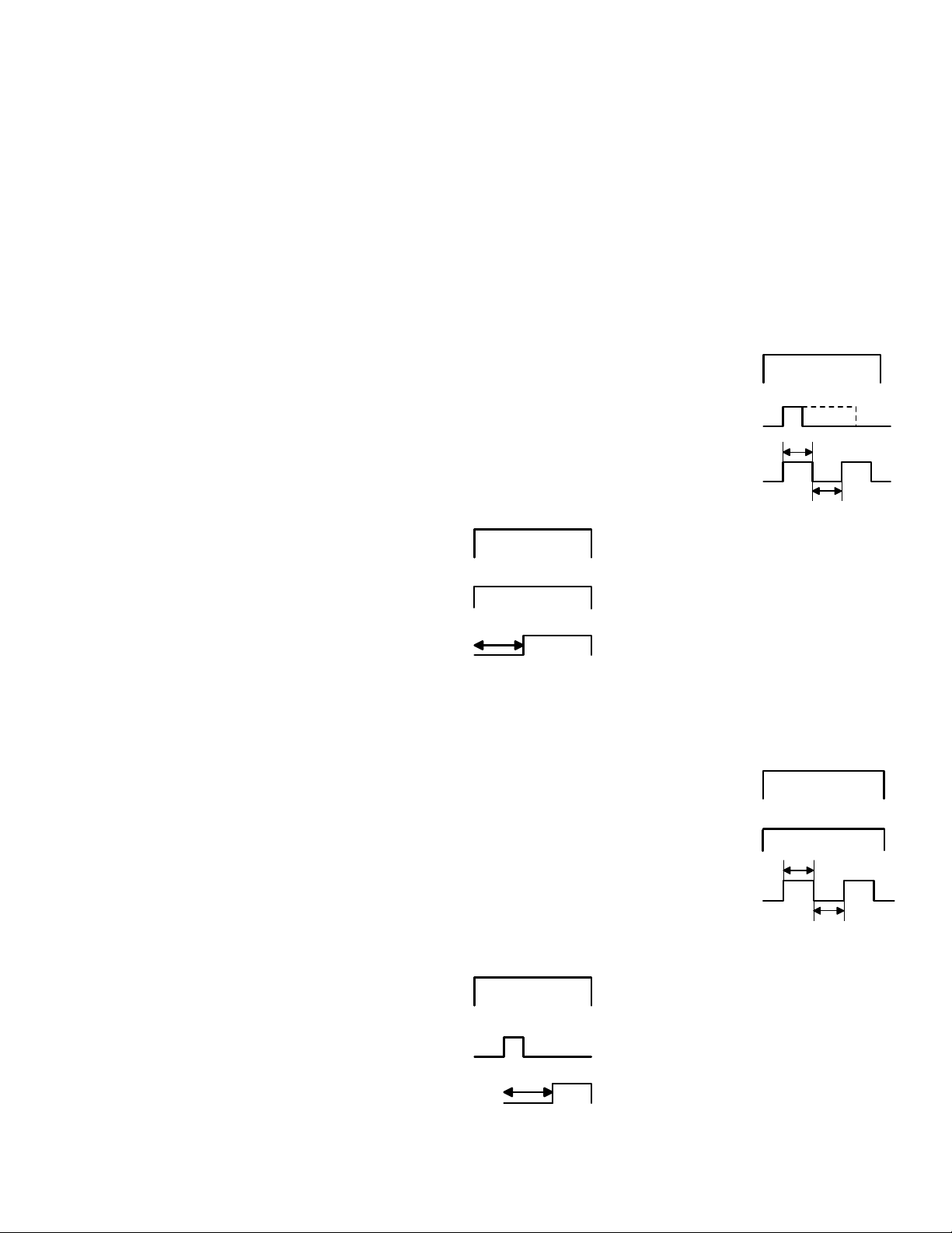
Mode A ON-delay
(Power-ON Start/Power OFF
Reset):
Connect start terminals (3
& 6). Upon application of power to
the timer, time delay period
begins. At the end of time delay
period, output contacts switches,
either connecting or disconnecting
load. Output remains switched
until power is removed or a reset
input is applied.
Power
2 - 10
Start 3 - 6
Output
9 - 11
ON
OFF
ON
OFF
ON
OFF
Timing
Figure 1
Mode A ON-delay
(Signal Start):
Power is applied
continuously. Time delay period
begins at the leading edge of start
input. Output contact switches
when the accumulated time equals
the set time. Subsequent start
signals during or after timing will
not be accepted. The output relay
will remain switched until a reset
input is applied or power is
interrupted.
Power
2 -10
Start 3 -6
Output
9 - 11
ON
OFF
ON
OFF
ON
OFF
Timing
Figure 2
Mode B Repeat Cycle - Signal
Start (50% fixed duty cycle):
Power is continuously applied.
The OFF/ON cycle is initiated at
the leading edge of the start input.
The output relay will be OFF for
the set time and ON for the set
time. The ON and OFF cycle will
continue to alternate until a reset
input is applied or power is
disconnected.
Power
2 -10
Start 3 - 6
Output
9 - 11
ON
OFF
ON
OFF
ON
OFF
On Time
Off Time
Figure 3
Mode B Repeat Cycle - Power
ON Start/Power-OFF Reset
(50% fixed duty cycle):
Connect
start terminals (3 & 6). Upon
application of power to the timer,
the OFF delay is initated for the
set time and then ON for the set
time. The ON and OFF cycle will
continue to alternate until a reset
input is applied or power is
disconnected.
Power
2 -10
Start 3 - 6
Output
9 - 11
ON
OFF
ON
OFF
ON
OFF
On Time
Off Time
Figure 4
Mode C
Signal Interval/OFF-delay:
Power is continously applied.
Time delay period begins on both
the leading and trailing edges of
the start input. Output contact
switches during time delay period,
either connecting or disconnecting
load. Once the timer has timed
out from the trailing edge, it resets
and is ready for subsequent start
inputs.
Refer to Figure 5.
Page 4

Product Operation and Setup Instructions 1A983
Operation (Continued)
Power
2 -10
Start 3 - 6
Reset 3 - 7
Output
9 - 11
Figure 5
Mode D
Signal OFF-delay ( l ):
Power is continuously applied.
The output relay switches at the
leading edge of the start input,
either connecting or disconnecting
load. Time delay period begins at
the trailing edge of the start input.
Output relay switches again when
accumalated time equals the set
time.
Power
2 -10
Start 3 - 6
Reset 3 - 7
Output
9 - 11
Figure 6
Mode E - Interval
Signal Start:
continously. Timing begins at the
leading edge of the start input.
The output relay is switched, either
connecting or disconnecting load,
only during timing. The timer is
reset when power is disconnected
or a reset input is applied.
Refer to Figure 7
ON
OFF
ON
OFF
ON
OFF
ON
t t tt
OFF
ON
OFF
ON
OFF
ON
OFF
t t
ON
OFF
Power is applied
Less than set time
Power
2 -10
Start 3 - 6
Output
9 - 11
Reset
3 - 7
Figure 7
ON
OFF
ON
OFF
ON
OFF
ON
OFF
Timing
Mode E - Interval
Power-ON Start/Power-OFF
reset:
Connect start terminals (3
& 6). Upon application of power to
the timer, timing starts. The output
relay is switched during timing,
either connecting or disconnecting
load. Output remains switched
until power is removed or a reset
input is applied.
tt
Power
2 -10
Start 3 - 6
Output
9 - 11
ON
OFF
ON
OFF
ON
OFF
Timing
Timing
Figure 8
Mode F Cycle One-shot
Power-On Short/Power-OFF
Reset:
Connect start terminals (3
& 6). Upon application of power to
the timer, timing starts. The output
relay is OFF for the set time and
then ON for the set time for one
cycle only. The timer is reset
when power is removed or a reset
input is applied.
Power
2 -10
t
Start 3 - 6
Output
9 - 11
ON
OFF
ON
OFF
ON
OFF
Off for set
time
On for set
time
Figure 9
Mode F Cycle One-shot
Signal Start:
Power is
continously applied. The OFF/ON
cycle is initated at the leading
Timing
edge of the start input. The
output relay will be OFF for the set
time and then ON for the set time
for one cycle only. The timer is
reset when power is removed or a
reset input is applied.
Refer to
Figure 10.
Page 5

Product Operation and Setup Instructions 1A983
Operation (Continued)
Power
2 -10
Start 3 - 6
Output
9 - 11
Figure 10
Mode G
Signal ON-delay/OFF-delay:
Power is continuously applied.
Timing begins on both the leading
and trailing edges of the start
input. The output relay switches
when the accumulated time from
the leading edge equals the set
time, either connecting or
disconnecting load. It also
switches for the set amount of time
from the trailing edge of the start
input.
ON
OFF
ON
OFF
ON
OFF
Off for set
time
On for set
time
Mode H
Signal OFF-delay:
Power is continuously applied.
Timing begins at the trailing edge
of the start input. The output relay
is switched only during timing.
Power 2 -10
Start 3 - 6
Output 9 - 11
ON
OFF
ON
OFF
ON
Timing
OFF
Figure 12
Timing
Power 2 10
Start 3 - 6
Output 9 11
Reset 3 - 7
Figure 11
ON
OFF
ON
OFF
ON
OFF
ON
OFF
Timing
Timing Timing Timing
Page 6

Product Operation and Setup Instructions 1A983
Application
ON-DELAY Power-ON Start/
Power-OFF Reset
Refer to Figures A, B, and C
1. Power is applied to pins 2 and
10.
2. Jumper start input, pins 3 and 6
together.
3. Jumper one side of power
(either pin 2 or 10) to COM of
output relay (pin 11).
4. Load is activated through pin 9
(normally open contact) and the
other side of power not
connected to COM (pin 11).
5. Time period begins upon
application of power, once the
time delay period ends,
output relay energizes and
contacts transfer, activating
load.
6. Reset timer by applying a switch
closure to reset input (pins 3
and 7) or by removing power
from pins 2 or 10.
ON-DELAY Signal Start
Refer to Figures A, B, and C
1. Power is applied to pins 2 and
10.
2. Jumper one side of power
(either pin 2 or 10) to COM of
output relay (pin 11).
3. Load is activated through pin 9
(normally open contact) and the
other side of power not
connected to COM (pin 11).
4. Once start input is closed (pins
3 and 6), output relay energizes
and contacts transfer, activating
load.
5. Reset timer by applying a switch
closure to reset input (pins 3
and 7) or by removing power
from pins 2 or 10.
REPEAT CYCLE - Signal Start
Refer to Figures A, B, and C
1. Power is applied to pins 2 and
10.
2. Jumper one side of power
(either pin 2 or 10) to COM of
output relay (pin 11).
3. Load is activated through pin 9
(normally open contact) and the
other side of power not
connected to COM (pin 11).
4. Once start input is closed (pins
3 and 6), output relay begins
cycling, thus activating and
deactivating the load.
5. Reset timer by applying a switch
closure to reset input (pins 3
and 7) or by removing power
from pins 2 or 10.
REPEAT CYCLE - Power ON
Start/Power-OFF Reset
Refer to Figures A, B, and C
1. Power is applied to pins 2 and
10.
2. Jumper start input, pins 3 and 6
together.
3. Jumper one side of power
(either pin 2 or 10) to COM of
output relay (pin 11).
4. Load is activated through pin 9
(normally open contact) and the
other side of power not
connected to COM (pin 11).
5. Upon application of power,
output relay begins cycling, thus
activating and deactivating the
load.
6. Reset timer by applying a switch
closure to reset input (pins 3
and 7) or by removing power
from pins 2 or 10.
SIGNAL INTERVAL/OFF-DELAY
Refer to Figures A, B, and C
1. Power is applied to pins 2 and
10.
2. Jumper start input, pins 3 and 6
together.
3. Jumper one side of power
(either pin 2 or 10) to COM of
output relay (pin 11).
4. Load is activated through pin 9
(normally open contact) and the
other side of power not
connected to COM (pin 11).
5. Time period begin each time
start input is closed and
opened. Load is activated only
during time period.
6. Reset is established once timer
has timed out after start input
was opened or power is
removed from pins 2 or 10.
SIGNAL OFF-DELAY ( l )
Refer to Figures A, B, and C
1. Power is applied to pins 2 and
10.
2. Jumper start input, pins 3 and 6
together.
3. Jumper one side of power
(either pin 2 or 10) to COM of
output relay (pin 11).
4. Load is activated through pin 9
(normally open contact) and the
other side of power not
connected to COM (pin 11).
5. Once start input is closed, load
is activated and stays activate
as long as start input is closed
or time period expires.
6. Reset timer by applying a switch
closure to reset input (pins 3
and 7) or by removing power
from pins 2 or 10.
INTERVAL Signal Start
Refer to Figures A, B, and C
1. Power is applied to pins 2 and
10.
2. Jumper start input, pins 3 and 6
together.
3. Jumper one side of power
(either pin 2 or 10) to COM of
output relay (pin 11).
4. Load is activated through pin 9
(normally open contact) and the
other side of power not
connected to COM (pin 11).
5. Once start input is closed (pins
3 and 6), output relay activates
load during time period and
deactivates load once time
period ends.
6. Reset timer by applying a switch
closure to reset input (pins 3
and 7) or by removing power
from pins 2 or 10.
Page 7

Product Operation and Setup Instructions 1A983
Application (Continued)
INTERVAL Power-ON Start/
Power-OFF reset
Refer to Figures A, B, and C
1. Power is applied to pins 2 and
10.
2. Jumper start input, pins 3 and 6
together.
3. Jumper one side of power
(either pin 2 or 10) to COM of
output relay (pin 11).
4. Load is activated through pin 9
(normally open contact) and the
other side of power not
connected to COM (pin 11).
5. Time period begins upon
application of power, the
time period begins, output relay
energizes and contacts transfer,
activating load. The load is
activate only during timing
period
6. Reset timer by applying a switch
closure to reset input (pins 3
and 7) or by removing power
from pins 2 or 10.
CYCLE One-Shot
Power-ON Short/Power-OFF
Reset
Refer to Figures A, B, and C
1. Power is applied to pins 2 and
10.
2. Jumper start input, pins 3 and 6
together.
3. Jumper one side of power
(either pin 2 or 10) to COM of
output relay (pin 11).
3. Load is activated through pin 9
(normally open contact) and the
other side of power not
connected to COM (pin 11).
4. Once start input is closed (pins
3 and 6), output relay energizes
and contacts transfer, activating
load.
5. Time period begins upon
application of power, output
relay cycles OFF for the set
time and then ON for only one
cycle.
6. Reset timer by applying a switch
closure to reset input (pins 3
and 7) or by removing power
from pins 2 or 10.
CYCLE One-Shot
Signal Start
Refer to Figures A, B, and C
1. Power is applied to pins 2 and
10.
2. Jumper one side of power
(either pin 2 or 10) to COM of
output relay (pin 11).
3. Load is activated through pin 9
(normally open contact) and the
other side of power not
connected to COM (pin 11).
4. Once start input is closed,
output relay cycles OFF for the
set time and then ON for only
one cycle.
5. Reset timer by applying a switch
closure to reset input (pins 3
and 7) or by removing power
from pins 2 or 10.
SIGNAL ON-DELAY/OFF-DELAY
Refer to Figures A, B, and C
1. Power is applied to pins 2 and
10.
2. Jumper one side of power
(either pin 2 or 10) to COM of
output relay (pin 11).
4. Load is activated through pin 9
(normally open contact) and the
other side of power not
connected to COM (pin 11).
5. Time period begin each time
start input is closed and
opened. Load is activated when
the accumulated time from the
last start input closure equals
the set time. The load is also
activate for the set time period
immediately after the start input
is opened.
6. Reset timer by applying a switch
closure to reset input (pins 3
and 7) or by removing power
from pins 2 or 10.
SIGNAL OFF-DELAY ( ll )
Refer to Figures A, B, and C
1. Power is applied to pins 2 and
10.
2. Jumper one side of power
(either pin 2 or 10) to COM of
output relay (pin 11).
3. Load is activated through pin 9
(normally open contact) and the
other side of power not
connected to COM (pin 11).
4. Load is activated for the
duration of the set time period
only after the start input has
been closed then opened.
5. Reset timer by applying a switch
closure to reset input (pins 3
and 7) or by removing power
from pins 2 or 10.
Page 8

Product Operation and Setup Instructions
1A983
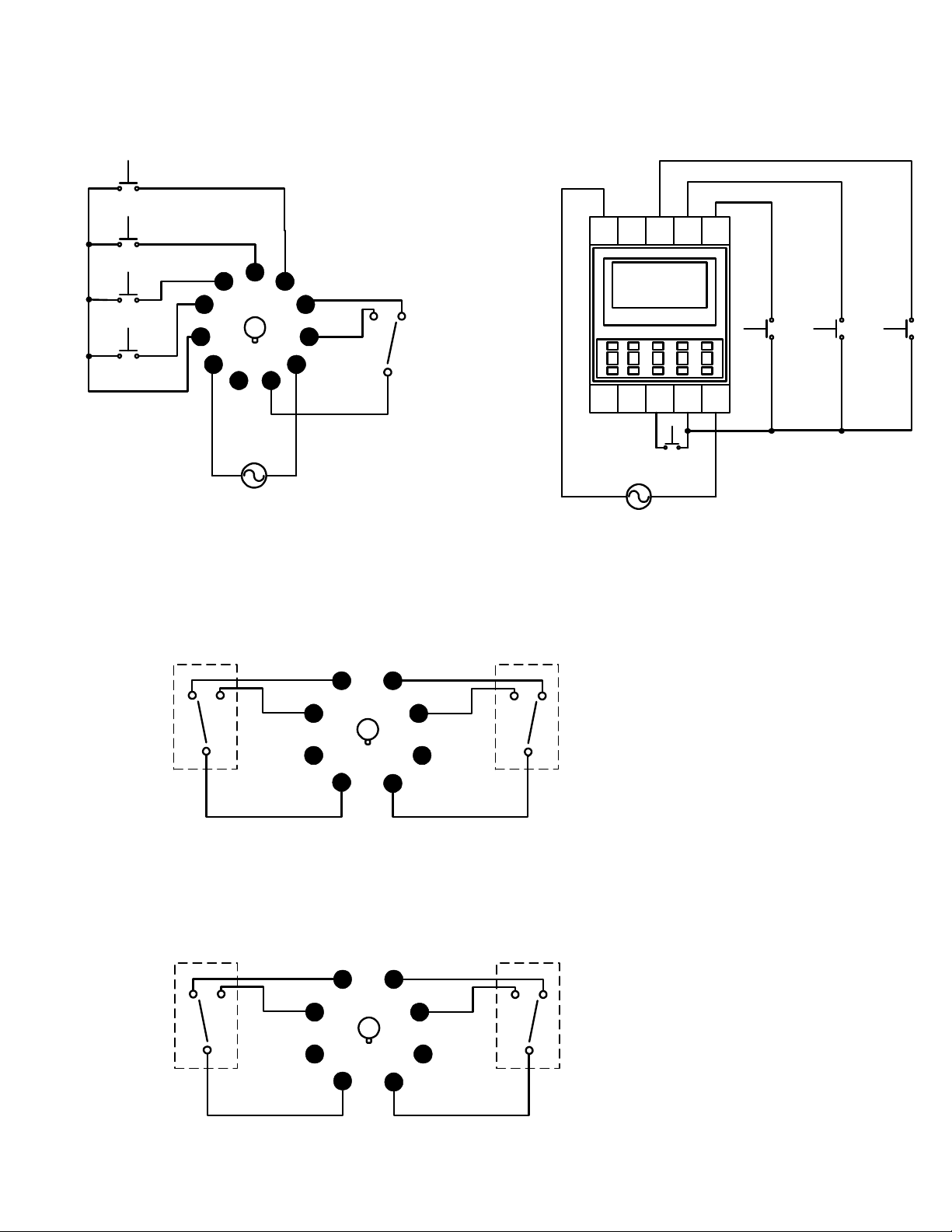
Wiring Diagrams
Reset
Start
6
5
H3CA-A
4
CO
M
3
Jumper
wire
2
Supply Voltage
Figure A Figure B
7
8
9
10
1
11
L L
Figures A, B, and C illustrate
how to wire the load to utilize
the very same supply
voltage going to the timer.
Jumper
wire
A
15D1C1B
1
H3CA-FA
1618E
Supply voltage
can be either a
AC or DC
source
1
Reset Start
A
X
1
2
L1
Reset
L2
Start
4
5
H3CA-8
3
2
1
Jumper
wires
Supply Voltage
Figure C Figure D
6
7
8
Figure D illustrates how to
wire the load to utilize a
separate power source then
the one used by the timer.
CO
M
5
H3CA-A
4
3
2
Supply Voltage
6
7
8
9
10
1
11
L
DC
Page 9

PRODUCT WARRANTY
NOTE: Specifications to change without notice.
Omron certifies all of its products either meet or exceed stipulated specifications.
Omron is not liable for stenographic and/or clerical errors.
Omron's obligation under this warranty is limited solely to repair or replacement at
Omron's discretion. Omron will not be liable for any design furnished by Buyer and
incorporated into equipment.
This warranty is voided if the product is altered in any way or suffers consequential
damage due to negligence or misuse.
Omron is not to suffer risk due to suitability or unsuitability or the results of the use of its
products used in combination with any electrical or electronic components, circuits,
systems assemblies, or any other materials or substances or environments.
The foregoing warning is the only warranty which Omron Electronics, Inc. provides with
respect to the products listed herein. No other warranties, expressed, implied, or
statutory shall apply, whether as to merchantability, fitness for a particular purpose,
description, or otherwise.
This warranty is extended to three years for temperature and process controllers.
Limitation of Liability: Notwithstanding any other statement herein, Omron
Electronics, Inc., its contractors and suppliers, shall not be liable for any special,
indirect, incidental, or consequential damages.
The remedies of the purchaser set forth herein are exclusive where so stated and the
total cumulative liability of Omron Electronics, Inc., its contractors and suppliers, with
respect to this contract or anything done in connection therewith, shall not exceed
replacement price reimbursement as to the product on which such liability is based.
 Loading...