

Page 1
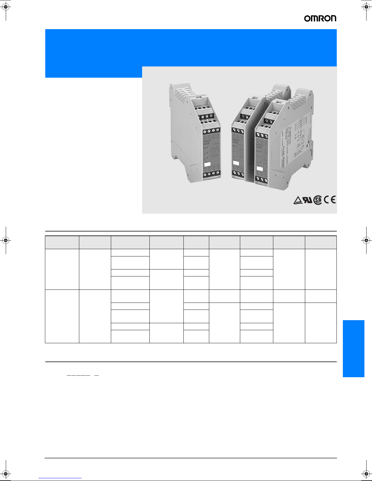
Safety Relay Unit
G9SB
Ultra Slim Safety
Relay Unit
• Models of width 17.5 mm available with
2 or 3 safety contacts. Models of width
22.5 mm with 3 safety contacts and
auxiliary contact are also available.
• Conforms to EN standards.
(TÜV approval)
• DIN track mounting possible.
• Slim size controller dedicated for safey
sensors F3SN, F3SH, F3S-B, F3STGR, F3SL, F3S-J
Ordering Information
Main contacts
DPST-NO
2 safety
contacts
3PST-NO
3 safety
contacts
Auxiliary
contact
None
SPST-NC
Number of input
channels
2 channels
1 channel or
2 channels
2 channels
1 channel or
2 channels
None
(direct breaking)
2 channels Inverse
1 channel or
2 channels
2 channels
1 channel or
2 channels
Model Number Legend
G9SB-##### #
1 2 3 4 5 6
1. Function
None: Emergency stop
2. Contact Configuration (Safety Output)
2: DPST-NO
3: 3PST-NO
3. Contact Configuration (OFF-delay Output)
0: None
4. Contact Configuration (Auxiliary Output)
0: None
1: SPST-NC
Reset mode Input type
Inverse
Auto-reset
Manual-reset
Auto-reset
Manual-reset
+ common G9SB-200-B
Inverse G9SB-2002-C
+ common G9SB-200-D
--- 24 VDC G9SB-3010 3 17.5 mm
+ common G9SB-301-B
Inverse G9SB-3012-C
+ common G9SB-301-D
Rated
voltage
24 VAC/VDC
24 VAC/VDC
5. Input Configuration
None: 1-channel or 2-channel input possible
0: None (direct breaking)
2: 2-channel input
6. Miscellaneous
A: Auto-reset, inverse input
B: Auto-reset, + common input
C: Manual-reset, inverse input
D: Manual-reset, + common input
Model
G9SB-2002-A
4 17.5 mm
G9SB-3012-A
4 22.5 mm
Category
(EN954-1)
Size
G9SB
G-123G9SB
Page 2

Specifications
Ratings
Power Input
Item G9SB-200#-# G9SB-3010 G9SB-301#-#
Power supply voltage
Operating voltage range 85% to 110% of rated power supply voltage
Power consumption 1.4 VA/1.4 W max. 1.7 W max. 1.7 VA/1.7 W max.
Inputs
Item G9SB-200#-# G9SB-3010 G9SB-301#-#
Input current 25 mA max. 60 mA max. (See note.) 30 mA max.
Note: Indicates the current between terminals A1 and A2.
Contacts
Item
Rated load 250 VAC, 5 A
Rated carry current 5 A
Characteristics
Contact resistance (See note 1.) 100 mΩ
Operating time (See note 2.) 30 ms max.
Response time (See notes 2 and 3.) 10 ms max.
Insulation resistance (See note 4.) 100 MΩ min. (at 500 VDC)
Dielectric strength
Vibration resistance 10 to 55 to 10 Hz, 0.375-mm single amplitude (0.75-mm double amplitude)
Shock resistance
Durability
Minimum permissable load
(reference value)
Ambient operating temperature -25 to 55°C (with no icing or condensation)
Ambient operating humidity 35% to 85%
Terminal tightening torque 0.5 N·m
Weight Approx. 115 g Approx. 135 g Approx. 120 g
Approved standards EN954-1, EN60204-1, UL508, CSA C22.2 No. 14
EMC
24 VAC/VDC: 24 VAC, 50/60 Hz, or 24VDC
24 VDC: 24 VDC
G9SB-200#-# G9SB-3010 G9SB-301#-#
Resistive load (cos =1)
Item G9SB-200#-# G9SB-3010 G9SB-301#-#
Between different
outputs
Between inputs
and outputs
Between power inputs and outputs
Destruction 300 m/s
Malfunction 100 m/s
Mechanical 5,000,000 operations min. (at approx. 7,200 operations/hr)
Electrical 100,000 operations min. (at approx. 1,800 operations/hr)
2,500 VAC, 50/60 Hz for 1 min
2
2
5 VDC, 1 mA
EMI: EN55011 group 1 class A
EMS: EN50082-2
Note: 1. The contact resistance was measured with 1 A at 5 VDC using the voltage-drop method.
2. The bounce time is not included in the figure for operating time.
3. The response time is the time it takes for the main contact to open after the input is turned OFF.
4. The insulation resistance was measured with 500 VDC at the same places that the dielectric strength was checked.
G-124 Safety Sensors / Components
Page 3
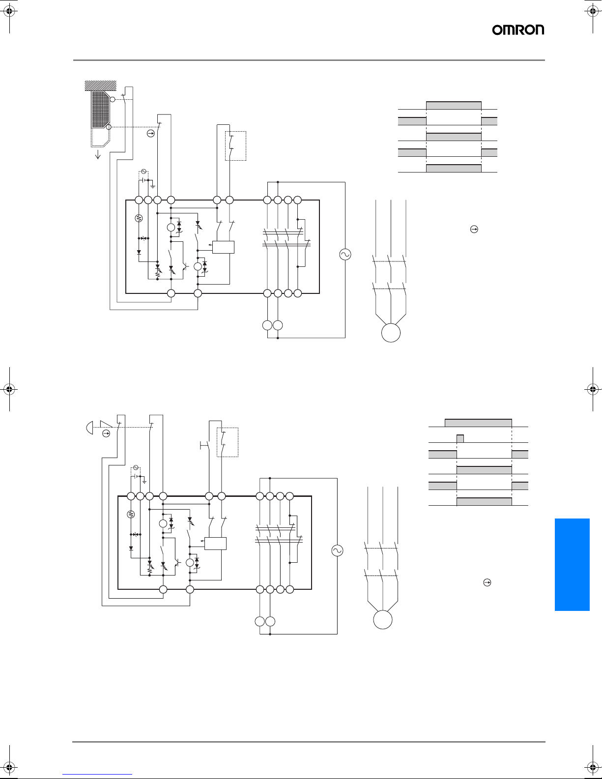
Application Examples
G9SB-2002-A (24 VAC/VDC) or G9SB-3012-A (24 VAC/VDC) with 2-channel Limit Switch Input/Auto-reset
Timing Chart
Limit switches S1 and S2
K1 and K2 (NC)
K1 and K2 (NO)
KM1 and KM2 (NC)
KM1 and KM2 (NO)
Open
23
S2
24
11
S1
12
KM1
KM2
Feedback loop
A1 A2
T11 T12 T31 T32
+
-
K1
TH
SA
T21
K1
a
K2
K2
T22
K2 K1
Control
a
circuit
K1
K2
13 23
14 24
KM1
KM2
**
33 41
34 42
**
See note.
KM1
KM2
S1: Safety limit switch with direct
S2: Limit switch
KM1 and KM2: Magnetic Contactor
M: 3-phase motor
Note: Only the G9SB-3012-A
opening mechanism (D4N or
D4B)
model has terminals 33-34
and 41-42.
M
Note: 1. External connections and timing charts for G9SB-200-B/301-B models are the same as those for G9SB-2002-A/3012-A models.
2. This circuit conforms to EN954-1 Safety Category 4.
G9SB-2002-C (24 VAC/VDC) or G9SB-3012-C (24 VAC/VDC)
with 2-channel Emergency Stop Switch Input/Manual-reset
S1
21
22
A1 A2
+
TH
SA
11
12
T11
T12 T31 T32
-
K1
K1
T21
a
K2
K2
T22
S2
K2 K1
Control
a
circuit
KM1
KM2
Feedback loop
K1
K2
13 23
14 24
KM1
KM2
*
*
33 41
34 42
**
See note.
Note: 1. External connections and timing charts for G9SB-200-D/301-D models are the same as those for G9SB-2002-C/3012-D models.
2. This circuit conforms to EN954-1 Safety Category 4.
Timing Chart
Emergency stop switch S1
Reset switch S2
K1 and K2 (NC)
K1 and K2 (NO)
KM1
KM2
M
KM1 and
KM2 (NC)
KM1 and
KM2 (NO)
Note: Output turns ON with the ri-
sing edge of reset switch S2,
but will not operate if there is
a short breakdown in S2.
S1: Emergency stop switch with
S2: Reset switch
KM1 and KM2: Magnetic Contactor
M: 3-phase motor
direct opening mechanism
(A165E, A22E)
Note: Only the G9SB-3012-C model
has terminals 33-34 and 41-
42.
G9SB
G-125G9SB
Page 4
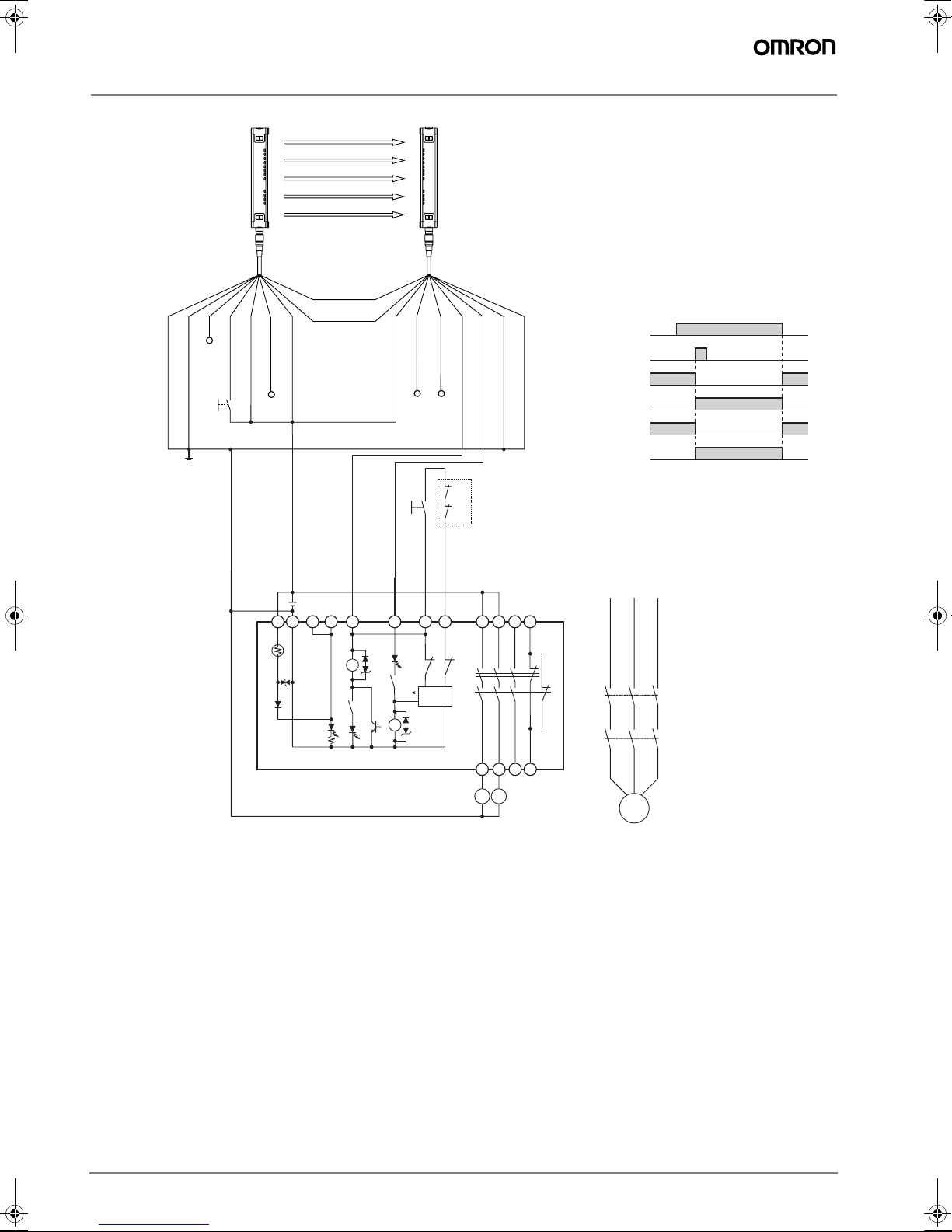
G9SB-200-D (24 VAC/VDC) or G9SB-301-D (24 VAC/VDC) with 2-channel Safety Area Sensor/Manual-reset
Emitter Receiver
F3SN-A
F3SH-A
RS-485(A) (Gray)
Timing Chart
F3SN-A: Incident
Interrupted
Reset switch S1
K1 and K2 (NC)
K1 and K2 (NO)
KM1 and KM2 (NC)
KM1 and KM2 (NO)
Note: Output turns ON with the rising edge of re-
set switch S1, but will not operate if there is
a short breakdown in S1.
F3SN-A: Safety Area Sensor
S1: Reset switch
KM1 and KM2: Magnetic Contactor
M: 3-phase motor
E1: 24-VDC power supply
Shield
(Red)
0V (Blue)
Open
Reset input (Yellow)
Test input (Green)
RS-485(B) (Pink)
+24 V (Brown)
Interlock selection
input (White)
Open
Auxiliary (Yellow)
EDM input (Red)
+24 V (Brown)
Open
S1
OSSD2 (White)
OSSD1 (Green)
Open
Feedback loop
KM1
KM2
Shield
0V (Blue)
E1
A1 A2
T11 T12 T31 T32
T21
+
-
TH
SA
K1
K1
a
Note: This circuit conforms to EN954-1 Safety Category 4.
T22
K2
K2
a
K2 K1
Control
circuit
K1
K2
KM1
134133
23
14 24
KM2
**
34 42
**
See note.
KM1
KM2
Note: Only the G9SB-301-D
model has terminals
33-34 and 41-42.
M
G-126 Safety Sensors / Components
Page 5
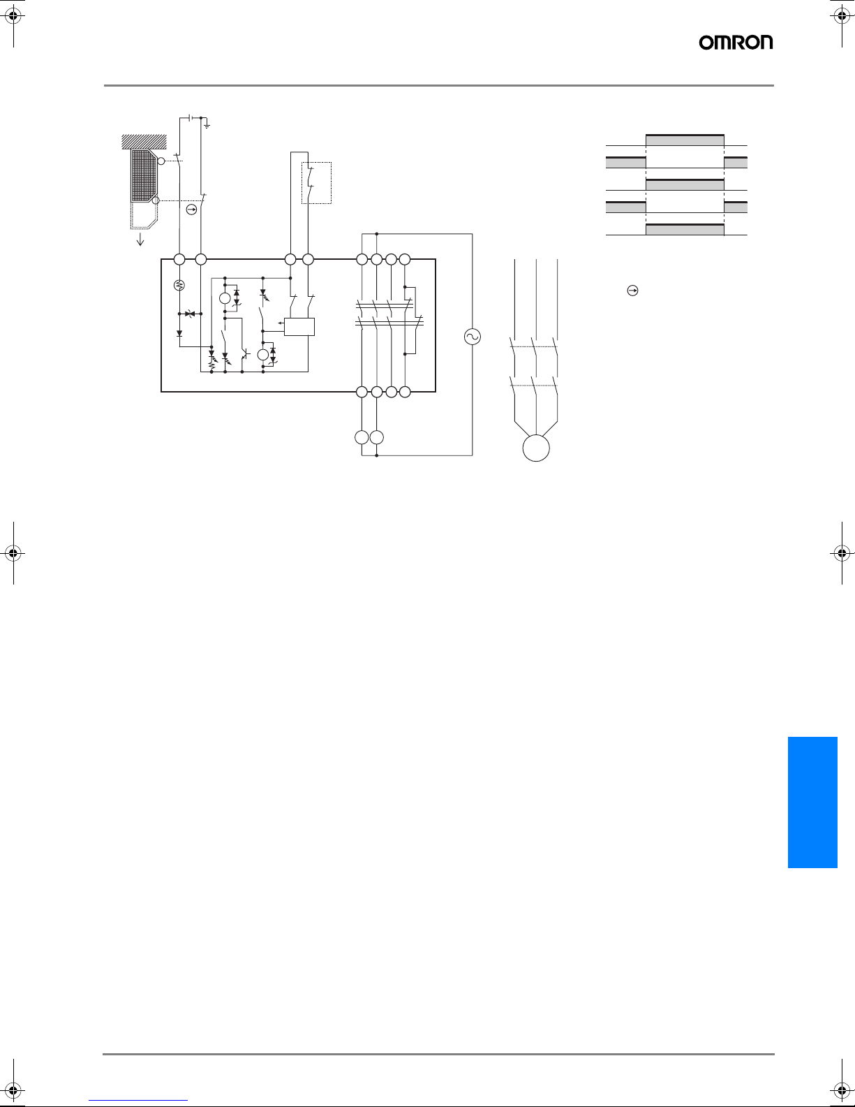
G9SB-3010 (24 VDC) with 2-channel Limit Switch Input/Auto-reset
23
S2
Open
24
S1
A1 A2
+
TH
SA
11
12
-
K1
K2
K1
a
a
K2
Feedback loop
T31 T32
K2 K1
Control
circuit
KM1
KM2
13
23 33
41
K1
K2
KM1
Timing Chart
Limit switches S1 and S2
K1 and K2 (NC)
K1 and K2 (NO)
KM1 and KM2 (NC)
KM1 and KM2 (NO)
S1: Safety limit switch with direct
S2: Limit switch
KM1 and KM2: Magnetic Contactor
M: 3-phase motor
opening mechanism (D4D or D4B)
14 24 34 42
KM1
Note: This circuit conforms to EN954-1 Safety Category 3.
KM2
KM2
M
G9SB
G-127G9SB
Page 6
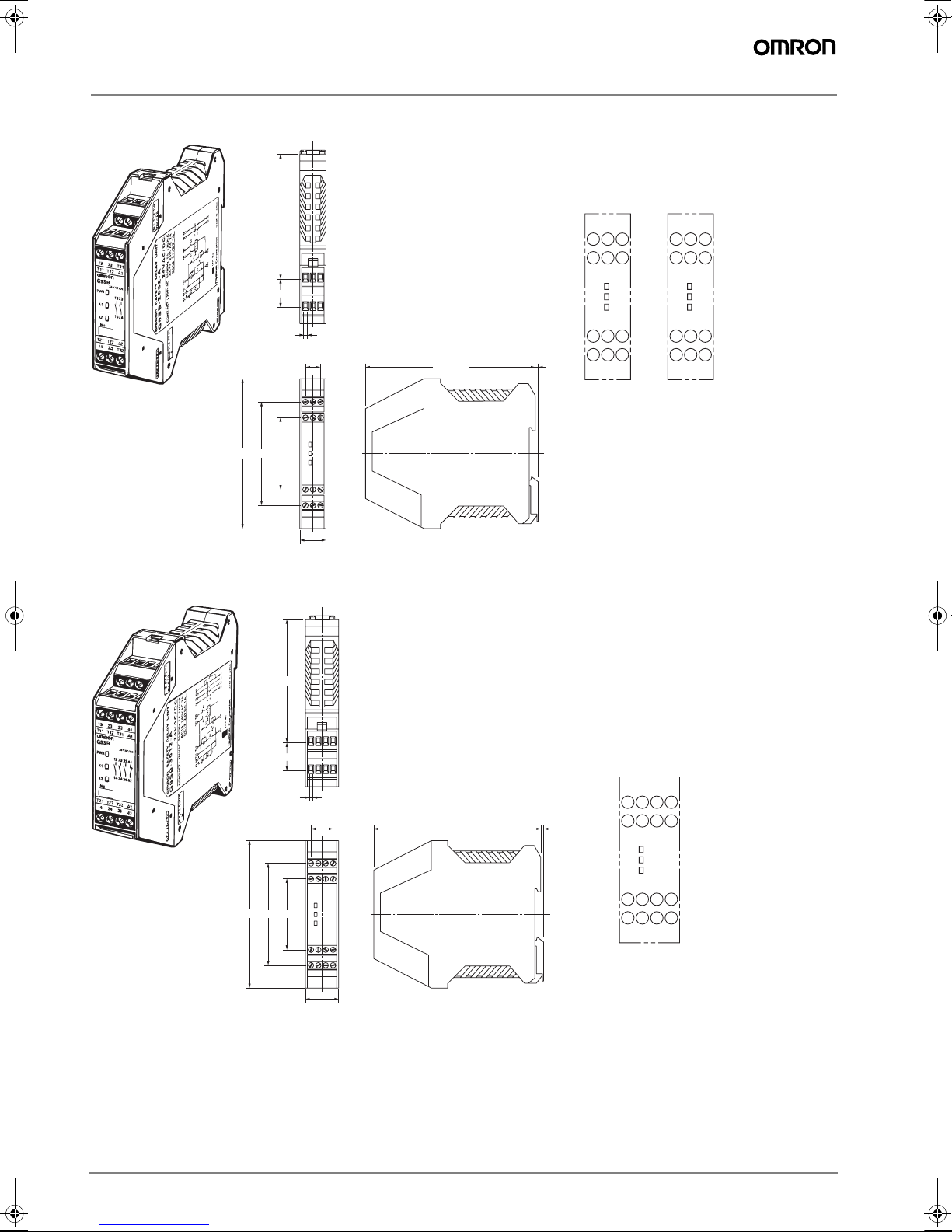
Dimensions
G9SB-200#-#
G9SB-3010
Terminal Arrangement
A1
G9SB-3010
13 23 33
41
T31
A1
83
G9SB-200#-#
13 23
T31
T11
T12
G9SB-301-#
100 max.
68 48
18
2.5
2 ¥ 5 = 10
18 max.
(Average: 17.5)
83
112 max.
(green)
PWR
(orange)
K1
(orange)
K2
T21 T22
A2
24
T32
14
2.6
PWR
K1
K2
T32
42
14 24 34
(green)
(orange)
(orange)
A2
100 max.
68 48
18
2.5
3 ¥ 5 = 15
23 max.
(Average: 22.5)
112 max.
Terminal Arrangement
G9SB-200#-#
13 23 33
2.6
T11 T12 T31
PWR
K1
K2
T21 T22 T32
14 24 34
(green)
(orange)
(orange)
41
A1
A2
42
G-128 Safety Sensors / Components
Page 7
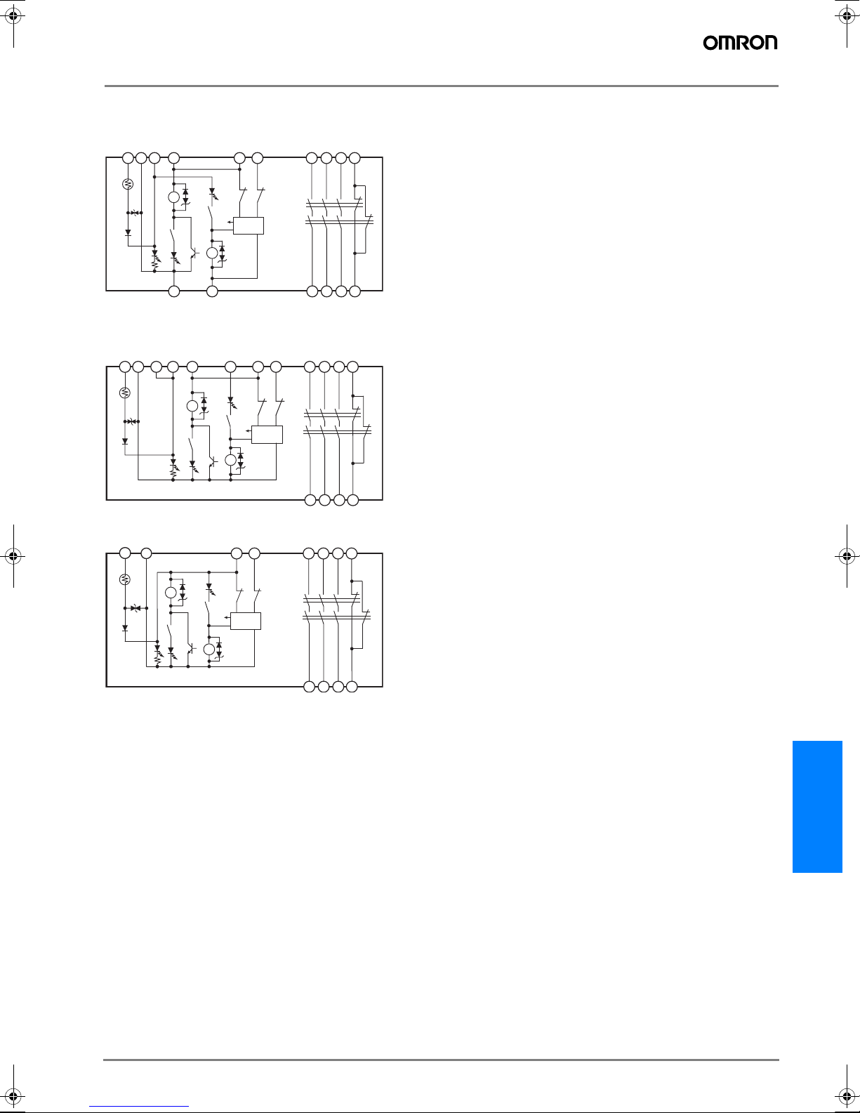
Installation
Internal connections
G9SB-2002-A/C (24 VAC/VDC)
G9SB-3012-A/C (24 VAC/VDC)
T11
A1 A2
T12 T31 T32
+
-
13 23
**
33 41
a
K2
K2
T22
K2 K1
Control
a
circuit
TH
K1
SA
K1
T21
G9SB-200-B/D (24 VAC/VDC)
G9SB-301-B/D (24 VAC/VDC)
A1 A2
+
TH
SA
T11 T12 T31 T32
T21
-
T22
K1
K1
a
K2
a
K2
K2 K1
G9SB-3010 (24 VDC)
A1 A2
+
TH
SA
-
K1
K1
T31 T32
K2 K1
K2
Control
a
circuit
a
K2
Control
circuit
K2
K1
K2
K1
K2
K1
14 24
13
14
13
34 42
**
See note 2.
**
23
33
24
34 42
**
See note 2.
23 33
41
41
Note: 1. For 1-channel input with G9SB-###-B/D models, short terminals T12 and T22.
It is not possible to wire G9SB-###2-A/C models for 1-channel input.
2. Only G9SB-301#-# models have terminals 33-34 and 41-42.
14 24 34 42
G9SB
G-129G9SB
Page 8
Precautions
Wiring
Turn OFF the G9SB before wiring. Do not touch the terminals
of the G9SB while the power is turned ON, because the terminals are charged and may cause an electric shock.
Use the following to wire the G9SB.
Stranded wire:0.2 to 2.5 mm
Solid wire:0.2 to 2.5 mm
Tighten each screw to a torque of 0.5 to 0.6 N·m, or the G9SB
may malfunction or generate heat.
External inputs connected to T11 and T12 or T21 and T22 of
the G9SB must be no-voltage contact inputs.
plicable Safety Category
Ap
G9SB-200#-#/301#-# meet the requirements of Safety Category 4 of the EN954-1 standards when they are used as
shown in the examples provided by OMRON. Relays may not
meet the standards in some operating conditions. The G9SB3010 can be applied to Safety Category 3 of the EN954-1 using double breaking. The applicable safety category is determined from the whole safety control system. Make sure that
the whole safety control system meets EN954-1 requirements.
2
2
Mounting Multiple Units
When mounting multiple Units close to each other, the rated
current will be 3 A. Do not apply a current higher than 3 A.
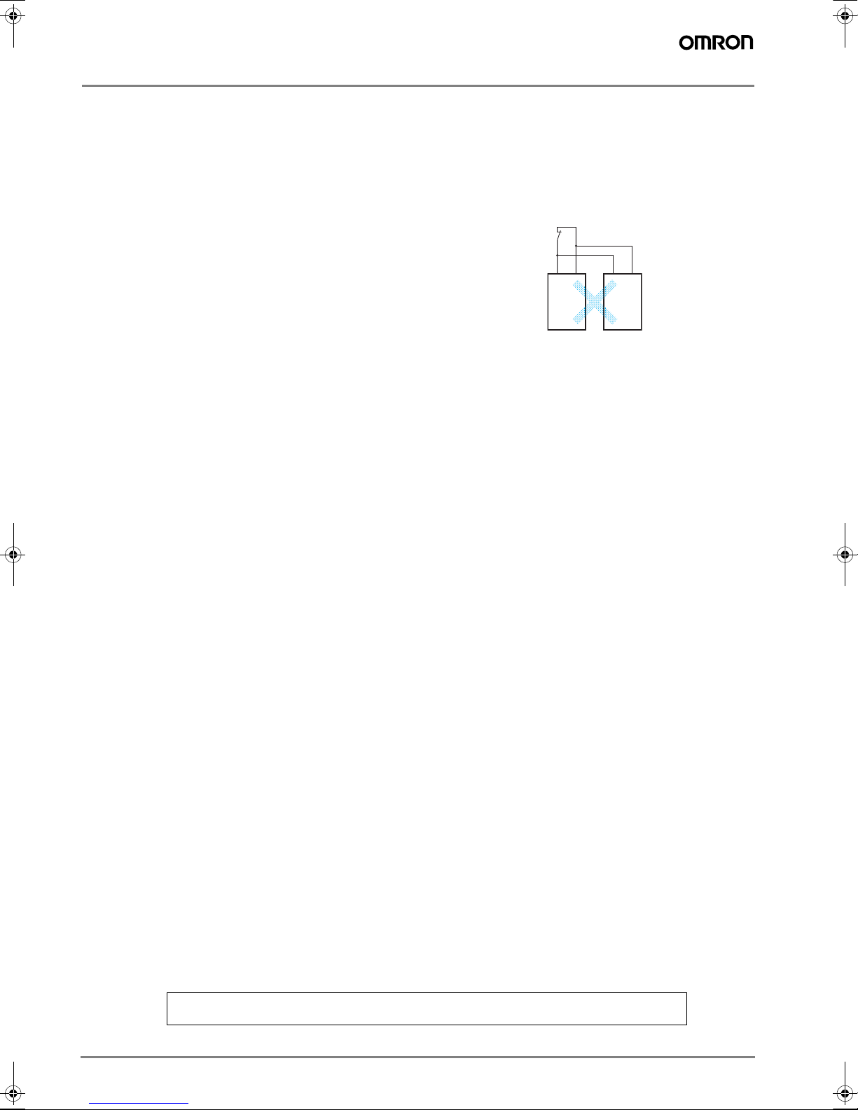
Connecting Inputs
If using multiple G9SB models, inputs cannot be made using
the same switch. This is also true for other input terminals.
T11 T12 T11 T12
G9SB G9SB
Earth Short
A positive thermistor is built into the G9SB circuits, so you can
detect earth short breakdowns and breakdown shorts between channel 1 and channel 2. (Detection of breakdown
shorts between channel 1 and channel 2 is supported for
G9SB-2002-#/3012-# models only.)
Note: In order to detect earth short breakdowns, connect the minus side of the
power supply to ground.
ALL DIMENSIONS SHOWN ARE IN MILLIMETERS.
To convert millimeters into inches, multiply by 0.03937. To convert grams into ounces, multiply by 0.03527.
Cat. No. J130-E2-01-X
In the interest of product improvement, specifications are subject to change without notice.
G-130 Safety Sensors / Components
 Loading...