

Page 1
New Product News
Power Relays
G7Z
High-capacity Power Relays Capable
of Carrying and Switching 40 A at 440 VAC
Compact
40%
smaller than
contactors (IEC-
AC1, 50-A
High
specifications)
High
Capacity
IEC-AC1 40-A rating
4-pole power fully applied:
160 A
Mirror Contacts
for
Safety Function
Insulation
Load switching for
400-VAC systems
Low
Noise
Approx. 70 dB
Low Power
Consumption
Less than 4 W DC
RoHS
Compliant
Simple
Mounting
Page 2
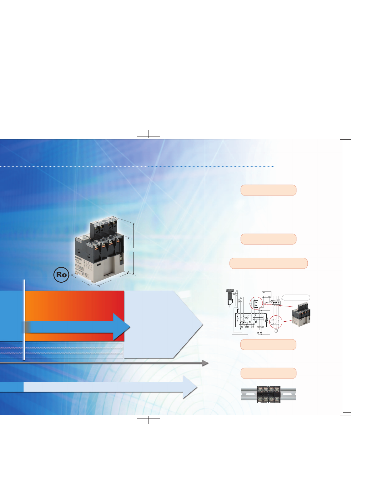
Current capacity
Conventional usage division
Contactor
current
range
G7Z
Expansion of relay range
G7Z
TH
SA
Downsizing of approximately 40% volume compared with contactors.*
Contributes to space savings in control panels.
* IEC-AC1 50-A specifications
The Relay can be easily mounted right on a DIN Track.
Application Example: General Safety Circuit
G9SA-301 (24-V AC/DC) (two limit switchinput channels with manual reset)
Compact Size
Safety Function with Mirror Contacts
Low Noise and
Low Power Consumption
DIN Track Mountable
Feedback circuit
Continuously apply 40 A at 440 VAC,
or apply up to a maximum of 160 A
by using 4-pole parallel connections
for full power application.*
The Relays are highly insulated to
support load switching
of 40 A at 440 VAC
EN 60947-4-1 certification for mirror contact mechanisms has been obtained by
using a combination of a relay and auxiliary contact blocks (5 VDC, 1 mA),
enabling application in feedback circuits of safety circuits.
* IEC-AC1 50-A specifications
Low noise of approx. 70 dB compared with the approx.
100 dB for contactors.* Low power consumption of less
than 4 W DC. Environmentally friendly specifications.
* Always consult with your OMRON representative
before using the maximum current of 160 A.
High Capacity and
High Insulation
84 mm
60 mm
62 mm
45 mm
Feedbackloop
Control
circuit
Open
Page 3

4 Power Relays G7Z
Power Relays
G7Z
Multi-pole Power Relay fo r Contactor Current
Range Capable of Carrying and Switching
40 A at 440 VAC
• One pole, 40 A can be carried and switched.
• The maximum loa d capacity of 160 A when using 4-pole par allel
connections.
• All materials used are compliant with the RoHS Directive
• EN 60947-4-1 certification for mirror contact mechanisms has
been obtained b y us ing a co mbin ation of t he rela y and auxi liary
contact blocks.
Note: Re fer to th e Pr ecaut ions for Correct Use on page 9.
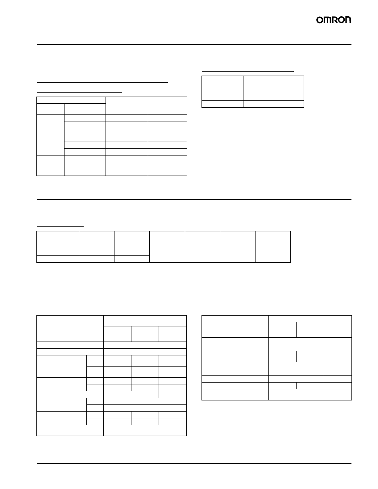
Model Number Structure
■Model Numbe r Legend
Relay with Auxiliary Contact Block
1. Relay Contact Configuration
4A: 4PST-NO
3A1B: 3PST-NO/SPS T-NC
2A2B: DPST-NO/DPST-NC
2. Contact Configuration of Auxiliary Contacts
20: DPST-NO
11: SPST-NO/SPST-NC
02: DPST-NC
3. Contact Mechanism of Auxiliary Contacts
Z: Bifurcated crossbar contact
Auxiliary Contact Block
1. Contact Configuration of Auxiliary Contacts
20: DPST-NO
11: SPST-NO/SPST-NC
02: DPST-NC
2. Contact Mechanism of Auxiliary Contacts
Z: Bifurcated crossbar contact
■Configuration
Note: 1. Relay contact terminals are M5, and the coil terminals are M3.5.
2. Auxiliary contact block terminals are M3.5.
123
G7Z-@-@@
1 2
G73Z-@@
Structure Contact configuratio n Screw terminals
Classification Relay Auxiliary Contact
Block
Relay with Auxilia ry
Contact Block
4 poles +
2 poles
4PST-NO DPST-NO G7Z-4A-20Z
SPST-NO/SPST-NC G7Z-4A-11Z
DPST-NC G7Z-4A-02Z
3PST-NO/SPST-NC DPST-NO G7Z-3A1B-20Z
SPST-NO/SPST-NC G7Z-3A1B-11Z
DPST-NC G7Z-3A1B-02Z
DPST-NO/DPST-NC DPST-NO G7Z-2A2B-20Z
SPST-NO/SPST-NC G7Z-2A2B-11Z
DPST-NC G7Z-2A2B-02Z
Auxiliary Contact Block 2 poles --- DPST-NO G73Z-20Z
SPST-NO/SPST-NC G73Z-11Z
DPST-NC G73Z-02Z
Page 4
Power R elay s G7Z 5
Ordering Information
■Relay with Auxiliary Contact
Block
Relay with Auxiliary Contact Block
(for Screw Terminals)
■Accessories (Order Separately)
Auxiliary Contact Block
Specifications
■Ratings
Coil Ratings
Note: 1. Rated current and coil resistance were measured at a coil temperature of 23°C with coil resistance of ±15%.
2. Operating characteristics were measured at a co il temperature of 23
°C.
3. The maximum allowable voltage is the maximum value of the fluctuation range for the Relay coil operating power supply and was measured at an ambi ent
temperature of 23
°C.
There is, however, no continuous allowance.
Contact Ratings
Relay
Note: The ratings for the auxiliary contact block mounted on the G7Z are the
same as those for the G73Z auxiliary contact block.
Auxiliary Contact Block
Contact configuratio n Rated voltage Model
Relay Auxiliary contact
block
4PST-NO DPST-NO 12, 24 VDC G7Z-4A-20Z
SPST-NO/SPST-NC 12, 24 VDC G7Z-4A-11Z
DPST-NC 12, 24 VDC G7Z-4A-02Z
3PST-NO/
SPST-NC
DPST-NO 12, 24 VDC G7Z-3A1B-20Z
SPST-NO/SPST-NC 12, 24 VDC G7Z-3A1B-11Z
DPST-NC 12, 24 VDC G7Z-3 A1B-02Z
DPST-NO/
DPST-NC
DPST-NO 12, 24 VDC G7Z-2A2B-20Z
SPST-NO/SPST-NC 12, 24 VDC G7Z-2A2B-11Z
DPST-NC 12, 24 VDC G7Z-2 A2B-02Z
Contact
configuration
Model
DPST-NO G73Z-20Z
SPST-NO/SPST-NC G73Z-11Z
DPST-NC G73Z-02Z
Item Rated current Coil resistance Must operate
voltage
Must release
voltage
Maximum
voltage
Power
consumption
Rated voltage Percentage of rated voltage
12 VDC 333 mA 39
Ω 75% max. 10% min. 110% Approx. 3.7 W
24 VDC 154 mA 156
Ω
Model G7Z-4A-@Z, G7Z-3A1B-@Z,
G7Z-2A2B-@Z
Item Load Resistive
load
Inductive
load cos
φ =
0.3
Resistive
load L/R = 1
ms
Contact structure Double break
Contact materia l Ag alloy
Rated load NO 40 A at
440 VAC
22 A at
440 VAC
5 A at
110 VDC
NC 25 A at
440 VAC
10 A at
440 VAC
5 A at
110 VDC
Rated carry current NO 40 A 22 A 5 A
NC 25 A 10 A 5 A
Maximum contact voltage 480 VAC 125 VDC
Maximum contact
current
NO 40 A
NC 25 A
Maximum switching
capacity
NO 17,600 VA 9,680 VA 550 W
NC 1 1,00 0 VA 4,400 VA 550 W
Failure rate P value (reference
value)
2 A at 24 VDC
Model G73Z-20Z, G73Z-11Z, G73Z-02Z
Item Load Resistive
load
Inductive
load cos
φ =
0.3
Resistive
load L/R = 1
ms
Contact structure Double break
Contact material Au clad + Ag
Rated load 1 A at
440 VAC
0.5 A at
440 VAC
5 A at
110 VDC
Rated carry current 1 A
Maximum contact voltage 480 V AC 125 VDC
Maximum contact current 1 A
Maximum switching capacity 440 VA 220 VA 110 W
Failure rate P value (reference
value)
1 mA at 5 VDC
Page 5

6 Power Relays G7Z
■Characteristics
Note: 1. The above values are initial values.
2. The contact resistance for the Relay (G7Z) was measured with 1 A at 5 VDC using the voltage drop method.
The contact resistance for the auxiliary contact block (G73Z) was measured with 0.1 A at 5 VDC using the voltage drop method.
3. The operate time was measured with the rated voltage imposed with any contact bounce ignored at the ambient temperature of 23
°C.
4. The insulation resistance was measured with a 1,000-VDC megohmmeter applied to the same places as those used for checking the dielectric strength.
5. The electrical endurance was measured at an ambient temperature of 23
°C.
6. The specifications for the auxiliary contact block mounted on the G7Z are the same as those for the G73Z auxiliary contact block.
■Approved Standards
UL Standard: UL508, UL840 (File No.
E41643)
Note: Auxiliary contact ratings
CSA Standard: CSA Certification by
: CSA C22.2 No. 14
EN Standard/TÜV Certification: EN
60947-4-1 (Certification No. R50079155)
Note: Auxiliary contact ratings
Reference Information
UL 508: Industrial control devices
UL 840: Insulation coordination including clearance
and creepage distance for electrical devices
CSA C22.2 No. 14: Industrial control devices
EN 60947-4-1: Contactors
Classification Relay (See note 6.) Auxiliary contact block
Item Model G7Z-4A-@Z, G7Z-3A1B-@Z, G7Z-2A2B-@Z G73Z-20Z, G73Z-11Z, G73Z-02Z
Contact resistance (S ee note 2.) 100 mΩ max.
Operating time (See note 3.) 50 ms max.
Release time (See note 3.) 50 ms max.
Maximum operating
frequency
Mechanical 1,800 operations/h
Rated load 1,200 operations/h
Insulation resistance (See note 4.) 1,000 M
Ω min.
Dielectric strength Between coil and contacts 4,000 VAC, 50/60 Hz for 1 min ---
Between contacts of different polarity 4,000 VAC, 50/60 Hz for 1 min
Between contacts of the same polarity 2,000 VAC, 50/60 Hz for 1 min
Impulse withstand
voltage
Between coil and contacts 10 kV, 1.2
× 50 µs ---
Between contacts of different polarity 10 kV, 1.2
× 50 µs
Between contacts of the same polarity 4.5 kV, 1.2
× 50 µs
Vibration resistance Destruction 10 to 55 to 10 Hz, 0.5-mm single amplitude (1.0-mm double amplitude)
Malfunction NO: 10 to 55 to 10 Hz, 0.5-mm single amplitude (1.0-mm double amplitude)
NC: 10 to 32 to 10 Hz, 0.5-mm single amplitude (1.0-mm double amplitude)
Shock resistance Destruction
Screw mounting: 800 m/s
2
, DIN Track mountin g: 500 m/s2
Malfunction
NO: 100 m/s
2
NO: 25 m/s
2
Endurance Mechanical 1,000,000 operations min. (at 1,800 operations/h, contact no load)
Electrical (See note 5.) AC resistive load: 80,000 operations
AC indu ctive load: 80,000 operations
DC resistive load: 100,000 operations
(at 1,200 operations/h, rated load)
Failure rate P value (reference value) 2 A at 24 VDC 1 mA at 5 VDC
Ambient operating temperature
−25 to 60°C (with no icing or condensation)
Ambient operating humidity 5% to 85%
Weight Approx. 330 g
Model Coil
ratings
Contact ratings Numbe r of
test
operations
G7Z 12, 24 VDC NO
contact
40 A, 480 VAC, 60 Hz
(Resistive)
80,000
5 A, 120 VDC (Resistive) 100,000
22 A, 480 VAC, 60 Hz
(General Use)
100,000
D300* (1-A current applied) ---
NC
contact
25 A, 480 VAC, 60 Hz
(Resistive)
5 A, 120 VDC (Resistive)
10 A, 480 VAC, 60 Hz
(General Use)
100,000
D300* (1-A current applied) ---
Model Contact ratings
G73Z NO contact D300 (1-A current applied)
NC contact
Model Coil ratings Con tact ratings
G7Z 12, 24 VDC NO contact AC-1: 40 A, 440 V, 50/60 Hz
AC-3: 16 A, 440 V, 50/60 Hz
DC-1: 5 A, 110 V
*AC15: 0.5 A, 440 V, 50/60 Hz
*DC13: 0.5 A, 110 V
NC contact AC-1: 25 A, 440 V, 50/60 Hz
DC-1: 5 A, 110 V
*AC15: 0.5 A, 440 V, 50/60 Hz
*DC13: 0.5 A, 110 V
G73Z --- NO contact AC15: 0.5 A, 440 V , 50/60 Hz
DC13: 0.5 A, 110 V
NC contact
Page 6
Power R elay s G7Z 7
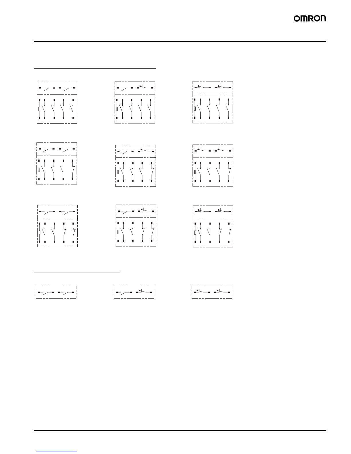
Connections
■Terminal Arrangement/Internal Connections
Relay with Auxiliary Contact Block
Auxiliary Contact Block
G7Z-4A-20Z G7Z-4A-11Z G7Z-4A-02Z
Note: The coil has no polarity. Note: The coil has no polarity. Note: The coil has no polarity.
G7Z-3A1B-20Z G7Z-3A1B-11Z G7Z-3A1B-02Z
Note: The coil has no polarity. Note: The coil has no polarity. Note: The coil has no polarity.
G7Z-2A2B-20Z G7Z-2A2B-11Z G7Z-2A2B-02Z
Note: The coil has no polarity. Note: The coil has no polarity. Note: The coil has no polarity.
53 54 63 64
7531A1
8642A2
53 54 61 62
7531A1
8642A2
51 52 61 62
7531A1
8642A2
53 54 63 64
21531A1
22642A2
21531A1
22642A2
53 54 61 62
21531A1
22642A2
51 52 61 62
53 54 63 64
211131A1
221242A2
211131A1
221242A2
53 54 61 62
211131A1
221242A2
51 52 61 62
G73Z-20Z G73Z-11Z G73Z-02Z
53 54 63 64
53 54 61 62
51 52 61 62
Page 7

8 Power Relays G7Z
Dimensions
Note: All units are in millimeters unless otherwise indicated.
Relay (12 VDC, 24 VDC) with Auxiliary Contact Block
Note: The dimensions are typical values.
Auxiliary Contact Block
Note: The dimensions are typical values.
DIN Track Mounting Height
(when using the PFP-100N or PFP-50N
mounting rail)
Note: The dimensions are typical values.
Application Examples
• Power supplies applied to Inverters and servo drivers for public and
industrial use
• Power supplies applied to uninterruptible power supplies plus
single- and three-phase power-supply switching for public and
industrial use
• Single- and three-phase power-supply switching of photovoltaic
power generation for public and industrial use
• Single- and three-phase power-supply switching of fuel cells for
public and industrial use
• Switching of heaters and motor for industrial use
75.5
60
51.5
62
45
47
Four, M3.5
Two, M3.5
84
92
70.7
15
Eight, M5
39±
0.2
Two, M4
4 Poles
Mounting Hole Dimensions
13
47
30
32.2
24.2
15
11
15.7
M3.5 × 4
88.3
96.3
15
75.0
64.3
Page 8

Power R elay s G7Z 9
Precautions
Be sure to read the common precautions provided in Best Control Devices Catalog Version 17 before using the Relay.
!WARNING
!CAUTION
■Precautions for Correct Use
Installation
• Mount the G7Z with the coil terminal at the top.
• Do not use the Relay with the terminal screw surfaces facing down.
• To mount the Relay, secure M4 screws in two locations.
Use a screw-tightening torque of 1.2 to 1.3 N·m.
• The Relay can be mounted directly on a mounting rail (PTP) or a
DIN Track (EN 50022-35
× 7.5, 15). The Relay cannot be mounted,
however, to some reinforced rails (e.g., those produced by Kameda
Denki or T oyogiken).
• Mount the Relay sideways when it is mounted on a rail.
• Use End Plates (PFP-M) on both sides of the Relay to make sure
that it is properly secured.
• Provide at least 5 mm of space between the sides and top of the
Relay and nearby grounded metal surfaces.
• Provide at least 30 mm of space between Relays when two or more
Relays are mounted in a row.
• The auxiliary contact block (G73Z) can be mounted on the Relay.
Mounting and Removal
Mounting
Insert the tab on the auxiliary contact
block into the groove on the Relay and
press down until the hook on the
auxiliary contact block catches in the
mounting hole on the Relay.
Removing
Slide the auxiliary contact block, remove
the auxiliary contact block tab from the
groove on the Relay, and remove the
auxiliary contact block hook from the
Relay.
Be careful not to apply excessive force
on the hook.
Take measures to prevent contact with charged parts
when using the Relay for high voltages.
Do not touch the terminal section (charged parts) when
power is being supplied.
Always use the Relay with terminal covers mounted.
Contact with charged parts may result in electric shock.
Do not touch the Relay when power is being su pplied or
right after the power has been turned OFF.
The hot surface may cause burn injury.
Up
Coil terminal
Terminal screw surface
Washer (external dia.: 7 max.)
39 mm
Up
DIN Track
(35 mm)
5 mm min
.
5 mm min.
5 mm min.
Grounded metal surface
30 mm min.
Tab
(1)
(2)
Hook
(2)
(1)
Tab
Hook
Page 9

10 Power Relays G7Z
Connecting
• Use round or open-end (Y-type) crimp terminals and connect the
terminals with the appropriate tightening torque. Refer to the
terminal section space in the following figure for the crimp terminal
dimensions.
Relay Contacts (Unit: mm)
Relay Coil
Auxiliary Contact Block
• One crimp terminal can be used for the Relay contact section (M5
screw). Two crimp terminals can be connected for the coil terminal
and auxiliary contact block.
Recommended Crimp Terminals and Wire
• Use the following tightening torque when tightening screws. Loose
screws may result in fire caused by abnormal heat generated when
the power is being supplied.
M5 screws: 2.0 to 2.2 N·m
M3.5 screws: 0.8 to 0.9 N·m
• Allow suitable slack on leads when wiring, and do not subject the
terminals to excessive force.
Microloads
The G7Z is used for switching power loads, such as current carry for
device power supplies and heater loads. Use an auxiliary contact
block (G73Z) if microloads are required for signal applicat ions and
operation status feedback.
Operating Coil
(Intern al Connectio ns of Coils)
DC Coil
• If a transistor drives the G7Z, check the leakage current and
connect a bleeder resistor if necessary.
• The must operate voltage is the minimum value for the Relay
armature to operate and the contacts to turn ON. Therefore,
fundamentally apply the rated voltage to the coils, taking into
consideration the increases in coil resistance caused by voltage
fluctuation and coil temperature rise.
Mirror Contact Mechanism
By combining a Relay with an auxiliary contact block, all NC contacts
of the auxiliary contact block will satisfy an impulse withstand voltage
of more than 2.5 kV or maintain a gap of more than 0.5 mm when the
coil is de-energized even if at least one NO contact (main contact) of
the Relay is welded (according to EN 60947-4-1).
Description of Mirror Contact Mechanism
Location Crimp
terminals
Appropriate wire size
Contact
section
5.5-5
2.63 to 6.64 mm
2
(AWG12, 10)
8-5
6.64 to 10.52 mm
2
(AWG8)
Coil
section
1.25-3.5
0.5 to 1.65 mm
2
(AWG20 to 16)
11
M5
14.5
12.5
6
6
6.8
4.3
M3.
5
9.5
6.8
5.5
5.5
M3.5
A2 A1
ab
Contact welding
NO NO NO
NCNC
NO
Auxiliary contact block
Relay
Impulse withstand voltage: 2.5 kV min. or
contact separation (a + b): 0.5 mm min.
Page 10

Power R elay s G7Z 11
Page 11

In the interest of product improvement, specifications are subject to change witho ut notic e.
ALL DIMENSIONS SHOWN ARE IN MILLIMETERS.
To convert millimeters into inches, multiply by 0.03937. To convert grams into ounces, multiply by 0.03527.
Cat. No. J160-E1-01
OMRON Corporation
Industrial Automation Company
Control Devices Division H.Q.
Industrial Components Department
Shiokoji Horikawa, Shimogyo-ku,
Kyoto, 600-8530 Japan
Tel: (81)75-344-7119/Fax: (81)75-344-7149
Regional Headquarters
OMRON EUROPE B.V.
Wegalaan 67-69, NL-2132 JD Hoofddorp
The Netherlands
Tel: (31)2356-81-300/Fax: (31)2356-81-388
OMRON ELECTRONICS LLC
1 East Commerce Drive, Schaumburg,
IL 60173 U.S.A.
Tel: (1)847-843-7900/Fax: (1)847-843-8568
OMRON ASIA PACIFIC PTE. LTD.
83 Clemenceau Avenue,
#11-01, UE Square,
239920 Singapore
Tel: (65)6835-3011/Fax: (65)6835-2711
OMRON (CHINA) CO., LTD.
Room 2211, Bank of China Tower,
200 Yin Cheng Road (M),
Shanghai, 200120 China
Tel: (86)21-5037-2222/Fax: (86)21-5037-2200
0306
Warranty and Application Considerations
Read and Understand this Catalog
Please read and understand this catalog before purchasing the products. Please consult your OMRON representative if you have any
questions or comme nt s.
Warranty and Limitations of Liability
WARRANTY
OMRON's exclusive warranty is that the products are free from defects in materials and workmanship for a period of one year (or other
period if specified) from dat e of sale by OMRON.
OMRON MAKES NO WARRANTY OR REPRESENTATION, EXPRESS OR IMPLIED, REGARDING NON-INFRINGEMENT,
MERCHANT ABILITY, OR FITNESS FOR PARTICULAR PURPOSE OF THE PRODUCTS. ANY BUYER OR USER ACKNOWLEDGES
THAT THE BUYER OR USER ALONE HAS DETERMINED THAT THE PRODUCTS WILL SUITABLY MEET THE REQUIREMENTS
OF THEIR INTENDED USE. OMRON DISCLAIMS ALL OTHER WARRANTIES, EXPRESS OR IMPLIED.
LIMITATIONS OF LIABILITY
OMRON SHALL NOT BE RESPONSIBLE FOR SPECIAL, INDIRECT, OR CONSEQUENTIAL DAMAGES, LOSS OF PROFITS, OR
COMMERCIAL LOSS IN ANY WAY CONNECTED WITH THE PRODUCTS, WHETHER SUCH CLAIM IS BASED ON CONTRACT,
WARRANTY, NEGLIGENCE, OR STRICT LIABILITY.
In no event shall the responsibility of OMRON for any act exceed the individual price of the product on which liability is asserted.
IN NO EVENT SHALL OMRON BE RESPONSIBLE FOR WARRANTY , REPAIR, OR OTHER CLAIMS REGARDING THE PRODUCTS
UNLESS OMRON'S ANALYSIS CONFIRMS THAT THE PRODUCTS WERE PROPERLY HANDLED, STORED, INSTAL LED, AND
MAINTAINED AND NOT SUBJECT TO CONTAMINATION, ABUSE, MISUSE, OR INAPPROPRIATE MODIFICATION OR REPAIR.
Application Considerations
SUITABILITY FOR USE
OMRON shall not be responsible for conformity wit h any standards, codes, or regulations that apply to the com b ination of products in
the customer's applicat i on or use of the products.
Take all necessary steps to determine the suitability of the product for the syste ms, machines, and equipment with which it will b e us ed .
Know and observe all prohibitions of use applicable to this product.
NEVER USE THE PRODUCTS FOR AN APPLICA TION INV OL VING SERIOUS RISK TO LIFE OR PROPER TY WITHOUT ENSURING
THAT THE SYSTEM AS A WHOLE HAS BEEN DESIGNED TO ADDRESS THE RISKS, AND THAT THE OMRON PRODUCTS ARE
PROPERLY RATED AND INSTALLED FOR THE INTENDED USE WITHIN THE OVERALL EQUIPMENT OR SYSTEM.
Disclaimers
PERFORMANCE DATA
Performance data given in this catalog is provided as a guide for the user in determining suitability and does not constitute a warranty.
It may represent the result of OMRON's te st conditions, and the users must correlate it to a ct ual application requirements. Actual
performance is subject to th e O M RON Warranty and Limitations of Liability.
CHANGE IN SPECIFICATIONS
Product specifications and accessories may be changed a t any time based on improvements and other reasons. Consult with your
OMRON representative at any time to conf i rm actual specifications of pu rc hased product.
DIMENSIONS AND WEIGHTS
Dimensions and weights are nominal and are not to be used for manufacturing purposes, even when tolerances are shown.
 Loading...