

Page 1
1
G7S Safety Relay G7S
Safety Relay conforming to EN standard
Conforms to prEN50205.
A minimum of 0.5 mm between contacts even when
one contact is welded. (prEN50205 Class A)
Forcibly guided contacts.
The G7S contributes to the protection of machinery
when used as part of an interlocking circuit.
Most suitable for safety circuits in press machinery,
machine tools, and other production machinery.
CE mark (EC Low-voltage Directive 73/23/EEC)
Track-mounting and Back-mounting Sockets are
available.
Note: Be sure to refer to the Precautions on page 7.
Ordering Information
Model Number Legend
G7S-jAjB
12
1. NO Contact Poles
4: 4PST-NO
3: 3PST-NO
2. NC Contact Poles
2: DPST-NC
3: 3PST-NC
Safety Relays
Type
Poles Contact form Rated voltage (V) Model
Standard 6 poles
4PST-NO, DPST-NC
24 VDC
G7S-4A2B
3PST-NO, 3PST-NC G7S-3A3B
Accessories
Safety Relay Sockets
Type
Model
Track-mounting Common for track mounting
and screw mounting
P7S-14F
Back-mounting
Solder terminals P7S-14A
PCB terminals P7S-14P
Socket Mounting Plate
Applicable Socket
Quantity Model
P7S-14A 10 P7S-A10
Relay Removal Tool
Applicable Sockets
Model
P7S-14F
P7S-14A
P7S-14P
P7S-B
Page 2
G7S
G7S
2
Specifications
Ratings
Operation Coil
Rated voltage Rated current Coil resistance Must operate
voltage
Must release
voltage
Max. voltage Power
consumption
24 VDC 30 mA 800 Ω 80% max. (V) 10% min. (V) 110% (V) Approx. 0.8 W
Note: 1. The rated current and coil resistance are measured at a coil temperature of 23°C with tolerances of ±15%.
2. Performance characteristics are based on a coil temperature of 23°C
3. The maximum voltage is based on an ambient operating temperature of 23°C maximum.
Switching Section (Contact Ratings)
Load Resistive load (cos φ =1) Inductive load (cos φ = 0.4, L/R = 7 ms)
Rated load 240 VAC: 3 A, 24 VDC: 3 A 240 VAC: 3 A, 24 VDC: 1 A
Rated carry current 6 A
Maximum switching voltage 250 VAC, 24 VDC
Maximum switching current 6 A
Maximum switching capacity (reference
value)
1,440 VA, 144 W
Min. permissible load
(See note.)
5 VDC, 10 mA
Contact material Ag ) Au
Note: The above values are based on an operating frequency of 60 operations/min.
Characteristics
Contact resistance (See note 2.) 100 mΩ max.
Operate time (See note 3.) 50 ms max.
Release time (See note 3.) 50 ms max.
Maximum operating
Mechanical 18,000 operations/hr
frequency
Rated load 1,800 operations/hr
Insulation resistance 100 MΩ min. (at 500 VDC)
Dielectric strength 2,500 VAC, 50/60 Hz for 1 min (1,500 VAC between contacts of same polarity)
Vibration
Destruction 10 to 55 Hz, 1.5-mm double amplitude
Malfunction 10 to 55 Hz, 0.75-mm double amplitude
Shock
Destruction 1,000 m/s2 (approx. 100G)
Malfunction 100 m/s2 (approx. 10G)
Life expectancy
Mechanical 10,000,000 operations min. (at approx. 18,000 operations/hr)
Electrical 100,000 operations min. (at the rated load and approx. 1,800 operations/hr)
Ambient operating temperature –10°C to 70°C (no icing)
Ambient operating humidity 35% to 85% RH
Ambient storage temperature –25°C to 70°C (no icing)
Ambient storage humidity 35% to 85% RH
Weight Approx. 65 g
Note: 1. The values given above are initial values.
2. Measurement conditions: 5 VDC, 10 mA, voltage drops.
3. Measurement conditions:
Rated voltage operation
Ambient operating temperature: 23°C
Does not include bounce time.
Characteristics of Safety Relay Socket
Model Continuous current Dielectric strength Insulation resistance
P7S-14j
6 A 2000 VAC for 1 min. between terminals 1000 MΩ min. (see note)
Note: Measurement conditions: Measurement of the same points as for the dielectric strength at 500 VDC.
Page 3
G7S
G7S
3
Approved Standards
VDE0435 (Electrical Relays); Approved by VDE
IEC255 (Electrical Relays); Approved by VDE
prEN50205 (Electrical Relays); Approved by VDE
UL508 (Industrial Control Device); Pending
CSA22.2 No.14 (Industrial Control Device); Pending
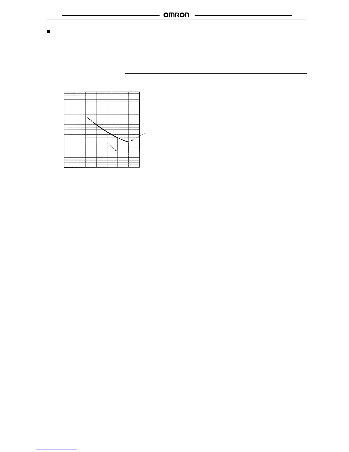
Engineering Data
100
Life expectancy (x10 operations)
10
1
0
123456
G7S
G9S
Life Expectancy (240 VAC; cosφ=0.4, cosφ=1)
Switching current (A)
I (Current)
4
Life Expectancy (AC15, DC13 IEC947-5-1/Table 4)
6,050 operations min. (AC15, 240 VAC, 3 A, cosφ=0.3)
6,050 operations min. (DC13, 24 VDC, 1 A, L/R 100 ms)
VDE approved.
Page 4

G7S
G7S
4
Dimensions
Note: All units are in millimeters unless otherwise indicated.
Safety Relays
G7S-4A2B
G7S-3A3B
Terminal Installation/Internal
Connection Diagram
(Bottom View)
G7S-4A2B
Cross-section of
Mounting Holes
G7S-3A3B
62 max.
22.5 max.
37 max.
5 min.
24 VDC
24 VDC
Fourteen,
1.8 dia.
Safety Relay Sockets
P7S-14F Track-mounting Socket
Terminal Installation/Internal
Connection Diagram
(Top View)
40 max.
90.5 max.
69 max.
47 max.
40 max.
47 max.
Cross-section of
Mounting Holes
With Safety Relay Mounted
7.5
4
31.3
7 x 4 = 28
Page 5

G7S
G7S
5
P7S-14A Back-mounting Socket
(Solder Terminals)
61.5 max.
23 max.
33 max.
39 max.
Terminal Installation/Internal
Connection Diagram
(Bottom View)
G7S-4A2B
G7S-3A3B
With Safety Relay Mounted
Cross-section of
Mounting Holes
P7S-14P Back-mounting Socket
(PCB Terminals)
Terminal Installation/Internal
Connection Diagram
(Bottom View)
G7S-4A2B
Cross-section of
Mounting Holes
G7S-3A3B
23 max.
61.5 max.
23 max.
29 max.
With Safety Relay Mounted
28 max.
Two, 6.5 dia x 7.9 deep
Fourteen, 1.8 dia.
Two,
3.6 dia.
Page 6

G7S
G7S
6
Socket Mounting Plate
P7S-A10 (Special Mounting Plate for P7S-14A)
261 max.
81 max.
Four, C0.5
Relay Removal Tool
P7S-B
Page 7

G7S
G7S
7
Precautions
Forcibly Guided Contacts
When NO contacts are welded, the coil will be non-energized so all NC contacts will maintain a distance between the contacts of 0.5 mm minimum. Likewise if NC contacts are welded, the coil will be energized so all contacts will maintain a distance between each other of 0.5 mm
minimum.
Application
Caution
Do not touch the terminal area of the Relays or the socket terminal area (charged area) while power is ON. Electric shock
will result.
Safety Relays
A Safety Relay is a Relay with which a safety circuit can be configured. For common precautions when using and handling Relays, refer to OMRON’s Relay Catalog.
Contacts
The coil terminals have polarity (positive and negative).Operation is
not possible if these are connected in reverse.
!
Page 8

G7S
G7S
8
OMRON Corporation
Control Components Division H.Q.
28th Fl., Crystal Tower Bldg.
1-2-27, Shiromi, Chuo-ku,
Osaka 540 Japan
Phone: 06-949-6115 Fax: 06-949-6134
ALL DIMENSIONS SHOWN ARE IN MILLIMETERS.
To convert millimeters into inches, multiply by 0.03937. To convert grams into ounces, multiply by 0.03527.
Cat. No. J107-E1-2 In the interest of product improvement, specifications are subject to change without notice.
Printed in Japan
0897-1M (1296) a
 Loading...