

Page 1
1
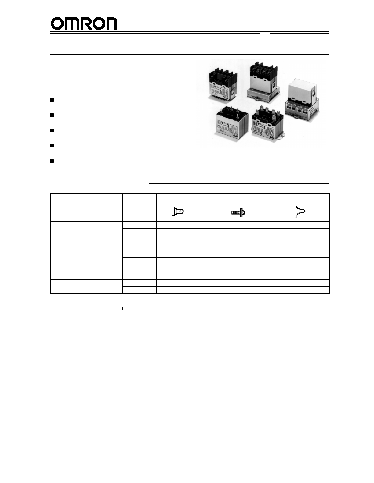
Power Relay G7L
A High-capacity,
High-dielectric-strength Relay
Compatible with Momentary Voltage
Drops
No contact chattering for momentary voltage drops
up to 50% of rated voltage.
Wide-range AC-activated coil that handles 100 to
120 or 200 to 240 VAC at either 50 or 60 Hz.
Miniature hinge for maximum switching power,
particularly for inductive loads.
Flame-resistance materials (UL94V-0-qualifying)
used for all insulation material.
Quick-connect, screw,andPCBterminals, and DIN
track mounting available.
R
CE
Ordering Information
Mounting type Contact form
Quick-connect
terminals
Screw terminals
PCB
terminals
E-bracket
SPST-NO G7L-1A-T G7L-1A-B --DPST-NO G7L-2A-T G7L-2A-B ---
E-bracket (with test button)
SPST-NO G7L-1A-TJ G7L-1A-BJ --DPST-NO G7L-2A-TJ G7L-2A-BJ ---
Upper bracket
SPST-NO G7L-1A-TUB G7L-1A-BUB --DPST-NO G7L-2A-TUB G7L-2A-BUB ---
Upper bracket
SPST-NO G7L-1A-TUBJ G7L-1A-BUBJ ---
(with test button)
DPST-NO G7L-2A-TUBJ G7L-2A-BUBJ ---
PCB mounting
SPST-NO --- --- G7L-1A-P
DPST-NO --- --- G7L-2A-P
Rated coil voltage
Note:
1. When ordering, add the rated coil voltage to the model number.
Example: G7L-1A-T 12 V AC(~)
Page 2
G7L
G7L
2
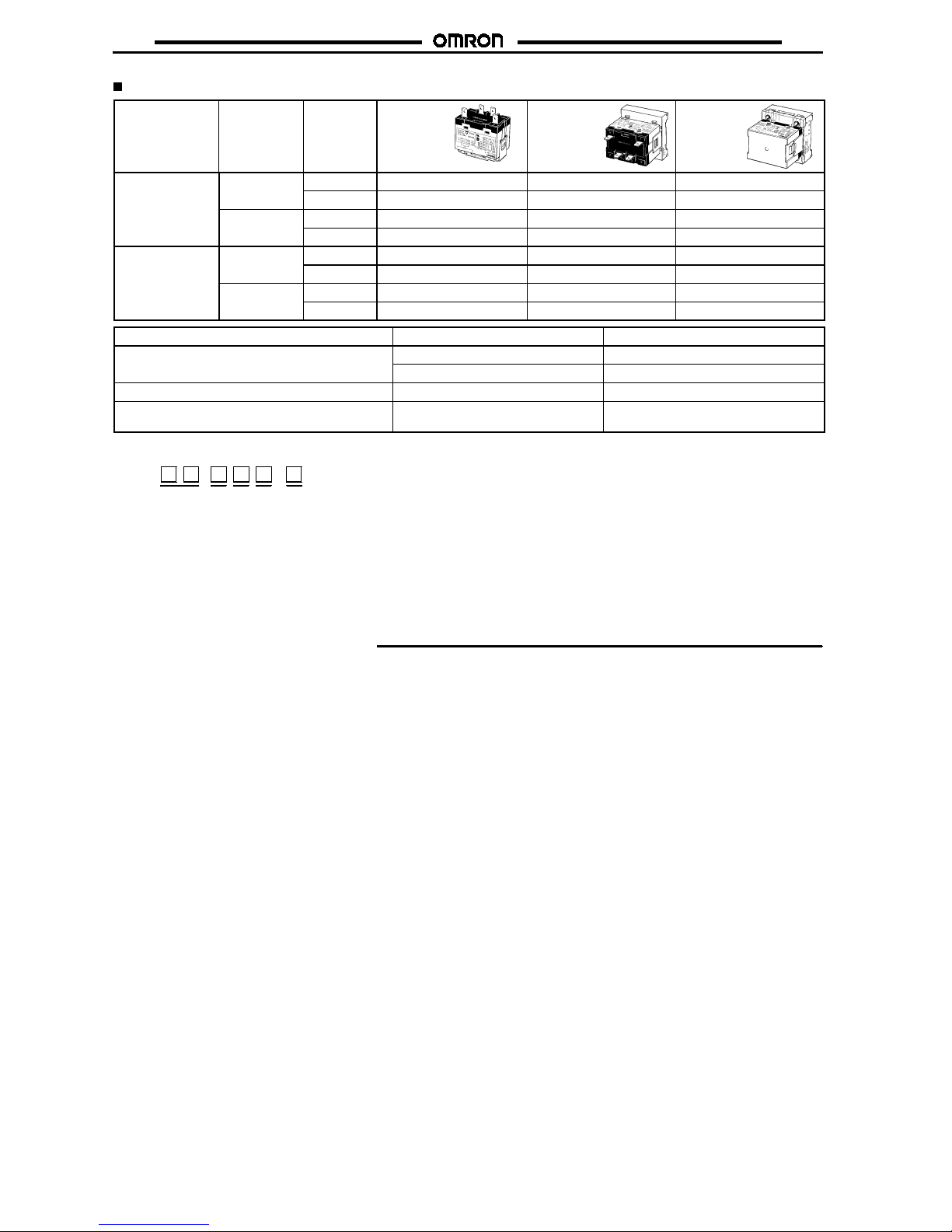
Accessories (Order Separately)
Terminals Contact form Model R99-07
E-brackets
P7LF-D DIN
Track
Mounting
Adapter
P7LF-06
Front-con
necting
Socket
Quick-connect
SPST-NO G7L-1A-T Yes Yes Yes
terminals
G7L-1A-TJ Yes Yes Yes
DPST-NO G7L-2A-T Yes Yes Yes
G7L-2A-TJ Yes Yes Yes
Screw terminals
SPST-NO G7L-1A-B Yes Yes No
G7L-1A-BJ Yes Yes No
DPST-NO G7L-2A-B Yes Yes No
G7L-2A-BJ Yes Yes No
Applicable Relay Name Model
G7L-1A-T/G7L-1A-TJ/G7L-1A-B/G7L-1A-BJ E-bracket R99-07
G7L-2A-T/G7L-2A-TJ/G7L-2A-B/G7L-2A-BJ Adapter P7LF-D
G7L-1A-T/G7L-1A-TJ/G7L-2A-T/G7L-2A-TJ Front-connecting Socket P7LF-06
G7L-1A-B/G7L-1A-BJ/G7L-1A-BUB/G7L-1A-BUBJ
G7L-2A-B/G7L-2A-BJ/G7L-2A-BUB/G7L-2A-BUBJ
Cover P7LF-C
Model Number Legend
G7L - -
1234,5
1. Contact Form
1A: SPST-NO
2A: DPST-NO
2. Terminal Shape
T: Quick-connect terminals
P: PCB terminals
B: Screw terminals
3. Mounting Construction
Blank: E-bracket
UB: Upper bracket
4. Special Functions
Blank: Standard mode
J: With test button
5. Rated Coil Voltage
AC: 12, 24, 50, 100 to 120, 200 to 240
DC: 6, 12, 24, 48, 100
Application Examples
!
Compressors for air conditioners and heater switching
controllers.
!
Switching controllers for power tools or motors.
!
Power controllers for water heaters.
!
Power controllers for dryers.
!
Lamp controls, motor drivers, and power supply switching in
copymachines,facsimilemachines, andotherofficeequipment.
!
Lighting controllers.
!
Power controllers for packers or food processing equipment.
!
Magnetron control in microwaves.
Page 3

G7L
G7L
3
Specifications
Coil Ratings
Rated voltage Rated
current
Coil resistance Must operate
voltage
Must release
voltage
Max. voltage Power
consumption
(approx.)
AC (~)
12 V 142 mA ---
75% max. of
15% min. of
110% of rated
1.7to2.5VA
(
)
24 V 71 mA ---
rated voltage rated voltage voltage (60 Hz)
50 V 34 mA --100 to 120 V 17.0 to
20.4 mA
--- 75 V 18 V 132 V
200 to 240 V 8.5 to 10.2 mA --- 150 V 36 V 264 v
DC (=)
6V 317 mA 18.9
"
75% max. of
15% min. of
110% of rated
1.9 W
(
)
12 V 158 mA 75
"
rated voltage rated voltage voltage
24 V 79 mA 303
"
48 V 40 mA 1220
"
100 V 19 mA 5260
"
Note:
1. Theratedcurrentand coilresistancearemeasured atacoil temperatureof23#Cwithtolerancesof+15%/--20%for ACratedcurrent
and$15% for DC coil resistance.
2. Performance characteristic data are measured at a coil temperature of 23#C.
3.~indicates AC and=indicates DC (IEC417 publications).
Contact Ratings
Model
G7L-1A-Tj/G7L-1A-B
j
G7L-2A-Tj/G7L-2A-B
j
G7L-1A-P/G7L-2A-P
Resistive load
(cos%=1)
Inductive load
(cos%=0.4)
Resistive load
(cos%=1)
Inductive load
(cos%=0.4)
Resistive load
(cos%=1)
Inductive load
(cos%=0.4)
Rated load
30 A, 220 VAC
(
~
)
25 A, 220 VAC
(
~
)
25 A, 220 VAC
(
~
) 20 A, 220 VAC
(
~
)
Rated carry
current
30 A 25 A 20 A
Max. switching
voltage
250 VAC
(
~
)
Max. switching
current
30 A 25 A 20 A
Max. switching
power
6,600 VAC
(
~
) 5,500 VAC
(
~
) 5,500 VAC
(
~
) 4,400 VAC
(
~
)
Min. permissible
load*
100 mA, 5 VDC
(
=
)
*Note:
P level:
&
60
=0.1x10⁻⁶/operation
Page 4
G7L
G7L
4
Characteristics
Contact resistance
50 m"max.
Operate time
30 ms max.
Release time
30 ms max.
Max. operating frequency
Mechanical: 1,800 operations/hr
Electrical: 1,800 operations/hr (under rated load)
Insulation resistance
1,000 M"min. (at 500 VDC)
Dielectric strength
4,000 VAC min., 50/60 Hz for 1 min between coil and contacts
2,000 VAC, 50/60 Hz for 1 min between contacts of same polarity
2,000 VAC, 50/60 Hz for 1 min between contacts of different polarity (DPST-NO model)
Impulse withstand voltage
10,000 V between coil and contact (with 1.2 x 50's impulse wave)
Vibration resistance
Destruction: 10 to 55 Hz, 1.5-mm double amplitude
Malfunction: 10 to 55 Hz, 1.5-mm double amplitude
Shock resistance
Destruction: 1,000 m/s
2
Malfunction: 100 m/s
2
Life expectancy
Mechanical:1,000,000 operations min. (at 1,800 operations/hr)
Electrical: 100,000 operations min. (at 1,800 operations/hr under rated load)
Ambient temperature
Operating: --25#Cto60#C (with no icing)
Ambient humidity
Operating: 35% to 85%
Weight
Quick-connect terminal models: approx. 90 g
PCB terminal models: approx. 100 g
Screw terminal models: approx. 120 g
Note:
The values given above are initial values.
Page 5
G7L
G7L
5
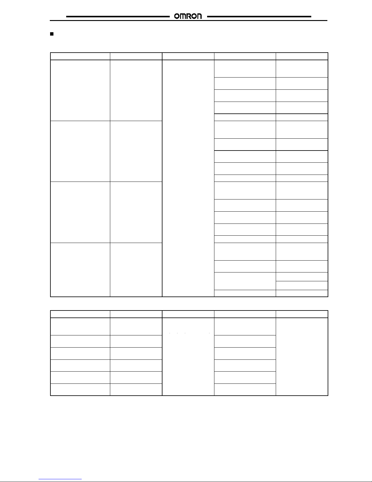
Approved by Standards
UL 508, 1950 Recognitions (File No. E41643)
CSA 22.2 No.14 Listings (File No.LR35535)
Model Contact Form Coil ratings Contact ratings Operations
G7L-1A-T
j
G7L-1A-B
j
SPST-NO 12 to 240 VAC
5to220VDC
30 A, 277 VAC (RES)
25 A, 277 VAC (GEN)
30 A, 120 VAC (GEN)
100 x 10
3
1.5 kW, 120 VAC (T)
1.5 HP, 120 VAC
6x10
3
3 HP, 277 VAC 100 x 10
3
(CSA; 6 x 10³)
20 FLA/120 LRA, 120 VAC
17 FLA/102 LRA, 265 VAC
30 x 10
3
TV-10, 120 VAC 25 x 10
3
G7L-2A-T
j
G7L-2A-B
j
DPST-NO
25 A, 277 VAC (RES)
25 A, 277 VAC (GEN)
25 A, 120 VAC (GEN)
100 x 10
3
1.3 kW, 120 VAC (T)
1 HP, 120 VAC
6x10
3
2 HP, 277 VAC 100 x 10
3
(CSA; 6 x 10³)
20 FLA/120 LRA, 120 VAC
17 FLA/102 LRA, 265 VAC
30 x 10
3
TV-8, 120 VAC 25 x 10
3
G7L-1A-P SPST-NO
20 A, 277 VAC (RES)
20 A, 277 VAC (GEN)
20 A, 120 VAC (GEN)
100 x 10
3
1.5 kW, 120 VAC (T)
1.5 HP, 120 VAC
6x10
3
3 HP, 277 VAC 100 x 10
3
(CSA; 6 x 10³)
20 FLA/120 LRA, 120 VAC
17 FLA/102 LRA, 265 VAC
30 x 10
3
TV-10, 120 VAC 25 x 10
3
G7L-2A-P DPST-NO
20 A, 277 VAC (RES)
20 A, 277 VAC (GEN)
20 A, 120 VAC (GEN)
100 x 10
3
1.3 kW, 120 VAC (T)
1 HP, 120 VAC
6x10
3
2 HP, 277 VAC
100 x 10
3
20
FLA
/
120
LRA
, 120
VAC
17 FLA/102 LRA, 265 VAC
30 x 10
3
TV-8, 120 VAC 25 x 10
3
TÜV: File No. R9051158 (VDE 0435, IEC 255, IEC 950, EN60950)
Model Contact Form Coil ratings Contact ratings Operations
G7L-1A-B
j
SPST-NO
6, 12, 24, 48, 100, 110,
200, 220 VDC
12, 24, 50, 100 to 120,
30 A, 240 VAC (cos%=1.0)
25 A, 240 VAC (cos%=0.4)
30 A, 120 VAC (cos%=0.4)
100 x 10
3
G7L-2A-B
j
DPST-NO
,,,
,
200 to 240 VAC
25 A, 240 VAC (cos%=1.0)
25 A, 240 VAC (cos%=0.4)
G7L-1A-T
j
SPST-NO 25 A, 240 VAC (cos%=1.0)
25 A, 240 VAC (cos%=0.4)
G7L-2A-T
j
DPST-NO 25 A, 240 VAC (cos%=1.0)
25 A, 240 VAC (cos%=0.4)
G7L-1A-P SPST-NO 20 A, 240 VAC (cos%=1.0)
20 A, 240 VAC (cos%=0.4)
G7L-2A-P DPST-NO 20 A, 240 VAC (cos%=1.0)
20 A, 240 VAC (cos%=0.4)
Page 6

G7L
G7L
6
Engineering Data
G7L-1A-T/G7L-1A-B
Maximum Switching Power
Switching voltage (V)
Switching current (A)
Life Expectancy
Switching current (A)
AC resistiveload
AC inductiveload
(cos%=0.4)
220 VAC resistiveload
220 VAC
inductive load
(cos%=0.4)
Life expectancy (x10 operations)
3
G7L-2A-T/G7L-2A-B
Maximum Switching Power
Switching voltage (V)
Life Expectancy
Switching current (A)
G7L-1A-P/G7L-2A-P
Maximum Switching Power
Switching voltage (V)
Life Expectancy
Switching current (A)
Switching current (A)Switching current (A)
AC resistiveload
AC inductiveload
(cos%=0.4)
AC resistiveload
AC inductiveload
(cos%=0.4)
220 VAC resistiveload
220 VAC resistiveload
220 VAC
inductive load
(cos%=0.4)
220 VAC
inductive load
(cos%=0.4)
Life expectancy (x10 operations)
3
Life expectancy (x10 operations)
3
Page 7

G7L
G7L
7
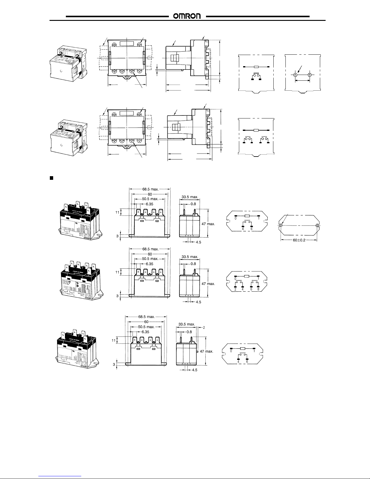
Dimensions
Note:
1. All units are in millimeters unless otherwise indicated.
2. E-brackets are sold separately.
Quick-connect Terminals with E-bracket
G7L-1A-T
G7L-2A-T
Terminal Arrangement/
Internal Connections
(Top View)
Mounting Holes
G7L-1A-TJ
with Test Button
G7L-2A-TJ
with Test Button
Two, 4.5-dia. hole or
M4 tappedholes
Quick-connect Terminals with DIN Track Mounting Adapter
Note:
1. The DIN Track Mounting Adapter and DIN tracks are sold separately.
2. The DIN Track Mounting Adapter can be track-mounted or screw-mounted.
G7L-1A-T
Terminal Arrangement/
Internal Connections
(Top View)
Mounting Holes
01
46
40$0.1
Two, M4 or
4.5-dia. holes
PFP-jN
55.5 max. 63 max.
66.5 max.
51.5 max.
G7L
P7LF-D
5
Page 8

G7L
G7L
8
G7L-2A-T
Terminal Arrangement/
Internal Connections
(Top View)
Mounting Holes
01
24 68
40$0.1
Two, M4 or
4.5-dia. holes
55.5 max.
63 max.
66.5 max.
51.5 max.
5
PFP-jN
G7L
P7LF-D
01
46
G7L-1A-TJ
with Test Button
G7L-2A-TJ
with Test Button
PFP-jN
55.5 max.
63 max.
66.5 max.
51.5 max.
G7L
P7LF-D
2
5
55.5 max.
63 max.
66.5 max.
51.5 max.
2
5
PFP-jN
G7L
P7LF-D
01
24 68
Quick-connect Terminals with Front-connecting Socket
Note:
1. The Front-connecting Socket and DIN tracks are sold separately.
2. The Front-connecting Socket can be track-mounted or screw-mounted.
G7L-1A-T
Terminal Arrangement/
Internal Connections
(Top View)
Mounting Holes
40$0.1
Two, M4 or
4.5-dia. holes
01
46
G7L-2A-T
01
24 68
65 max.
61.5 max.
51.5 max.
5
G7L
P7LF-06
55.5 max.
65 max.
61.5 max.
51.5 max.
5
Two, M3.5 screws
for coil
Four, M4 screws
for contact
PFP-jN
G7L
P7LF-06
55.5 max.
Two, M3.5 screws
for coil
Four, M4 screws
for contact
PFP-jN
Page 9
G7L
G7L
9
G7L-1A-TJ
with Test Button
G7L-2A-TJ
with Test Button
Terminal Arrangement/
Internal Connections
(Top View)
Mounting Holes
40$0.1
Two, M4 or
4.5-dia. holes
01
46
01
24 68
55.5 max.
65 max.
61.5 max.
51.5 max.
5
2
Two, M3.5 screws
for coil
Two, M4 screws
for contact
PFP-jN
G7L
P7LF-06
Two, M3.5 screws
for coil
Four, M4 screws
for contact
55.5 max.
65 max.
61.5 max.
51.5 max.
5
2
PFP-jN
G7L
P7LF-06
Quick-connect Terminals with Upper Bracket
G7L-1A-TUB
G7L-2A-TUB
Terminal Arrangement/
Internal Connections
(Top View)
Terminal Arrangement/
Internal Connections
(Top View)
Mounting Holes
Two, 4.5-dia. hole or
M4 tappedholes
G7L-1A-TUBJ
with Test Button
Terminal Arrangement/
Internal Connections
(Top View)
Page 10

G7L
G7L
10
G7L-2A-TUBJ
with Test Button
Mounting HolesTerminal Arrangement/
Internal Connections
(Top View)
Two, 4.5-dia. hole or
M4 tappedholes
Screw Terminals with E-bracket
Note:
E-brackets are sold separately.
G7L-1A-B
G7L-2A-B
G7L-1A-BJ
with Test Button
G7L-2A-BJ
with Test Button
Terminal Arrangement/
Internal Connections
(Top View)
Mounting Holes
Two, M3.5 screws
for coil
Two, M3.5 screws
for coil
Two, M3.5 screws
for coil
Two, M3.5 screws
for coil
Two, M4 screws
for contact
Four, M4 screws
for contact
Two, M4 screws
for contact
Four, M4 screws
for contact
Two, 4.5-dia. hole
or M4tapped holes
Page 11

G7L
G7L
11
Screw Terminals with DIN Track Mounting Adapter
Note:
1. The DIN Track Mounting Adapter and DIN tracks are sold separately.
2. The DIN Track Mounting Adapter can be track-mounted or screw-mounted.
G7L-1A-B
G7L-2A-B
Terminal Arrangement/
Internal Connections
(Top View)
Mounting Holes
40$0.1
Two, M4 or
4.5-dia. holes
01
46
01
24 68
55.5 max.
69 max.
65.5 max.
51.5 max.
5
PFP-jN
G7L
P7LF-D
55.5 max.
69 max.
65.5 max.
51.5 max.
5
PFP-jN
G7L
P7LF-D
G7L-1A-BJ
with Test Button
G7L-2A-BJ
with Test Button
01
46
01
24 68
55.5 max.
69 max.
65.5 max.
51.5 max.
5
PFP-jN
G7L
P7LF-D
2
55.5 max.
69 max.
65.5 max.
51.5 max.
5
2
PFP-jN
G7L
P7LF-D
Screw Terminals with Upper Bracket
G7L-1A-BUB
Terminal Arrangement/
Internal Connections
(Top View)
Two, M3.5 screws
for coil
Two, M4 screws
for contact
Mounting Holes
Two, 4.5-dia. hole
or M4tapped holes
Page 12

G7L
G7L
12
G7L-2A-BUB
G7L-1A-BUBJ
with Test Button
G7L-2A-BUBJ
with Test Button
Mounting Holes
Terminal Arrangement/
Internal Connections
(Top View)
Terminal Arrangement/
Internal Connections
(Top View)
Terminal Arrangement/
Internal Connections
(Top View)
Two, M3.5 screws
for coil
Four, M4 screws
for contact
Two, M3.5 screws
for coil
Two, M3.5 screws
for coil
Two, M4 screws
for contact
Four, M4 screws
for contact
Two, 4.5-dia. hole
or M4tapped holes
PCB Terminals with PCB Mounting
G7L-1A-P
G7L-2A-P
Terminal Arrangement/
Internal Connections
(Top View)
Terminal Arrangement/
Internal Connections
(Top View)
Mounting Holes
(Bottom View)
Mounting Holes
(Bottom View)
Page 13

G7L
G7L
13
R99-07G5D
E-bracket
P7LF-D Adapter
Mounting Holes
(Bottom View)
P7LF-06
Front-connecting
Socket
P7LF-C Cover
Put the P7LF-C cover onto the terminals in order
to protect the user from electric shock.
40$0.1
Two, M4 or
4.5-dia. holes
40$0.1
Two, M4 or
4.5-dia. holes
26 24 17.8
40
46
30
24
7
50
55
10
19.7
4.4
3
Two, 4.5-dia.
holes
25
Two, M3.5 screws
for coil
40$0.1
55.5 max.
46 max.
51.5 max.
5
35.2 max.
9.2
Four, M4 screws
for contact
8
55.5 max.
51.5 max.
5
14.5
40$0.1
Mounting Holes
(Bottom View)
34.5 max.
50.5 max.
1
6max.
40$0.1
Two, M4 or
4.5-dia. holes
Mounting Holes
(Bottom View)
Internal Coil Circuit
DC Operating Coil AC Operating Coil
Page 14

G7L
G7L
14
Precautions
Refer to page NO TAG for general precautions.
Handling
!
To preserve performance, do not drop orotherwise subject the
Power Relay to shock.
!
Thecaseis notdesignedto beremovedduring normalhandling
and operation. Doing so may affect performance.
!
Use the Power Relay in a dry environment free from excessive
dust, SO
2,H2
S, or organic gas.
!
Do notallowa voltage greater thanthemaximum allowable coil
voltage to be applied continuously.
!
Do not use the Power Relay outside of specified voltages and
currents.
!
Do not allow the ambient operating temperature to exceed the
specified limit.
Installation
!
Although there are not specific limits on the installation site, it
should be as dry and dust-free as possible.
!
PCB Terminal-equipped Relays weighapproximately100g. Be
sure that the PCB is strong enough to support them. We
recommend dual-side through-hole PCBs to reduce solder
cracking from heat stress.
!
Quick-connectterminalscanbeconnectedtoFastonreceptacle
#250 and positive-lock connectors.
!
Allowsuitableslackonleadswhenwiring, anddo notsubject the
terminals to excessiveforce.
Cleaning PCB Terminals
!
PCB terminals have flux-tight construction which prevents flux
from penetrating into the Relay base housing, e.g., due to
capillaryactionupthe terminalswhenRelay issolderedonto the
PCB. This type of Relay cannot be immersed for cleaning.
Connecting
!
Refer to the following table when connecting a wire with a
crimp-style terminal to the G7L.
Terminals
Screw terminals Front-connecting
Socket
Coil
8
5.8
5
M3.5
8
6.5
5.3
M3.5
Contact
5.5
6.5
9.2
M4
7
5.5
9.2
M4
Rated Current Flow
When using B-series (screw) products, the rated current from the
screw terminals (M4) should be 20 A or less according to jet standard (electrical appliance and material control law of Japan).
Operating Coil
!
As a rule, either a DC battery or a DC power supply with a
maximumof5%ripplemust beused forthe operatingvoltagefor
DC Relays. Before using arectifiedACsupply, confirm that the
rippleisnotgreaterthan 5%.Ripple greaterthanthis canleadto
variations in the operating and reset voltages.
As excessive ripple can generate pulses, the insertion of a
smoothing capacitor is recommended as shown below.
Emax
.: Max. ripple
Emin.
: Min. ripple
E mean
: Mean DC value
Smoothing
capacitor
Relay
Ripple
Emin.Emax. Emean
DC fraction
% of ripple = x 100
Emax.--E
min.
E mean
!
When driving a transistor, check the leakage current and
connect a bleeder resistor if necessary.
DIN Track Mounting Adapter and
Front-connecting Socket
DIN Track Mounting
!
Use a DIN-conforming 50-cm track or 1-m track (both are sold
separately) for mounting a number of G7L Relays.
Cut and shorten the track to an appropriate length it if the
required track length is less than 50 cm.
!
The DIN TrackMounting Adapter andFront-connectingSocket
can bemountedon the G7Lwithjust one handanddismounted
with ease by using a screwdriver.
!
To support the G7Lmountedona DIN Track Mounting Adapter
or Front-connecting Socket, use the PFP-M End Plate. Put the
End Plate onto the DIN Track Mounting Adapter or
Front-connecting Socket so that the surface mark of the End
Plate faces upwards. Then tighten the screw of the End Plate
securely with a screwdriver.
Screw Mounting
!
Screw-mountthe DINTrackMountingAdapterorFront-connecting Socket securely after opening screw mounting holes on
them.
!
When cutting or opening holes on the panel after the
Front-connecting Socket is mounted, take proper measures so
that thecuttingchipswill notfallonto theRelay terminals.When
cutting oropening holeson theupper partof thepanel, maskthe
Front-connecting Socket properly with a cover.
ALL DIMENSIONS SHOWN ARE IN MILLIMETERS.
To convert millimeters into inches, multiply by 0.03937. To convert grams into ounces, multiply by 0.03527.
Cat. No. J055-E1-3A
 Loading...