

Page 1
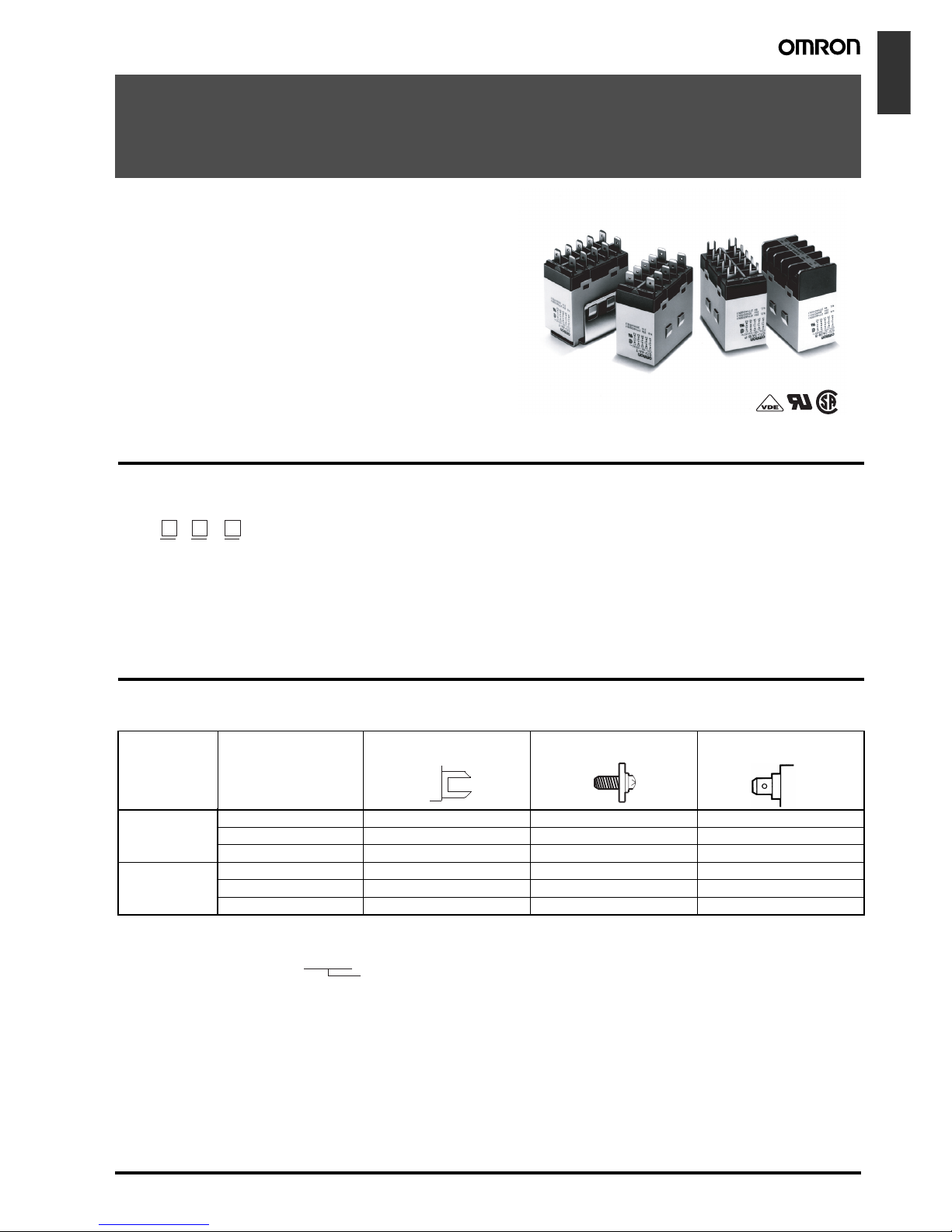
Power Relay G7J A-57
Electromechanical
Relays
Power Relay
G7J
A High-capacity, High-dielectric-strength,
Multi-pole Relay Used Like a Contactor
• Miniature hinge for maximum switching power for motor loads
as well as resistive and inductive loads.
• No contact chattering for momentary voltage drops up to 50%
of rated voltage.
• Withstanding more than 4 kV between contacts that are different in polarity and between the coil and contacts.
• Flame-resistant materials (UL94V-0-qualifying) used for all insulation material.
• Standard models approved by UL and CSA.
Model Number Structure
■ Model Number Legend
Ordering Information
■ List of Models
12 3
G7J - - -
1. Contact Form
4A: 4PST-NO
3A1B: 3PST-NO/SPST-NC
2A2B: DPST-NO/DPST-NC
2. Terminal Shape
P: PCB terminals
B: Screw terminals
T: Quick-connect terminals
(#250 terminal)
3. Contact Structure
Z: Bifurcated contact
None: Single contact
Note: For bifurcated contact type,
output is 1NO (4PST-NO) or
1NC (3PST-NO/SPST-NC).
Mounting type Contact form
PCB mounting 4PST-NO G7J-4A-P, G7J-4A-PZ --- ---
3PST-NO/SPST-NC G7J-3A1B-P, G7J-3A1B-PZ --- --DPST-NO/DPST-NC G7J-2A2B-P --- ---
W-bracket
(see note)
4PST-NO --- G7J-4A-B, G7J-4A-BZ G7J-4A-T, G7J-4A-TZ
3PST-NO/SPST-NC --- G7J-3A1B-B, G7J-3A1B-BZ G7J-3A1B-T, G7J-3A1B-TZ
DPST-NO/DPST-NC --- G7J-2A2B-B G7J-2A2B-T
PCB terminals
Screw terminals
Quick-connect
terminals
Note: These Relays need a W-bracket (sold separately) for mounting.
When ordering specify the voltage.
Example: G7J-4A-P 240 VAC
Rated coil voltage
Page 2
A-58 Power Relay G7J
PCB Terminals
PCB Terminals (Bifurcated Contact)
W-bracket Screw Terminals
Screw Terminals (Bifurcated Contact)
Tab Terminals
Tab Terminals (Bifurcated Contact)
Consult your OMRON representative for details on models not mentioned in this document.
■ Accessories (Order Separately)
Application Examples
• Compressors for air conditioners and heater switching controllers.
• Switching controllers for power tools or motors.
• Lamp controls, motor drivers, and power supply switching control-
lers in copy machines, facsimile machines, and other office equipment.
• Power controllers for packers or food processing equipment.
• Power controllers for inverters.
Contact form Rated voltage (V) Model
4PST-NO 24, 50, 100 to 120,
200 to 240 VAC
G7J-4A-P
12, 24, 48, 100 VDC
3PST-NO/
SPST-NC
24, 50, 100 to 120,
200 to 240 VAC
G7J-3A1B-P
12, 24, 48, 100 VDC
DPST-NO/DPST-NC24, 50, 100 to 120,
200 to 240 VAC
G7J-2A2B-P
12, 24, 48, 100 VDC
Contact form Rated voltage (V) Model
4PST-NO 200 to 240 VAC
24 VDC
G7J-4A-PZ
3PST-NO/
SPST-NC
12, 24 VDC G7J-3A1B-PZ
Contact form Rated voltage (V) Model
4PST-NO 24, 50, 100 to 120,
200 to 240 VAC
G7J-4A-B
12, 24, 48, 100 VDC
3PST-NO/
SPST-NC
24, 50, 100 to 120,
200 to 240 VAC
G7J-3A1B-B
12, 24, 48, 100 VDC
DPST-NO/
DPST-NC
24, 50, 100 to 120,
200 to 240 VAC
G7J-2A2B-B
12, 24, 48, 100 VDC
Contact form Rated voltage (V) Model
3PST-NO/
SPST-NC
200 to 240 VAC G7J-3A1B-BZ
6, 12, 24, 48, 100 VDC
Contact form Rated voltage (V) Model
4PST-NO 24, 50, 100 to 120,
200 to 240 VAC
G7J-4A-T
12, 24, 48, 100 VDC
3PST-NO/
SPST-NC
24, 50, 100 to 120,
200 to 240 VAC
G7J-3A1B-T
12, 24, 48, 100 VDC
DPST-NO/
DPST-NC
24, 50, 100 to 120,
200 to 240 VAC
G7J-2A2B-T
12, 24, 48, 100 VDC
Contact form Rated voltage (V) Model
4PST-NO 200 to 240 VAC G7J-4A-TZ
Name Model Applicable Relay
W-bracket R99-04 for G5F G7J-4A-B
G7J-3A1B-B
G7J-2A2B-B
G7J-4A-T
G7J-3A1B-T
G7J-2A2B-T
Page 3
Power Relay G7J A-59
Electromechanical
Relays
Specifications
■ Coil Ratings
Note: 1. The rated current and coil resistance are measured at a coil temperature of 23°C with tolerances of +15%/–20% for AC rated current and
±15% for DC coil resistance. (The values given for AC rated current apply at 50 Hz or 60 Hz.)
2. Performance characteristic data are measured at a coil temperature of 23°C.
3. The maximum voltage is one that is applicable to the Relay coil at 23°C.
■ Contact Ratings
Note: The values in parentheses indicate values for a bifurcated contact.
■ Characteristics
Rated voltage Rated current Coil resistance Must-operate
voltage
Must-release
voltage
Max. voltage Power
consumption
AC 24 VAC 75 mA --- 75% max. of rated
voltage
15% min. of rated
voltage
110% of rated
voltage
Approx. 1.8 to
2.6 VA
50 VAC 36 mA ---
100 to 120 VAC 18 to 21.6 mA ---
200 to 240 VAC 9 to 10.8 mA ---
DC 6 VDC 333 mA 18 Ω 10% min. of rated
voltage
Approx. 2.0 W
12 VDC 167 mA 72 Ω
24 VDC 83 mA 288 Ω
48 VDC 42 mA 1,150 Ω
100 VDC 20 mA 5,000 Ω
Item Resistive load (cos φ = 1) Inductive load (cosφ = 0.4) Resistive load
Contact mechanism Double break
Contact material Ag alloy
Rated load NO: 25 A at 220 VAC (24 A at 230 VAC)
NC: 8 A at 220 VAC (7.5 A at 230 VAC)
NO: 25 A at 30 VDC
NC: 8 A at 30 VDC
Rated carry current NO: 25 A (1 A)
NC: 8 A (1 A)
Max. switching voltage 250 VAC 125 VDC
Max. switching current NO: 25 A (1 A)
NC: 8 A (1 A)
Contact resistance (see note 2) 50 mΩ max.
Operate time (see note 3) 50 ms max.
Release time (see note 3) 50 ms max.
Max. operating frequency Mechanical: 1,800 operations/hr
Electrical: 1,800 operations/hr
Insulation resistance (see note 4) 1,000 MΩ min. (at 500 VDC)
Dielectric strength 4,000 VAC, 50/60 Hz for 1 min between coil and contacts
4,000 VAC, 50/60 Hz for 1 min between contacts of different polarity
2,000 VAC, 50/60 Hz for 1 min between contacts of same polarity
Impulse withstand voltage 10,000 V between coil and contact (with 1.2 x 50 µs impulse wave)
Vibration resistance Destruction: 10 to 55 to 10 Hz, 0.75-mm single amplitude (1.5-mm double amplitude)
Malfunction: NO:10 to 55 to 10 Hz, 0.75-mm single amplitude (1.5-mm double amplitude)
NC:10 to 26 to 10 Hz, 0.75-mm single amplitude (1.5-mm double amplitude)
Shock resistance
Destruction: 1,000 m/s
2
Malfunction: NO:100 m/s
2
NC:20 m/s
2
Endurance Mechanical: 1,000,000 operations min. (at 1,800 operations/hr)
Electrical: 100,000 operations min. (at 1,800 operations/hr) (see note 5)
Error rate (see note 6) 100 mA at 24 VDC (bifurcated contact: 24 VDC 10 mA)
Ambient temperature Operating: –25°C to 60°C (with no icing or condensation)
Ambient humidity Operating: 5% to 85%
Weight PCB terminal: approx. 140 g
Screw terminal: approx. 165 g
Quick-connect terminal: approx. 140 g
Page 4

A-60 Power Relay G7J
Note: 1. The above values are all initial values.
2. The contact resistance was measured with 1 A at 5 VDC using the voltage drop method.
3. The operate and the release times were measured with the rated voltage imposed with any contact bounce ignored at an ambient tem-
perature of 23°C.
4. The insulation resistance was measured with a 500-VDC megger applied to the same places as those used for checking the dielectric
strength.
5. The electrical endurance was measured at an ambient temperature of 23°C.
6. This value was measured at a switching frequency of 60 operations per minute.
■ Approved Standards
The G7J satisfies the following international standards. Approval for some international markings and symbols are still pending, however, and information on them will be added when they are approved.
UL (File No. E41643)
CSA (File No. LR35535)
Note: *These ratings are bifurcated contact ratings.
Reference
UL approval: UL508 for industrial control devices
UL1950 for information processing equipment including business machines
CSA approval: CSA C22.2 No. 14 for industrial control devices
CSA C22.2 No. 950 for information processing equipment including business machines
VDE (File No. 5381UG)
Note: Add the suffix “-KM” to the model number when ordering.
*These ratings are bifurcated contact ratings.
Reference
VDE approval: EN60255-1-00: 1997
EN60255-23: 1996
Coil ratings Contact ratings Number of test
operations
24 to 265 VAC
6 to 110 VDC
NO contact 25 A 277 VAC, Resistive 30,000
25 A 120 VAC, General Use
25 A 277 VAC, General Use
25 A 240 VAC, General Use 100,000
1.5 kW 120 VAC, Tungsten 6,000
1.5 hp 120 VAC
3 hp 240/265/277 VAC
3-phase 3 hp 240/265/277 VAC 30,000
3-phase 5 hp 240/265/277 VAC
20FLA/120LRA 120 VAC
17FLA/102LRA 277 VAC
TV-10 120 VAC 25,000
25 A 30 VDC, Resistive 30,000
*1 A 277 VAC, General Use 6,000
NC contact 8 A 277 VAC, Resistive 30,000
8 A 120 VAC, General Use
8 A 277 VAC, General Use
8 A 30 VDC, Resistive
*1 A 277 VAC, General Use 6,000
Model Coil ratings Contact ratings
NO contact NC contact
G7J-4A-B(P) (T) (Z)
G7J-2A2B(P) (T)
G7J-3A1B-B(P) (T) (Z)
6, 12, 24, 48, 100 VDC
24, 50, 100 to 120, 200 to 240 VAC
25 A 240 VAC cosφ = 0.4
25 A 240 VAC cosφ = 1
25 A 30 VDC L/R ≥ 1
*1 A 240 VAC cosφ = 0.4
8 A 240 VAC cosφ = 0.4
8 A 240 VAC cosφ = 1
8 A 30 VDC L/R ≥ 1
*1 A 240 VAC cosφ = 0.4
Page 5

Power Relay G7J A-61
Electromechanical
Relays
KEMA (File No. 2001291.02)
Note: Add the suffix “-KM” to the model number when ordering.
*This rating is the bifurcated contact rating.
Reference
KEMA approval: EN60947-4-1 for contacts
IEC947-4-1 for contacts
Engineering Data
Model Coil ratings Contact ratings
NO contact
G7J-4A-B(P) (T) (Z)
G7J-2A2B(P) (T)
200 to 240 VAC Class AC1: 25 A at 220 VAC
11.5 A at 380 to 480 VAC
Class AC3: 11.5 A at 220 VAC and 8.5 A at 380
to 480 VAC
*Class AC1: 1 A at 220 VAC
G7J-3A1B-B(P) (T) (Z) 6, 12, 24, 48, 100 VDC
24, 50, 100 to 120, 200 to 240 VAC
50
70
300
5,000
3,000
1,000
700
500
100
300
Maximum Switching Power
Switching voltage (V) Switching current (A)
220 VAC (NC contact)
220 VAC (NO contact)
Endurance
Switching current (A)
Endurance (x10
3
operations)
AC resistive load
(cosφ = 1)
AC inductive load
(cosφ = 0.4)
(NC contact)
DC resistive
load (NO
contact)
DC resistive load
(NC contact)
AC resistive load
(cosφ = 1)
AC inductive load
(cosφ = 0.4)
(NO contact)
Malfunctioning Shock
G7J-2A2B
Terminals upwards
Button downwards
A1 downwards
Button upwards
Shock direction
Not energized
Energized
A2 downwards
Terminals
downwards
Unit: m/s
2
Number of samples: 5
Measurement conditions: Increase and decrease
the specified shock gradually imposed in ±X, ±Y,
and ±Z directions three times each with the Relay
energized and not energized to check the shock
values that cause the Relay to malfunction.
Criteria: There must not be any contact
separation for 1 ms or greater with a shock of
100 m/s
2
imposed when the coil is energized or
with a shock of 20 m/s
2
when the coil is not
energized.
Page 6

A-62 Power Relay G7J
Motor Load
Ambient Temperature vs.
Must-operate and Mustrelease Voltage
Ambient Temperature vs.
Coil Temperature Rise
Number of Relays: 5
Number of Relays: 5
Must-operate voltage
Must-release voltage
Must-operate voltage
Must-release voltage
Number of Relays: 5
Number of Relays: 5
Ambient temperature (°C)
Ambient temperature (°C)
Ambient temperature (°C)
Ambient temperature (°C)
Must-operate and reset voltage (%)
Must-operate and reset voltage (%)
Coil temperature rise (°C)Coil temperature rise (°C)
G7J 100 to 120 VAC
G7J 24 VDC
G7J-4A 100 to 120 VAC
G7J-4A 24 VDC
Item G7J-4A-P, G7J-3A1B-P, G7J-4A-B, G7J-3A1B-B, G7J-4A-T, G7J-3A1B-T
Load 3φ, 220 VAC, 2.7 kW (with a inrush current of 78 A and a breaking current of 13 A)
Endurance Electrical: 100,000 operations min.
Page 7

Power Relay G7J A-63
Electromechanical
Relays
Dimensions
Note: All units are in millimeters unless otherwise indicated.
35±0.1
7.6
55.2
4.3
2
43.2
Screw Terminals with W-bracket
Mounting Holes
G7J-4A-B, G7J-4A-BZ, G7J-3A1B-B, G7J-3A1B-BZ, G7J-2A2B-B
Ten, M3.5
34.5 max.
51.5 max.
64 max.
Two, 4.5 dia. or M4
Quick-connect Terminals with W-bracket
G7J-4A-T, G7J-4A-TZ, G7J-3A1B-T, G7J-3A1B-TZ, G7J-2A2B-T
34.5 max.
51.5 max.
64 max.
Two, 4.5 dia. or M4
Note: W-bracket is sold
separately.
Mounting Holes
PCB Terminals with PCB Mounting
Mounting Dimensions
G7J-4A-P, G7J-4A-PZ, G7J-3A1B-P, G7J-3A1B-PZ, G7J-2A2B-P
33.5
max.
51.5 max.
51 max.
20, 1.8
+0.1
dia.
0
Page 8

A-64 Power Relay G7J
35±0.1
24
44 4.4
30
7
9
29
35
14
24
34
44
A2 A1 A2 A1 A2 A1
43
42 41 42 41
33 34 33
32 31
23 24 23 24 23
13 14 13 14 13
28
Terminal Arrangement/Internal Connections
Accessories (Order Separately)
R99-04 W-bracket (for G5F)
G7J-4A-P(B) (T) (Z) G7J-3A1B-P(B) (T) (Z) G7J-2A2B-P(B) (T)
The coil has no polarity.
Two, 4.5 dia.
Note: Terminals 43 and 44 of the
G7J-4A-P(B)(T)(Z) and
contacts 41 and 42 of the
G7J-3A1B-P(B)(T)(Z) are
bifurcated contacts.
Mounting Holes
Two, 4.5 dia. or M4
Page 9

Power Relay G7J A-65
Electromechanical
Relays
Precautions
■ Correct Use
Installation
PCB Terminal-equipped Relays weigh approximately 140 g. Be sure
that the PCB is strong enough to support them. We recommend
dual-side through-hole PCBs to reduce solder cracking from heat
stress.
Mount the G7J with its test button facing downwards. The Relay may
malfunction due to shock if the test button faces upwards. Be careful
not to press the test button by mistake because the contacts will go
ON if the test button is pressed.
Be sure to use the test button for test purposes only.
The test button is used for Relay circuit tests, such as a circuit continuity test. Do not attempt to switch the load with the test button.
Micro Loads
The G7J is used for switching power loads, such as motor, transformer, solenoid, lamp, and heater loads. Do not use the G7J for
switching minute loads, such as signals. Use a Relay with a bifurcated contact construction for switching micro loads, in which case,
however, only SPST-NO or SPST-NC output is obtained.
Soldering PCB Terminals
Be sure to solder the PCB terminals manually only. In the case of
automatic soldering, some flux may stick to the test button and the
G7J. As a result, the G7J may malfunction.
The G7J is not of enclosed construction. Therefore, do not wash the
G7J with water or any detergent.
Connecting
Refer to the following diagram when connecting a wire with a screw
terminal to the G7J.
Allow suitable slack on leads when wiring, and do not subject the terminals to excessive force.
Tightening torque: 0.98 N·m
Do not impose excessive external force on the G7J in the horizontal
or vertical directions when inserting the G7J to the Faston receptacle
or pulling the G7J out from the Faston receptacle. Do not attempt to
insert or pull out more than one G7J Unit together.
Do not solder the tab terminals.
Note: Numbers in parentheses are for air feed use.
Operating Coil
Internal Connections of Coils
If a transistor drives the G7J, check the leakage current, and connect
a bleeder resistor if necessary.
The AC coil is provided with a built-in full-wave rectifier. If a triac,
such as an SSR, drives the G7J, the G7J may not release. Be sure to
perform a trial operation with the G7J and the triac before applying
them to actual use.
Terminal Receptacle Housing
#250 terminal
(6.35 mm in
width)
AMP170333-1
(170327-1)
AMP170334-1
(170328-1)
AMP170335-1
(170329-1)
AMP172076-1: natural
AMP172076-4: yellow
AMP172076-5: green
AMP172076-6: blue
7.6
7
4.5
8.8
M3.5
A2 A1
A1A2
DC coil
AC coil
Page 10

A-66 Power Relay G7J
In the interest of product improvement, specifications are subject to change without notice.
ALL DIMENSIONS SHOWN ARE IN MILLIMETERS.
To convert millimeters into inches, multiply by 0.03937. To convert grams into ounces, multiply by 0.03527.
Cat. No. J088-E1-03
 Loading...