

Omron G70A-ZOC16-3, G70A-ZOC16-4, G70A-ZIM16-5 Datasheet
I/O Block Base G70A 1
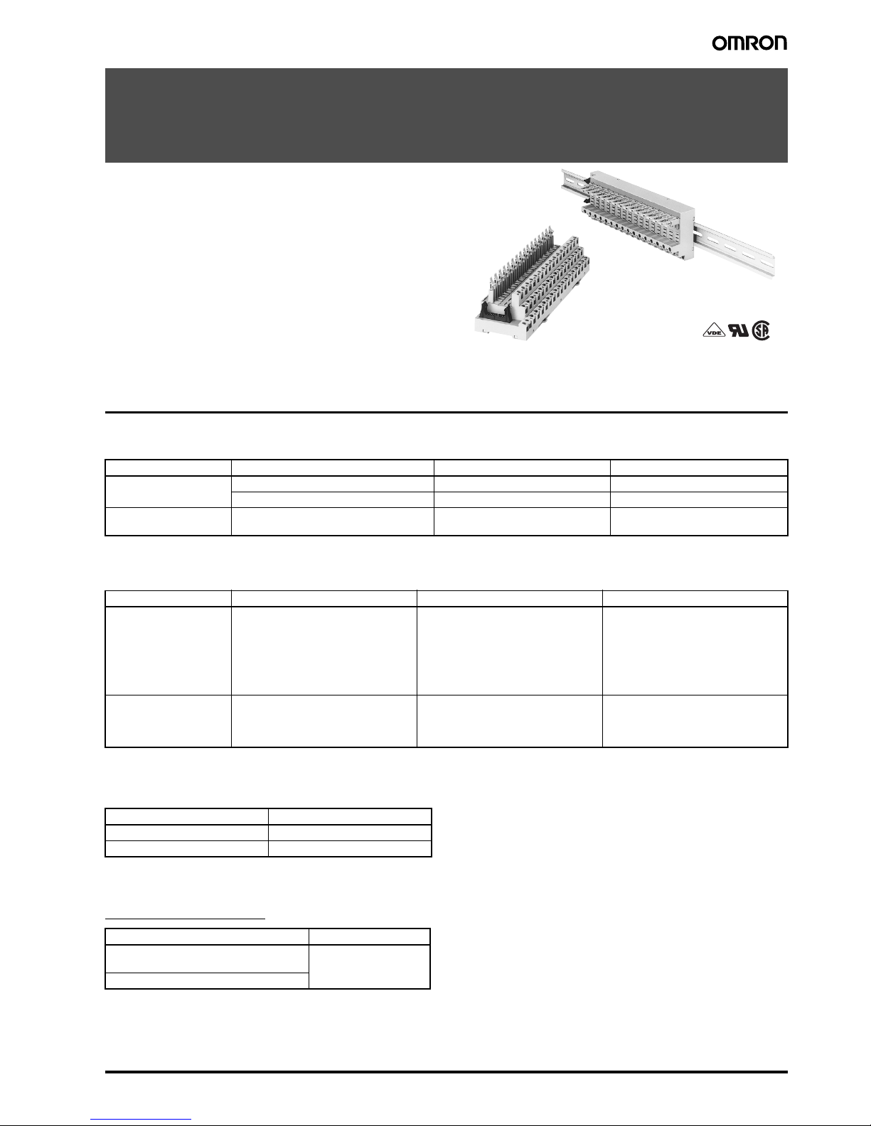
I/O Block Base
G70A
Reduces Wiring while Providing I/O
Flexibility
• Mount I/O relays and I/O SSRs freely.
• Electric-shock preventive (finger-touch protection) terminal
block incorporated conforming to VDE 0160.
• Connects to the PC and SBC easily via a connector.
• DIN track mounted.
• I/O Block conforming to VDE 0160.
Ordering Information
■ List of Models
Note: Each relay to be mounted must incorporate a coil that has proper specifications within the maximum rated voltage range.
■ Suitable Relay/SSR
Note: G2R-13-SN has twin cross-bar contacts.
■ Connecting Sockets for I/O Terminal Expansion
■ Accessories (Order Separately)
G78-16-E Short Bar
Classification Internal I/O circuit common Rated voltage Model
Output NPN (+ common) 24 VDC G70A-ZOC16-3
PNP (– common) 24 VDC G70A-ZOC16-4
Input NPN/PNP 110 VDC max., 240 VAC max.
(See note)
G70A-ZIM16-5
Classification I/O Block Base PCB Relay Solid State Relay
Output NPN:G70A-ZOC16-3
PNP:G70A-ZOC16-4
G2R-1-S
G2R-1-SN
G3R-OA202SZN
G3R-OA202SLN
G3R-ODX02SN
G3R-OD201SN
G3RZ-201SLN
H3RN-1
H3RN-11
Input G70A-ZIM16-5 G2R-1A3-SN
G2R-13-SN
G2R-1A3-SND
G2R-13-SND
G3R-IAZR1SN
G3R-IDZR1SN
G3R-IDZR1SN-1
Model Number of poles
P2RF-05-E 1 pole (G2R: 1 pole usage)
P2RF-08-E 2 poles (G2R: 2 poles usage)
Applicable model Model
G70A-ZOC16-3
G70A-ZOC16-4
G78-16-E
G70A-ZIM16-5
2 I/O Block Base G70A
Specifications
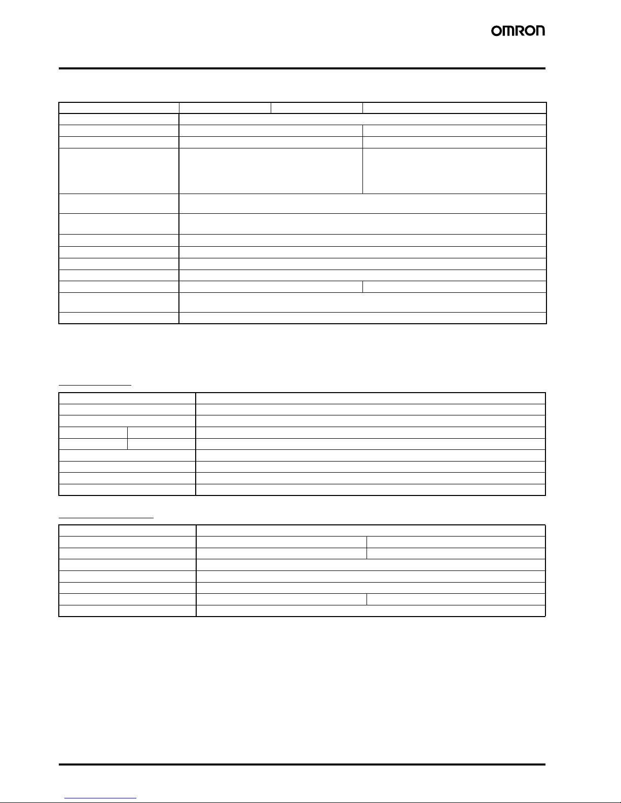
■ Ratings/Characteristics
Note: Use a DC relay with a built-in diode because a DC relay without a built-in diode does not absorb any coil surge.
■ Relay (G2R-1-S, G2R-1-SN)
Coil Ratings
Contact Ratings
Item G70A-ZOC16-3 G70A-ZOC16-4 G70A-ZIM16-5
Contact resistance 10 mΩ (excluding the resistance of the relay to be used)
Permissible current 10 A 100 mA
Max. operating voltage 380 VAC, 125 VDC 30 VDC
Dielectric strength 4,000 VAC, 50/60 Hz for 1 min between connector and
output terminals
2,000 VAC, 50/60 Hz for 1 min between output terminals
250 VAC, 50/60 Hz for 1 min between connectors
4,000 VAC, 50/60 Hz for 1 min between connector and
input terminals
2,000 VAC, 50/60 Hz for 1 min between coil terminals
250 VAC, 50/60 Hz for 1 min between connectors
Insulation resistance Between connector and I/O terminals: 1,000 MΩ (at 500 V)
Other: 100 MΩ (at 500 V)
Vibration resistance Malfunction: 10 to 61.2 to 10 Hz, 0.1-mm single amplitude (0.2-mm double amplitude); 61.2 to 150 to 61.2 Hz,
14.7 m/s
2
Shock resistance
Malfunction: 200 m/s
2
Noise immunity Noise level: 2.0 kV; pulse width: 100 ns to 1 µs
Ambient temperature Operating: 0°C to 55°C (with no icing)
Ambient humidity Operating: 35% to 85%
Coil surge absorption element Diode: 1 A, 400 V Varistor (see note)
Protection diode for inverse
connection
Diode (2 A, withstand inverse voltage: 40 V)
Tightening torque 0.59 N·m
Rated voltage 24 VDC
Rated current 21.8 mA
Coil resistance 1,100 Ω
Coil inductance Armature OFF 4.27
(H) (ref. value) Armature ON 8.55
Must operate voltage 70% min. of rated voltage
Must release voltage 15% min. of rated voltage
Max. voltage 110% of rated voltage
Power consumption Approx. 0.53 W
Number of poles 1 pole
Load Resistive load (cosφ = 1) Inductive load (cosφ = 0.4; L/R = 7 ms)
Rated load 10 A at 250 VAC; 10 A at 30 VDC 7.5 A at 250 VAC; 5 A at 30 VDC
Rated carry current 10 A
Max. operating voltage 380 VAC, 125 VDC
Max. operating current 10 A
Max. switching capacity 2,500 VA, 300 W 1,875 VA, 150 W
Min. permissible load 100 mA at 5 VDC
I/O Block Base G70A 3
■ Relay (G2R-1A3-SN (SND), G2R-13-SN (SND))
Coil Ratings
Note: 1. The rated current and coil resistance are measured at a coil temperature of 23°C with a tolerance of
+15%
/
–20%
(AC rated current) or ±10%
(DC coil resistance).
2. LEDs are used for the built-in operation indicator. For models equipped with these indications, the VAC rated current must be increased
by approximately 1 mA; the VDC rated current, by approximately 4 mA.
3. Operating characteristics are measured at a coil temperature of 23°C.
Contact Ratings
Refer to Ratings/Characteristics of G70A-ZIM16-5.
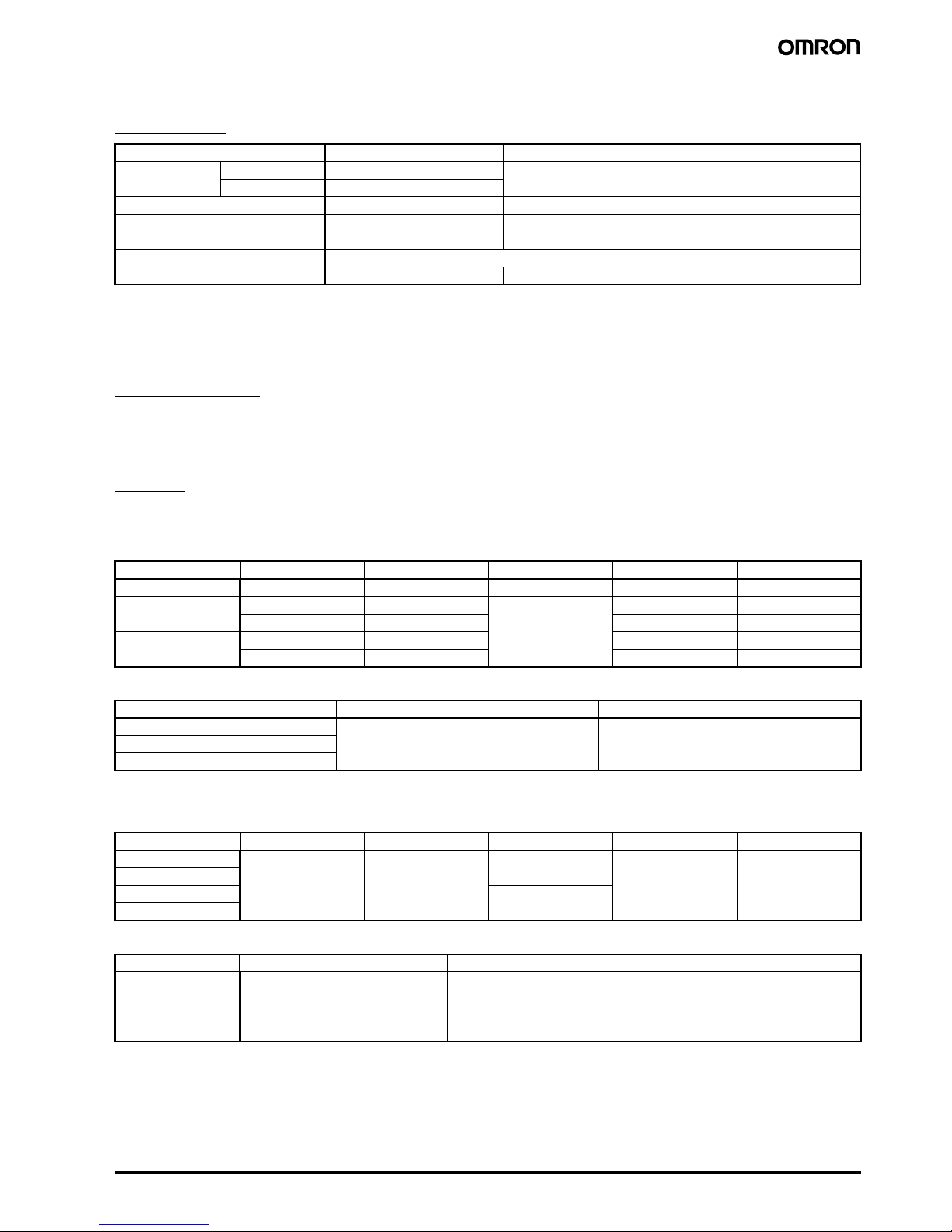
■ SSR
Ratings
Input Module
Input
Output
Output Module
Input
Output
Note: The minimum current value is measured at 10°C min.
Rated voltage 230 VAC 12 VDC 24 VDC
Rated current 50 Hz 3.7 mA 43.6 mA 21.8 mA
60 Hz 3.1 mA
Coil resistance 30,000 Ω 275 Ω 1,100 Ω
Must operate voltage 80% max. of rated voltage 70% max. of rated voltage
Must release voltage 30% min. of rated voltage 15% min. of rated voltage
Max. voltage 110% of rated voltage
Power consumption Approx. 0.7 W (60 Hz) Approx. 0.53 W
Model Rated voltage Operating voltage Input current Must operate voltage Must release voltage
G3R-IAZR1SN 100 to 240 VAC 60 to 264 VAC 15 mA max. 60 VAC max. 20 VAC min.
G3R-IDZR1SN 5 VDC 4 to 6 VDC 8 mA max. 4 VDC max. 1 VDC min.
12 to 24 VDC 6.6 to 32 VDC 6.6 VDC max. 3.6 VDC min.
G3R-IDZR1SN-1 5 VDC 4 to 6 VDC 4 VDC max. 1 VDC min.
12 to 24 VDC 6.6 to 32 VDC 6.6 VDC max. 3.6 VDC min.
Model Logic level supply voltage Logic level supply current
G3R-IAZR1SN 4 to 32 VDC 0.1 to 100 mA
G3R-IDZR1SN
G3R-IDZR1SN-1
Model Rated voltage Operating voltage Input current Must operate voltage Must release voltage
G3R-OA202SZN 5 to 24 VDC 4 to 32 VDC 15 mA max.
(at 25°C)
4 VDC max. 1 VDC min.
G3R-OA202SLN
G3R-ODX02SN 8 mA max.
G3R-OD201SN
Model Load voltage Load current (see note) Inrush current
G3R-OA202SZN 75 to 264 VAC 0.05 to 2 A 30 A (60 Hz, 1 cycle)
G3R-OA202SLN
G3R-ODX02SN 4 to 60 VDC 0.01 to 2 A 8 A (10 ms)
G3R-OD201SN 40 to 200 VDC 0.01 to 1.5 A 8 A (10 ms)
 Loading...