

Page 1

3G3RV-P10ST@-E
G7/F7/L7/E7 inverter PLC
The OMRON PLC technology embedded in
the OMRON Yaskawa inverter family
• OMRON PLC programmability in the
OMRON Yaskawa inverters.
• Flexibility and intelligence in the OMRON Yaskawa
inverter family.
• Wireless installation and seamless access to the
inverter parameters and analogue/digital inputs and
outputs.
• OMRON Compobus/S fieldbus inside. Thus, able to
control up to 256I/O's.
• Easy to integrate in the automation world:
DeviceNet type available.
• Standard OMRON tools can be used for programming and commissioning.
• Ideal for applications like:
• Pump sequencing, remote control, water
treatment,etc together with the HVAC inverter:
E7&E7 IP54.
• Lift as control sequence inside, using the lift
inverter: L7.
• Cranes, winding/rewinding, position control, oth-
ers combined with the powerful flux vector control
inverter: F7Z.
• General purpouse using the high technology of
G7 3-Level vector control.
System configuration
DeviceNet
RS-232C
RS-422
CX-One (CX-Drive)
(CX-Programmer)
HMI interface
Other serial devices
Varispeed + PLC
CompoBus/S communication path
Terminator
16 of 32 slaves max.
365G7/F7/L7/E7 inverter PLC
Page 2

Type designation
PLC inverter
3G3RV-P10ST8-DRT-E
Inverter series
Number of I/O's
Options
Output RTC RS422 Remarks
- NPN NO NO
1NPN NO YES
2 NPN YES NO
3 NPN YES YES
5 PNP NO NO
6 PNP NO YES
7PNP YES NO
8 PNP YES YES Standard
DeviceNet slave
-No
DRT Yes
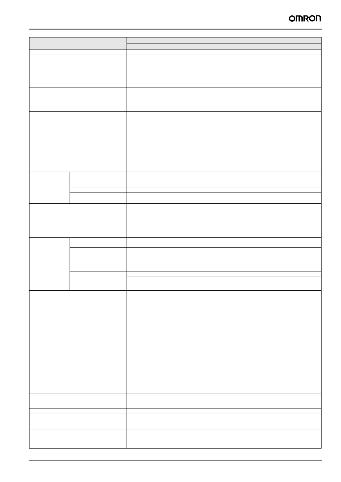
Specifications
Specifications by product
Item 3G3RV-P10ST8-E 3G3RV-P10ST8-DRT-E
PLC core CPM2C-S CPM2C-S
Inputs 6 24 VDC inputs 6 24 VDC inputs
Outputs 4 sourcing/PNP transistor outputs 4 sourcing/PNP transistor outputs
Peripheral port Yes Yes
RS-232C port Yes Yes
RS-422 port No Yes
Calendar/clock Yes Yes
Memory backup Flash memory and battery Flash memory and battery
Compobus/S master interface Yes Yes
Encoder interface Yes Yes
DeviceNet Slave interface No Yes
General specifications
Item Specifications
3G3RV-P10ST8-E 3G3RV-P10ST8-DRT-E
Rated power supply voltage 24 VDC
Communications power supply voltage --- 11 to 25 VDC (supplied by communications connector)
Power consumption
supply
Vibration resistance 10 to 20 Hz, 9.8 m/s2 max.
Ambient operating temperature -10 to 45 °C
Ambient operating relative humidity 10% to 90% (no condensation)
Ambient storage temperature -20 to 70 °C
Atmosphere Must be free from corrosive gas
Control method Store program method
I/O control method Cyclic scan method
Programming language Ladder chart method
Instruction length 1 step/1 instruction; 1 to 5 words/1 instruction
Instruction types Basic 14 types (same as for programmable slaves)
Processing speed Basic instructions 0.64 µs (LD)
Program capacity 4,096 words
Maximum number of I/O points 10
Input bits 00000 to 00015 (6 physical inputs)
Output bits 01000 to 01003 (4 physical outputs)
CompoBus/S input bits 128 bits: IR 02000 to IR 02715 (bits not used for CompoBus/S input bits can be used for work bits.)
CompoBus/S output bits 128 bits: IR 03000 to IR 03715 (bits not used for CompoBus/S output bits can be used for work bits.)
Inverter interface Direct interface with inverter through
Inverter interface bits 176 bits: IR 20000 to IR 21015
Encoder interface bits 48 bits: IR 02900 to IR 02915 and IR 04800 to IR 04915
Work bits 448 bits: IR 02800 to IR 02815, IR 03800 to IR 04715, and IR 21100 to IR 22715
Special bits (SR area) 448 bits: SR 22800 to SR 25507 (words SR 228 to SR 255)
Temporary bits (TR area) 8 bits (TR 0 to TR 7)
Holding bits (HR area) 320 bits: HR 0000 to HR 1915 (words HR 00 to 19)
Auxiliary bits (AR area) 384 bits: AR 0000 AR 2315 (words AR 00 to AR 23)
Internal power 2 W (supplied internally) (see note) 3 W (supplied internally) (see note)
Communications power supply --- 30 mA max.
Special 105 types, 185 instructions (same as for programmable slaves)
Special instructions 7.8 µs (MOV)
+10%
/
(external power supply for I/O)
-15%
20 to 50 Hz, 2 m/s2 max
• IR-memory
• DM-memory
• Transfer command
366 3G3RV-P10ST@-E
Page 3
Item Specifications
Link bits (LR area) 256 bits: LR 0000 to LR 1515 (words LR 00 to LR 15)
Timers/counters 256 timers/counters (TIM/CNT 000 to TIM/CNT)
CompoBus/S master functions Remote I/O devices can be allocated up to 256 I/O points (128 inputs and 128 outputs) in input area IR 020 to
DeviceNet slave functions Up to 64 words (32 input words and 32 output words) can be allocated to the DeviceNet master's I/O.
DM area Read/write 2,029 words (DM 0000 to DM 0999, DM 1019 to DM 2047)
Read only 456 words (DM6144 to 6599)
Inverter interface 19 words (DM 2022 to DM 2040)
Encoder interface 14 words (DM 1986 to DM 1999)
Interrupts Interrupt inputs
High-speed counters High-speed counter 1 input,
Encoder interface 3 input modes:
Pulse outputs • 2 outputs:
Synchronized pulse control 1 point, see notes 5 and 6
Pulse catch inputs 2 bits
Analog volume None
Input time constant
(ON response time = OFF response time)
Clock/Calendar function Shows the current year, month, day of the week, day of the month, hour, minute, and second.
Communication function Port 1 = Peripheral and RS-422:
PLC setup 56 words (DM 6599 to DM 6655)
see note 5
Differential phase mode (5 kHz)
Pulse plus direction input mode
(20 kHz)
Up/down input mode (20 kHz)
Increment mode (20 kHz)
Interrupt inputs (counter mode)
2 inputs
Incrementing counter (2 kHz)
Decrementing counter (2 kHz)
3G3RV-P10ST8-E 3G3RV-P10ST8-DRT-E
1-ms timers: TMHH(--)
10-ms timers: TIMH(15)
100-ms timers: TIM
1-s/10-s timers: TIML(--)
Decrementing counters: CNT
Reversible counters: CNTR(12)
IR 027 and output area IR 030 to IR 037.
• The node numbers can be set to 0 to 7 (128-point mode) or 0 to 15 (256-point mode).
• The communications mode can be set to high-speed mode (max. length 100 m) or long-distance mode
(max. length 500 m).
The master's I/O can be allocated to the following data areas:
• Explicit message communications are supported. Any 3G3RV-P10ST data area can be accessed from the
• The communications speed can be set to 500 kbps (total network length 100 m max.), 250 kbps (total network
DM 2000 to DM 2021: error log storage area
2 inputs
Response time: 50 µs
Interval timer interrupts
1 input
Set value: 0.5 to 319,968 ms
Precision: 0.1 ms
No interrupt
Count-check interrupt
(An interrupt can be generated when the count equals the set value or the count lies within a preset range.)
No interrupt
Count-up interrupt
Maximum input frequency 50 kHz
Maximum counter range 4,294,967,295 (232-1)
Two capture registers, 3 selectable registration inputs
One comparison value
Counter reset through software or Z-phase
Interrupt function
• 2 outputs:
• 1 output:
Minimum pulse input: 50 µs max.
Used in common by input interrupts and input interrupt counter mode.
Determines the input time constant for all inputs. (settings: 1, 2, 3, 5, 10, 20, 40, or 80 ms)
Port 2 = RS-232C port:
IR 000 to IR 049
IR 200 to IR 227
DM 0000 to DM 2047
LR 00 to LR 15
HR 00 to HR 19
AR 00 to AR 23 (3G3RV-P10ST ' master; read-only)
TC 000 to TC 255
DeviceNet master.
length 250 m max.), or 125 kbps (total network length 500 m max.).
Scheduled interrupts
One-shot interrupt
Differential-phase (up/down)
Pulse plus direction
Up/down pulse
Single-phase pulse output without acceleration/deceleration (see note 6.)
10 Hz to 10 kHz
Variable duty ratio pulse output (see note 6.)
0.1 to 999.9 Hz, duty ratio 0 to 100%
Pulse output with trapezoidal acceleration/deceleration (see note 6.)
Pulse plus direction output, up/down pulse output, 10 Hz to 10 kHz
Input frequency range: 10 to 500 Hz, 20 Hz to 1 kHz, or 300 Hz to 20 kHz
Output frequency range: 10 Hz to 10 kHz
Host link, peripheral bus, no-protocol, programming console
Host link, no-protocol, 1:1 PLC link, 1:1 NT link
G7/F7/L7/E7 inverter PLC 367
Page 4
Item Specifications
3G3RV-P10ST8-E 3G3RV-P10ST8-DRT-E
Power-interruption hold function Holds the contents of HR, AR, CNT, and DM areas.
Memory backup (see notes 1 and 2.) Flash memory: Program, read-only DM area, and PC setup
Memory backup: The read/write DM area, HR area, AR area, and counter values are backed up.
(The battery has a 5-year lifetime at 25 °C and it is replaceable.)
Self-diagnostic function CPU errors, memory errors, communications errors, setting errors, battery errors
Program check No END instruction, program errors (regularly checked during operation)
Connected tools CX-programmer After version 2.1
Programming console C200H-PRO27, CQM1-PRO01
SSS PC98 & PC/AT (SYSMAC support software, all versions)
CX-drive Version 1 or higher
Note: 1. The DM area, HR area, AR area, and counter values are
backed up. If the backup battery or capacitor is discharged,
the contents of these areas will be lost and the data values will
revert to the defaults.
2. The contents of the program area, read-only DM area
(DM6144 to DM6599), and PLC setup (DM 6600 to DM 6655)
are stored in flash memory. The contents of these areas will
be read from flash memory the next time the power is turned
ON, even if the backup battery or capacitor is discharged.
3. Changes made while in MONITOR mode using, for example,
online editing, are written to flash memory in real-time.
4. The above figure for power consumption includes the power
consumption of the programming console.
5. This input is shared by the high-speed counter and synchro-
nized pulse control functions.
6. This output is shared by the pulse output and synchronized
pulse control functions.
When data has been changed in any of these areas, write the
new values to flash memory by switching the 3G3RV-P10ST
to MONITOR or RUN mode, or by turning the power OFF and
then ON again.
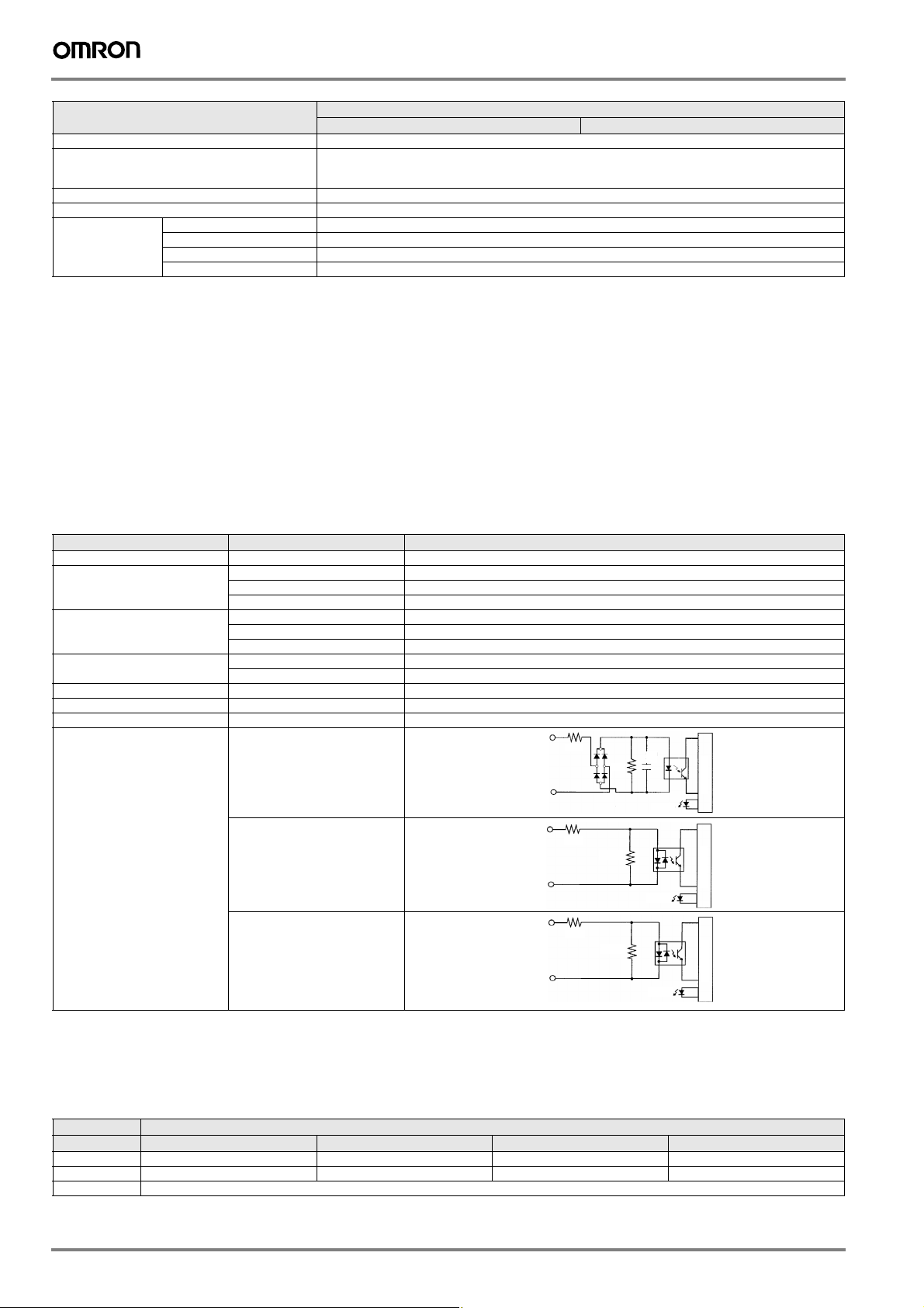
I/O specifications
Input specifications
Item Inputs Specification
Input voltage All 24 VDC
Input impedance IN 00000 to IN 00001 2.7 kΩ
IN 00002 to IN 00004 3.9 kΩ
IN 00005 4.7 kΩ
Input current IN 00000 to IN 00001 8 mA typical
IN 00002 to IN 00004 6 mA typical
IN 00005 5 mA typical
ON voltage/current IN 00000 to IN 00001 17 VDC min., 5 mA
IN 00002 to IN 00005 14.4 VDC min., 3.5 mA
OFF voltage/current All 5.0 VDC max., 1.1 mA
ON delay All 1 to 80 ms max. Default: 10 ms (see note.)
OFF delay All 1 to 80 ms max. Default: 10 ms (see note.)
Circuit configuration IN 00000 to IN 00001
IN 00002 to IN 00004
IN 00005
+10%
/
-15%
IN
2.7 kΩ
COM
COM
COM
IN
3.9 kΩ
IN
4.7 kΩ
820 Ω
750 Ω
0.01
µF
1kΩ
Input LED
Input LED
Input LED
Internal circuits
Internal circuits
Internal circuits
Note: The input time constant can be set to 1, 2, 3, 5, 10, 20, 40, or 80 ms in the PLC setup.
High-speed counter inputs
The following unit input bits can be used as high-speed counter inputs. The maximum count frequency is 5 kHz in differential phase mode and
20 kHz in the other modes.
Input Function
IN 00000 A-phase pulse input Pulse input Increment pulse input Increment pulse input
IN 00001 B-phase pulse input Direction input Decrement pulse input Normal input
IN 00002 Z-phase pulse input or hardware reset input (IN00002 can be used as a normal input when it is not used as a high-speed counter input.)
Differential phase mode Pulse plus direction input mode Up/down input mode Increment mode
368 3G3RV-P10ST@-E
Page 5

The minimum pulse widths for inputs IN00000 (A-phase input) and IN00001 (B-phase input) are as follows:
Pulse plus direction input mode,
Differential phase mode
up/down inputmode, Increment mode
100 µs min.
T
1T2T3T4
T
: 12.5 µs min.
1 T2 T3 T4
90%
50%
10%
90%
50%
10%
ON
OFF
50 µs min.
12.5 µs
min.
12.5 µs
min.
90%
50%
10%
Phase A
Phase B
ON
OFF
ON
OFF
The minimum pulse width for input IN00002 (Z-phase input) is as follows:
50 µs min.
Phase Z
ON
OFF
500 µs min.
90%
50%
10%
Interrupt inputs
3G3RV-P10ST is equipped with inputs that can be used as interrupt inputs (interrupt input mode or counter mode) and quick-response inputs.
The minimum pulse width for these inputs is 50 µs.
Inputs IN 00003 and IN 00004 can be used as interrupt inputs.
Output specifications
Transistor outputs (sourcing/PNP)
Item Specification
Maximum switching capacity 4.5 to 30 VDC, 0.2 A/output
Minimum switching capacity 0.5 mA
Maximum inrush current 0.9 A for 10 ms
Leakage current 0.1 mA
Residual voltage 1.5 V max.
ON response time 20 µs max.
OFF response time 40 µs max. for 4.5 to 26.4 VDC, 10 to 100 mA
Fuse One fuse per output (cannot be replaced by user)
Circuit configuration
0.1 ms max for 4.5 to 30 VDC, 10 to 200 mA
Internal
circuits
Output LED
COM (+)
OUT
24 VDC
Note: When using OUT 01000 or OUT 01001 as a pulse output, con-
nect a dummy resistor as required to bring the load current
between 0.01 and 0.1 A. If the load current is below 0.1 A, the
ON-to-OFF response time will be longer and high-speed pulses
(source-type transistor outputs) will not be output. If the load current is above 0.1 A, the transistor will generate more heat and
components may be damaged.
Encoder input specifications
Signal level All
Input impedance A- and B-phase
Z-phase
Response frequency A- and B-phase
Z-phase
Circuit configuration A- and B-phase
Z-phase
EIA RS-422-A standards
280 Ω
260 Ω
50 kHz max.
1 kHz max.
OUT
!Caution
Do not apply voltage in excess of the maximum switching capacity
to an output terminal. It may result in damage to the product or fire.
330 Ω
A
B
410 Ω
220 pF
/A
/B
/Z
330 Ω
180 Ω
Z
560 Ω
680 pF
180 Ω
Intrnal circuits
Intrnal circuits
G7/F7/L7/E7 inverter PLC 369
Page 6

Operation
CPU unit component descriptions
1. DI P switch
16. D eviceNet
node address
14. Battery15. Low battery detection switch
17. D eviceNet ind icators
18. CompoBus/S indicators
5. PLC status indicators
4. High-speed counter indicators
3. Output indicators
2. Input indicators
13. FE connection
10. Terminating resistance switch
7. Co mmunicatio ns switch
6. Communications port
9. RS-422/485 port
11. CompoBus/S port
1. DIP switch
RS-232C and peripheral port settings
•
Pin 1 Effective port settings
The ports operate according to the settings in the
OFF
(default)
PLC setup.
ON
1
3
4
2
RS-232C port settings: DM 6645 to DM 6649
Peripheral port settings: DM 6650 to DM 6654
ON The ports operate with the standard communications
settings.
• Operating mode at startup
Pin 2 determines the operating mode at startup only if there isn't a
programming device connected to the peripheral port.
Programming device
connected
None RUN mode PROGRAM mode
Programming console Operating mode set on the programming console's
Other device PROGRAM mode
Startup mode with
Pin 2 OFF (default)
mode switch
Startup mode with
Pin 2 ON
2. Input indicators (yellow)
IN0
IN1
IN2
IN3
IN4
IN5
OUT0
The input indicators are lit when the corresponding
OUT1
input terminal is ON. The status of an input indicator
OUT2
will reflect the status of the input even when that input
OUT3
is being used for a high-speed counter.
Note: 1. When interrupt inputs are used in interrupt input mode, the in-
dicator may not light even when the interrupt condition is met
if the input is not ON long enough.
2. Input indicators will reflect the status of the corresponding in-
puts even when the PLC is stopped, but the corresponding input bits will not be refreshed.
8. DeviceNet port
12. Digital I/O and
encoder interface
3. Output indicators (yellow)
The output indicators are lit when the corresponding output terminal is
ON. The indicators are lit during I/O refreshing. The status of an output
indicator will also reflect the status of the corresponding output when
the output is being used as a pulse output.
4. High-speed counter indicators (yellow)
A
B
Z
The indicators are lit when the corresponding input
terminal is ON.
5. PLC status indicators
The following indicators show the operating status of the PLC.
PWR
RUN
ERR/ALM
COMM1
COMM2
Indicator Status Meaning
PWR
(green)
RUN
(green)
ERR/ALM
(red)
ON Power is being supplied to the unit
OFF Power isn't being supplied to the unit
ON The PLC is operating in RUN or
MONITOR mode
OFF The PLC is in PROGRAM mode or
ON A fatal error has occurred.
a fatal error has occurred.
(PLC operation stops.)
Flashing A non-fatal error has occurred.
(PLC operation continues.)
OFF Indicates normal operation.
COMM1
(yellow)
COMM2
(yellow)
Flashing Data is being transferred via the
peripheral or RS-422/485 port.
OFF Data isn't being transferred via
Flashing Data is being transferred via the
communications port.
RS-232C port
OFF Data isn't being transferred via
communications port.
370 3G3RV-P10ST@-E
Page 7

6. Communications port
Connects the PLC to a programming device (including programming
consoles), host computer, or standard external device. Use a proper
connecting cable (CPM2C-CN111, CS1W-CN114, CS1W-CN118, or
CS1W-CN226).
Note: 1. A CQM1H-PRO01-E programming console can be connect-
ed directly to the PLC.
2. A C200H-PRO27-E programming console can be connected
directly to the PLC with a CS1W-CN224/CN624 connecting
cable.
3. Use a CPM2C-CN111 or CS1W-CN114 connecting cable to
connect to the communications port as a peripheral port. The
communications port can be used simultaneously as both a
peripheral port and RS-232C port by using the CPM2CCN111 connecting cable.
4. Use a CPM2C-CN111, CS1W-CN118 or CS1W-CN226 con-
necting cable to connect to the communications port as a RS232C port. The communications port can be used simultaneously as both a peripheral port and RS-232C port by using
the CPM2C-CN111 connecting cable
Note: The peripheral port and RS-422/485 port cannot be used simul-
taneously. When using the peripheral port disconnect any
devices connected to the RS-422/485 port.
7. Communications switch
Switch to select port 1 type of connected device
Position Communication port 1
OFF (up) (default) Programming console
ON (down) RS-422/485 communication
8. DeviceNet port (-DRT versions only)
Terminal arrangement
CAN-HCAN-L V+V- Shield
11. CompoBus/S port
Terminal arrangement
2
4BDH
3
BDL
1
Use special flat cable or VCTF cable for the transmission lines that connect the nodes in the CompoBus/S I/O Link. (Special flat cables and
VCTF cables cannot be combined in the same system.)
Name Model number Specifications
Flat cable XB1T-W10 4-core flat cable, 0.75 mm²
VCTF cable --- 2-core VCTF, 0.75 x 20
12. Digital inputs and outputs and encoder interface
Connects the CPU unit to external input and output devices.
Sourcing outputs
IN1(B)
IN3
COM
IN5
IN2(Z)
IN4OUT2
IN0(A)
Z- COM(+)
Z+B-B+
A-
A+
OUT0
OUT1
OUT3
13. Functional earth-wire
To be connected the earth connection inside the inverter.
14. Battery
15. Low battery detection switch
This switch enables or disables the detection of a low-battery error.
Position Low-battery detection
ON
OFF (right)
(default)
1
ON (left) Error detection disabled
Error detection enabled
9. RS-422/485 port
Used to connect to host computers, or standard external devices.
Terminal arrangement
Send
data
(output)
SDB+6
5
SDA-
Receive
data
(input)
RDB+
RDA-
Note: The maximum line length is 500 m.
The peripheral port and RS-422/485 port cannot be used simultaneously. When using the peripheral port disconnect any
devices connected to the RS-422/485 port.
When using RS-485 communication, connect RDA- to SDA- and
RDB+ to SDB+.
10. Terminating resistance switch
Position Termination
ON
OFF (right)
(default)
1
ON (left) Enabled
Disabled
Set this switch to ON only for double-ended connection to a host link
network.
16. DeviceNet node-number (-DRT versions only)
Please refer to the DeviceNet section
17. DeviceNet indicators (-DRT versions only)
Please refer to the DeviceNet section
18. CompoBus/S indicators
Indicator Status Meaning
SD
RD
ERC
SD
(yellow)
RD
(yellow)
ERC
(red)
Flashing Data is being transmitted via
OFF Data isn't being transmitted via
Flashing Data is being received via
OFF Data isn't being received via
Flashing A CompoBus/S communications
OFF A CompoBus/S communications
CompoBus/S
CompoBus/S
CompoBus/S
CompoBus/S
error occurred.
error hasn't occurred.
G7/F7/L7/E7 inverter PLC 371
Page 8

Dimensions
Application examples
G7 + PLC
Varispeed G7 is the OMRON Yaskawa solution using 3 level PWM control technology that provides lower surge voltage, low leakage current, low
bearing current, low acoustic noise and better EMC. By combining with PLC option board, it is the ideal solution for winding/unwiding applications,
handling / transfer / palletizer point-to-point positioning applications, press control applications, extruder control applications and pump
applications for examples ..
G7 + PLC in a water treatment application example
G7 + PLC
HMI interface
GSM modem
Compobus /S slav es
PH
sensor
Level
sensor
O2
sensor
Water
Note: For detailed information about the inverter, please see the Varispeed G7 series section.
372 3G3RV-P10ST@-E
Page 9

F7 + PLC
The F7 drive is a flux vector control inverter. It is intended to handle every conventional drive application found in a typical industrial manufacturing
plant from simple variable torque pumping to sophisticated networked material handling. By combining with PLC option board, is ideal solution
winding/unwiding applications, handling/ transfer/ palletizer point-to-point positioning applications, food processing, packaging, printing, and textile
machines for example .
F7 + PLC in a winding application example.
M
F7
M
F7
M
F7
Load cell
HMI interface
F7 + PLC
M
Encoder
PG
Note: For detailed information about the inverter, please see into the Varispeed F7 series section.
E7 + PLC
Varispeed E7 is the OMRON Yaskawa solution for energy saving applications The E7 is designed for variable torque applications such as fans
and centrifugal pumps. By combining with PLC option board, it is the ideal solution for water treatment, pump squencing, building automation and
fan applications for example...
E7 + PCL in HVAC application example
E7 + PLC
Scada
building controller
HMI interface
Analogue input s
Digital
outputs
Digital
inputs
Compobus/S
up to 16 / 32 slaves
Cooling tower
Water
Air
Air
Air
Air
Temperature
sensors
Note: For detailed information about the inverter, please see into the Varispeed E7 series section.
G7/F7/L7/E7 inverter PLC 373
Page 10

L7 + PLC
The L7 is the ultimate drive for lift applications up to 3m/s. High starting torque, silent operation, lift-specific operator interface and operation with
both AC and PM motors are standard features of the L7 inverter. By combining with PLC option board, it is the ideal solution for controlling
distributed I/O’s, lift cabin HMI, GSM modem to send alarms for example..
L7 + PLC in lift application example
L7 + PLC
Compobus /S
Brake
Contactor
GSM modem
Safety limits
HMI interface
Lift cabin
Note: For detailed information about the inverter, please see into the Varispeed L7 series section.
Up to 256 I/O’s
374 3G3RV-P10ST@-E
Page 11

Ordering information
3G3IV-PCN329-E
Inverter to PC cable
3G3IV-PCN126/326
Digital operator
extension cable
CX-One
C C C
Varispeed CompoBus/S
G7/F7/L7/E7
Inverter PLC
G7/F7/L7/E7 inverter PLC
Specifications Model
Inputs Ouptuts RTC Compobus/S master RS422 port DeviceNet slave
6 4 Yes Yes Yes No 3G3RV-P10ST8-E
6 4 Yes Yes NO Yes 3G3RV-P10ST8-DRT-E
A Varispeed
Specifications Model
The 3-Level control method inverter Varispeed G7
Flux vector control inverter Varispeed F7
The lift inverter Varispeed L7
The pumps and fans inverter Varispeed E7
slaves
B A
SRT2-ID
SRT2-OD
SRT2-ROC
SRT2-ROF
SRT2-ID_CL
SRT2-OD_CL
SRT2-AD
SRT2-DA
Note: For detailed information please refer to Varispeed G7/F7/L7/E7 series section.
B Cables
Specifications Model
Computer connecting cable CS1W-CN226
Programmable console cable CS1W-CN224
B Computer software
Specifications Model
PLC programming software: CX-programmer CX-One
Inverter configurator software: CX-drive
G7/F7/L7/E7 inverter PLC 375
Page 12

C Compobus/S slaves
Product Appearance Specifications Model
Digital I/O terminals 4 NPN inputs (+ common)
Relay output terminals 8 Relay outputs
4 PNP inputs (– common)
4 NPN outputs (– common)
4 PNP outputs (+ common)
8 NPN inputs (+ common)
8 PNP inputs (– common)
8 NPN outputs (– common)
8 PNP outputs (+ common)
16 NPN inputs (+ common)
16 PNP inputs (– common)
16 NPN outputs (– common)
16 PNP outputs (+ common)
8 Power MOS FET relay outputs
SRT2-ID04
SRT2-ID04-1
SRT2-OD04
SRT2-OD04-1
SRT2-ID08
SRT2-ID08-1
SRT2-OD08
SRT2-OD08-1
SRT2-ID16
SRT2-ID16-1
SRT2-OD16
SRT2-OD16-1
SRT2-ROC08
SRT2-ROF08
16 Relay outputs
16 Power MOS FET relay outputs
Waterproof terminals 4 NPN inputs (+ common)
Analog input terminal 1 to 4 inputs (set with DIP switch) SRT2-AD04
Analog output terminal 1 or 2 outputs (set with DIP switch) SRT2-DA02
4 PNP inputs (– common)
4 NPN outputs (– common)
4 PNP outputs (+ common)
8 NPN inputs (+ common)
8 PNP inputs (– common)
8 NPN outputs (– common)
8 PNP outputs (+ common)
SRT2-ROC16
SRT2-ROF16
SRT2-ID04CL
SRT2-ID04CL-1
SRT2-OD04CL
SRT2-OD04CL-1
SRT2-ID08CL
SRT2-ID08CL-1
SRT2-OD08CL
SRT2-OD08CL-1
Note: For detailed information about Compobus/S slaves, please refer to catalogue No. Y201-EN2-02 AS.
ALL DIMENSIONS SHOWN ARE IN MILLIMETERS.
To convert millimeters into inches, multiply by 0.03937. To convert grams into ounces, multiply by 0.03527.
Cat. No. I25E-EN-02
In the interest of product improvement, specifications are subject to change without notice.
376 3G3RV-P10ST@-E
 Loading...