

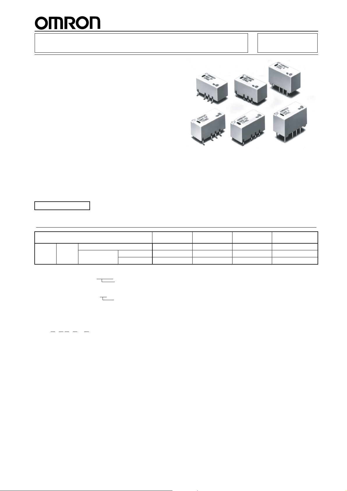
Surface Mounting DPDT Relay
■ Long terminals for ideal for soldering and mount-
ing reliability.
■ Space-saving inside-L terminal.
■ High dielectric strength between coil and contacts
(2,000 VAC), and between contacts of different
polarity (1,500 VAC).
■ High impulse withstand voltages between coil and
contacts, and between contacts of different polarity (2,500 V, 2
■ Low power consumption (140 mW).
■ Bifurcated crossbar contact (Au-clad) and Fully
sealed construction for high reliability.
■ Applicable to IRS.
■ High sealability after IRS.
■ Ultra-miniature at 15 × 7.5 × 9.4 mm (L × W × H).
■ Through-hole terminal is available
■ EN60950/EN41003 Supplementary Insulation-
certified type is available.
× 10 µs: Bellcore requirements).
G6S PCB Relay
RoHS Compliant
Refer to pages 16 to 17 for details.
Ordering Information
Classification Single-side
DPDT Fully
Note: 1. When ordering, add the rated coil voltage to the model number.
sealed
Example: G6S-2F 12 VDC
2. When ordering tape packing, add -TR" to the model number.
Example: G6S-2F-TR 12 VDC
Be sure since -TR" is not part of the relay model number, it is not marked on the relay case.
PCB terminal G6S-2 G6SU-2 G6SK-2 G6S-2-Y
Surface mount-
ing terminal
Inside-L G6S-2G G6SU-2G G6SK-2G G6S-2G-Y
Outside-L G6S-2F G6SU-2F G6SK-2F G6S-2F-Y
Rated coil voltage
Tape packing
stable
Model Number Legend
G6S@-@@-@ @ VDC
1 2 3 4 5
1. Relay Function
None: Single-side stable
U: Single-winding latching
K: Double-winding latching
2. Contact Form
2: DPDT
3. Terminal Shape
None: PCB terminal
G: Inside-L surface mounting terminal
F: Outside-L surface mounting terminal
Single-winding
latching
4. Approved Standards
None: UL/CSA
Y: EN60950/EN41003
5. Rated Coil Voltage
4.5, 5, 12, 24 VDC
Double-winding
latching
Single-side stable
EN60950/EN41003
71
G6SG6S
Specifications
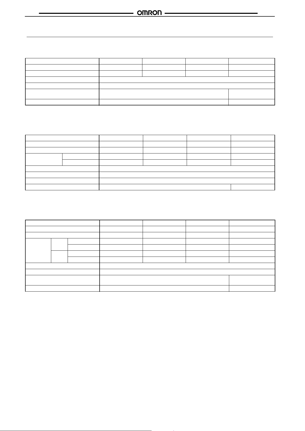
■ Coil Ratings
Single-side Stable Type (G6S-2, G6S-2F, G6S-2G)
Rated voltage 4.5 VDC 5 VDC 12 VDC 24 VDC
Rated current 31.0 mA 28.1 mA 11.7 mA 8.3 mA
Coil resistance 145
Must operate voltage 75% max. of rated voltage
Must release voltage 10% min. of rated voltage
Max. voltage 200% of rated voltage at 23°C 170% of rated voltage
Power consumption Approx. 140 mW Approx. 200 mW
Note: 1. The rated current and coil resistance are measured at a coil temperature of 23°C with a tolerance of ±10%.
2. Operating characteristics are measured at a coil temperature of 23°C.
3. The maximum voltage is the highest voltage that can be imposed on the relay coil.
Single-winding Latching Type (G6SU-2, G6SU-2F, G6SU-2G)
Rated voltage 4.5 VDC 5 VDC 12 VDC 24 VDC
Rated current 22.2 mA 20 mA 8.3 mA 6.3 mA
Coil resistance 203
Coil inductance
(H) (ref. value)
Must set voltage 75% max. of rated voltage
Must reset voltage 75% max. of rated voltage
Max. voltage 180% of rated voltage at 23°C
Power consumption Approx. 100 mW Approx. 150 mW
Note: 1. The rated current and coil resistance are measured at a coil temperature of 23°C with a tolerance of ±10%.
2. Operating characteristics are measured at a coil temperature of 23°C.
3. The maximum voltage is the highest voltage that can be imposed on the relay coil.
Armature OFF 0.27 0.36 2.12 5.80
Armature ON 0.14 0.18 1.14 3.79
Double-winding Latching Type (G6SK-2, G6SK-2F, G6SK-2G)
Ω 178 Ω 1,028 Ω 2,880 Ω
at 23°C
Ω 250 Ω 1,440 Ω 3,840 Ω
Rated voltage 4.5 VDC 5 VDC 12 VDC 24 VDC
Rated current 44.4 mA 40 mA 16.7 mA 12.5 mA
Coil resistance 101
Coil induc-
tance (H)
(ref. value)
Must set voltage 75% max. of rated voltage
Must reset voltage 75% max. of rated voltage
Max. voltage 170% of rated voltage at 23°C 140% of rated voltage
Power consumption Approx. 200 mW Approx. 300 mW
Note: 1. The rated current and coil resistance are measured at a coil temperature of 23°C with a tolerance of ±10%.
Set Armature OFF 0.12 0.14 0.60 1.98
Armature ON 0.074 0.088 0.41 1.23
Reset Armature OFF 0.082 0.098 0.46 1.34
Armature ON 0.14 0.16 0.54 2.23
2. Operating characteristics are measured at a coil temperature of 23°C.
3. The maximum voltage is the highest voltage that can be imposed on the relay coil.
Ω 125 Ω 720 Ω 1,920 Ω
at 23°C
72
G6SG6S
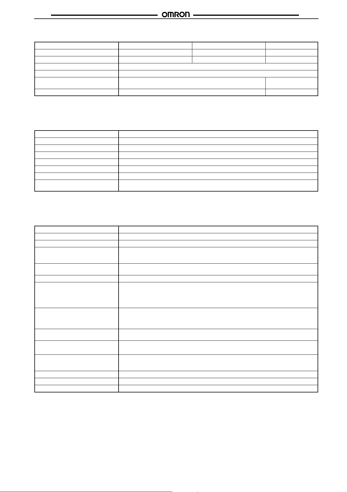
Single-side Stable EN60950/EN41003 Approved Type (G6S-2-Y, G6S-2F-Y, G6S-2G-Y)
Rated voltage 5 VDC 12 VDC 24 VDC
Rated current 40 mA 16.7 mA 9.6 mA
Coil resistance 125
Must operate voltage 75% max. of rated voltage
Must release voltage 10% min. of rated voltage
Max. voltage 170% of rated voltage at 23°C 170% of rated voltage
Power consumption Approx. 200 mW Approx. 230 mW
Note: 1. The rated current and coil resistance are measured at a coil temperature of 23°C with a tolerance of ±10%.
2. Operating characteristics are measured at a coil temperature of 23°C.
3. The maximum voltage is the highest voltage that can be imposed on the relay coil.
Contact Ratings
■
Ω 720 Ω 2,504 Ω
at 23°C
Load Resistive load (cos
Rated load 0.5 A at 125 VAC; 2 A at 30 VDC
Contact material Ag (Au-Alloy)
Rated carry current 2 A
Max. switching voltage 250 VAC, 220 VDC
Max. switching current 2 A
Max. switching power 62.5 VA, 60 W
Failure rate (reference value)
(See note.)
Note: P level: λ60 = 0.1 x 10⁻⁶/operation
This value was measured at a switching frequency of 120 operations/min and the criterion of contact resistance is 50
may vary depending on the operating environment. Always double-check relay suitability under actual operating conditions.
■
Characteristics
Contact resistance (See note 1.) 75 m
Operate (set) time (See note 2.) 4 ms max. (approx. 2.5 ms; latching type: approx. 2 ms)
Release (reset) time (See note 2.) 4 ms max. (approx. 1.5 ms; latching type: approx. 2 ms)
Bounce time Operate: Approx. 0.5 ms
Max. operating frequency Mechanical: 36,000 operations/hr
Insulation resistance (See note 3.) 1,000 M
Dielectric strength 2,000 VAC, 50/60 Hz for 1 min between coil and contacts
Impulse withstand voltage 2,500 V (2 x 10 µs) between coil and contacts
Vibration resistance Destruction: 10 to 55 to 10 Hz, 2.5-mm single amplitude (5-mm double amplitude)
Shock resistance
Endurance Mechanical: 100,000,000 operations min. (at 36,000 operations/hr)
Ambient temperature Operating:
Ambient humidity Operating: 5% to 85%
Weight Approx. 2 g
Note: The above values are initial values.
Note: 1. The contact resistance was measured with 10 mA at 1 VDC with a voltage drop method.
2. Values in parentheses are actual values.
3. The insulation resistance was measured with a 500-VDC megohmmeter applied to the same parts as those used for checking
the dielectric strength (except between the set and reset coil).
10 µA at 10 mVDC
Ω max.
Release: Approx. 0.5 ms
Set/Reset: Approx. 0.5 ms
Electrical: 1,800 operations/hr (under rated load)
Ω min. (at 500 VDC)
1,000 VAC, 50/60 Hz for 1 min between coil and contacts (double-winding latching)
1,500 VAC, 50/60 Hz for 1 min between contacts of different polarity
1,000 VAC, 50/60 Hz for 1 min between contacts of same polarity
500 VAC, 50/60 Hz for 1 min between set and reset coil (double-winding latching)
1,500 V (10 x 160 µs) between coil and contacts (double-winding latching)
2,500 V (2 x 10 µs) between contacts of different polarity
1,500 V (10 x 160 µs) between contacts of same polarity (conforms to FCC Part 68)
Malfunction: 10 to 55 to 10 Hz, 1.65-mm single amplitude (3.3-mm double amplitude)
Destruction: 1,000 m/s
Malfunction: 750 m/s
Electrical: 100,000 operations min. (2 A at 30 VDC, resistive load: 1,200 operations/hr)
100,000 operations min. (0.5 A at 125 VAC, resistive load)
φ = 1)
2
(approx. 100G)
2
(approx. 75G)
−40°C to 85°C (with no icing), −40°C to 70°C (double-winding latching, 24 VDC)
Ω. This value
73

■ Approved Standards
UL1950 (File No. E41515)/CSA C22.2 No.950 (File No. LR31928)
Model Contact form Coil ratings Contact ratings
G6S-2, G6S-2F, G6S-2G DPDT 1.5 to 48 VDC 2 A, 30 VDC
G6SU2, G6SK-2, G6SU-2F,
G6SU2G, G6SK-2F, G6SK-2G
1.5 to 24 VDC
0.3 A, 110 VDC
0.5 A, 125 VAC
EN60950/EN41003
Model Contact form Isolation category Voltage
G6S-2-Y, G6S-2G-Y, G6S-2F-Y DPDT Supplementary Isolation 250 VAC
G6SG6S
74

Engineering Data
G6SG6S
Maximum Switching Power
Ambient Temperature vs.
Maximum Coil Voltage
Single-side Stable
AC resistive load
Switching current (A)
DC resistive load
Maximum coil voltage (%)
Switching voltage (V) Ambient temperature (°C)
Note: The maximum coil voltage refers to the maximum value in a varying range of
Reference Data
operating power voltage, not a continuous voltage.
Ambient Temperature vs. Switching Current
Single-side Stable
24 VDC
(G6S-Y)
Switching current (A)
24 VDC
(G6S-Y, 12 VDC
max.)
12 VDC max.
Single-winding Latching
Double-winding Latching
Operating current (A)
12 VDC max.
24 VDC
(G6S-Y, 12 VDC max.)
24 VDC
(G6S-Y)
Ambient temperature (°C)
G6SU
12 VDC max.
G6SU
24 VDC
G6SK
12 VDC max.
G6SK
24 VDC
Single-winding Latching
Double-winding Latching
G6SK
12 VDC
max.
G6SK
24 VDC
Maximum coil voltage (%)
G6SU
Ambient temperature (°C)
Ambient temperature (°C)
Recommended Soldering Time vs. Surface PCB Temperature
(1) IRS Method (Mounting Solder: Lead)
Soldering
220 to
Soldering
240
180 to
200
Preheating
Temperature (°C)
150
Preheating
90 to 120
20 to 30
Time (s)
(2) IRS Method (Mounting Solder: Lead-free)
250 max.
230
180
150
Temperature (°C)
Note: The temperature profile indicates the
temperature of the relay terminal section.
Upper surface of case (peak):
255˚C max.
Soldering
Preheating
Relay
terminal
section
120 max.
30 max.
Time (s)
75

Dimensions
Note: All units are in millimeters unless otherwise indicated.
Single-side Stable
G6S-2, G6S-2-Y
Tolerance: ±0.3
Footprint
(Bottom View)
Tolerance: ±0.1
Eight, 1-dia. holes Orientation mark
Terminal Arrangement/
Internal Connections
(Bottom View)
G6SG6S
G6S-2F, G6S-2F-Y
Tolerance: ±0.3
G6S-2G, G6S-2G-Y
Tolerance: ±0.3
Footprint
(Top View)
Tolerance: ±0.1
Footprint
(Top View)
Tolerance: ±0.1
Terminal Arrangement/
Internal Connections
(Top View)
Orientation mark
Terminal Arrangement/
Internal Connections
(Top View)
Orientation mark
76

Single-winding Latching
G6SU-2
Tolerance: ±0.3
Footprint
(Bottom View)
Tolerance: ±0.1
Eight, 1-dia. holes
Terminal Arrangement/
Internal Connections
(Bottom View)
Orientation mark
G6SG6S
G6SU-2F
Tolerance: ±0.3
G6SU-2G
Tolerance: ±0.3
7.3+0.2
7.3+0.2
Footprint
(Top View)
Tolerance: ±0.1
Footprint
(Top View)
Tolerance: ±0.1
Terminal Arrangement/
Internal Connections
(Top View)
Orientation mark
Terminal Arrangement/
Internal Connections
(Top View)
Orientation mark
77

Double-winding Latching
G6SK-2
Tolerance: ±0.3
G6SK-2F
Tolerance: ±0.3
Footprint
(Bottom View)
Tolerance: ±0.1
Ten, 1-dia. holes Orientation mark
Footprint
(Top View)
Tolerance: ±0.1
Terminal Arrangement/
Internal Connections
(Bottom View)
Terminal Arrangement/
Internal Connections
(Top View)
Orientation mark
G6SG6S
G6SK-2G
Tolerance: ±0.3
7.3+0.2
Footprint
(Top View)
Tolerance: ±0.1
Terminal Arrangement/
Internal Connections
(Top View)
Orientation mark
78

■ Tape Packing
When ordering, add “-TR” before the rated coil voltage for tape packing.
Tape type: TE2416R (Refer to EIAJ)
Reel type: R24E (Refer to EIAJ)
Relays per reel: 400
2±0.3
29.5±1.0
25.5±0.5
G6S-2F, G6SU-2F, G6SK-2F, G6S-2F-Y
G6SG6S
2±10.5
R1.0
13±0.2
Carrier tape
Orientation mark
Cover tape
Emboss tape
330
80
Feed direction
Precautions
Use a DC power supply with 5% or less ripple factor to operate
the coil.
Do not use the G6S where subject to strong external magnetic
fields.
Do not use the G6S where subject to magnetic particles or excessive amounts of dust.
Do not reverse the polarity of the coil (+,
Latching types are delivered in the reset position. We recommend
that a reset voltage be applied in advance to start operation.
Do not drop the G6S or otherwise subject it to excessive shock.
Remove the relay from the packing immediately prior to usage.
Precautions
■
Long-term Continuously ON Contacts
Using the Relay in a circuit where the Relay will be ON continuously for long periods (without switching) can lead to unstable
contacts because the heat generated by the coil itself will affect
the insulation, causing a film to develop on the contact surfaces.
We recommend using a latching relay (magnetic-holding relay) in
this kind of circuit. If a single-side stable model must be used in
this kind of circuit, we recommend using a fail-safe circuit design
that provides protection against contact failure or coil burnout.
Relay Handling
Use the Relay as soon as possible after opening the moistureproof package. If the Relay is left for a long time after opening the
moisture-proof package, the appearance may suffer and seal failure may occur after the solder mounting process. To store the
Relay after opening the moisture-proof package, place it into the
original package and sealed the package with adhesive tape.
−).
G6S-2G, G6SU-2G, G6SK-2G, G6S-2G-Y
When washing the product after soldering the Relay to a PCB,
use a water-based solvent or alcohol-based solvent, and keep the
solvent temperature to less than 40
°C. Do not put the Relay in a
cold cleaning bath immediately after soldering.
G6S (K) (-U) -2 Soldering
• Soldering temperature: Approx. 250°C (At 260°C if the DWS
method is used.)
• Soldering time: Approx. 5 s max. (Approx. 2 s for the first time
and approx. 3 s for the second time if the DWS method is used.)
• Be sure to adjust the level of the molten solder so that the solder
will not overflow onto the PCB.
Claw Securing Force During Automatic Mounting
During automatic insertion of Relays, be sure to set the securing
force of each claw to the following so that the Relay’s characteristics will be maintained.
C
A
Dimension A: 1.96 N max.
Dimension B: 4.90 N max.
Dimension C: 1.96 N max.
B
79

G6SG6S
ALL DIMENSIONS SHOWN ARE IN MILLIMETERS.
To convert millimeters into inches, multiply by 0.03937. To convert grams into ounces, multiply by 0.03527.
Cat. No. K093-E1-03
80
 Loading...