

Page 1
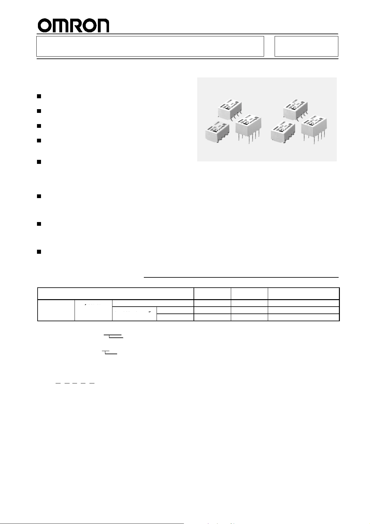
Surface Mounting Relay G6K
yseae
d
Saceo
g
Surface Mounting Relay with the
World’s Smallest Mounting Area and a
Height of Only 5.2 mm
Subminiature model as small as 5.2 (H) x 6.5 (W) x
10 (L) mm is ideal for high-density mounting.
Low profile of 5.2 mm and weight of only 0.7 g
combine to improve mounting efficiency.
Models with inside-L surface mounting terminals
are available.
Consumes approximately 70% the power of a
conventional OMRON model and operates at a
current that is as low as 100 mW.
Surface mounting terminal models incorporate a
unique terminal structure with high infrared
irradiation efficiency which allows the terminal
temperature to rise easily when mounting the IRS,
thus ensuring excellent soldering.
Ensures a dielectric strength of 1,500 VAC and
conforms to FCC Part 68 (i.e., withstanding an
impulse withstand voltage of 1,500 V for 10 x
160 !s).
New-Y models offer an impulse withstand voltage
of 2,500 V for 2 x 10 !s (conforms to Bellcore
specifications) by optimizing the distance between
coil and contacts.
Conforms toUL1950(FileNo. E41515)/CSA C22.2
No. 950 (File No. LR24825)
The above specifications are ensured as of August 1999.
RC
Ordering Information
Classification Single-side
DPDT Fully sealed
1. When ordering, add the rated coil voltage to the model number.
Note:
Example: G6K-2F 12 VDC
2. When ordering tape packing, add “-TR” to the model number.
Example: G6K-2F-TR 12 VDC
Be sure since “-TR” is not part of the relay model number, it is not marked on the relay case.
Model Number Legend
G6Kj-
1. Relay function
None: Single-side stable model
2. Contact form
jj-jj
1234 5
U: Single-winding latching model
2: DPDT
Through-hole terminal
Surface mounting
terminal
Tape packing
VDC
Rated coil voltage
Inside-L
Outside-L
stable
G6K-2P G6KU-2P-Y G6K-2P-Y
G6K-2G G6KU-2G-Y G6K-2G-Y
G6K-2F G6KU-2F-Y G6K-2F-Y
3. Terminal shape
F: Outside-L surface mounting terminal
G: Inside-L surface mounting terminal
P: PCB terminal
4. Approved standards
None: UL, CSA
Y: UL, CSA
5. Rated Coil Voltage
3, 4.5, 5, 12, 24 VDC
Single-winding
latching
Does not conform to Bellcore specifications
ConformstoBellcorespecifications: 2,500Vfor2x10!s
Single-side stable Bellcore:
2, 500 V for 2x10!s
1
Page 2
G6K
Application Examples
Telephones, communications equipment, measurement devices, office automation machines, and audio-visual products.
Specifications
Contact mechanism: Bifurcated crossbar Ag (Au-alloy contact)
Enclosure ratings: Fully sealed
Coil Ratings
Single-side Stable Models
G6K-2F, G6K-2G, G6K-2P
Rated voltage
Rated current
Coil resistance
Must operate voltage
Must release voltage
Max. voltage
Power consumption
1. The rated current and coil resistance are measured at a coil temperature of 23#C with a tolerance of$10%.
Note:
2. The operating characteristics are measured at a coil temperature of 23#C.
3. The maximum voltage is the highest voltage that can be imposed on the relay coil instantaneously.
Single-side Stable Models (Bellcore Version)
G6K-2F-Y, G6K-2G-Y, G6K-2P-Y
Rated voltage
Rated current
Coil resistance
Must operate voltage
Must release voltage
Max. voltage
Power consumption
1. The rated current and coil resistance are measured at a coil temperature of 23#C with a tolerance of$10%.
Note:
2. The operating characteristics are measured at a coil temperature of 23#C.
3. The maximum voltage is the highest voltage that can be imposed on the relay coil instantaneously.
3VDC 4.5 VDC 5VDC 12 VDC
33.0 mA 23.2 mA 21.1 mA 9.1 mA
91
"
80% max. of rated voltage
10% min. of rated voltage
150% of rated voltage at 23#Cto70#C
Approx. 100 mW
3VDC 4.5 VDC 5VDC 12 VDC 24 VDC
33.0 mA 23.2 mA 21.1 mA 9.1 mA 4.6 mA
91
"
80% max. of rated voltage
10% min. of rated voltage
150% of rated voltage at 23#Cto70#C
Approx. 100 mW
194
194
"
"
237
237
"
"
1,315
1,315
"
"
5,220
G6K
"
2
Page 3
G6K
p
Single-winding Latching Models (Bellcore Version)
G6KU-2F-Y, G6KU-2G-Y, G6KU-2P-Y
Rated voltage
Rated current
Coil resistance
Must set voltage
Must reset voltage
Max. voltage
Power consumption
1. The rated current and coil resistance are measured at a coil temperature of 23#C with a tolerance of$10%.
Note:
2. The operating characteristics are measured at a coil temperature of 23#C.
3. The maximum voltage is the highest voltage that can be imposed on the relay coil instantaneously.
3VDC 4.5 VDC 5VDC 12 VDC 24 VDC
33.0 mA 23.2 mA 21.1 mA 9.1 mA 4.6 mA
91
"
75% max. of rated voltage
75% max. of rated voltage
150% of rated voltage at 23#Cto70#C
Approx. 100 mW
194
"
237
"
1,315
Contact Ratings
Load
Rated load
Rated carry current
Max. switching voltage
Max. switching current
Resistive load
0.3 A at 125 VAC; 1 A at 30 VDC
1A
125 VAC, 60 VDC
1A
Characteristics
Item
Contact resistance (see note 1)
Operating (set) time (see note 2)
Release (reset) time (see note 2)
Insulation resistance (see note 3)
Dielectric
strength
Impulse
withstand
voltage
Vibration resistance
Shock resistance
Life expectancy
Failure rate (P level) (see note 4)
Ambient temperature
Ambient humidity
Weight
Coil and contacts
Contacts of different
polarity
Contacts of same
polarity
Coil and contacts
Contacts of different
polarity
Contacts of same
polarity
100 m"max.
3 ms max. (approx. 1.4 ms) 3 ms max. (approx. 1.2 ms)
3 ms max. (approx. 1.3 ms) 3 ms max. (approx. 1.2 ms)
1,000 M"min. (at 500 VDC)
1,500 VAC, 50/60 Hz for 1 min
1,000 VAC, 50/60 Hz for 1 min
750 VAC, 50/60 Hz for 1 min
1,500 V (10 x 160!s) 2,500 V (2 x 10!s), 1,500 V (10 x 160!s)
1,500 V (10 x 160!s)
Destruction: 10 to 55 Hz, 5-mm double amplitude and 55 to 500 Hz, 300 m/s2(approx. 30G)
Malfunction: 10 to 55 Hz, 3.3-mm double amplitude and 55 to 500 Hz, 200 m/s
Destruction: 1,000 ms2(approx. 100G)
Malfunction: 750 ms
Mechanical: 50,000,000 operations min. (at 36,000 operations/hour)
Electrical: 100,000 operations min. (with a rated load at 1,800 operations/hour)
10!Aat10mVDC
Operating: --40#Cto70#C (with no icing or condensation)
Storage: --40#Cto70#C (with no icing or condensation)
Operating: 35 to 85%
Approx. 0.7 g
Single-side stable models (double-pole) Single-winding latching
G6K-2F, G6K-2G, G6K-2P G6K-2F-Y, G6K-2G-Y,
2
(approx. 75G)
G6K-2P-Y
"
G6KU-2F-Y, G6KU-2G-Y,
5,220
model
G6KU-2P-Y
2
(approx. 20G)
"
G6K
The above values are initial values.
Note:
1. The contact resistance was measured with 10 mA at 1 VDC with a fall-of-potential method.
Note:
2. Values in parentheses are actual values.
3. Theinsulationresistancewas measuredwitha 500-VDCmeggerappliedtothesame partsasthoseused forcheckingthedielectric
strength.
4. This value was measured at a switching frequency of 120 operations/min.
3
Page 4
G6K
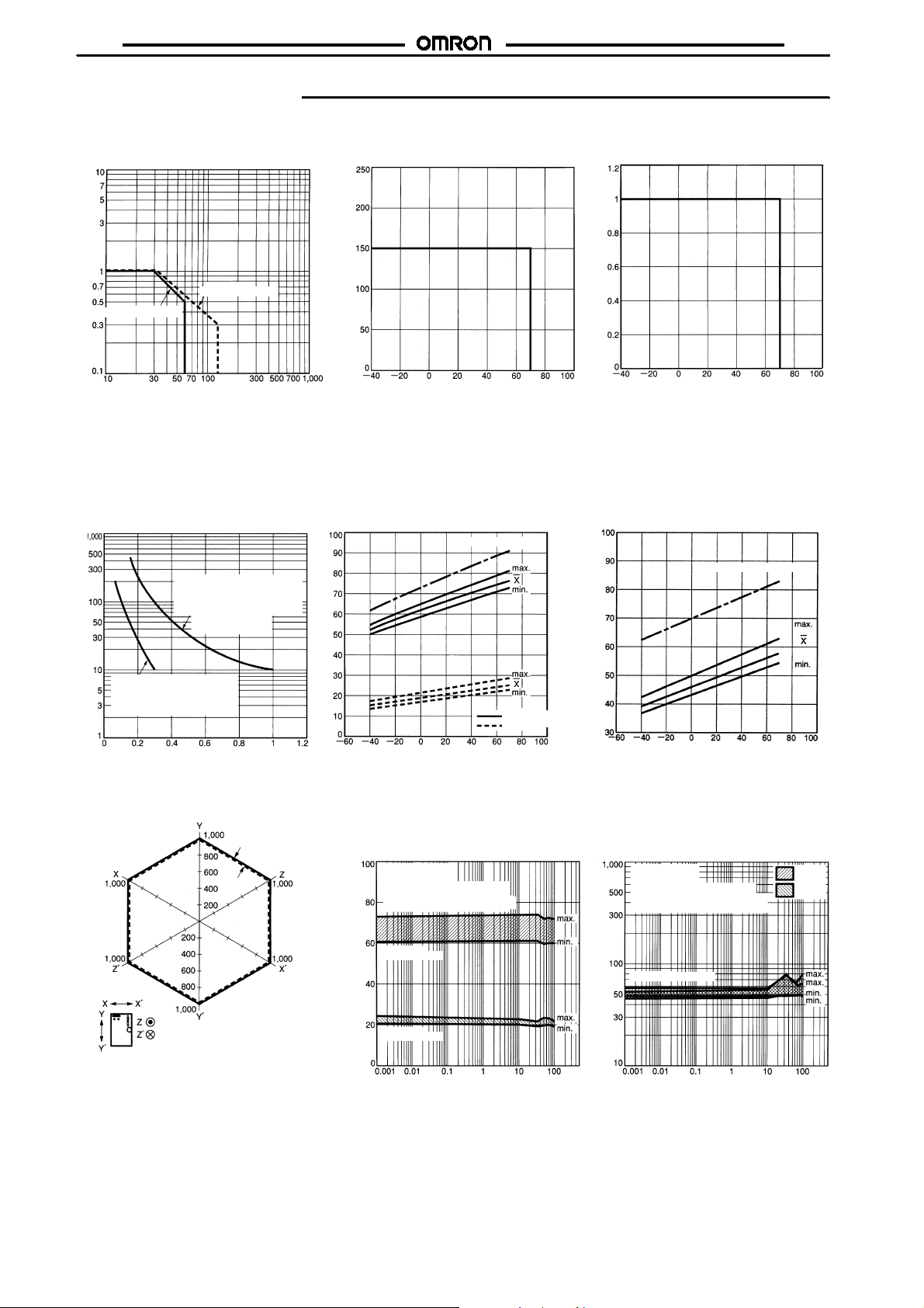
Engineering Data
G6K
Maximum Switching Power Ambient Temperature vs.
Maximum Coil Voltage
Switching current (A)
DC resistive load
AC resistive load
Switching voltage (V)
Maximum coil voltage (%)
Ambient temperature (#C)
Themaximum coilvoltage refers tothemaxi-
Note:
mum value in a varying range of operating
power voltage, not a continuous voltage.
Life Expectancy Ambient Temperature vs. Must
Operate or Must Release Voltage
G6K-2G (F/P), G6K-2G (F/P)-Y
Max. estimated value
30 VDC resistive load
4
Ambient temperature: 23#C
Switching frequency:
1,800 operations/hour
Ambient Temperature vs.
Switching Current
Switching current (A)
Ambient temperature (#C)
Ambient Temperature vs. Must
Set or Must Reset Voltage
G6KU-2G (F/P)-Y
Max. estimated value
125 VAC resistive load
Ambient temperature: 23#C
Switching frequency:
1,800 operations/hour
Switching operations (x10 operations)
Switching current (A)
Shock Malfunction
Energized
Not
energized
Shock direction
Conditions: Shock is applied in$X,$Y, and$Z
directions three times each with and
without energizing the Relays to check
the number of contact malfunctions.
Unit: m/s
Sample: G6K-2G
Number of Relays: 10
On the basis of rated voltage (%)
Ambient temperature (#C)
Electrical Life Expectancy
(with Must Operate and Must
Release Voltage) (see note)
Must operate voltage
Must release voltage
On the basis of rated voltage (%)
Ambient temperature (#C)
Electrical Life Expectancy
(Contact Resistance) (see note)
G6K-2G (F/P), G6K-2G (F/P)-Y
G6K-2G (F/P), G6K-2G (F/P)-Y
Sample: G6K-2G
Number of Relays: 10
Testconditions: 1 A resistive load at
30 VDC with an operation rate of 50%
Switching frequency: 1,800 operations/h
Must operate
2
Must release
Sample: G6K-2G
"
Number of Relays: 10
Testconditions: 1 A resistive load
at 30 VDC with an operation rate of 50%
Switching frequency: 1,800 operations/h
Contact resistance
Contact resistance (m )
On the basis of rated voltage (%)
Operating frequency (x103operations)
Operating frequency (x103operations)
NO
contact
NC
contact
4
Page 5
G6K
G6K
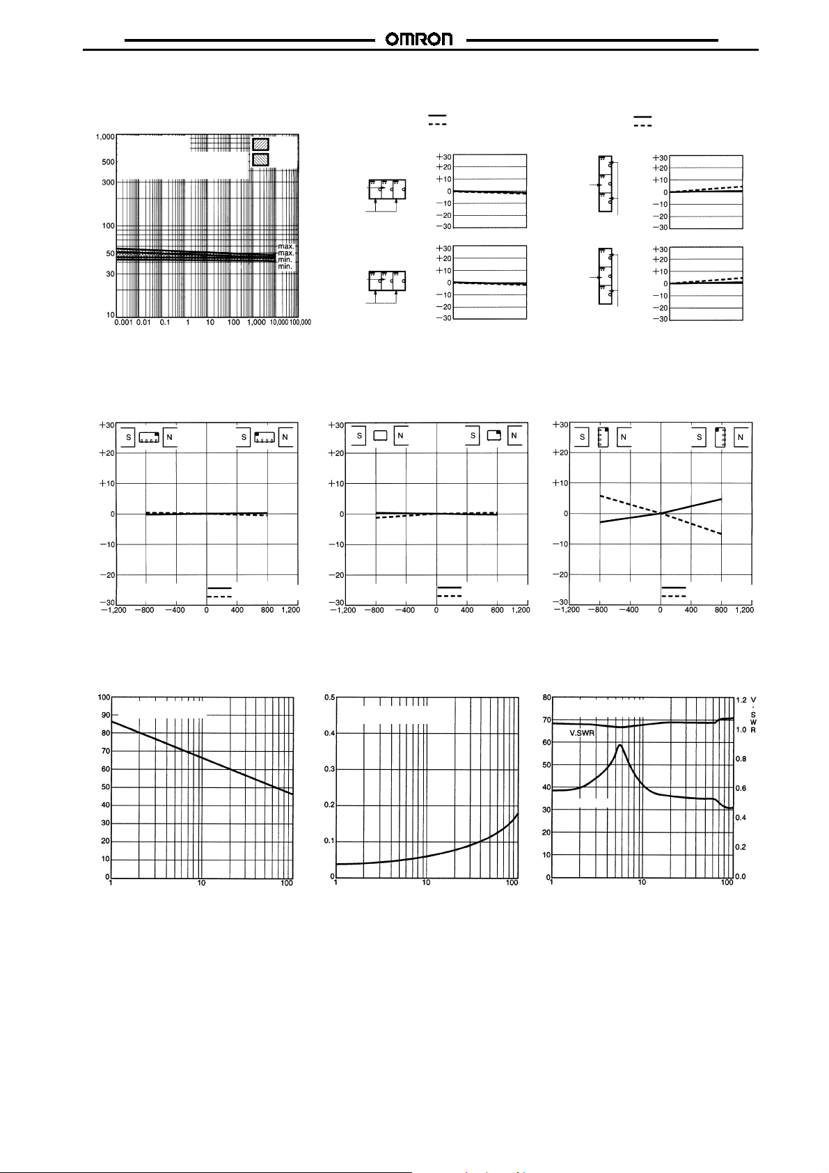
Contact Reliability Test
(see note)
G6K-2G (F/P), G6K-2G (F/P)-Y
Sample: G6K-2G
"
Number of Relays: 10
Testconditions: 10!A resistive load at
10 mVDC with an operation rate of 50 %
Switching frequency: 7,200 operations/h
Contact resistance (m )
Operating frequency (x103operations)
The test was conducted at an
Note:
ambient temperature of 23#C.
External Magnetic Interference
G6K-2G (F/P), G6K-2G (F/P)-Y
(Average value)
NO
contact
NC
contact
Mutual Magnetic Interference
G6K-2G (F/P), G6K-2G (F/P)-Y
Must operate voltage
Must release voltage
Initial stage Test
Sample
Not energized
Sample
Energized
Change rate on the basis
Change rate on the basis
Average value
of initial value (%)
Initial stage
Average value
of initial value (%)
(Average value)
Mutual Magnetic Interference
G6K-2G (F/P), G6K-2G (F/P)-Y
Must operate voltage
Must release voltage
Initial stage
Sample
Not energized
Test
Sample
Energized
Change rate on the basis
of initial value (%)
Change rate on the basis
of initial value (%)
Average value
Initial stage
Average value
(Average value)
Test
Test
Sample: G6K-2G
Number of Relays: 10
Change rate on the basis of initial value (%)
External magnetic field (A/m)
Must operate voltage
Must release voltage
High-frequency Characteristics
(Isolation)
G6K-2G (F/P), G6K-2G (F/P)-Y
(Average value)
Sample: G6K-2G
Number of Relays: 10
Isolation (dB)
Frequency (MHz)
Sample: G6K-2G
Number of Relays: 10
Change rate on the basis of initial value (%)
External magnetic field (A/m)
Must operate voltage
Must release voltage
High-frequency Characteristics
(Insertion Loss)
G6K-2G (F/P), G6K-2G (F/P)-Y
(Average value)
Sample: G6K-2G
Number of Relays: 10
Insertion loss (dB)
Frequency (MHz)
Sample: G6K-2G
Number of Relays: 10
Change rate on the basis of initial value (%)
External magnetic field (A/m)
Must operate voltage
Must release voltage
High-frequency Characteristics
(Return Loss)
G6K-2G (F/P),G6K-2G (F/P)-Y
(Average value)
Sample: G6K-2G
Number of Relays: 10
Return loss (dB)
Return loss
Frequency (MHz)
5
Page 6
G6K
G6K
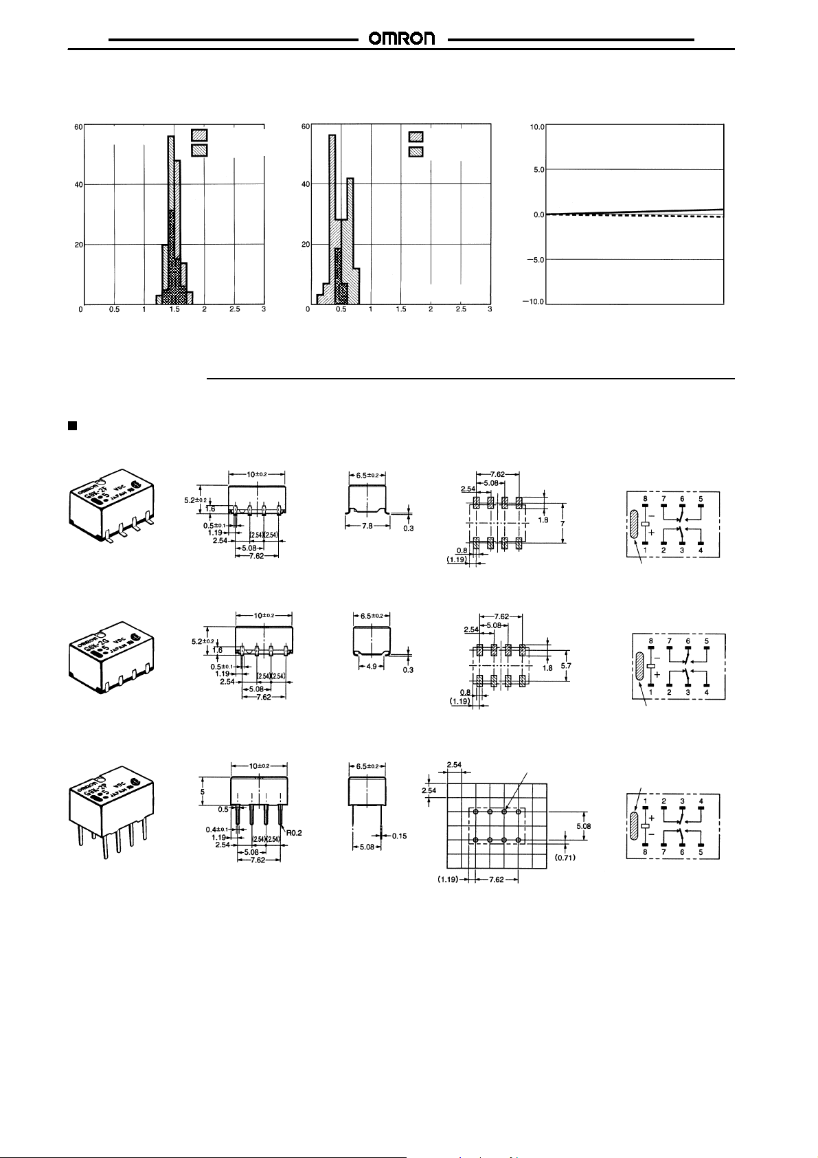
Must Operate and Must Release
Time Distribution
G6K-2G (F/P), G6K-2G (F/P)-Y
Sample: G6K-2G
Number of Relays: 50
Number of contacts
Thetests were conductedatan ambient temperatureof23#C.
Note:
(see note)
Must operate
Must release time
Time (ms)
Must Operate and Must Release
Bounce Time Distribution
G6K-2G (F/P) , G6K-2G (F/P)-Y
Number of contacts
Dimensions
All units are in millimeters unless otherwise indicated.
Note:
DPDT
G6K-2F
Vibration Resistance
(see note)
Must operate
bounce time
Must release
bounce time
Sample: G6K-2G
Number of Relays: 50
Time (ms)
Mounting Dimensions (Top View) Terminal Arrangement/
Tolerance:$0.1 mm
G6K-2G (F/P), G6K-2G (F/P)-Y
Must operate voltage
Must release voltage
Change rate on the basis of rated value (%)
Internal Connections
(Top View)
After test
G6K-2G
G6K-2P
Each value has a tolerance of$0.3 mm.
Note:
Each value has a tolerance of$0.3 mm.
Note:
Each value has a tolerance of$0.3 mm.
Note:
Orientation mark
Mounting Dimensions (Top View) Terminal Arrangement/
Tolerance:$0.1 mm
Mounting Dimensions (Bottom View) Terminal Arrangement/
Tolerance:$0.1 mm
Eight, 0.8-dia. holes
Internal Connections
(Top View)
Orientation mark
Internal Connections
(Bottom View)
Orientation mark
6
Page 7
G6K
G6K
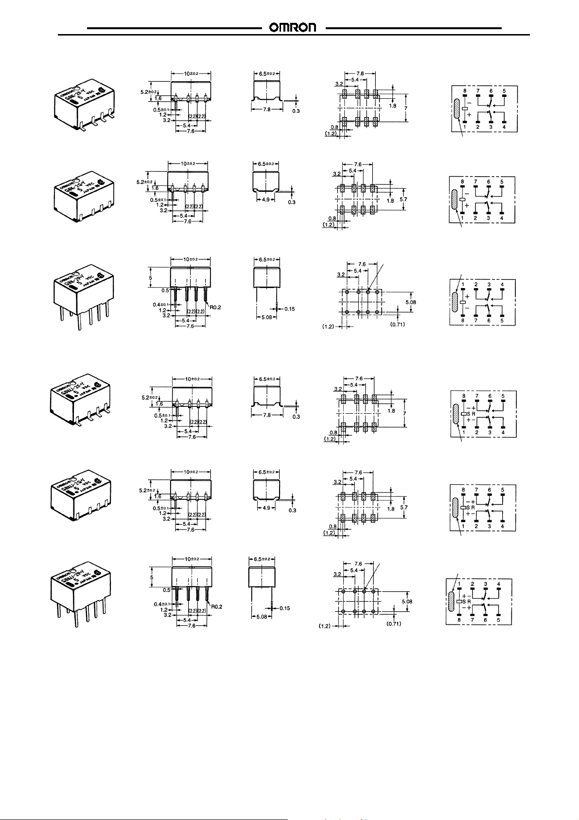
G6K-2F-Y
G6K-2G-Y
G6K-2P-Y
Each value has a tolerance of$0.3 mm.
Note:
Each value has a tolerance of$0.3 mm.
Note:
Each value has a tolerance of$0.3 mm.
Note:
Mounting Dimensions (Top View) Terminal Arrangement/
Tolerance:$0.1 mm
Mounting Dimensions (Top View) Terminal Arrangement/
Tolerance:$0.1 mm
Mounting Dimensions (Bottom View) Terminal Arrangement/
Tolerance:$0.1 mm
Eight, 0.8-dia. holes
Internal Connections
(Top View)
Orientation mark
Internal Connections
(Top View)
Orientation mark
Internal Connections
(Bottom View)
Orientation mark
G6KU-2F-Y
G6KU-2G-Y
G6KU-2P-Y
Each value has a tolerance of$0.3 mm.
Note:
Each value has a tolerance of$0.3 mm.
Note:
Each value has a tolerance of$0.3 mm.
Note:
Mounting Dimensions (Top View)
Tolerance:$0.1 mm
Mounting Dimensions (Top View) Terminal Arrangement/
Tolerance:$0.1 mm
Mounting Dimensions (Bottom View) Terminal Arrangement/
Tolerance:$0.1 mm
Eight, 0.8-dia. holes
Terminal Arrangement/
Internal Connections
(Top View)
Orientation mark
Internal Connections
(Top View)
Orientation mark
Internal Connections
(Bottom View)
Orientation mark
7
Page 8
G6K
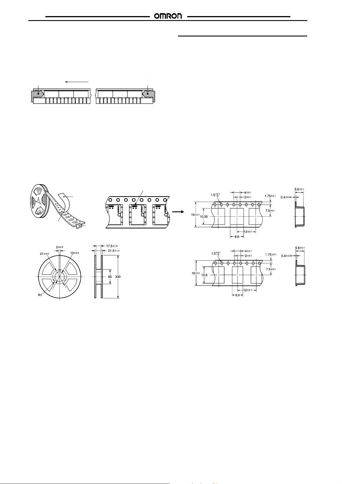
Stick Packing and Tape Packing
Stick Packing
Relays in stick packing arearranged sothat theorientation markof
eachRelay in on theleft side. Fifty Relays arepacked on one stick.
Be sure not to make mistakes in Relay orientation when mounting
the Relay to the PCB.
Stopper (gray)
Stick length: 520 mm (stopper not included)
No. of Relays per stick: 50
Tape Packing (Surface Mounting Terminal Models)
When ordering Relays in tape packing, add the prefix “-TR” to the
model number, otherwise the Relays in stick packing will be provided.
Tape Type: ETX7200
Reel type: RPM-16D (EIAJ)
Relays per Reel: 900
1. Direction of Relay Insertion
Orientation of Relays
(EIAJ (Electronic Industrial Association of Japan))
Top tape (cover tape)
Stopper (green)
Pulling direction
Orientation mark
3. Carrier Tape Dimensions
G6K-2F, G6K-2F-Y,G6KU-2F-Y
G6K
Carrier tape
2. Reel Dimensions
Pulling direction
Emboss tape
G6K-2G, G6K-2G-Y,G6KU-2G-Y
8
Page 9
G6K
)
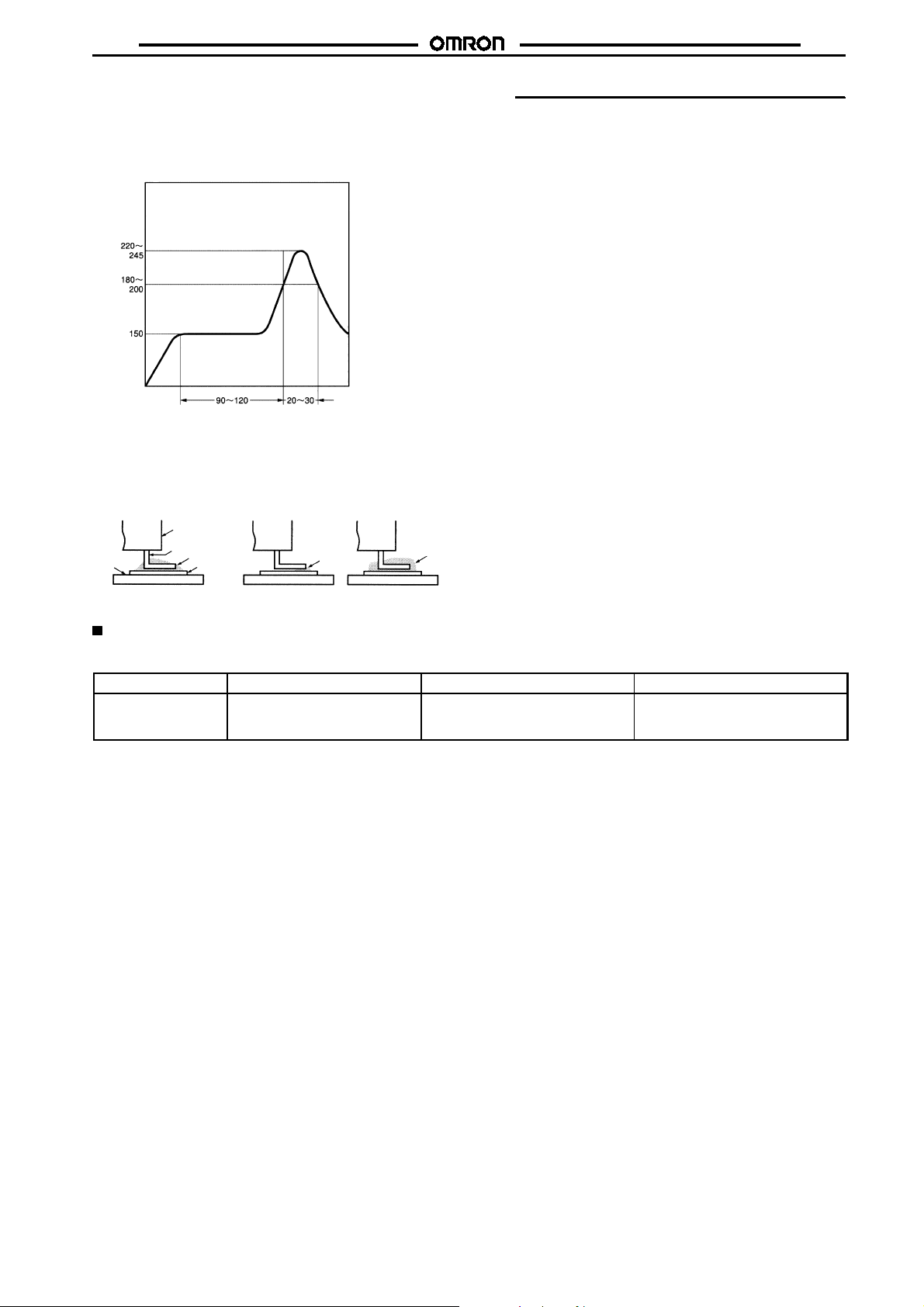
Recommended Soldering Method
Temperatures indicate the surface temperatures of the PCB.
IRS Method (for surface mounting terminal models)
#
Soldering
Temperature ( C)
Preheating
Time(s
Thethickness ofcream solder tobeapplied should bewithin a range between150 and 200!mon OMRON’s recommended PCB pattern.
%
Inorder toperformcorrectsoldering,itisrecommendedthatthe correct soldering conditionsbe maintained asshownbelowontheleft-hand
%
side.
G6K
Correct Soldering
Relay
Terminal
PCB
Visually check that the Relay is properly soldered.
Solder
Land
Incorrect Soldering
Insufficient
amount of
solder
Approved Standards
UL approval: UL1950(File No. E41515)
CSA approval: C22.2 No. 950 (File No. LR24825)
Contact form
DPDT G6K-2G(F/P): 3to12VDC
G6K(U)-2G(F/P)-Y: 3 to 24 VDC
Coil rating Contact rating Number of test operations
Excessive
amount of
solder
1 A at 30 VDC
0.5 A at 60 VDC
0.3 A at 125 VAC
6,000
9
Page 10
G6K
Precautions
For general precautions, refer to the
Familiarizeyourself with theprecautionsandglossary before using
the G6K.
Correct Use
Handling
Leave the Relay unpacked until mounting it.
Soldering
Solder: JIS Z3282, H63A
Solderingtemperature:Approx. 250#C(260#CiftheDWSmethodis
used)
Soldering time: Approx. 5 s max. (approx. 2 s for the first time and
approx. 3 s for the second time if the DWS method is used)
Besureto make a moltensolderlevel adjustmentsothat the solder
will not overflow on the PCB.
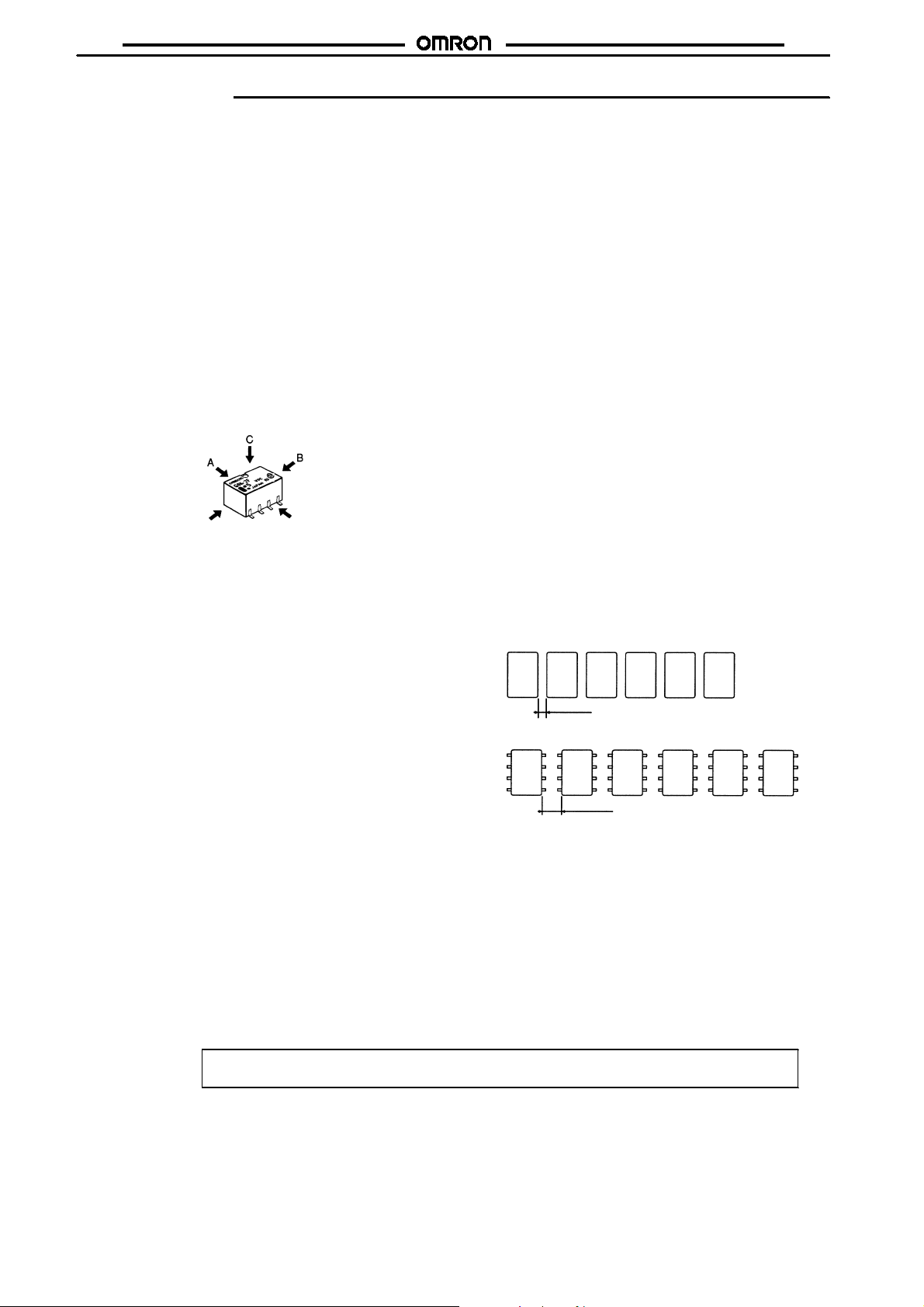
Claw Securing Force During Automatic Mounting
Duringautomatic insertionofRelays, make sure toset thesecuring
forceofeachclawtothefollowingsothattheRelayscharacteristics
will be maintained.
Direction A: 1.96 N
Direction B: 4.90 N
Direction C: 1.96 N
Environmental Conditions During Operation, Storage, and
Transportation
ProtecttheRelayfrom direct sunlight andkeeptheRelayundernormal temperature, humidity, and pressure.
If the Relay isstored for a longtime in an adverseenvironment with
high temperature, high humidity, organic gases, or sulfide gases,
sulfide or oxide films will form on the contact surfaces. These films
mayresult inunstablecontact,contactproblems,orfunctionalproblems. Therefore, operate, store,ortransporttheproduct underspecified environmental conditions.
Latching Relay Mounting
Make sure that the vibration or shock that is generated from other
devices, such as relays in operation, on the same panel and imposed on the Latching Relay does not exceed the rated value,
otherwisetheLatchingRelaythathasbeenset may be reset or vice
versa. The Latching Relay is reset before shipping. If excessive
vibration or shockis imposed,however,theLatching Relay maybe
set accidentally. Be sure to apply a reset signal before use.
PCB Relays Catalog (X033)
.
Maximum Allowable Voltage
Themaximumallowablevoltageof thecoilcanbe obtained fromthe
coiltemperatureincrease andtheheat-resisting temperatureof coil
insulating sheathmaterial. (Exceeding the heat-resisting temperature may result in burningor short-circuiting.) The maximum allowable voltage also involves important restrictions which include the
following:
Must not cause thermal changes in or deterioration of the
%
insulating material.
Must not cause damage to other control devices.
%
Must not cause any harmful effect on people.
%
Must not cause fire.
%
Therefore, be sure to use the maximum allowable voltage beyond
the value specified in the catalog.
Asarule,theratedvoltagemust be applied to the coil. A voltageexceeding the rated value, however, can be applied to the coil providedthatthe voltage is less thanthemaximumallowablevoltage.It
must be noted that continuous voltage application to the coil will
cause a coil temperature increase thus affecting characteristics
suchas electrical lifeandresultinginthedeterioration of coil insulation.
Coating
The Relay mounted on the PCB may be coated or washed but do
not apply silicone coating or detergent containing silicone, otherwisethe silicone coatingor detergent may remainon thesurface of
the Relay.
PCB Mounting
Iftwoormore Relays are closelymounted with thelongsides of the
Relays facing each other and soldering is performed with infrared
radiation, the solder may not be properly exposed to the infrared
rays. Be sure to keep theproperdistance between adjacentRelays
as shown below.
G6K-2G
2mmmin.
G6K-2F
2.7 mm min.
Twoor more Relays may becloselymounted with theshort sides of
the Relays facing each other.
G6K
Cat. No. K106-E1-3A
10
ALL DIMENSIONS SHOWN ARE IN MILLIMETERS.
To convert millimeters into inches, multiply by 0.03937. To convert grams into ounces, multiply by 0.03527.
 Loading...