

Page 1
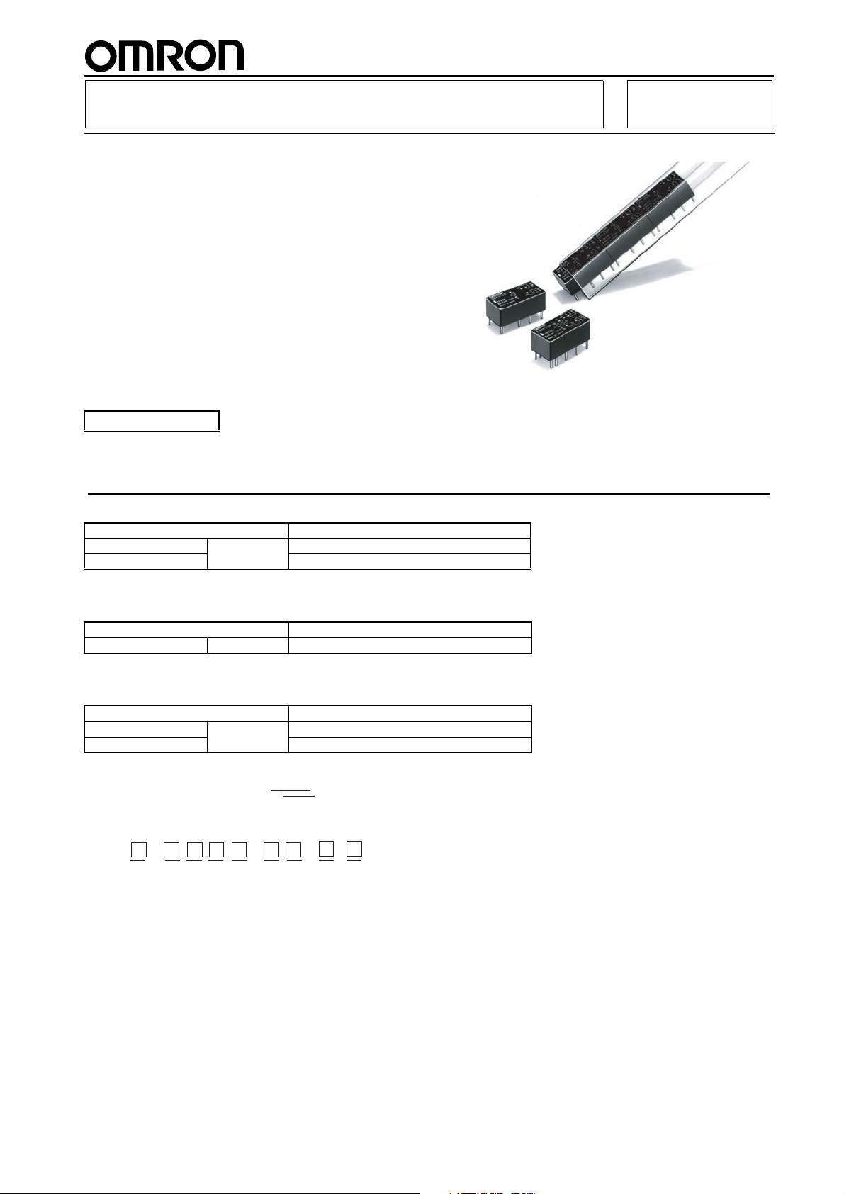
Fully Sealed Relay with High Impulse
Dielectric for Use in
Telecommunications Equipment
■ High sensitivity can be driven by digital circuits.
■ Horizontal design allows use in 1/2-inch PCB
racks.
■ Impulse withstand voltage meets FCC Part 68
requirements.
■ Relays can be mounted side-by-side due to low
magnetic leakage.
■ Single- and double-winding latching relays also
available.
■ Special models available for low thermoelectro-
motive force.
G6A PCB Relay
RC FCC
RoHS Compliant
Refer to pages 16 to 17 for details.
Ordering Information
Single-side Stable Type
Contact Ag + Au-Alloy
General purpose DPDT G6A-274P-ST-US
Low-sensitivity G6A-274P-ST40-US
Single-winding Latching Type
Contact Ag + Au-Alloy
General purpose DPDT G6AU-274P-ST-US
Double-winding Latching Type
Contact Ag + Au-Alloy
General purpose DPDT G6AK-274P-ST-US
Low-sensitivity G6AK-274P-ST40-US
Note: When ordering, add the rated coil voltage to the model number.
Example: G6A-274P-ST-US 12 VDC
Rated coil voltage
Model Number Legend
G6A - - - VDC
123456789
. Relay Function
None: Single-side stable
U: Single-winding latching
K: Double-winding latching
2. Contact Form
2: DPDT
3. Contact Type
7: Bifurcated crossbar
Ag (Au-Alloy) contact
4. Enclosure Ratings
4: Fully sealed
5. Terminals
P: Straight PCB
6. Stand-off
ST: Stand-off 0.64 mm
7. Special Function
40: Low-sensitivity (400 mW)
LT: Low thermoelectromotive force
8. Approved Standards
US: UL, CSA certified
9. Rated Coil Voltage
3, 4.5, 5, 6, 9, 12, 24, 48 VDC
109
Page 2
Specifications
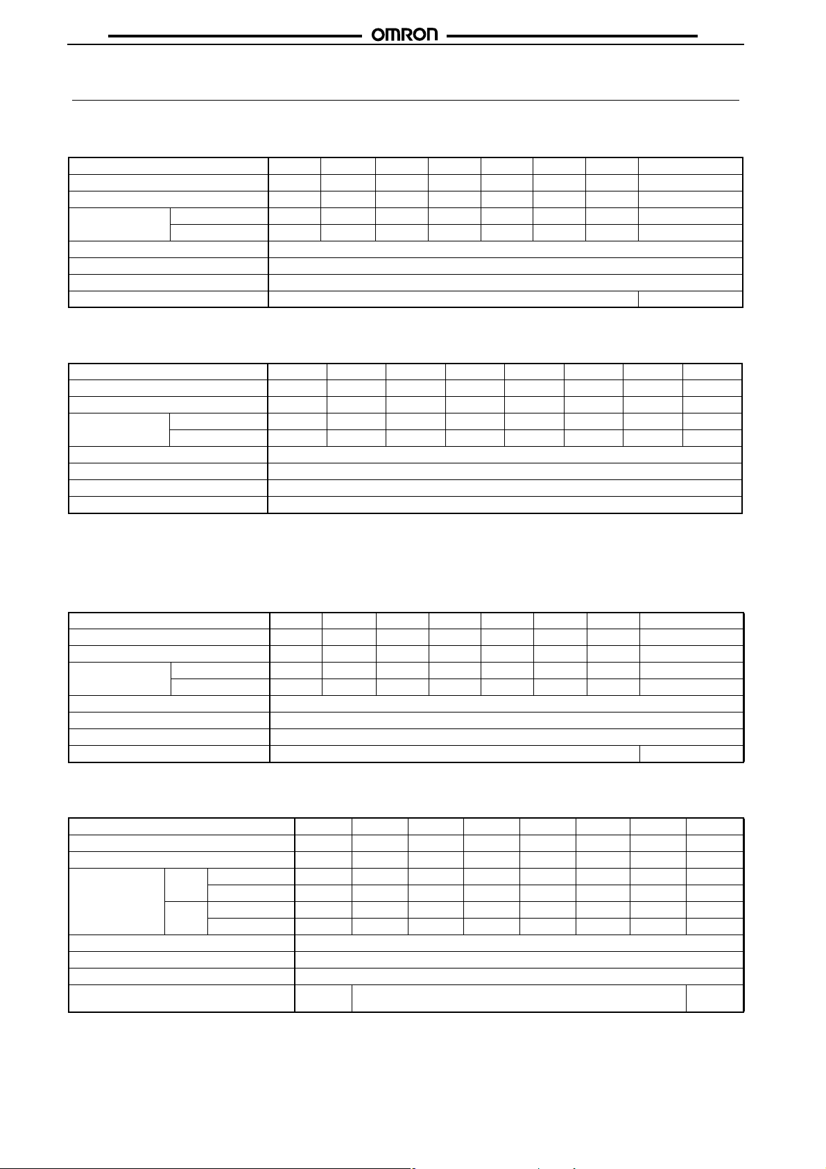
■ Coil Ratings
General-purpose, DPDT Relays
Rated voltage 3 VDC 4.5 VDC 5 VDC 6 VDC 9 VDC 12 VDC 24 VDC 48 VDC
Rated current 66.7 mA 44.6 mA 40 mA 33.3 mA 22.2 mA 16.7 mA 8.3 mA 4.9 mA
Coil resistance 45 Ω 101 Ω 125 Ω 180 Ω 405 Ω 720 Ω 2,880 Ω 9,750 Ω
Coil inductance
(H) (ref. value)
Must operate voltage 70% max. of rated voltage
Must release voltage 10% min. of rated voltage
Max. voltage 200% of rated voltage at 23°C
Power consumption Approx. 200 mW Approx. 235 mW
Low-sensitivity DPDT Relays
Rated voltage 3 VDC 4.5 VDC 5 VDC 6 VDC 9 VDC 12 VDC 24 VDC 48 VDC
Rated current 133.3 mA 88.9 mA 80 mA 66.7 mA 44.3 mA 33.3 mA 16.7 mA 8.3 mA
Coil resistance 22.5 Ω 50.6 Ω 62.5 Ω 90 Ω 203 Ω 360 Ω 1,440 Ω 5,760 Ω
Coil inductance
(H) (ref. value)
Must operate voltage 70% max. of rated voltage
Must release voltage 10% min. of rated voltage
Max. voltage 150% of rated voltage at 23°C
Power consumption Approx. 400 mW
Note: 1. The rated current and coil resistance are measured at a coil temperature of 23°C with a tolerance of ±10%.
2. Operating characteristics are measured at a coil temperature of 23°C.
3. The maximum voltage is the highest voltage that can be imposed on the relay coil.
Armature OFF 0.07 0.16 0.2 0.29 0.63 1.1 4.5 13.7
Armature ON 0.065 0.14 0.18 0.26 0.57 1.06 4.1 12.5
Armature OFF 0.03 0.065 0.08 0.11 0.27 0.52 2.1 7.5
Armature ON 0.02 0.06 0.07 0.1 0.23 0.43 1.8 6.4
G6AG6A
Single-winding Latching, DPDT Relays
Rated voltage 3 VDC 4.5 VDC 5 VDC 6 VDC 9 VDC 12 VDC 24 VDC 48 VDC
Rated current 33.7 mA 22.2 mA 20 mA 16.7 mA 11.1 mA 8.3 mA 4.2 mA 2.5 mA
Coil resistance 89 Ω 202 Ω 250 Ω 360 Ω 810 Ω 1,440 Ω 5,760 Ω 19,000 Ω
Coil inductance
(H) (ref. value)
Must operate voltage 70% max. of rated voltage
Must release voltage 70% max. of rated voltage
Max. voltage 200% of rated voltage at 23°C
Power consumption Approx. 100 mW Approx. 120 mW
Armature OFF 0.15 0.34 0.44 0.64 1.38 2.5 9.2 28.5
Armature ON 0.11 0.25 0.35 0.48 1.07 2 7.2 22
Double-winding Latching, DPDT Relays
Rated voltage 3 VDC 4.5 VDC 5 VDC 6 VDC 9 VDC 12 VDC 24 VDC 48 VDC
Rated current 66.7 mA 40.2 mA 36 mA 30 mA 20 mA 15 mA 7.5 mA 4.2 mA
Coil resistance 45 Ω 112 Ω 139 Ω 200 Ω 450 Ω 800 Ω 3,200 Ω 11,520 Ω
Coil inductance
(H) (ref. value)
Must operate voltage 70% max. of rated voltage
Must release voltage 70% max. of rated voltage
Max. voltage 200% of rated voltage at 23°C
Power consumption Approx.
Note: 1. The rated current and coil resistance are measured at a coil temperature of 23°C with a tolerance of ±10%.
2. Operating characteristics are measured at a coil temperature of 23°C.
3. The maximum voltage is the highest voltage that can be imposed on the relay coil.
Set Armature OFF 0.037 0.09 0.11 0.16 0.38 0.6 2.1 8.5
Armature ON 0.027 0.065 0.08 0.12 0.28 0.45 1.5 6.3
Reset Armature OFF 0.027 0.065 0.08 0.12 0.28 0.45 1.5 6.3
Armature ON 0.037 0.09 0.11 0.16 0.38 0.6 2.1 8.5
200 mW
Approx. 180 mW Approx.
200 mW
110
Page 3
G6AG6A
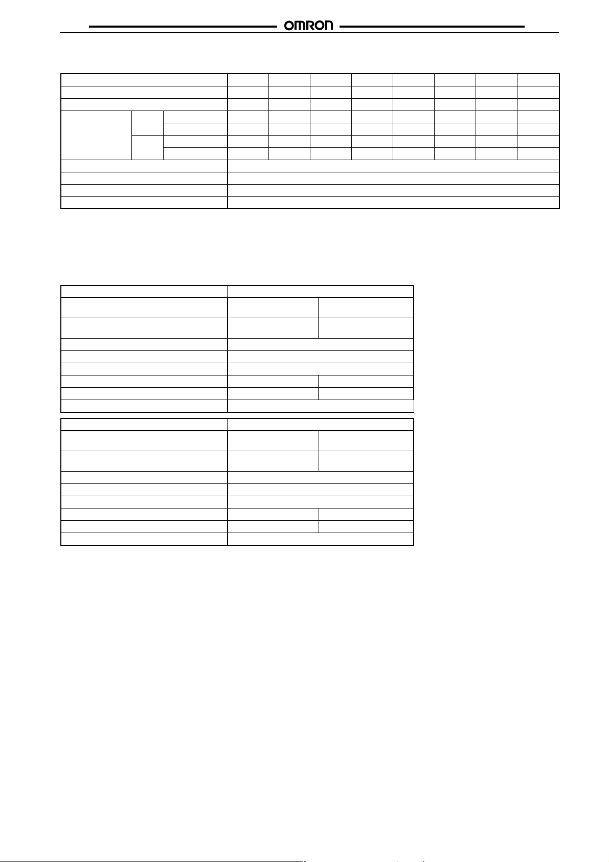
Double-winding Latching, Low-sensitivity DPDT Relays
Rated voltage 3 VDC 4.5 VDC 5 VDC 6 VDC 9 VDC 12 VDC 24 VDC 48 VDC
Rated current 120 mA 79.9 mA 72.5 mA 60 mA 40 mA 30 mA 15 mA 7.5 mA
Coil resistance 25 Ω 56.3 Ω 69 Ω 100 Ω 225 Ω 400 Ω 1,600 Ω 6,400 Ω
Coil inductance
(H) (ref. value)
Must operate voltage 70% max. of rated voltage
Must release voltage 70% max. of rated voltage
Max. voltage 150% of rated voltage at 23°C
Power consumption Approx. 360 mW
Note: 1. The rated current and coil resistance are measured at a coil temperature of 23°C with a tolerance of ±10%.
2. Operating characteristics are measured at a coil temperature of 23°C.
3. The maximum voltage is the highest voltage that can be imposed on the relay coil.
Contact Ratings
■
Load Resistive load
Rated load 0.5 A at 125 VAC;
Contact material Ag (Au-Alloy)
Rated carry current 3 A
Max. switching voltage 250 VAC, 220 VDC
Max. switching current 2 A 1 A
Max. switching power 125 VA, 60 W 62.5 VA, 30 W
Failure rate (reference value) 0.01 mA at 10 mVDC
Set Armature OFF 0.015 0.04 0.05 0.07 0.16 0.28 1.1 4
Armature ON 0.01 0.025 0.035 0.05 0.12 0.2 0.75 2.9
Reset Armature OFF 0.01 0.025 0.035 0.05 0.12 0.2 0.75 2.9
Armature ON 0.015 0.04 0.05 0.07 0.16 0.28 1.1 4
Item G6A-274P-ST(40)-US
(cosφ = 1)
2 A at 30 VDC
Inductive load
(cosφ = 0.4; L/R = 7 ms)
0.3 A at 125 VAC;
1 A at 30 VDC
Item G6AK-274P-ST(40)-US/G6AU-274P-ST-US
Load Resistive load
Rated load 0.5 A at 125 VAC;
Contact material Ag (Au-Alloy)
Rated carry current 3 A
Max. switching voltage 250 VAC, 220 VDC
Max. switching current 2 A 1 A
Max. switching power 125 VA, 60 W 62.5 VA, 30 W
Failure rate (reference value) (See note.) 0.01 mA at 10 mVDC
Note: P level: λ60 = 0.1 x 10⁻⁶/operation
This value was measured at a switching frequency of 60 operations/min and the criterion of contact resistance is 50 Ω. This value
may vary depending on the switching frequency and operating environment. Always double-check relay suitability under actual operating conditions.
(cosφ = 1)
2 A at 30 VDC
Inductive load
(cosφ = 0.4; L/R = 7 ms)
0.25 A at 125 VAC;
1 A at 30 VDC
111
Page 4
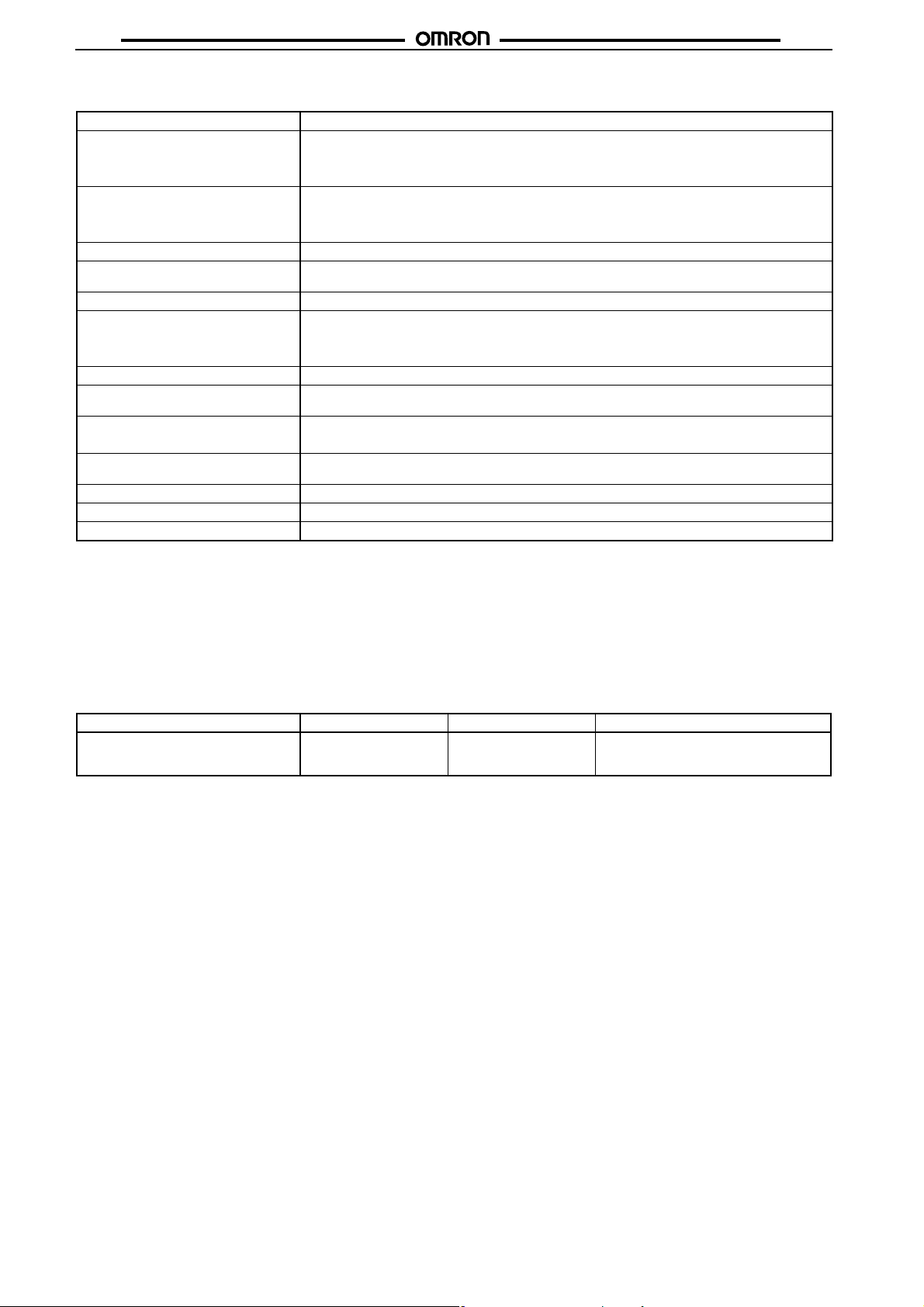
■ Characteristics
Contact resistance (See note 1.) 50 mΩ max.
Operate (set) time (See note 2.) Single-side stable types:
Release (reset) time (See note 2.) Single-side stable types:
Min. set/reset signal width 10 ms min.
Max. operating frequency Mechanical: 36,000 operations/hr
Insulation resistance (See note 3.) 1,000 MΩ min. (at 500 VDC); except for set-reset
Dielectric strength 1,000 VAC, 50/60 Hz for 1 min between coil and contacts
Impulse withstand voltage 1,500 V (10 x 160 µs) (conforms to FCC Part 68)
Vibration resistance Destruction: 10 to 55 to 10 Hz, 2.5-mm single amplitude (5-mm double amplitude)
Shock resistance
Endurance Mechanical: 100,000,000 operations min. (at 36,000 operations/hr)
Ambient temperature Operating: −40°C to 70°C (with no icing)
Ambient humidity Operating: 5% to 85%
Weight Approx. 3.5 g
Note: The data shown above are initial values.
Note: 1. The contact resistance was measured with 10 mA at 1 VDC with a voltage drop method.
2. Values in parentheses are actual values.
3. The insulation resistance was measured with a 500-VDC megohmmeter applied to the same parts as those used for checking
the dielectric strength (except between the set and reset coil).
5 ms max. (approx. 3 ms)
Latching types:
5 ms max. (approx. 2.5 ms)
3 ms max. (approx. 1.2 ms)
Latching types:
5 ms max. (approx. 2.5 ms)
Electrical: 1,800 operations/hr (under rated load)
1,000 VAC, 50/60 Hz for 1 min between contacts of different polarity
1,000 VAC, 50/60 Hz for 1 min between contacts of same polarity
250 VAC, 50/60 Hz for 1 min between set and reset coils
Malfunction: 10 to 55 to 10 Hz, 1.65-mm single amplitude (3.3-mm double amplitude)
2
Destruction: 1,000 m/s
Malfunction: 500 m/s
Electrical: 500,000 operations min. (at 1,800 operations/hr)
(approx. 100G)
2
(approx. 50G)
G6AG6A
Approved Standards
■
UL (File No. E41515)/CSA (File No. LR31928)
Model Contact form Coil ratings Contact ratings
G6A-274P-ST(40)-US
G6AK-274P-ST(40)-US
G6AU-274P-ST-US
DPDT 3 to 48 VDC 0.6 A, 125 VAC
2 A, 30 VDC
0.6 A, 110 VDC
112
Page 5
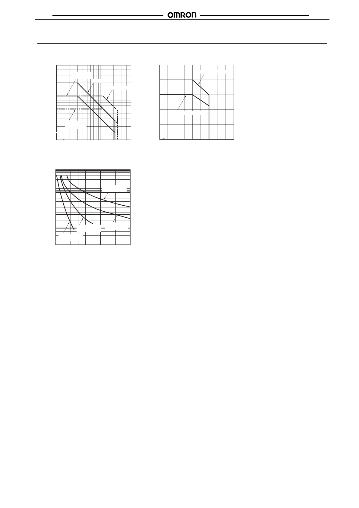
Engineering Data
G6AG6A
Maximum Switching Power Ambient Temperature vs.
Maximum Coil Voltage
5.0
DC inductive
2.0
1.0
0.5
Switching current (A)
0.2
(L/R = 7 ms)
AC inductive
(cosf = 0.4)
0
20 50 100 200 500
Switching voltage (V)
DC resistive
AC resistive
250
200
150
110
100
DPDT: 360, 400 mW
50
DPDT: 100, 180, 200 mW
Maximum coil voltage (%)
0
-40 20 30 40 50 60 70 80 90 100
Ambient temperature (°C)
Endurance
10,000
5,000
3,000
1,000
500
300
4
100
50
30
10
5
3
Endurance (x10 operations)
0 0.2 0.4 0.6 0.8 1.0 1.2 1.4 1.6 1.8 2.0
-274P 125 VAC,
resistive;
-274P 125 VAC,
inductive
Switching current (A)
-274P 30 VDC,
resistive
-274P 30 VDC,
inductive
Note: The maximum coil voltage refers
to the maximum value in a varying
range of operating power voltage,
not a continuous voltage.
113
Page 6
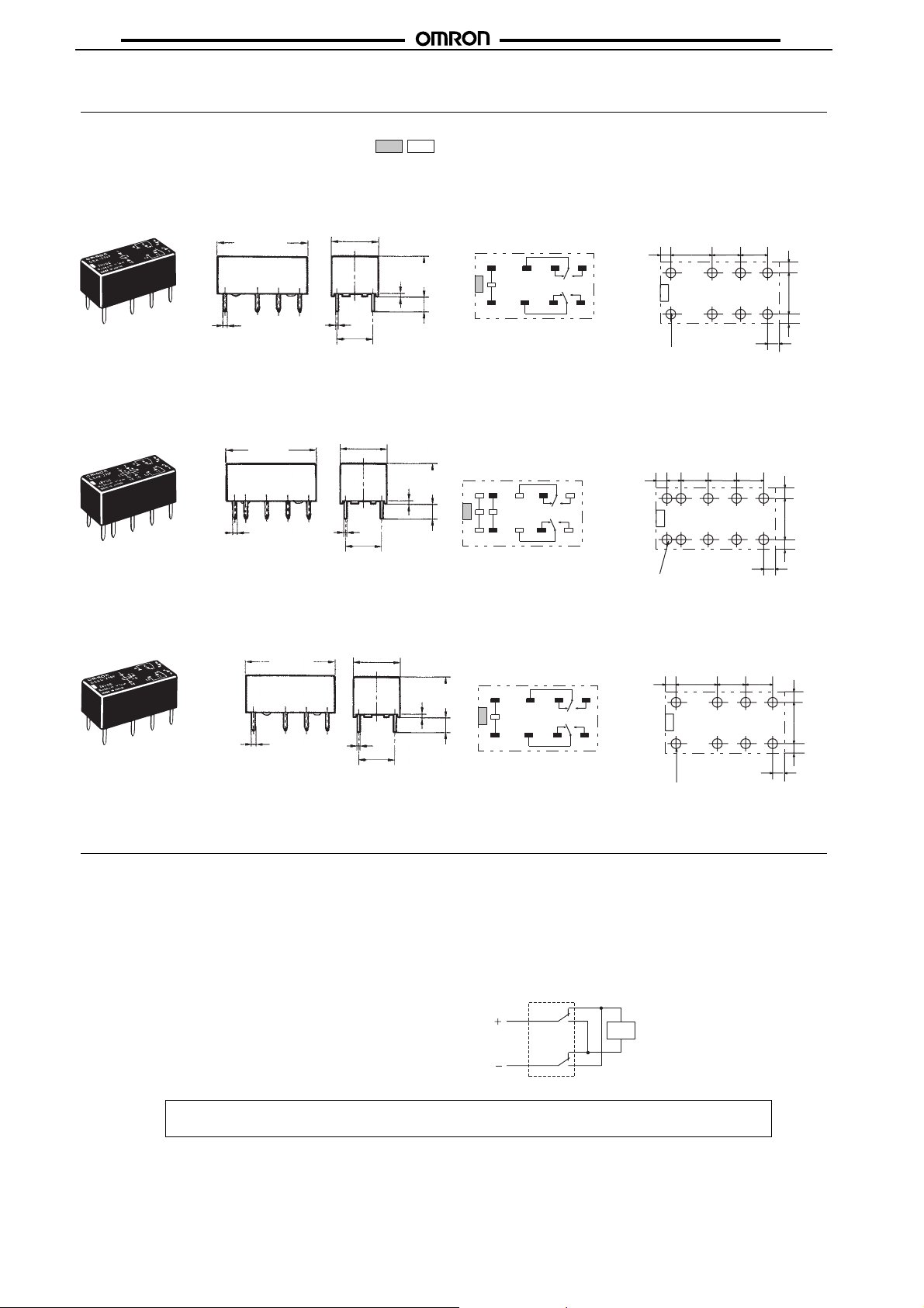
Dimensions
Note: 1. All units are in millimeters unless otherwise indicated.
2. Orientation marks are indicated as follows:
G6AG6A
G6A-274P-ST(40)-US
G6AK-274P-ST(40)-US
G6AU-274P-ST-US
0.6
20.2 max.
(20)*
0.6
20.2 max.
(20)*
20.2 max.
(20)*
0.6
10.1 max.
(9.9)*
0.3
*Average value
0.3
*Average value
0.3
*Average value
7.62
10.1 max.
(9.9)*
7.62
10.1 max.
(9.9)*
7.62
0.64
0.64
8.4 max.
(8.2)*
3.16
8.4 max.
(8.2)*
3.16
0.64
Terminal Arrangement/
Internal Connections
(Bottom View)
1
+
4136
16
-
Terminal Arrangement/
Internal Connections
(Bottom View)
1
+-+
2
6
4
SR
13
11
15
-
16
Terminal Arrangement/
Internal Connections
(Bottom View)
8.4 max.
(8.2)*
3.16
1
+ -
4
S R
13
- +
16
Mounting Holes
(Bottom View)
Tolerance: ±0.1
7.62
(1.2)
8
11
9
Eight, 1.0-dia. holes
Mounting Holes
(Bottom View)
5.08 5.08
(1.2)
7.62
(1.2)
(1.2)
Tolerance: ±0.1
2.54
8
9
(1.2)
Ten, 1-dia. holes
5.08 5.08
5.08
Mounting Holes
(Bottom View)
(1.2)
7.62
(1.2)
(1.2)
Tolerance: ±0.1
8
6
11
9
(1.2)
7.62 5.08 5.08
(1.2)
7.62
(1.2)
(1.2)
Eight, 1.0-dia. holes
Precautions
Long-term Continuously ON Contacts
Using the Relay in a circuit where the Relay will be ON continuously for long periods (without switching) can lead to unstable
contacts because the heat generated by the coil itself will affect
the insulation, causing a film to develop on the contact surfaces.
We recommend using a latching relay (magnetic-holding relay) in
this kind of circuit. If a single-side stable model must be used in
this kind of circuit, we recommend using a fail-safe circuit design
that provides protection against contact failure or coil burnout.
Relay Handling
When washing the product after soldering the Relay to a PCB,
use a water-based solvent or alcohol-based solvent, and keep the
solvent temperature to less than 40°C. Do not put the Relay in a
cold cleaning bath immediately after soldering.
ALL DIMENSIONS SHOWN ARE IN MILLIMETERS.
To convert millimeters into inches, multiply by 0.03937. To convert grams into ounces, multiply by 0.03527.
Cat. No. K020-E1-09
114
Double-swicthing load in two poles
Double-switching in two poles as shown in the figure below, one
pole and two pole interval may become MBB(Make Before
Break) mechanically according to the timing of the point of contact switching (By the short-circuit mode), and the malfunction
might be caused.
In such a circuit, direct electric switching should be avoided, and
concern for contact to be carried after the contact of Relay absolutely switches in condition of no load.
Contacts
Load
 Loading...