

Page 1
AC SERVOMOTORS/SERVO DRIVES
G5-series
Pulse-train Input Type
User’s Manual
R88D-KE(AC Servomotors)
R88M-KP(AC Servo Drives)
I584-E1-02
Page 2
15171
To: All Customers
Corrections Insert
OMRON Corporation Cat. No. I584-E1-02
Thank you for supporting OMRON and OMRON products.
Some mistakes were discovered in the manual listed below. We sincerely apologize for these mistakes.
Please mark your manual so that the corrections are noted on the pages concerned, and then securely add
any required pages from this Notification to the rear of the manual.
Applicable Manuals
This Notification applies to the following manuals: AC SERVOMOTORS/SERVO DRIVES G5-series Pulse-tr1in
Input Type USER'S MANUAL (Cat.I584-E1-02).
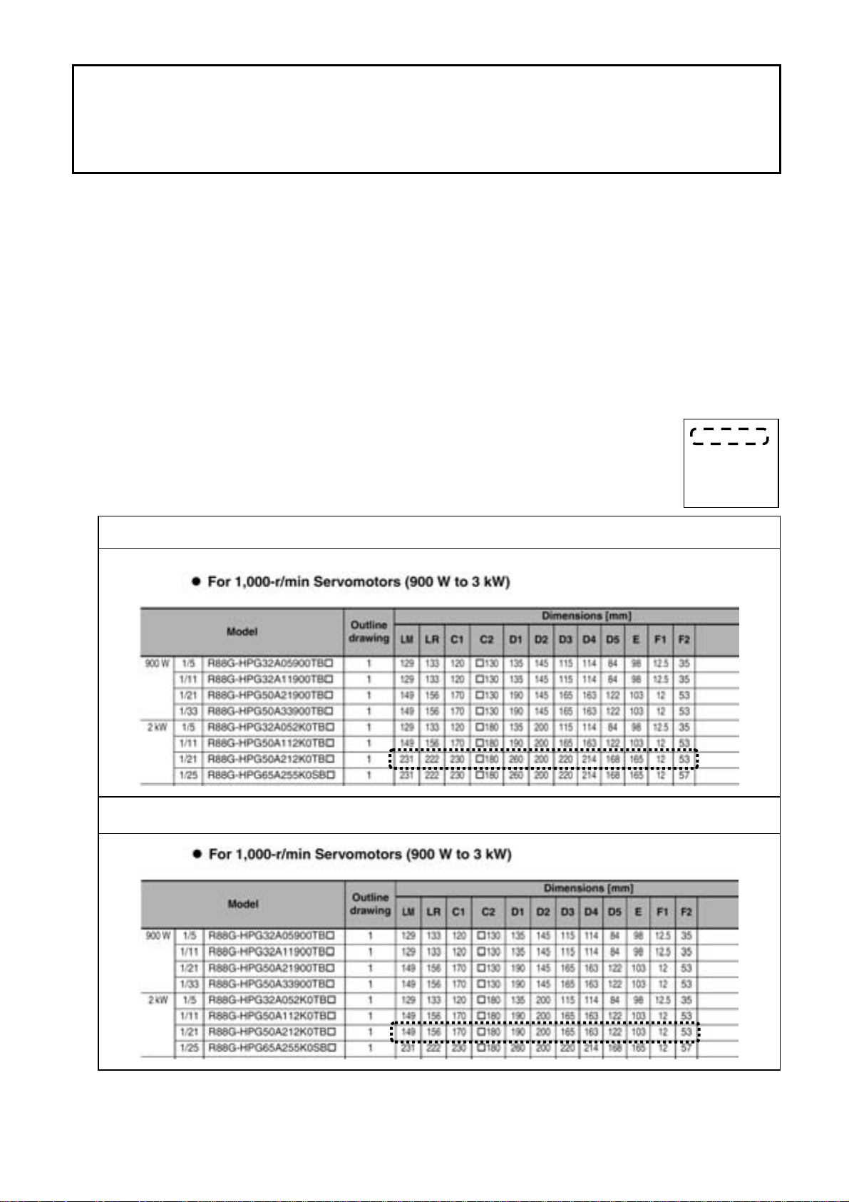
Relevant Location: Decelerator Dimensions
1 Page 2-52
For 1,000-r/min Servomotors (900 W to 3 kW)
The frames show
the locations of
the additions and
changes.
Current Contents
Corrected Contents
Page 3
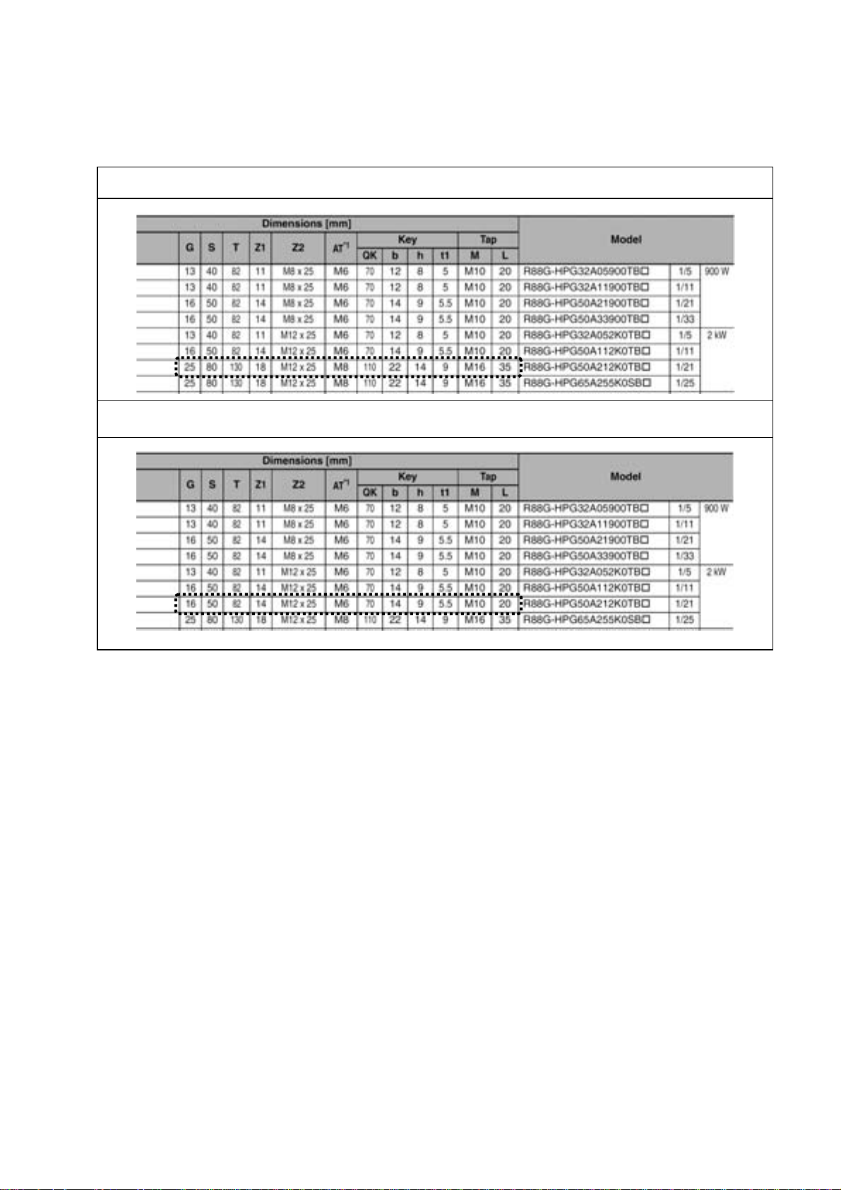
2 Page 2-53
For 1,000-r/min Servomotors (900 W to 3 kW)
Current Contents
Corrected Contents
Page 4

OMRON, 2012
All rights reserved. No part of this publication may be reproduced, stored in a retrieval system, or transmitted, in any
form, or by any means, mechanical, electronic, photocopying, recording, or otherwise, without the prior written permission of OMRON.
No patent liability is assumed with respect to the use of the information contained herein. Moreover, because OMRON is
constantly striving to improve its high-quality products, the information contained in this manual is subject to change
without notice. Every precaution has been taken in the preparation of this manual. Nevertheless, OMRON assumes no
responsibility for errors or omissions. Neither is any liability assumed for damages resulting from the use of the information contained in this publication.
Page 5

Introduction
Thank you for purchasing an OMNUC G5-series Servo Drive (Pulse-train Input Type). This User’s
Manual describes the installation and wiring methods of the OMNUC G5-series Servo Drives (Pulsetrain Input Type) and parameter setting method which is required for the operation, as well as
troubleshooting and inspection methods.
Intended Audience
This User’s Man ua l is in te nded for the following personnel, who must also have knowledge of electrical
systems (an electrical engineer or the equivalent).
• Personnel in charge of introducing the FA equipment
• Personnel in charge of designing the FA systems
• Personnel in charge of managing the FA systems and facilities
Introduction
Notice
This User’ s Manual contains information you need to know to correctly use the OMNUC G5-series
Servo Drives (Pulse-train Inpu t Type) and peripheral equipment.
Before using the Servo Drive, read this User’s Manual and gain a full understanding of the information
provided herein.
After you finished reading this User’s Manual, keep it in a convenient place so that it can be referenced
at any time.
Make sure this User’s Manual is delivered to the end user.
OMNUC G5-series (Pulse-train Input Type) AC Servomotors and Servo Drives User’s Manual
1
Page 6
Read and Understand this Manual
Read and Understand this Manual
Warranty and Limitations of Liability
WARRANTY
OMRON’s exclusive warranty is that the products are free from defects in materials and workmanship for a period of
one year (or other period if specified) from date of sale by OMRON.
OMRON MAKES NO WA RRANTY OR REPRESENTATION, EXPRESS OR IMPLIED, REGARDING
NONINFRINGEMENT, MERCHANTABILITY, OR FITNESS FOR PARTICULAR PURPOSE OF THE PRODUCTS.
ANY BUYER OR USER ACKNOWLEDGES THAT THE BUYER OR USER ALONE HAS DETERMINED THAT THE
PRODUCTS WILL SUITABLY MEET THE REQUIREMENTS OF THEIR INTENDED USE. OMRON DISCLAIMS ALL
OTHER WARRANTIES, EXPRESS OR IMPLIED.
LIMITATIONS OF LIABILITY
OMRON SHALL NOT BE RESPONSIBLE FOR SPECIAL, INDIRECT, OR CONSEQUENTIAL DAMAGES, LOSS OF
PROFITS OR COMMERCIAL LOSS IN ANY WAY CONNECTED WITH THE PRODUCTS, WHETHER SUCH
CLAIM IS BASED ON CONTRACT, WARRANTY, NEGLIGENCE, OR STRICT LIABILITY.
In no event shall the responsibility of OMRON for any act exceed the individual price of the product on which liability
is asserted.
IN NO EVENT SHALL OMRON BE RESPONSIBLE FOR WARRANTY, REPAIR, OR O THER CLAIMS REGA RDING
THE PRODUCTS UNLESS OMRON’S ANALYSIS CONFIRMS THAT THE PRODUCTS WERE PROPERLY
HANDLED, STORED, INSTALLED, AND MAINTAINED AND NOT SUBJECT TO CONTAMINATION, ABUSE,
MISUSE, OR INAPPROPRIATE MODIFICATION OR REP A IR.
2
OMNUC G5-series (Pulse-train Input Type) AC Servomotors and Servo Drives User’s Manual
Page 7

Read and Understand this Manual
Application Considerations
SUITABILITY FOR USE
OMRON shall not be responsible for conformity with any standards, codes, or regulations that apply to the
combination of products in the customer’s application or use of the products.
At the customer’s request, OMRON will provide applicable third party certification documents identifying ratings and
limitations of use that apply to the products. This information by itself is not sufficient for a complete determination of
the suitability of the products in combination with the end product, machine, system, or other application or use.
The following are some examples of applications for which particular attention must be given. This is not intended to
be an exhaustive list of all possible uses of the products, nor is it intended to imply that the uses listed may be
suitable for the products:
• Outdoor use, uses involving potential chemical contamination or electrical interference, or conditions or uses not
described in this manual.
• Nuclear energy control systems, combustion systems, railroad systems, aviation systems, medical equipment,
amusement machines, vehicles, safety equipment, and installations subject to separate indu stry or government
regulations.
• Systems, machines, and equipment that could present a risk to life or property. Please know and observe all
prohibitions of use applicable to the products.
NEVER USE THE PRODUCTS FOR AN APPLICATION INVOLVING SERIOUS RISK TO LIFE OR PROPERTY
WITHOUT ENSURING THAT THE SYSTEM AS A WHOLE HAS BEEN DESIGNED TO ADDRESS THE RISKS,
AND THAT THE OMRON PRODUCTS ARE PROPERLY RATED AND INSTALLED FOR THE INTENDED USE
WITHIN THE OVERALL EQUIPMENT OR SYSTEM.
PROGRAMMABLE PRODUCTS
OMRON shall not be responsible for the user’s programming of a programmable product, or any consequence
thereof.
OMNUC G5-series (Pulse-train Input Type) AC Servomotors and Servo Drives User’s Manual
3
Page 8
Read and Understand this Manual
Disclaimers
CHANGE IN SPECIFICATIONS
Product specifications and accessories may be changed at any time based on improvements and other reasons. It is
our practice to change model numbers when published ratings or features are changed, or when significant
construction changes are made. However, some specifications of the products may be changed without any notice.
When in doubt, special model numbers may be assigned to fix or establish key specifications for your application on
your request. Please consult with your OMRON representative at any time to confirm actual specifications of
purchased products.
DIMENSIONS AND WEIGHTS
Dimensions and weights are nominal and are not to be used for manufacturing purposes, even when tolerances are
shown.
PERFORMANCE DATA
Performance data given in this manual is provided as a guide for the user in determining suitability and does not
constitute a warranty . It ma y represent the result of OMR ON’ s test conditions , and the users m ust correlate it to actual
application requirements. Actual performance is subject to the OMRON Warranty and Limitations of Liability.
ERRORS AND OMISSIONS
The information in this manual has been carefully checked and is believed to be accurate; however, no responsibility
is assumed for clerical, typographical, or proofreading errors, or omissions.
4
OMNUC G5-series (Pulse-train Input Type) AC Servomotors and Servo Drives User’s Manual
Page 9
Safety Precautions
To ensure that the OMNUC G5-series (Pulse-train Input Type) Servomotor/Servo Drive as well as
peripheral equipment are used safely an d correctly, be sure to read this Safe ty Precaution s section and
the main text before using the product. Learn all items you should know before use, regarding the
equipment as well as the required safety information and precautions.
Make an arrangement so that this User’s Manual also gets to the end user of this product.
After reading this User’s Manual, keep it in a convenient place so that it can be referenced at any time.
Explanation of Displays
The precautions explained in this section describe important information regarding safety and must
be followed without fail.
The displays of precautions in this User’s Manual and their meanings are explained belo w.
Safety Precautions
DANGER
Caution
Even those items denoted by the caution symbol may lead to a serious outcome depending on the
situation. Accordingly, be sure to observe all safety precautions.
Precautions for Safe Use
Precautions on what to do and what not to do to ensure safe usage of the product.
Precautions for Correct UsePrecautions for Correct Use
Precautions on what to do and what not to do to ensure proper operation and performance.
Additional Information
This information is provided to increase understanding or make operation easier.
Explanation of Symbols
Indicates a potentially hazardous situation which, if not avoided, could result in
death or serious injury. Additionally, there may be severe property damage.
Indicates a potentially hazardous situation which, if not avoided, may result in
minor or moderate injury, or property damage.
∆ This symbol indicates danger and caution.
The specific instruction is indicated using an illustration or text inside or near ∆.
The symbol shown to the left indicates “beware of electric shock.”
This symbol indicates a prohibited item (an item you must not do).
The specific instruction is indicated using an illustration or text inside or near .
The symbol shown to the left indicates “disassembly prohibited.”
This symbol indicates a compulsory item (an item that must be done).
The specific instruction is indicated using an illustration or text inside or near .
The symbol shown to the left indicates “grounding required.”
OMNUC G5-series (Pulse-train Input Type) AC Servomotors and Servo Drives User’s Manual
5
Page 10
Safety Precautions
Precautions for Safe Use of This Product
Illustrations contained in this User’s Manual sometimes depict conditions without covers and safety
shields for the purpose of showing th e details. When using this product, be sure to install the covers
and shields as specified and use the product according to this User’s Manual.
If the product has been stored for an extended period of time, contact your OMRON sales
representative.
DANGER
Be sure to ground the frame ground terminals for the Servo Drive and Servomotor with 100 VAC or
200 VAC to 100 Ω or less, and for the Servo Drive and Servomotor with 400 VAC to 10 Ω or less.
Electric shock may result.
Never put you hand inside the Servo Drive.
Electric shock may result.
While the power is supplied, do not remove the front cover, terminal covers, cables, and options.
Electric shock may result.
Operation, maintenance or inspection by unauthorized personnel is prohibited.
Electric shock or injury may result.
Before carrying out wiring or inspection, turn OFF the main circuit power and wait for at least 15 minutes.
Electric shock may result.
Do not damage, pull, stress strongly, pinch the cables or place heavy articles on them.
Electric shock, malfunction, or burn damage may result.
Never enter the operating area during operation.
Injury may result.
Never modify the Servo Drive.
Injury or equipment damage may result.
Install a stopping device on the machine to ensure safety.
* The holding brake is not a stopping device to ensure safety.
Injury may result.
Install an immediate stop device externally to the machine so that the operation can be stopped and the
power supply cut off immediately.
Injury may result.
When the power is restored after a momentary power interruption, the machine may restart suddenly.
Never come close to the machine when restoring power.
* Implement measures to ensure safety of people nearby even when the machine is restarted.
Injury may result.
After an earthquake, be sure to conduct safety checks.
Electric shock, injury, or fire may result.
Never drive the Servomotor using an external drive source.
Fire may result.
6
OMNUC G5-series (Pulse-train Input Type) AC Servomotors and Servo Drives User’s Manual
Page 11
Safety Precautions
DANGER
Do not place flammable materials near the Servomotor, Servo Drive, or Regeneration Resistor.
Fire may result.
Install the Servomotor, Servo Drive, and Regeneration Resistor on non-flammable materials such as
metals.
Fire may result.
Do not use the Servomotor with cables submerged in oil or water.
Electric shock, injury, or fire may result.
Never connect a power supply directly to the Servomotor.
Fire or failure may result.
Do not perform wiring or any operation with wet hands.
Electric shock, injury, or fire may result.
Do not touch the key grooves with bare hands if a Servomotor with shaft-end key grooves is being used.
Injury may result.
Install the Servomotor and Servo Drive before wiring them.
Electric shock may result.
The Servo Drive radiator, Regeneration Resistor, Servomotor, etc., may become hot
while the power is supplied or remain hot for a while even after the power supply is cut off. Never touch
these components.
Burn injury may result.
Use the Servomotor and Servo Drive in a specified combination.
Fire or equipment damage may result.
Caution
Do not store or install the Servo Drive in the following locations:
• Location subject to direct sunlight
• Location where the ambient temperature exceeds the specified level
• Location where the relative humidity exceeds the specified level
• Location subject to condensation due to rapid temperature changes
• Location subject to corrosive or flammable gases
• Location subject to high levels of dust, salt content, or iron dust
• Location subject to splashes of water, oil, chemicals, etc.
• Location where the Servo Drive may receive vibration or impact directly
Electric shock, fire, or equipment damage may result.
OMNUC G5-series (Pulse-train Input Type) AC Servomotors and Servo Drives User’s Manual
7
Page 12
Safety Precautions
Storage and Transportation
When transporting the Servo Drive, do not hold it by the cables or Servomotor shaft.
Injury or failure may result.
Do not overload the Servo Drive or Servomotor. (Follow the instructions on the product label.)
Injury or failure may result.
Use the Servomotor eye-bolts only when transporting the Servomotor.
Do not use them to transport the machine.
Injury or failure may result.
Caution
8
OMNUC G5-series (Pulse-train Input Type) AC Servomotors and Servo Drives User’s Manual
Page 13
Installation and Wiring
Do not step on the Servo Drive or place heavy articles on it.
Injury may result.
Do not block the intake or exhaust openings.
Do not allow foreign objects to enter the Servo Drive.
Fire may result.
Be sure to observe the mounting direction.
Failure may result.
Provide the specified clearance between the Servo Drive and the inner surface of the control panel or other
equipment.
Fire or failure may result.
Safety Precautions
Caution
Do not apply strong impact on the Servo Drive.
Failure may result.
Wire the cables correctly and securely.
Runaway Servomotor, injury, or failure may result.
Tighten the Servo Drive mounting screws, terminal block screws , and cable screws to the specified torque.
Failure may result.
Use crimp terminals to wire screw type terminal blocks. Do not connect bare stranded wires directly to
terminals blocks.
Fire may result.
Only use the power supply voltage specified in this User’s Manual.
Burn damage may result.
In locations where the power supply infrastructure is poor, make sure the rated voltage can be supplied.
Failure may result.
Provide safety measures, such as a breaker, to protect against short circuiting of external wiring.
Fire may result.
If the Servo Drive is used in the following locations, provide sufficient shielding measures.
• Location subject to static electricity or other forms of noise
• Location subject to a strong electric or magnetic field
• Location where exposure to radioactivity may occur
• Location near power supply lines
Failure may result.
Connect an immediate stop relay in series with the brake control relay.
Injury or failure may result.
When connecting the battery, make sure the polarity is correct.
Battery damage or explosion may result.
OMNUC G5-series (Pulse-train Input Type) AC Servomotors and Servo Drives User’s Manual
9
Page 14
Safety Precautions
Operation and Adjustment
Conduct a test operation after confirming that the equipment is not affected.
Equipment damage may result.
Before operating the Servo Drive in an actual environment, check if it operates correctly based on the
parameters you have set.
Equipment damage may result.
Never adjust or set parameters to extreme values, because it will make the operation unstable.
Injury may result.
Separate the Servomotor from the mechanical system and check its operation before installing the
Servomotor to the machine.
Injury may result.
Caution
If an error (alarm) occurs, remove the cause and ensure safety, and then reset the error (alarm) and restart
the operation.
Injury may result.
Do not use the built-in brake of the Servomotor for normal braking operation.
Failure may result.
Do not operate the Servomotor connected to an excessive load inertia.
Failure may result.
Install protective and safety devices to prevent idling or locking of the electromagnetic brake or the gear
head, or leakage of grease from the gear head.
Injury, damage, or taint damage result.
If the Servo Drive fails, cut off the power supply to the Servo Drive at the power supply.
Fire may result.
Do not turn ON and OFF the main Servo Drive power supply frequently.
Failure may result.
Do not apply strong impact on the Servomotor shaft or Servo Drive.
Failure may result.
10
The Servomotor may not be able to keep a stopped state without control.
Install an appropriate stopping device to ensure safety.
Equipment damage or injury may result.
OMNUC G5-series (Pulse-train Input Type) AC Servomotors and Servo Drives User’s Manual
Page 15

Maintenance and Inspection
After replacing the Servo Drive, transfer to the new Servo Drive all data needed to resume operation,
before restarting operation.
Equipment damage may result.
Never repair the Servo Drive by disassembling it.
Electric shock or injury may result.
Be sure to turn OFF the power supply when the Servo Drive is not going to be used for a prolonged period
of time.
Injury or malfunction may result.
Safety Precautions
Caution
OMNUC G5-series (Pulse-train Input Type) AC Servomotors and Servo Drives User’s Manual
11
Page 16
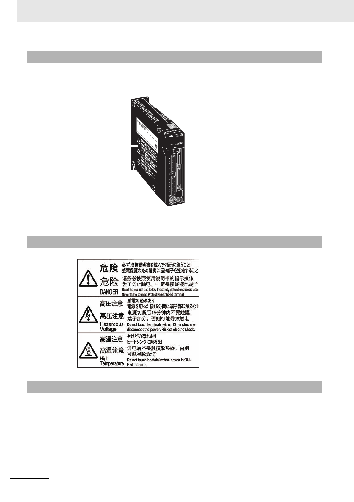
Safety Precautions
Location of W arning Label
The Servo Drive bears a warning label at the following location to provide handling warnings.
When handling the Servo Drive, be sure to observe the instructions provided on this label.
VOLTAGE
PHASE
F L C
FREQ
POWER
SERIAL No.
OMRON Corporation
INPUT OUTPUT
100~115V
1Ø 3Ø
2.2A
50/60Hz
T09020002
45 1V
1.7A
0~500Hz
100W
Location of Warning
Label
(R88D-KP01H)
Instructions on Warning Label
MADE IN JAPAN
Disposal
12
• When disposing of the battery, insulate it using tape, and dispose of it by following the applicable
ordinances of your local government.
• Dispose of the Servo Drive as industrial waste.
OMNUC G5-series (Pulse-train Input Type) AC Servomotors and Servo Drives User’s Manual
Page 17
Items to Check After Unpacking
Items to Check After Unpacking
After unpacking, check the following items.
• Is this the model you ordered?
• Was there any dama ge sustained during shipment?
Accessories
Safety Precautions document × 1 copy
• Connectors, mounting screws, mounting brackets, and other accessories other than those in the
table below are not supplied. They must be prepared by the customer.
• If any item is missing or a problem is found such as Servo Drive damage, contact the OMRON dealer
or sales office where you purchased your product.
Connector for
Connector for External
Regeneration Resistor
connection terminals
and Motor connection
terminals
Included
–
Specifications
Single-phase/
3-phase 200 VAC
3-phase 200 VAC 2 kW
100 W
200 W
400 W
750 W
1 kW
1.5 kW
5 kW
main circuit
power supply
terminals and
control circuit
power supply
terminals
Safety
connector
Included
Mounting
brackets
–
Included3 kW
OMNUC G5-series (Pulse-train Input Type) AC Servomotors and Servo Drives User’s Manual
13
Page 18
Revision History
Revision History
The manual revision code is a number appended to the end of the catalog number found in the bottom
right-hand corner of the front and back covers.
Example
Cat.No.
Revision
Code
01 April 2012 Original production
02 August 2012 Front cover: Corrected model n u mb e r s.
Revision Date Revised Content
I584-E1-02
Pages 2-16 and 2-17: Corrected specifications and deleted rows in
middle table.
Page 3-63: Deleted rows from middle two tables.
Pages 3-69, 3-73, 3-76, and 3-79: Corrected specifications in
parentheses before table.
Pages 3-70, 3-74, 3-77, and 3-80: Deleted page.
Page 4-6: Corrected bolt sizes and removed columns from middle
table.
Revision code
14
OMNUC G5-series (Pulse-train Input Type) AC Servomotors and Servo Drives User’s Manual
Page 19
Manual Configuration
This User’s Manual consists of the following sections.
Read the necessary section or sections referring the following table.
Section 1 Features and
System
Configuration
Section 2 Models and
External
Dimensions
Section 3 Specifications This section provides the general specifications, characteristics,
Section 4 System Design This section explains the installation conditions, wiring methods which
Section 5 Basic Control
Mode
Section 6 Applied
Functions
Section 7 Parameter
Details
Section 8 Operation This section gives the operational procedure and explains how to
Section 9 Adjustment
Functions
Section 10
Appendices
Troubleshooting
and
Maintenance
This section explains the features of the Servo Drive, name of each
part, and applicable EC Directives and UL standards.
This section explains the models of Servo Drives, Servomotors,
Decelerators, and peripheral devices, and provides the external
dimensions and mounting dimensions.
connector specifications, and I/O circuits of the Servo Drives as well as
the general specifications, characteristics, encoder specifications of the
Servomotors and other peripheral devices.
include wiring conforming to EMC directives, and regenerative energy
calculation methods for the Servo Drives, Servomotors, and
Decelerators. It also explains the perf ormance of External Regeneration
Resistors.
This section provides the outline of functions and settings for each
control mode.
This section provides the outline and settings of the applied functions
such as damping control, electronic gear, gain switching, and
disturbance observer.
This section explains the set value and setting details of each
parameter.
operate in each mode.
This section explains the functions, setting methods, and items to note
regarding various gain adjustments.
This section explains the items that must be checked when problems
occur, error diagnosis using the alarm display and measures, error
diagnosis based on the operating condition and measures, and periodic
maintenance.
The appendices provide connection examples with OMRON’s PLC and
Position Controller, as well as lists of parameters.
Manual Configuration
Outline
OMNUC G5-series (Pulse-train Input Type) AC Servomotors and Servo Drives User’s Manual
15
Page 20
Manual Structure
Manual Structure
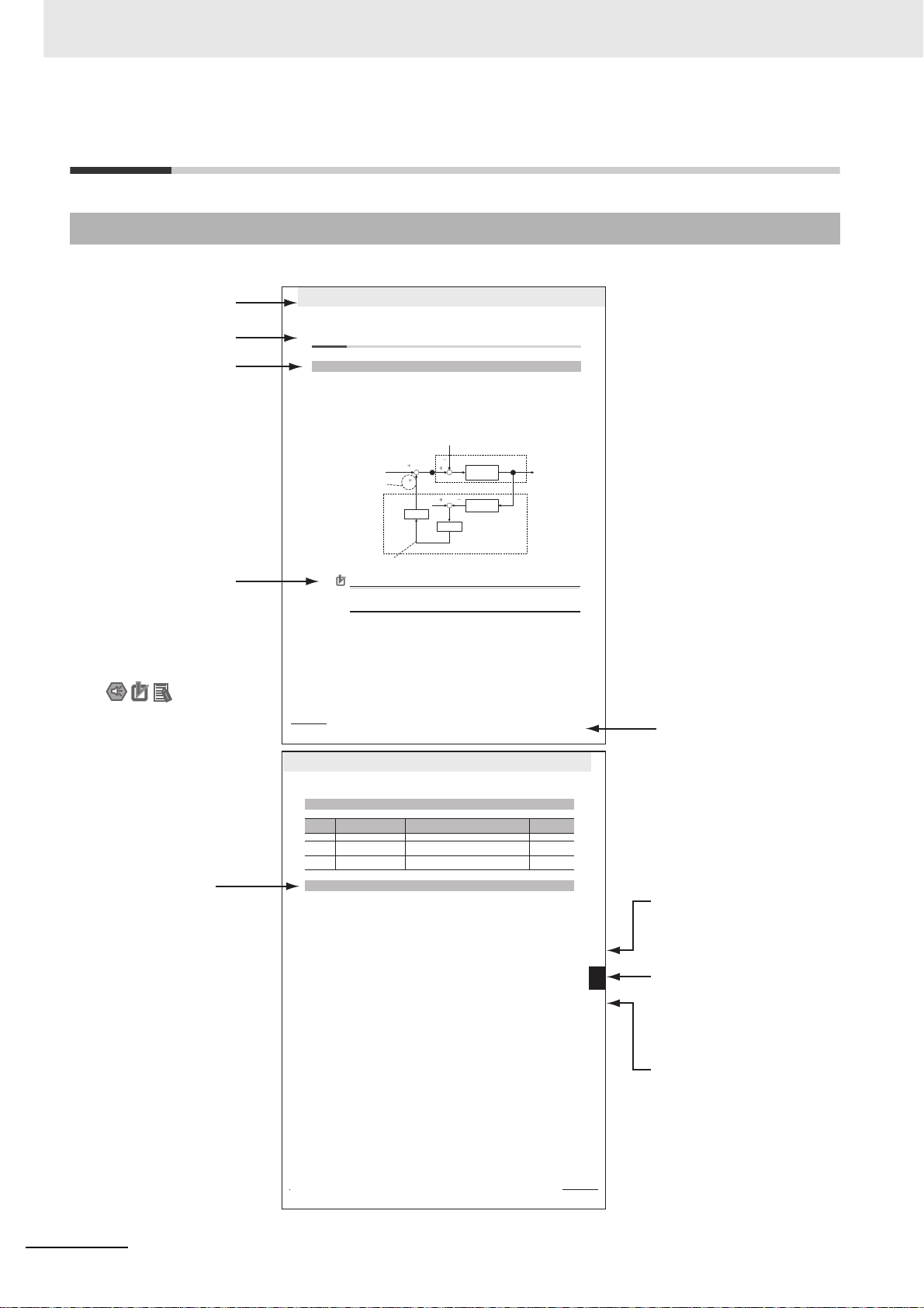
Page Structure and Symbol Icons
The following page structure and symbol icons are used in this User’s Manual.
Level 1 heading
Level 2 heading
Level 3 heading
Note, Supplementary
Information,
Reference Target
A note, supplementary
information, reference
target, etc. are provided
with difference icons.
6 Applied Functions
6-11 Disturbance Observer Function
6-11-1 Outline of the Function
The disturbance observer function enables you to lower the effect of the disturbance torque and reduce
vibration by using the estimated disturbance torque value.
You can use the disturbance observer for position control or speed control in the following situations.
• The servo is ON.
• The Servomotor can rotate normally without any failures.
• The realtime autotuning function is disabled.
• The instantaneous speed observer function is disabled.
Torque command
Add to the direction
that negates
the disturbance
Disturbance torque estimation value
Precautions for Correct UsePrecautions for Correct Use
If there is a resonance point below the cut-off frequency estimated by the disturbance observer,
or if the disturbance torque contains a large amount of high-frequency content, the disturbance
observer may not produce the expected results.
6 - 41
Setting with
Pn623
OMNUC G5-series (Pulse-train Input Type) AC Servomotors and Servo Drives User’s Manual
Gain
Disturbance torque
Setting with Pn624
Filter
Motor+load
Load model
Disturbance observer
Motor SpeedTorque command
Manual Name
Operation Steps
Describes the
operation steps.
6 Applied Functions
6-11-2 Parameters Requiring Settings
Parameter
Pn610 Function Expansion Setting Set the bits related to the disturbance observer. P.7-56
Pn623 Disturbance Torque
Pn624 Disturbance Observer Filter
6-11-3 Operating Procedure
OMNUC G5-series (Pulse-train Input Type) AC Servomotors and Servo Drives User’s Manual
Name Description Reference
No.
Compensation Gain
Setting
1
Set Function Expansion Setting (Pn610).
Set whether to enable or disable the disturbance observer in bit 1.
0: Disabled
1: Enabled
Set the operating conditions for enabling the function in bit 2.
0: Enabled at all time
1: Enabled only when Gain 1 is selected
2
Set Disturbance Observer Filter Setting (Pn624).
Set a small value in Disturbance Torque Compensation Gain (Pn623). Change t he value in
Disturbance Observer Filter Setting (Pn624) from a large value to a smaller one to
determine a setting that provides a balance between the effect of suppressing the
influence of disturbance and the operating noise level.
3
Set Disturbance Torque Compensation Gain (Pn623).
Change the value of Disturbance Torque Compensation Gain (Pn623) from a small value
to a larger value to determine a setting that provides a balance between the effect of
suppressing the influence of disturbance and the operating noise level.
Set the compensation gain for the disturbance torque. P.7-58
Set the filter time constant for disturbance torque
compensation.
P.7 - 5 8
6 - 42
Level 2 heading
Shows which sub-section
the content of the current
noitcnuF revresbO ecnabrutsiD 11-6
6
1-6
1
Outline of the Function 1-
page belongs to.
Section Number of
Level 1 heading
Shows which section the
content of the current
page belongs to.
Level 3 heading
Shows which paragraph
the content of the current
page belongs to.
16
Note The above page is only a sample f or illustrative purposes. It is not the actual content of this User’s Manual.
OMNUC G5-series (Pulse-train Input Type) AC Servomotors and Servo Drives User’s Manual
Page 21
Special Information
Special information in this manual is classified as follows:
Precautions for Safe Use
Precautions on what to do and what not to do to ensure safe usage of the product.
Precautions for Correct UsePrecautions for Correct Use
Precautions on what to do and what not to do to ensure proper operation and performance.
Additional Information
Additional information to read as required.
This information is provided to increase understanding or make operation easier.
Manual Structure
OMNUC G5-series (Pulse-train Input Type) AC Servomotors and Servo Drives User’s Manual
17
Page 22

Manual Structure
18
OMNUC G5-series (Pulse-train Input Type) AC Servomotors and Servo Drives User’s Manual
Page 23
Sections in this Manual
Sections in this Manual
Features and System
1
2A
3
4A
5
Configuration
Models and External
Dimensions
Specifications
System Design
Basic Control Mode
10
Troubleshooting
and Maintenance
Appendices
1
2A
10
3
4
5
6
7
6
7
8
9
8
Applied Functions
9
Parameter Details
Operation
Adjustment Functions
OMNUC G5-series (Pulse-train Input Type) AC Servomotors and Servo Drives User’s Manual
19
Page 24

CONTENTS
CONTENTS
Introduction ...............................................................................................................1
Read and Understand this Manual ..........................................................................2
Safety Precautions....................................................................................................5
Items to Check After Unpacking............................................................................13
Revision History......................................................................................................14
Manual Configuration .............................................................................................15
Manual Structure.....................................................................................................16
Sections in this Manual ..........................................................................................19
CONTENTS ..............................................................................................................20
Section 1 Features and System Configuration
1-1 Outline...................................................................................................................................... 1-2
1-1-1 Outline of OMNUC G5-series Servo Drives (Pulse-train Input Type)..........................................1-2
1-1-2 Features of OMNUC G5-series Servo Drives (Pulse-train Input Type).......................................1-2
1-2 System Configuration................. ... ... ... ... ....................................... ... .... ... ............................... 1-3
1-3 Names and Functions............................................................................................................. 1-4
1-3-1 Servo Drive Part Names.............................................................................................................1-4
1-3-2 Servo Drive Functions.................................................................................................................1-5
1-4 System Block Diagram...................... ... ... .... ...................................... .... ... ... ............................ 1-6
1-5 Applicable Standards............................................................................................................1-10
1-5-1 EC Directives............................................................................................................................1-10
1-5-2 UL and cUL Standards..............................................................................................................1-10
1-5-3 SEMI F47............................................................................................. ... ..................................1-10
Section 2 Models and External Dimensions
2-1 Servo System Configuration ............................................ .... ... ... ....................................... ... .. 2-2
2-2 How to Read Model Numbers................................................................................................. 2-4
2-2-1 Servo Drive.................................................................................................................................2-4
2-2-2 Servomotor .................................................................................................................................2-5
2-2-3 Decelerator (Backlash: 3 Arcminutes max.).......................................................... ... ...................2-6
2-2-4 Decelerator (Backlash: 15 Arcminutes max.)..............................................................................2-7
2-3 Model Tables ............................................................................................................................ 2-8
2-3-1 Servo Drive Model Table.............................................................................................................2-8
2-3-2 Servomotor Model Tables ...........................................................................................................2-8
2-3-3 Servo Drive and Servomotor Combination Tables ....................................................................2-11
2-3-4 Decelerator Model Tables .........................................................................................................2-12
2-3-5 Cable and P e riphera l Device Model Tables..................................... ..........................................2-16
20
OMNUC G5-series (Pulse-train Input Type) AC Servomotors and Servo Drives User’s Manual
Page 25

2-4 External and Mounting Dimensions .................................................................................... 2-22
2-4-1 Servo Drive Dimensions........................................................................................................... 2-22
2-4-2 Servomotor Dimensions ........................................................................................................... 2-31
2-4-3 Combinations of Servomotors and Decelerators........................................................ .............. 2-40
2-4-4 Decelerator Dimensions.............................................................. .. ... ... ..................................... 2-42
2-4-5 External Regeneration Resistor Dimensions............................................................................ 2-56
2-4-6 Reactor Dimensions................................................................................................................. 2-57
2-4-7 Mounting Bracket (L-brackets for Rack Mounting) Dimensions................................................ 2-61
Section 3 Specifications
3-1 Servo Drive Specifications ..................................................................................................... 3-2
3-1-1 General Specifications................................................................................................................3-2
3-1-2 Characteristics............................................................................................................................ 3-3
3-1-3 Main Circuit and Motor Connections.............................. .. ... ........................................................3-6
3-1-4 Control I/O Connector Specifications (CN1)............................................................................... 3-9
3-1-5 Control Input Circuits..................................................................... ........................................... 3-15
3-1-6 Control Input Details..................................... ............................................................................ 3-17
3-1-7 Control Output Circuits ............................................................................................................. 3-27
3-1-8 Control Output Details ................................................................. .. ... ... ..................................... 3-28
3-1-9 Encoder Connector Specifications (CN2).................................................................................3-32
3-1-10 Analog Monitor Connector Specifications (CN5)....................................... ............................... 3-33
3-1-11 USB Connector Specifications (CN7)....................................................................................... 3-34
3-2 Overload Characteristics
(Electronic Thermal Function)3-35
3-2-1 Overload Characteristics Graphs.............................................................................................. 3-35
3-3 Servomotor Specifications ................................................................................................... 3-36
3-3-1 General Specifications..............................................................................................................3-36
3-3-2 Characteristics.......................................................................................................................... 3-37
3-3-3 Encoder Specifications......................................... ... ................................................................. 3-53
3-4 Decelerator Specifications ...................................................................................................3-54
3-4-1 Models and Specifications.................................................. ... ... ................................................ 3-54
3-5 Cable and Connector Specifications................................................................................... 3-62
3-5-1 Resistance to Bending of Global Flexible Cable....................................................................... 3-62
3-5-2 Encoder Cable Specifications........................................................ ... ... ..................................... 3-64
3-5-3 Motor Powe r Cable Specifications.......................................................... .................................. 3-68
3-5-4 Connector Specifications..........................................................................................................3-80
3-5-5 Analog Monitor Cable Specifications........................................................................................3-83
3-5-6 Control Cable Specifications............................ ......................................................................... 3-84
3-6 Servo Relay Unit and Cable Specifications......................................................................... 3-96
3-6-1 Servo Relay Unit Specifications................................................................................................ 3-96
3-6-2 Servo Drive Relay Unit Cable Specifications.......................................................................... 3-108
3-6-3 Position Control Unit Relay Unit Cable Specifications............................................................ 3-111
3-7 External Regeneration Resistor Specifications................................................................3-122
3-7-1 External Regeneration Resistor Specifications ...................................................................... 3-122
3-8 Reactor Specifications........................................................................................................ 3-124
CONTENTS
Section 4 System Design
4-1 Installation Conditions............................................................................................................ 4-2
4-1-1 Servo Drive Installation Conditions............................................................................................. 4-2
4-1-2 Servomotor Installation Conditions.............................................................................................4-3
4-1-3 Decelerator Installation Conditions.............................................................................................4-6
4-2 Wiring ..................................................................................................................................... 4-10
4-2-1 Peripheral Equipment Connection Examples ........................................................................... 4-10
4-2-2 Main Circuit and Motor Connections.............................. .. ... ......................................................4-14
OMNUC G5-series (Pulse-train Input Type) AC Servomotors and Servo Drives User’s Manual
21
Page 26

CONTENTS
4-3 Wiring Conforming to EMC Directives................................................................................. 4-20
4-3-1 Wiring Method...........................................................................................................................4-20
4-3-2 Selecting Connection Components...........................................................................................4-26
4-4 Regenerative Energy Absorption.........................................................................................4-39
4-4-1 Calculating the Regenerative Energy........................................................................................4-39
4-4-2 Servo Drive Regeneration Absorption Capacity ....................................................................... 4-41
4-4-3 Regenerative Energy Absorption with an External Regeneration Resistor...............................4-42
4-4-4 Connecting an External Regeneration Resistor........................................................................ 4-43
Section 5 Basic Control Mode
5-1 Position Control....................... ....................................... ... .... ... ............................................... 5-2
5-1-1 Outline of the Function................................................................................................................5-2
5-1-2 Parameters Requiring Settings...................................................................................................5-3
5-1-3 Related Functions.......................................................................................................................5-5
5-1-4 Parameter Block Diagram for Position Control Mode..................................................................5-6
5-2 Internally Set Speed Control...................................................................................................5-7
5-2-1 Outline of the Function................................................................................................................5-7
5-2-2 Parameters Requiring Settings...................................................................................................5-7
5-2-3 Related Functions.....................................................................................................................5-11
5-2-4 Parameter Block Diagram for Speed Control Mode ..................................................................5-12
5-3 Switching Control..................................................................................................................5-13
5-3-1 Outline of the Function..............................................................................................................5-13
5-3-2 Parameters Requiring Settings.................................................................................................5-13
5-3-3 Related Functions.....................................................................................................................5-14
Section 6 Applied Functions
6-1 Damping Control................... ... .... ... ... ....................................... ... ... ... ......................................6-3
6-1-1 Outline of the Function................................................................................................................6-3
6-1-2 Parameters Requiring Settings...................................................................................................6-3
6-2 Adaptive Filter....................... ... .... ... ... ....................................... ... ... .........................................6-6
6-2-1 Outline of the Function................................................................................................................6-6
6-2-2 Parameters Requiring Settings...................................................................................................6-7
6-3 Notch Filters............................................................................................................................. 6-8
6-3-1 Outline of the Function................................................................................................................6-8
6-3-2 Parameters Requiring Settings...................................................................................................6-9
6-4 Electronic Gear Function......................................................................................................6-11
6-4-1 Outline of the Function..............................................................................................................6-11
6-4-2 Parameters Requiring Settings.................................................................................................6-11
6-4-3 Operation Example ...................................................................................................................6-13
6-5 Encoder Dividing Function.................................. .... ...................................... .... ... ... ............. 6-15
6-5-1 Outline of the Function..............................................................................................................6-15
6-5-2 Parameters Requiring Settings.................................................................................................6-15
6-6 Brake Interlock....................................................................................................................... 6-18
6-6-1 Outline of the Function..............................................................................................................6-18
6-6-2 Parameters Requiring Settings.................................................................................................6-18
6-6-3 Precautions for Correct Use of Holding Brake..........................................................................6-18
6-6-4 Operation ..................................................................................................................................6-19
6-7 Gain Switching Function....................................................................................................... 6-23
6-7-1 Outline of the Function..............................................................................................................6-23
6-7-2 Parameters Requiring Settings.................................................................................................6-24
6-8 Torque Limit ...........................................................................................................................6-31
6-8-1 Outline of the Function..............................................................................................................6-31
22
OMNUC G5-series (Pulse-train Input Type) AC Servomotors and Servo Drives User’s Manual
Page 27

CONTENTS
6-9 Sequence I/O Signals............................................................................................................ 6-33
6-9-1 Outline of the Function..............................................................................................................6-33
6-9-2 Input Signals............................................................................................................................. 6-33
6-9-3 Output Signals..........................................................................................................................6-36
6-10 Forward and Reverse Drive Prohibition Functions............................... ... .... ... ... ... ... .... ... ... 6-38
6-10-1 Outline of the Function.............................................................................................................. 6-38
6-10-2 Parameters Requiring Settings.................................................................... ............................. 6-38
6-11 Disturbance Observer Function........................... ... ... ... ....................................... ... ... .... ...... 6-41
6-11-1 Outline of the Function.............................................................................................................. 6-41
6-11-2 Parameters Requiring Settings.................................................................... ............................. 6-42
6-11-3 Operating Procedure................................................................................................................ 6-42
6-12 Gain 3 Switching Function ...................................................................................................6-43
6-12-1 Outline of the Function.............................................................................................................. 6-43
6-12-2 Parameters Requiring Settings.................................................................... ............................. 6-43
6-12-3 Operation.................................................................................................................................. 6-43
6-13 Friction Torque Compensation Function ............................................................................ 6-44
6-13-1 Outline of the Function.............................................................................................................. 6-44
6-13-2 Parameters Requiring Settings.................................................................... ............................. 6-44
6-13-3 Operation Example...................................................................................................................6-45
6-14 Inertia Ratio Switching Function.......................................................................................... 6-46
6-14-1 Outline of the Function.............................................................................................................. 6-46
6-14-2 Parameters Requiring Settings.................................................................... ............................. 6-46
6-14-3 Operating Procedure................................................................................................................ 6-46
6-15 Feed-forward Function.......................................................................................................... 6-47
6-15-1 Outline of the Function.............................................................................................................. 6-47
6-15-2 Parameters Requiring Settings.................................................................... ............................. 6-47
6-15-3 Operating Procedure................................................................................................................ 6-48
6-16 Instantaneous Speed Observer Function ........................................................................... 6-50
6-16-1 Outline of the Function.............................................................................................................. 6-50
6-16-2 Parameters Requiring Settings.................................................................... ............................. 6-50
6-16-3 Operating Procedure................................................................................................................ 6-51
Section 7 Parameter Details
7-1 Basic Parameters..................................................................................................................... 7-2
7-2 Gain Parameters.................................................................................................................... 7-10
7-3 Vibration Suppression Parameters...................................................................................... 7-20
7-4 Analog Control Parameters .................................................................................................. 7-26
7-5 Interface Monitor Setting Parameters.................................................................................. 7-32
7-6 Extended Parameters.................................. ... ... .... ... ... ....................................... ... ... ... ..........7-42
7-7 Special Parameters................................................................................................................ 7-55
Section 8 Operation
8-1 Operational Procedure...................................... ....................................... ... .... ... ..................... 8-2
8-2 Preparing for Operation .......................................................................................................... 8-3
8-2-1 Items to Check Before Turning ON the Power Supply................................................................ 8-3
8-2-2 Turning ON the Power Supply.......................... ........................................................................... 8-4
8-2-3 Checking the Display.................................................................................................................. 8-4
8-3 Using the Front Panel Display................................................................................................8-5
OMNUC G5-series (Pulse-train Input Type) AC Servomotors and Servo Drives User’s Manual
23
Page 28

CONTENTS
8-4 Mode Setting ............................................................................................................................ 8-6
8-4-1 Changing the Mode.....................................................................................................................8-6
8-4-2 Monitor Mode............................... ... .............................................................. .. ............................8-7
8-4-3 Parameter Setting Mode...........................................................................................................8-19
8-4-4 Parameter Write Mode..............................................................................................................8-21
8-4-5 Auxiliary Function Mode............................................................................................................8-22
8-5 Trial Operation...... ... ....................................... ... ... .... ...................................... .... ... ... ............. 8-28
8-5-1 Preparations for Trial Operation................................................................................................8-28
8-5-2 Trial Operation in Position Control Mode...................................................................................8-29
Section 9 Adjustment Functions
9-1 Gain Adjustment......................................................................................................................9-2
9-1-1 Purpose of the Gain Adjustment.................................................................................................9-2
9-1-2 Gain Adjustment Methods...........................................................................................................9-2
9-1-3 Gain Adjustment Procedure................................................ ........................................................9-3
9-2 Realtime Autotuning................................................................................................................ 9-4
9-2-1 Setting Realtime Autotuning........................................................................................................9-5
9-2-2 Setting Machine Rigidity..............................................................................................................9-5
9-3 Manual Tuning........................................................................................................................ 9-11
9-3-1 Basic Settings ................................................................... .. ......................................................9-11
Section 10 Troubleshooting and Maintenance
10-1 Actions for Problems ............................................................................................................10-2
10-1-1 Preliminary Checks When a Prob lem Occurs................................................................ .. ... ......10-2
10-1-2 Precautions When a Problem Occurs.......................................................................................10-3
10-1-3 Replaci ng the Servomotor or Servo Drive.................................................................................10-4
10-2 Warning List....................................... ....................................... ... ... ... .................................... 10-5
10-3 Alarm List............................................................................................................................... 10-6
10-4 Troubleshooting................................................................................................................... 10-10
10-4-1 Error Diagnosis with Alarm Displays....................................................................................... 10-10
10-4-2 Error Diagnosis Using the Operation State.............................................................................10-17
10-5 Periodic Maintenance.......................................................................................................... 10-21
10-5-1 Servomotor Life Expectancy ...................................................................................................10-21
10-5-2 Servo Drive Life Expectancy...................................................................................................10-22
Appendices
A-1 Connection Examples.............................................................................................................A-2
A-2 Parameter List........................................................................................................................A-11
24
OMNUC G5-series (Pulse-train Input Type) AC Servomotors and Servo Drives User’s Manual
Page 29

Features and System Configuration
This section explains the features of the Servo Drive, name of each part, and
applicable EC Directives an d UL standards.
1-1 Outline . . . . . . . . . . . . . . . . . . . . . . . . . . . . . . . . . . . . . . . . . . . . . . . . . . . . . . . 1-2
1-1-1 Outline of OMNUC G5-series Servo Drives (Pulse-train Input Type) . . . . . . . . 1-2
1-1-2 Features of OMNUC G5-series Servo Drives (Pulse-train Input Type). . . . . . . 1-2
1-2 System Configuration. . . . . . . . . . . . . . . . . . . . . . . . . . . . . . . . . . . . . . . . . . . 1-3
1-3 Names and Functions. . . . . . . . . . . . . . . . . . . . . . . . . . . . . . . . . . . . . . . . . . . 1-4
1-3-1 Servo Drive Part Names. . . . . . . . . . . . . . . . . . . . . . . . . . . . . . . . . . . . . . . . . . 1-4
1-3-2 Servo Drive Functions . . . . . . . . . . . . . . . . . . . . . . . . . . . . . . . . . . . . . . . . . . . 1-5
1-4 System Block Diagram . . . . . . . . . . . . . . . . . . . . . . . . . . . . . . . . . . . . . . . . . . 1-6
1-5 Applicable Standards . . . . . . . . . . . . . . . . . . . . . . . . . . . . . . . . . . . . . . . . . . 1-10
1-5-1 EC Directives . . . . . . . . . . . . . . . . . . . . . . . . . . . . . . . . . . . . . . . . . . . . . . . . . 1-10
1-5-2 UL and cUL Standards. . . . . . . . . . . . . . . . . . . . . . . . . . . . . . . . . . . . . . . . . . 1-10
1-5-3 SEMI F47 . . . . . . . . . . . . . . . . . . . . . . . . . . . . . . . . . . . . . . . . . . . . . . . . . . . . 1-10
1
OMNUC G5-series (Pulse-train Input Type) AC Servomotors and Servo Drives User’s Manual
1 - 1
Page 30

1 Features and System Configuration
1-1 Outline
1-1-1 Outline of OMNUC G5-series Servo Drives
(Pulse-train Input Type)
The OMNUC G5-series Servo Drives (Pulse-train Input Type) are AC Servo Drives with the position
control and speed control capabilities.
The OMNUC G5-series provides a wide portfolio of products, which supports the motor capacity from
50 W to 5 kW and 200 V input power supply, to suit various applications of customers.
The Servomotors with high-resolution 20-bit incremental encoder are available.
As for gain adjustment, the OMNUC G5-series Servo Drives support the realtime autotuning and
adaptive filter functions that automatically perform complicated gain adjustment. A notch filter can also
be automatically set to suppress machine vibration by reducing machine resonance during operation.
The damping control function of the Servomotor and Servo Drive realizes stable stopping performance
in a mechanism which vibrates because of the low rigidity of the load.
1-1-2 Features of OMNUC G5-series Servo Drives
(Pulse-train Input Type)
The OMNUC G5-series Servo Drives (Pulse-train Input Type) have the following features.
Switchable between Two Control Modes
You can switch between two control modes: 1) Position Control Mode and 2) Speed Control Mode. A
single Servo Drive enables you to select the suitable mode to support various applications.
Suppressing Vibration of Low-rigidity Mechanisms During
Acceleration/Deceleration
The damping control function suppresses vibration of low-rigidity mechanisms or devices whose tips
tend to vibrate.
Two damping filters are provided to enable to switch the damping frequency automatically according to
the operation direction and via an external signal. In addition, the settings can be configured easily by
setting the damping frequency and filter values. You are assured of stable operation even if the set
values are inappropriate .
1 - 2
OMNUC G5-series (Pulse-train Input Type) AC Servomotors and Servo Drives User’s Manual
Page 31

1 Features and System Configuration
SYSMAC
+ Position Control Unit (Pulse-train output Type)
Flexible Motion Controller
1-2 System Configuration
1-2 System Configuration
SYSMAC
PA202
POWER
L1
AC100
-240V
INPUT
L2/N
NC
NC
+ Position Control Unit (Pulse-train output Type)
SYSMAC
RUN
ERR/ALM
CJ1G-CPU44
INH
PROGRAMMABLE
PRPHL
CONTROLLER
COMM
OPEN
MCPWR
BUSY
PERIPHERAL
PORT
Programmable Controller
SYSMAC CJ/CS
Flexible Motion Controller
FQM1-MMP22
NC414
CN1
CN2
RUN
SYNC
ERC
ERH
1
2
34
A1
A2
B1
A3
B2
A4
AS
B3
B4
BS
MACH
No.
1
x10
AXIS1AXIS2
0
x10
CN3 CN4
AXIS2 AXIS1
Position Control Unit
CJ1W-NC113/213/413
CJ1W-NC133/233/433
CJ1W-NC214/414
CJ1W-NC234/434
CS1W-NC113/213/413
CS1W-NC133/233/433
C200HW-NC113/213/413
1
Pulse-train
OMNUC G5-series
(Pulse-train Input
Type) AC Servo Drive
R88D-KP
OMNUC G5-series (Pulse-train Input Type) AC Servomotors and Servo Drives User’s Manual
OMNUC G5-series
(Pulse-train Input
Type) AC Servomotor
R88M-KE
1 - 3
Page 32

1 Features and System Configuration
1-3 Names and Functions
1-3-1 Servo Drive Part Names
Analog monitor connector
(CN5)
Display
Operation area
USB connector (CN7)
Main circuit power supply
terminals
(L1, L2, and L3)
Control circuit power supply
terminals
(L1C and L2C)
Charge Lamp
External regeneration resistor
connection terminals
(B1, B2, and B3)
Motor connection terminals
(U, V, and W)
Protective ground terminals
Control I/O connector (CN1)
Encoder connector (CN2)
1 - 4
OMNUC G5-series (Pulse-train Input Type) AC Servomotors and Servo Drives User’s Manual
Page 33
1-3-2 Servo Drive Functions
Display
A 6-digit 7-segment LED display shows the drive status, alarm numbers, parameters, and other
information.
Operation Area
This area is used to monitor the parameter settings and drive status.
Charge Lamp
Lights when the main circuit power supply is turned ON.
1 Features and System Configuration
1-3 Names and Functions
1
1-3-2 Servo Drive Functions
Control I/O Connector (CN1)
Used for command input signals and I/O signals.
Encoder Connector (CN2)
Connector for the encoder installed in the Servomotor.
Analog Monitor Connector (CN5)
You can use a special cable to monitor values, such as the motor rotation speed, torque command
value, etc.
USB Connector (CN7)
Communications connector for the computer.
OMNUC G5-series (Pulse-train Input Type) AC Servomotors and Servo Drives User’s Manual
1 - 5
Page 34

1 Features and System Configuration
1-4 System Block Dia gram
R88D-KP01H/-KP02H/-KP04H
L1
L2
L3
L1C
L2C
CN A
FUSE
FUSE
GR
GR
FUSE
15 V
G1
5 V
3.3 V
2.5 V
1.5 V
E5V
±12 V
G2
SW power
supply main
circuit control
Internal
control
power
supply
Voltage
detection
Relay
drive
Regeneration
control
MPU & ASIC
Position, speed, and force calculation control area
• PWM control
Overcurrent
detection
Gate drive
Current detection
Display and
setting circuit
area
CN B
B1
B2
B3
U
V
W
GR
CN1
Control
interface
CN2 CN5 CN7
Encoder
Analog
monitor
USB
1 - 6
OMNUC G5-series (Pulse-train Input Type) AC Servomotors and Servo Drives User’s Manual
Page 35

R88D-KP08H/-KP10H/-KP15H
1 Features and System Configuration
1-4 System Block Diagram
L1
L2
L3
L1C
L2C
CN A
FUSE
FUSE
GRGR
FUSE
15 V
G1
5 V
3.3 V
2.5 V
1.5 V
E5V
±12 V
G2
SW power
supply main
circuit control
Internal
control
power
supply
Voltage
detection
Regeneration
Relay
control
drive
MPU & ASIC
Position, speed, and force calculation control area
• PWM control
Overcurrent
detection
Gate drive
Internal
Regeneration
Resistor
Current detection
Display and
setting circuit
area
CN B
B1
B2
B3
W
U
V
GR
1
Axial-flow fan
CN1
Control
interface
CN2 CN5 CN7
Encoder
Analog
monitor
USB
OMNUC G5-series (Pulse-train Input Type) AC Servomotors and Servo Drives User’s Manual
1 - 7
Page 36

1 Features and System Configuration
R88D-KP20H
L1
L2
L3
L1C
L2C
CN A
FUSE
FUSE
GRGR
FUSE
15 V
G1
5 V
3.3 V
2.5 V
1.5 V
E5V
±12 V
G2
SW power
supply main
circuit control
Internal
control
power
supply
Voltage
detection
Relay
drive
Regeneration
control
MPU & ASIC
Position, speed, and force calculation control area
• PWM control
Overcurrent
detection
Gate drive
Internal
Regeneration
Resistor
Current detection
Display and
setting circuit
area
CN C
CN B
B1
B2
B3
NC
U
V
W
GR
Axial-flow fan
CN1
Control
interface
CN2 CN5 CN7
Encoder
Analog
monitor
USB
1 - 8
OMNUC G5-series (Pulse-train Input Type) AC Servomotors and Servo Drives User’s Manual
Page 37

R88D-KP30H/-KP50H
1 Features and System Configuration
1-4 System Block Diagram
L1
L2
L3
L1C
L2C
FUSE
GRGR
FUSE
FUSE
15 V
G1
5 V
3.3 V
2.5 V
1.5 V
E5V
±12 V
G2
SW power
supply main
circuit control
Internal
control
power
supply
Voltage
detection
Regeneration
Relay
control
drive
MPU & ASIC
Position, speed, and force calculation control area
• PWM control
Overcurrent
detection
Gate drive
Internal
Regeneration
Resistor
Current detection
Display and
setting circuit
area
B1
B2
B3
NC
U
V
W
1
GR
Axial-flow fan
CN1
Control
interface
CN2 CN5 CN7
Encoder
Analog
monitor
USB
OMNUC G5-series (Pulse-train Input Type) AC Servomotors and Servo Drives User’s Manual
1 - 9
Page 38

1 Features and System Configuration
1-5 Applicable Standards
1-5-1 EC Directives
EC directive Product Applicable standards
Low Voltage
Directive
EMC Directive AC Servo Drives EN55011 class A group1
Note To conform to EMC Directives, the Servomotor and Servo Drive must be installed under the conditions
described in 4-3 Wiring Conforming to EMC Directives on page 4-20.
AC Servo Drives EN61800-5-1
AC Servomotors EN60034-1/-5
IEC61800-3
EN61000-6-2
1-5-2 UL and cUL Standards
Standard Product Applicable standards File number
UL standards AC Servo Drives UL508C E179149
AC Servomotors UL1004-1 E331224
CSA standards AC Servo Drives CSA22.2 No.14 E179149
AC Servomotors CSA22.2 No.100 E331224
1-5-3 SEMI F47
• Servo Drives conform to the SEMI F47 standard for momentary power interruptions (voltage sag
immunity) for no-load or light-load operation.
• This standard applies to semiconductor manufacturing equipment.
Note 1 It does not apply to Servo Drives with 24 VDC specifications for the control power input.
2 Always perfo rm evaluation testing for SEMI F47 compliance in the actual system.
1 - 10
OMNUC G5-series (Pulse-train Input Type) AC Servomotors and Servo Drives User’s Manual
Page 39

Models and External Dimensions
This section explains the models of Servo Drive s, Servomotors, Decelerators, and
peripheral devices, a nd provides the external dimensions and mounting dimensions.
2-1 Servo System Configuration . . . . . . . . . . . . . . . . . . . . . . . . . . . . . . . . . . . . . 2-2
2-2 How to Read Model Numbers . . . . . . . . . . . . . . . . . . . . . . . . . . . . . . . . . . . . 2-4
2-2-1 Servo Drive. . . . . . . . . . . . . . . . . . . . . . . . . . . . . . . . . . . . . . . . . . . . . . . . . . . . 2-4
2-2-2 Servomotor. . . . . . . . . . . . . . . . . . . . . . . . . . . . . . . . . . . . . . . . . . . . . . . . . . . . 2-5
2-2-3 Decelerator (Backlash: 3 Arcminutes max.) . . . . . . . . . . . . . . . . . . . . . . . . . . . 2-6
2-2-4 Decelerator (Backlash: 15 Arcminutes max.) . . . . . . . . . . . . . . . . . . . . . . . . . . 2-7
2-3 Model Tables . . . . . . . . . . . . . . . . . . . . . . . . . . . . . . . . . . . . . . . . . . . . . . . . . . 2-8
2-3-1 Servo Drive Model Table. . . . . . . . . . . . . . . . . . . . . . . . . . . . . . . . . . . . . . . . . . 2-8
2-3-2 Servomotor Model Tables. . . . . . . . . . . . . . . . . . . . . . . . . . . . . . . . . . . . . . . . . 2-8
2-3-3 Servo Drive and Servomotor Combination Tables . . . . . . . . . . . . . . . . . . . . . 2-11
2-3-4 Decelerator Model Tables. . . . . . . . . . . . . . . . . . . . . . . . . . . . . . . . . . . . . . . . 2-12
2-3-5 Cable and Peripheral Device Model Tables . . . . . . . . . . . . . . . . . . . . . . . . . . 2-16
2-4 External and Mounting Dimensions . . . . . . . . . . . . . . . . . . . . . . . . . . . . . . 2-22
2-4-1 Servo Drive Dimensions. . . . . . . . . . . . . . . . . . . . . . . . . . . . . . . . . . . . . . . . . 2-22
2-4-2 Servomotor Dimensions. . . . . . . . . . . . . . . . . . . . . . . . . . . . . . . . . . . . . . . . . 2-31
2-4-3 Combinations of Servomotors and Decelerators . . . . . . . . . . . . . . . . . . . . . . 2-40
2-4-4 Decelerator Dimensions. . . . . . . . . . . . . . . . . . . . . . . . . . . . . . . . . . . . . . . . . 2-42
2-4-5 External Regeneration Resistor Dimensions . . . . . . . . . . . . . . . . . . . . . . . . . 2-56
2-4-6 Reactor Dimensions. . . . . . . . . . . . . . . . . . . . . . . . . . . . . . . . . . . . . . . . . . . . 2-57
2-4-7 Mounting Bracket (L-brackets for Rack Mounting) Dimensions . . . . . . . . . . . 2-61
2
OMNUC G5-series (Pulse-train Input Type) AC Servomotors and Servo Drives User’s Manual
2 - 1
Page 40

2 Models and External Dimensions
2-1 Servo System Configuration
Controller
High-speed type
NC414
CN1
SYSMAC
RUN
CJ2H
ERR/ALM
CPU64
INH
PROGRAMMABLE
PRPHL
CONTROLLER
COMM
BKUP
OPEN
MCPWR
BUSY
PERIPHERAL
PORT
Programmable
Controller
SYSMAC CJ2
Standard type
SYSMAC
RUN
ERR/ALM
CJ1G-CPU44
INH
PROGRAMMABLE
PRPHL
CONTROLLER
COMM
OPEN
Position Control UnitCPU Unit
MCPWR
BUSY
PERIFHERAL
PORT
Programmable
Controller
SYSMAC CJ1/CS1
Built-in pulse I/O
function type
Pulse Train Commands
* Pulse I/O Modules CJ2M-MD (Only CJ2M CPU Unit with Unit
Version 2.0 or later) can be mounted to enable pulse I/O function.
Built-in pulse I/O
function type
CN2
AXIS1
AXIS2
Position Control (NC) Unit
CJ1W-NC214/414
CJ1W-NC234/434
NC113
MACH
No.
10
20
CN1
1
Position Control (NC) Unit
CJ1W-NC3
CS1W-NC
C200HW-NC
RUN
SYNC
ERC
ERH
1
2
3 4
A1
A2
B1
A3
B2
A4
AS
B3
B4
BS
MACH
No.
1
x10
0
x10
CN3 CN4
AXIS2 AXIS1
X
RUN
ERC
ERH
3
4
2
3
4
2
5
1
5
1
6
0
6
0
7
7
9
8
8
9
1
0
10
20
1
X
3
3
CJ2M-CPU3
CJ2M-CPU1
Support Software
●
CX-One FA Integrated
Tool Package
CX-Programmer,
CX-Position, and
( )
CX-Motion
Direct Connection Cable
for CJ1W-NC4
XW2Z-J-G
Pulse Train Commands/Feedback Signals
Unit Cable
XW2Z-X
Position Control
Unit Cable (NC)
NC
Connector Terminal
Block Conversion Unit
XW2-20G
Servo Relay Unit
XW2B-XW2Z--A
External Signal
Terminal Block Conversion
Units and Cable
XW2Z-J-B24XW2-50G
Support Software
●
CX-One FA Integrated
Tool Package
(Including CX-Drive)
External Signal
Servo Drive Cable
XW2Z--B
Pulse Train Commands
Flexible Motion Controller
FQM1-MMP22
(Pulse-train Output)
CP1H/CP1L
Position Control
Unit Cable (NC)
XW2Z--A
Servo Relay Units
(for FQM1)
XW2B-80J7-12A
0
Servo Drive Cable
XW2Z--B
servo1
ABS _C
W
-
INC
19
2 - 2
OMNUC G5-series (Pulse-train Input Type) AC Servomotors and Servo Drives User’s Manual
Page 41
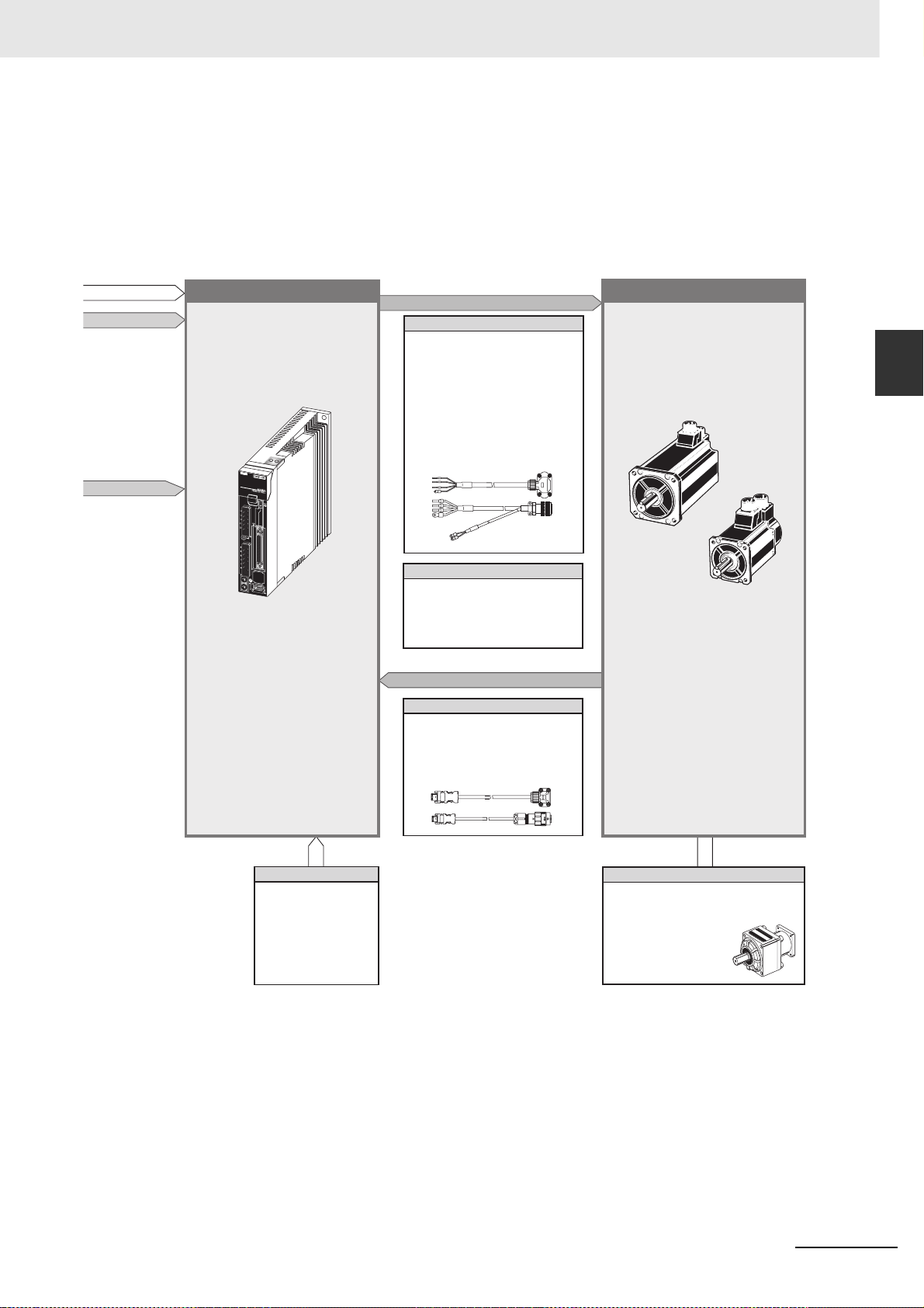
2 Models and External Dimensions
2-1 Servo System Configuration
USB communications
AC Servo Drive
OMNUC G5-series
(Pulse-train Input Type)
AC Servomotor
R88D-KP
200 VAC 3,000 r/min
Motor power signals
Power Cables
Global Non-Flexible Cables
• Without Brake
R88A-CAS
• With Brake
R88A-CA
Global Flexible Cables
• Without Brake
R88A-CA
• With Brake
R88A-CA
BR
B
SR
Brake Cables (50 to 750 W max.)
Global Non-Flexible Cable
R88A-CAGAB
Global Flexible Cable
R88A-CAGABR
Feedback Signals
Encoder Cables
Global Non-Flexible Cable
R88A-CRG
Global Flexible Cable
R88A-CRGR
AC Servomotor
OMNUC G5-series
(Pulse-train Input Type)
AC Servomotor
R88M-KE
2,000 r/min
1,000 r/min
2
Peripheral Devices
Reactors
3G3AX-DL
3G3AX-AL
External Regeneration
Resistors
R88A-RR
Backlash: 3 Arcminutes max.
R88G-HPG
15 Arcminutes max.
R88G-VRSF
OMNUC G5-series (Pulse-train Input Type) AC Servomotors and Servo Drives User’s Manual
Backlash:
Decelerators
2 - 3
Page 42
2 Models and External Dimensions
2-2 How to Read Model Numbers
2-2-1 Servo Drive
The Servo Drive model number tells the Servo Drive type, applicable Servomotor capacity, power
supply voltage, etc.
R88D-KP01H
OMNUC G5-series Servo Drive
Drive Type
P: Pulse-train input type
Maximum Applicable Servomotor Capacity
01: 100 W
02: 200 W
04: 400 W
08: 750 W
10: 1 kW
15: 1.5 kW
20: 2 kW
30: 3 kW
50: 5 kW
Power Supply Voltage
H: 200 VAC
2 - 4
OMNUC G5-series (Pulse-train Input Type) AC Servomotors and Servo Drives User’s Manual
Page 43

2-2-2 Servomotor
A
OMNUC G5-series Servomotor
Motor Type
E: Economy type
2 Models and External Dimensions
2-2 How to Read Model Numbers
R88M-KE10030H-BOS2
2
Servomotor Capacity
050
: 50 W
100
: 100 W
200
: 200 W
400
: 400 W
750
: 750 W
900
: 900 W
1K0
: 1 kW
1K5
: 1.5 kW
2K0
: 2 kW
3K0
: 3 kW
4K0
: 4 kW
5K0
: 5 kW
Rated Rotation Speed
10: 1,000 r/min
20: 2,000 r/min
30: 3,000 r/min
pplied Voltage
H: 200 VAC
Options
Blank: Straight shaft
B: With brake
O: With oil seal
S2: With key and tap
2-2-2 Servomotor
OMNUC G5-series (Pulse-train Input Type) AC Servomotors and Servo Drives User’s Manual
2 - 5
Page 44

2 Models and External Dimensions
A
2-2-3 Decelerator (Backlash: 3 Arcminutes max.)
R88G-HPG14A05100SBJ
Decelerator for G5-Series Servomotor
Backlash: 3 Arcminutes max.
Flange Size Number
11B: 40
14A: 60
20A: 90
32A: 120
50A: 170
65A: 230
Gear Ratio
05: 1/5
09: 1/9 (only for flange number 11A)
11: 1/11 (except for flange number 65A)
20: 1/20 (only for flange number 65A)
21: 1/21 (except for flange number 65A)
25: 1/25 (only for flange number 65A)
33: 1/33
45: 1/45
pplicable Servomotor Capacity
050
: 50 W
100
: 100 W
200
: 200 W
400
: 400 W
750
: 750 W
900
: 900 W
1K0
: 1 kW
1K5
: 1.5 kW
2K0
: 2 kW
3K0
: 3 kW
4K0
5K0
: 4 kW
: 5 kW
Servomotor Type
No: 3,000-r/min Cylinder type
S: 2,000-r/min Servomotors
T: 1,000-r/min Servomotors
Backlash
B: 3 Arcminutes max.
Options
Blank: Straight shaft
J: With key
2 - 6
OMNUC G5-series (Pulse-train Input Type) AC Servomotors and Servo Drives User’s Manual
Page 45

2 Models and External Dimensions
A
2-2-4 Decelerator (Backlash: 15 Arcminutes max.)
R88G-VRSF09B100CJ
Decelerator for G5-Series Servomotor
Backlash: 15 Arcminutes max.
2-2 How to Read Model Numbers
Gear Ratio
05: 1/5
09: 1/9
15: 1/15
25: 1/25
Flange Size Number
B: 52
C: 78
D: 98
pplicable Servomotor Capacity
050
: 50 W
100
: 100 W
200
: 200 W
400
: 400 W
750
: 750 W
Backlash
C: 15 Arcminutes max.
Options
J: With key
2
2-2-4 Decelerator (Backlash: 15 Arcminutes max.)
OMNUC G5-series (Pulse-train Input Type) AC Servomotors and Servo Drives User’s Manual
2 - 7
Page 46
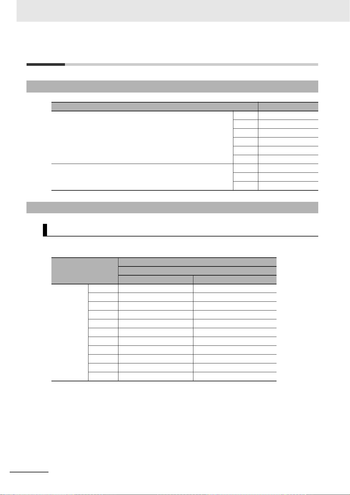
2 Models and External Dimensions
2-3 Model Tables
2-3-1 Servo Drive Model Table
Specifications Model
Single-phase/3-phase 200 VAC 100 W R88D-KP01H
3-phase 200 VAC 2 kW R88D-KP20H
200 W R88D-KP02H
400 W R88D-KP04H
750 W R88D-KP08H
1 kW R88D-KP10H
1.5 kW R88D-KP15H
3 kW R88D-KP30H
5 kW R88D-KP50H
2-3-2 Servomotor Model Tables
3,000-r/min Servomotors
Without brake
Specifications
Straight shaft without key Straight shaft with key and tap
200 V 50 W R88M-KE05030H R88M-KE05030H-S2
100 W R88M-KE10030H R88M-KE10030H-S2
200 W R88M-KE20030H R88M-KE20030H-S2
400 W R88M-KE40030H R88M-KE40030H-S2
750 W R88M-KE75030H R88M-KE75030H-S2
1 kW R88M-KE1K030H R88M -KE1K030H-S2
1.5 kW R88M-KE1K530H R88M-KE1K530H-S2
2 kW R88M-KE2K030H R88M-KE2K030H-S2
3 kW R88M-KE3K030H R88M-KE3K030H-S2
4 kW R88M-KE4K030H R88M-KE4K030H-S2
5 kW R88M-KE5K030H R88M-KE5K030H-S2
Model
With incremental encoder
2 - 8
Note Models with oil seals are also available.
OMNUC G5-series (Pulse-train Input Type) AC Servomotors and Servo Drives User’s Manual
Page 47
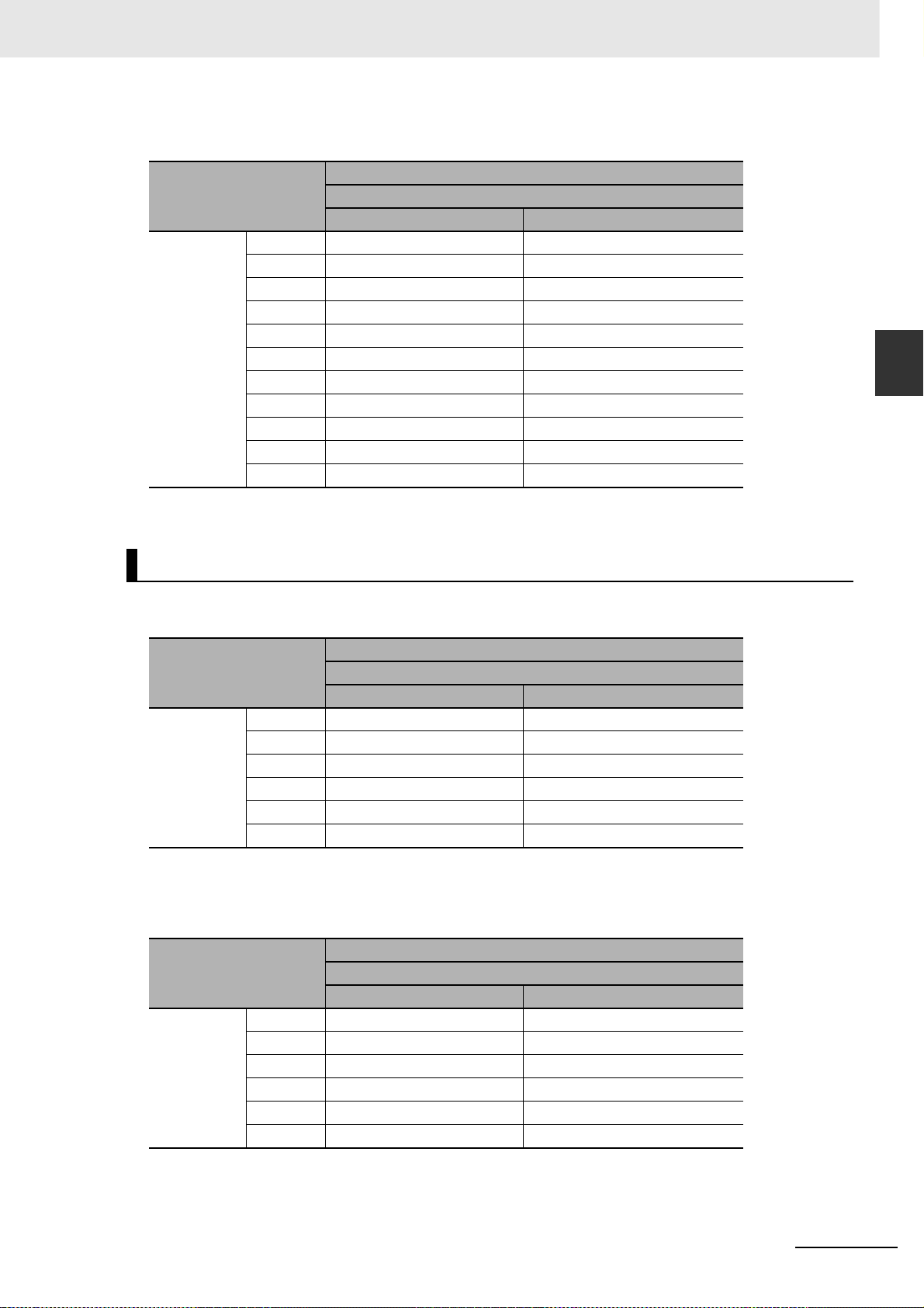
2 Models and External Dimensions
With brake
Model
Specifications
Straight shaft without key Straight shaft with key and tap
200 V 50 W R88M-KE05030H-B R88M-KE05030H-BS2
100 W R88M-KE10030H-B R88M-KE10030H-BS2
200 W R88M-KE20030H-B R88M-KE20030H-BS2
400 W R88M-KE40030H-B R88M-KE40030H-BS2
750 W R88M-KE75030H-B R88M-KE75030H-BS2
1 kW R88M-KE1K030H-B R88M-KE1K030H-BS2
1.5 kW R88M-KE1K530H-B R88M-KE1K530H-BS2
2 kW R88M-KE2K030H-B R88M-KE2K030H-BS2
3 kW R88M-KE3K030H-B R88M-KE3K030H-BS2
4 kW R88M-KE4K030H-B R88M-KE4K030H-BS2
5 kW R88M-KE5K030H-B R88M-KE5K030H-BS2
With incremental encoder
2-3 Model Tables
2
2-3-2 Servomotor Model Tables
Note Models with oil seals are also available.
2,000-r/min Servomotors
Without brake
Model
Specifications
Straight shaft without key Straight shaft with key and tap
200 V 1 kW R88M-KE1K020H R88M-KE1K020H-S2
1.5 kW R88M-KE1K520H R88M-KE1K520H-S2
2 kW R88M-KE2K020H R88M-KE2K020H-S2
3 kW R88M-KE3K020H R88M-KE3K020H-S2
4 kW R88M-KE4K020H R88M-KE4K020H-S2
5 kW R88M-KE5K020H R88M-KE5K020H-S2
Note Models with oil seals are also available.
With brake
Specifications
Straight shaft without key Straight shaft with key and tap
200 V 1 kW R88M-KE1K020H-B R88M-KE1K020H-BS2
1.5 kW R88M-KE1K520H-B R88M-KE1K520H-BS2
2 kW R88M-KE2K020H-B R88M-KE2K020H-BS2
3 kW R88M-KE3K020H-B R88M-KE3K020H-BS2
4 kW R88M-KE4K020H-B R88M-KE4K020H-BS2
5 kW R88M-KE5K020H-B R88M-KE5K020H-BS2
With incremental encoder
Model
With incremental encoder
Note Models with oil seals are also available.
OMNUC G5-series (Pulse-train Input Type) AC Servomotors and Servo Drives User’s Manual
2 - 9
Page 48
2 Models and External Dimensions
1,000-r/min Servomotors
Without brake
Specifications
Straight shaft without key Straight shaft with key and tap
200 V 900 W R88M-KE90 010H R88M-KE90010H-S2
2 kW R88M-KE2K010H R88M-KE2K010H-S2
3 kW R88M-KE3K010H R88M-KE3K010H-S2
With brake
Specifications
Straight shaft without key Straight shaft with key and tap
200 V 900 W R88M-KE90 010H-B R88M-KE90010H-BS2
2 kW R88M-KE2K010H-B R88M-KE2K010H-BS2
3 kW R88M-KE3K010H-B R88M-KE3K010H-BS2
Model
With incremental encoder
Model
With incremental encoder
Note Models with oil seals are also available.
2 - 10
OMNUC G5-series (Pulse-train Input Type) AC Servomotors and Servo Drives User’s Manual
Page 49

2 Models and External Dimensions
2-3-3 Servo Drive and Servomotor Combination Tables
The tables in this section show the possible combinations of OMNUC G5-series (Pulse-train Input T ype)
Servo Drives and Servomotors. The Servomotors and Servo Drives can only be used in the listed
combinations.
“-” at the end of the motor model number is for options, such as the shaft type, brake, oil seal and key.
3,000-r/min Servomotors and Servo Drives
2-3 Model Tables
Voltage
Single-phase/
3-phase 200 V
3-phase 200 V 2 kW R88M-KE2K030H- R88D-KP20H
*1 Use these combination with caution because the Servo Drive and Servomotor have different capacities.
Rated output With incremental encoder
*1
50 W
100 W R88M-KE10030H- R88D-KP01H
200 W R88M-KE20030H- R88D-KP02H
400 W R88M-KE40030H- R88D-KP04H
750 W R88M-KE75030H- R88D-KP08H
*1
1 kW
1.5 kW R88M-KE1K530H- R88D-KP15H
3 kW R88M-KE3K030H- R88D-KP30H
*1
4 kW
5 kW R88M-KE5K030H- R88D-KP50H
Servomotor
R88M-KE05030H- R88D-KP01H
R88M-KE1K030H- R88D-KP15H
R88M-KE4K030H- R88D-KP50H
Servo Drive
2,000-r/min Servomotors and Servo Drives
Voltage
Single-phase/
3-phase 200 V
3-phase 200 V 2 kW R88M-KE2K020H- R88D-KP20H
Rated output With incremental encoder
1 kW R88M-KE1K020H- R88D-KP10H
1.5 kW R88M-KE1K520H- R88D-KP15H
3 kW R88M-KE3K020H- R88D-KP30H
*1
4 kW
5 kW R88M-KE5K020H- R88D-KP50H
Servomotor
R88M-KE4K020H- R88D-KP50H
Servo Drive
2
2-3-3 Servo Drive and Servomotor Combination Tables
*1 Use these combination with caution because the Servo Drive and Servomotor have different capacities.
1,000-r/min Servomotors and Servo Drives
Voltage
Single-phase/
3-phase 200 V
3-phase 200 V
*1 Use these combination with caution because the Servo Drive and Servomotor have different capacities.
OMNUC G5-series (Pulse-train Input Type) AC Servomotors and Servo Drives User’s Manual
Rated output With incremental encoder
*1
900 W
*1
2 kW
*1
3 kW
Servomotor
R88M-KE90010H- R88D-KP15H
R88M-KE2K010H- R88D-KP30H
R88M-KE3K010H- R88D-KP50H
Servo Drive
2 - 11
Page 50
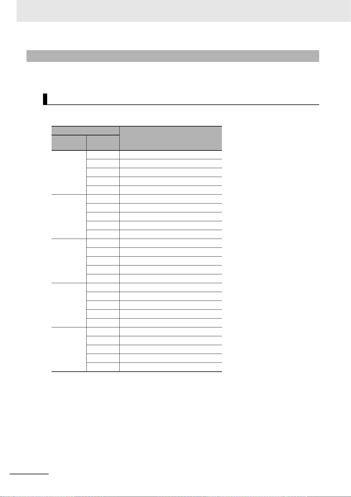
2 Models and External Dimensions
2-3-4 Decelerator Model Tables
The following tables list the Decelerator models for OMNUC G5-series Servomotors. Select a
decelerator based on the Servomotor capacity.
Backlash: 3 Arcminutes max.
For 3,000-r/min Servomotors
Specifications
Servomotor
capacity
50 W 1/5 R88G-HPG11B05100B
100 W 1/5 R88G-HPG11B05100B
200 W 1/5 R88G-HPG14A05200B
400 W 1/5 R88G-HPG14A05400B
750 W 1/5 R88G-HPG20A05750B
Gear ratio
1/9 R88G-HPG11B09050B
1/21 R88G-HPG14A21100B
1/33 R88G-HPG14A33050B
1/45 R88G-HPG14A45050B
1/11 R88G-HPG14A11100B
1/21 R88G-HPG14A21100B
1/33 R88G-HPG20A33100B
1/45 R88G-HPG20A45100B
1/11 R88G-HPG14A11200B
1/21 R88G-HPG20A21200B
1/33 R88G-HPG20A33200B
1/45 R88G-HPG20A45200B
1/11 R88G-HPG20A11400B
1/21 R88G-HPG20A21400B
1/33 R88G-HPG32A33400B
1/45 R88G-HPG32A45400B
1/11 R88G-HPG20A11750B
1/21 R88G-HPG32A21750B
1/33 R88G-HPG32A33750B
1/45 R88G-HPG32A45750B
Model
2 - 12
OMNUC G5-series (Pulse-train Input Type) AC Servomotors and Servo Drives User’s Manual
Page 51

Specifications
Servomotor
capacity
1 kW 1/5 R88G-HPG32A052K0B
1.5 kW 1/5 R88G-HPG32A052K0B
2 kW 1/5 R88G-HPG32A052K0B
3 kW 1/5 R88G-HPG32A053K0B
4 kW 1/5 R88G-HPG32A054K0B
5 kW 1/5 R88G-HPG50A055K0B
Gear ratio
1/11 R88G-HPG32A112K0B
1/21 R88G-HPG32A211K5B
1/33 R88G-HPG50A332K0B
1/45 R88G-HPG50A451K5B
1/11 R88G-HPG32A112K0B
1/21 R88G-HPG32A211K5B
1/33 R88G-HPG50A332K0B
1/45 R88G-HPG50A451K5B
1/11 R88G-HPG32A112K0B
1/21 R88G-HPG50A212K0B
1/33 R88G-HPG50A332K0B
1/11 R88G-HPG50A113K0B
1/21 R88G-HPG50A213K0B
1/11 R88G-HPG50A115K0B
1/11 R88G-HPG50A115K0B
Model
2 Models and External Dimensions
2-3 Model Tables
2
2-3-4 Decelerator Model Tables
Note 1 The standard shaft type is a straight shaft.
2 A model with a key and tap is indicated with J at the end of the model number (the suffix shown in the box).
(Example: R88G-HPG11A05100BJ)
OMNUC G5-series (Pulse-train Input Type) AC Servomotors and Servo Drives User’s Manual
2 - 13
Page 52

2 Models and External Dimensions
For 2,000-r/min Servomotors
Specifications
Servomotor
capacity
1 kW 1/5 R8 8G-HPG32A053K0B
1.5 kW 1/5 R88G-HP G3 2A053K0B
2 kW 1/5 R8 8G-HPG32A053K0B
3 kW 1/5 R8 8G-HPG32A054K0B
4 kW 1/5 R8 8G-HPG50A055K0SB
5 kW 1/5 R8 8G-HPG50A055K0SB
Gear ratio
1/11 R88G-HPG32A112K0SB
1/21 R88G-HPG32A211K0SB
1/33 R88G-HPG50A332K0SB
1/45 R88G-HPG50A451K0SB
1/11 R88G-HPG32A112K0SB
1/21 R88G-HPG50A213K0B
1/33 R88G-HPG50A332K0SB
1/11 R88G-HPG32A112K0SB
1/21 R88G-HPG50A213K0B
1/33 R88G-HPG50A332K0SB
1/11 R88G-HPG50A115K0B
1/21 R88G-HPG50A213K0SB
1/25 R88G-HPG65A253K0SB
1/11 R88G-HPG50A115K0SB
1/20 R88G-HPG65A205K0SB
1/25 R88G-HPG65A255K0SB
1/11 R88G-HPG50A115K0SB
1/20 R88G-HPG65A205K0SB
1/25 R88G-HPG65A255K0SB
Model
2 - 14
Note 1 The standard shaft type is a straight shaft.
2 A model with a key and tap is indicated with J at the end of the model number (the suffix shown in the box).
(Example: R88G-HPG32A053K0BJ)
OMNUC G5-series (Pulse-train Input Type) AC Servomotors and Servo Drives User’s Manual
Page 53

For 1,000-r/min Servomotors
Specifications
Servomotor
capacity
900 W 1/5 R88G-HPG32A05900TB
2 kW 1/5 R88G-HPG32A052K0TB
3 kW 1/5 R88G-HPG50A055K0SB
Gear ratio
1/11 R88G-HPG32A11900TB
1/21 R88G-HPG50A21900TB
1/33 R88G-HPG50A33900TB
1/11 R88G-HPG50A112K0TB
1/21 R88G-HPG50A212K0TB
1/25 R88G-HPG65A255K0SB
1/11 R88G-HPG50A115K0SB
1/20 R88G-HPG65A205K0SB
1/25 R88G-HPG65A255K0SB
2 Models and External Dimensions
Model
2-3 Model Tables
2
2-3-4 Decelerator Model Tables
Note 1 The standard shaft type is a straight shaft.
2 A model with a key and tap is indicated with J at the end of the model number (the suffix shown in the box).
(Example: R88G-HPG32A05900TBJ)
Backlash: 15 Arcminutes max.
For 3,000-r/min Servomotors (Straight Shaft with Key)
Specifications
Servomotor
capacity
50 W 1/5 R88G-VRSF05B100CJ
100 W 1/5 R88G-VRSF05B100CJ
200 W 1/5 R88G-VRSF05B200CJ
400 W 1/5 R88G-VRSF05C400CJ
750 W 1/5 R88G-VRSF05C750CJ
Gear ratio
1/9 R88G-VRSF09B100CJ
1/15 R88G-VRSF15B100CJ
1/25 R88G-VRSF25B100CJ
1/9 R88G-VRSF09B100CJ
1/15 R88G-VRSF15B100CJ
1/25 R88G-VRSF25B100CJ
1/9 R88G-VRSF09C200CJ
1/15 R88G-VRSF15C200CJ
1/25 R88G-VRSF25C200CJ
1/9 R88G-VRSF09C400CJ
1/15 R88G-VRSF15C400CJ
1/25 R88G-VRSF25C400CJ
1/9 R88G-VRSF09D750CJ
1/15 R88G-VRSF15D750CJ
1/25 R88G-VRSF25D750CJ
Model
OMNUC G5-series (Pulse-train Input Type) AC Servomotors and Servo Drives User’s Manual
2 - 15
Page 54

2 Models and External Dimensions
2-3-5 Cable and Peripheral Device Model Tables
Encoder Cables (Global Non-Flexible Cable)
Specifications Model
[200 V]
For 3,000-r/min Servomotors of 50 to 750 W
[200 V]
3,000-r/min Servomotors of 1.0 kW or more
For 2,000-r/min Servomotors
For 1,000-r/min Servomotors
3 m R88A-CRGB003C
5 m R88A-CRGB005C
10 m R88A-CRGB010C
15 m R88A-CRGB015C
20 m R88A-CRGB020C
3 m R88A-CRGC003N
5 m R88A-CRGC005N
10 m R88A-CRGC010N
15 m R88A-CRGC015N
20 m R88A-CRGC020N
Motor Power Cables (Global Non-Flexible Cable)
Specifications
[200 V]
For 3,000-r/min Servomotors of 50 to 750 W
For 3,000-r/min Servomotors of 1 to 2 kW
For 2,000-r/min Servomotors of 1 to 2 kW
For 1,000-r/min Servomotors of 900 W
For 3,000-r/min Servomotors of 3 to 5 kW
For 2,000-r/min Servomotors of 3 to 5 kW
For 1,000-r/min Servomotors of 2 to 3 kW
3 m R88A-CAGA003S –
5 m R88A-CAGA005S –
10 m R88A-CAGA010S –
15 m R88A-CAGA015S –
20 m R88A-CAGA020S –
3 m R88A-CAGB003S R88A-CAGB003B
5 m R88A-CAGB005S R88A-CAGB005B
10 m R88A-CAGB010S R88A-CAGB010B
15 m R88A-CAGB015S R88A-CAGB015B
20 m R88A-CAGB020S R88A-CAGB020B
3 m R88A-CAGD003S R88A-CAGD003B
5 m R88A-CAGD005S R88A-CAGD005B
10 m R88A-CAGD010S R88A-CAGD010B
15 m R88A-CAGD015S R88A-CAGD015B
20 m R88A-CAGD020S R88A-CAGD020B
For motor without brake For motor with brake
Brake Cables (Global Non-Flexible Cable)
Model
2 - 16
Specifications Model
[200 V]
For 3,000-r/min Servomotors of 50 to 750 W
OMNUC G5-series (Pulse-train Input Type) AC Servomotors and Servo Drives User’s Manual
3 m R88A-CAGA003B
5 m R88A-CAGA005B
10 m R88A-CAGA010B
15 m R88A-CAGA015B
20 m R88A-CAGA020B
Page 55
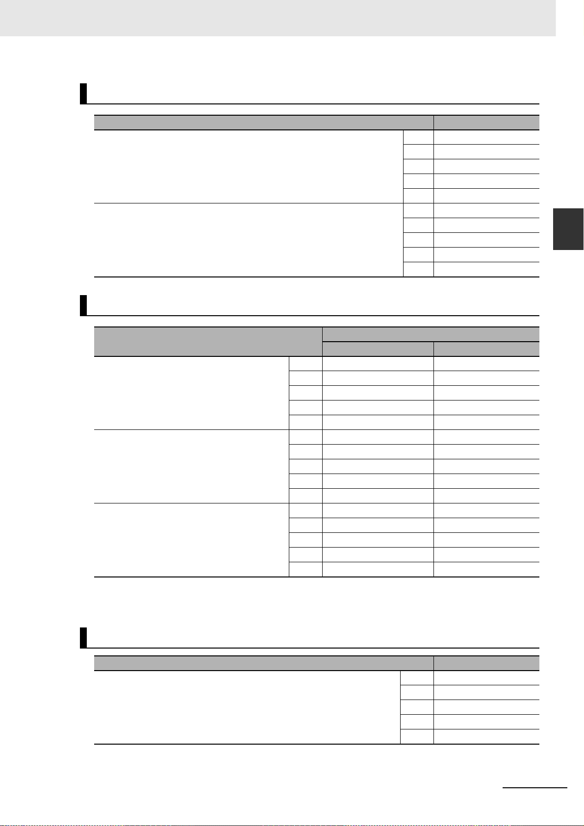
2 Models and External Dimensions
Encoder Cables (Global Flexible Cable)
Specifications Model
[200 V]
For 3,000-r/min Servomotors of 50 to 750 W
[200 V]
3,000-r/min Servomotors of 1.0 kW or more
For 2,000-r/min Servomotors
For 1,000-r/min Servomotors
Motor Power Cables (Global Flexible Cable)
3 m R88A-CRGB003CR
5 m R88A-CRGB005CR
10 m R88A-CRGB010CR
15 m R88A-CRGB015CR
20 m R88A-CRGB020CR
3 m R88A-CRGC003NR
5 m R88A-CRGC005NR
10 m R88A-CRGC010NR
15 m R88A-CRGC015NR
20 m R88A-CRGC020NR
2-3 Model Tables
2
2-3-5 Cable and Peripheral Device Model Tables
Specifications
[200 V]
For 3,000-r/min Servomotors of 50 to 750 W
10 m R88A-CAGA010SR –
15 m R88A-CAGA015SR –
20 m R88A-CAGA020SR –
[200 V]
For 3,000-r/min Servomotors of 1 to 2 kW
For 2,000-r/min Servomotors of 1 to 2 kW
For 1,000-r/min Servomotors of 900 W
For 3,000-r/min Servomotors of 3 to 5 kW
For 2,000-r/min Servomotors of 3 to 5 kW
For 1,000-r/min Servomotors of 2 to 3 kW
Note Different connectors are used for the motor power and the brake on 200-V 3,000-r/min Servomotors of 50 to
750 W. When using a Servomotor with a brake, tw o cab les are required: a Power Cable without Brake and a
Brake Cable.
10 m R88A-CAGB010SR R88A-CAGB010BR
15 m R88A-CAGB015SR R88A-CAGB015BR
20 m R88A-CAGB020SR R88A-CAGB020BR
10 m R88A-CAGD010SR R88A-CAGD010BR
15 m R88A-CAGD015SR R88A-CAGD015BR
20 m R88A-CAGD020SR R88A-CAGD020BR
For motor without brake For motor with brake
3 m R88A-CAGA003SR –
5 m R88A-CAGA005SR –
3 m R88A-CAGB003SR R88A-CAGB003BR
5 m R88A-CAGB005SR R88A-CAGB005BR
3 m R88A-CAGD003SR R88A-CAGD003BR
5 m R88A-CAGD005SR R88A-CAGD005BR
Model
Brake Cables (Global Flexible Cable)
Specifications Model
[200 V]
For 3,000-r/min Servomotors of 50 to 750 W
OMNUC G5-series (Pulse-train Input Type) AC Servomotors and Servo Drives User’s Manual
3 m R88A-CAGA003BR
5 m R88A-CAGA005BR
10 m R88A-CAGA010BR
15 m R88A-CAGA015BR
20 m R88A-CAGA020BR
2 - 17
Page 56

2 Models and External Dimensions
Analog Monitor Cable
Specifications Model
Analog Monitor Cable 1 m R88A-CMK001S
Connectors
Specifications Model
Motor Connector for Encoder Cable [200 V]
Control I/O Connector (CN1) R88A-CNU11C
Encoder Connector (CN2) R88A-CNW01R
Power Cable Connector (for 750 W max.) R88A-CNG01A
Brake Cable Connector (for 750 W max.) R88A-CNG01B
R88A-CNG02R
For 3,000-r/min of 50 to 750 W
Servo Relay Units (for CN1)
Specifications Model
Servo Relay Unit For CS1W-NC113/-NC133
For CJ1W-NC113/-NC133
For C200HW-NC113
For CS1W-NC213/-NC413/-NC233/-NC433
For CJ1W-NC213/-NC413/-NC233/-NC433
For C200HW-NC213/-NC413
For CJ2M-CPU31/-CPU32/-CPU33/-CPU34/-CPU35
For CJ2M-CPU11/-CPU12/-CPU13/-CPU14/-CPU15
For FQM1-MMP22 XW2B-80J7-12A
For CQM1-CPU43-V1 XW2B-20J6-3B
XW2B-20J6-1B
XW2B-40J6-2B
XW2B-20J6-8A
XW2B-40J6-9A
2 - 18
OMNUC G5-series (Pulse-train Input Type) AC Servomotors and Servo Drives User’s Manual
Page 57

Servo Relay Unit Cables (Servo Drive)
Specifications Model
Servo Drive Cable For NC Unit (XW2B-J6-B)
For CQM1 (XW2B-20J6-3B)
For CJ2M-CPU31/-CPU32/-CPU33/-CPU34/-CPU35
For CJ2M-CPU11/-CPU12/-CPU13/-CPU14/-CPU15
(XW2B-20J6-8A/XW2B-40J6-9A)
For FQM1-MMP22
(XW2B-80J7-12A)
2 Models and External Dimensions
1 m XW2Z-100J-B25
2 m XW2Z-200J-B25
1 m XW2Z-100J-B31
2 m XW2Z-200J-B31
1 m XW2Z-100J-B26
2 m XW2Z-200J-B26
2-3 Model Tables
2
Servo Relay Unit Cables (Position Control Unit)
Specifications Model
Position Control
Unit Cable
For CS1W-NC113, C200HW-NC113
(XW2B-20J6-1B)
For CS1W-NC213/-NC413, C200HW-NC213/-NC413
(XW2B-20J6-2B)
For CS1W-NC133 (XW2B-20J6-1B) 0.5 m XW2Z-050J-A10
For CS1W-NC233/-NC433 (XW2B-20J6-2B) 0.5 m XW2Z-050J-A11
For CJ1W-NC113 (XW2B-20J6-1B) 0.5 m XW2Z-050J-A14
For CJ1W-NC213/-NC413 (XW2B-20J6-2B) 0.5 m XW2Z-050J-A15
For CJ1W-NC133 (XW2B-20J6-1B) 0.5 m XW2Z-050J-A18
For CJ1W-NC233/-NC433 (XW2B-20J6-2B) 0.5 m XW2Z-050J-A19
For CJ2M-CPU31/-CPU32/-CPU33/-CPU34/-CPU35
For CJ2M-CPU11/-CPU12/-CPU13/-CPU14/-CPU15
(XW2B-20J6-8A/XW2B-40J6-9A)
For FQM1-MMP22
(XW2B-80J7-12A)
General-Purpose I/O 0.5 m XW2Z-050J-A28
Special I/O 0.5 m XW2Z-050J-A30
2-3-5 Cable and Peripheral Device Model Tables
0.5 m XW2Z-050J-A6
1 m XW2Z-100J-A6
0.5 m XW2Z-050J-A7
1 m XW2Z-100J-A7
1 m XW2Z-100J-A10
1 m XW2Z-100J-A11
1 m XW2Z-100J-A14
1 m XW2Z-100J-A15
1 m XW2Z-100J-A18
1 m XW2Z-100J-A19
0.5 m XW2Z-050J-A33
1 m XW2Z-100J-A33
1 m XW2Z-100J-A28
2 m XW2Z-200J-A28
1 m XW2Z-100J-A30
2 m XW2Z-200J-A30
OMNUC G5-series (Pulse-train Input Type) AC Servomotors and Servo Drives User’s Manual
2 - 19
Page 58

2 Models and External Dimensions
Control Cables
Specifications Model
Specified cables for Position Control Unit (for line driver output 1 axis)
CJ1W-NC234/-NC434
Specified cables for Position Control Unit (for open collector output 1 axis)
CJ1W-NC214/-NC414
Specified cables for Position Control Unit (for line driver output 2 axes)
CJ1W-NC234/-NC434
Specified cables for Position Control Unit (for open collector output 2 axes)
CJ1W-NC214/-NC414
General-purpose Control Cables (with connector on one end) 1 m R88A-CPG001S
Connector Terminal Block Cables 1 m XW2Z-100J-B24
Connector Terminal Block M3 screws XW2B-50G4
1 m XW2Z-100J-G9
5 m XW2Z-500J-G9
10 m XW2Z-10MJ-G9
1 m XW2Z-100J-G13
3 m XW2Z-300J-G13
1 m XW2Z-100J-G1
5 m XW2Z-500J-G1
10 m XW2Z-10MJ-G1
1 m XW2Z-100J-G5
3 m XW2Z-300J-G5
2 m R88A-CPG002S
2 m XW2Z-200J-B24
M3.5 screws XW2B-50G5
M3 screws XW2D-50G6
External Regeneration Resistors
Specifications Model
Regeneration process capacity: 20 W, 50 Ω (with 150°C thermal sensor) R88A-RR08050S
Regeneration process capacity: 20 W, 100 Ω (with 150°C thermal sensor) R88A-RR080100S
Regeneration process capacity: 70 W, 47 Ω (with 170°C thermal sensor) R88A-RR22047S
Regeneration process capacity: 70 W, 47 Ω (with 150°C thermal sensor) R88A-RR22047S1
Regeneration process capacity: 180 W, 20 Ω (with 200°C thermal sensor) R88A-RR50020S
2 - 20
OMNUC G5-series (Pulse-train Input Type) AC Servomotors and Servo Drives User’s Manual
Page 59

2 Models and External Dimensions
Reactors
Specifications Model Reactor type
R88D-KP01H (For single-phase input) 3G3AX-DL2002 DC reactor
R88D-KP02H (For single-phase input) 3G3AX-DL2004
R88D-KP04H (For single-phase input) 3G3AX-DL2007
R88D-KP08H/-KP10H (For single-phase input) 3G3AX-DL2015
R88D-KP15H (For single-phase input) 3G3AX-DL2022
R88D-KP01H/-KP02H/-KP04H/
-KP08H/-KP10H/-KP15H (For 3-phase input)
R88D-KP20H/-KP30H 3G3AX-AL2055
R88D-KP50H 3G3AX-AL2110
3G3AX-AL2025 A C reactor
Mounting Brackets (L-brackets for Rack Mounting)
2-3 Model Tables
2
2-3-5 Cable and Peripheral Device Model Tables
Specifications Model
R88D-KP01H/-KP02H R88A-TK01K
R88D-KP04H R88A-TK02K
R88D-KP08H R88A-TK03K
R88D-KP10H/-KP15H R88A-TK04K
OMNUC G5-series (Pulse-train Input Type) AC Servomotors and Servo Drives User’s Manual
2 - 21
Page 60
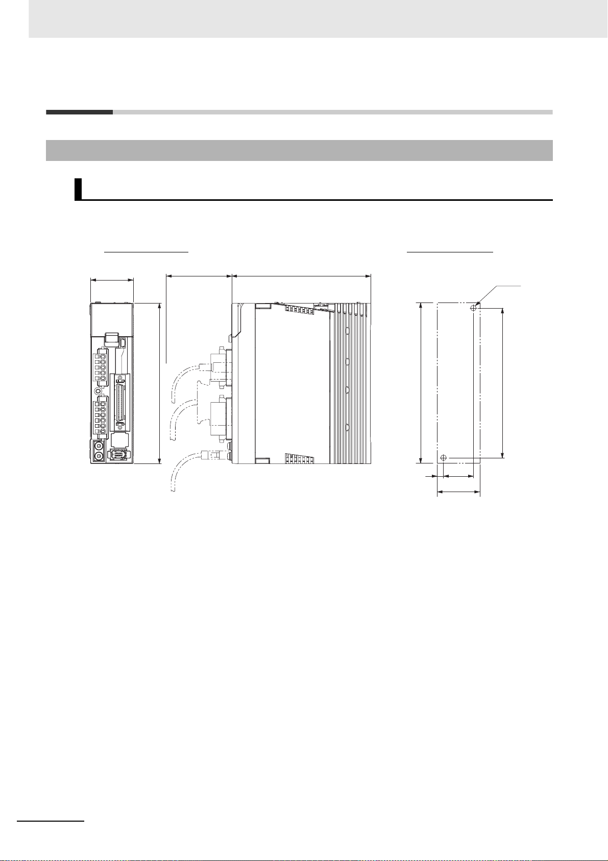
2 Models and External Dimensions
2-4 External and Mounting Dimensions
2-4-1 Servo Drive Dimensions
Single-phase/3-phase 200 VAC: R88D-KP01H/-KP02H (100 to 200 W)
Wall Mounting
External Dimensions Mounting dimensions
40
150
13070
150
6
28
40
2-M4
140
2 - 22
OMNUC G5-series (Pulse-train Input Type) AC Servomotors and Servo Drives User’s Manual
Page 61
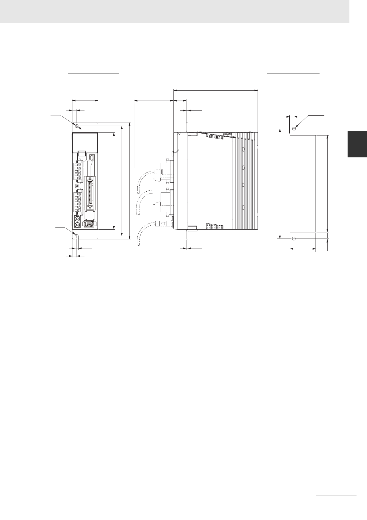
2 Models and External Dimensions
Front Mounting (Using Front Mounting Brackets)
2-4 External and Mounting Dimensions
External Dimensions
7
φ5.2
R26
7
40
5.2
150
170
180
Mounting dimensions
130
70
19.5
2.5
8
2-M4
2
2-4-1 Servo Drive Dimensions
Rectangular
170
2.5
(42)*
* Rectangular hole dimensions are reference values.
hole
(158)*
6
OMNUC G5-series (Pulse-train Input Type) AC Servomotors and Servo Drives User’s Manual
2 - 23
Page 62

2 Models and External Dimensions
Single-phase/3-phase 200 VAC: R88D-KP04H (400 W)
Wall Mounting
External Dimensions Mounting dimensions
55
150
70
130
Front Mounting (Using Front Mounting Brackets)
External Dimensions
150
6
43
55
Mounting dimensions
2-M4
140
φ5.2
R2.6
55
47
7
180
170
150
5.2
7
70
19.5
2.5
2.5
130
8
170
2-M4
Rectangular
hole
(57)*
(158)*
6
* Rectangular hole dimensions are reference values.
2 - 24
OMNUC G5-series (Pulse-train Input Type) AC Servomotors and Servo Drives User’s Manual
Page 63

2 Models and External Dimensions
Single-phase/3-phase 200 VAC: R88D-KP08H (750 W)
Wall Mounting
External Dimensions Mounting dimensions
2-4 External and Mounting Dimensions
65
150
70
170
Front Mounting (Using Front Mounting Brackets)
External Dimensions
φ5.2
65
40
20
70
19.5
2.5
170
4
2-M4
2
2-4-1 Servo Drive Dimensions
150
7.5
50
65
Mounting dimensions
4
21
140
2-M4
180
170
150
R2.6
5.2
20
40
2.5
* Rectangular hole dimensions are reference values.
OMNUC G5-series (Pulse-train Input Type) AC Servomotors and Servo Drives User’s Manual
170
Rectangular
hole
(67)*
(158)*
6
2 - 25
Page 64
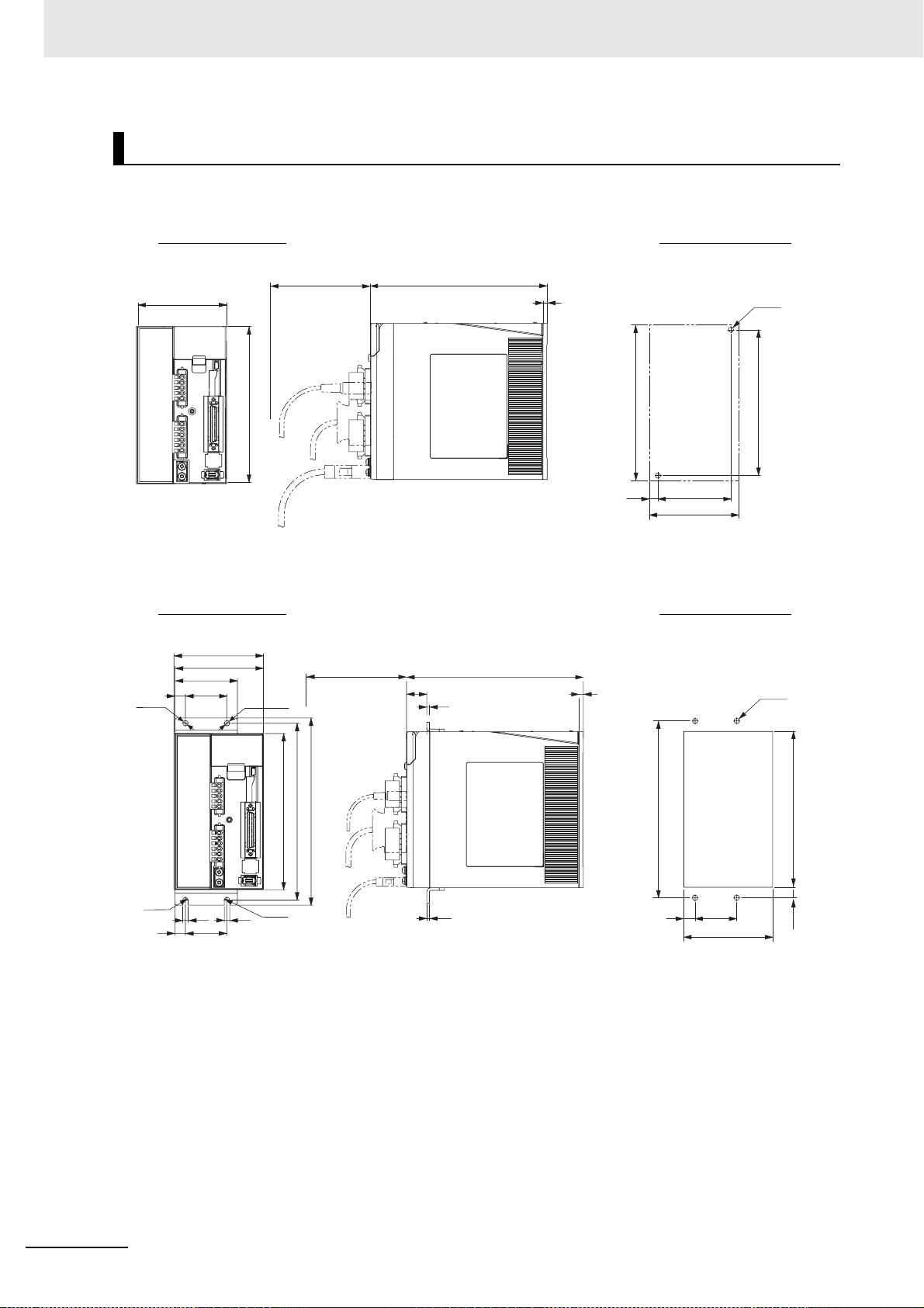
2 Models and External Dimensions
Single-phase/3-phase 200 VAC: R88D-KP10H/-KP15H (900 W to 1.5 kW)
Wall Mounting
External Dimensions Mounting dimensions
70
86
150
170
4
150
8.5
70
86
Front Mounting (Using Front Mounting Brackets)
External Dimensions Mounting dimensions
86
φ5.2
85
60
10
40
φ5.2
70
19.5
2.5
170
4
2-M4
140
4-M4
R2.6
170
180
150
5.2
R2.6
5.2
10
40
2.5
170
12
Rectangular
hole
40
(88)*
(158)*
6
* Rectangular hole dimensions are reference values.
2 - 26
OMNUC G5-series (Pulse-train Input Type) AC Servomotors and Servo Drives User’s Manual
Page 65

3-phase 200 VAC: R88D-KP20H (2 kW)
Wall Mounting
External Dimensions
86
85
5017.5
R2.6 R2.6
42.5
5.2
5.2
φ5.2
168
188
198
70
2 Models and External Dimensions
2-4 External and Mounting Dimensions
193.5
3.5
2
2-4-1 Servo Drive Dimensions
R2.6
17.5
42.5
50
Mounting dimensions
25
168
18.5
50
86
5.25.2
6-M4
188
φ5.2
R2.6
OMNUC G5-series (Pulse-train Input Type) AC Servomotors and Servo Drives User’s Manual
2 - 27
Page 66
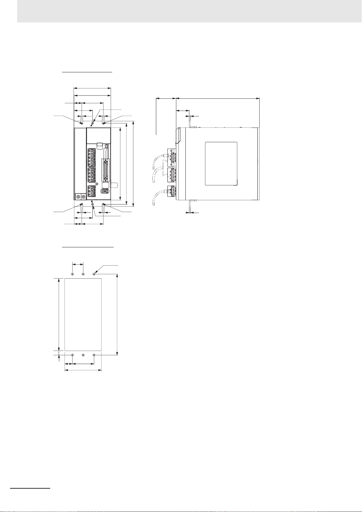
2 Models and External Dimensions
Front Mounting (Using Front Mounting Brackets)
External Dimensions
86
85
5017.5
R2.6
42.5
5.2
5.2
φ5.2
168
R2.6
188
198
70
30.7
193.5
2.5
R2.6
17.5
42.5
50
R2.6
5.25.2
φ5.2
Mounting dimensions
(176)*
6
19.5
25
Rectangular
hole
50
(88)*
6-M4
188
* Rectangular hole dimensions are reference values.
2.5
2 - 28
OMNUC G5-series (Pulse-train Input Type) AC Servomotors and Servo Drives User’s Manual
Page 67

2 Models and External Dimensions
3-phase 200 VAC: R88D-KP30H/-KP50H (3 to 5 kW)
Wall Mounting
External Dimensions
2-4 External and Mounting Dimensions
5.2
5.2
130
100
100
φ5.2
5.2
5.2
φ5.2
R2.6
65
65
15
R2.6
R2.6 R2.6
15
220
240
250
70
212
3
2
2-4-1 Servo Drive Dimensions
Mounting dimensions
50
220
15
100
130
6-M4
240
OMNUC G5-series (Pulse-train Input Type) AC Servomotors and Servo Drives User’s Manual
2 - 29
Page 68

2 Models and External Dimensions
Front Mounting (Using Front Mounting Brackets)
External Dimensions
R2.6
70
40.7
2.5
2.5
5.2
5.2
130
100
100
φ5.2
5.2
5.2
φ5.2
R2.6
R2.6R2.6
220
240
250
65
65
15
15
212
Mounting dimensions
6-M4
240
(228)*
Rectangular hole
6
16
50
100
(132)*
* Rectangular hole dimensions are reference values.
2 - 30
OMNUC G5-series (Pulse-train Input Type) AC Servomotors and Servo Drives User’s Manual
Page 69

2-4-2 Servomotor Dimensions
3,000-r/min Servomotors (200 V)
50 W/100 W (without Brake)
R88M-KE05030H (-S2)/-KE10030H (-S2)
Encoder connector
Motor connector
2 Models and External Dimensions
2-4 External and Mounting Dimensions
200
13
25
40
(
)
27
)
(
20
(1)
R
3
6
φ 8 h6
1.5 min.
3.7
φ 30 h7
(Shaft end specifications with key and tap)
25
14
12.5
n
46
`
0.2
R
4.2
2-φ4.3
3h9
(Key groove P9)
3
M3 (depth 6)
6.2
Dimensions [mm]
LL LM LN
24
230
LM
LL
2
LN
Model
R88M-KE05030 72 48 26.5
R88M-KE10030 92 68 46.5
Note The standard models have a straight shaft. Models with a key and tap are indicated with S2 at the end of the
model number.
Models with an oil seal are indicated with O at the end of the model number. The motor dimensions do not
change.
50 W/100 W (with Brake)
R88M-KE05030H-B (S2)/-KE10030H-B (S2)
Encoder connector
Brake connector
Motor connector
2
2-4-2 Servomotor Dimensions
LL
24
230
LM
LN
Model
25
40
(27)
)
20
3.7
(
(1)
200
36
)
13
(
2
1.5 min.
R
φ 8 h6
h7
30
φ
(Shaft end specifications with key and tap)
25
n
46
`
0.2
R
4.2
2-φ4.3
Dimensions [mm]
LL LM LN
R88M-KE05030-B 102 78 26.5
R88M-KE10030-B 122 98 46.5
Note The standard models have a straight shaft. Models with a key and tap are indicated with S2 at the end of the
model number.
Models with an oil seal are indicated with O at the end of the model number. The motor dimensions do not
change.
OMNUC G5-series (Pulse-train Input Type) AC Servomotors and Servo Drives User’s Manual
14
12.5
(Key groove P9)
3
M3 (depth 6)
6.2
3h9
2 - 31
Page 70
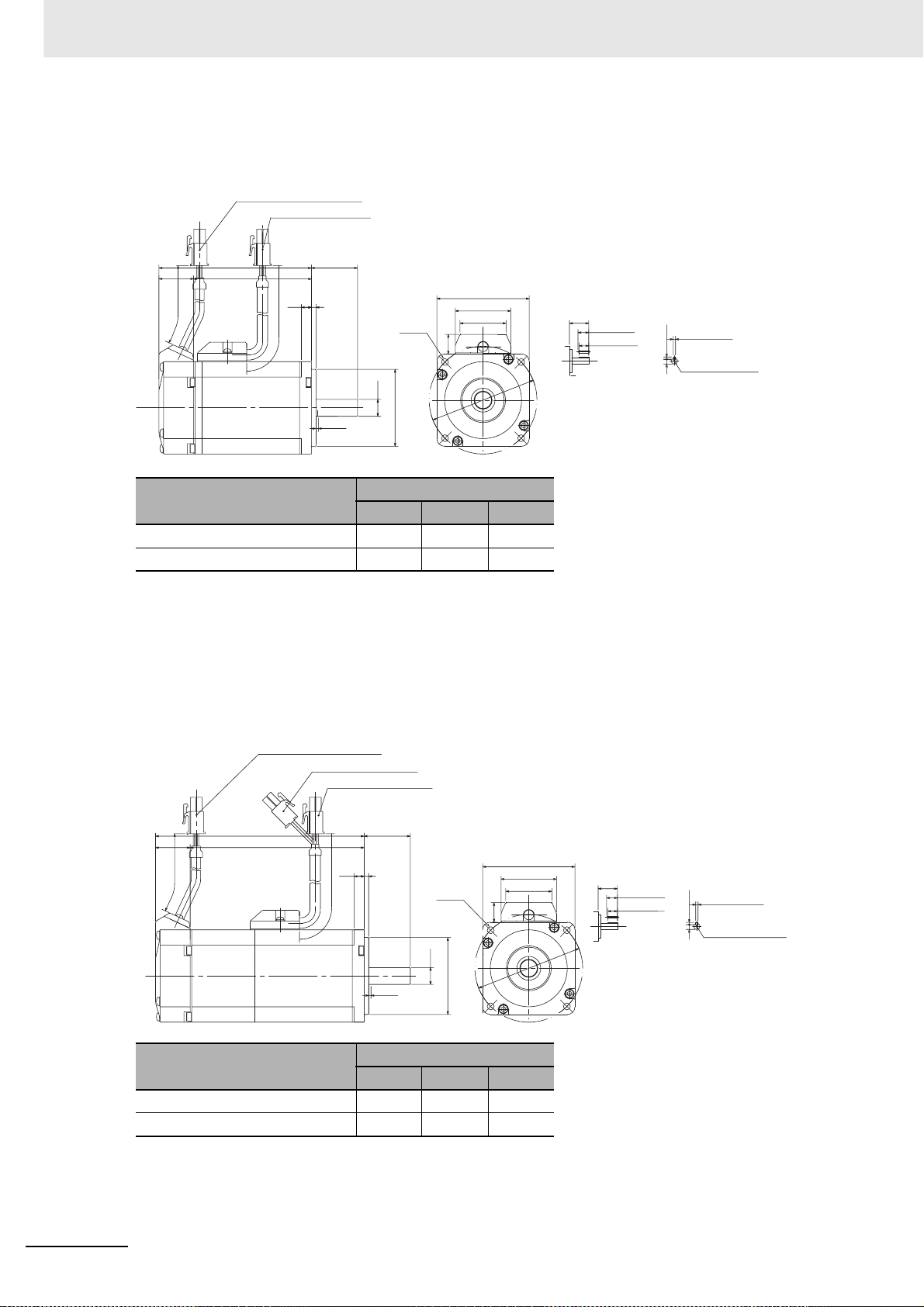
2 Models and External Dimensions
200 W/400 W (without Brake)
R88M-KE20030 (-S2)/-KE40030 (-S2)
Encoder connector
Motor connector
22.5
220
LL
LM
Model
200
6.5
30
(13)
60
(36)
(30)
`
70
n
3
4-φ4.5
φSh6
φ50h7
1.5 min.
(Shaft end specifications with key and tap)
20 (200 W)
0.2
30
25 (400 W)
18 (200 W)
22.5 (400 W)
4h9 (200 W)
5h9 (400 W)
(Key groove P9)
4 (200 W)
5 (400 W)
M4 depth 8 (200 W)
M5 depth 10 (400 W)
11
8.5
Dimensions [mm]
LL LM S
R88M-KE20030 79.5 57 11
R88M-KE40030 99 76.5 14
Note The standard models have a straight shaft. Models with a key and tap are indicated with S2 at the end of the
model number.
Models with an oil seal are indicated with O at the end of the model number. The motor dimensions do not
change.
200 W/400 W (with Brake)
R88M-KE20030-B (S2)/-KE40030-B (S2)
Encoder connector
Brake connector
Motor connector
22.5
220
LM
6.5
200
Model
30LL
3
4-φ4.5
(13)
φSh6
1.5 min.
φ50h7
Dimensions [mm]
LL LM S
60
(36)
(30)
(Shaft end specifications with key and tap)
20 (200 W)
30
25 (400 W)
18 (200 W)
22.5 (400 W)
0.2
`
70
n
4h9 (200 W)
5h9 (400 W)
(Key groove P9)
4 (200W)
5 (400W)
M4 depth 8 (200 W)
M5 depth 10 (400 W)
11
8.5
R88M-KE20030-B 116 93.5 11
R88M-KE40030-B 135.5 113 14
Note The standard models have a straight shaft. Models with a key and tap are indicated with S2 at the end of the
model number.
Models with an oil seal are indicated with O at the end of the model number. The motor dimensions do not
change.
2 - 32
OMNUC G5-series (Pulse-train Input Type) AC Servomotors and Servo Drives User’s Manual
Page 71

750 W (without Brake)
R88M-KE75030H (-S2)
Encoder connector
Motor connector
2 Models and External Dimensions
2-4 External and Mounting Dimensions
25.5
220
112.2
86.7
200
35
38
φ70h7
φ19h6
1.5 min.
(13)
80
(36)
(
30
)
`
0.2
90
n
(Shaft end specifications
with key and tap)
35
4-φ6
25
22
6
(Key groove P9)
15.5
6h9
M5 depth 10
Note The standard models have a straight shaft. Models with a key and tap are indicated with S2 at the end of the
model number.
Models with an oil seal are indicated with O at the end of the model number. The motor dimensions do not
change.
750 W (with Brake)
R88M-KE75030H-B (S2)
Encoder connector
Brake connector
Motor connector
2
2-4-2 Servomotor Dimensions
220
149.2 35
123.725.5
8
200
3
1.5 min.
φ19h6
φ70h7
80
(36)
(30)
)
(13
0.2
`
90
n
(Shaft end specifications
with key and tap)
35
25
4-φ6
22
(Key groove P9)
6
15.5
6h9
M5 depth 10
Note The standard models have a straight shaft. Models with a key and tap are indicated with S2 at the end of the
model number.
Models with an oil seal are indicated with O at the end of the model number. The motor dimensions do not
change.
OMNUC G5-series (Pulse-train Input Type) AC Servomotors and Servo Drives User’s Manual
2 - 33
Page 72
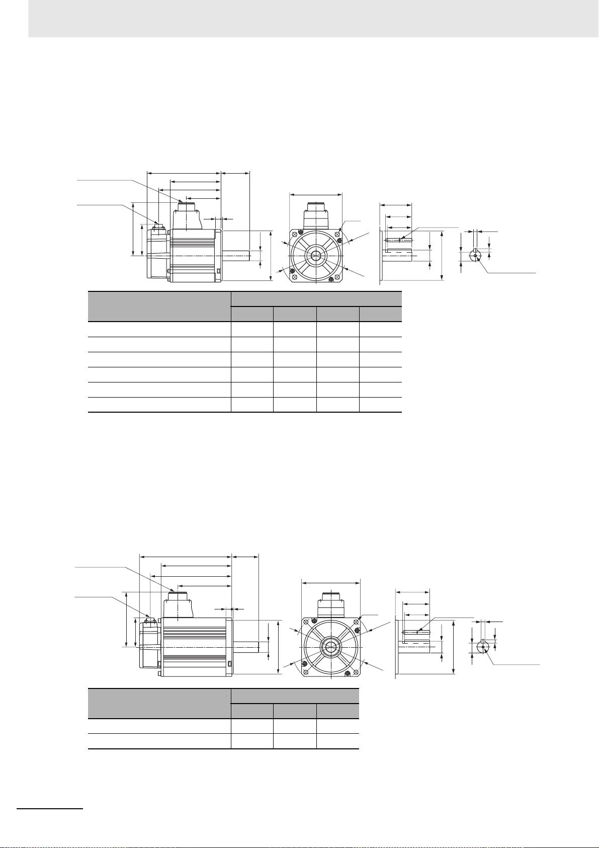
2 Models and External Dimensions
1 kW/1.5 kW/2 kW (without Brake)
R88M-KE1K030H (-S2)/-KE1K530H (-S2)/-KE2K030H (-S2)
1 kW/1.5 kW/2 kW (with Brake)
R88M-KE1K030H-B (S2)/-KE1K530H-B (S2)/-KE2K030H-B (S2)
Motor and brake
connector
Encoder
connector
101
LM
KB2
KB1
84
Model
55LL
100
3
10
ø19h6
ø95h7
(Shaft end specifications with key and tap)
55
4-ø9
ø135
ø115
45
42
M3, through
ø19h6
ø95h7
15.5
6h9
6
M5 depth 12
Dimensions [mm]
LL LM KB1 KB2
R88M-KE1K030 142 97 66 122
R88M-KE1K530 160.5 115.5 84.5 140.5
R88M-KE2K030 179.5 134.5 103.5 159.5
R88M-KE1K030-B 169 124 66 149
R88M-KE1K530-B 187.5 142.5 84.5 167.5
R88M-KE2K030-B 206.5 161.5 103.5 186.5
Note The standard models have a straight shaft. Models with a key and tap are indicated with S2 at the end of the
model number.
Models with an oil seal are indicated with O at the end of the model number. The motor dimensions do not
change.
3 kW (without Brake)
R88M-KE3K030H (-S2)
3 kW (with Brake)
R88M-KE3K030H-B (S2)
Motor and brake
connector
Encoder
LM
KB2
112
connector
113
84
Model
R88M-KE3K030 191 146 171
R88M-KE3K030-B 216 171 196
Note The standard models have a straight shaft. Models with a key and tap are indicated with S2 at the end of the
model number.
Models with an oil seal are indicated with O at the end of the model number. The motor dimensions do not
change.
55LL
120
312
ø22h6
ø110h7
Dimensions [mm]
LL LM KB2
(Shaft end specifications with key and tap)
55
45
4-ø9
ø162
ø145
41
M3, through
ø22h6
ø110h7
18
8h9
7
M5 depth 12
2 - 34
OMNUC G5-series (Pulse-train Input Type) AC Servomotors and Servo Drives User’s Manual
Page 73

4 kW/5 kW (without Brake)
R88M-KE4K030H (-S2)/-KE5K030H (-S2)
4 kW/5 kW (with Brake)
R88M-KE4K030H-B (S2)/-KE5K030H-B (S2)
2 Models and External Dimensions
2-4 External and Mounting Dimensions
Motor and brake
connector
Encoder
connector
118
84
LM
KB2
KB1
Model
65LL
130
612
4-ø9
ø24h6
ø110h7
ø145
Dimensions [mm]
LL LM KB1 KB2
(Shaft end specifications
with key and tap)
65
55
51
M3, through
ø24h6
ø165
ø110h7
20
8h9
7
M8 depth 20
R88M-KE4K030 209 164 127 189
R88M-KE5K030 244 199 162 224
R88M-KE4K030-B 237 192 127 217
R88M-KE5K030-B 272 227 162 252
Note The standard models have a straight shaft. Models with a key and tap are indicated with S2 at the end of the
model number.
Models with an oil seal are indicated with O at the end of the model number. The motor dimensions do not
change.
2
2-4-2 Servomotor Dimensions
OMNUC G5-series (Pulse-train Input Type) AC Servomotors and Servo Drives User’s Manual
2 - 35
Page 74

2 Models and External Dimensions
2,000-r/min Servomotors (200 V)
1 kW/1.5 kW/2 kW/3 kW (without Brake)
R88M-KE1K020H (-S2)/-KE1K520H (-S2)/-KE2K020H (-S2)/-KE3K020H (-S2)
1 kW/1.5 kW/2 kW/3 kW (with Brake)
R88M-KE1K020H-B (S2)/-KE1K520H-B (S2)/-KE2K020H-B (S2)/-KE3K020H-B (S2)
Motor and brake
connector
Encoder
connector
84
116 (1.0 to 2.0 kW)
118 (3.0 kW)
Model
KB2
LM
LRLL
130
KB1
612
øSh6
ø110h7
Dimensions [mm]
LL LR LM S KB1 KB2
(Shaft end specifications with key and tap)
LR
45 (1.0 to 2.0 kW)
55 (3.0 kW)
41 (1.0 to 2.0 kW)
51 (3.0 kW)
4-ø9
ø145
ø165
M3, through
øSh6
ø110h7
18 (1.0 to 2.0 kW)
8h9
20 (3.0 kW)
M5 depth 12 (1.0 to 2.0 kW)
M8 depth 20 (3.0 kW)
R88M-KE1K020 139 55 94 22 60 119
R88M-KE1K520 156.5 55 111.5 22 77.5 136.5
R88M-KE2K020 174 55 129 22 95 154
R88M-KE3K020 209 65 164 24 127 189
R88M-KE1K020-B 167 55 122 22 60 147
R88M-KE1K520-B 184.5 55 139.5 22 77.5 164.5
R88M-KE2K020-B 202 55 157 22 95 182
R88M-KE3K020-B 237 65 192 24 127 217
7
2 - 36
Note The standard models have a straight shaft. Models with a key and tap are indicated with S2 at the end of the
model number.
Models with an oil seal are indicated with O at the end of the model number. The motor dimensions do not
change.
OMNUC G5-series (Pulse-train Input Type) AC Servomotors and Servo Drives User’s Manual
Page 75

4 kW/5 kW (without Brake)
R88M-KE4K020H (-S2)/-KE5K020H (-S2)
4 kW/5 kW (with Brake)
R88M-KE4K020H-B (S2)/-KE5K020H-B (S2)
Motor and brake
connector
Encoder
connector
140
LM
KB2
KB1
84
70LL
3.218
ø35h6
ø114.3h7
2 Models and External Dimensions
(Shaft end specifications
176
with key and tap)
4-ø13.5
ø233
ø200
70
55
50
M3, through
ø35h6
30
ø114.3h7
10h9
8
M12 depth 25
2-4 External and Mounting Dimensions
2
2-4-2 Servomotor Dimensions
Model
LL LM KB1 KB2
Dimensions [mm]
R88M-KE4K020 178 133 96 158
R88M-KE5K020 197 152 115 177
R88M-KE4K020-B 207 162 96 187
R88M-KE5K020-B 226 181 115 206
Note The standard models have a straight shaft. Models with a key and tap are indicated with S2 at the end of the
model number.
Models with an oil seal are indicated with O at the end of the model number. The motor dimensions do not
change.
OMNUC G5-series (Pulse-train Input Type) AC Servomotors and Servo Drives User’s Manual
2 - 37
Page 76
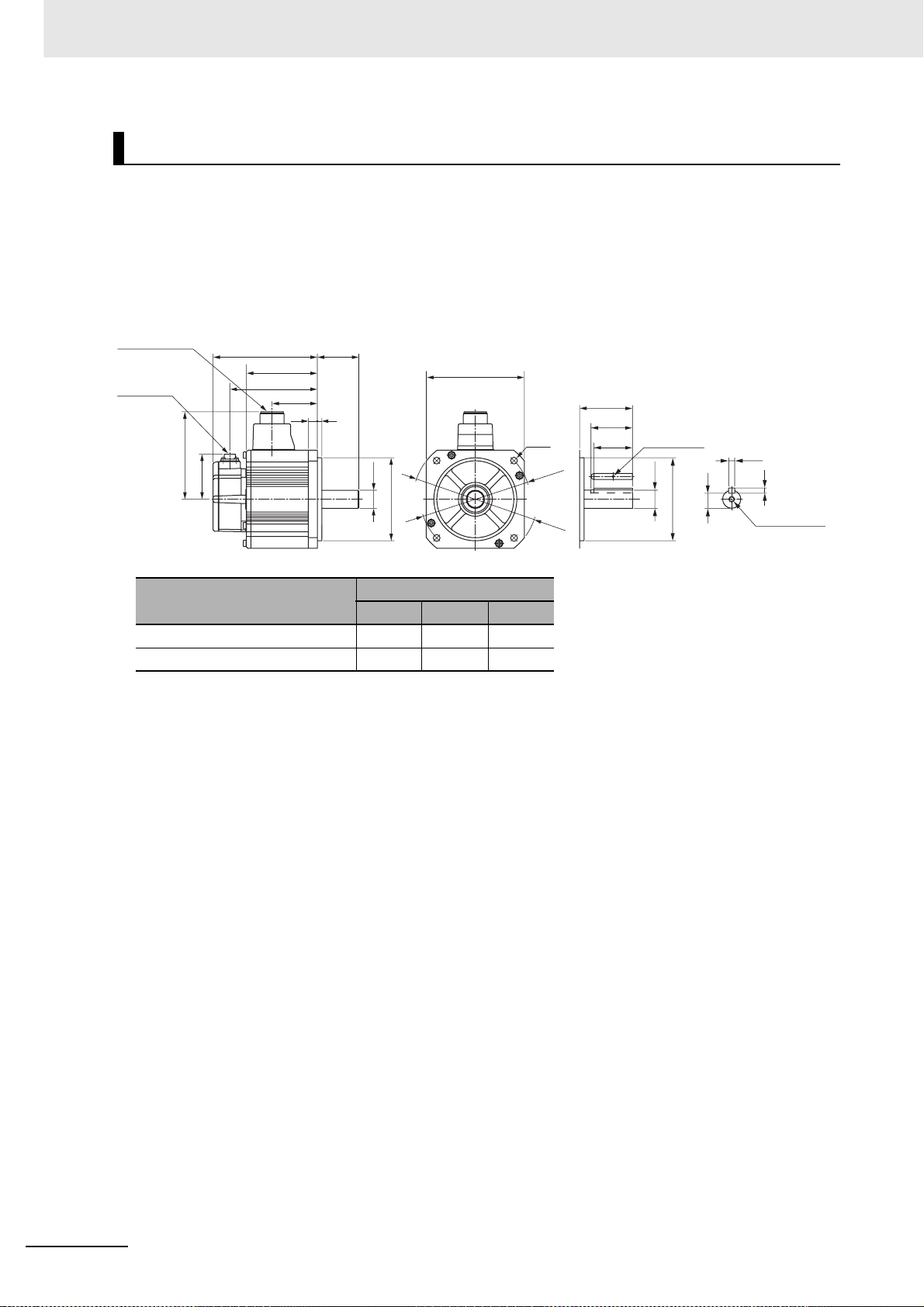
2 Models and External Dimensions
1,000-r/min Servomotors (200 V)
900 W (without Brake)
R88M-KE90010H (-S2)
900 W (with Brake)
R88M-KE90010H-B (S2)
Motor and brake
connector
Encoder
connector
LM
KB2
77.5
116
84
70LL
612
ø22h6
ø110h7
130
4-ø9
(Shaft end specifications with key and tap)
70
45
41
ø145
ø165
M3, through
ø22h6
ø110h7
8h9
18
7
M5 depth 12
Model
Dimensions [mm]
LL LM KB2
R88M-KE90010 156.5 111.5 136.5
R88M-KE90010-B 184.5 139.5 164.5
Note The standard models have a straight shaft. Models with a key and tap are indicated with S2 at the end of the
model number.
Models with an oil seal are indicated with O at the end of the model number. The motor dimensions do not
change.
2 - 38
OMNUC G5-series (Pulse-train Input Type) AC Servomotors and Servo Drives User’s Manual
Page 77

2 kW/3 kW (without Brake)
R88M-KE2K010H (-S2)/-KE3K010H (-S2)
2 kW/3 kW (with Brake)
R88M-KE2K010H-B (S2)/-KE3K010H-B (S2)
Motor and brake
connector
Encoder
connector
140
84
LL
KB2
LM
80
KB1
3.218
ø35h6
ø114.3h7
2 Models and External Dimensions
(Shaft end specifications
176
with key and tap)
4-ø13.5
ø233
ø200
80
55
50
M3, through
ø35h6
30
ø114.3h7
10h9
8
M12 depth 25
2-4 External and Mounting Dimensions
2
2-4-2 Servomotor Dimensions
Model
LL LM KB1 KB2
Dimensions [mm]
R88M-KE2K010 164.5 119.5 82.5 144.5
R88M-KE3K010 210.5 165.5 128.5 190.5
R88M-KE2K010-B 193.5 148.5 82.5 173.5
R88M-KE3K010-B 239.5 194.5 128.5 219.5
Note The standard models have a straight shaft. Models with a key and tap are indicated with S2 at the end of the
model number.
Models with an oil seal are indicated with O at the end of the model number. The motor dimensions do not
change.
OMNUC G5-series (Pulse-train Input Type) AC Servomotors and Servo Drives User’s Manual
2 - 39
Page 78

2 Models and External Dimensions
2-4-3 Combinations of Servomotors and Decelerators
3,000-r/min Servomotors
Servomotor
models
R88MKE05030
R88MKE10030
R88MKE20030
R88MKE40030
R88MKE75030H/T
R88MKE1K030
R88MKE1K530
R88MKE2K030
1/5
R88GHPG11B05100B
(for both with
R88M-KE10030)
R88GHPG11B05100B
R88GHPG14A05200B
R88GHPG14A05400B
R88GHPG20A05750B
R88GHPG32A052K0B
(for both with
R88M-KE2K030)
R88GHPG32A052K0B
(for both with
R88M-KE2K030)
R88GHPG32A052K0B
1/11
(1/9 for flange 11)
R88GHPG11B09050B
(Gear ratio 1/9)
R88GHPG14A11100B
R88GHPG14A11200B
R88GHPG20A11400B
R88GHPG20A11750B
R88GHPG32A112K0B
(for both with
R88M-KE2K030)
R88GHPG32A112K0B
(for both with
R88M-KE2K030)
R88GHPG32A112K0B
1/21 1/33 1/45
R88GHPG14A21100B
(for both with
R88M-KE10030)
R88GHPG14A21100B
R88GHPG20A21200B
R88GHPG20A21400B
R88GHPG32A21750B
R88GHPG32A211K5B
(for both with
R88MKE1K5030)
R88GHPG32A211K5B
R88GHPG50A212K0B
R88GHPG14A33050B
R88GHPG20A33100B
R88GHPG20A33200B
R88GHPG32A33400B
R88GHPG32A33750B
R88GHPG50A332K0B
(for both with
R88M-KE2K030)
R88GHPG50A332K0B
(for both with
R88M-KE2K030)
R88GHPG50A332K0B
R88GHPG14A45050B
R88GHPG20A45100B
R88GHPG20A45200B
R88GHPG32A45400B
R88GHPG32A45750B
R88GHPG50A451K5B
(for both with
R88M-KE1K530)
R88GHPG50A451K5B
–
R88MKE3K030
R88MKE4K030
R88MKE5K030
R88GHPG32A053K0B
R88GHPG32A054K0B
R88GHPG50A055K0B
R88GHPG50A113K0B
R88GHPG50A115K0B
(for both with
R88M-KE5K030)
R88GHPG50A115K0B
R88GHPG50A213K0B
–––
–––
––
2 - 40
OMNUC G5-series (Pulse-train Input Type) AC Servomotors and Servo Drives User’s Manual
Page 79

2,000-r/min Servomotors
2 Models and External Dimensions
2-4 External and Mounting Dimensions
Servomotor
models
R88MKE1K020
R88MKE1K520
R88MKE2K020
R88MKE3K020
R88MKE4K020
R88MKE5K020
1/5 1/11
R88GHPG32A053K0B
(for both with
R88M-KE3K030)
R88GHPG32A053K0B
(for both with
R88M-KE3K030)
R88GHPG32A053K0B
(for both with
R88M-KE3K030
R88GHPG32A054K0B
(for both with
R88M-KE4K030
R88GHPG50A055K0SB
(for both with
R88M-KE5K020
R88GHPG50A055K0SB
)
)
)
R88GHPG32A112K0SB
(for both with
R88M-KE2K020)
R88GHPG32A112K0SB
(for both with
R88M-KE2K020)
R88GHPG32A112K0SB
R88GHPG50A115K0B
(for both with
R88M-KE5K030
R88GHPG50A115K0SB
(for both with
R88M-KE3K030
R88GHPG50A115K0SB
(1/20 for flange 65)
R88G-
HPG32A211K0SB
R88G-
HPG50A213K0B
(for both with
R88M-KE3K030)
R88G-
HPG50A213K0B
(for both with
R88M-KE3K030
R88G-
HPG50A213K0SB
)
R88GHPG65A205K0SB
(for both with
)
R88M-KE3K030
R88G-
HPG65A205K0SB
1/21
(1/25 for flange 65)
R88G-
HPG50A332K0SB
(for both with
R88M-KE2K020)
R88G-
HPG50A332K0SB
(for both with
R88M-KE2K020)
R88G-
HPG50A332K0SB
)
R88G-
HPG65A253K0SB
R88GHPG65A255K0SB
(for both with
)
R88M-KE5K020
R88G-
HPG65A255K0SB
1/33
R88G-
HPG50A451K0SB
)
1/45
–
–
–
–
–
2
2-4-3 Combinations of Servomotors and Decelerators
1,000-r/min Servomotors
Servomotor models 1/5 1/11
R88M-KE90010 R88G-
HPG32A05900TB
R88M-KE2K010 R88G-
HPG32A052K0TB
R88M-KE3K010 R88G-
HPG50A055K0SB
(for both with
R88M-KE5K020)
R88GHPG32A11900TB
R88GHPG50A112K0TB
R88GHPG50A115K0SB
(for both with
R88M-KE5K020)
1/21
(1/20 for flange 65)
R88GHPG50A21900TB
R88GHPG50A212K0TB
(for both with
R88M-KE5K020)
R88GHPG65A205K0SB
(for both with
R88M-KE5K020)
1/33
(1/25 for flange 65)
R88GHPG50A33900TB
R88GHPG65A255K0SB
(for both with
R88M-KE5K020)
R88GHPG65A255K0SB
(for both with
R88M-KE5K020)
OMNUC G5-series (Pulse-train Input Type) AC Servomotors and Servo Drives User’s Manual
2 - 41
Page 80

2 Models and External Dimensions
2-4-4 Decelerator Dimensions
Backlash: 3 Arcminutes max.
For 3,000-r/min Servomotors (50 to 200 W)
Model
50 W 1/5 R88G-HPG11B05100B 1
1/9 R88G-HPG11B09050B 1
1/21 R88G-HPG14A21100B 1
1/33 R88G-HPG14A33050B 1
1/45 R88G-HPG14A45050B 1
100 W 1/5 R88G-HPG11B05100B 1
1/11 R88G-HPG14A11100B 1
1/21 R88G-HPG14A21100B 1
1/33 R88G-HPG20A33100B 2
1/45 R88G-HPG20A45100B 2
200 W 1/5 R88G-HPG14A05200B 1
1/11 R88G-HPG14A11200B 1
1/21 R88G-HPG20A21200B 2
1/33 R88G-HPG20A33200B 2
1/45 R88G-HPG20A45200B 2
Note 1 The standard shaft type is a straight shaft.
2 A model with a key and tap is indicated with J at the end of the model number (the suffix shown in the box). (Example:
R88G-HPG11A05100BJ)
3 The diameter of the motor shaft insertion hole is the same as the shaft diameter of the corresponding Servomotor.
4 For Servomotors with a key, remove the key before use.
Outline
drawing
LM LR C1 C2 D1 D2 D3 D4 D5 E F1 F2
39.5
39.5
64.0
64.0
64.0
39.5
64.0
64.0
66.5
66.5
64.0
64.0
71.0
71.0
71.0
42 40
42 40
58 60
58 60
58 60
42 40
58 60
58 60
80 90
80 90 ø
58 60
58 60
80 90
80 90
80 90
40 46 46 40 39.5 29 27 2.2 15
40 46 46 40 39.5 29 27 2.2 15
60 70 46 56 55.5 40 37 2.5 21
60 70 46 56 55.5 40 37 2.5 21
60 70 46 56 55.5 40 37 2.5 21
40 46 46 40 39.5 29 27 2.2 15
60 70 46 56 55.5 40 37 2.5 21
60 70 46 56 55.5 40 37 2.5 21
ø55 105 46 85 84 59 53 7.5 27
55 105 46 85 84 59 53 7.5 27
60 70 70 56 55.5 40 37 2.5 21
60 70 70 56 55.5 40 37 2.5 21
ø89 105 70 85 84 59 53 7.5 27
ø89 105 70 85 84 59 53 7.5 27
ø89 105 70 85 84 59 53 7.5 27
Dimensions [mm]
Outline drawing 1
C1
φD1
φD4
φD3h7
4-φZ1
Key tap dimensions
QK
h
b
t1
M depth L
φD5
φSh7
E
T
F1
F2LRG
C2
LM
4-Z2Set bolt (AT)
φD2
2 - 42
OMNUC G5-series (Pulse-train Input Type) AC Servomotors and Servo Drives User’s Manual
Page 81
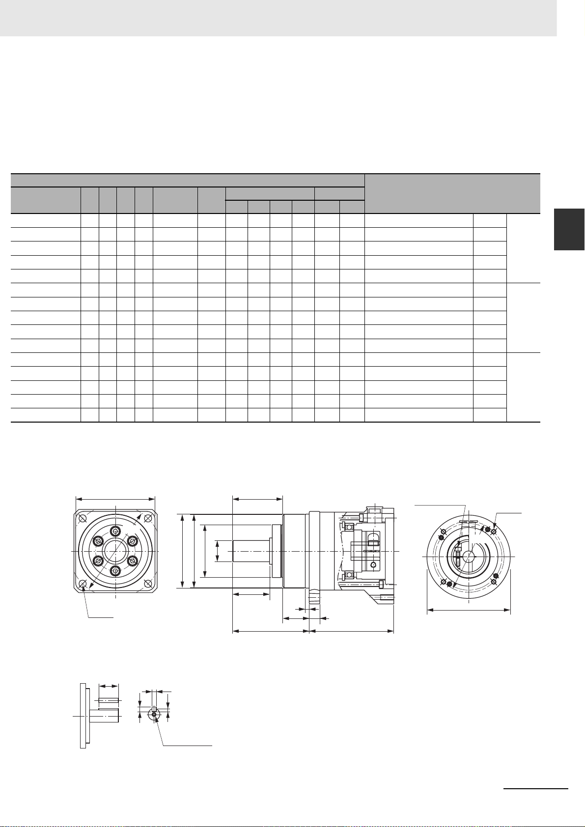
Dimensions [mm]
G S T
5820
5820
81628
81628
81628
5820
81628
81628
10 25 42 9 M4 x 10
10 25 42 9 M4 x 10
81628
81628
10 25 42 9 M4 x 10
10 25 42 9 M4 x 10
10 25 42 9 M4 x 10
Z1
3.4
3.4
5.5
5.5
5.5
3.4
5.5
5.5
5.5
5.5
Z2
M4 x 9
M4 x 9
M4 x 10
M4 x 10
M4 x 10
M4 x 9
M4 x 10
M4 x 10
M4 x 10
M4 x 10
2 Models and External Dimensions
*1
AT
QK b h t1 M L
M3 15 3 3 1.8 M3 6 R88G-HPG11B05100B 1/5 50 W
M3 15 3 3 1.8 M3 6 R88G-HPG11B09050B 1/9
M3 25 5 5 3 M4 8 R88G-HPG14A21100B 1/21
M3 25 5 5 3 M4 8 R88G-HPG14A33050B 1/33
M3 25 5 5 3 M4 8 R88G-HPG14A45050B 1/45
M3 15 3 3 1.8 M3 6 R88G-HPG11B05100B 1/5 100 W
M3 25 5 5 3 M4 8 R88G-HPG14A11100B 1/11
M3 25 5 5 3 M4 8 R88G-HPG14A21100B 1/21
M4 36 8 7 4 M6 12 R88G-HPG20A33100B 1/33
M4 36 8 7 4 M6 12 R88G-HPG20A45100B 1/45
M4 25 5 5 3 M4 8 R88G-HPG14A05200B 1/5 200 W
M4 25 5 5 3 M4 8 R88G-HPG14A11200B 1/11
M4 36 8 7 4 M6 12 R88G-HPG20A21200B 1/21
M4 36 8 7 4 M6 12 R88G-HPG20A33200B 1/33
M4 36 8 7 4 M6 12 R88G-HPG20A45200B 1/45
Key
Tap
Model
2-4 External and Mounting Dimensions
2
2-4-4 Decelerator Dimensions
*1 Indicates set bolt.
Outline drawing 2
C1
φD1
4-φZ1
Key tap dimensions
QK
E
φD5
φD4
φD3h7
b
h
t1
φSh7
T
F1
F2LRG
LM
Set bolt (AT)
4-Z2
φD2
φC2
M depth L
OMNUC G5-series (Pulse-train Input Type) AC Servomotors and Servo Drives User’s Manual
2 - 43
Page 82
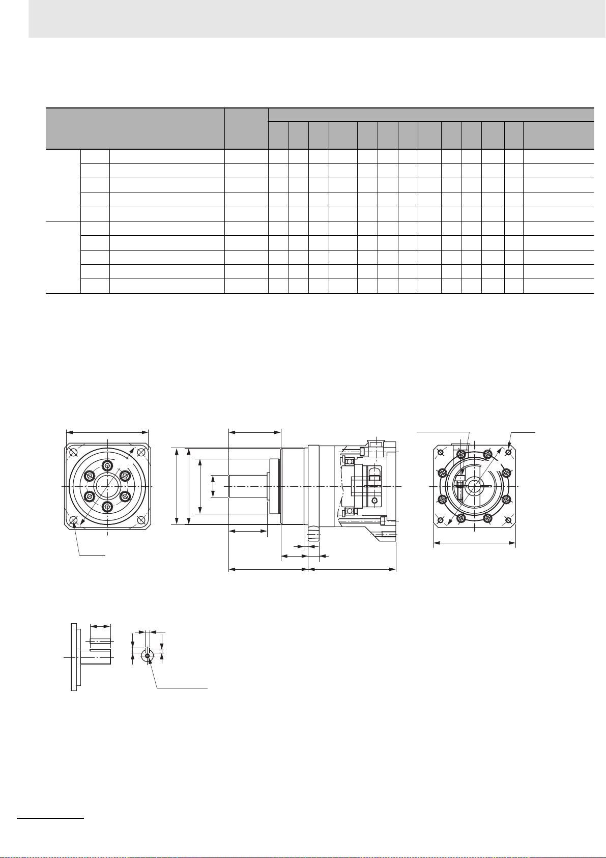
2 Models and External Dimensions
For 3,000-r/min Servomotors (400 to 750 W)
Model
400 W 1/5 R88G-HPG14A05400B 1
1/11 R88G-HPG20A11400B 2
1/21 R88G-HPG20A21400B 2
1/33 R88G-HPG32A33400B 2
1/45 R88G-HPG32A45400B 2
750 W 1/5 R88G-HPG20A05750B 1
1/11 R88G-HPG20A11750B 1
1/21 R88G-HPG32A21750B 2
1/33 R88G-HPG32A33750B 2
1/45 R88G-HPG32A45750B 2
Note 1 The standard shaft type is a straight shaft.
2 A model with a key and tap is indicated with J at the end of the model number (the suffix shown in the box). (Example:
R88G-HPG14A05400BJ)
3 The diameter of the motor shaft insertion hole is the same as the shaft diameter of the corresponding Servomotor.
4 For Servomotors with a key, remove the key before use.
Outline
drawing
LM LR C1 C2 D1 D2 D3 D4 D5 E F1 F2
64 58 6060 70 70 56 55.5 40 37 2.5 21
71 80 90ø89 105 70 85 84 59 53 7.5 27
71 80 90ø89 105 70 85 84 59 53 7.5 27
104 133 120ø122 135 70 115 114 84 98 12.5 35
104 133 120ø122 135 70 115 114 84 98 12.5 35
78 80 9080 105 90 85 84 59 53 7.5 27
78 80 9080 105 90 85 84 59 53 7.5 27
104 133 120ø122 135 90 115 114 84 98 12.5 35
104 133 120ø122 135 90 115 114 84 98 12.5 35
104 133 120ø122 135 90 115 114 84 98 12.5 35
Dimensions [mm]
Outline drawing 1
C1
φD1
4-φZ1
Key tap dimensions
QK
h
b
t1
M depth L
*1
φD4
φD3h7
E
φD5
φSh7
T
*1 The tolerance is “h8” for R88G-HPG50 or R88G-HPG65.
F1
F2LRG
LM
4-Z2Set bolt (AT)
φD2
C2
2 - 44
OMNUC G5-series (Pulse-train Input Type) AC Servomotors and Servo Drives User’s Manual
Page 83

G S T
81628
10 25 42 9 M4 x 10
10 25 42 9 M4 x 10
13 40 82 11 M4 x 10
13 40 82 11 M4 x 10
10 25 42 9 M5 x 12
10 25 42 9 M5 x 12
13 40 82 11 M5 x 12
13 40 82 11 M5 x 12
13 40 82 11 M5 x 12
*1 Indicates set bolt.
Dimensions [mm]
Z1
5.5
Z2
M4 x 10
*1
AT
M4 25 5 5 3
M4 36 8 7 4
M4 36 8 7 4
M4 70 12 8 5
M4 70 12 8 5
M4 36 8 7 4
M4 36 8 7 4
M6 70 12 8 5
M6 70 12 8 5
M6 70 12 8 5
Key
QK
b h t1 M L
2 Models and External Dimensions
Tap
M4
8 R88G-HPG14A05400B 1/5 400 W
M6
12 R88G-HPG20A11400B 1/11
M6
12 R88G-HPG20A21400B 1/21
M10
20 R88G-HPG32A33400B 1/33
M10
20 R88G-HPG32A45400B 1/45
M6
12 R88G-HPG20A05750B 1/5 750 W
M6
12 R88G-HPG20A11750B 1/11
M10
20 R88G-HPG32A21750B 1/21
M10
20 R88G-HPG32A33750B 1/33
M10
20 R88G-HPG32A45750B 1/45
Model
2-4 External and Mounting Dimensions
2
2-4-4 Decelerator Dimensions
Outline drawing 2
C1
φD1
4-φZ1
Key tap dimensions
QK
h
*2
φD3h7
b
t1
M depth L
E
φD5
φD4
φSh7
T
*2 The tolerance is “h8” for R88G-HPG50 or R88G-HPG65.
F1
F2LRG
LM
Set bolt (AT)
4-Z2
φD2
φC2
OMNUC G5-series (Pulse-train Input Type) AC Servomotors and Servo Drives User’s Manual
2 - 45
Page 84

2 Models and External Dimensions
For 3,000-r/min Servomotors (1 to 5 kW)
Model
Outline
drawing
1 kW 1/5 R88G-HPG32A052K0B 2
1/11 R88G-HPG32A112K0B 2
1/21 R88G-HPG32A211K5B 2
1/33 R88G-HPG50A332K0B 2
1/45 R88G-HPG50A451K5B 2
1.5 kW1/5 R88G-HPG32A052K0B 2
1/11 R88G-HPG32A112K0B 2
1/21 R88G-HPG32A211K5B 2
1/33 R88G-HPG50A332K0B 2
1/45 R88G-HPG50A451K5B 2
2 kW 1/5 R88G-HPG32A052K0B 2
1/11 R88G-HPG32A112K0B 2
1/21 R88G-HPG50A212K0B 2
1/33 R88G-HPG50A332K0B 2
3 kW 1/5 R88G-HPG32A053K0B 1
1/11 R88G-HPG50A113K0B 2
1/21 R88G-HPG50A213K0B 2
4 kW 1/5 R88G-HPG32A054K0B 1
1/11 R88G-HPG50A115K0B 1
5 kW 1/5 R88G-HPG50A055K0B 1
1/11 R88G-HPG50A115K0B 1
Dimensions [mm]
LM LR C1 C2 D1 D2 D3 D4 D5 E F1 F2
110 133 120 ø135 135 115 115 114 84 98 12.5 35
110 133 120 ø135 135 115 115 114 84 98 12.5 35
110 133 120 ø135 135 115 115 114 84 98 12.5 35
123 156 170 ø170 190 115 165 163 122 103 12 53
123 156 170 ø170 190 115 165 163 122 103 12 53
110 133 120 ø135 135 115 115 114 84 98 12.5 35
110 133 120 ø135 135 115 115 114 84 98 12.5 35
110 133 120 ø135 135 115 115 114 84 98 12.5 35
123 156 170 ø170 190 115 165 163 122 103 12 53
123 156 170 ø170 190 115 165 163 122 103 12 53
110 133 120 ø135 135 115 115 114 84 98 12.5 35
110 133 120 ø135 135 115 115 114 84 98 12.5 35
123 156 170 ø170 190 115 165 163 122 103 12 53
123 156 170 ø170 190 115 165 163 122 103 12 53
107 133 120 130 135 145 115 114 84 98 12.5 35
123 156 170 ø170 190 145 165 163 122 103 12 53
123 156 170 ø170 190 145 165 163 122 103 12 53
129 133 120 130 135 145 115 114 84 98 12.5 35
149 156 170 130 190 145 165 163 122 103 12 53
149 156 170 130 190 145 165 163 122 103 12 53
149 156 170 130 190 145 165 163 122 103 12 53
Note 1 The standard shaft type is a straight shaft.
2 A model with a key and tap is indicated with J at the end of the model number (the suffix shown in the box). (Example:
R88G-HPG32A052K0BJ)
3 The diameter of the motor shaft insertion hole is the same as the shaft diameter of the corresponding Servomotor.
4 For Servomotors with a key, remove the key before use.
Outline drawing 1
C1
φD1
4-φZ1
Key tap dimensions
QK
b
h
t1
*1
φD4
φD3h7
E
φD5
φSh7
LR
F1
F2
G
LM
T
*1 The tolerance is “h8” for R88G-HPG50 or R88G-HPG65.
Set bolt (AT)
φD2
C2
4-Z2
2 - 46
M depth L
OMNUC G5-series (Pulse-train Input Type) AC Servomotors and Servo Drives User’s Manual
Page 85

Dimensions [mm]
G S T
13 40 82 11 M8 x 10
13 40 82 11 M8 x 10
13 40 82 11 M8 x 10
16 50 82 14 M8 x 10
16 50 82 14 M8 x 10
13 40 82 11 M8 x 10
13 40 82 11 M8 x 10
13 40 82 11 M8 x 10
16 50 82 14 M8 x 10
16 50 82 14 M8 x 10
13 40 82 11 M8 x 10
13 40 82 11 M8 x 10
16 50 82 14 M8 x 10
16 50 82 14 M8 x 10
13 40 82 11 M8 x 18
16 50 82 14 M8 x 16
16 50 82 14 M8 x 16
13 40 82 11 M8 x 25
16 50 82 14 M8 x 25
16 50 82 14 M8 x 25
16 50 82 14 M8 x 25
Z1
Z2
*1
AT
M6 70 12 8
M6 70 12 8
M6 70 12 8
M6 70 14 9
M6 70 14 9
M6 70 12 8
M6 70 12 8
M6 70 12 8
M6 70 14 9
M6 70 14 9
M6 70 12 8
M6 70 12 8
M6 70 14 9
M6 70 14 9
M6 70 12 8
M6 70 14 9
M6 70 14 9
M6 70 12 8
M6 70 14 9
M6 70 14 9
M6 70 14 9
Key
QK
b h t1 M L
5
5
5
5.5
5.5
5
5
5
5.5
5.5
5
5
5.5
5.5
5
5.5
5.5
5
5.5
5.5
5.5
M10
M10
M10
M10
M10
M10
M10
M10
M10
M10
M10
M10
M10
M10
M10
M10
M10
M10
M10
M10
M10
2 Models and External Dimensions
Tap
20
R88G-HPG32A052K0B 1/5 1 kW
20
R88G-HPG32A112K0B 1/11
20
R88G-HPG32A211K5B 1/21
20
R88G-HPG50A332K0B 1/33
20
R88G-HPG50A451K5B 1/45
20
R88G-HPG32A052K0B 1/5 1.5 kW
20
R88G-HPG32A112K0B 1/11
20
R88G-HPG32A211K5B 1/21
20
R88G-HPG50A332K0B 1/33
20
R88G-HPG50A451K5B 1/45
20
R88G-HPG32A052K0B 1/5 2 kW
20
R88G-HPG32A112K0B 1/11
20
R88G-HPG50A212K0B 1/21
20
R88G-HPG50A332K0B 1/33
20
R88G-HPG32A053K0B 1/5 3 kW
20
R88G-HPG50A113K0B 1/11
20
R88G-HPG50A213K0B 1/21
20
R88G-HPG32A054K0B 1/5 4 kW
20
R88G-HPG50A115K0B 1/11
20
R88G-HPG50A055K0B 1/5 5 kW
20
R88G-HPG50A115K0B 1/11
Model
2-4 External and Mounting Dimensions
2
2-4-4 Decelerator Dimensions
*1 Indicates set bolt.
Outline drawing 2
C1
φD1
4-φZ1
Key tap dimensions
QK
E
*2
φD5
φD4
φD3h7
b
h
t1
φSh7
LR
F1
F2
G
LM
T
*2 The tolerance is “h8” for R88G-HPG50 or R88G-HPG65.
Set bolt (AT)
4-Z2
φD2
φC2
M depth L
OMNUC G5-series (Pulse-train Input Type) AC Servomotors and Servo Drives User’s Manual
2 - 47
Page 86

2 Models and External Dimensions
For 2,000-r/min Servomotors (1 kW)
Model
1 kW 1/5 R88G-HPG32A053K0B 1
1/11 R88G-HPG32A112K0SB 1
1/21 R88G-HPG32A211K0SB 1
1/33 R88G-HPG50A332K0SB 2
1/45 R88G-HPG50A451K0SB 2
Note 1 The standard shaft type is a straight shaft.
2 A model with a key and tap is indicated with J at the end of the model number (the suffix shown in the box). (Example:
R88G-HPG32A053K0BJ)
3 The diameter of the motor shaft insertion hole is the same as the shaft diameter of the corresponding Servomotor.
4 For Servomotors with a key, remove the key before use.
Outline
drawing
LM LR
107 133 120
107 133 120
107 133 120
123 156 170 ø
123 156 170 ø
C1 C2 D1 D2 D3 D4 D5 E F1 F2
130
130
130
170
170
Dimensions [mm]
135 145 115 114 84 98 12.5
135 145 115 114 84 98 12.5
135 145 115 114 84 98 12.5
190 145 165 163 122 103 12
190 145 165 163 122 103 12
Outline drawing 1
C1
φD1
E
Set bolt (AT)
φD2
35
35
35
53
53
4-Z2
4-φZ1
Key tap dimensions
QK
h
b
t1
M depth L
φD3
φD4
φD5
φSh7
LR
F1
F2
C2
G
LM
T
2 - 48
OMNUC G5-series (Pulse-train Input Type) AC Servomotors and Servo Drives User’s Manual
Page 87

Dimensions [mm]
G S T
13 40 82 11 M8 x 18
13 40 82 11 M8 x 18
13 40 82 11 M8 x 18
16 50 82 14 M8 x 16
16 50 82 14 M8 x 16
Z1
Z2
*1
AT
M6 70 12 8
M6 70 12 8
M6 70 12 8
M6 70 14 9
M6 70 14 9
Key
QK
b h t1 M L
2 Models and External Dimensions
Tap
5
M10 20 R88G-HPG32A053K0B
5
M10 20 R88G-HPG32A112K0SB
5
M10 20 R88G-HPG32A211K0SB
5.5
M10 20 R88G-HPG50A332K0SB
5.5
M10 20 R88G-HPG50A451K0SB
2-4 External and Mounting Dimensions
Model
1/5 1 kW
1/11
1/21
1/33
1/45
*1 Indicates set bolt.
Outline drawing 2
C1
φD1
4-φZ1
Key tap dimensions
QK
2
2-4-4 Decelerator Dimensions
E
*1
φD5
φD4
φD3h7
b
h
t1
φSh7
LR
F1
F2
G
LM
T
*1 The tolerance is “h8” for R88G-HPG50 or R88G-HPG65.
Set bolt (AT)
4-Z2
φD2
φC2
M depth L
OMNUC G5-series (Pulse-train Input Type) AC Servomotors and Servo Drives User’s Manual
2 - 49
Page 88

2 Models and External Dimensions
For 2,000-r/min Servomotors (1.5 to 5 kW)
Model
1.5kW1/5 R88G-HPG32A053K0B 1
1/11 R88G-HPG32A112K0SB 1
1/21 R88G-HPG50A213K0B 2
1/33 R88G-HPG50A332K0SB 2
2 kW 1/5 R88G-HPG32A053K0B 1
1/11 R88G-HPG32A112K0SB 1
1/21 R88G-HPG50A213K0B 2
1/33 R88G-HPG50A332K0SB 2
3 kW 1/5 R88G-HPG32A054K0B 1
1/11 R88G-HPG50A115K0B 1
1/21 R88G-HPG50A213K0SB 1
1/25 R88G-HPG65A253K0SB 1
4 kW 1/5 R88G-HPG50A055K0SB 1
1/11 R88G-HPG50A115K0SB 1
1/20 R88G-HPG65A205K0SB 1
1/25 R88G-HPG65A255K0SB 1
5 kW 1/5 R88G-HPG50A055K0SB 1
1/11 R88G-HPG50A115K0SB 1
1/20 R88G-HPG65A205K0SB 1
1/25 R88G-HPG65A255K0SB 1
Outline
drawing
Dimensions [mm]
LM LR
107 133 120 130 135 145 115 114 84
107 133 120 130 135 145 115 114 84
123 156 170 ø170 190 145 165 163 122
123 156 170 ø170 190 145 165 163 122
107 133 120 130 135 145 115 114 84
107 133 120 130 135 145 115 114 84
123 156 170 ø170 190 145 165 163 122
123 156 170 ø170 190 145 165 163 122
129 133 120 130 135 145 115 114 84
149 156 170 130 190 145 165 163 122
149 156 170130 190 145 165 163 122
231 222 230 130 260 145 220 214 168
149 156 170 180 190 200 165 163 122
149 156 170180 190 200 165 163 122
231 222 230 180 260 200 220 214 168
231 222 230 180 260 200 220 214 168
149 156 170 180 190 200 165 163 122
149 156 170180 190 200 165 163 122
231 222 230 180 260 200 220 214 168
231 222 230 180 260 200 220 214 168
C1 C2 D1 D2 D3 D4 D5 E F1 F2
98 12.5 35
98 12.5 35
103 12 53
103 12 53
98 12.5 35
98 12.5 35
103 12 53
103 12 53
98 12.5 35
103 12 53
103 12 53
165 12 57
103 12 53
103 12 53
165 12 57
165 12 57
103 12 53
103 12 53
165 12 57
165 12 57
Note 1 The standard shaft type is a straight shaft.
2 A model with a key and tap is indicated with J at the end of the model number (the suffix shown in the box). (Example:
R88G-HPG32A053K0BJ)
3 The diameter of the motor shaft insertion hole is the same as the shaft diameter of the corresponding Servomotor.
4 For Servomotors with a key, remove the key before use.
Outline drawing 1
C1
φD1
4-φZ1
Key tap dimensions
QK
b
h
t1
*1
φD4
φD3h7
E
φD5
φSh7
LR
F1
F2
G
LM
T
*1 The tolerance is “h8” for R88G-HPG50 or R88G-HPG65.
Set bolt (AT)
φD2
C2
4-Z2
2 - 50
M depth L
OMNUC G5-series (Pulse-train Input Type) AC Servomotors and Servo Drives User’s Manual
Page 89

Dimensions [mm]
G S T
13 40 82 11 M8 x 18
13 40 82 11 M8 x 18
16 50 82 14 M8 x 16
16 50 82 14 M8 x 16
13 40 82 11 M8 x 18
13 40 82 11 M8 x 18
16 50 82 14 M8 x 16
16 50 82 14 M8 x 16
13 40 82 11 M8 x 25
16 50 82 14 M8 x 25
16 50 82 14 M8 x 25
25 80 130 18 M8 x 25
16 50 82 14 M12 x 25
16 50 82 14 M12 x 25
25 80 130 18 M12 x 25
25 80 130 18 M12 x 25
16 50 82 14 M12 x 25
16 50 82 14 M12 x 25
25 80 130 18 M12 x 25
25 80 130 18 M12 x 25
Z1
Z2
70
70
70
70
70
70
70
70
70
70
70
70
70
70
70
Key
12
85M10
12
85M10
14
95.5M10
14
95.5M10
12
85M10
12
85M10
14
95.5M10
14
95.5M10
12
85M10
14
95.5M10
14
95.5M10
22
14 9 M16
14
95.5M10
14
95.5M10
22
14 9 M16
22
14 9 M16
14
95.5M10
14
95.5M10
22
14 9 M16
22
14 9 M16
*1
AT
QK b h t1 M L
M6
M6
M6
M6
M6
M6
M6
M6
M6
M6
M6
M8
110
M6
M6
M8
110
M8
110
M6
M6
M8
110
M8
110
2 Models and External Dimensions
Tap
20 R88G-HPG32A053K0B 1/5 1.5
20 R88G-HPG32A112K0SB 1/11
20 R88G-HPG50A213K0B 1/21
20 R88G-HPG50A332K0SB 1/33
20 R88G-HPG32A053K0B 1/5 2 kW
20 R88G-HPG32A112K0SB 1/11
20 R88G-HPG50A213K0B 1/21
20 R88G-HPG50A332K0SB 1/33
20 R88G-HPG32A054K0B 1/5 3 kW
20 R88G-HPG50A115K0B 1/11
20 R88G-HPG50A213K0SB 1/21
35 R88G-HPG65A253K0SB 1/25
20 R88G-HPG50A055K0SB 1/5 4 kW
20 R88G-HPG50A115K0SB 1/11
35 R88G-HPG65A205K0SB 1/20
35 R88G-HPG65A255K0SB 1/25
20 R88G-HPG50A055K0SB 1/5 5 kW
20 R88G-HPG50A115K0SB 1/11
35 R88G-HPG65A205K0SB 1/20
35 R88G-HPG65A255K0SB 1/25
Model
2-4 External and Mounting Dimensions
kW
2
2-4-4 Decelerator Dimensions
*1 Indicates set bolt.
Outline drawing 2
C1
φD1
4-φZ1
Key tap dimensions
QK
E
*2
φD5
φD4
φD3h7
b
h
t1
φSh7
LR
F1
F2
G
LM
T
*2 The tolerance is “h8” for R88G-HPG50 or R88G-HPG65.
Set bolt (AT)
4-Z2
φD2
φC2
M depth L
OMNUC G5-series (Pulse-train Input Type) AC Servomotors and Servo Drives User’s Manual
2 - 51
Page 90

2 Models and External Dimensions
For 1,000-r/min Servomotors (900 W to 3 kW)
Model
900 W
Note 1 The standard shaft type is a straight shaft.
1/5
R88G-HPG32A05900TB 1
1/11
R88G-HPG32A11900TB 1
1/21
R88G-HPG50A21900TB 1
1/33
R88G-HPG50A33900TB 1
2 kW
1/5
R88G-HPG32A052K0TB 1
1/11
R88G-HPG50A112K0TB 1
1/21
R88G-HPG50A212K0TB 1
1/25
R88G-HPG65A255K0SB 1
3 kW
1/5
R88G-HPG50A055K0SB 1
1/11
R88G-HPG50A115K0SB 1
1/20
R88G-HPG65A205K0SB 1
1/25
R88G-HPG65A255K0SB 1
2 A model with a key and tap is indicated with J at the end of the model number (the suffix shown in the box). (Example:
R88G-HPG32A05900TBJ)
3 The diameter of the motor shaft insertion hole is the same as the shaft diameter of the corresponding Servomotor.
4 For Servomotors with a key, remove the key before use.
Outline
drawing
LM
LR C1 C2 D1 D2 D3 D4 D5 E F1
129 133 120 130 135 145 115 114 84 98
129 133 120 130 135 145 115 114 84 98
149 156 170 130 190 145 165 163 122 103
149 156 170 130 190 145 165 163 122 103
129 133 120 180 135 200 115 114 84 98
149 156 170 180 190 200 165 163 122 103
231 222 230180 260 200 220 214 168 165
231 222 230 180 260 200 220 214 168 165
149 156 170 180 190 200 165 163 122 103
149 156 170180 190 200 165 163 122 103
231 222 230 180 260 200 220 214 168 165
231 222 230 180 260 200 220 214 168 165
Dimensions [mm]
12.5
12.5
12
12
12.5
12
12
12
12
12
12
12
F2
35
35
53
53
35
53
53
57
53
53
57
57
Outline drawing 1
C1
φD1
4-φZ1
Key tap dimensions
QK
*1
φD4
φD3h7
b
h
t1
E
φD5
φSh7
T
*1 The tolerance is “h8” for R88G-HPG50 or R88G-HPG65.
F1
F2LRG
LM
Set bolt (AT)
4-Z2
φD2
C2
2 - 52
M depth L
OMNUC G5-series (Pulse-train Input Type) AC Servomotors and Servo Drives User’s Manual
Page 91
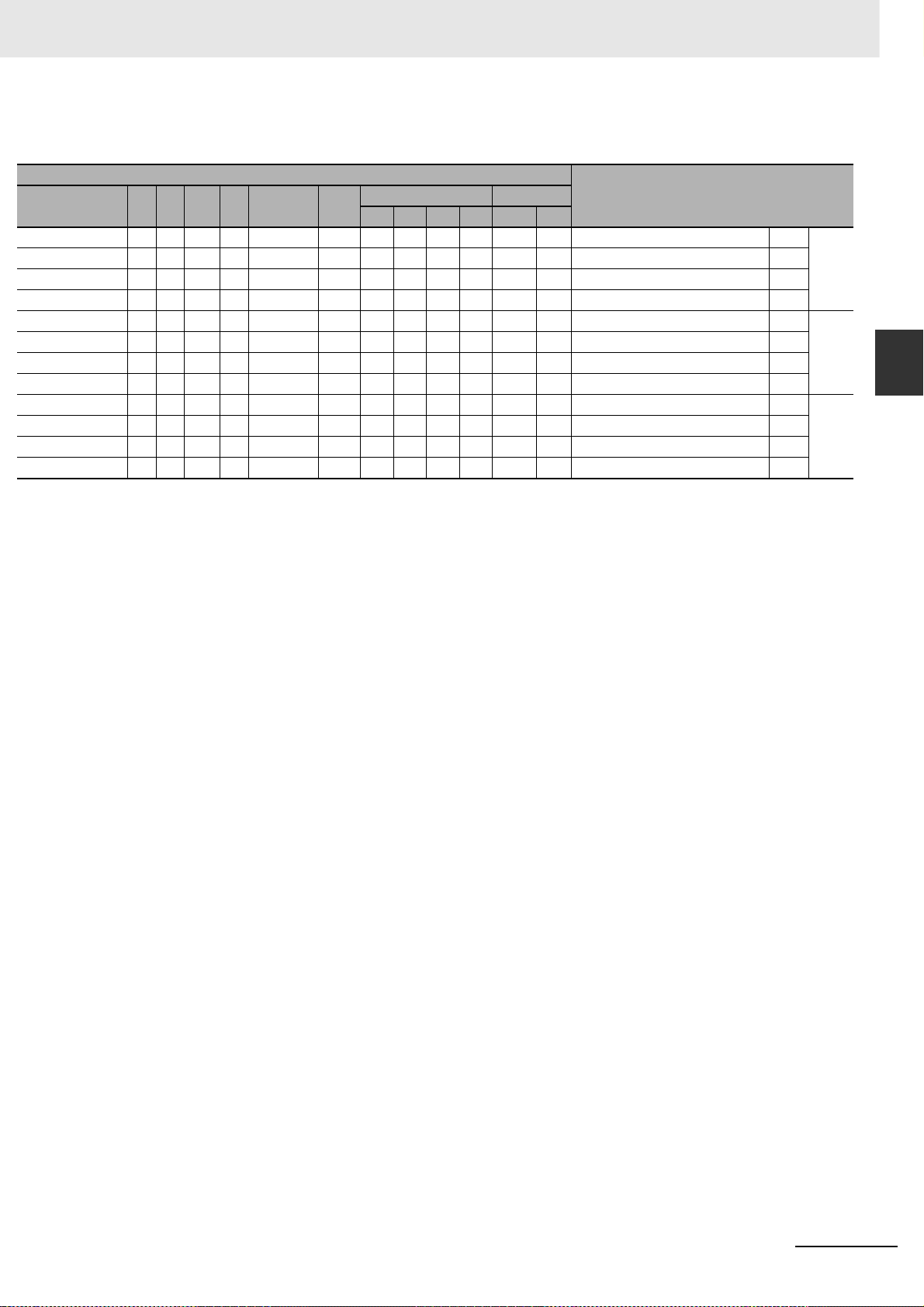
G S T
13 40
13 40
16 50
16 50
13 40
16 50
25 80
25 80
16 50
16 50
25 80
25 80
Dimensions [mm]
Z1
82
11
82
11
82
14
82
14
82
11
82
14
130
18
130
18
82
14
82
14
130
18
130
18
Z2
M8 x 25
M8 x 25
M8 x 25
M8 x 25
M12 x 25
M12 x 25
M12 x 25
M12 x 25
M12 x 25
M12 x 25
M12 x 25
M12 x 25
AT
M6
M6
M6
M6
M6
M6
M8
M8
M6
M6
M8
M8
2 Models and External Dimensions
2-4 External and Mounting Dimensions
*1
QK
110
110
110
110
Key
b h t1 M L
70
70
70
70
70
70
70
70
12 8
12 8
14 9
14 9
12 8
14 9
22 14
22 14
14 9
14 9
22 14
22 14
5
5
5.5
5.5
5
5.5
9
9
5.5
5.5
9
9
Tap
M10 20 R88G-HPG32A05900TB
M10 20 R88G-HPG32A11900TB
M10 20 R88G-HPG50A21900TB
M10 20 R88G-HPG50A33900TB
M10 20 R88G-HPG32A052K0TB
M10 20 R88G-HPG50A112K0TB
M16 35 R88G-HPG50A212K0TB
M16 35 R88G-HPG65A255K0SB
M10 20 R88G-HPG50A055K0SB
M10 20 R88G-HPG50A115K0SB
M16 35 R88G-HPG65A205K0SB
M16 35 R88G-HPG65A255K0SB
Model
1/5
1/11
1/21
1/33
1/5
1/11
1/21
1/25
1/5
1/11
1/20
1/25
900 W
2 kW
3 kW
2
2-4-4 Decelerator Dimensions
*1 Indicates set bolt.
OMNUC G5-series (Pulse-train Input Type) AC Servomotors and Servo Drives User’s Manual
2 - 53
Page 92
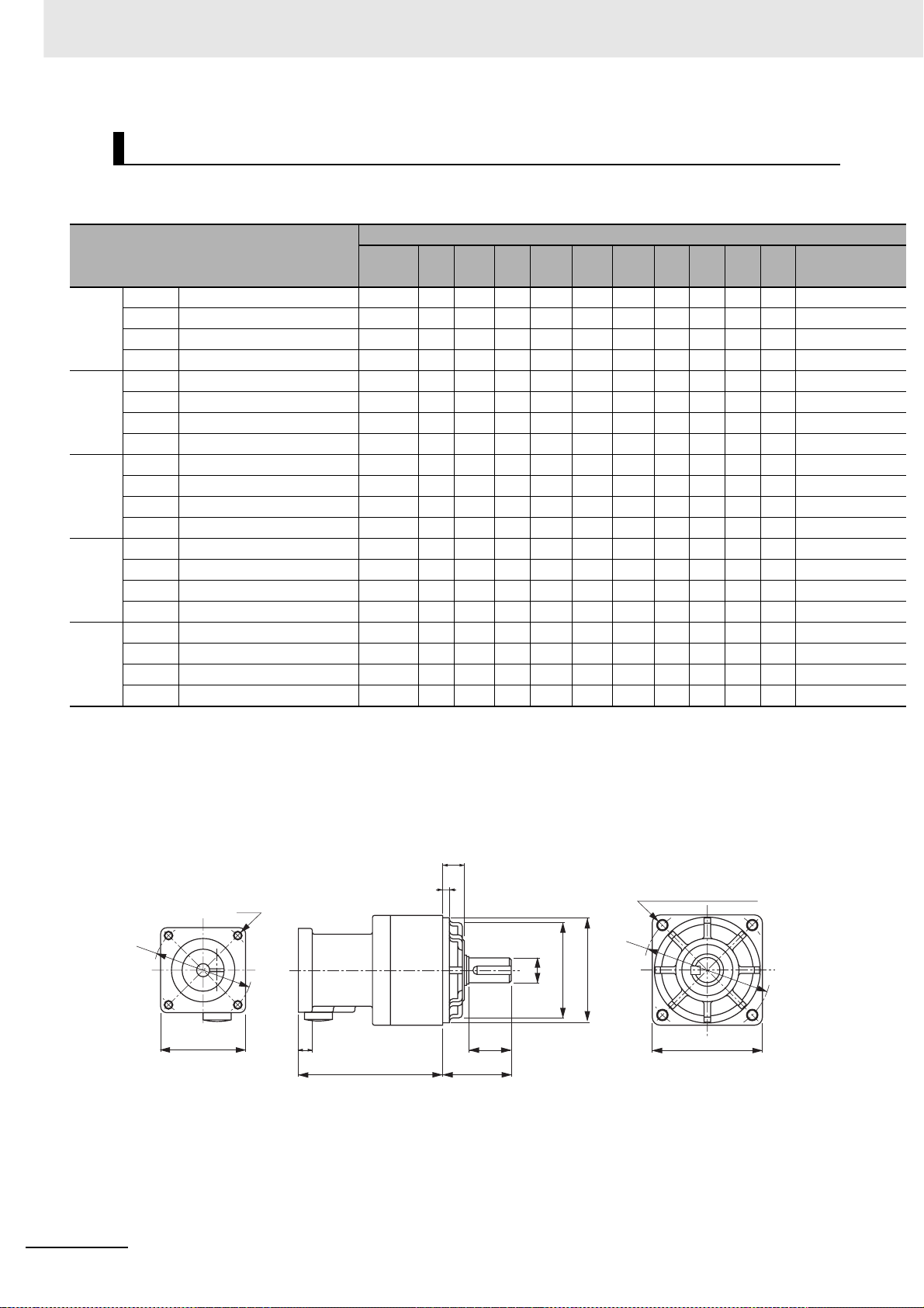
2 Models and External Dimensions
Backlash: 15 Arcminutes max.
For 3,000-r/min Servomotors
Dimensions [mm]
Model
50 W 1/5 R88G-VRSF05B100CJ 67.5 32 40 52 46 60 50 45 10 3 6
1/9 R88G-VRSF09B100CJ 67.5 32 40 52 46 60 50 45 10 3 6
1/15 R88G-VRSF15B100CJ 78.0 32 40 52 46 60 50 45 10 3 6
1/25 R88G-VRSF25B100CJ 78.0 32 40 52 46 60 50 45 10 3 6
100 W 1/5 R88G-VRSF05B100 CJ 67.5 32 40 52 46 60 50 45 1 0 3 6
1/9 R88G-VRSF09B100CJ 67.5 32 40 52 46 60 50 45 10 3 6
1/15 R88G-VRSF15B100CJ 78.0 32 40 52 46 60 50 45 10 3 6
1/25 R88G-VRSF25B100CJ 78.0 32 40 52 46 60 50 45 10 3 6
200 W 1/5 R88G-VRSF05B200 CJ 72.5 32 60 52 70 60 50 45 1 0 3 10
1/9 R88G-VRSF09C200CJ 89.5 50 60 78 70 90 70 62 17 3 8
1/15 R88G-VRSF15C200CJ 100.0 50 60 78 70 90 70 62 17 3 8
1/25 R88G-VRSF25C200CJ 100.0 50 60 78 70 90 70 62 17 3 8
400 W 1/5 R88G-VRSF05C400CJ 89.5 50 60 78 70 90 70 62 17 3 8
1/9 R88G-VRSF09C400CJ 89.5 50 60 78 70 90 70 62 17 3 8
1/15 R88G-VRSF15C400CJ 100.0 50 60 78 70 90 70 62 17 3 8
1/25 R88G-VRSF25C400CJ 100.0 50 60 78 70 90 70 62 17 3 8
750 W 1/5 R88G-VRSF05C750CJ 93.5 50 80 78 90 90 70 62 17 3 10
1/9 R88G-VRSF09D750CJ 97.5 61 80 98 90 115 90 75 18 5 10
1/15 R88G-VRSF15D750CJ 110.0 61 80 98 90 115 90 75 18 5 10
1/25 R88G-VRSF25D750CJ 110.0 61 80 98 90 115 90 75 18 5 10
LM LR C1 C2 D1 D2 D3 D4 E3 F G
Note 1 The standard shaft type is a shaft with key.
2 The diameter of the motor shaft insertion hole is the same as the shaft diameter of the corresponding Servomotor.
3 For Servomotors with a key, remove the key before use.
Outline drawing
E3
φD1
C1
4-Z1
F
G T
LM
LR
φSh6
φD4
φD3h7
4-Z2 (available depth L)
φD2
C2
2 - 54
OMNUC G5-series (Pulse-train Input Type) AC Servomotors and Servo Drives User’s Manual
Page 93

2 Models and External Dimensions
Dimensions [mm]
S T Z1 Z2
AT
*1
L
QK b h t1
Key
12 20 M4 M5 M3 12 16 4 4 2.5 R88G-VRSF05B100CJ 1/5 50 W
12 20 M4 M5 M3 12 16 4 4 2.5 R88G-VRSF09B100CJ 1/9
12 20 M4 M5 M3 12 16 4 4 2.5 R88G-VRSF15B100CJ 1/15
12 20 M4 M5 M3 12 16 4 4 2.5 R88G-VRSF25B100CJ 1/25
12 20 M4 M5 M3 12 16 4 4 2.5 R88G-VRSF05B100CJ 1/5 100 W
12 20 M4 M5 M3 12 16 4 4 2.5 R88G-VRSF09B100CJ 1/9
12 20 M4 M5 M3 12 16 4 4 2.5 R88G-VRSF15B100CJ 1/15
12 20 M4 M5 M3 12 16 4 4 2.5 R88G-VRSF25B100CJ 1/25
12 20 M4 M5 M4 12 16 4 4 2.5 R88G-VRSF05B200CJ 1/5 200 W
19 30 M4 M6 M4 20 22 6 6 3.5 R88G-VRSF09C200CJ 1/9
19 30 M4 M6 M4 20 22 6 6 3.5 R88G-VRSF15C200CJ 1/15
19 30 M4 M6 M4 20 22 6 6 3.5 R88G-VRSF25C200CJ 1/25
19 30 M4 M6 M4 20 22 6 6 3.5 R88G-VRSF05C400CJ 1/5 400 W
19 30 M4 M6 M4 20 22 6 6 3.5 R88G-VRSF09C400CJ 1/9
19 30 M4 M6 M4 20 22 6 6 3.5 R88G-VRSF15C400CJ 1/15
19 30 M4 M6 M4 20 22 6 6 3.5 R88G-VRSF25C400CJ 1/25
19 30 M5 M6 M4 20 22 6 6 3.5 R88G-VRSF05C750CJ 1/5 750 W
24 40 M5 M8 M4 20 30 8 7 4 R88G-VRSF09D750CJ 1/9
24 40 M5 M8 M4 20 30 8 7 4 R88G-VRSF15D750CJ 1/15
24 40 M5 M8 M4 20 30 8 7 4 R88G-VRSF25D750CJ 1/25
Model
2-4 External and Mounting Dimensions
2
2-4-4 Decelerator Dimensions
*1 Indicates set bolt.
Outline drawing
Set bolt (AT)
Key dimensions
QK
b
t1
h
OMNUC G5-series (Pulse-train Input Type) AC Servomotors and Servo Drives User’s Manual
2 - 55
Page 94

2 Models and External Dimensions
2-4-5 External Regeneration Resistor Dimensions
R88A-RR08050S/-RR080100S
Thermal switch output
)
2
)
2
φ3
500
(0.75 mm
(0.3 mm
φ1.5
6
1.2 104
20
R88A-RR22047S/-RR22047S1
Thermal switch output
)
2
)
2
φ3
500
(0.75 mm
(0.3 mm
φ1.5
6
1.2 200
20
122
130
220
4.2
4.2
28
48
43.5
62
R88A-RR50020S
43 2510
78
230
360
386
402
5.2
40
76
2 - 56
OMNUC G5-series (Pulse-train Input Type) AC Servomotors and Servo Drives User’s Manual
Page 95

2-4-6 Reactor Dimensions
3G3AX-DL2002
72
2 Models and External Dimensions
2-4 External and Mounting Dimensions
90
Ground terminal (M4)
3G3AX-DL2004
56
66
2-M4
4-5.2 × 8
98
72
90
2
2-4-6 Reactor Dimensions
85
2-M4
Ground terminal (M4)
56
66
OMNUC G5-series (Pulse-train Input Type) AC Servomotors and Servo Drives User’s Manual
4-5.2 × 8
95
98
2 - 57
Page 96

2 Models and External Dimensions
3G3AX-DL2007
Ground terminal (M4)
72
90
2-M4
3G3AX-DL2015
Ground terminal (M4)
56
66
4-5.2 × 8
98
72
90
2-M4
105
2 - 58
56
66
OMNUC G5-series (Pulse-train Input Type) AC Servomotors and Servo Drives User’s Manual
4-5.2 × 8
98
115
Page 97

3G3AX-DL2022
Ground terminal (M4)
80
2 Models and External Dimensions
2-4 External and Mounting Dimensions
100
2-M4
71
86
3G3AX-AL2025/-AL2055
Terminal screw 6-K
Terminal block
Ro R So S To
T
4-6 × 9
116
Ground terminal (M5)
105
ED
2
2-4-6 Reactor Dimensions
H
H1
X±1
A
Model
3G3AX-AL2025 130 82 60 40 150 92 50 67 M4 9.5
3G3AX-AL2055 140 98 60 40 150 92 50 75 M4 9.5
A C D E H H1 X Y K W
4-φ6
(Cutout)
Dimensions [mm]
Y±1
C
W
Ro R So S To T
Connection Diagram
OMNUC G5-series (Pulse-train Input Type) AC Servomotors and Servo Drives User’s Manual
2 - 59
Page 98

2 Models and External Dimensions
3G3AX-AL2110
Terminal hole 6-φK
A
Ro R So S To T
H
4-φ6
(Cutout)
Ground terminal (M6)
Model
3G3AX-AL2110 160 103 70 170 106 60 80 5.3 12
A C D H H1 X Y K W
Dimensions [mm]
55D
H1
Y±1X±1
C
Ro R So S To T
Connection Diagram
W
W= Terminal width
2 - 60
OMNUC G5-series (Pulse-train Input Type) AC Servomotors and Servo Drives User’s Manual
Page 99

2 Models and External Dimensions
2-4-7 Mounting Bracket (L-brackets for Rack Mounting) Dimensions
R88A-TK01K
BottomTop
2-4 External and Mounting Dimensions
2-C5
17
9.5
24
R2
ø5.2
15
10
7
40
R88A-TK02K
2-C5
17
9.5
24
R2
ø5.2
15
10
7
2-M4 countersunk
11±0.2
R
2-M4 countersunk
18±0.2
47
11±0.2
5
2-R1
33
40
2-M4 countersunk
5.2
R2
2.5
R1 max.
2.5
2
2-4-7 Mounting Bracket (L-brackets for Rack Mounting) Dimensions
2-C5
17
9.5
2.5
2
R1 max.
2.5
R2
15
10
BottomTop
5
18±0.2
2-M4 countersunk
5.2
2-R1
40
47
R2
2.5
R1 max.
2.5
R2
2.5
R1 max.
2.5
2-C5
17
9.5
R2
15
10
R88A-TK03K
BottomTop
2-C5
17
9.5
30±0.2
R2
15
10
ø5.2
20
40
2-M4 countersunk
2.5
R2
R1 max.
2.5
OMNUC G5-series (Pulse-train Input Type) AC Servomotors and Servo Drives User’s Manual
2-C5
17
9.5
30±0.2
5.2
2-R1
R2
15
10
20
40
2-M4 countersunk
2.5
R2
R1 max.
2.5
2 - 61
Page 100
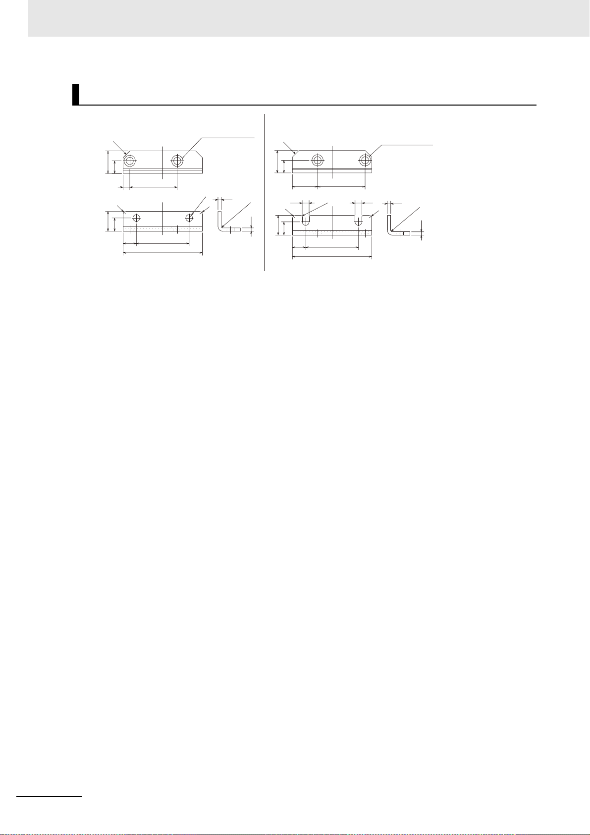
2 Models and External Dimensions
R88A-TK04K
2-C5
2-M4 countersunk
BottomTop
2-C5
2-M4 countersunk
2.5
17
9.5
4-R1
40±0.2
36±0.2
60
5.2
R2
2.5
R1 max.
2.5
19
5.2
R2
15
10
10
17
9.5
36±0.2
5
R2
15
10
40±0.2
10
60
2-ø5.2
R2
2.5
R1 max.
2 - 62
OMNUC G5-series (Pulse-train Input Type) AC Servomotors and Servo Drives User’s Manual
 Loading...