

Page 1
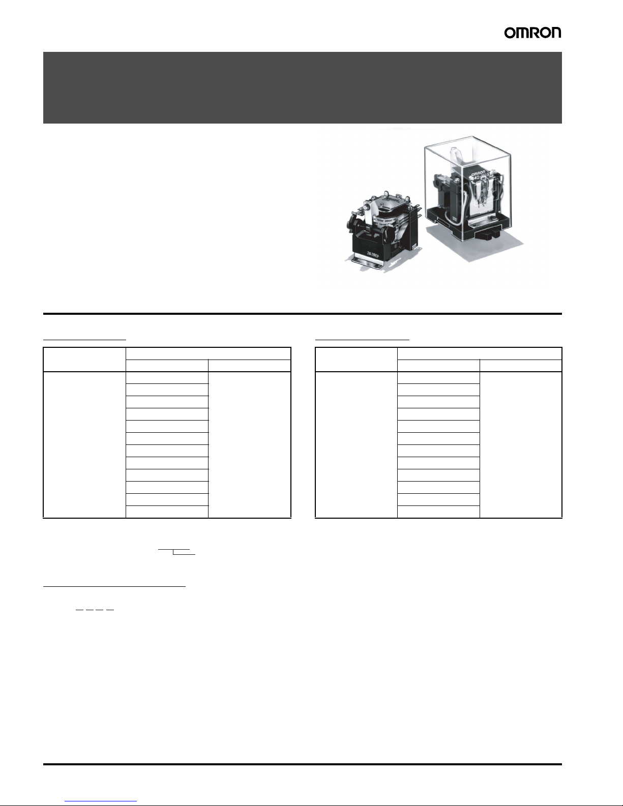
208 Ratchet Relay G4Q
Ratchet Relay
G4Q
Unique Ratchet Mechanism Assures Positive
Alternate Transfer/Switching Operation
• Each contact in the double-pole contact mechanism performs
alternate make-brake operation at each pulse input and is thus
ideal for alternate operation or transfer/switching operation of a
motor.
• Positive operation is assured due to the unique ratchet mechanism.
• Satisfies dielectric strength of 2,000 VAC.
• Low power consumption.
(AC: approx. 6.4 VA; DC: approx. 3.9 W)
Ordering Information
Open Models Plug-in Models
Model Number Legend
1. Contact Form
2: DPDT
2. Contact Type
1: Single
3. Enclosure Construction
1: No casing
2: Casing
4. Terminal Shape
A: Solder
S: Plug-in
Item DPDT
Rated voltage (V) Model
Basic model 6 VAC G4Q-211A
12 VAC
24 VAC
50 VAC
100/(110) VAC
200/(220) VAC
6 VDC
12 VDC
24 VDC
48 VDC
100 VDC
200 VDC
Item DPDT
Rated voltage (V) Model
Basic model 6 VAC G4Q-212S
12 VAC
24 VAC
50 VAC
100/(110) VAC
200/(220) VAC
6 VDC
12 VDC
24 VDC
48 VDC
100 VDC
200 VDC
Rated coil voltage
Note: When ordering, add the rated coil voltage (listed in Specifications) to the model number.
Example: G4Q-211A, 24 VAC
G4Q-@@@@
1 2 3 4
Page 2

Ratchet Relay G4Q 209
■ Accessories (Order Separately)
Specifications
■ Coil Ratings
Note: 1. The rated current and coil resistance are measured at a coil temperature of 23°C with tolerances of +15%/–20% for AC rated current and
±15% for DC coil resistance.
2. The AC coil resistance values are for reference only.
3. Performance characteristic data is measured at a coil temperature of 23
°C.
4. The maximum voltage is one that is applicable instantaneously to the Relay coil at an ambient temperature of 23
°C and not continuously.
5. The AC power consumption is measured at 60 Hz.
■ Contact Ratings
DIN track/Front-connecting Socket Back-connecting Socket
Screw terminal Solder terminal
8PFA1 PL08
Item Current (mA) Resistance (Ω) Must operate Must release Max. voltage Power consumption
Rated voltage (V) 50 Hz 60 Hz % of rated voltage Initial Rated
AC 6 1,233 1,067 0.54 80 % max. 10 % min. 110 % max. Approx.
13.5 VA
Approx.
6.4 VA
12 614 531 2.24
24 307 266 8.7
50 148 128 42.7
100/
(110)
74 64/73.5 160
200/
(220)
37 32/36.8 671
Item Current (mA) Resistance (
Ω) Must operate Must release Max. voltage Power consumption
Rated voltage (V) 50 Hz 60 Hz % of rated voltage
DC 6 640 9.4 5 % min. Approx. 3.9 W
12 320 37.5
24 155 155
48 80 600
100 39 2,580
200 19.2 10,400
Load Resistive load
(cos
φ = 1)
Inductive load
(cosφ = 0.4)
(L/R = 7 ms)
Contact mechanism Single
Contact material Silver alloy
Rated load 5 A at 220 VAC, 5 A at 24 VDC 3 A at 220 VAC, 4 A at 24 VDC
Rated carry current 5 A
Max. switching voltage 250 VAC, 250 VDC
Max. switching current 5 A
Page 3
210 Ratchet Relay G4Q
■ Characteristics
Note: 1. The data shown above are initial values.
2. The contact resistance was measured with 0.1 A at 5 VDC using the voltage drop method.
3. The operate time was measured with the rated voltage imposed with any contact bounce ignored at an ambient temperature of 23
°C.
4. The insulation resistance was measured with a 500-VDC megger applied to the same places as those used for checking the dielectric
strength.
5. The electrical endurance was measured at an ambient temperature of 23
°C.
6. This value was measured at a switching frequency of 60 operations per minute. The value in parentheses is for the cased model.
Engineering Data
Contact resistance (See note 2.) 50 mΩ max.
Operate time (See note 3.) 60 ms max.
Max. operating frequency Mechanical: 1,200 operations/hr
Electrical: 1,200 operations/hr (under rated load)
Insulation resistance (See note 4.) 100 M
Ω min. (at 500 VDC)
Dielectric strength 2,000 VAC, 50/60 Hz for 1 min between coil and contact (1,000 VAC, 50/60 Hz for 1 min between con-
tacts of same polarity) (2,000 VAC between contacts of different polarities)
Vibration resistance Destruction: 10 to 55 to 10 Hz, 0.75 mm single amplitude (1.5 mm double amplitude)
Malfunction: 10 to 55 to 10 Hz, 0.5 mm single amplitude (1.0 mm double amplitude)
Shock resistance
Destruction: 500 m/s
2
Malfunction: 100 m/s
2
Endurance Mechanical: 5,000,000 operations min. (at operating frequency of 1,200 operations/hr)
Electrical: 500,000 operations min. (under rated load and at operating frequency of
1,200 operations/hr) (See note 5.)
Error rate (See note 6.) 1 A at 5 VDC (0.1 A at 5 VDC)
Ambient temperature Operating: –10
°C to 55°C (with no icing or no condensation)
Ambient humidity Operating: 5% to 85%
Weight Open model: Approx. 240 g; cased model: Approx. 340 g
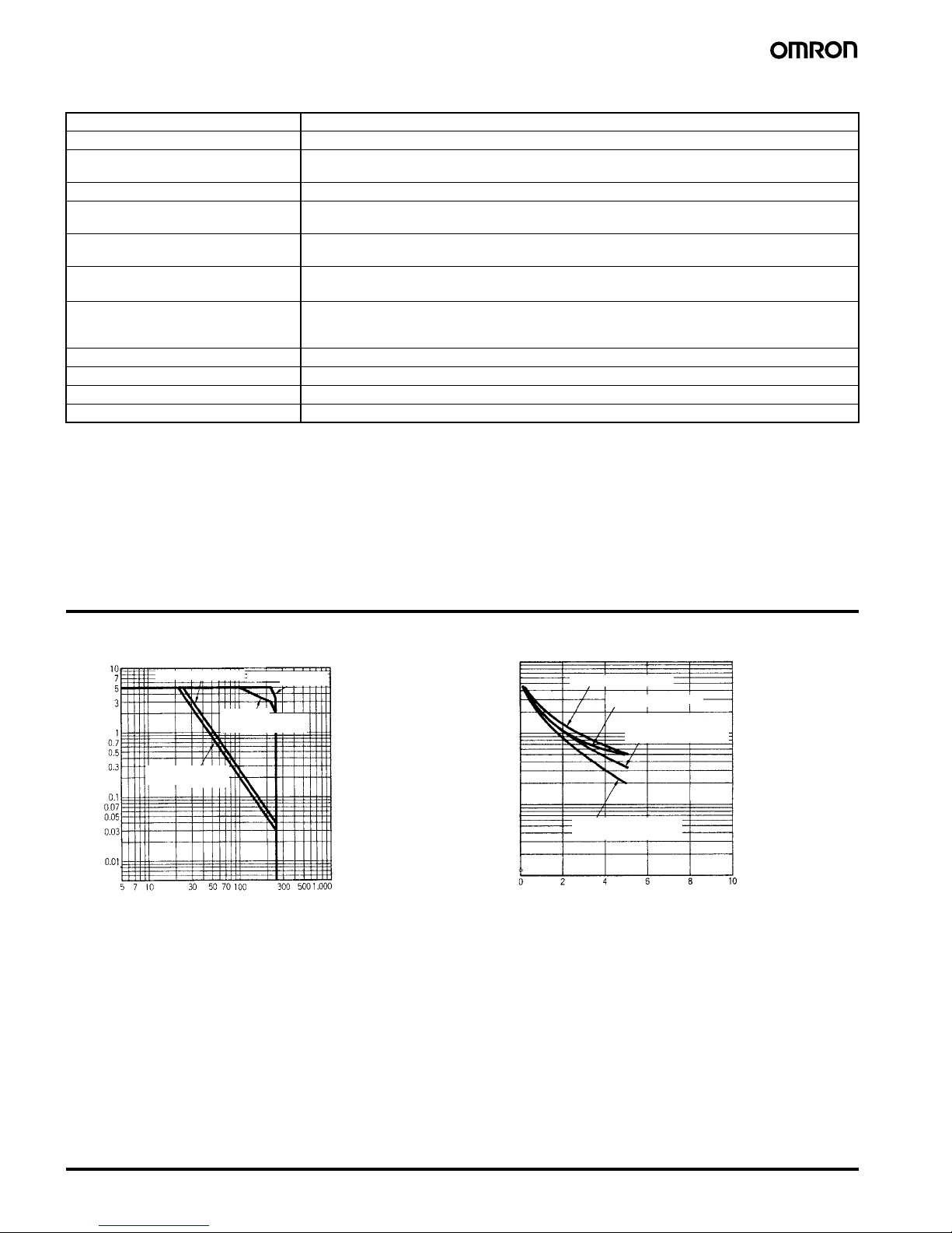
Maximum Switching Power
DC resistive load
AC resistive load
AC inductive load
(cosφ = 0.4)
DC inductive load
L/R = 7 ms
Switching current (A)
Switching voltage (V)
220 VAC resistive load
24 VDC resistive load
24VDC inductive load
L/R = 7 ms
220 VAC inductive load
(cosφ = 0.4)
Electrical Endurance
Switching current (A)
Endurance (x10 operations)
3
100
300
500
700
1,000
3,000
5,000
7,000
10,000
70
50
30
Page 4
Ratchet Relay G4Q 211
Operation
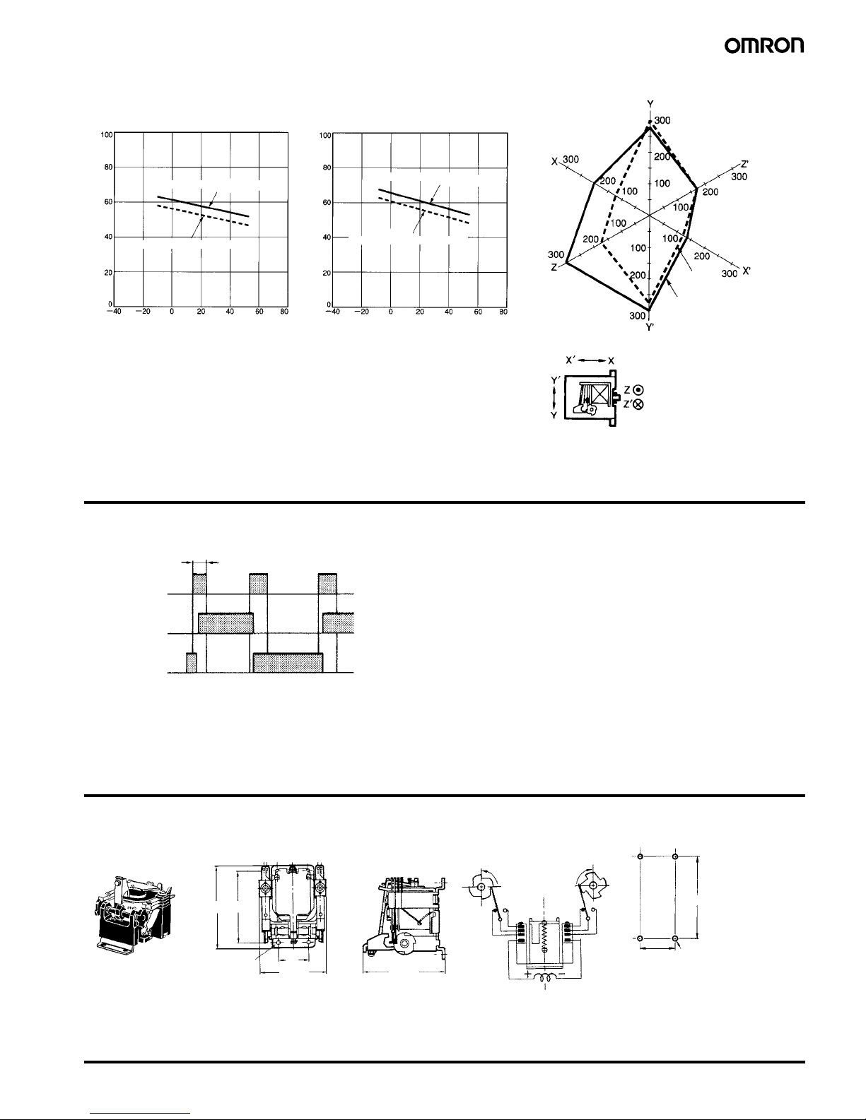
Note: When a pulse for application to the coil is used, such a pulse
should have a width of 100 ms or more. If a pulse is applied with
a width less than the operate time, the cam may fail to rotate
fully.
Dimensions
Note: All units are in millimeters unless otherwise indicated.
Ambient Temperature vs.
Coil Temperature Rise
100 VAC 50 Hz
Coil temperature rise ( C)
°
Contact carry current: 5 A
Contact with no carry current
Ambient temperature (°C)
24 VDC
Coil temperature rise ( C)
Contact carry current: 5 A
Contact with no carry current
Ambient temperature (°C)
Malfunctioning Shock
Not
energized
Energized
Unit: m/s
2
Number of samples: 5
Measurement conditions:
Impose a shock of
100 m/s
2
in the ±X, ±Y, and
±Z directions three times
each with the Relay
energized and not
energized to check the
shock values that cause
the Relay to malfunction.
Shock direction
°
100 ms min.
Contact terminal
(NO) (1−3, 8−6)
Contact terminal
(NC) (1−4, 8−5)
Coil terminal
Operation Timing Chart
66.5 max. 58
Four, 3.5-dia.
mounting holes
25
56 max. 65 max.
Four, M3 mounting
screw holes or four
3.5-dia. holes
Open Model
G4Q-211A
Terminal Arrangement/
Internal Connections
Mounting Holes
58±0.2
25±0.2
Page 5
212 Ratchet Relay G4Q
In the interest of product improvement, specifications are subject to change without notice.
ALL DIMENSIONS SHOWN ARE IN MILLIMETERS.
To convert millimeters into inches, multiply by 0.03937. To convert grams into ounces, multiply by 0.03527.
Cat. No. J070-E1-04
Precautions
Refer to page 11 for general precautions.
■ Surface Mounting Socket
Be sure to provide a mounting space according to the width of the
Relay. The width of the Relay is 63.5 mm and the width of the Socket
is 51 mm.
■ Mounting
Mount the Relay so that the coil faces upward and the cam faces
downwards with the mounting plate secured vertically. Do not
change the cam angle.
Make sure that Relay terminals are free of flux or any other foreign
substance before soldering the Relay terminals.
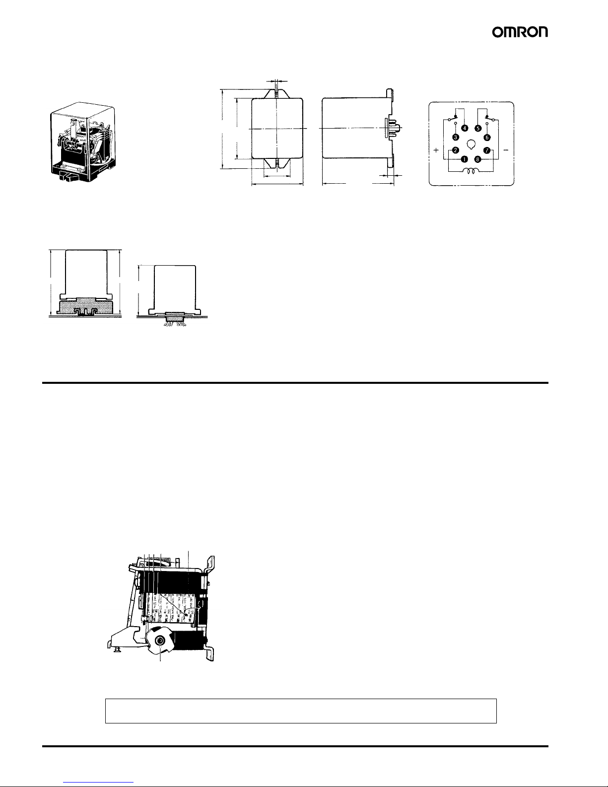
92.5
max.
71.5
max.
30.5
63.5 max.
80 max.
Plug-in Terminal Model
G4Q-212S
Terminal Arrangement/
Internal Connections
(Bottom view)
3.5
7
102
100
80
Relay Mounting Height with Socket
With Front-connecting
Socket
With Back-connecting
Socket
G4Q212S
G4Q212S
8PFA1 PL08
Coil
Cam
 Loading...