

Page 1
Slim Relay G3RV 1
Slim Relay
G3RV
The World's First Industrial Slim Relay
• G2RV compatible
• LED indicator built in SSR
• Push-in terminals and accessories for easy wiring.
Model Number Structure
■ Model Number Legend
1. Basic Model Name
G3RV: MOS-Solid State Relay
2. Auxiliary Type Designation
SL: Slim Solid State Relay and socket combination
3. Wire Connection
700: Screw Terminals
500: Push-in (screwless) terminals
4. Output voltage specifications
A(L): AC Output .. TRIAC
* A: with Zero cross function AL: without Zero cross function
D: DC Output .. MOS FET
Ordering Information
■ List of Models
Relay and Socket Combinations
123 4
G3RV-SL @ @ @ - @
Classification Enclosure rating Input voltage Type of connection Contact form
SPST
Plug-in terminals General-purpose Unsealed AC/DC Screw terminals G3RV-SL700
Push-in terminals G3RV-SL500
Input voltage Screw terminals Push-in terminals
12 VDC G3RV-SL700-D 12VDC G3RV-SL500-D 12VDC
G3RV-SL700-A(L) 12VDC G3RV-SL500-A(L) 12VDC
24 VDC G3RV-SL700-D 24VDC G3RV-SL500-D 24VDC
G3RV-SL700-A(L) 24VDC G3RV-SL500-A(L) 24VDC
24 VAC/DC G3RV-SL700-D 24VAC/DC G3RV-SL500-D 24VAC/DC
G3RV-SL700-A(L) 24VAC/DC G3RV-SL500-A(L) 24VAC/DC
48 VAC/DC G3RV-SL700-D 48VAC/DC G3RV-SL500-D 48VAC/DC
G3RV-SL700-A(L) 48VAC/DC G3RV-SL500-A(L) 48VAC/DC
110 VAC G3RV-SL700-D 110VAC G3RV-SL500-D 110VAC
G3RV-SL700-A(L) 110VAC G3RV-SL500-A(L) 110VAC
230 VAC G3RV-SL700-D 230VAC G3RV-SL500-D 230VAC
G3RV-SL700-A(L) 230VAC G3RV-SL500-A(L) 230VAC
Page 2
2 Slim Relay G3RV
Specifications
■ Ratings (at an Ambient Temperature of 25°C)
Input
G3RV-SL700/500-A Series
G3RV-SL700/500-AL Series
G3RV-SL700/500-D Series
Output
Rated voltage Rated current Must operate
voltage
Must release
voltage
Input voltage
AC DC % of rated voltage
50 Hz 60 Hz
12 VDC --- --- 15 mA 10.8V 1V ±10%
24 VDC --- --- 12 mA 21.6V
24 VAC/DC 20 mA 21 mA 11 mA 21.6V
48 VAC/DC 10 mA 11 mA 6 mA 43.2V
110 VAC 7.5 mA 8.2 mA --- 99V
230 VAC 7.3 mA 8.6 mA --- 207V
Rated voltage Rated current Must operate
voltage
Must release
voltage
Input voltage
AC DC % of rated voltage
50 Hz 60 Hz
12 VDC --- --- 8 mA 10.8V 1V ±10%
24 VDC --- --- 4.5 mA 21.6V
24 VAC/DC 10.7 mA 11.1 mA 4.3 mA 21.6V
48 VAC/DC 9.6 mA 10.2 mA 6 mA 43.2V
110 VAC 6.8 mA 7.5 mA --- 99V
230 VAC 6.8 mA 8.1 mA --- 207V
Item G3RV-SL700/500-A(L) G3RV-SL700/500-D
Rated load voltage AC100~240V (50/60Hz) DC5~24V
Load voltage range AC75~264V (50/60Hz) DC3~26.4V
Load current 0.1~2A (Ta=40°C) 100µA~3A (Ta=40°C)
Inrush current 30A (60Hz/1cycle) 30A (60Hz/1cycle)
Permissible I
2
t ; Joule Integral
(Reference value)
15A2s9A
2
s
Application load capacity 400W
(Output voltage: AC200V)
72W
(Output voltage: DC24V)
Page 3
Slim Relay G3RV 3
■ Characteristics
■ Approved Standards
UL 508 (File No. E64562)
IEC/TUV (EN 62314)
Item G3RV-SL700/500-A G3RV-SL700/500-AL G3RV-SL700/500-D
Output ON voltage drop 1.6 V rms max. 0.9 V max.
Leakage current 5 mA max. (at 200 VAC 50/60Hz) 10 µA max. (at 24VDC)
Insulation resistance 100 MΩ min. (at 500 VDC)
Dielectric strength AC2500V 50/60 Hz for 1 min between input and output
Vibration resistance Malfunction: 10 to 55 to 10 Hz, 0.7-mm single amplitude
Shock resistance
300m/s
2
Ambient temperature Storage: -30~+100°C (with no icing or condensation)
Operating: -30~+55°C (with no icing or condensation)
Ambient humidity 45~85%RH
Weight Approx. 38 g
Pollution degree 2
Degree of protection according
to IEC 60529
IP20
Rated Impulse Withstand
Vo lt ag e
4.0kV / III
Load category LC-A DC-12
Overload Current Profile 1.5Ie 1.1Ue
5s ON, 10s OFF, 10cycles
Rated insulation Voltage 240V
Model Input ratings Contact ratings
G3RV-SL700/500-D Series 12, 24 VDC
24, 48 VAC/DC
110, 230 VAC
24 VDC 3 A (Resistive Load) at 25°C
G3RV-SL700/500-A(L) Series 12, 24 VDC
24, 48 VAC/DC
110, 230 VAC
240 VAC 2 A (Resistive Load) at 25°C
Input ratings Contact ratings
12, 24 VDC
24, 48 VAC/DC
110, 230 VAC
24 VDC 3 A (Resistive Load)
12, 24 VDC
24, 48 VAC/DC
110, 230 VAC
240 VAC 2 A (Resistive Load)
Page 4
4 Slim Relay G3RV
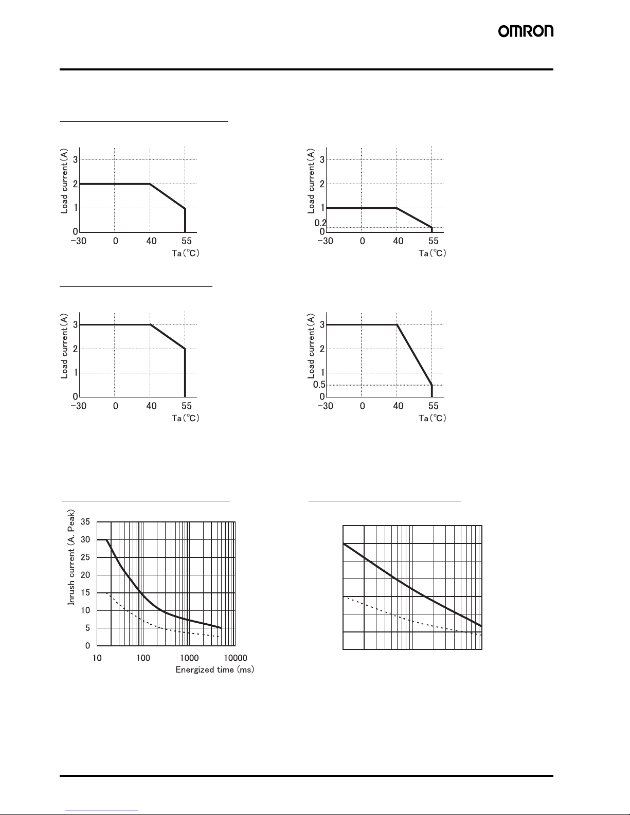
Engineering Data
■ Load current derating curves
G3RV-SL700/500-A(L) Series
G3RV-SL700/500-D Series
■ One Cycle Surge Current: Non-repetitive
Non-repetitive (Keep the inrush current to half the rated value if it occurs repetitively.)
The values shown by the solid line are for non-repetitive inrush currents.
Mounting Distance 10mm Mounting Distance 0mm
Mounting Distance 10mm Mounting Distance 0mm
G3RV-SL700/500-A(L) Series G3RV-SL700/500-D Series
㪇
㪌
㪈㪇
㪈㪌
㪉㪇
㪉㪌
㪊㪇
㪊㪌
㪈㪇 㪈㪇㪇 㪈㪇㪇㪇
㪜㫅㪼㫉㪾㫀㫑㪼㪻㩷㫋㫀㫄㪼㩷㩿㫄㫊㪀
㪠㫅㫉㫌㫊㪿㩷㪺㫌㫉㫉㪼㫅㫋㩷㩿㪘㪅㩷㪧㪼㪸㫂㪀
Page 5
Slim Relay G3RV 5
Accessories
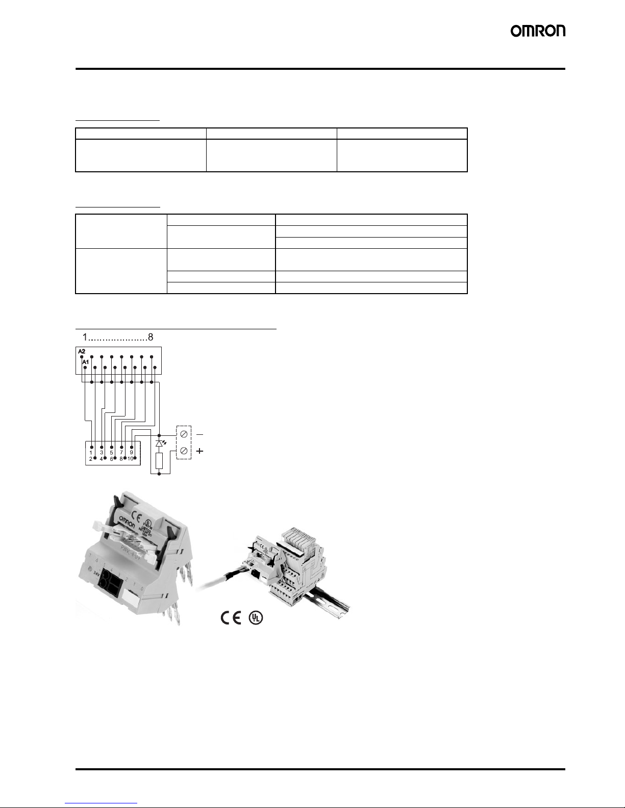
■ PLC Interface (for G2RV-SL700 & G3RV-SL700 series only)
List of Models
Specifications
Electrical schematic P2RVC-O-8-F
Model number Description Connection
P2RVC-8-O-F PLC Output Interface for 8x
G2RV-SL700 & G3RV-SL700 series
PNP - type
Ribbon cable connector
10 Pole, IEC603/1
Input Rated voltage 30 VAC/VDC max.
Current capacity 0.5 A per channel
2.0 A total current, power supply terminal
Characteristics Ambient temperature Operating: 0 to 55°C
Storage: − 20 to 85°C
Overvoltage category III
Pollution degree 2
Page 6

6 Slim Relay G3RV
■ SSR for Maintenance
Model Number Legend
1. Output voltage specifications
D: DC Output
2: AC Output
2. Rated Current
02: AC Output 2A
03: DC Output 3A
3. Terminals
S: Plug-In
4. Zero cross function
Blank: with Zero cross function
L : without Zero corss function
List of Models
* different by ambient temperature.
Please refer to 4 pages of characteristic data “ ■ Load current derating curves” for the details.
123 4
G3RV-@ @ @ @
Isolation Movement
indication
Rated input
voltage
(Socket)
Output
(SSR)
Zero cross
function
Rated
output
load*
Model Number Replacement for
Phototriac Yes (Green) DC12V AC Yes 2A at 100
to 240VAC
G3RV-202S DC12 G3RV-SL700/500-A DC12
DC24V G3RV-202S DC24 G3RV-SL700/500-A DC24
AC/DC24V G3RV-SL700/500-A AC/DC24
AC/DC48V G3RV-SL700/500-A AC/DC48
AC110V G3RV-202S DC48 G3RV-SL700/500-A AC110
AC230V G3RV-SL700/500-A AC230
DC12V No G3RV-202SL DC12 G3RV-SL700/500-AL DC12
DC24V G3RV-202SL DC24 G3RV-SL700/500-AL DC12
AC/DC24V G3RV-SL700/500-AL AC/DC24
AC/DC48V G3RV-SL700/500-AL AC/DC48
AC110V G3RV-202SL DC48 G3RV-SL700/500-AL AC110
AC230V G3RV-SL700/500-AL AC230
Photocoupler DC12V DC --- 3A at 5 to
24 VDC
G3RV-D03SL DC12 G3RV-SL700/500-D DC12
DC24V G3RV-D03SL DC24 G3RV-SL700/500-D DC24
AC/DC24V G3RV-SL700/500-D AC/DC24
AC/DC48V G3RV-D03SL DC48 G3RV-SL700/500-D AC/DC48
AC110V G3RV-SL700/500-D AC110
AC230V G3RV-SL700/500-D AC230
Page 7

Slim Relay G3RV 7
■ Cross bars
Model Number Legend
1. Number of Poles 2. Color
020: 2 poles R: Red
030: 3 poles S: Blue
040: 4 poles B: Black
100: 10 poles
200: 20 poles
List of Models
@ select color: R = Red, S=Blue, B=Black
Specification
■ Plastic Labels for G2RV/G3RV Sockets
■ Labels (Stickers) for G2RV/G3RV Sockets
Model number Poles Quantity Color
P2RVM-020@ 2 60 pcs / box (minimum order)
Red (R)
Blue (S)
Black (B)
P2RVM-030@ 3 60 pcs / box (minimum order)
P2RVM-040@ 4 60 pcs / box (minimum order)
P2RVM-100@ 10 20 pcs / box (minimum order)
P2RVM-200@ 20 20 pcs / box (minimum order)
Max current
(EN60947-7-1 section 8.3.3 / 1991)
32A
Max. Voltage 400 VAC
Max. Voltage
when cutting Cross-bar without using separation
plate or end-bracket
250 VAC
12
P2RVM -@ @
Model number Box quantity Color
R99-15 for G2RV 5 sheets × 120 labels =
600 labels (minimum order)
White
Model number Box quantity Color
R99-16 for G2RV 10 sheets × 484 labels =
4,840 labels (minimum order)
White
Page 8

8 Slim Relay G3RV
■ Separating Plates
Dimensions
Note: All units are in millimeters unless otherwise indicated.
Complete Unit
G3RV-SL700
Model number Quantity Description
P2RV-S 50 plates Provides isolation between
adjacent relays to achieve
400 V isolation.
Five,
M2.5 × 6
6.2 max.
99.2
7.1
88.9
26.1
47.2
70.9
83
106.7 max.
92.7 max.
35
Input circuit
24 V DC
Terminal Arrangement/
Internal Connections
(Top View)
Other Input Voltage
Terminal Arrangement/
Internal Connections
(Top View)
12 V DC
Terminal Arrangement/
Internal Connections
(Top View)
Page 9

Slim Relay G3RV 9
G3RV-SL500
Solid State Relay
Input circuit
24 V DC
Terminal Arrangement/
Internal Connections
(Top View)
Other Input Voltage
Terminal Arrangement/
Internal Connections
(Top View)
12 V DC
Terminal Arrangement/
Internal Connections
(Top View)
6.2 max.
99.2
88.9
7.1
24.6
46
69.8
82.9
106.7 max.
97.4 max.
35
G3RV-D03SL
G3RV-202S(L)
Input circuit
G3RV-D03SL G3RV-202S(L)
PD[
PD[
PD[
Terminal Arrangement/
Internal Connections
(Bottom View)
Page 10
10 Slim Relay G3RV
Installation
■ Tools
G3RV-SL700 series: Flat-Blade screwdriver should be used for mounting and / or releasing cables.
G3RV-SL500 series: Flat-Blade screwdriver should be used for mounting stranded wires without ferrules and / or releasing cables.
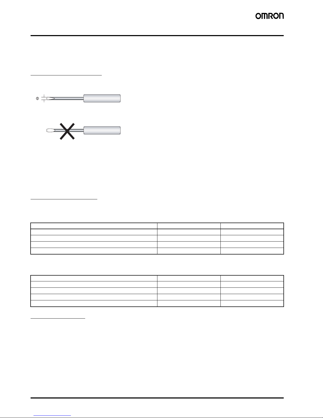
Applicable Screwdriver
● Flat-blade, Parallel-tip, 2.5 mm diameter (3.0 mm max.)
Examples: FACOM AEF.2.5 × 75E (AEF. 3 × 75E)
VESSEL No. 9900-(-)2.5 × 75 (No. 9900-(-)3 × 100)
WAGO 210-119
WIHA 260/2.5 × 40 (260/3 × 50)
*Chamfering the tip of the driver improves insertion when used as an exclusive tool.
■ Applicable Wires
Applicable Wire Sizes
G3RV-SL700 Series
Box clamp technology
G3RV-SL500 Series
Push-in technology
Tightening torque
G3RV-SL700 Series: 0.4Nm
2.5 dia. (3.0 mm max.)
Cannot be used.
● Flat-blade, Flared-tip
● Flat-blade, Parallel-tip
Wire type Applicable wire size Stripping length
Stranded without ferrules
0.5 - 1.5 mm
2
7mm
Stranded with ferrules and plastic collar
0.5 - 1.5 mm
2
7mm
Stranded with ferrules without plastic collar
0.5 - 1.5 mm
2
7mm
Solid
0.5 - 1.5 mm
2
7mm
Wire type Applicable wire size Stripping length
Stranded without ferrules
0.5 - 1.5 mm
2
12 mm
Stranded with ferrules and plastic collar
0.5 - 1.5 mm
2
12 mm
Stranded with ferrules without plastic collar
0.5 - 1.5 mm
2
12 mm
Solid
0.5 - 1.5 mm
2
12 mm
Page 11

Slim Relay G3RV 11
■ Wiring
Use wires of the applicable sizes specified above. The length of the exposed conductor should be 7 mm for a G3RV-SL700 series, 12 mm for a
G3RV-SL500 series.
Wiring Procedure for G3RV-SL500 series
● Wiring
Insert the exposed conductor into the connection hole.
No other tools are required.
Note: In case of wiring stranded wires without ferrules screwdriver
should be inserted before inserting the wire.
Screwdriver should be removed after fully insertion of the wire.
● Removing
Insert the specified screwdriver into the release hole.
Removing wire.
Removing screwdriver.
7 mm
Fig. 1 Exposed Conductor Length
12 mm
G3RV-SL700
G3RV-SL500
Screwdriver hole
Wire connection hole
Wire
Page 12

12 Slim Relay G3RV
Precautions
Precautions for Connection
• Do not move the screwdriver up, down, or from side to side while it
is inserted in the hole. Doing so may cause damage to internal
components (e.g., deformation of the clamp spring or cracks in the
housing) or cause deterioration of insulation.
• Do not insert the screwdriver at an angle. Doing so may break the
side of socket and result in a short-circuit.
• Do not insert two or more wires in the hole. Wires may come in
contact with the spring causing a temperature rise or be subject to
sparks.
• Inser t the screwdriver along the hole wall as shown below.
• If lubricating liquid, such as oil, is present on the tip of screwdriver,
the screwdriver may fall out resulting in injury to the operator.
• Inser t the screwdriver into the bottom of the hole. It may not be
possible to connect cables properly if the screwdriver is inserted
incorrectly.
General Precautions
• Do not use the product if it has been dropped on the ground.
Dropping the product may adversely affect performance.
• Confirm that the socket is securely attached to the mounting track
before wiring. If the socket is mounted insecurely it may fall and
injure the operator.
• Ensure that the socket is not charged during wiring and
maintenance. Not doing so may result in electric shock.
• Do not pour water or cleansing agents on the product. Doing so
may result in electric shock.
• Do not use the socket in locations subject to solvents or alkaline
chemicals.
• Do not use the socket in locations subject to ultraviolet light (e.g.,
direct sunlight). Doing so may result in markings fading, rust,
corrosion, or resin deterioration.
• Do not dispose the product in fire.
Removing from Mounting Rail
To remove the socket from the mounting rail, insert the tip of
screwdriver in the fixture rail, and move it in the direction shown
below.
Screwdriver
Page 13

Slim Relay G3RV 13
Definition of Precautionary Information
Precautions for Safe Use
● Transpporting
Do not use or store the G3RV in the following transporting.
of Doing so may result in damage, mulfunction, or detericration
of performance characteristics.
• Conditions under which the G3RV will be exposed to water.
• High temperatures or high humidity.
• Without proper packing.
● Operating and Strage Locations
Do not use or store the G3RV, in the following locations. Doing so
may result in damage, mulfunction, or detericration of
performance characteristic.
• Locations subject to rain or water drops.
• Locations subject to exposure to water, or oil, or chemicals.
• Locations subject to high temperatures or high humidity.
• Locations subject to ambient temperatures outside the range
from -30 to +100 centigrade.
• Locations subject to relative humidity outside the range 45% to
85%.
• Locations subject to corrosive or ammable gasses.
• Locations subject to dust (especially iron dust) or salts.
• Locations subject to barrier.
● Handring
• Must need an air convection for G3RV or the heat convection air
producess a heating on G3RV abnormal and causes a
short-circuit failure and burning.
• Do not use the G3RV with terminal bending due to dropping etc.
Bent terminal may poorly tting electrical contacts, leading to
trouble.
• Do not carry out the mounting work with hand stained with oil or
metal powder. Otherwise, trouble may be caused.
● Mounting
• Mount the G3RV in the speci ed orientation. If the G3RV is
mounted in any other orientation, abnormal heat generation
may cause output elements to short or may cause burning.
• Be sure to prevent the ambient temperature from rising due to
the heat radiation of the G3RV. If the G3RV is mounted a panel,
install a fan so that the interior of the panel is fully inside
ventilated.
• Be sure that the G3RV clicks into place when mounting it to DIN
Track. The G3RV may fall if it is not mounted correctly.
● Wiring
• Use a wire an adequate size for current to be applied. Abnormal
heating of wire may cause burning.
• Do not use any wires with damaged sheaths. These may caus
electric shock leakage.
• Con rm it wire for G3RV is not used in pipe or duct for high
voltage power supply.Induction will be generated and cause
malfunction or damages.
• Be sure to conduct wiring with the power supply turned OFF.
Touching the terminals when they are charged may occationally
result in minor electric shock.
● Using
• Select a load within the rated range. Inappropriate load may
cause misoperation, trouble or burning.
• Select the power supply within the rated frequency range.
Inappropriate power frequency may cause misoperation, trouble
or burning.
Precautions for Correct Use
● G3RV uses electronics parts mounting on PCB, so that any
dropping and vibration, physical shock beyond the standard level
should beprevented, otherwise the initial characteristic will be not
injured.
● Terminal screw must be tightened with regulation torque. Less
convection air produces a heating on G3RV abnormal and causes
a short-circuit failure and burning.
(M2.5, 0.4 N•m)
● Do not supply a high voltage/current to the input and output. Short
circuit failure or burning must be occured on G3RV.
● Do not use or store the G3RV, in the following locations. Doing so
may result in damage, malfunction, or deterioration of
performance characteristic.
• Locations subject to static electricity or other forms of noise.
• Locations subject to strong electromagnetic elds.
• Locations subject to possible exposure to radioactivity.
WARNING
Indicates a potentially hazardous situation which,
if not avoided, will result in minor or moderate
injury, or may result in serious injury or death.
Additionally there may be significant property
damage.
CAUTION
A potentioally hazardous situation by misuse,
may result in property damage only accident.
CAUTION
Minor hazard by electric shock may occasionally occur.
Do not touch the G3RV's terminal (Charging part) while
the power supply turned on.
The G3RV may occasionally rupture in case of a short
circuit.
To protect against short-circuit accident, install a
protective device, such as a quick-burning fuse or a
circuit breaker or the like, on the power supply.
Minor hazard by electric shock may occasionally occur.
Do not touch the G3RV's main circuit terminals
immediately after the power is turned OFF.
The internal snubber circuit is charged.
* 202S,SL,G3RV-A(L) Type only
Minor hazard by burns may occasionally occur.
Do not touch the G3RV or the heat sink either while the
power supply is ON, or immediately after the power is
turned OFF.
The G3RV and the heat sink will be hot.
Page 14
14 Slim Relay G3RV
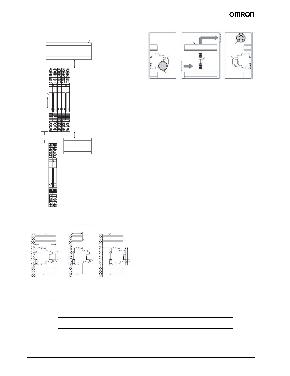
● Mounting
<SSR Mounting Pitch (Panel Mountin)>
<Relations between SSR and duct (Depth of duct)>
<Ventilation Outside the Control Panel>
* If the air inlet or air outlet has a lter, clean the lter regularly to
prevent it from cogging to ensure an e cient ow of air.
* Do no locate any objects around the air inlet or air outlet, otherwise
the objects may obstruct the proper ventilation of the control panel.
* A heat exchanger, if used, should be located in front the G3RVs to
ensure the eciency or the heat exchanger.
* Please reduce the ambient temperature of G3RVs. The rated load
current of a G3RV is measured at an ambient temperature of 25°C.
* A G3RV uses semiconductor in the output element.
This causes the temperature inside the control panel to increase
due to heating resulting from the passeage of electrical current
through the load. To the restrict heating, attach a fan to the
ventilation outlet or air inlet of the control panel to ventilate the
panel. This will reduce the ambient temperature of the G3RVs and
thus increase reliability.
(Generally, each 10°C reduction in temperature will double the
expected life.)
● EMI
• This is a class A product. In residential areas it may cause redio
interference, in which case the user may be required to take
adequate measures to reduce interference.
Suitability for Use
OMRON shall not be responsible for conformity with any standards,
codes, or regulations that apply to the combination of the products in
the customer's application or use of the product.
Take all necessary steps to determine the suitability of the product
for the systems, machines, and equipment with which it will be used.
Know and observe all prohibitions of use applicable to this product.
NEVER USE THE PRODUCTS FOR AN APPLICATION INVOLVING SERIOUS
RISKTO LIFE OR PROPERTY WITHOUT ENSURING THAT THE SYSTEM AS A
WHOLE HAS BEEN DESIGNEDTOADDRESSTHE RISKS, ANDTHATTHE OMRON
PRODUCT IS PROPERLY RATED AND INSTALLED FOR THE INTENDED USE
WITHIN THE OVERALL EQUIPMENT OR SYSTEM.
See also Product catalog for Warranty and Limitation of Liability.
Duct
60mm min.
80mm min.
30mm min.
SSR
Vertical
direction
Counter measure(1)Duct Depth Counter measure(2)
Duct or air flow
obstruction
The depth
of SSR
SSR
SSR
SSR
Vertical
direction
Duct or air flow obstruction Duct or air flow
obstruction
Duct or air flow obstruction
The recommended width is
1/2 as large as the depth of
SSR or less
Duct or air flow
obstruction
Air flow
Duct or air flow
obstruction
Do not surrounded the SSR
with the duct in the depth
direction, or otherwise the
heat radiation of the S5R
will be adversely affected.
If the height of the ducts
can not be lowered, place
the SSR or a metal base so
that they are not
surrounded by the ducts.
Use a short duct in
the depth direction.
Metal
base
SSR
SSR
SSR
Air inlet
Be aware of air flow
Duct
Ventllation
outlet
In the interest of product improvement, specifications are subject to change without notice.
ALL DIMENSIONS SHOWN ARE IN MILLIMETERS.
To convert millimeters into inches, multiply by 0.03937. To convert grams into ounces, multiply by 0.03527.
Cat. No. J180-E1-01
 Loading...