

Omron G3PX-220EH-CT03, G3PX-220EUN, G3PX-260EUN, G3PX-240EUN, G3PX-260EH-CT03 User Manual
...Page 1
1
Power Controller G3PX
Single-phase Models
EUN
Series
AC Power Controller with Phase-control
System Allows Precise Temperature
Control
Models with Base-up and Soft-start
Functions Available
EH
Series
Phase Control System Makes It
Possible to Detect Disconnection of
Heaters
EC
Series
Optimum Device for Controlling Input
Power for Pure Metal Heater, and
Incorporates Overcurrent Detecting and
Single Heater Burnout Detecting
Functions
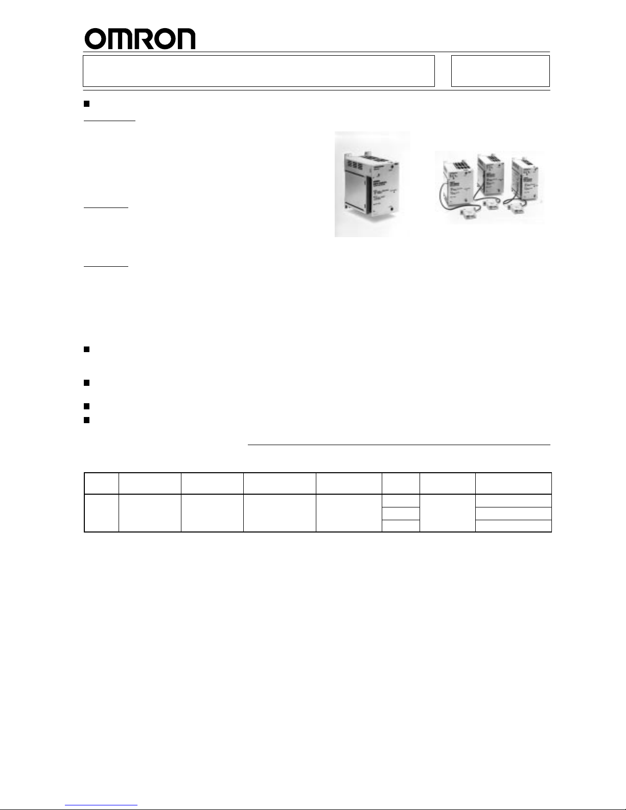
OMRON’s unique design and carefully-selected
materials made it possible to produce a compact
and lightweight Power Controller.
Replaceable, easy-to-install Power Device Cartridge assures ease of maintenance.
Detecting
component failures and operating errors.
On applying for UL, CSA.
Ordering Information
EUN
Series
Phase Applicable
load
Level
indicator
Base-up function
(see note 1)
Soft-start time
Carry
current
Rated
voltage
Model
Single
Resistive load
Yes Yes
Approx. 0.5 to
20 A
100/1
10 V
AC
G3PX-220EUN
Heater
10 sec
40 A
200/230 V
AC
G3PX-240EUN
60 A
(see note 2)
G3PX-260EUN
Note: 1. The
base-up output with a 0-mA temperature controller
output (i.e. the temperature controller is OFF) dif
fers from that with a 4-mA
temperature
controller output. Refer the
Characteristics data
on page
67.
2.
When ordering, make sure that the rated voltage is 200/230 V
AC because the 200/220-V
AC G3PX exists as well.
Page 2
G3PX
G3PX
2
EH
Series
Phase Applicable
load
Level
indicator
Single heater
burnout
detection
Multiple heater
burnout
detection
Carry
current
Rated
voltage
Model
(see note 1)
Single
Resistive load
Yes Yes No
20 A
100/1
10 V
AC
G3PX-220EH-CT03
Heater
00/
0
C
200/230 V
AC
G3PX-220EH-CT10
40 A
200/230 V
AC
(see note 3)
G3PX-240EH-CT03
G3PX-240EH-CT10
60 A
G3PX-260EH-CT03
G3PX-260EH-CT10
Y
es (see note 2)
Yes
20 A
G3PX-220EHN-CT03
G3PX-220EHN-CT10
40 A
G3PX-240EHN-CT03
G3PX-240EHN-CT10
60 A
G3PX-260EHN-CT03
G3PX-260EHN-CT10
Note: 1. EH- and EHN-series models are provided with a CT incorporating 30- or 100-cm-long lead wires and Power Device Cartridge.
When
ordering, specify the length of the lead wires by adding a code to the model number as shown below
.
G3PX-2j
0EH-CT03: CT with 30-cm-long lead wires
G3PX-2j
0EH-CT10: CT with 100-cm-long lead wires
2. Adjusts
the multiple heater burnout
detection sensitivity of EHN-series models. Enables single heater burnout detection in control of
a
maximum of five heaters.
3.
When ordering, Rated voltage should be made sure if it is for 200/230 V
AC. Otherwise 200/220 V
AC G3PX is existing.
EC
Series
Phase Applicable
load
Level
indicator
Constant-current
function
Single heater
burnout
detection
Carry
current
Rated
voltage
Model
(see note 1)
Single
Resistive load
Yes Yes Yes
20 A
100/1
10 V
AC
G3PX-220EC-CT03
Heater
00/
0
C
200/230 V
AC
G3PX-220EC-CT10
40 A
200/230 V
AC
(see note 2)
G3PX-240EC-CT03
G3PX-240EC-CT10
60 A
G3PX-260EC-CT03
G3PX-260EC-CT10
Note: 1. EC-series
models are provided with a CT Unit with lead wires (30- or 100- cm in length). When ordering, specify the length of the
lead
wires by adding a code to the model number as shown below
.
G3PX-2j
0EC-CT03: CT with 30-cm-long lead wires
G3PX-2j
0EC-CT10: CT with 100-cm-long lead wires
2.
When ordering, Rated voltage should be made sure if it is for 200/230 V
AC. Otherwise 200/220 V
AC G3PX is existing.
Accessories (Order Separately)
CT Unit
Name Length
of lead wires
Solderless terminals Applicable models
Model
CT Unit
0.3 m
Yes
G3PX-2jjEH G32X-CT03
CU
1 m
es
G32X-CT10
0.3 m
G3PX-2jjEHN G32X-CT03HN
1 m
G32X-CT10HN
0.3 m
G3PX-2jjEC G32X-CT03C
1 m
G32X-CT10C
Power Device Cartridge
Name Carry
current
Applicable models
Model
Power Device Cartridge
20 A
G3PX-220Ejj G32X-A20
oe eceCa dge
40 A
G3PX-240Ejj G32X-A40
60 A
G3PX-260Ejj G32X-A60
Note:
The G32X-A is a dedicated Power Device Cartridge for the G3PX.
Refer to
Replacement Parts
on page
75.
Page 3

G3PX
G3PX
3
Specifications
Ratings
Control
Item G3PX-
220EUN/
240EUN/
260EUN
G3PX220EH/
240EH/
260EH
G3PX220EHN/
240EHN/
260EHN
G3PX220EC/
240EC/
260EC
Rated
voltage
100/1
10, 200/230 V
AC
Frequency
50/60 Hz (see note 1)
Input
signal for
control
External
main
setting
2 kΩ
(type B, 2 W min.)
3 kΩ
(type B, 2 W min.)
2 kΩ
(type B, 2 W min.)
Current
input
4 to 20 mA (at 1 to 5 V) (Input impedance: 250Ω) (see note 3)
Voltage
ON/OFF
input
5 to 24 VDC (Input impedance: approx. 20 k
Ω)
External
duty
setting
3 kΩ (type B)
Relay output for
alarm
--- SPDT
: 8 A at 250 V
AC/30 VDC
Note: 1.
50/60 Hz (no selector required) (EUN Series)
Terminals 18 and 19 of EHN/EC-series models must be open when the supply frequency is 50 Hz. These terminals must be
short-circuited
when the supply frequency is 60 Hz.
2. Use
the G32X-V2K 2-kΩ V
ariable Resistor for external main setting on EUN, EC, and EHN (G32X-V3K 3-kΩ for EN-series models).
3. Input
4 to 20 mA or 1 to 5 VDC linear input to the 4 to 20 mA current input terminal.
Output
Model
Applicable load
Load voltage range
Load current
Inrush current
Number of phase
G3PX-220Ej
G3PX-220EjN
100/1
10, 200/230 V
AC
(50/60 Hz)
1 to 20 A (see note)
220 A (60 Hz, 1 cycle) Single
G3PX-240Ej
G3PX-240EjN
1 to 40 A (see note)
440 A (60 Hz, 1 cycle)
G3PX-260Ej
G3PX-260EjN
1 to 60 A (see note)
440 A (60 Hz, 1 cycle)
Note:
The G3PX-2jjEHN (model with multiple heater burnout detecting function) and G3PX-2jjEC (constant-current model) require
20% min. of the rated current to detect a short mode failure. EC-series models detect an open mode failure if the load current has
dropped
to 80% of the rated value. A short mode failure will be detected if the current has risen to 20% of the rated value.
Characteristics
EU/EH
Series
Item G3PX-220EUN/
240EUN/260EUN
G3PX-220EH/240EH/260EH G3PX-220EHN/
240EHN/260EHN
Operating
voltage
range
±10%
Operating frequency
range
±1 Hz
Output voltage
adjustable range
0% to 95%
Internal duty setting
range
0% to 100%
10% to 100% (see note 1)
0% to 100%
External duty setting
range
0% to 100%
10% to 100% (see note 1)
0% to 100%
Start-up time
(see note 2)
Approx. 0.5 to 10 s
(see note 3)
Approx. 0.1 to 1 s
(see note 3)
Approx. 0.5 to 10 s
(see note 3)
Base-up range
0% to 90%
---
Multiple heater burnout
detection
---
20% max. (see note 4)
Page 4
G3PX
G3PX
4
Item G3PX-220EHN/
240EHN/260EHN
G3PX-220EH/240EH/260EHG3PX-220EUN/
240EUN/260EUN
Min. phase detection
---
Approx. 1/6
π
Min. phase setting
--- ---
Approx. 1/6
π
Min. load current for
ON error detecting
---
1 A
30% max. of rated current
(see note 5)
Abnormality detection
time
---
0.1 s max.
1 s max.
V
oltage drop with
output ON
1.6 V max. (RMS)
Leakage current
10 mA max. at 100/1
10 V
AC, 20 mA max. at 200/230 V
AC
Insulation resistance
100 MΩ min. (at 500 VDC)
Dielectric strength
2,000 V
AC, 50/60 Hz for 1 min.
V
ibration resistance
Malfunction: 10 to 55 Hz, 10G
Shock resistance
Malfunction: 300 m/s
2
Ambient temperature
Operating: –25°
C to 65°C (with no icing or condensation)
Storage: –10°
C to 55°C (with no icing or condensation)
Ambient humidity
Operating: 45% to 85%
Weight
G3PX-220EUN: approx. 1.1 kg
G3PX-240EUN: approx. 1.4 kg
G3PX-260EUN: approx. 1.7 kg
G3PX-220EH: approx. 1.1 kg
G3PX-240EH: approx. 1.4 kg
G3PX-260EH: approx. 1.7 kg
G3PX-220EHN: approx. 1.2 kg
G3PX-240EHN: approx. 1.5 kg
G3PX-260EHN: approx. 1.8 kg
Note: 1.
Duty setting does not complete to the OFF state (i.e. 10% remains).
2.
The start-up time is factory-set to 1 s on the EH Series, approx. 0.5 s on the EHN and EC Series.
3.
This is the initial start-up time with a 100% duty setting.
4.
Detection is effective when the set current is reduced by 20% or more.
5. The
minimum set value in the G3PX-220EHN is 6 A. If a lower value
is required, increase the number of wiring turns around the CT
.
EC
Series
Item G3PX-220EC G3PX-240EC G3PX-260EC
Operating
voltage range
±10%
Operating frequency range
±1 Hz
Output voltage adjustable
range
0% to 95%
Internal duty setting range
0% to 100%
External duty setting range
0% to 100%
Start-up time
Approx. 0.5 to 10 s
Min. load current for ON error
detecting
20% max. of rated current
Current limit range
0% to 100%
Excess current detection
Peak current of 1
10 A within
1 cycle
Peak current of 220 A within
1 cycle
Peak current of 330 A within
1 cycle
Constant current ±
3% max. with 10-time increment of load value
±
3% max. with ±10% change of voltage
Abnormality detection time
1 s max.
Voltage drop with output ON
1.6 V max. (RMS)
Leakage current
10 mA max. at 100/1
10 V
AC, 20 mA max. at 200/220 V
AC
Insulation resistance
100 MΩ min. (at 500 VDC)
Dielectric strength
2,000 V
AC, 50/60 Hz for 1 min.
V
ibration resistance
Malfunction: 10 to 55 Hz, 10G
Shock resistance
Malfunction: 300 m/s
2
Ambient temperature
Operating: –25°
C to 65°C (with no icing or condensation)
Storage: –10°
C to 55°C (with no icing or condensation)
Ambient humidity
Operating: 45% to 85%
Weight
G3PX-220EC: approx. 1.1 kg
G3PX-240EC: approx. 1.4 kg
G3PX-260EC: approx. 1.7 kg
Page 5
G3PX
G3PX
5
Engineering Data
The
following data is for an ambient temperature of 25
°C.
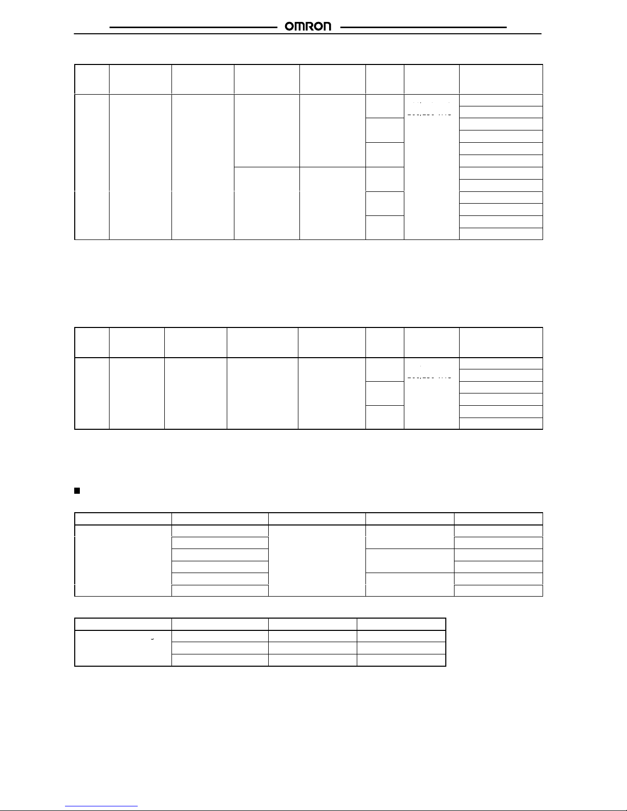
Output Characteristics
G3PX-EUN/EH/EHN
Models
Output voltage (%)
Input current (mA)
G3PX-EC
Duty Setting
G3PX-EUN/EH/EHN
Models
Output voltage (%)
Input current (mA)
100%
60%
40%
20%
Output voltage (%)
Input current (mA)
Base-up Characteristics
G3PX-2j0EUN
Models
Output voltage (%)
Input current (mA)
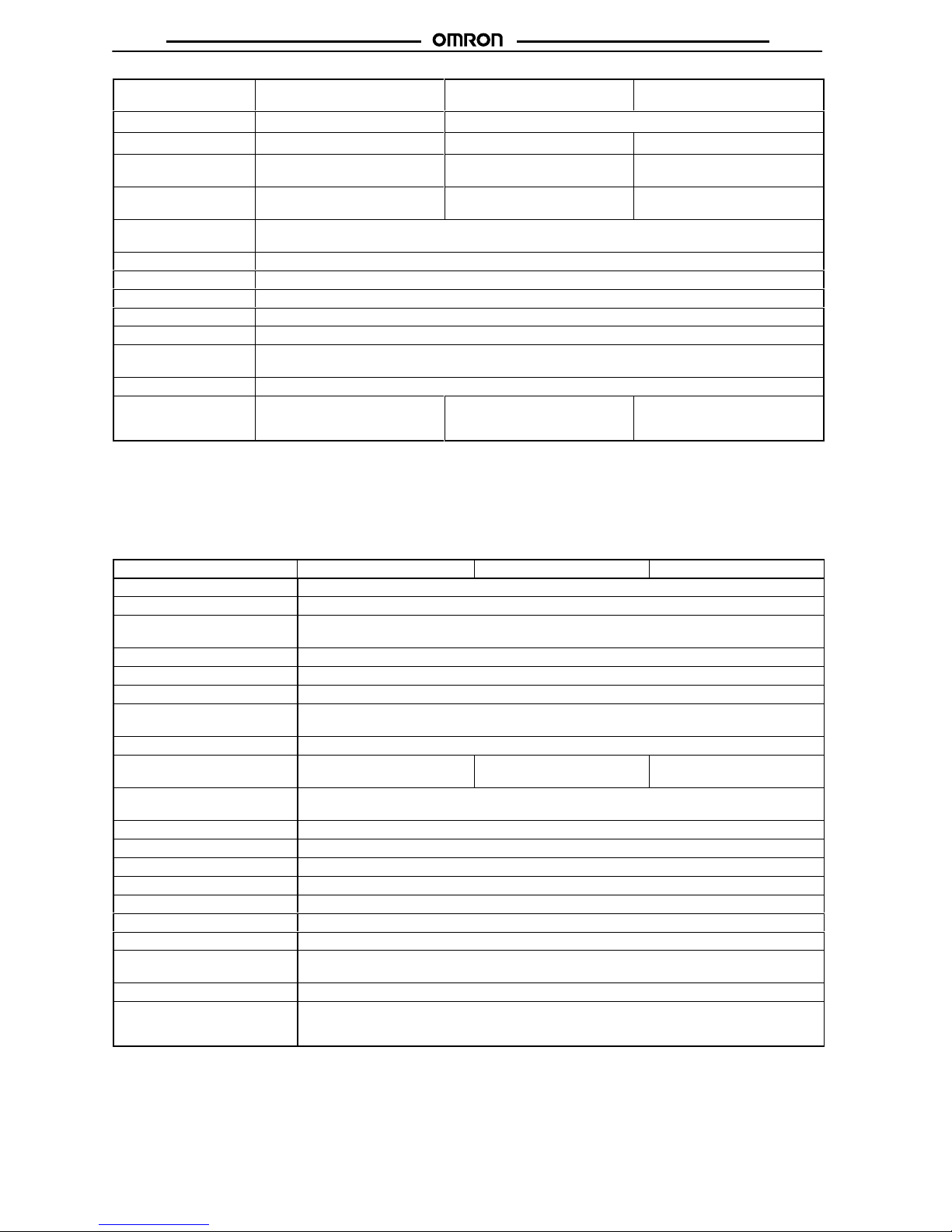
Load current (A)
Load Current vs. Ambient Temperature
G3PX-220Ej
Models
Ambient temperature (
°C)
G3PX-240Ej
Models
G3PX-260Ej
Models
Ambient temperature (
°C)
Ambient temperature (
°C)
Load current (A)
Load current (A)
Page 6
G3PX
G3PX
6
Inrush current (A.Peak)
Inrush current (A.Peak)
Inrush current (A.Peak)
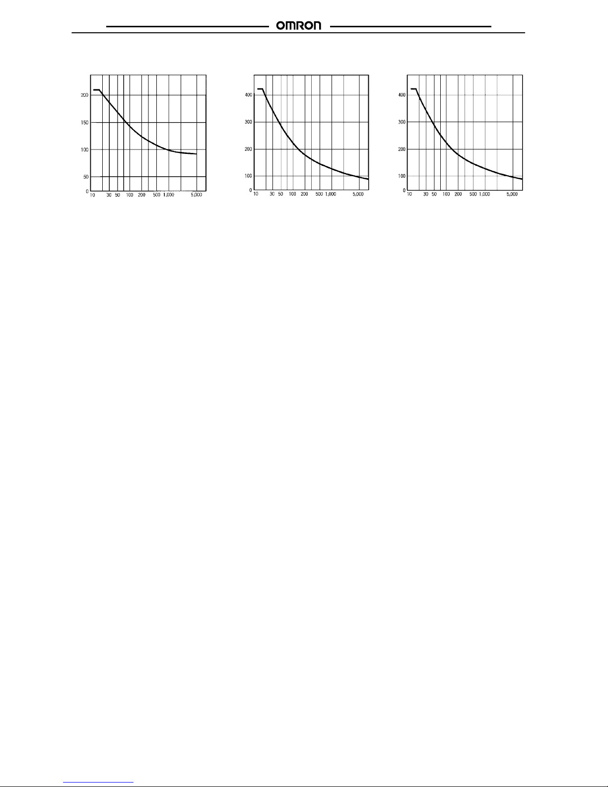
Withstand Inrush Current
G3PX-220Ej
Models
Energizing time (ms)
G3PX-240Ej
Models
G3PX-260Ej
Models
Energizing time (ms) Energizing time (ms)
Note: The
above are possible on condition that the G3PX is in non-repetitive operation. If the G3PX is in repetitive operation, reduce the
applied
current to half.
Page 7

G3PX
G3PX
7
Nomenclature
Single-function Model
(EUN-series Model)
G3PX-2j0EUN
POWER
indicator
BASE-UP adjuster
DUTY adjuster
(for internal slope
setting)
TIME adjuster
(for Extended
soft-start time)
Power Device
Cartridge
Level indicator
Single Heater Burnout Detection
(EH-series Model)
G3PX-2j0EH-CTjj
Level
indicator
POWER indicator
SHOR
T indicator
(for short-mode
failure detection)
CT Unit
OPEN indicator
(for single heater
burnout detection)
DUTY adjuster
(for internal slope
setting)
TIME adjuster
(for soft-start
time)
Reset
switch
Power
Device
Cartridge
Multiple Heater Burnout Detection
(EHN-series Model)
G3PX-2j0EHN-CTjj
Power Device
Cartridge
POWER indicator
Level indicator
SHOR
T indicator
(for short-mode
failure detection)
CT Unit
OPEN indicator
(for multiple heater
burnout detection)
DUTY adjuster
(for internal slope
setting)
TIME adjuster
(for extended soft-start
time)
RUN/SET switch for setting condition
for multiple heater burnout detection.
RESET switch
ALARM adjuster
(for multiple heater
burnout detection)
Constant-current Model
(EC-series Model)
G3PX-2j0EC-CTjj
POWER
indicator
CT Unit
CURRENT limit adjuster
(for limiting current)
TIME adjuster (for
extended soft-start
time)
Level indicator
RESET
switch
Power
Device
Cartridge
SHOR
T indicator
(for short-mode
failure detection)
OPEN indicator (for single
heater burnout detection)
DUTY adjuster
(for internal slope
setting)
Page 8
G3PX
G3PX
8
Operation
Error Detecting Function
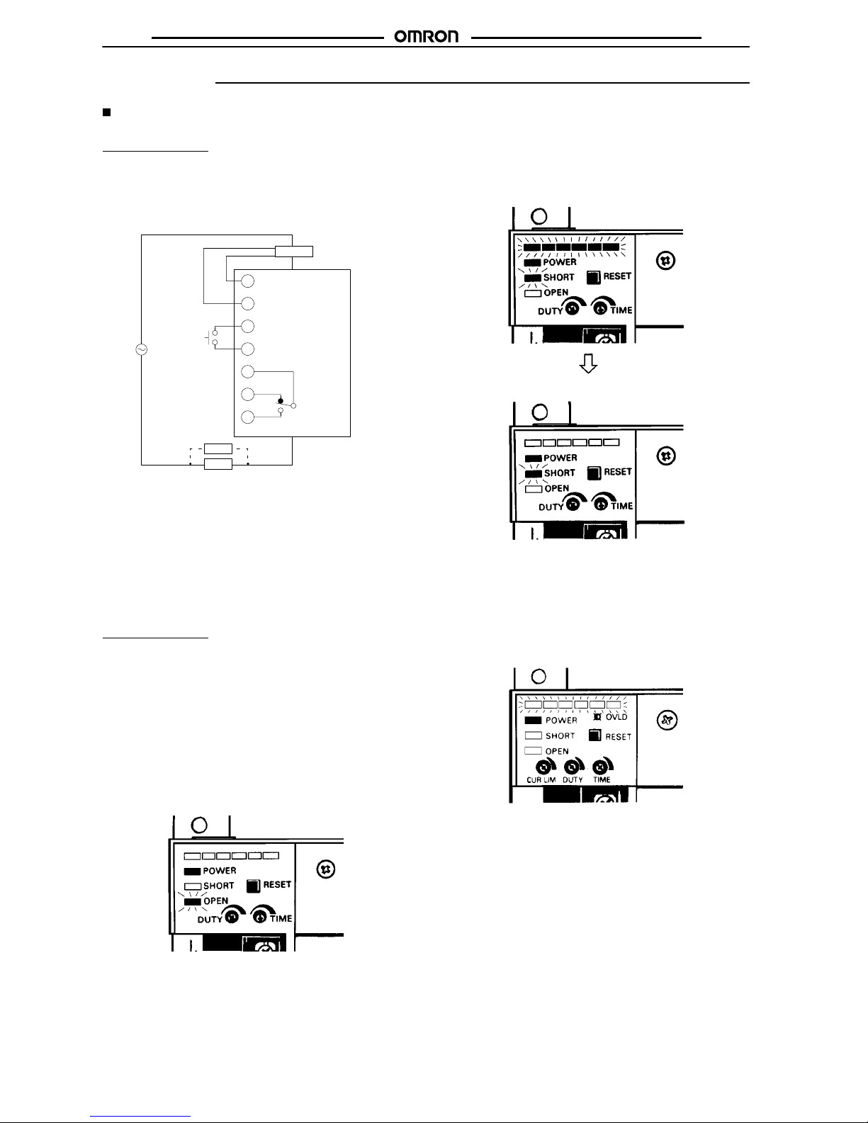
Wiring
Single-phase
Models
All
G3PX-2j0EH/EHN/EC-series models incorporate terminals 11
and
12 for the CT Unit, 13 and 14 for the external reset switch, and
16
and 17 for relay output as well as power/input terminals 1 through
10.
Note: 1. Connect
either the black or white lead wire of the CT
Unit
to
terminal 1
1 and the other lead wire to terminal
12.
The G3PX will malfunction
if you do not connect
the CT Unit to the G3PX.
2. The
rated current and voltage of
G3PX models when
reset
are as follows:
EH-series models: 12 mA at 12 VDC
EHN- and EC-series models: 1 mA at 12 VDC
3.
For more than one heater
.
11
12
13
14
15
16
17
Load
1
Load 2
G3PX-2j0EH
Load
CT Unit
External reset
switch
CT Unit
G32X-CTjj
Relay output
(SPDT)
(see note 1)
(see note 2)
(see note 3)
Load
Output
Single-phase
Models
The
following illustrations show the condition of the G3PX LED indi
cators when the G3PX detects heater burnout, a short-mode failure
(ON failure of components), or overcurrent (EC-series constant-current models only). The indicator and relay output signals
are
reset with the internal or external reset switch provided that the
error
condition has been remedied.
1. When EH/EHN/EC-series models detect single or multiple
heater
burnout, the OPEN indicator is lit and the SPDT relay
output is ON.
Note: When
the G3PX detects heater burnout, the Level indicator
will
be OFF regardless of the G3PX input condition. The red
OPEN indicator will be lit. EHN-series models, however,
will
continue operating with level indication.
2. When EH/EHN/EC-series models detect a short-mode
failure,
the SHOR
T indicator is lit and the SPDT relay output
is
ON.
With
continuous load current.
With load current shut of
f.
Note:
When the
G3PX detects a short-mode failure, all LEDs of
the
Level indicator and red SHOR
T indicator are lit. When
you
use a breaker to disconnect the load with
the relay out
-
put,
all LEDs of the Level indicator will be OFF regardless
of
the
input to the G3PX.
3. When EC-series models detect an overcurrent, the Level
indicator
will flash and the SPDT relay output is
ON. The input
signal
will be shut of
f.
Note: When
resetting, leave power supply terminals 10 to 9 or 8
ON.
Page 9

G3PX
G3PX
9
Wiring
Main Circuit
Single-phase
Models
The following illustrations show connection examples:
Note: Use
a single power supply for
the G3PX and the load.
Load
1
Load 2
G3PX
Load
1
2
3
4
5
6
7
8
9
10
200/230 VAC
100/110 VAC
Setting Circuit
Analog Control
Single-phase Models
1.
A T
emperature Controller with 4- to 20-mA output is used to control the G3PX.
1
2
3
4
5
6
7
8
9
10
Load
1
Load 2
G3PX
4 to 20 mA
4 to 20 mA
(250 Ω*)
4
5
G3PX
4
5
(250 Ω*)
G3PX
(600 Ω*)
+
–
Temperature
Controller
+
–
E5jX Temperature
Controller
Note: Two
G3PX models can be connected in series to OMRON’
s single T
empera-
ture
Controller (with an internal impedance
of 600 Ω) with a current output.
*Impedance
2. A Temperature Controller with an output of 7 to 20 mA is used with the G3PX to change the duty
.
+
–
Load
1
Load 2
G3PX
4 to 20 mA
DUTY
1
2
3
4
5
6
7
8
9
10
3
2
1
E5jX Temperature
Controller
G32X-V3K External Variable
Resistor (3 kΩ) for duty setting
Note: You
can change the duty with the external or internal ramp adjuster
.
Internal DUTY
adjuster
Page 10

G3PX
G3PX
10
ON/OFF Control
Single-phase Models
1.
A T
emperature Controller is used to change the duty of G3PZ.
1
2
3
4
5
6
7
8
9
10
3
2
1
Load
1
Load 2
G3PX
5/12/24 VDC
ON/OFF
DUTY
+
–
E5jS Temperature
Controller
Internal DUTY
adjuster
G32X-V3K External
DUTY Adjuster (3 kΩ)
Note: You
can change the duty with the external or internal variable resistor
.
2.
A T
emperature Controller (with a voltage output) is used to control several G3PXs.
T
emperature Controller specifications
No. of G3PX
E5j
X: 40 mA at 12 V
20 sets
E5j
S: 20 mA at 12 V
20 sets
20 mA at 5 V
20 sets
10 mA at 5 V
20 sets
Connection Example
–+
3
5
G3PX
Temperature
controller
3
5
G3PX
3
5
G3PX
3.
A T
emperature Controller (with a relay output) is used to vary the duty of G3PX.
3
2
1
Load
1
Load 2
G3PX
1
2
3
4
5
6
7
8
9
10
DUTY
Temperature
controller
Internal DUTY
adjuster
G32X-V3K External
DUTY Adjuster (3 kΩ)
Page 11
G3PX
G3PX
11
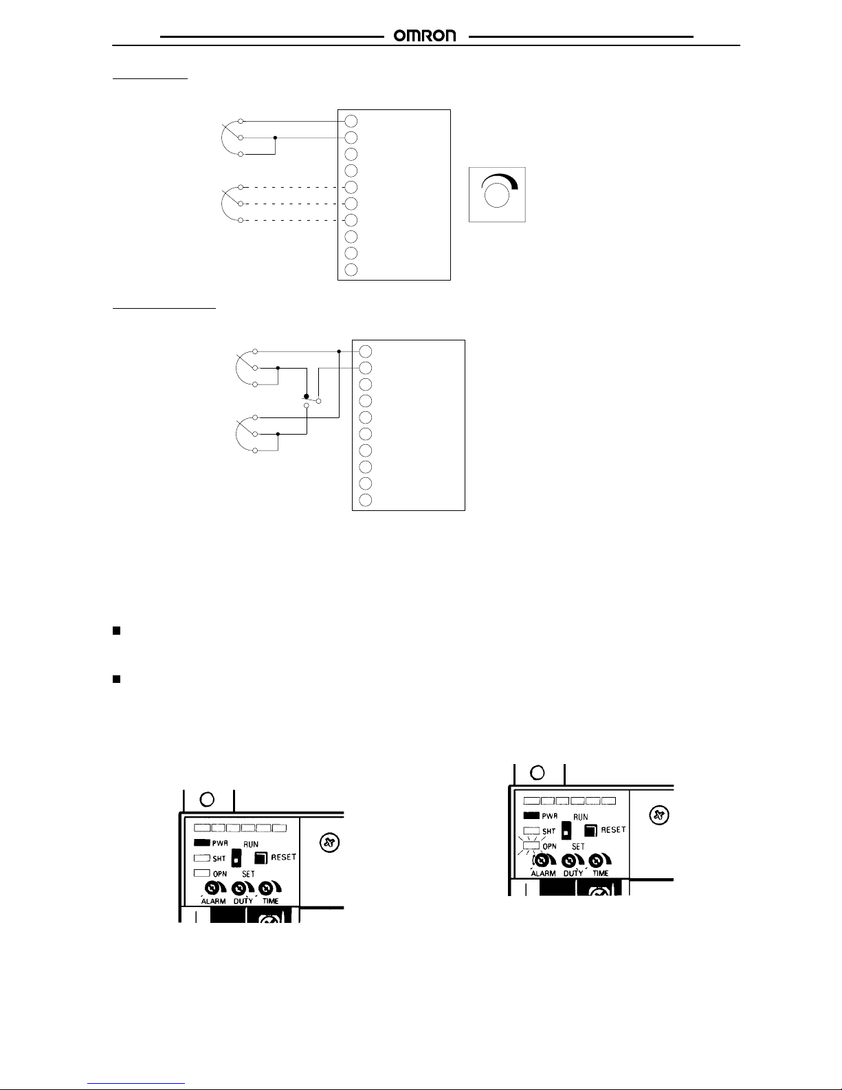
Manual Control
Single-phase Models
3
2
1
Load
1
Load 2
G3PX
DUTY
1
2
3
4
5
6
7
8
9
10
3
2
1
Internal DUTY
adjuster
G32X-V3K External DUTY
Adjuster (3 kΩ
) for duty set
-
ting
G32X-V3K or G32X-V2K
External DUTY Adjuster
Note: Delicate
duty adjustment is possi
-
ble
with
the external or internal re
sistor.
Use a right DUTY adjuster (2- or
3-kΩ
type) according to the
G3PX
model
as follows:
G32K-V3K (3 kΩ) for EH-series
models
G32X-V2K
(2 kΩ) for EUN-, EHN-,
and EC-series models
Two-position Control
Single-phase Models
Load
1
Load 2
G3PX
1
2
3
4
5
6
7
8
9
10
H (High)
L (Low)
RY
G32X-V3K or G32X-V2K
External DUTY Adjuster
Note: 1. A
temperature controller with relay output or a single relay can be used with the G3PX
in two-position (high-and low-position) control, in which case the relay contact current
is
30 mA at 12 VDC with the External DUTY Adjuster set to 0
Ω.
2. Use
a right DUTY adjuster (2- or 3-kΩ type) according to the G3PX model as follows:
G32X-V3K (3 kΩ) for EH-series models
G32X-V21K (2 kΩ) for EUN-, EHN-, and EC-series models.
Setting of Base-up Output (G3PX-2j0EUN Series)
The
base-up output can be adjusted with the base-up adjuster knob. It is also possible to control the base-up output for the
full scale of 4 to
20-mA
input current by adjusting the duty adjuster. Refer to
Engineering Data
on page
67 for the base-up characteristics.
G3PX-2j0EHN Series (Multiple Heater Burnout Detection Model)
Setting
1. Use the G32X-CTjjHN CT Unit and make sure that the
G3PX is wired correctly.
2.
The G3PX initially set is shown in the following illustration.
Make sure that the RUN/SET switch has been set to SET
.
Make
sure that the DUTY adjuster has
been turned clockwise
to
the maximum.
3.
Adjust the sensitivity
.
Turn the ALARM adjuster and set to the position where the
OPEN indicator is lit. Stop turning the ALARM adjuster as
soon
as the indicator is lit to complete the setting.
Page 12

G3PX
G3PX
12
4. Set the RUN/SET switch to RUN.
When
all settings have been finished, the OPEN indicator is
OFF.
Note: 1. The
G3PX can control any part of the phase
as long as
the controlled phase is approximately 1/6π or more in
width.
2. Be
sure to prepare terminals 18 and 19 corresponding
to
the supply frequency of 50 Hz or 60 Hz. Otherwise, a
setting
error will result in a malfunction regardless of the
RUN/SET
switch setting.
When
the error has occurred, turn the ALARM adjuster
counterclockwise to the minimum setting, reset the
G3PX,
and readjust.
Page 13

G3PX
G3PX
13
Replacement Parts
G32X-A Power Device Cartridge
The
temperature indicator will be lit in red if the power element is damaged. If the power element is damaged due to overcurrent or other rea
-
sons,
the power element and its peripheral parts can be replaced.
The power element and its peripheral parts can be replaced without disconnecting the wires of the G3PX.
Improve the heat radiation of the G3PX before replacing the Cartridge.
The temperature indicator will not be lit in red if the G3PX has overcurrent due to load short-circuiting or other reasons over a short time.
Appearance
G32X-A20 G32X-A40 G32X-A60
Replacement of G32X-A20 Power Device Cartridge
Use
the special tool (provided) to extract the
Cartridge for replace
-
ment
with a new one.
Extraction
Follow the procedures below to dismount the Power Device Cartridge
from the G3PX.
1.
Switch of
f the power
.
2.
Remove the terminal cover
.
3. Hook the tool on the indented portions of the Power Device
Cartridge as shown in the illustration below and pull up the
Power Device Cartridge vertically.
Special tool
Indented
portions
T
erminal cover
Mounting
The
procedures for mounting the Power Device Cartridge are as
fol
-
lows:
1. Apply
silicone grease (provided with the G32X-A) to the entire
surface
of the heat radiator
.
2. Make sure there is no dust or pieces of wire on the heat
radiators
of the G32X-A or the G3PX.
3. Insert
the Cartridge into the opening of the G3PX so that
the
letters on the Cartridge and those on the G3PX are in the
same
direction and sides A and B are even.
A
B
4.
Attach the terminal cover
.
5. Switch
on the power and check the G3PX to be sure it works
properly.
G32X-A40/60
The
G32X-A40 and G32X-A60 are secured with screws.
Extraction
The
procedures for dismounting the Power Device Cartridge are as
follows:
1. Switch
of
f the G3PX.
2.
Remove the terminal cover
.
3. Be
sure to turn of
f the G3PX and
loosen the screws located in
the upper center and lower center. These screws are
connected
to terminals 1 and 2.
Loosen
Loosen
Page 14

G3PX
G3PX
14
4.
Loosen the screws on both corners.
Loosen
Loosen
5. Hold the indented part of both corners to dismount the
Cartridge.
Mounting
1. Apply
silicone grease (provided with the G32X-A) to the entire
surface
of the heat radiator
.
2. Make sure there is no dust or pieces of wire on the heat
radiators
of the G32X-A or the G3PX.
3. Insert
the Cartridge into the opening of the G3PX so that
the
letters on the Cartridge and those on the G3PX are in the
same
direction and sides A and B are even.
A
B
4. Tighten
the screws on both corners
with a tightening torque of
0.59
to 0.78 N S m.
5. Tighten the center screws of the G3PX with a tightening
torque
of 0.59 to 0.78 N S m.
6.
Attach the terminal cover
.
7. Switch
on the power and check the G3PX to be sure it works
properly.
External Variable Resistor
The
G32X-V3K and G32X-V2K are provided with a set consisting of
adjuster,
knob, and nameplate.
Resistive value
(see note 1)
Model
3 kΩ
G32X-V3K (see note 2)
2 kΩ G32X-V2K
Note: 1. The G32X-V3K is equivalent to the conventional
G32X-VR.
2. Resistive
V
alue
The resistance is
read on the back of
the variable resistor.
External DUTY Adjuster Knob
Mounting Holes
Nameplate
2.5±1
31±1 dia.
15 min.
17 max.
10±1
20±1
1.6±0.2
R26 max.
1±0.1
M9P0.75
2.8±0.2 dia.
12±0.2
30 max.
6 dia.
0
–0.1
Filled with
white resin
17
14
6.5
1.6
13.4
26
34
3 dia. hole
12±0.2
9.5 dia. hole
G32X-VR
100
%
48
48
Page 15
G3PX
G3PX
15
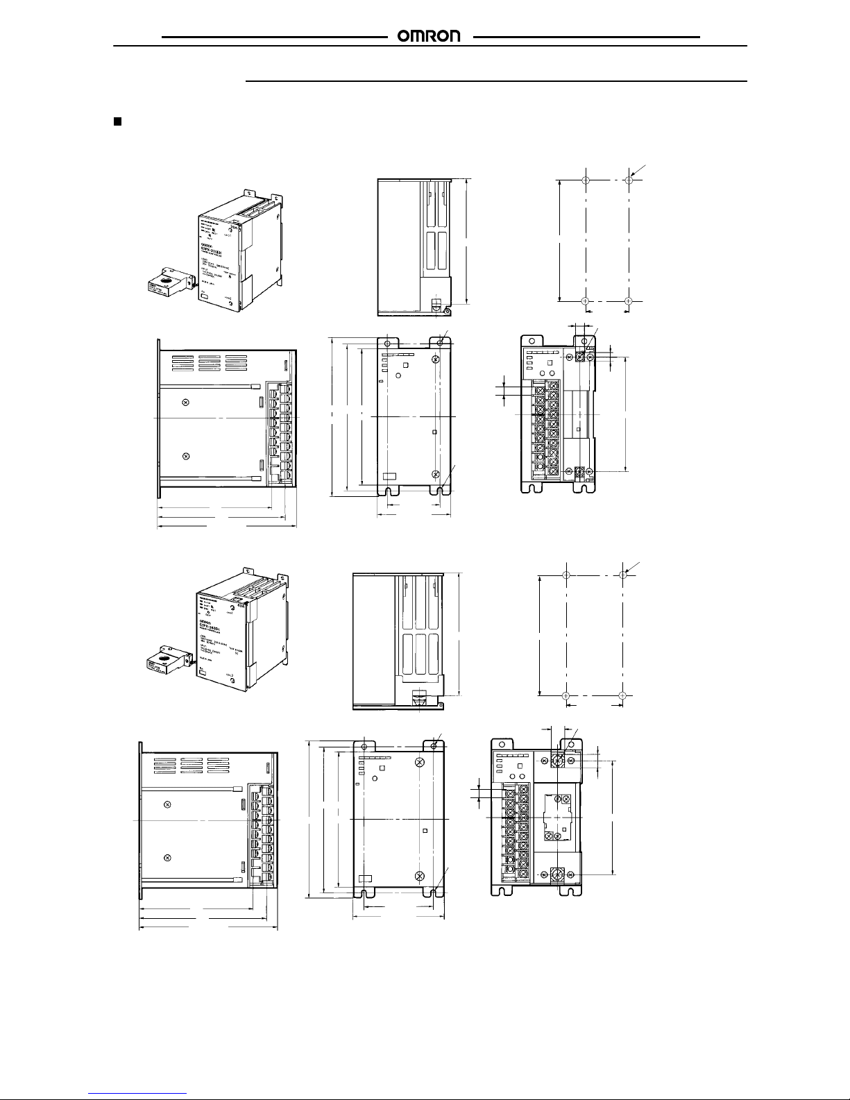
Dimensions
Note: All
units are in millimeters unless otherwise indicated.
Single-phase Models
G3PX-220Ej
Series
G3PX-240Ej
Series
Mounting
Holes
Four, 4.5 dia.
or M4 holes
140±0.3
65±0.3
119
108
120
109.8
8.6
8.6
Two, M4 screws
Two, 4.6 dia.
holes
140±0.2
50±0.2
70 max.
130 max.
Two, R2.3
holes
130
150 max.
119
108
120
13
13
109.8
130 max.
140±0.2
65±0.2
85 max.
Two, R2.3
holes
Two, M5 screws
Two, 4.6 dia.
holes
150 max.
130
Four, 4.5 dia.
or M4 holes
140±0.3
50±0.3
Mounting
Holes
7.6
7.6
Page 16

G3PX
G3PX
16
G3PX-260Ej
Series
Mounting
Holes
140±0.3
80±0.3
Four 4.5-dia. or
M4 holes
114
108
120
17
17
Two, 4.6 dia.
holes
Two,
R2.3
holes
130 max.
150 max.
140±0.2
Two, M6 screws
130
109.8
80±0.2
100 max.
7.6
G32X-CT03j
Series
G32X-CT10j
Series
Mounting
Holes
Note: 1.
Color of the hole
EH Series: Black
EHN Series: White
EC Series:
Light gray
The size of the hole of CT Units for EC- and EHN-series models is 15 dia.
2. The
G32X-CT03j incorporates 30-cm solderless terminals and the G32X-CT10
j
incorporates
100-cm solderless terminals.
50±0.2
Two 4.5-dia. or M4 holes
50
30
9.5
24
35
14
55
40
17 dia. hole
(15 dia., see
note 1)
60 max.
(see note 2)
17
Page 17

G3PX
G3PX
17
Installation
Terminal Arrangement
Single-phase
Models
G3PX-220EUN
G3PX-240EUN
G3PX-260EUN
G3PX-220EH
G3PX-240EH
G3PX-260EH
1
Voltage ON/OFF input
VOLTAGE IN
2
3
4
5
6
7
8
9
10
External main setting
3 kΩB 2 W
MAN SET
(1 to 5 VDC)
(Voltage)
5 to 24 VDC
INPUT
External duty setting
3 kΩB
MAN DUTY SET
200/230 VAC
50/60 Hz
100/110 VAC
50/60 Hz
SOURCE
Current input
4 to 20 mA DC CURRENT
1
2
3
4
5
6
7
8
9
10
Voltage ON/OFF input
VOLTAGE IN
External main setting
3 kΩB 2 W
MAN SET
(1 to 5 VDC)
(VOLTAGE)
5 to 24 VDC
INPUT
External duty setting 3 kΩB
MAN DUTY SET
200/230 VAC
50/60 Hz
100/110 VAC
50/60 Hz
SOURCE
Current input
4 to 20 mA DC CURRENT
11
12
13
14
15
16
17
RESET
CT UNIT
G32X-CT
W
B
ALARM
Internal contact
configuration
2 kΩ
B, 2 W for
EUN-series models
G3PX-220EHN/220EC
G3PX-240EHN/240EC
G3PX-260EHN/260EC
1
2
3
4
5
6
7
8
9
10
11
12
13
14
15
16
17
Voltage ON/OFF input
VOLTAGE IN
External main setting
2 kΩB 2 W
MAN SET
(1 to 5 VDC)
(VOLTAGE)
5 to 24 VDC
INPUT
External duty setting
3 kΩB
MAN DUTY SET
200/230 VAC
50/60 Hz
100/110 VAC
50/60 Hz
SOURCE
Current input
4 to 20 mA DC CURRENT
RESET
CT UNIT
G32X-CT
W
B
ALARM
Internal
contact
configuration
18
19
OPEN 50 Hz
SHORT 60 Hz
(see note)
Note: Open
the terminals for 50 Hz or short-circuit the terminals for 60 Hz. When the product is shipped, the terminals are short-circuited
using a short-circuiting bar to set to 60 Hz. When using at 50 Hz, remove the short-circuiting bar
.
Page 18

G3PX
G3PX
18
Precautions
Correct Use
Load
Only resistive loads can be connected to the G3PX. Contact your
OMRON representatives if it is necessary to connect inductive or
transformer
loads.
Mounting
The three-phase, 60-A G3PX weighs approximately 5 kg. Pay utmost
attention when mounting the G3PX so that the
G3PX will not
fall
thus resulting in injury
.
V
ertical Mounting
Note: In
the
case of flat mounting, the 30% derating of the
load
current is required.
Flat Mounting
Note: Make sure that there is a space of at least 50 mm
vertically
and at
least 10 mm horizontally between
adjacent
single-phase models.
10 mm10 mm
50 mm
10 mm 10 mm
Close Mounting Example (Single-phase Models)
Wiring
Make
sure that the lead wires are thick
enough according to the cur
-
rent.
Be
sure to turn of
f power to the G3PX when wiring. The G3PX has
current
leakage although the G3PX is turned of
f if the power
supply
is
connected to the G3PX, which may give an electric shock.
Do
not wire power lines or high-tension lines along with the lines of
the G3PX in the same conduit, otherwise the G3PX may be damaged
or malfunction due to induction. Be sure to wire the lines of the
G3PX
separated from power lines or high-tension lines or laid in an
exclusive,
shielded conduit.
Tightening Torque
Apply
the following tightening torque.
Output terminal:
20-A model: 1.47 N S m
40-A model: 2.45 N S m
60-A model: 4.12 N S m
T
erminal block:
Single-phase model: 0.98 N S m
Be
sure to protect the terminals with the protective cover after wir
-
ing.
Wiring for Error Detection
If
a contactor is employed and operated with the relay output signal
of
the G3PX for error detection, make sure that the G3PX is closer to
the
power supply than the contactor
.
Instruments
Instrument Remarks
Thermal type
Available
Digital type displaying
root-mean-square values
Moving-iron type
Rectifier type
Not available (not
Multimeter
oaaabe(o
precise enough)
Digital multimeter
The
instruments are used for displaying room-mean-square voltage
and current values of the AC circuitry.
Operation Monitoring
The
level indicator just indicates the phase of the load and it is not
highly precise.
Ramp Setting
There
is a decrease in ramp if the internal DUTY adjuster is turned
counterclockwise.
100% 10%
DUTY DUTY
If the External DUTY Adjuster is used, set the Internal DUTY
Adjuster
to 100%.
CT Unit
The
CT Unit varies with the G3PX-series model. Use the following
CT
Units in combination with the G3PX models.
G3PX-2j0EH Series: G32X-CTjj
G3PX-2j0EHN Series: G32X-CTjjHN
G3PX-2j0EC Series: G32X-CTjjC
Page 19

G3PX
G3PX
19
If
any of the following models is used and the actual load current is
50%
of the maximum rated load current or lower
, increase the num
-
ber
of turns of the wire around the CT Unit.
G3PX-20EHN Series (multi-heater burnout detective models)
G3PX-20EC Series (constant current)
For
example, make two turns if the actual load current is 50% of the
maximum
rated load current and four turns if the actual load current
is
25% of the maximum rated load current.
If
the G3PX is a constant current model, do not increase the number
of turns of the wire around the CT Unit excessively, otherwise the
overcurrent
detective function may operate by mistake.
External DUTY Adjuster
Use the External DUTY Adjuster with a resistance of 2 kΩ or that
with a resistance of 3 kΩ according to the G3PX-series model in
use.
Refer to the following combinations.
G3PX-2jEH Series: G32X-V3K (3 kΩ)
G3PX-2j0EUN Series
G3PX-2j0EC Series
Base-up Function
If
the model in use has the model
number suf
fix “EUN,” the base-up
function
is available.
The
base-up output of the G3PX with a temperature controller out
-
put
of 0 mA (i.e., the temperature controller is
turned of
f) and that of
the
G3PX with a temperature controller output of 4
mA are dif
ferent
from
each other
.
Power Device Cartridge
Do not apply power to the G3PX with the Power Device Cartridge
dismounted.
Heater Burnout Detection
EH
and EHN Models
The
heater burnout
detective function is not available for detecting
the
phase less than the following.
G3PX-20EH Series: π/8 or less
G3PX-20EHN Series: Approx. π/6 or less
Phase not detectable
Power Supply
Single-phase
Models Only
Do not apply 200 V to the 100-V terminals, otherwise the thermal
fuse
of the built-in transformer will be blown
and the G3PX will not
operate.
Others
It
is not possible to use
three single-phase models for three-phase
load
control.
If
three-phase power supply is used for single-phase models oper
-
ating in parallel, make sure that the two
phases supplied to all the
single-phase models are the same.
Troubleshooting
Check
the following if the G3PX does not operate or has dif
ficulty in
temperature
control.
•
The load does not turn on with 100% input.
Check the default internal ramp setting.
DUTY
Make sure that the adjuster is set to the farthest
clockwise position.
Also check
the current limit adjuster if the G3PX is a constant DC
model.
CUR LIM
• The
G3PX does not operate or is in abnormal operation.
Make
sure that all input terminals are connected properly with no
mistakes
in polarity
.
Make
sure that the internal DUTY adjuster is not set to the farthest
clockwise
position.
Make
sure that the frequency used by the G3PX (i.e., 50 or 60 Hz)
is
set properly
. (This applies to the EC, and EHN models.)
•
The G3PX malfunctions if the external adjusters are turned.
Make sure that the numbers on the external adjusters coincide
with
the corresponding terminal numbers on the G3PX.
Make
sure that the 2-kΩ and 3-kΩ DUTY
adjusters are connected
correctly.
External main setting External duty setting
(Positive)
Note: 1, 2, 3, 5, 6, and 7 are terminal
numbers
of the G3PX.
(Positive)
• Temperature control with a Voltage-output Temperature
Controller
is not smooth.
Make sure that the controlled soft-start up/down time has been
adjusted
properly
. If not, turn the
TIME adjuster counterclockwise
to the minimum setting to reduce the controlled start-up/down
time.
TIME
TIME
Input signal
Controlled
soft-start
up
Reduce this period.
Input signal
Controlled
soft-start
up
• The Level indicator is not OFF with a 0% input signal
(G3PX-2j0EUN
Series).
Make
sure that the BASE UP adjuster has been turned counter
-
clockwise
to the minimum setting.
BASE UP
Make sure that the adjuster
is turned counterclockwise
to the minimum setting.
Page 20

G3PX
G3PX
20
•
The
OPEN indicator of a multiple heater burnout detection model
is
lit at the initial stage (G3PX-2
j0EHN Series).
Make sure that the initial settings are OK. If not, readjust the
G3PX.
Make sure that terminals 18 and 19 are open if the supply frequency is 50 Hz. These terminals must be short-circuited if the
supply frequency is 60 Hz.
Make sure that the load current is large enough.
•
The Level indicator LEDs of a constant-current model are all lit
and no power control operation is possible.
Make sure that the load current is large enough.
Countermeasure
1: Adjust the CUR LIM adjuster so that the LED
on
the farthest right of the Level indicator is OFF
.
Adjust so that this LED is OFF.
CUR LIM adjuster for limiting current
Countermeasure
2: When the supply current is less than 50%, in
crease the number of turns. When the supply current is 50% of
the
rated current, the wires must be coiled twice on the CT
Unit.
When the supply current is 25% of the rated current, the wires
must
be coiled three to four times on the CT Unit.
• No
reset will be performed even if the RESET button is
pressed.
Check whether the RESET button is pressed while there is
nothing
input into to power supply terminals 8 and 10 or 9 and 10
of
the G3PX.
Be sure to press the RESET button with power supplied to the
G3PX.
The following wiring will be required if the breaker or contactor
connected
between the power supply and the G3PX is operated
by
the relay output of the G3PX.
Magnet
contactor
Load
ALL DIMENSIONS SHOWN ARE IN MILLIMETERS.
To
convert millimeters into inches, multiply by 0.03937. T
o convert grams into ounces, multiply by 0.03527.
Cat. No. K076-E1-2A
 Loading...