

Page 1
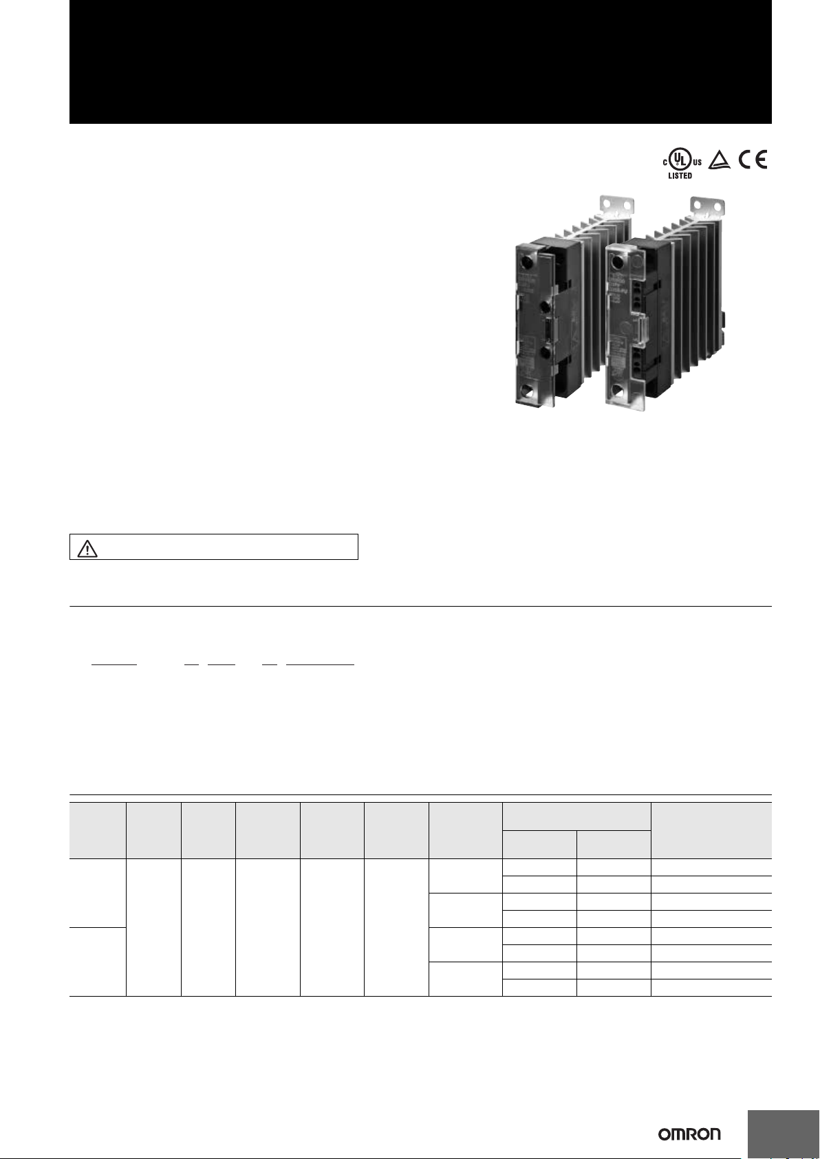
Solid State Relays for Heaters
For the recent information on models that have been certified
for safety standards, refer to your OMRON website.
Refer to Safety Precautions on page 5.
1. Rated Load Voltage
2: 24 to 240 VAC
5: 100 to 480 VAC
2. Rated Load Current for Three Close-mounted SSRs
15: 15 A
25: 25 A
3. Input Terminal Form
Blank: Screw technology
PU: Push-in plus technology
G3PJ
Single-phase SSR for low heat
generation enables carrying 25 A * even
for close mounting of three SSRs to
contribute to downsizing of control
panels.
Models available with push-in plus input
terminals.
* G3PJ-@25B(-PU)
• SCCR of 10kA (UL 508).
• Surge pass protection improved surge dielectric strength for
output currents. (OMRON testing)
• Both push in plus and screw Technology input terminals
available.
• Mount to DIN Track or with screws.
• Conforms to cULus and EN standards (TÜV certification).
• RoHS compliant.
Model Number Structure
Model Number Legend
G3PJ - @ @@B - @ DC12-24
Basic Model Name Rated input voltage12 3
Ordering Information
Rated load current (ambient
Input
terminal
Screw
terminals
Push-in
plus
technology
* The applicable load current depends on the ambient temperature. For details, refer to Load Current vs. Ambient Temperature in Engineering
Data on page 3.
Output
terminal
Screw
terminals
Insulation
method
Phototriac
coupler
Operation
indicator
Yes (orange)
Rated input
voltage
12 to 24 VDC
Zero cross
function
Yes
Rated load
voltage
24 to 240 VAC
100 to 480 VAC
24 to 240 VAC
100 to 480 VAC
temperature of 40°C) *
Close mounting
(Three SSRs)
15 A 18 A G3PJ-215B DC12-24
25 A 27 A G3PJ-225B DC12-24
15 A 23 A G3PJ-515B DC12-24
25 A 27 A G3PJ-525B DC12-24
15 A 18 A G3PJ-215B-PU DC12-24
25 A 27 A G3PJ-225B-PU DC12-24
15 A 23 A G3PJ-515B-PU DC12-24
25 A 27 A G3PJ-525B-PU DC12-24
Separate
mounting
Model
1
Page 2
G3PJ
Specifications
Ratings
Input (at an Ambient Temperature of 25°C)
Model
Item
G3PJ-2@@B(-PU)/
G3PJ-5@@B(-PU)
Rated voltage
12 to 24 VDC 9.6 to 30 VDC 7 mA max. 9.6 VDC max. 1.0 VDC min.
Output
Item
Model
G3PJ-215B(-PU)
G3PJ-225B(-PU)
G3PJ-515B(-PU)
G3PJ-525B(-PU)
* For close mounting of three SSRs.
Rated load voltage
24 to 240 VAC
100 to 480 VAC
Characteristics
50/60 Hz
50/60 Hz
Operating voltage
Load voltage
19 to 264 VAC
50/60 Hz
75 to 528 VAC
50/60 Hz
range
range
Current
Load current Inrush current resistance I2t
Close mounting *: 15 A,
Separate mounting: 18 A
Close mounting *: 25 A,
Separate mounting: 27 A
Close mounting *: 15 A,
Separate mounting: 23 A
Close mounting *: 25 A,
Separate mounting: 27 A
Must operate
voltage
150 A (60 Hz, 1 cycle) 260A2s
220 A (60 Hz, 1 cycle) 1,260A2s
150 A (60 Hz, 1 cycle) 1,350A2s
220 A (60 Hz, 1 cycle) 6,600A2s
Must release
voltage
Item
Operate time
Release time
Output ON voltage drop
Leakage current
Insulation resistance
Dielectric strength
Vibration resistance
Shock resistance
Ambient storage
temperature
Ambient operating
temperature
Ambient operating humidity
Weight
Model
1/2 of load power source cycle + 1 ms max.
1/2 of load power source cycle + 1 ms max.
1.6 V (RMS) max. 1.8 V (RMS) max.
10 mA max. (at 240 VAC) 20 mA max. (at 480 VAC)
100 M min. (at 500 VDC)
2,500 VAC 50/60 Hz for 1 min 4,000 VAC 50/60 Hz for 1 min
10 to 55 to10 Hz, 0.35 mm single amplitude (0.7 mm double amplitude) (Mounted to DIN track)
Destruction: 300 m/s2 (Mounted to DIN track)
-30 to 100°C (with no icing or condensation)
-30 to 80°C (with no icing or condensation)
45% to 85%
Applicable Standards
cULus and TÜV (EN 60947-4-3)
Pollution category 2
RoHS compliant
G3PJ-2@@B(-PU) G3PJ-5@@B(-PU)
Approx. 240 g
2
Page 3
Engineering Data
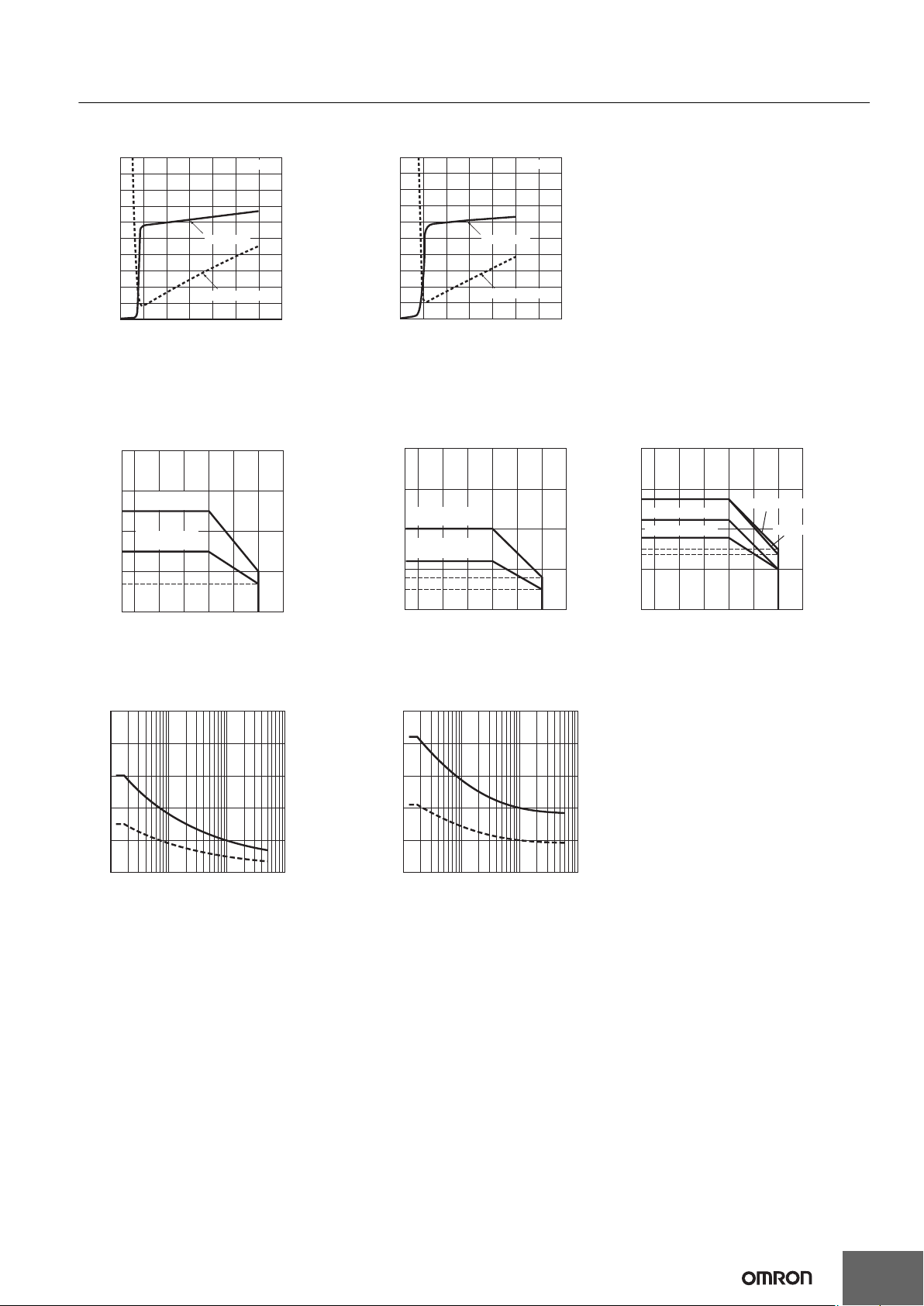
Input Voltage vs. Input Impedance and Input Voltage vs. Input Current
G3PJ-2@@B(-PU) G3PJ-5@@B(-PU)
10
9
8
7
Input current (mA)
6
Input impedance (kΩ)
5
4
3
2
1
0
0 5
10 15 20 25 30 35
Ta = 25°C
Input current
Input impedance
Input voltage (V)
Load Current vs. Ambient Temperature
G3PJ-215B(-PU), G3PJ-225B(-PU)
G3PJ-515B(-PU), G3PJ-525B(-PU)
Close Mounting of Three SSRs Close Mounting of Eight SSRs Separate Mounting
40
30
G3PJ-225B(-PU)
G3PJ-525B(-PU)
25
Load current (A)
20
G3PJ-215B(-PU)
G3PJ-515B(-PU)
15
10
7
0
−30 −20
0 20 40 60 80 100
Ambient temperature (°C)
10
9
8
7
Input current (mA)
6
Input impedance (kΩ)
5
4
3
2
1
0
40
30
Load current (A)
20
12
10
8
5
0
−30 −20
Input current
Input impedance
0 5
10 15 20 25 30 35
G3PJ-225B(-PU)
G3PJ-525B(-PU)
G3PJ-215B(-PU)
G3PJ-515B(-PU)
0 20 40 60 80 100
Ambient temperature (°C)
Ta = 25°C
Input voltage (V)
(Separated by 10 mm or More)
40
35
30
27
Load current (A)
G3PJ-515B(-PU)
23
20
G3PJ-215B(-PU)
18
15
14
10
0
−30 −20
0 20 40 60 80 100
G3PJ
G3PJ-525B(-PU)
G3PJ-225B(-PU)
Ambient temperature (°C)
Inrush Current Resistance: Non-repetitive
Keep the inrush current to below the inrush current resistance value (i.e., below the broken line) if it occurs repetitively.
G3PJ-215B(-PU), G3PJ-515B(-PU) G3PJ-225B(-PU), G3PJ-525B(-PU)
250
200
150
Inrush current (A. Peak)
100
50
0
10 30 50
100
300 500 1,000 3,000 5,000
Energized time (ms)
250
200
150
Inrush current (A. Peak)
100
50
0
10 30 50
100
300 500 1,000 3,000 5,000
Energized time (ms)
3
Page 4
G3PJ
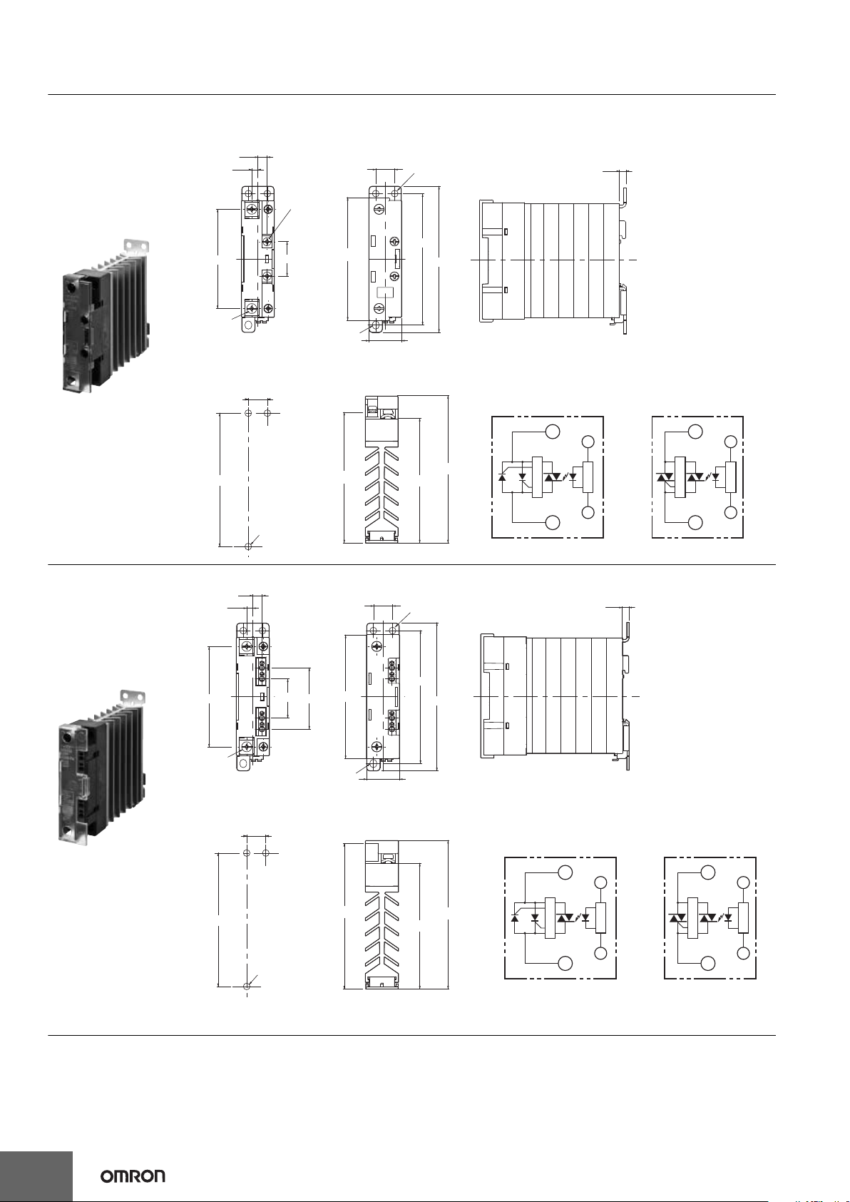
SSRs with Screw Terminals
G3PJ-215B
G3PJ-225B
G3PJ-515B
G3PJ-525B
Two , M 4
68
4.2
6.3
Two ,
M3.5
Note: Without terminal cover.
24
13
±0.2
Two ,
4.6 dia.
100 max.
90
±0.2
84
22.5 max.
4.6 × 5.6
Oval hole
Note: With terminal cover.
4.5
90
±0.3
Three, 4.5 dia.
or M4
Mounting Holes
13
±0.3
(90)
(85)
(100)
1
2
A1
A2
(+)
(−)
G3PJ-5@@B
1
2
A1
A2
(+)
(−)
G3PJ-2@@B
Terminal Arrangement/Internal Circuit Diagram
Output side
tiucric reggirT
Input side
Input side
Output side
ti
u
c
r
ic reggi
rT
t
iu
cr
i
c t
u
pn
I
ti
u
cr
ic
t
u
pn
I
SSRs with push-in plus
technology
G3PJ-215B-PU
G3PJ-225B-PU
G3PJ-515B-PU
G3PJ-525B-PU
Dimensions (Unit: mm)
Solid State Relays
4
6.1
4.2
26.5
68
2-M4
Note: Without terminal cover.
Mounting Holes
±0.3
13
90
±0.3
Three, 4.5 dia.
or M4
41.5
4.6 × 5.6
Oval hole
Note: With terminal cover.
(98.5)
±0.2
13
Two ,
4.6 dia.
±0.2
84
22.5 max.
90
100 max.
4.5
Terminal Arrangement/Internal Circuit Diagram
(85)
(100)
G3PJ-5@@B-PU
Output side
1
Trigger circuit
2
(+)
A1
Input circuit
A2
(−)
Input side
Output side
G3PJ-2@@B-PU
1
Trigger circuit
2
(+)
A1
Input circuit
A2
(−)
Input side
Page 5

Safety Precautions
Be sure to read the Safety Precautions for All Solid State Relays in the website at the following URL:
http://www.ia.omron.com/.
Format of Warning Indications
Indicates a potentially hazardous situation
CAUTION
Precautions for
Safe Use
Precautions for
Correct Use
which, if not avoided, may result in minor or
moderate injury or in property damage.
Indicates supplementary comments on
what to do or avoid doing, to use the
product safety.
Includes operating precautions to ensure
that the product will operate properly and
that performance and functions will not be
adversely affected.
Meaning of Graphic Symbols for Ensuring Product Safety
Indicates the possibility of electric shock under
specific conditions.
Indicates the possibility of explosion under specific
conditions.
Indicates the possibility of injuries by high
temperature under specific conditions.
CAUTION
Minor electrical shock may occasionally occur.
Do not touch the G3PJ terminal section (i.e., currentcarrying parts) while the power is being supplied.
Also, always attach the cover terminal.
The G3PJ may rupture if short-circuit current flows. As
protection against accidents due to short-circuiting,
be sure to install protective devices, such as fuses
and no-fuse breakers, on the power supply side.
Minor electrical shock may occasionally occur.
Do not touch the main circuit terminals on the G3PJ
immediately after the power supply has been turned
OFF. Shock may result due to the electrical charge
stored in the built-in snubber circuit.
Minor burns may occasionally occur.
Do not touch the G3PJ or the heat sink while the
power is being supplied or immediately after the
power supply has been turned OFF. The G3PJ and
heat sink become extremely hot.
OMRON constantly strives to improve quality and reliability.
The G3PJ, however, use semiconductors, and semiconductors may
commonly malfunction or fail. In particular, it may not be possible to
ensure safety if the G3PJ are used outside the rated ranges.
Therefore, always use the SSRs within the ratings. When using the
G3PJ, always design the system to ensure safety and prevent human
accidents, fires, and social harm in the event of the G3PJ failure.
System design must include measures such as system redundancy,
measures to prevent fires from spreading, and designs to prevent
malfunction.
Transport
Do not transport the G3PJ under the following conditions.
Doing so may result in damage, malfunction, or deterioration of
performance characteristics.
• Conditions in which the G3PJ may be subject to water.
• Conditions in which the G3PJ may be subject to high temperature
or high humidity.
• Conditions in which the G3PJ is not packaged.
• Do not drop the G3PJ or subject it to abnormal vibration or shock
during transportation or mounting. Doing so may result in
deterioration of performance, malfunction, or failure.
Operating and Storage Environments
Do not use or store the G3PJ in the following locations. Doing so may
result in damage, malfunction, or deterioration of performance
characteristics.
• Locations subject to rainwater or water splashes.
• Locations subject to exposure to water, oil, or chemicals.
• Locations subject to high temperature or high humidity.
• Do not store in locations subject to ambient storage temperatures
outside the range 30 to 100C.
• Locations subject to relative humidity outside the range 35% to
85% or locations in which condensation may occur due to rapid
changes in temperature.
• Locations subject to corrosive gases.
• Locations subject to dust (especially iron dust) or salts.
• Locations subject to direct sunlight.
• Locations subject to shock or vibration.
• Do not allow solvents such as thinners or gasoline to come into
contact with the plastic parts of the G3PJ. A solvent may erase the
markings.
• Do not allow oil to come into contact with the terminal cover on the
G3PJ. The cover may become milky or crack.
Installation and Handling
• Do not block the movement of the air surrounding the G3PJ or heat
sink. Abnormal heating of the G3PJ may result in shorting failures
of the output elements or burn damage.
• Do not use the G3PJ if the heat radiation fins have been bent by
being dropped. Doing so may result in malfunction due to a
reduction in the heat radiation performance.
• Do not handle the G3PJ with oily or dusty (especially iron dust)
hands. Doing so may result in malfunction.
Precautions for Safe Use
G3PJ
5
Page 6

G3PJ
Installation and Mounting
• Mount the G3PJ in the specified direction. (Refer to Mounting on
page 7.) Excessive heat generated by the G3PJ may cause shortcircuit failures of the output elements or burn damage.
• Make sure that there is no excess ambient temperature rise due to
the heat generation of the G3PJ. If the G3PJ is mounted inside a
panel, install a fan so that the interior of the panel is fully ventilated.
• Make sure the DIN track is securely mounted. Otherwise, the G3PJ
may fall.
• When mounting the heat sink, do not allow any foreign matter
between the heat sink and the mounting surface. Foreign matter
may cause malfunction due to a reduction in the heat radiation
performance.
• If the G3PJ is mounted directly in a control panel, use aluminum,
steel plating, or similar material with a low heat resistance as a
substitute for a heat sink. Using the G3PJ mounted in wood or
other material with a high heat resistance may result in fire or
burning due to heat generated by the G3PJ.
• The G3PJ is heavy. Firmly mount the DIN track and secure both
ends with End Plates for DIN-track-mounting models. When
mounting the G3PJ directly to a panel, firmly secure it to the panel.
Installation and Wiring
• Use wires that are suited to the load current. Otherwise, excessive
heat generated by the wires may cause burning.
• Do not use wires with a damaged outer covering.
Otherwise, it may result in electric shock or ground leakage.
• Do not wire any wiring in the same duct or conduit as power or
high-tension lines. Otherwise, inductive noise may damage the
G3PJ or cause it to malfunction.
• When tightening terminal screws, prevent any non-conducting
material from becoming caught between the screws and the
tightening surface. Otherwise, excessive heat generated by the
terminal may cause burning.
• Do not use the G3PJ with loose terminal screws. Otherwise,
excessive heat generated by the wire may cause burning.
• Use suitable wire lengths for wiring. Inductive noise may
occasionally cause malfunction, failure, or burn damage.
• Always turn OFF the power supply before performing wiring. Not
doing so may cause electrical shock.
Push-in plus technology
• Do not wire anything to the release holes.
• Do not tilt or twist a flat-blade screwdriver while it is inserted into a
release hole on the terminal. The terminal may be damaged.
• Insert a flat-blade screwdriver into the release holes at an angle.
The terminal may be damaged if you insert the screwdriver straight
in.
• Do not allow the flat-blade screwdriver to fall out while it is inserted
into a release hole.
• Do not bend a wire past its natural bending radius or pull on it with
excessive force. Doing so may cause the wire disconnection.
• Do not insert more than one wire into each terminal insertion hole.
• To prevent wiring materials from smoking or ignition, use the wiring
materials given in the following table.
Recommended Wire
0.25 to 1.5 mm2 / AWG24 to AWG16 10 mm 8 mm
Note: Please use Ferrules with UL certification (R/C).
Stripping length
With Ferrules
Without Ferrules
Installation and Usage
• Do not apply a voltage or current that exceeds the rating to any
terminal. Doing so may result in malfunction or burn damage.
• Select a load within the rated values. Not doing so may result in
malfunction, failure, or burning.
• Select a power supply within the rated frequencies. Not doing so
may result in malfunction, failure, or burning.
• If a surge voltage is applied to the load of the Contactor, a surge
bypass(*) will function to trigger the output element. The G3PJ
therefore cannot be used for motor loads. Doing so may result in
load motor malfunction.
* Surge Bypass
This circuit protects the output circuit from being destroyed. This
suppresses the surge energy applied inside the SSR in comparison
with a varistor for the main circuit protection. By alleviating electrical
stress on the electronic components of the SSR's output circuit,
failure and destruction due to surge voltage are suppressed.
Reference value: Surge dielectric strength of 30 kV min.
(Test conditions: 1.2 ✕ 50 s standard voltage waveform, peak voltage
of 30 kV, repeated 50 times according to JIS C5442)
Precautions for Correct Use
The G3PJ in operation may cause an unexpected accident.
Therefore it is necessary to test the G3PJ under the variety of
conditions that are possible. As for the characteristics of the G3PJ, it
is necessary to consider differences in characteristics between
individual G3PJ.
The ratings in this catalog are tested values in a temperature range
between 15C and 30C, a relative humidity range between 25% and
85%, and an atmospheric pressure range between 86 and 106 kPa.
It will be necessary to provide the above conditions as well as the load
conditions if the user wants to confirm the ratings of specific SSRs.
Causes of Failure
• Tighten each terminal to the torque specified below. Improper
tightening may result in abnormal heat generation at the terminal,
which may cause burning.
Terminals Screw terminal diameter Tightening torque
Input terminals M3.5 0.59 to 1.18 N·m
Output
terminals
• Do not supply overvoltage to the input circuits or output circuits.
Doing so may result in failure or burning.
• Do not use or store the G3PJ in the following conditions. Doing so
may result in deterioration of performance.
Locations subject to static electricity or noise
Locations subject to strong electric or magnetic fields
Locations subject to radioactivity
M4 0.98 to 1.47 N·m
6
Page 7

G3PJ
Output Terminal Section
Input Terminal Section
Release hole
Terminal (Insertion) hole
Ferrule
Mounting
• The G3PJ is heavy. Firmly mount the DIN Track and secure both
ends with End Plates for DIN Track mounting models. When
mounting the G3PJ directly to a panel, firmly secure it to the panel.
Screw diameter: M4
Tightening torque: 0.98 to 1.47 N·m
Mounted on a
Vertical
Direction
vertical surface
Panel
Mounted on a
horizontal surface
Panel
Note: Make sure that the load current is 50% of the rated load current
when the G3PJ is mounted horizontally.
For details on close mounting, refer to the related information
under performance characteristics.
Mount the G3PJ in a direction so that the markings read
naturally.
Wiring
• When using crimp terminals, refer to the terminal clearances
shown below.
15-A and 25-A Models
10 mm
12.4 mm
M4 (15 A, 25 A)
Screw Terminals Push-in Terminals
7.0 mm
Push-in plus technology
1. Connecting Wires to the Push-in plus technology
Part Names of the technology
Release hole
Terminal (Insertion) hole
Connecting Wires with Ferrules and Solid Wires
Insert the solid wire or ferrule straight into the terminal until the end
strikes the terminal.
If a wire is difficult to connect because it is too thin, use a flat-blade
screwdriver in the same way as when connecting stranded wire.
Connecting Stranded Wires
Use the following procedure to connect the wires to the terminal.
1. Hold a flat-blade screwdriver at an angle and insert it into the
release hole.
The angle should be between 10° and 15°. If the flat-blade
screwdriver is inserted correctly, you will feel the spring in the
release hole respond.
Release hole
Flat-blade screwdriver
1
• Make sure that all lead wires are thick enough for the current.
• To isolate the Relay from the power supply, install an appropriate
circuit breaker between the power supply and the Relay.
Always turn OFF the power supply before wiring the Unit.
M3.5
10 mm
10 to 15°
2.
With the flat-blade screwdriver still inserted into the release hole,
insert the wire into the terminal hole until it strikes the terminal.
2
Stranded Wires
3. Remove the flat-blade screwdriver from the release hole.
3
Checking Connections
• After insertion, pull gently on the wire to make sure that it will not
come out (i.e., to confirm that it is held by the terminal).
• To prevent short circuits, insert the stripped part of a stranded or
solid wire or the conductive part of a ferrule until it is hidden inside
the terminal insertion hole. (See following diagram.)
7
Page 8

G3PJ
Wire
2
Side
0.4 mm
2.5 mm dia.
2.5 mm
Front
LOAD
G3PJ
OUTPUT
INPUT
Recommended Capacitor (Film capacitor) : 0.05µF , 500VAC (LOAD)
0.1µF , 250VAC (INPUT)
Recommended Varistor : 470V, 1750A
Recommended Troidal core : NEC/TOKIN:ESD-R-25B or equivalent
3 m Max.
Troidal core
2. Removing Wires from the Terminal
Use the following procedure to remove wires from the terminal.
The same method is used to remove stranded wires, solid wires, and
ferrules.
1. Hold a flat-blade screwdriver at an angle and insert it into the
release hole.
Flat-blade screwdriver
1
10 to 15˚
2. With the flat-blade screwdriver still inserted into the release hole,
remove the wire from the terminal insertion hole.
3. Remove the flat-blade screwdriver from the release hole.
3
3. Recommended Ferrules and Crimp Tools
Recommended ferrules
Applicable
wire
(mm2)
0.25 24 8 AI0.25-8 H0.25/12
0.34 22 8 AI0.34-8 H0.34/12
0.5 20 8 AI0.5-8 H0.5/14
0.75 18 8 AI0.75-8
1 18 8 AI1-8 H1.0/14
1.5 16 8 AI1.5-8 H1.5/14
Recommended crimp tool CRIMPFOX6 PZ6 roto Variocrimp4
Note: 1. Make sure that the outer diameter of the wire is smaller than
2. Make sure that the ferrule processing dimensions conform
(AWG)
Ferrule
Conduct
length
(mm)
Phoenix Contact
Recommended ferrules
product
Weidmuller
H0.75/14 FE-0.75-8N-GY
product
the inner diameter of the insulating sleeve of the
recommended ferrule.
to the following figure.
Wago product
FE-0.25-8N-YE
FE-0.34-8N-TQ
FE-0.5-8N-WH
FE-1.0-8N-RD
FE-1.5-8N-BK
Recommended Flat-blade Screwdriver
Use a flat-blade screwdriver to connect and remove wires.
Use the following flat-blade screwdriver.
The following table shows manufacturers and models as of 2015/Dec.
Model Manufacturer
XW4Z-00B Omron
ESD 0.40✕2.5 Wera
SZF 0.4✕2.5 Phoenix Contact
0.4✕2.5✕75 302 Wiha
AEF.2.5✕75 Facom
210-719 Wago
SDI 0.4✕2.5✕75 Weidmuller
98 20 25 KNIPEX
*1.
Insulated types of Flat-blade Screw driver, strongly recommended
*1
*1
*1
to prevent from an electric shock.
Fuses
• Use a quick-burning fuse on the output terminals to prevent
accidents due to short-circuiting. Use a fuse with equal or greater
performance than those given in the following table.
Recommended Fuse Capacity
Rated G3PJ output
current
15 A
25 A
Applicable SSR
G3PJ-@15B Series
G3PJ-@25B Series
Fuse
(IEC 60269-4)
32 A
EMC Ditective Compliance
EMC direcives can be complied with under the following conditions.
1. The G3PJ with Rated Load Voltage of 24 to 240 VAC (2@@B
model)
• A capacitor must be connected to the load power supply.
• The input cable must be less than 3 m.
LOAD
INPUT
G3PJ
OUTPUT
8
8 mm
2.1 mm max.
2.7 mm max.
3 m Max.
Recommended Capacitor (Film capacitor) : 1µF , 250VAC
2. The G3PJ with Rated Load Voltage of 100 to 480 VAC (5@@B
model)
• A capacitor must be connected to the input power supply.
• A capacitor, varistor and toroidal core must be connected to the
load power supply.
• The input cable must be less than 3 m.
Page 9
G3PJ
EMI
This is a Class A product (for industrial environments). In a domestic
environment, the G3PJ may cause radio interference, in which case
the user may be required to take appropriate measures.
Noise and Surge Effects
If noise or an electrical surge occurs that exceeds the malfunction
withstand limit for the G3PJ output circuit, the output will turn ON for
a maximum of one half cycle to absorb the noise or surge. Confirm
that turning the output ON for a half cycle will not cause a problem for
the device or system in which the G3PJ is being used prior to actual
use. The G3PJ malfunction withstand limit is shown below.
• Malfunction withstand limit (reference value): 500 V
Note: This value was measured under the following conditions.
Noise duration: 100 ns and 1 s
Repetition period: 100 Hz
Noise application time: 3 min
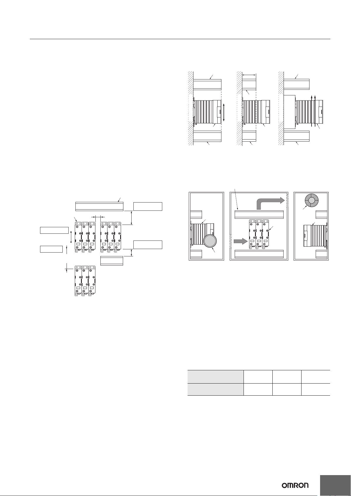
Mounting to Control Panel
If the panel is airtight, heat from the G3PJ will build up inside, which
may reduce the current carry ability of the G3PJ or adversely affect
other electrical devices. Be sure to install ventilation holes on the top
and bottom of the panel.
The G3PJ Mounting Pitch (Panel Mounting)
Duct or other object blocking airflow
Between duct and
G3PJ
60 mm min.
Between duct and
G3PJ
30 mm min.
The G3PJ
Mounting direction
Vertical Direction
Host and slave
80 mm min.
10 mm min.
Relationship between the G3PJ and Ducts or Other
Objects Blocking Airflow
Incorrect Example Countermeasure 1 Countermeasure 2
Duct or other object
blocking airflow
Vertical
Mounting surface
The G3PJ The G3PJ
If the depth direction of
the G3PJ is obstructed by
ducts, the heat radiation
will be adversely affected.
Direction
Duct Duct Duct
50 mm max.
(No more
than 1/2
the SSR
depth is
recommended.)
Duct
Mounting surface
Use ducts that have a
shallow depth, to provide
a sufficient ventilation
area.
Duct
Airflow
Base
Mounting surface
The G3PJ
If the ducts cannot be made
lower, place the G3PJ on a
metal base so that it is not
surrounded by the ducts.
Ventilation Outside the Control Panel
Duct or other object blocking airflow
Be aware of airflow
Ventilation
outlet
The G3PJ
Air inlet
The G3PJ
(Axial Fan)
The G3PJ
Note: 1. If the air inlet or air outlet has a filter, clean the filter regularly
to prevent it from clogging to ensure an efficient flow of air.
2. Do not locate any objects around the air inlet or air outlet,
otherwise the objects may obstruct the proper ventilation of
the control panel.
3. A heat exchanger, if used, should be located in front of the
G3PJ to ensure the efficiency of the heat exchanger.
G3PJ Ambient Temperature
The rated current of the G3PJ is measured at an ambient temperature
of 40°C.
The G3PJ uses a semiconductor to switch the load. This causes the
temperature inside the control panel to increase due to heating
resulting from the flow of electrical current through the load. The G3PJ
reliability can be increased by adding a ventilation fan to the control
panel to dispel this heat, thus lowering the ambient temperature of the
G3PJ.
(Arrhenius's law suggests that life expectancy is doubled by each
10°C reduction in ambient temperature.)
The G3PJ rated current
(A)
Required number of fans
per the G3PJ
Example: For 10 G3PJ with load currents of 15 A,
0.23 10 = 2.3
Thus, 3 fans would be required.
Note: 1. Size of fans: 92 mm 92 mm, Air volume: 0.7 m
Ambient temperature of control panel: 30C
2. If there are other instruments that generate heat in the
control panel in addition to the G3PJ, more ventilation will
be required.
3. Ambient temperature: The temperature that will allow the
G3PJ to cool by convection or other means.
15 A 25 A 35 A
0.23 0.39 0.54
3
/min,
9
Page 10

MEMO
10
Page 11

Terms and Conditions Agreement
Read and understand this catalog.
Please read and understand this catalog before purchasing the products. Please consult your OMRON representative if you have
any questions or comments.
Warranties.
(a) Exclusive Warranty. Omron’s exclusive warranty is that the Products will be free from defects in materials and workmanship
for a period of twelve months from the date of sale by Omron (or such other period expressed in writing
by Omron). Omron disclaims all other warranties, express or implied.
(b) Limitations. OMRON MAKES NO WARRANTY OR REPRESENTATION, EXPRESS OR IMPLIED, ABOUT
NON-INFRINGEMENT, MERCHANTABILITY OR FITNESS FOR A PARTICULAR PURPOSE OF THE
PRODUCTS. BUYER ACKNOWLEDGES THAT IT ALONE HAS DETERMINED THAT THE PRODUCTS WILL
SUITABLY MEET THE REQUIREMENTS OF THEIR INTENDED USE.
Omron further disclaims all warranties and responsibility of any type for claims or expenses based on infringement by the Products
or otherwise of any intellectual property right. (c) Buyer Remedy. Omron’s sole obligation hereunder shall be, at Omron’s election,
to (i) replace (in the form originally shipped with Buyer responsible for labor charges for removal or replacement thereof) the
non-complying Product, (ii) repair the non-complying Product, or (iii) repay or credit Buyer an amount equal to the purchase price
of the non-complying Product; provided that in no event shall Omron be responsible for warranty, repair, indemnity or any other
claims or expenses regarding the Products unless Omron’s analysis confirms that the Products were properly handled, stored,
installed and maintained and not subject to contamination, abuse, misuse or inappropriate modification. Return of any Products by
Buyer must be approved in writing by Omron before shipment. Omron Companies shall not be liable for the suitability or
unsuitability or the results from the use of Products in combination with any electrical or electronic components, circuits, system
assemblies or any other materials or substances or environments. Any advice, recommendations or information given orally or in
writing, are not to be construed as an amendment or addition to the above warranty.
See http://www.omron.com/global/ or contact your Omron representative for published information.
Limitation on Liability; Etc.
OMRON COMPANIES SHALL NOT BE LIABLE FOR SPECIAL, INDIRECT, INCIDENTAL, OR CONSEQUENTIAL DAMAGES,
LOSS OF PROFITS OR PRODUCTION OR COMMERCIAL LOSS IN ANY WAY CONNECTED WITH THE PRODUCTS,
WHETHER SUCH CLAIM IS BASED IN CONTRACT, WARRANTY, NEGLIGENCE OR STRICT LIABILITY.
Further, in no event shall liability of Omron Companies exceed the individual price of the Product on which liability is asserted.
Suitability of Use.
Omron Companies shall not be responsible for conformity with any standards, codes or regulations which apply to the
combination of the Product in the Buyer’s application or use of the Product. At Buyer’s request, Omron will provide applicable
third party certification documents identifying ratings and limitations of use which apply to the Product. This information by itself is
not sufficient for a complete determination of the suitability of the Product in combination with the end product, machine, system,
or other application or use. Buyer shall be solely responsible for determining appropriateness of the particular Product with
respect to Buyer’s application, product or system. Buyer shall take application responsibility in all cases.
NEVER USE THE PRODUCT FOR AN APPLICATION INVOLVING SERIOUS RISK TO LIFE OR PROPERTY OR IN LARGE
QUANTITIES WITHOUT ENSURING THAT THE SYSTEM AS A WHOLE HAS BEEN DESIGNED TO ADDRESS THE RISKS,
AND THAT THE OMRON PRODUCT(S) IS PROPERLY RATED AND INSTALLED FOR THE INTENDED USE WITHIN THE
OVERALL EQUIPMENT OR SYSTEM.
Programmable Products.
Omron Companies shall not be responsible for the user’s programming of a programmable Product, or any consequence thereof.
Performance Data.
Data presented in Omron Company websites, catalogs and other materials is provided as a guide for the user in determining
suitability and does not constitute a warranty. It may represent the result of Omron’s test conditions, and the user must correlate it
to actual application requirements. Actual performance is subject to the Omron’s Warranty and Limitations of Liability.
Change in Specifications.
Product specifications and accessories may be changed at any time based on improvements and other reasons. It is our practice
to change part numbers when published ratings or features are changed, or when significant construction changes are made.
However, some specifications of the Product may be changed without any notice. When in doubt, special part numbers may be
assigned to fix or establish key specifications for your application. Please consult with your Omron’s representative at any time to
confirm actual specifications of purchased Product.
Errors and Omissions.
Information presented by Omron Companies has been checked and is believed to be accurate; however, no responsibility is
assumed for clerical, typographical or proofreading errors or omissions.
Page 12

OMRON Corporation
Kyoto, JAPAN
Industrial Automation Company
Contact: www.ia.omron.com
Regional Headquarters
OMRON EUROPE B.V.
Wegalaan 67-69, 2132 JD Hoofddorp
The Netherlands
Tel: (31)2356-81-300/Fax: (31)2356-81-388
OMRON ASIA PACIFIC PTE. LTD.
No. 438A Alexandra Road # 05-05/08 (Lobby 2),
Alexandra Technopark,
Singapore 119967
Tel: (65) 6835-3011/Fax: (65) 6835-2711
OMRON ELECTRONICS LLC
2895 Greenspoint Parkway, Suite 200
Hoffman Estates, IL 60169 U.S.A.
Tel: (1) 847-843-7900/Fax: (1) 847-843-7787
OMRON (CHINA) CO., LTD.
Room 2211, Bank of China Towe r,
200 Yin Cheng Zhong Road,
PuDong New Area, Shanghai, 200120, China
Tel: (86) 21-5037-2222/Fax: (86) 21-5037-2200
Authorized Distributor:
© OMRON Corporation 2016 All Rights Reserved.
In the interest of product improvement,
specifications are subject to change without notice.
Cat. No. J210-E2-01A-X
0316
 Loading...