

Omron G3PE-245B DC12-24, G3PE-215B DC12-24, G3PE-215BL DC12-24, G3PE-225BL DC12-24, G3PE-235BL DC12-24 User Manual
...Page 1
CSM_G3PE-Single-phase_DS_E_2_1
1
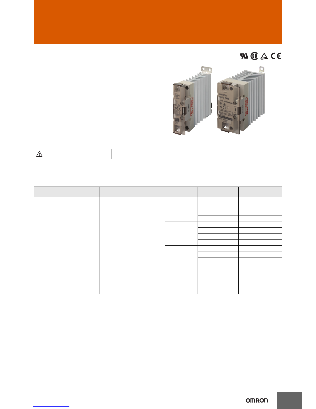
Solid State Relays for Heaters
G3PE-Single-phase
Compact, Slim-profile SSRs with Heat
Sinks. Models with No Zero Cross for
a Wide Range of Applications.
• RoHS compliant.
• Models also available with no zero cross
• Surge pass protection improved surge dielectric strength for
output currents. (OMRON testing)
• Compact with a slim profile.
• Mount to DIN Track or with screws.
• Conforms to UL, CSA, and EN standards (TÜV certification).
Ordering Information
List of Models
* The applicable load current depends on the ambient temperature. For details, refer to Load Current vs. Ambient Temperature in Engineering
Data on page 3.
Refer to Safety Precautions for All G3PE
Models.
Number of
phases
Insulation
method
Operation
indicator
Rated input
voltage
Zero cross
function
Applicable load * Model
Single-phase
Phototriac
coupler
Yes (yellow) 12 to 24 VDC
Yes
15 A, 100 to 240 VAC G3PE-215B DC12-24
25 A, 100 to 240 VAC G3PE-225B DC12-24
35 A, 100 to 240 VAC G3PE-235B DC12-24
45 A, 100 to 240 VAC G3PE-245B DC12-24
No
15 A, 100 to 240 VAC G3PE-215BL DC12-24
25 A, 100 to 240 VAC G3PE-225BL DC12-24
35 A, 100 to 240 VAC G3PE-235BL DC12-24
45 A, 100 to 240 VAC G3PE-245BL DC12-24
Yes
15 A, 200 to 480 VAC G3PE-515B DC12-24
25 A, 200 to 480 VAC G3PE-525B DC12-24
35 A, 200 to 480 VAC G3PE-535B DC12-24
45 A, 200 to 480 VAC G3PE-545B DC12-24
No
15 A, 200 to 480 VAC G3PE-515BL DC12-24
25 A, 200 to 480 VAC G3PE-525BL DC12-24
35 A, 200 to 480 VAC G3PE-535BL DC12-24
45 A, 200 to 480 VAC G3PE-545BL DC12-24
Page 2

G3PE-Single-phase
2
Specifications
Certification
UL508, CSA22.2 No.14, and EN60947-4-3
Ratings
Input (at an Ambient Temperature of 25°C)
Output
* The applicable load current depends on the ambient temperature. For details, refer to Load Current vs. Ambient Temperature in Engineering
Data on page 3.
Characteristics
Item
Model
Rated voltage
Operating voltage
range
Rated input current
Voltage level
Must operate voltage Must release voltage
G3PE-@@@B
12 to 24 VDC 9.6 to 30 VDC
7 mA max.
9.6 VDC max. 1.0 VDC max.
G3PE-@@@BL 15 mA max.
Model
G3PE-215B(L) G3PE-225B(L) G3PE-235B(L) G3PE-245B(L) G3PE-515B(L) G3PE-525B(L) G3PE-535B(L) G3PE-545B(L)
Item
Rated load voltage 100 to 240 VAC (50/60 Hz) 200 to 480 VAC (50/60 Hz)
Load voltage range 75 to 264 VAC (50/60 Hz) 180 to 528 VAC (50/60 Hz)
Applicable load current *0.1 to 15 A
(at 40°C)
0.1 to 25 A
(at 40°C)
0.5 to 35 A
(at 25°C)
0.5 to 45 A
(at 25°C)
0.1 to 15 A
(at 40°C)
0.1 to 25 A
(at 40°C)
0.5 to 35 A
(at 25°C)
0.5 to 45 A
(at 25°C)
Inrush current
resistance
150 A
(60 Hz,
1 cycle)
220 A
(60 Hz,
1cycle)
440 A
(60 Hz, 1 cycle)
150 A
(60 Hz,
1 cycle)
220 A
(60 Hz,
1 cycle)
440 A
(60 Hz, 1 cycle)
Permissible I2t
(reference value)
121A
2
s 260A2s 1,260A2s 128A2s1,350A
2
s 6,600A2s
Applicable load
(resistive load)
3 kW
(at 200 VAC)
5 kW
(at 200 VAC)
7 kW
(at 200 VAC)
9 kW
(at 200 VAC)
6 kW
(at 400 VAC)
10 kW
(at 400 VAC)
14 kW
(at 400 VAC)
18 kW
(at 400 VAC)
Model
G3PE
-215B
G3PE
-225B
G3PE
-235B
G3PE
-245B
G3PE
-215BL
G3PE
-225BL
G3PE
-235BL
G3PE
-245BL
Item
Operate time 1/2 of load power source cycle + 1 ms max. 1 ms max.
Release time 1/2 of load power source cycle + 1 ms max.
Output ON voltage drop 1.6 V (RMS) max.
Leakage current 10 mA max. (at 200 VAC)
Insulation resistance 100 MΩ min. (at 500 VDC)
Dielectric strength 2,500 VAC, 50/60 Hz for 1 min
Vibration resistance 10 to 55 to10 Hz, 0.375-mm single amplitude (0.75-mm double amplitude) (Mounted to DIN track)
Shock resistance Destruction: 294 m/s2 (Mounted to DIN track)
Ambient storage
temperature
−30 to 100°C (with no icing or condensation)
Ambient operating
temperature
−30 to 80°C (with no icing or condensation)
Ambient operating
humidity
45% to 85%
Weight Approx. 240 g Approx. 400 g Approx. 240 g Approx. 400 g
Model
G3PE
-515B
G3PE
-525B
G3PE
-535B
G3PE
-545B
G3PE
-515BL
G3PE
-525BL
G3PE
-535BL
G3PE
-545BL
Item
Operate time 1/2 of load power source cycle + 1 ms max. 1 ms max.
Release time 1/2 of load power source cycle + 1 ms max.
Output ON voltage drop 1.8 V (RMS) max.
Leakage current 20 mA max. (at 480 VAC)
Insulation resistance 100 MΩ min. (at 500 VDC)
Dielectric strength 2,500 VAC, 50/60 Hz for 1 min
Vibration resistance 10 to 55 to10 Hz, 0.375-mm single amplitude (0.75-mm double amplitude) (Mounted to DIN track)
Shock resistance Destruction: 294 m/s2 (Mounted to DIN track)
Ambient storage
temperature
−30 to 100°C (with no icing or condensation)
Ambient operating
temperature
−30 to 80°C (with no icing or condensation)
Ambient operating
humidity
45% to 85%
Weight Approx. 240 g Approx. 400 g Approx. 240 g Approx. 400 g
Page 3
3
G3PE-Single-phase
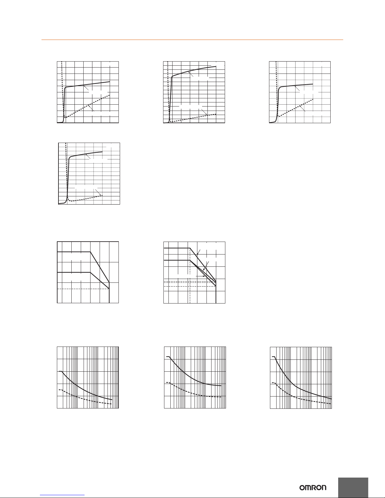
Engineering Data
Input Voltage vs. Input Impedance and Input Voltage vs. Input Current
G3PE-2@@B G3PE-2@@BL G3PE-5@@B
G3PE-5@@BL
Load Current vs. Ambient Temperature
G3PE-215B(L), G3PE-225B(L)
G3PE-515B(L), G3PE-525B(L)
G3PE-235B(L), G3PE-245B(L)
G3PE-535B(L), G3PE-545B(L)
Inrush Current Resistance: Non-repetitive
Keep the inrush current to below the inrush current resistance value (i.e., below the broken line) if it occurs repetitively.
G3PE-215B(L), G3PE-515B(L) G3PE-225B(L), G3PE-525B(L) G3PE-235B(L), G3PE-245B(L)
G3PE-535B(L), G3PE-545B(L)
10
9
8
7
6
5
4
3
2
1
0
0 5
10 15 20 25 30 35
Input voltage (V)
Input current
Input impedance
Input current (mA)
Input impedance (kΩ)
Ta = 25°C
15
14
13
12
11
10
9
8
7
6
5
4
3
2
1
0
0 5
10 15 20 25 30 35
Input voltage (V)
Input current
Input impedance
Input current (mA)
Input impedance (kΩ)
Ta = 25°C
10
9
8
7
6
5
4
3
2
1
0
0 5
10 15 20 25 30 35
Input voltage (V)
Input current
Input impedance
Input current (mA)
Input impedance (kΩ)
Ta = 25°C
15
14
13
12
11
10
9
8
7
6
5
4
3
2
1
0
0 5
10 15 20 25 30 35
Input voltage (V)
Input current
Input impedance
Input current (mA)
Input impedance (kΩ)
Ta = 25°C
30
25
20
15
10
7
0
Load current (A)
−30 −20
0 20 40 60 80 100
Ambient temperature (°C)
G3PE-225B(L)
G3PE-525B(L)
G3PE-215B(L)
G3PE-515B(L)
−30 −20
0 20 40 60 80 100
18
17
14
25
50
45
40
35
30
20
10
0
G3PE-245B(L)
G3PE-545B(L)
G3PE-235B(L)
G3PE-535B(L)
Load current (A)
Ambient temperature (°C)
250
200
150
100
50
0
Inrush current (A. Peak)
Energized time (ms)
10 30 50
100
300 500 1,000 3,000 5,000
250
200
150
100
50
0
10 30 50
100
300 500 1,000 3,000 5,000
Inrush current (A. Peak)
Energized time (ms)
500
400
300
200
100
0
10 30 50
100
300 500 1,000 3,000 5,000
Inrush current (A. Peak)
Energized time (ms)
Page 4
G3PE-Single-phase
4
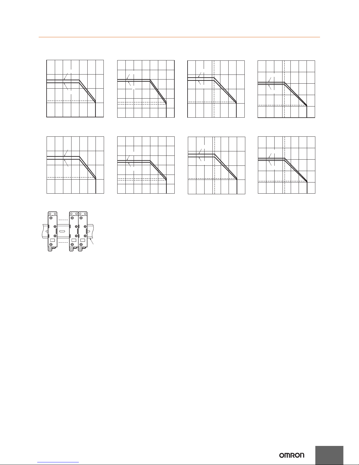
Close Mounting (3 or 8 SSRs)
G3PE-215B(L) G3PE-225B(L) G3PE-235B(L) G3PE-245B(L)
G3PE-515B(L) G3PE-525B(L) G3PE-535B(L) G3PE-545B(L)
Close Mounting Example
−40 −20 0 20 40 60 80 100
Ambient temperature (°C)
Load current (A)
5.7
20
15
13
12
10
5
0
3 Relays
8 Relays
−40 −20 0 20 40 60 80 100
8
30
25
20
19
15
5
10
7
0
Ambient temperature (°C)
Load current (A)
8 Relays
3 Relays
−40 −20 0 20 40 60 80 100
40
30
28
26
10
20
11
0
25
Ambient temperature (°C)
Load current (A)
8 Relays
3 Relays
50
40
31
30
29
10
20
11
0
−40 −20
0 20 40 60 80 100
25
Ambient temperature (°C)
Load current (A)
8 Relays
3 Relays
5.7
20
15
13
12
10
5
0
−40 −20
0 20 40 60 80 100
Ambient temperature (°C)
Load current (A)
3 Relays
8 Relays
7
30
25
20
16
17
15
5
10
6
0
Ambient temperature (°C)
Load current (A)
3 Relays
8 Relays
−40 −20
0 20 40 60 80 100
−40 −20 0 20 40 60 80 100
40
30
28
26
10
20
11
0
25
Ambient temperature (°C)
Load current (A)
3 Relays
8 Relays
50
40
31
30
29
10
20
11
0
−40 −20
0 20 40 60 80 100
25
Ambient temperature (°C)
Load current (A)
3 Relays
8 Relays
DIN Trac
k
Page 5
5
G3PE-Single-phase
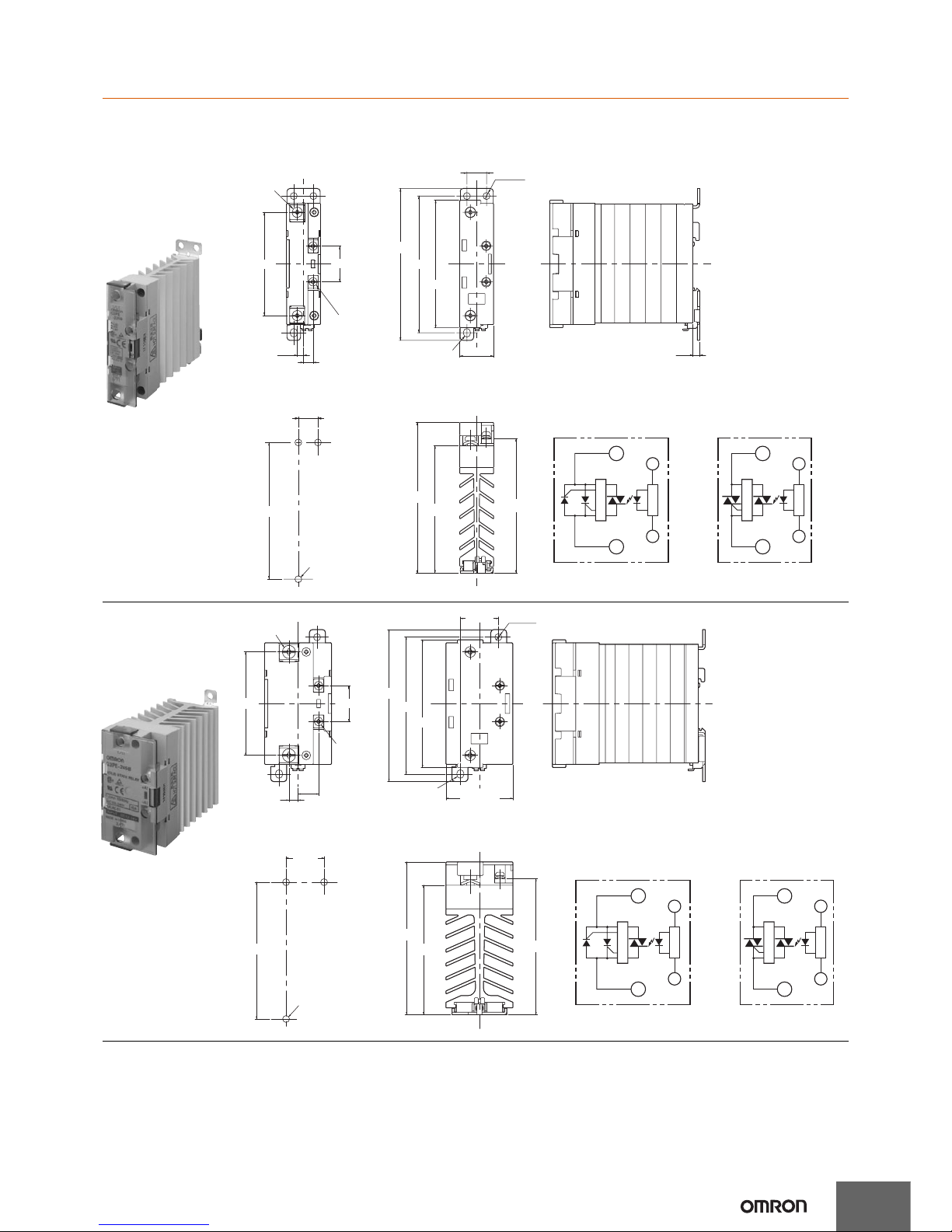
Dimensions
Note: All units are in millimeters unless otherwise indicated.
Solid State Relays
G3PE-215B(L)
G3PE-225B(L)
G3PE-515B(L)
G3PE-525B(L)
Two , M 4
68
4.2
6.3
Two ,
M3.5
Note: Without terminal cover.
24
13
±0.2
Two ,
4.6 dia.
100 max.
90
±0.2
84
22.5 max.
4.6 × 5.6
elliptical hole
Note: With terminal cover.
4.5
(90)
(85)
(100)
90
±0.3
Three, 4.5 dia.
or M4
Mounting Holes
13
±0.3
1
2
A1
A2
(+)
(−)
G3PE-5@@B
1
2
A1
A2
(+)
(−)
G3PE-2@@B
Terminal Arrangement/Internal Circuit Diagram
Output side
tiucric reggirT
Input side
Input side
Output side
tiucric reggirT
t
iu
cr
i
c t
u
pn
I
ti
u
cr
ic
t
u
pn
I
G3PE-235B(L)
G3PE-245B(L)
G3PE-535B(L)
G3PE-545B(L)
24
68
13.5
6
44.5 max.
84
Two , M 5
Two ,
M3.5
Note: Without terminal cover.
25
±0.2
4.6 dia.
100 max.
90
±0.2
4.6 × 5.6
elliptical hole
Note: With terminal cover.
(90)
(85)
(100)
90
±0.3
Three, 4.5 dia.
or M4
Mounting Holes
25
±0.3
1
2
A1
A2
(+)
(−)
G3PE-5@@B
1
2
A1
A2
(+)
(−)
G3PE-2@@B
Terminal Arrangement/Internal Circuit Diagram
Output side
tiucric reggirT
Input side
Input side
Output side
tiucric reggirT
t
iu
cr
i
c t
u
pn
I
ti
u
cr
ic
t
u
pn
I
Page 6

Read and Understand This Catalog
Please read and understand this catalog before purchasing the products. Please consult your OMRON representative if you have any questions or
comments.
Warranty and Limitations of Liability
WARRANTY
OMRON's exclusive warranty is that the products are free from defects in materials and workmanship for a period of one year (or other period if specified)
from date of sale by OMRON.
OMRON MAKES NO WARRANTY OR REPRESENTATION, EXPRESS OR IMPLIED, REGARDING NON-INFRINGEMENT, MERCHANTABILITY, OR
FITNESS FOR PARTICULAR PURPOSE OF THE PRODUCTS. ANY BUYER OR USER ACKNOWLEDGES THAT THE BUYER OR USER ALONE HAS
DETERMINED THAT THE PRODUCTS WILL SUITABLY MEET THE REQUIREMENTS OF THEIR INTENDED USE. OMRON DISCLAIMS ALL OTHER
WARRANTIES, EXPRESS OR IMPLIED.
LIMITATIONS OF LIABILITY
OMRON SHALL NOT BE RESPONSIBLE FOR SPECIAL, INDIRECT, OR CONSEQUENTIAL DAMAGES, LOSS OF PROFITS OR COMMERCIAL LOSS
IN ANY WAY CONNECTED WITH THE PRODUCTS, WHETHER SUCH CLAIM IS BASED ON CONTRACT, WARRANTY, NEGLIGENCE, OR STRICT
LIABILITY.
In no event shall the responsibility of OMRON for any act exceed the individual price of the product on which liability is asserted.
IN NO EVENT SHALL OMRON BE RESPONSIBLE FOR WARRANTY, REPAIR, OR OTHER CLAIMS REGARDING THE PRODUCTS UNLESS
OMRON'S ANALYSIS CONFIRMS THAT THE PRODUCTS WERE PROPERLY HANDLED, STORED, INSTALLED, AND MAINTAINED AND NOT
SUBJECT TO CONTAMINATION, ABUSE, MISUSE, OR INAPPROPRIATE MODIFICATION OR REPAIR.
Application Considerations
SUITABILITY FOR USE
OMRON shall not be responsible for conformity with any standards, codes, or regulations that apply to the combination of products in the customer's
application or use of the products.
At the customer's request, OMRON will provide applicable third party certification documents identifying ratings and limitations of use that apply to the
products. This information by itself is not sufficient for a complete determination of the suitability of the products in combination with the end product,
machine, system, or other application or use.
The following are some examples of applications for which particular attention must be given. This is not intended to be an exhaustive list of all possible
uses of the products, nor is it intended to imply that the uses listed may be suitable for the products:
•
Outdoor use, uses involving potential chemical contamination or electrical interference, or conditions or uses not described in this catalog.
•
Nuclear energy control systems, combustion systems, railroad systems, aviation systems, medical equipment, amusement machines, vehicles,
safety equipment, and installations subject to separate industry or government regulations.
•
Systems, machines, and equipment that could present a risk to life or property.
Please know and observe all prohibitions of use applicable to the products.
NEVER USE THE PRODUCTS FOR AN APPLICATION INVOLVING SERIOUS RISK TO LIFE OR PROPERTY WITHOUT ENSURING THAT THE
SYSTEM AS A WHOLE HAS BEEN DESIGNED TO ADDRESS THE RISKS, AND THAT THE OMRON PRODUCTS ARE PROPERLY RATED AND
INSTALLED FOR THE INTENDED USE WITHIN THE OVERALL EQUIPMENT OR SYSTEM.
PROGRAMMABLE PRODUCTS
OMRON shall not be responsible for the user's programming of a programmable product, or any consequence thereof.
Disclaimers
CHANGE IN SPECIFICATIONS
Product specifications and accessories may be changed at any time based on improvements and other reasons.
It is our practice to change model numbers when published ratings or features are changed, or when significant construction changes are made.
However, some specifications of the products may be changed without any notice. When in doubt, special model numbers may be assigned to fix or
establish key specifications for your application on your request. Please consult with your OMRON representative at any time to confirm actual
specifications of purchased products.
DIMENSIONS AND WEIGHTS
Dimensions and weights are nominal and are not to be used for manufacturing purposes, even when tolerances are shown.
PERFORMANCE DATA
Performance data given in this catalog is provided as a guide for the user in determining suitability and does not constitute a warranty. It may represent the
result of OMRON’s test conditions, and the users must correlate it to actual application requirements. Actual performance is subject to the OMRON
Warranty and Limitations of Liability.
ERRORS AND OMISSIONS
The information in this document has been carefully checked and is believed to be accurate; however, no responsibility is assumed for clerical,
typographical, or proofreading errors, or omissions.
2010.1
In the interest of product improvement, specifications are subject to change without notice.
OMRON Corporation
Industrial Automation Company
http://www.ia.omron.com/
(c)Copyright OMRON Corporation 2010 All Right Reserved.
Page 7

CSM_G3PE-Three-phase_DS_E_3_1
1
Solid State Contactors for Heaters
G3PE-Three-phase
Compact, Slim-profile SSRs with Heat Sinks.
Solid State Contactors for Three-phase
Heaters Reduced Installation Work
with DIN Track Mounting.
• RoHS compliant.
• Surge pass protection improved surge dielectric strength
for output currents. (OMRON testing)
• Slim design with 3-phase output and built-in heat sinks.
• DIN Track mounting types and screw mounting types are available.
All DIN Track mounting types mount to DIN Track
(applicable DIN Track: TR35-15Fe (IEC 60715)).
• Conforms to UL, CSA, and EN standards (TÜV certification).
Ordering Information
List of Models
Models with Built-in Heat Sinks
*1. The applicable load current depends on the ambient temperature. For details, refer to Load Current vs. Ambient Temperature in Engineering
Data on page 5.
*2.
The applicable DIN Track is the TR35-15Fe (IEC 60715). For details, refer to the mounting information in the Safety Precautions for All G3PE Models.
Refer to Safety Precautions for All G3PE
Models.
Number of
phases
Insulation
method
Operation
indicator
Rated input
voltage
Zero cross
function
Type Applicable load
*1
Number of
poles
Model
Three-phase
Phototriac
coupler
Yes (yellow) 12 to 24 VDC Yes
DIN track
mounting *2
15 A, 100 to 240 VAC
3 G3PE-215B-3N DC12-24
2 G3PE-215B-2N DC12-24
25 A, 100 to 240 VAC
3 G3PE-225B-3N DC12-24
2 G3PE-225B-2N DC12-24
35 A, 100 to 240 VAC
3 G3PE-235B-3N DC12-24
2 G3PE-235B-2N DC12-24
45 A, 100 to 240 VAC
3 G3PE-245B-3N DC12-24
2 G3PE-245B-2N DC12-24
15 A, 200 to 480 VAC
3 G3PE-515B-3N DC12-24
2 G3PE-515B-2N DC12-24
25 A, 200 to 480 VAC
3 G3PE-525B-3N DC12-24
2 G3PE-525B-2N DC12-24
35 A, 200 to 480 VAC
3 G3PE-535B-3N DC12-24
2 G3PE-535B-2N DC12-24
45 A, 200 to 480 VAC
3 G3PE-545B-3N DC12-24
2 G3PE-545B-2N DC12-24
Screw
mounting
15 A, 100 to 240 VAC
3 G3PE-215B-3 DC12-24
2 G3PE-215B-2 DC12-24
25 A, 100 to 240 VAC
3 G3PE-225B-3 DC12-24
2 G3PE-225B-2 DC12-24
35 A, 100 to 240 VAC
3 G3PE-235B-3 DC12-24
2 G3PE-235B-2 DC12-24
45 A, 100 to 240 VAC
3 G3PE-245B-3 DC12-24
2 G3PE-245B-2 DC12-24
15 A, 200 to 480 VAC
3 G3PE-515B-3 DC12-24
2 G3PE-515B-2 DC12-24
25 A, 200 to 480 VAC
3 G3PE-525B-3 DC12-24
2 G3PE-525B-2 DC12-24
35 A, 200 to 480 VAC
3 G3PE-535B-3 DC12-24
2 G3PE-535B-2 DC12-24
45 A, 200 to 480 VAC
3 G3PE-545B-3 DC12-24
2 G3PE-545B-2 DC12-24
Page 8

G3PE-Three-phase
2
Models with Externally Attached Heat Sinks
* The rated load current depends on the heat sink or radiator that is mounted. It also depends on the ambient temperature. For details, refer to
Load Current vs. Ambient Temperature.
Accessories (Order Separately)
Heat Sink
Number of
phases
Insulation
method
Operation
indicator
Rated input
voltage
Zero cross
function
Type Applicable load *
Number
of poles
Model
Three-phase
Phototriac
coupler
Yes (yellow) 12 to 24 VDC Yes
Externally
attached heat
sinks
15 A, 100 to 240 VAC
3 G3PE-215B-3H DC12-24
2 G3PE-215B-2H DC12-24
25 A, 100 to 240 VAC
3 G3PE-225B-3H DC12-24
2 G3PE-225B-2H DC12-24
35 A, 100 to 240 VAC
3 G3PE-235B-3H DC12-24
2 G3PE-235B-2H DC12-24
45 A, 100 to 240 VAC
3 G3PE-245B-3H DC12-24
2 G3PE-245B-2H DC12-24
15 A, 200 to 480 VAC
3 G3PE-515B-3H DC12-24
2 G3PE-515B-2H DC12-24
25 A, 200 to 480 VAC
3 G3PE-525B-3H DC12-24
2 G3PE-525B-2H DC12-24
35 A, 200 to 480 VAC
3 G3PE-535B-3H DC12-24
2 G3PE-535B-2H DC12-24
45 A, 200 to 480 VAC
3 G3PE-545B-3H DC12-24
2 G3PE-545B-2H DC12-24
Heat resistance Rth (s-a) (°C/W) Model
1.67 Y92B-P50
1.01 Y92B-P100
0.63 Y92B-P150
0.43 Y92B-P200
0.36 Y92B-P250
Page 9

3
G3PE-Three-phase
Specifications
Certification
UL508, CSA22.2 No.14, and EN60947-4-3
Ratings (at an Ambient Temperature of 25°C)
Operating Circuit (All Models)
Main Circuit of Models with Built-in Heat Sinks
*1. The applicable load current depends on the ambient temperature. For details, refer to Load Current vs. Ambient Temperature in Engineering
Data on page 5.
*2. Applicable Load
Use the following formula to calculate the maximum total capacity of a heater load for a three-phase balanced load with delta connections.
Maximum load capacity = Load current × Load voltage × √3
Example: 15 A × 200 V × √3 = 5,196 W ≅ 5.1 kW
Example: 15 A × 400 V × √3
= 10,392 W ≅ 10.3 kW
Main Circuit of Models with Externally Attached Heat Sinks
* The rated load current depends on the heat sink or radiator that is mounted. It also depends on the ambient temperature.
For details, refer to Load Current vs. Ambient Temperature in Engineering Data on page 5.
ItemModel Same for all models
Rated operating voltage 12 to 24 VDC
Operating voltage range 9.6 to 30 VDC
Rated input current (impedance) 10 mA max. (24 VDC)
Must-operate voltage 9.6 VDC max.
Must-release voltage 1 VDC min.
Insulation method Phototriac
Operation indicator Yellow LED
Model G3PE-
215B-
3(N)
G3PE215B-
2(N)
G3PE-
225B-
3(N)
G3PE-
225B-
2(N)
G3PE-
235B-
3(N)
G3PE-
235B-
2(N)
G3PE-
245B-
3(N)
G3PE-
245B-
2(N)
G3PE-
515B-
3(N)
G3PE515B-
2(N)
G3PE-
525B-
3(N)
G3PE-
525B-
2(N)
G3PE-
535B-
3(N)
G3PE-
535B-
2(N)
G3PE-
545B-
3(N)
G3PE545B-
2(N)
Item
Rated load voltage 100 to 240 VAC 200 to 480 VAC
Operating voltage
range
75 to 264 VAC 180 to 528 VAC
Rated load current *115 A (at 40°C) 25 A (at 40°C) 35 A (at 25°C) 45 A (at 25°C) 15 A (at 40°C) 25 A (at 40°C) 35 A (at 25°C) 45 A (at 25°C)
Minimum load current 0.2 A 0.5 A
Inrush current
resistance (peak
value)
150 A
(60 Hz, 1 cycle)
220 A
(60 Hz, 1 cycle)
440 A
(60 Hz, 1 cycle)
220 A
(60 Hz, 1 cycle)
440 A
(60 Hz, 1 cycle)
Permissible I2t
(reference value)
121A
2
s 260A2s 1,260A2s 260A2s 1,260A2s
Applicable load
(resistive load: AC1
class) *2
5.1 kW
(at 200 VAC)
8.6 kW
(at 200 VAC)
12.1 kW
(at 200 VAC)
15.5 kW
(at 200 VAC)
12.5 kW
(at 480 VAC)
20.7 kW
(at 480 VAC)
29.0 kW
(at 480 VAC)
37.4 kW
(at 480 VAC)
Model G3PE-
215B-
3H
G3PE215B-
2H
G3PE-
225B-
3HH
G3PE-
225B-
2H
G3PE-
235B-
3H
G3PE-
235B-
2H
G3PE-
245B-
3H
G3PE-
245B-
2H
G3PE-
515B-
3H
G3PE-
515B-
2H
G3PE-
525B-
3H
G3PE-
525B-
2H
G3PE-
535B-
3H
G3PE-
535B-
2H
G3PE-
545B-
3H
G3PE545B-
2H
Item
Rated load voltage 100 to 240 VAC 200 to 480 VAC
Operating voltage
range
75 to 264 VAC 180 to 528 VAC
Rated load current *15 A (at 40°C) 25 A (at 40°C) 35 A (at 25°C) 45 A (at 25°C) 15 A (at 40°C) 25 A (at 40°C) 35 A (at 25°C) 45 A (at 25°C)
Minimum load current 0.2 A 0.5 A
Inrush current
resistance (peak
value)
150 A
(60 Hz, 1 cycle)
220 A
(60 Hz, 1 cycle)
440 A
(60 Hz, 1 cycle)
220 A
(60 Hz, 1 cycle)
440 A
(60 Hz, 1 cycle)
Permissible I2t
(reference value)
121A
2
s 260A2s 1,260A2s 260A2s 1,260A2s
Applicable load
(resistive load: AC1
class)
Refer to Engineering Data on page 5.
Page 10

G3PE-Three-phase
4
Characteristics
Models with Built-in Heat Sinks
* The leakage current of phase S will be approximately √3 times larger if the 2-element model is used.
Models with Externally Attached Heat Sinks
* The leakage current of phase S will be approximately √3 times larger if the 2-element model is used.
Heat Sinks
Model G3PE-
215B-
3(N)
G3PE-
215B-
2(N)
G3PE-
225B-
3(N)
G3PE-
225B-
2(N)
G3PE-
235B-
3(N)
G3PE-
235B-
2(N)
G3PE-
245B-
3(N)
G3PE-
245B-
2(N)
G3PE-
515B-
3(N)
G3PE-
515B-
2(N)
G3PE-
525B-
3(N)
G3PE-
525B-
2(N)
G3PE-
535B-
3(N)
G3PE-
535B-
2(N)
G3PE-
545B-
3(N)
G3PE-
545B-
2(N)
Item
Operate time 1/2 of load power source cycle + 1 ms max.
Release time 1/2 of load power source cycle + 1 ms max.
Output ON
voltage drop
1.6 V (RMS) max. 1.8 V (RMS) max.
Leakage
current *
10 mA max. (at 200 VAC) 20 mA max. (at 480 VAC)
Insulation
resistance
100 MΩ min. (at 500 VDC)
Dielectric
strength
2,500 VAC, 50/60 Hz for 1 min
Vibration
resistance
• DIN Track mounting: 10 to 55 to 10 Hz, 0.175-mm single amplitude (0.35-mm double amplitude)
• Screw mounting: 10 to 55 to 10 Hz, 0.375-mm single amplitude (0.75-mm double amplitude)
Shock
resistance
294 m/s
2
(reverse mounting: 98 m/s2)
Ambient
storage
temperature
−30 to 100°C (with no icing or condensation)
Ambient
operating
temperature
−30 to 80°C (with no icing or condensation)
Ambient
operating
humidity
45% to 85%
Weight Approx. 1.25 kg
Approx.
1.45 kg
Approx.
1.25 kg
Approx.
1.65 kg
Approx.
1.45 kg
Approx.
2.0 kg
Approx.
1.65 kg
Approx. 1.25 kg
Approx.
1.45 kg
Approx.
1.25 kg
Approx.
1.65 kg
Approx.
1.45 kg
Approx.
2.0 kg
Approx.
1.65 kg
Model G3PE-
215B-
3H
G3PE-
215B-
2H
G3PE-
225B-
3H
G3PE-
225B-
2H
G3PE-
235B-
3H
G3PE-
235B-
2H
G3PE-
245B-
3H
G3PE-
245B-
2H
G3PE-
515B-
3H
G3PE-
515B-
2H
G3PE-
525B-
3H
G3PE-
525B-
2H
G3PE-
535B-
3H
G3PE-
535B-
2H
G3PE-
545B-
3H
G3PE-
545B-
2H
Item
Operate time 1/2 of load power source cycle + 1 ms max.
Release time 1/2 of load power source cycle + 1 ms max.
Output ON
voltage drop
1.6 V (RMS) max. 1.8 V (RMS) max.
Leakage
current
*
10 mA max. (at 200 VAC) 20 mA max. (at 480 VAC)
Insulation
resistance
100 MΩ min. (at 500 VDC)
Dielectric
strength
2,500 VAC, 50/60 Hz for 1 min
Vibration
resistance
10 to 55 to 10 Hz, 0.375-mm single amplitude (0.75-mm double amplitude)
Shock
resistance
Destruction: 294 m/s
2
Ambient
storage
temperature
−30 to 100°C (with no icing or condensation)
Ambient
operating
temperature
−30 to 80°C (with no icing or condensation)
Ambient
operating
humidity
45% to 85%
Weight Approx. 300 g
Model Weight
Y92B-P50 Approx. 450 g
Y92B-P100 Approx. 450 g
Y92B-P150 Approx. 600 g
Y92B-P200 Approx. 850 g
Y92B-P250 Approx. 1,200 g
Page 11

5
G3PE-Three-phase
Engineering Data
Input Voltage vs. Input Impedance and Input Voltage vs. Input Current
G3PE-2@@B-@@ G3PE-5@@B-@@
5 10 15 20 25 30 35
10
9
8
7
6
5
4
3
2
1
0
Input voltage (V)
Input current
Input impedance
Input current (mA)
Input impedance (kΩ)
15
14
13
12
11
10
9
8
7
6
5
4
3
2
1
0
0 5
10 15 20 25 30 35
Ta = 25°C
Input voltage (V)
Input current
Input impedance
Input current (mA)
Input impedance (kΩ)
Load Current vs. Ambient Temperature
Models with Built-in Heat Sinks
G3PE-215B-3(N), G3PE-225B-3(N)
G3PE-215B-2(N), G3PE-225B-2(N)
G3PE-515B-3(N), G3PE-525B-3(N)
G3PE-515B-2(N), G3PE-525B-2(N)
G3PE-235B-3(N), G3PE-245B-3(N)
G3PE-235B-2(N), G3PE-245B-2(N)
G3PE-535B-3(N), G3PE-545B-3(N)
G3PE-535B-2(N), G3PE-545B-2(N)
30
25
20
15
10
7
0
−30 −20 0 20 40 60 80 100
G3PE-225B-3(N)
G3PE-225B-2(N)
G3PE-525B-3(N)
G3PE-525B-2(N)
G3PE-215B-3(N)
G3PE-215B-2(N)
G3PE-515B-3(N)
G3PE-515B-2(N)
Load current (A)
Ambient temperature (°C)
50
45
40
35
30
20
14
10
0
−30 −20 0 20 40 60 80 100
18
12
G3PE-245B-3(N)
G3PE-245B-2(N)
G3PE-545B-3(N)
G3PE-545B-2(N)
G3PE-235B-3(N)
G3PE-235B-2(N)
G3PE-535B-3(N)
G3PE-535B-2(N)
25
*
Load current (A)
Ambient temperature (°C)
* The dotted lines in the charts are
the UL derating curves for the
G3PE-235B-3(N), G3PE-245B-3(N),
G3PE-235B-2(N), G3PE-245B-2(N),
G3PE-535B-3(N), G3PE-545B-3(N),
G3PE-535B-2(N), G3PE-545B-2(N).
Models with Externally Attached Heat Sinks
G3PE-215B-3H(-2H)
G3PE-225B-3H(-2H)
G3PE-515B-3H(-2H)
G3PE-525B-3H(-2H)
G3PE-235B-3H(-2H)
G3PE-245B-3H(-2H)
G3PE-535B-3H(-2H)
G3PE-545B-3H(-2H)
−30 −20 0 20 40 60 80 100
G3PE-225B-3H(-2H)
G3PE-525B-3H(-2H)
G3PE-215B-3H(-2H)
G3PE-515B-3H(-2H)
10
8
6
4
2
0
5
Load current (A)
Ambient temperature (°C)
−30 −20 0 20 40 60 80 100
G3PE-235B-3H(-2H)
G3PE-245B-3H(-2H)
G3PE-535B-3H(-2H)
G3PE-545B-3H(-2H)
10
8
6
4
2
0
25
Load current (A)
Ambient temperature (°C)
Page 12

G3PE-Three-phase
6
Models with Externally Attached Heat Sinks
Heat Resistance Rth (Junction/SSR Back
Surface)
Heat Resistance of Heat Sinks
Note: If a commercially available heat sink is used, use one that has
a heat resistance equal to or lower than a standard OMRON
Heat Sink.
Inrush Current Resistance: Non-repetitive
Keep the inrush current to below the inrush current resistance value (i.e., below the broken line) if it occurs repetitively.
G3PE-215B-3(N)(H)
G3PE-215B-2(N)(H)
G3PE-225B-3(N)(H), G3PE-525B-3(N)(H)
G3PE-225B-2(N)(H), G3PE-525B-2(N)(H)
G3PE-515B-3(N)(H),
G3PE-515B-2(N)(H),
G3PE-235B-3(N)(H), G3PE-535B-3(N)(H)
G3PE-235B-2(N)(H), G3PE-535B-2(N)(H)
G3PE-245B-3(N)(H), G3PE-545B-3(N)(H)
G3PE-245B-2(N)(H), G3PE-545B-2(N)(H)
250
200
150
100
50
0
10 30 50
100 300 500 1,000 3,000 5,000
Inrush current (A. Peak)
Energized time (ms)
250
200
150
100
50
0
10 30 50
100 300 500 1,000 3,000 5,000
Inrush current (A. Peak)
Energized time (ms)
500
400
300
200
100
0
10 30 50
100 300 500 1,000 3,000 5,000
Inrush current (A. Peak)
Energized time (ms)
Heat Sink Area vs. Load Current (40°C and 80°C)
G3PE-225B-3H G3PE-525B-3H
Note: The heat sink area is the combined
area of all surfaces of the heat sink
that radiate heat.
For the G3PE-525B-3H, when a
current of 18 A flows through the SSR
at 40°C, the graph shows that a heat
sink area of about 2,500 cm
2
would
be required. Therefore, if the heat
sink is square, one side of an
aluminum plate in the heat sink must
be 36 cm or longer (√2,500
(cm2)/2 =
36 cm (rounded to a whole number)).
Load current (A)
0 10 20 30 40
Heat s ink area (cm
2
)
30,000
50,000
10,000
5,000
3,000
1,000
500
300
100
Ambient temperature
+ 80°C
Ambient temperature
+ 40°C
Aluminum plate t = 3.0
0 10 20 30 40
30,000
50,000
10,000
5,000
3,000
1,000
500
300
100
Load current (A)
Heat s ink area (cm
2
)
Ambient temperature
+ 80°C
Ambient temperature
+ 40°C
Aluminum plate t = 3.0
Model Rth (°C/W)
G3PE-215B-3H 1.05
G3PE-225B-3H 0.57
G3PE-235B-3H 0.57
G3PE-245B-3H 0.57
Model Rth (°C/W)
Y92B-P50 1.67
Y92B-P100 1.01
Y92B-P150 0.63
Y92B-P200 0.43
Y92B-P250 0.36
Page 13

7
G3PE-Three-phase
Dimensions
Note: All units are in millimeters unless otherwise indicated.
Solid State Relays
68
68
32.2
20
Six, M4
0.5
20
Two, 4.6-dia. mounting holes
Four, 8 dia.
Two, M3.5
100
max.
84.5
max.
90
64
80 max.
19.1
64
±0.3
90
±0.3
Four, 4.5 dia. or M4
23.2
120 max.
35
max.
24
Two, R2.3
mounting
holes
A1
A2
Input circuit
Input circuit
Input circuit
Input circuit
A1
A2
Terminal Arrangement/Internal Circuit Diagram
G3PE-2@5B-2N
G3PE-215B-3N
L1/R
T1/U T2/V T3/W
L2/S L3/T
L1/R
T1/U T2/V T3/W
L2/S L3/T
L1/R
T1/U T2/V T3/W
L2/S L3/T
A1
A2
(+)
(−)
(+)
(−)
(+)
(−)
(+)
(−)
G3PE-5@5B-2N
L1/R
T1/U T2/V T3/W
L2/S L3/T
A1
A2
G3PE-515E-3N
Note: Without terminal cover. Note: With terminal cover.
Mounting Holes
Models with
DIN Track Mounting
G3PE-215B-3N
G3PE-215B-2N
G3PE-225B-2N
G3PE-515B-3N
G3PE-515B-2N
G3PE-525B-2N
120
max.
84.5
max.
110100
64
80 max.
68
68
32.2
20
Six, M5 (35-A type)
Six, M4 (25-A type)
0.5
20
24
19.1
64
±0.3
110
±0.3
23.2
120 max.
35
max.
Two, 4.6-dia. mounting holes
Four, 8 dia.
Two, M3.5
Four, 4.5 dia. or M4
Two, R2.3
mounting
holes
A1
A2
A1
A2
Terminal Arrangement/Internal Circuit Diagram
G3PE-235B-2N
G3PE-225B-3N
L1/R
T1/U T2/V T3/W
L2/S L3/T
L1/R
T1/U T2/V T3/W
L2/S L3/T
L1/R
T1/U T2/V T3/W
L2/S L3/T
A1
A2
G3PE-535B-2N
L1/R
T1/U T2/V T3/W
L2/S L3/T
A1
A2
G3PE-525B-3N
Input circuit
(+)
(−)
Input circuit
(+)
(−)
Input circuit
(+)
(−)
Input circuit
(+)
(−)
Models with
DIN Track Mounting
G3PE-225B-3N
G3PE-235B-2N
G3PE-525B-3N
G3PE-535B-2N
Note: Without terminal cover. Note: With terminal cover.
Mounting Holes
Page 14

G3PE-Three-phase
8
A1
A2
A1
A2
Terminal Arrangement/Internal Circuit Diagram
G3PE-245B-2N
G3PE-235B-3N
L1/R
T1/U T2/V T3/W
L2/S L3/T
L1/R
T1/U T2/V T3/W
L2/S L3/T
L1/R
T1/U T2/V T3/W
L2/S L3/T
A1
A2
G3PE-545B-2N
L1/R
T1/U T2/V T3/W
L2/S L3/T
A1
A2
G3PE-535B-3N
Input circuit
(+)
(−)
Input circuit
(+)
(−)
Input circuit
(+)
(−)
Input circuit
(+)
(−)
140
max.
84.5
max.
130120
64
80 max.
68
68
32.2
20
0.5
20
24
19.1
64
±0.3
130
±0.3
23.2
120 max.
35
max.
Six, M5
Two, 4.6-dia. mounting holes
Four, 8 dia.
Two, M3.5
Four, 4.5 dia. or M4
Two, R2.3
mounting
holes
Models with
DIN Track Mounting
G3PE-235B-3N
G3PE-245B-2N
G3PE-535B-3N
G3PE-545B-2N
Note: Without terminal cover. Note: With terminal cover.
Mounting Holes
140
max.
84.5
max.
130120
64
80 max.
110 max.
68
68
32.2
20
0.5
20
24
19.1
64
±0.3
130
±0.3
23.2
120 max.
35
max.
Six, M5
Two, 4.6-dia. mounting holes
Four, 8 dia.
Two, M3.5
Four, 4.5 dia. or M4
Two, R2.3
mounting
holes
A1
A2
Terminal Arrangement/Internal Circuit Diagram
G3PE245B-3N
L1/R
T1/U T2/V T3/W
L2/S L3/T
L1/R
T1/U T2/V T3/W
L2/S L3/T
A1
A2
G3PE-545B-3N
Input circuit
(+)
(−)
Input circuit
(+)
(−)
Models with
DIN Track Mounting
G3PE-245B-3N
G3PE-545B-3N
Note: Without terminal cover. Note: With terminal cover.
Mounting Holes
Page 15

9
G3PE-Three-phase
24
68
0.5
20 20
68
32.2
Two, M3.5
Six, M4
90
50
80 max.
84.5
max.
100
max.
4.6 dia.
4.6 × 5.6
elliptical hole
50
±0.3
90
±0.3
Two, 4.5 dia. or M4
Mounting Holes
55 max.
35
max.
23.2
19.1
L1/R
T1/U T2/V T3/W
L2/S L3/T
A1
A2
G3PE-215B-2
L1/R
T1/U T2/V T3/W
L2/S L3/T
A1
A2
G3PE-515B-2
Terminal Arrangement/Internal Circuit Diagram
Input circuit
(+)
(−)
Input circuit
(+)
(−)
DIN Track or screw mounting
Models with Screw Mounting
G3PE-215B-2
G3PE-515B-2
Note: Without terminal cover.
Note: With terminal cover.
A1
A2
A1
A2
G3PE-225B-2
G3PE-215B-3
L1/R
T1/U T2/V T3/W
L2/S L3/T
L1/R
T1/U T2/V T3/W
L2/S L3/T
L1/R
T1/U T2/V T3/W
L2/S L3/T
A1
A2
G3PE-525B-2
L1/R
T1/U T2/V T3/W
L2/S L3/T
A1
A2
G3PE-515B-3
Terminal Arrangement/Internal Circuit Diagram
Input circuit
(+)
(−)
Input circuit
(+)
(−)
Input circuit
(+)
(−)
Input circuit
(+)
(−)
60
80 max.
100
110.5 max.
90
80.5
84.5
max.
5
24
0.5
20 20
32.2
60
±0.3
100
±0.3
Four, 4.5 dia. or M4
70 max.
35
max.
Four, R2.5
Two, M3.5
Six, M4
Mounting Holes
23.2
19.1
68
68
For screw mounting only
Models with Screw Mounting
G3PE-215B-3
G3PE-225B-2
G3PE-515B-3
G3PE-525B-2
Note: Without terminal cover. Note: With terminal cover.
Page 16

G3PE-Three-phase
10
84.5
max.
90
80 max.
90
100
110.5 max.
110.5
max.
5
24
0.5
20 20
32.2
90
±0.3
100
±0.3
Four, 4.5 dia. or M4
70 max.
35
max.
Four, R2.5
Two, M3.5
Six, M5
(G3PE-@35B-2)
Six, M4
(G3PE-@25B-3)
Mounting Holes
23.2
19.1
68
68
For screw mounting only
A1
A2
A1
A2
G3PE-235B-2
G3PE-225B-3
L1/R
T1/U T2/V T3/W
L2/S L3/T
L1/R
T1/U T2/V T3/W
L2/S L3/T
L1/R
T1/U T2/V T3/W
L2/S L3/T
A1
A2
G3PE-535B-2
L1/R
T1/U T2/V T3/W
L2/S L3/T
A1
A2
G3PE-525B-3
Terminal Arrangement/Internal Circuit Diagram
Input circuit
(+)
(−)
Input circuit
(+)
(−)
Input circuit
(+)
(−)
Input circuit
(+)
(−)
Models with
Screw Mounting
G3PE-225B-3
G3PE-235B-2
G3PE-525B-3
G3PE-535B-2
Note: Without terminal cover. Note: With terminal cover.
A1
A2
A1
A2
G3PE-245B-2
G3PE-235B-3
L1/R
T1/U T2/V T3/W
L2/S L3/T
L1/R
T1/U T2/V T3/W
L2/S L3/T
L1/R
T1/U T2/V T3/W
L2/S L3/T
A1
A2
G3PE-545B-2
L1/R
T1/U T2/V T3/W
L2/S L3/T
A1
A2
G3PE-535B-3
Terminal Arrangement/Internal Circuit Diagram
Input circuit
(+)
(−)
Input circuit
(+)
(−)
Input circuit
(+)
(−)
Input circuit
(+)
(−)
84.5
max.
90
80 max.
110
120
130.5 max.
130.5
max.
5
24
0.5
20 20
32.2
90
±0.3
120
±0.3
Four, 4.5 dia. or M4
70 max.
35
max.
Four, R2.5
Two, M3.5
Six, M5
Mounting Holes
23.2
19.1
68
68
For screw mounting only
Models with
Screw Mounting
G3PE-235B-3
G3PE-245B-2
G3PE-535B-3
G3PE-545B-2
Note: Without terminal cover. Note: With terminal cover.
Page 17

11
G3PE-Three-phase
84.5
max.
150
80 max.
110
120
130.5 max.
190.5
max.
5
24
0.5
20 20
32.2
150
±0.3
120
±0.3
Four, 4.5 dia. or M4
70 max.
35
max.
Four, R2.5
Two, M3.5
Six, M5
Mounting Holes
23.2
19.1
68
68
A1
A2
G3PE-245B-3
L1/R
T1/U T2/V T3/W
L2/S L3/T
L1/R
T1/U T2/V T3/W
L2/S L3/T
A1
A2
G3PE-545B-3
Terminal Arrangement/Internal Circuit Diagram
Input circuit
(+)
(−)
Input circuit
(+)
(−)
For screw mounting only
Models with Screw Mounting
G3PE-245B-3
G3PE-545B-3
Note: Without terminal cover. Note: With terminal cover.
35
max.
23.2
19.1
80
84.5
max.
80 max.
24
0.5
20 20
32.2
68
Four, 8 dia.
Four, 4.5 dia.
Two, M3.5
Four, 4.5 dia. or M4
68
±0.3
68
±0.3
Mounting Holes
Six, M4
(G3PE-@15B-@H/-@25B-@H)
Six, M5
(G3PE-@35B-@H/-@45B-@H)
9
8 dia.
4.5 dia.
68
Models with Externally Attached Heat Sinks
G3PE-215B-3H
G3PE-215B-2H
G3PE-225B-3H
G3PE-225B-2H
G3PE-235B-3H
G3PE-235B-2H
G3PE-245B-3H
G3PE-245B-2H
G3PE-515B-3H
G3PE-515B-2H
G3PE-525B-3H
G3PE-525B-2H
G3PE-535B-3H
G3PE-535B-2H
G3PE-545B-3H
G3PE-545B-2H
Note: Without terminal cover.
Note: With terminal cover.
A1
A2
A1
A2
G3PE-2@5B-2H
G3PE-2@5B-3H
L1/R
T1/U T2/V T3/W
L2/S L3/T
L1/R
T1/U T2/V T3/W
L2/S L3/T
L1/R
T1/U T2/V T3/W
L2/S L3/T
A1
A2
G3PE-5@5B-2H
L1/R
T1/U T2/V T3/W
L2/S L3/T
A1
A2
G3PE-5@5B-3H
Terminal Arrangement/Internal Circuit Diagram
Input circuit
(+)
(−)
Input circuit
(+)
(−)
Input circuit
(+)
(−)
Input circuit
(+)
(−)
Page 18

G3PE-Three-phase
12
Accessories (Order Separately)
Heat Sink
Y92B-P50 (Mounts to DIN Track.)
For G3PE-215B-2H and
G3PE-515B-2H
Heat Sink
Y92B-P100
For G3PE-215B-3H,
G3PE-225B-2H,
G3PE-515B-3H, and
G3PE-525B-2H
Heat Sink
Y92B-P150
For G3PE-225B-3H,
G3PE-235B-2H,
G3PE-525B-3H, and
G3PE-535B-2H
Heat Sink
Y92B-P200
For G3PE-235B-3H,
G3PE-245B-2H,
G3PE-535B-3H, and
G3PE-545B-2H
Heat Sink
Y92B-P250
For G3PE-245B-3H and
G3PE-545B-3H
68 90
68
50
80 max.
80.5
max.
55 max.
100
max.
4.6 dia.
4.6 × 5.6
elliptical
hole
50
±0.3
90
±0.3
Two, 4.5 dia. or M4
Mounting Holes
68
110.5 max.
60
68
Four, M4
100
80.5
max.
70 max.
Four,
R2.5
60
±0.3
100
±0.3
Four, 4.5 dia. or M4
Mounting Holes
5
90
±0.3
100
±0.3
Four, 4.5 dia. or M4
Mounting Holes
68
90
68
100
110.5 max.
110.5
max.
70 max.
Four, M4
5
Four,
R2.5
Mounting Holes
68
120
70 max.
68
120
130.5 max.
Four, M4
90
±0.3
120
±0.3
90
130.5
max.
5
Four, 4.5 dia. or M4
Four,
R2.5
5
68
68
47.6
Four, M4M4-D10
M4-D10
120
120
130.5 max.
190.5
max.
70 max.
150
150
±0.3
120
±0.3
Four, 4.5 dia. or M4
Mounting Holes
Four,
R2.5
Page 19

Read and Understand This Catalog
Please read and understand this catalog before purchasing the products. Please consult your OMRON representative if you have any questions or
comments.
Warranty and Limitations of Liability
WARRANTY
OMRON's exclusive warranty is that the products are free from defects in materials and workmanship for a period of one year (or other period if specified)
from date of sale by OMRON.
OMRON MAKES NO WARRANTY OR REPRESENTATION, EXPRESS OR IMPLIED, REGARDING NON-INFRINGEMENT, MERCHANTABILITY, OR
FITNESS FOR PARTICULAR PURPOSE OF THE PRODUCTS. ANY BUYER OR USER ACKNOWLEDGES THAT THE BUYER OR USER ALONE HAS
DETERMINED THAT THE PRODUCTS WILL SUITABLY MEET THE REQUIREMENTS OF THEIR INTENDED USE. OMRON DISCLAIMS ALL OTHER
WARRANTIES, EXPRESS OR IMPLIED.
LIMITATIONS OF LIABILITY
OMRON SHALL NOT BE RESPONSIBLE FOR SPECIAL, INDIRECT, OR CONSEQUENTIAL DAMAGES, LOSS OF PROFITS OR COMMERCIAL LOSS
IN ANY WAY CONNECTED WITH THE PRODUCTS, WHETHER SUCH CLAIM IS BASED ON CONTRACT, WARRANTY, NEGLIGENCE, OR STRICT
LIABILITY.
In no event shall the responsibility of OMRON for any act exceed the individual price of the product on which liability is asserted.
IN NO EVENT SHALL OMRON BE RESPONSIBLE FOR WARRANTY, REPAIR, OR OTHER CLAIMS REGARDING THE PRODUCTS UNLESS
OMRON'S ANALYSIS CONFIRMS THAT THE PRODUCTS WERE PROPERLY HANDLED, STORED, INSTALLED, AND MAINTAINED AND NOT
SUBJECT TO CONTAMINATION, ABUSE, MISUSE, OR INAPPROPRIATE MODIFICATION OR REPAIR.
Application Considerations
SUITABILITY FOR USE
OMRON shall not be responsible for conformity with any standards, codes, or regulations that apply to the combination of products in the customer's
application or use of the products.
At the customer's request, OMRON will provide applicable third party certification documents identifying ratings and limitations of use that apply to the
products. This information by itself is not sufficient for a complete determination of the suitability of the products in combination with the end product,
machine, system, or other application or use.
The following are some examples of applications for which particular attention must be given. This is not intended to be an exhaustive list of all possible
uses of the products, nor is it intended to imply that the uses listed may be suitable for the products:
•
Outdoor use, uses involving potential chemical contamination or electrical interference, or conditions or uses not described in this catalog.
•
Nuclear energy control systems, combustion systems, railroad systems, aviation systems, medical equipment, amusement machines, vehicles,
safety equipment, and installations subject to separate industry or government regulations.
•
Systems, machines, and equipment that could present a risk to life or property.
Please know and observe all prohibitions of use applicable to the products.
NEVER USE THE PRODUCTS FOR AN APPLICATION INVOLVING SERIOUS RISK TO LIFE OR PROPERTY WITHOUT ENSURING THAT THE
SYSTEM AS A WHOLE HAS BEEN DESIGNED TO ADDRESS THE RISKS, AND THAT THE OMRON PRODUCTS ARE PROPERLY RATED AND
INSTALLED FOR THE INTENDED USE WITHIN THE OVERALL EQUIPMENT OR SYSTEM.
PROGRAMMABLE PRODUCTS
OMRON shall not be responsible for the user's programming of a programmable product, or any consequence thereof.
Disclaimers
CHANGE IN SPECIFICATIONS
Product specifications and accessories may be changed at any time based on improvements and other reasons.
It is our practice to change model numbers when published ratings or features are changed, or when significant construction changes are made.
However, some specifications of the products may be changed without any notice. When in doubt, special model numbers may be assigned to fix or
establish key specifications for your application on your request. Please consult with your OMRON representative at any time to confirm actual
specifications of purchased products.
DIMENSIONS AND WEIGHTS
Dimensions and weights are nominal and are not to be used for manufacturing purposes, even when tolerances are shown.
PERFORMANCE DATA
Performance data given in this catalog is provided as a guide for the user in determining suitability and does not constitute a warranty. It may represent the
result of OMRON’s test conditions, and the users must correlate it to actual application requirements. Actual performance is subject to the OMRON
Warranty and Limitations of Liability.
ERRORS AND OMISSIONS
The information in this document has been carefully checked and is believed to be accurate; however, no responsibility is assumed for clerical,
typographical, or proofreading errors, or omissions.
2010.1
In the interest of product improvement, specifications are subject to change without notice.
OMRON Corporation
Industrial Automation Company
http://www.ia.omron.com/
(c)Copyright OMRON Corporation 2010 All Right Reserved.
 Loading...