

Omron G3PE-245B DC12-24, G3PE-225B DC12-24, G3PE-215B DC12-24, G3PE-235B DC12-24, G3PE-225BL DC12-24 Series Manual
...Page 1
Solid-state Relays
G3PE
Slim-profile, Single-phase Industrial SSRs with
Built-in Heatsink for Heater Applications
• Excellent short term surge absorption testing
at 30kV+ (reference only).
• Slim 22.5mm width for 15A and 25A models.
• Models available with zero cross and random fire.
• Yellow LED indicator.
• Mount to DIN-rail or direct to panel with screws.
• All models RoHS compliant.
Refer to Safety Precautions on page 5.
Ordering Information
List of Models
Isolation method Operation indicator Rated input voltage Zero cross function Applicable load * Model
15 A, 100 to 240 VAC G3PE-215B DC12-24
Yes
Phototriac coupler Yes (yellow) 12 to 24 VDC
No
* The applicable load current depends on the ambient temperature. For details, refer to Load Current vs. Ambient Temperature in Engineering
Data on page 3.
25 A, 100 to 240 VAC G3PE-225B DC12-24
35 A, 100 to 240 VAC G3PE-235B DC12-24
45 A, 100 to 240 VAC G3PE-245B DC12-24
15 A, 100 to 240 VAC G3PE-215BL DC12-24
25 A, 100 to 240 VAC G3PE-225BL DC12-24
35 A, 100 to 240 VAC G3PE-235BL DC12-24
45 A, 100 to 240 VAC G3PE-245BL DC12-24
1
Page 2
G3PE
Specifications
Certification
UL 508, CSA 22.2 No. 14, EN 60947-4-3
Ratings
Input (at an Ambient Temperature of 25°C)
Model
Item
Rated voltage 12 to 24 VDC
Operating voltage range 9.6 to 30 VDC
Rated input current 7 mA max. 15 mA max.
Must
operate
Voltage
level
voltage
Must
release
voltage
Output
Model
Item
Rated load voltage 100 to 240 VAC (50/60 Hz)
Load voltage range 75 to 264 VAC (50/60 Hz)
Applicable load current *
Inrush current non-repetitive
Permissible I2t (reference
value)
Applicable load (resistive
load)
* The applicable load current depends on the ambient temperature. For details, refer to Load Current vs. Ambient Temperature in Engineering
Data on page 3.
G3PE-215B(L) G3PE-225B(L) G3PE-235B(L) G3PE-245B(L)
0.1 to 15 A
(at 40°C)
150 A
(60 Hz, 1 cycle)
121A
3 kW
(at 200 VAC)
G3PE-@@@B G3PE-@@@BL
9.6 VDC max.
1.0 VDC min.
0.1 to 25 A
(at 40°C)
220 A
(60 Hz, 1 cycle)
2
s 260A2s 1,260A2s
5 kW
(at 200 VAC)
0.5 to 35 A
(at 25°C)
440 A
(60 Hz, 1 cycle)
7 kW
(at 200 VAC)
0.5 to 45 A
(at 25°C)
9 kW
(at 200 VAC)
Characteristics
Model
Item
Operate time 1/2 of load power source cycle + 1 ms max. 1 ms max.
Release time 1/2 of load power source cycle + 1 ms max.
Output ON voltage 1.6 V (RMS) max.
Leakage current 10 mA max. (at 200 VAC)
Insulation resistance 100 MΩ min. (at 500 VDC)
Dielectric strength 2,500 VAC, 50/60 Hz for 1 min
Vibration resistance 10 to 55 Hz; 0.75-mm double amplitude when mounted to DIN-rail
Shock resistance Destruction: 294 m/s
Ambient storage
temperature
Ambient operating
temperature
Ambient operating humidity 45% to 85%
Weight Approx. 240 g Approx. 400 g Approx. 240 g Approx. 400 g
G3PE
-215B
−30 to 100°C (with no icing or condensation)
−30 to 80°C (with no icing or condensation)
G3PE
-225B
2
mounted to DIN-rail
G3PE
-235B
G3PE
-245B
G3PE
-215BL
G3PE
-225BL
G3PE
-235BL
G3PE
-245BL
2
Page 3
Engineering Data
k
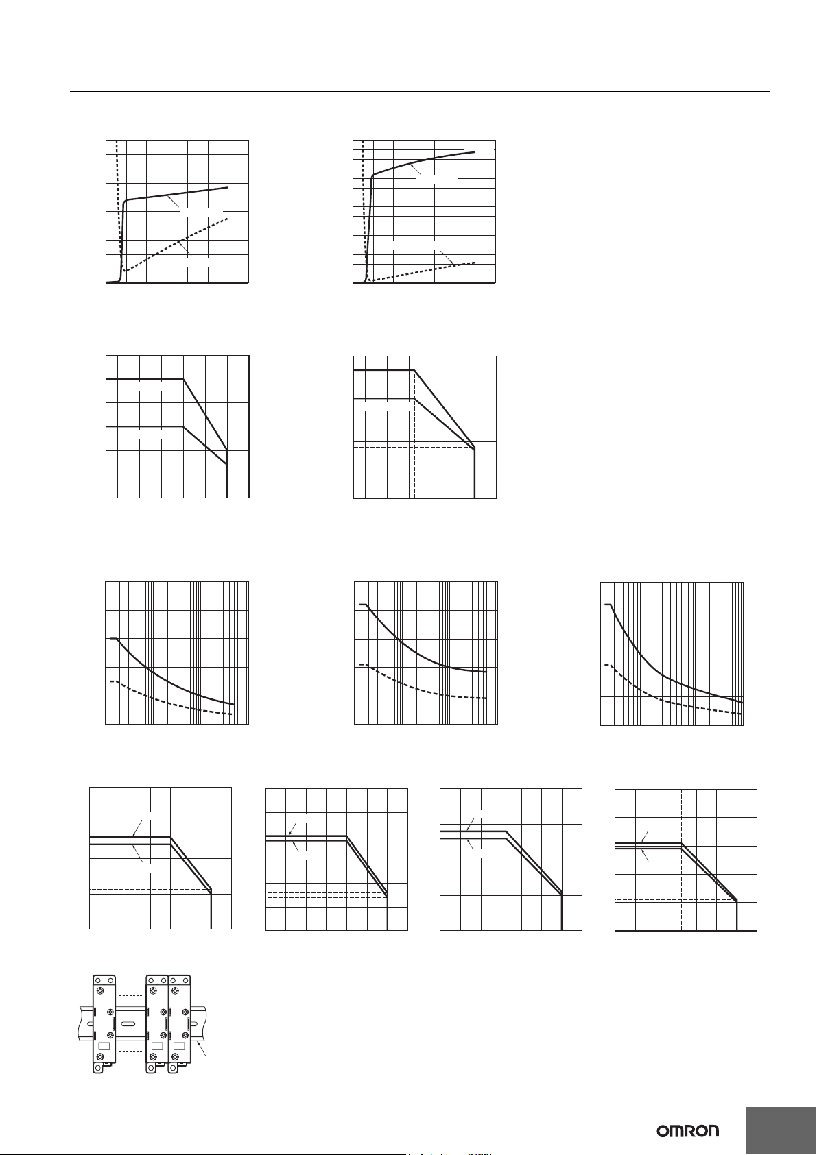
Input Voltage vs. Input Impedance and Input Voltage vs. Input Current
G3PE-2@@B G3PE-2@@BL
10
9
8
7
Input current (mA)
6
Input impedance (kΩ)
5
4
3
2
1
0
0 5
10 15 20 25 30 35
Ta = 25°C
Input current
Input impedance
Input voltage (V)
Load Current vs. Ambient Temperature
G3PE-215B(L), G3PE-225B(L) G3PE-235B(L), G3PE-245B(L)
30
25
G3PE-225B(L)
Load current (A)
20
15
G3PE-215B(L)
10
7
15
14
13
12
11
10
Input current (mA)
9
Input impedance (kΩ)
8
7
6
5
4
3
2
1
0
50
45
40
35
Load current (A)
30
20
18
17
10
Input current
Input impedance
0 5
10 15 20 25 30 35
G3PE-245B(L)
G3PE-235B(L)
Ta = 25°C
Input voltage (V)
G3PE
0
−30 −20
0 20 40 60 80 100
Ambient temperature (°C)
0
−30 −20
0 20 40 60 80 100
25
Ambient temperature (°C)
One Cycle Surge Current: Non-repetitive
Inrush current must stay below the inrush current resistance value (i.e., below the dashed line) if it occurs repetitively.
G3PE-215B(L) G3PE-225B(L) G3PE-235B(L), G3PE-245B(L)
250
200
150
Inrush current (A. Peak)
100
50
0
10 30 50
100
300 500 1,000 3,000 5,000
Energized time (ms)
250
200
150
Inrush current (A. Peak)
100
50
0
10 30 50
100
300 500 1,000 3,000 5,000
Energized time (ms)
500
400
300
Inrush current (A. Peak)
200
100
0
10 30 50
100
300 500 1,000 3,000 5,000
Energized time (ms)
Close Mounting (3 or 8 SSRs)
G3PE-215B(L) G3PE-225B(L) G3PE-235B(L) G3PE-245B(L)
20
15
13
Load current (A)
12
10
5.7
5
0
−40 −20 0 20 40 60 80 100
3 Relays
8 Relays
Ambient temperature (°C)
30
25
3 Relays
20
Load current (A)
19
8 Relays
15
10
8
7
5
0
−40 −20 0 20 40 60 80 100
Ambient temperature (°C)
40
3 Relays
30
28
26
Load current (A)
8 Relays
20
11
10
0
−40 −20 0 20 40 60 80 100
25
Ambient temperature (°C)
50
40
3 Relays
31
Load current (A)
30
29
8 Relays
20
11
10
0
−40 −20
0 20 40 60 80 100
25
Ambient temperature (°C)
Close Mounting Example
DIN Trac
3
Page 4

G3PE
Dimensions
Note: All units are in millimeters unless otherwise indicated.
Solid State Relays
G3PE-215B(L)
G3PE-225B(L)
Two , M 4
68
24
Two, M3.5
100 max.
Two ,
±0.2
13
4.6 dia.
±0.2
90
84
G3PE-235B(L)
G3PE-245B(L)
4.2
6.3
Note: Without terminal cover.
Mounting Holes
±0.3
13
±0.3
90
Three, 4.5 dia. or M4
Two, M5
68
24
Two, M3.5
Elliptical hole:
4.6 × 5.6
Note: With terminal cover.
(100)
100 max.
±0.2
90
22.5 max.
(85)
84
(90)
±0.2
4.6 dia.
25
4.5
4
13.5
6
Note: Without terminal cover.
Mounting Holes
±0.3
25
±0.3
90
Three, 4.5 dia. or M4
Elliptical hole:
4.6 × 5.6
Note: With terminal cover.
(100)
(85)
44.5 max.
(90)
Page 5

Safety Precautions
Refer to Safety Precautions for All Solid State Relays.
!CAUTION
Minor electrical shock may occasionally occur.
Do not touch the G3PE terminal section (i.e., currentcarrying parts) while the power is being supplied.
Cover must remain on relay at all times.
The G3PE may rupture if short-circuit current flows.
As protection against accidents due to shortcircuiting, be sure to install protective devices, such
as fuses and no-fuse breakers, on the power supply
side.
Minor electrical shock may occasionally occur.
Do not touch the main circuit terminals on the SSR
immediately after the power supply has been turned
OFF.
Shock may result due to the electrical charge stored in the builtin snubber circuit.
Minor burns may occasionally occur.
Do not touch the SSR or the heat sink while the power
is being supplied or immediately after the power
supply has been turned OFF. The SSR and heat sink
may become extremely hot.
Precautions for Safe Use
OMRON constantly strives to improve quality and reliability.
SSRs, however, use semiconductors, and semiconductors may
commonly malfunction or fail. In particular, it may not be possible to
ensure safety if the SSRs are used outside the rated ranges.
Therefore, always use the SSRs within the ratings. When using an
SSR, always design the system to ensure safety and prevent human
accidents, fires, and social harm in the event of SSR failure. System
design must include measures such as system redundancy,
measures to prevent fires from spreading, and designs to prevent
malfunction.
Transport
Do not transport the G3PE under the following conditions.
Doing so may result in damage, malfunction, or deterioration of
performance characteristics.
• Conditions in which the G3PE may be subject to water.
• Conditions in which the G3PE may be subject to high temperature
or high humidity.
• Conditions in which the G3PE is not packaged.
Operating and Storage Environments
Do not use or store the G3PE in the following locations. Doing so may
result in damage, malfunction, or deterioration of performance
characteristics.
• Locations subject to rainwater or water splashes.
• Locations subject to exposure to water, oil, or chemicals.
• Locations subject to high temperature or high humidity.
• Do not store in locations subject to ambient storage temperatures
outside the range −30 to 100°C.
• Do not use in locations subject to relative humidity outside the
range 45% to 85%.
• Locations subject to corrosive gases.
• Locations subject to dust (especially iron dust) or salts.
• Locations subject to direct sunlight.
• Locations subject to shock or vibration.
G3PE
Installation and Handling
• Do not block the movement of the air surrounding the G3PE or heat
sink. Abnormal heating of G3PE may result in shorting
of output elements or burn damage.
• Do not use the G3PE if the heat radiation fins have been bent by
being dropped. Doing so may result in malfunction due to a
reduction in the heat radiation performance.
• Do not handle the G3PE with oily or dusty (especially iron dust)
hands. Doing so may result in malfunction.
• Make sure the heat sink that comes with the G3PE Relay stays
attached to it.
Installation and Mounting
• Mount the G3PE in the specified direction. Otherwise excessive
heat generated by the G3PE may cause short-circuit failures of the
output elements or burn damage.
• Make sure that there is no excess ambient temperature rise due to
the heat generation of the G3PE. If the G3PE is mounted inside a
panel, install a fan so that the interior of the panel is fully ventilated.
• Make sure the DIN track is securely mounted. Otherwise, the
G3PE may fall.
• When mounting the heat sink, do not allow any foreign matter
between the heat sink and the mounting surface. Foreign matter
may cause malfunction due to a reduction in the heat radiation
performance.
Installation and Wiring
• Use wires that are suited to the load current.
Otherwise, excessive heat generated by the wires may cause
burning.
• Do not use wires with a damaged outer covering.
Otherwise, it may result in electric shock or ground leakage.
• Do not wire any wiring in the same duct or conduit as power or
high-tension lines. Otherwise, inductive noise may damage the
G3PE or cause it to malfunction.
• When tightening terminal screws, prevent any non-conducting
material from becoming caught between the screws and the
tightening surface.
Otherwise, excessive heat generated by the terminal may cause
burning.
• Do not use the G3PE with loose terminal screws.
Otherwise, excessive heat generated by the wire may cause
burning.
• For the G3PE models with a carry current of 35 A or larger, use M5
crimp terminals that are an appropriate size for the diameter of the
wire.
• Always turn OFF the power supply before performing wiring. Not
doing so may cause electrical shock.
Installation and Usage
• Select a load within the rated values. Not doing so may result in
malfunction, failure, or burning.
• Select a power supply within the rated frequencies. Not doing so
may result in malfunction, failure, or burning.
• The G3PE provides a circuit to prevent photocoupler damage by
forcibly arcing the output element for surge voltages applied to the
load. The G3PE therefore cannot be used for motor loads. Doing
so may result in load motor malfunction.
5
Page 6

G3PE
Precautions for Correct Use
The SSR in operation may cause an unexpected accident.
Therefore it is necessary to test the SSR under the variety of
conditions that are possible. As for the characteristics of the SSR, it is
necessary to consider differences in characteristics between
individual SSRs.
The ratings in this catalog are tested values in a temperature range
between 15°C and 30°C, a relative humidity range between 25% and
85%, and an atmospheric pressure range between 86 and 106 kPa.
It will be necessary to provide the above conditions as well as the load
conditions if the user wants to confirm the ratings of specific SSRs.
Causes of Failure
• Do not drop the G3PE or subject it to abnormal vibration or shock
during transportation or mounting. Doing so may result in
deterioration of performance, malfunction, or failure.
• Tighten each terminal to the torque specified below. Improper
tightening may result in abnormal heat generation at the terminal,
which may cause burning.
Terminals Screw terminal diameter Tightening torque
Input terminals M3.5 0.59 to 1.18 N·m
Output
terminals
• Do not supply overvoltage to the input circuits or output circuits.
Doing so may result in failure or burning.
• Do not use or store the G3PE in the following conditions. Doing so
may result in deterioration of performance.
• Locations subject to static electricity or noise
• Locations subject to strong electric or magnetic fields
• Locations subject to radioactivity
Mounting
The G3PE is heavy. Firmly mount the DIN track and secure both ends
with End Plates for DIN-track-mounting models. When mounting the
G3PE directly to a panel, firmly secure it to the panel.
Mounted on a
vertical surface
Vertical
Direction
Note: Make sure that the load current is 50% of the rated load current
when the G3PE is mounted horizontally.
For details on close mounting, refer to the related information
under performance characteristics.
Mount the G3PE in a direction so that the markings read
naturally.
When close-mounting G3PE SSRs, check Load Current vs.
Ambient Temperature under Engineering Data on page 3.
M4 0.98 to 1.47 N·m
M5 1.57 to 2.45 N·m
Mounted on a
horizontal surface
Panel
Panel
Wiring
• When using crimp terminals, refer to the terminal clearances
shown below.
Output Terminal Section
15-A and 25-A Models 35-A and 45-A Models
10 mm 13 mm
Output Terminal Section
12.4 mm
7.0 mm
M3.5
12.9 mm
M5 (35 A, 45 A)M4 (15 A, 25 A)
10 mm
• Make sure that all lead wires are thick enough for the current.
Fuses
• Use a quick-burning fuse on the output terminals to prevent
accidents due to short-circuiting. Use a fuse with equal or greater
performance than those given in the following table.
Recommended Fuse Capacity
Rated G3PE output
current
15 A G3PE@15B Series
25 A G3PE@25B Series
35 A G3PE@35B Series
45 A G3PE@45B Series
Applicable SSR
Fuse
(IEC 60269-4)
32 A
63 A
EMC Connection
Make EMC connections according to the following figure.
• Connect a capacitor to the load power supply.
• The input cable must be no longer than 3 m.
Load
Input Output
3 m max.
G3PE
Recommended Capacitor (Film Capacitor)
G3PE-2@@B Series: 1 µF, 250 VAC
G3PE-5@@B Series: 0.5 µF, 500 VAC
EMI
This is a Class A product (for industrial environments). In a domestic
environment, the G3PE may cause radio interference, in which case
the user may be required to take appropriate measures.
6
Page 7

G3PE
Noise and Surge Effects
If noise or an electrical surge occurs that exceeds the malfunction
withstand limit for the G3PE output circuit, the output will turn ON for
a maximum of one half cycle to absorb the noise or surge. Confirm
that turning the output ON for a half cycle will not cause a problem for
the device or system in which the G3PE is being used prior to actual
use. The G3PE malfunction withstand limit is shown below.
• Malfunction withstand limit (reference value): 500 V
Note: This value was measured under the following conditions.
Noise duration: 100 ns and 1 µs
Repetition period: 100 Hz
Noise application time: 3 min
Mounting to Control Panel
The G3PE is heavy. Firmly mount the DIN track and secure both ends
with End Plates for DIN-track-mounting models. When mounting the
G3PE directly to a panel, firmly secure it to the panel.
If the panel is airtight, heat from the SSR will build up inside, which
may reduce the current carry ability of the SSR or adversely affect
other electrical devices.
SSR Mounting Pitch (Panel Mounting)
Duct or other object blocking airflow
Between duct and
G3PE
60 mm min.
Between duct and
G3PE
30 mm min.
Mounting direction
Vertical Direction
Host and slave
80 mm min.
SSR
10 mm min.
Relationship between the G3PE and ducts or
other objects blocking airflow
Incorrect Example Countermeasure 1 Countermeasure 2
Duct or other object
blocking airflow
50 mm max.
Duct
(No more
than 1/2
the G3PE
depth is
recommended.)
Duct
Airflow
Ventilation Outside the Control Panel
Duct or other object blocking airflow
Be aware of airflow
Ventilation
outlet
SSR
SSR
Air inlet
(Axial Fan)
SSR
Note: 1. If the air inlet or air outlet has a filter, clean the filter regularly
to prevent it from clogging to ensure an efficient flow of air.
2. Do not locate any objects around the air inlet or air outlet,
otherwise the objects may obstruct the proper ventilation of
the control panel.
3. A heat exchanger, if used, should be located in front of the
G3PE to ensure the efficiency of the heat exchanger.
G3PE Ambient Temperature
The rated current of the G3PE is measured at an ambient
temperature of 40°C.
The G3PE uses a semiconductor to switch the load. This causes the
temperature inside the control panel to increase due to heating
resulting from the flow of electrical current through the load. G3PE
reliability can be increased by adding a ventilation fan to the control
panel to dispel this heat, thus lowering the ambient temperature of the
G3PE.
(Arrhenius's law suggests that life expectancy is doubled by each
10°C reduction in ambient temperature.)
SSR rated current (A) 15 A 25 A 35 A 45 A
Required number of
fans per SSR
Example: For 10 G3PE SSRs with load currents of 15 A,
0.23 × 10 = 2.3
Thus, 3 fans would be required.
Note: 1. Size of fans: 92 mm × 92 mm, Air volume: 0.7 m
Ambient temperature of control panel: 30°C
2. If there are other instruments that generate heat in the
control panel in addition to SSRs, more ventilation will be
required.
3. Ambient temperature: The temperature that will allow the
SSR to cool by convection or other means.
0.23 0.39 0.54 0.70
3
/min,
Mounting surface
SSR SSR
If the depth direction of
the G3PE is obstructed by
ducts, the heat radiation
will be adversely affected.
Duct Duct Duct
Vertical
Direction
Mounting surface
Use ducts that have a
shallow depth, to provide
a sufficient ventilation
area.
Base
Mounting surface
If the ducts cannot be made
lower, place the G3PE on a
metal base so that it is not
surrounded by the ducts.
SSR
7
Page 8

Warranty and Application Considerations
Read and Understand this Catalog
Please read and understand this catalog before purchasing the products. Please consult your OMRON representative if you
have any questions or comments.
Warranty and Limitations of Liability
WARRANTY
OMRON's exclusive warranty is that the products are free from defects in materials and workmanship for a period of one year (or
other period if specified) from date of sale by OMRON.
OMRON MAKES NO WARRANTY OR REPRESENTATION, EXPRESS OR IMPLIED, REGARDING NON-INFRINGEMENT,
MERCHANTABILITY, OR FITNESS FOR PARTICULAR PURPOSE OF THE PRODUCTS. ANY BUYER OR USER
ACKNOWLEDGES THAT THE BUYER OR USER ALONE HAS DETERMINED THAT THE PRODUCTS WILL SUITABLY MEET
THE REQUIREMENTS OF THEIR INTENDED USE. OMRON DISCLAIMS ALL OTHER WARRANTIES, EXPRESS OR
IMPLIED.
LIMITATIONS OF LIABILITY
OMRON SHALL NOT BE RESPONSIBLE FOR SPECIAL, INDIRECT, OR CONSEQUENTIAL DAMAGES, LOSS OF PROFITS,
OR COMMERCIAL LOSS IN ANY WAY CONNECTED WITH THE PRODUCTS, WHETHER SUCH CLAIM IS BASED ON
CONTRACT, WARRANTY, NEGLIGENCE, OR STRICT LIABILITY.
In no event shall the responsibility of OMRON for any act exceed the individual price of the product on which liability is asserted.
IN NO EVENT SHALL OMRON BE RESPONSIBLE FOR WARRANTY, REPAIR, OR OTHER CLAIMS REGARDING THE
PRODUCTS UNLESS OMRON'S ANALYSIS CONFIRMS THAT THE PRODUCTS WERE PROPERLY HANDLED, STORED,
INSTALLED, AND MAINTAINED AND NOT SUBJECT TO CONTAMINATION, ABUSE, MISUSE, OR INAPPROPRIATE
MODIFICATION OR REPAIR.
Application Considerations
SUITABILITY FOR USE
OMRON shall not be responsible for conformity with any standards, codes, or regulations that apply to the combination of
products in the customer's application or use of the products.
Take all necessary steps to determine the suitability of the product for the systems, machines, and equipment with which it will
be used.
Know and observe all prohibitions of use applicable to this product.
NEVER USE THE PRODUCTS FOR AN APPLICATION INVOLVING SERIOUS RISK TO LIFE OR PROPERTY WITHOUT
ENSURING THAT THE SYSTEM AS A WHOLE HAS BEEN DESIGNED TO ADDRESS THE RISKS, AND THAT THE OMRON
PRODUCTS ARE PROPERLY RATED AND INSTALLED FOR THE INTENDED USE WITHIN THE OVERALL EQUIPMENT OR
SYSTEM.
Disclaimers
PERFORMANCE DATA
Performance data given in this catalog is provided as a guide for the user in determining suitability and does not constitute a
warranty. It may represent the result of OMRON's test conditions, and the users must correlate it to actual application
requirements. Actual performance is subject to the OMRON Warranty and Limitations of Liability.
CHANGE IN SPECIFICATIONS
Product specifications and accessories may be changed at any time based on improvements and other reasons. Consult with
your OMRON representative at any time to confirm actual specifications of purchased product.
DIMENSIONS AND WEIGHTS
Dimensions and weights are nominal and are not to be used for manufacturing purposes, even when tolerances are shown.
8
Page 9

Note: Specifications are subject to change. © 2008 Omron Electronics LLC Printed in U.S.A.
OMRON ELECTRONICS LLC • THE AMERICAS HEADQUARTERS
Schaumburg, IL USA • 847.843.7900 • 800.556.6766 • www.omron247.com
OMRON CANADA, INC. • HEAD OFFICE
Toronto, ON, Canada • 416.286.6465 • 866.986.6766 • www.omron.ca
OMRON ELETRÔNICA DO BRASIL LTDA • HEAD OFFICE
São Paulo, SP, Brasil • 55.11.2101.6300 • www.omron.com.br
OMRON ELECTRONICS MEXICO SA DE CV • HEAD OFFICE
Apodaca, N.L. • 52.811.156.99.10 • mela@omron.com
OMRON ARGENTINA • SALES OFFICE
Cono Sur • 54.11.4787.1129
OMRON CHILE • SALES OFFICE
Santiago 56.2206.4592
OTHER OMRON LATIN AMERICA SALES
56.2206.4592
J174-E1-01
 Loading...