

Page 1
Single-phase Solid State Relays for Heaters
Refer to Safety Precautions
G3PE
Slim Profile Industrial SSR with Heatsink
ideal for heater applications.
• Snubber circuit provides excellent short-term surge
absorption.
• 15A and 25A models have slim 22.5mm width.
• Zero cross or “fast turn on” models.
• DIN track or panel mounting possible.
• LED indicator standard on all single phase models.
• UL, CSA and TÜV approved
• RoHS compliant.
Ordering Information
■ List of Models
.
Number of
phases
Single-phase
* The applicable load current depends on the ambient temperature. For details, refer to Load Current vs. Ambient Temperature in the Engineering
Data section.
Isolation
method
Phototriac
coupler
Operation
indicator
Yes (yellow) 12 to 24 VDC
Rated input
voltage
Zero cross
function
Yes
No
Applicable load * Model
15 A, 100 to 240 VAC G3PE-215B DC12-24
25 A, 100 to 240 VAC G3PE-225B DC12-24
35 A, 100 to 240 VAC G3PE-235B DC12-24
45 A, 100 to 240 VAC G3PE-245B DC12-24
15 A, 100 to 240 VAC G3PE-215BL DC12-24
25 A, 100 to 240 VAC G3PE-225BL DC12-24
35 A, 100 to 240 VAC G3PE-235BL DC12-24
45 A, 100 to 240 VAC G3PE-245BL DC12-24
Single-phase Solid State Relays for Heaters G3PE 445
Page 2
Specifications
■ Ratings
Input (at an Ambient Temperature of 25°C)
Model
G3PE-@@@B 12 to 24 VDC 9.6 to 30 VDC 7 mA max. 9.6 VDC max. 1.0 VDC max.
G3PE-@@@BL 15 mA max.
Item
Rated voltage Operating voltage range Rated input current
Must operate voltage Must release voltage
Output
Model
Item
Rated load voltage 100 to 240 VAC (50/60 Hz)
Load voltage range 75 to 264 VAC (50/60 Hz)
Applicable load current * 0.1 to 15 A
Inrush current 150 A
2
Permissible I
(reference value)
Applicable load
(resistive load)
t
G3PE-215B(L) G3PE-225B(L) G3PE-235B(L) G3PE-245B(L)
(at 40°C)
(60 Hz, 1 cycle)
2
121A
s 260A2s 1,260A2s
3 kW
(at 200 VAC)
0.1 to 25 A
(at 40°C)
220 A
(60 Hz, 1 cycle)
5 kW
(at 200 VAC)
0.5 to 35 A
(at 25°C)
(60 Hz, 1 cycle)
7 kW
(at 200 VAC)
440 A
(at 200 VAC)
0.5 to 45 A
(at 25°C)
9 kW
* The applicable load current depends on the ambient temperature. For details, refer to Load Current vs. Ambient Temperature
■ Characteristics
Voltage level
Model
Item
Operate time 1/2 of load power source cycle + 1 ms max. 1 ms max.
Release time 1/2 of load power source cycle + 1 ms max.
Output ON voltage drop 1.6 V (RMS) max.
Leakage current 10 mA max. (at 200 VAC)
Insulation resistance 100 MΩ min. (at 500 VDC)
Dielectric strength 2,500 VAC, 50/60 Hz for 1 min
Vibration resistance 10 to 55 to10 Hz, 0.375-mm single amplitude (0.75-mm double amplitude) (Mounted to DIN track)
Shock resistance
Ambient storage temperature −30 to 100°C (with no icing or condensation)
Ambient operating
temperature
Ambient operating humidity 45% to 85%
Weight Approx. 240 g Approx. 400 g Approx. 240 g Approx. 400 g
G3PE-215B G3PE-225B G3PE-235B G3PE-245B G3PE-215BL G3PE-225BL G3PE-235BL G3PE-245BL
Destruction: 294 m/s
−30 to 80°C (with no icing or condensation)
2
(Mounted to DIN track)
446 Single-phase Solid State Relays for Heaters G3PE
Page 3
Engineering Data
10
9
8
7
6
5
4
3
2
1
0
0 5
10 15 20 25 30 35
Input voltage (V)
Input current
Input impedance
Input current (mA)
Input impedance (kΩ)
Ta = 25°C
15
14
13
12
11
10
9
8
7
6
5
4
3
2
1
0
0 5
10 15 20 25 30 35
Input voltage (V)
Input current
Input impedance
Input current (mA)
Input impedance (kΩ)
Ta = 25°C
−30 −20
0 20 40 60 80 100
18
17
14
25
50
45
40
35
30
20
10
0
G3PE-245B(L)
G3PE-235B(L)
Load current (A)
Ambient temperature (°C)
250
200
150
100
50
0
Inrush current (A. Peak)
Energized time (ms)
10 30 50
100
300 500 1,000 3,000 5,000
500
400
300
200
100
0
10 30 50
100
300 500 1,000 3,000 5,000
Inrush current (A. Peak)
Energized time (ms)
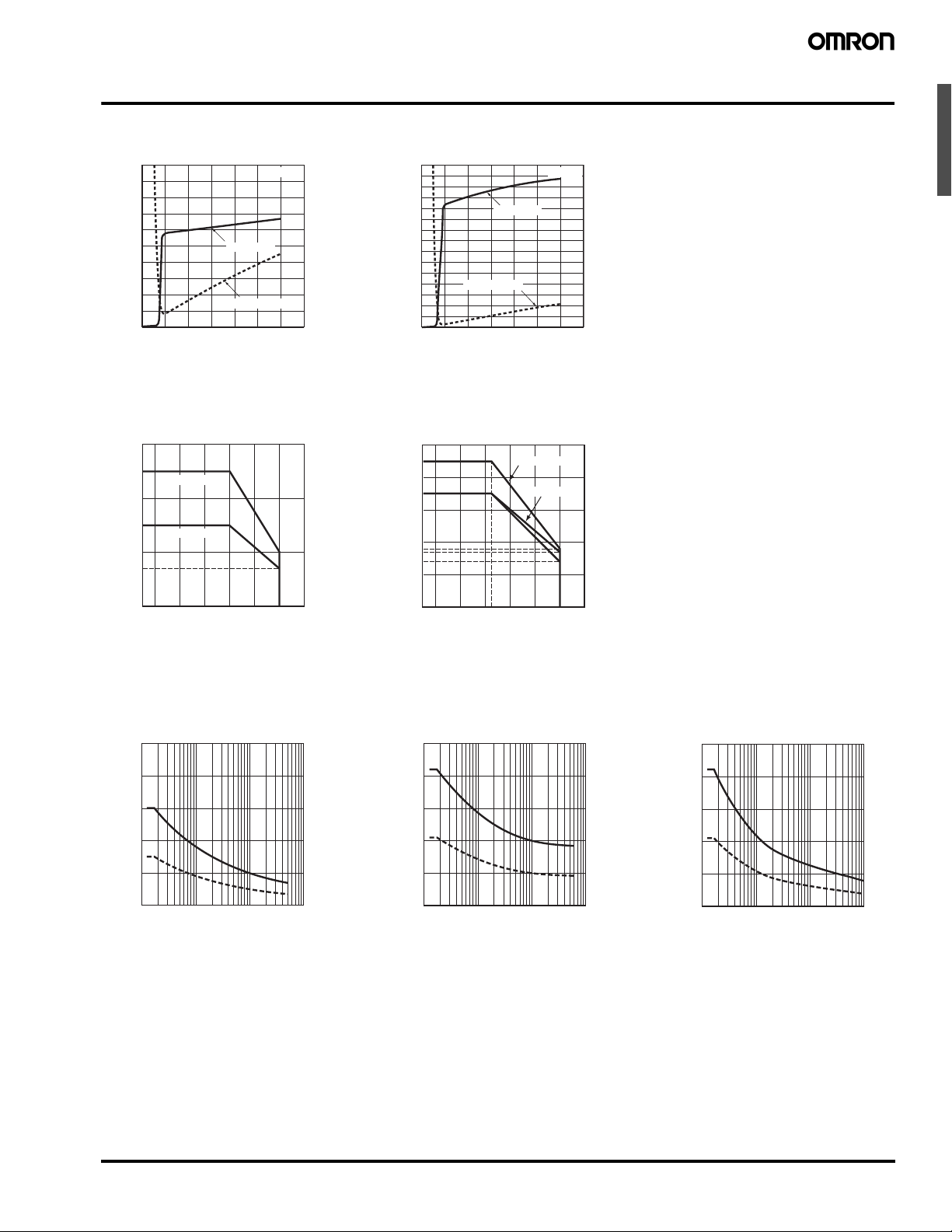
Input Voltage vs. Input Impedance and Input Voltage vs. Input Current
G3PE-2@@BG3PE-2@@BL
Load Current vs. Ambient Temperature
G3PE-215B(L), G3PE-225B(L) G3PE-235B(L), G3PE-245B(L)
30
25
G3PE-@25B(L)
Load current (A)
20
15
G3PE-@15B(L)
10
7
0
−30 −20
0 20 40 60 80 100
Ambient temperature (°C)
Inrush Current Resistivity: Non-repetitive
Make sure the inrush current stays below the dashed line curve if it occurs repetitively.
G3PE-215B(L) G3PE-225B(L)
250
200
150
Inrush current (A. Peak)
100
50
0
10 30 50
100
300 500 1,000 3,000 5,000
Energized time (ms)
Single-phase Solid State Relays for Heaters G3PE 447
G3PE-235B(L), G3PE-245B(L)
Page 4

Close Mounting (3 or 8 SSRs)
−40 −20 0 20 40 60 80 100
Ambient temperature (°C)
Load current (A)
5.7
20
15
13
12
10
5
0
3 Relays
8 Relays
−40 −20 0 20 40 60 80 100
8
30
25
20
19
15
5
10
7
0
Ambient temperature (°C)
Load current (A)
8 Relays
3 Relays
50
40
31
30
29
10
20
11
0
−40 −20
0 20 40 60 80 100
25
Ambient temperature (°C)
Load current (A)
8 Relays
3 Relays
DIN Track
G3PE-215B(L) G3PE-225B(L) G3PE-235B(L) G3PE-245B(L)
40
3 Relays
30
28
26
Load current (A)
8 Relays
20
11
10
0
−40 −20 0 20 40 60 80 100
25
Ambient temperature (°C)
Close Mounting Example
■ Approvals
UL Recognized, CSA Certified and EN60947-4-3 (TÜV) approved
448 Single-phase Solid State Relays for Heaters G3PE
Page 5

Dimensions
G3PE-215B(L)
G3PE-225B(L)
68
13.5
6
Two, M5
Two,
M3.5
Note: Without terminal cover.
4.6 dia.
4.6 × 5.6
elliptical hole
Note: With terminal cover.
90
±0.3
Three, 4.5 dia.
or M4
Mounting Holes
Terminal Arrangement/Internal Circuit Diagram
1
2
A1
A2
(+)
(−)
G3PE-5@@B
Output side
tiucric reggirT
Input side
ti
u
cr
ic
t
u
pn
I
1
2
A1
A2
(+)
(−)
G3PE-2@@B
Input side
Output side
tiucric reggirT
t
iu
cr
i
c t
u
pn
I
25
±0.3
(100)
(85)
(90)
100 max.
90
±0.2
84
25
±0.2
44.5 max.
24
G3PE-235B(L)
G3PE-245B(L)
Note: All units are in millimeters unless otherwise indicated.
Solid State Relays
Two, M4
100 max.
±0.3
13
Three, 4.5 dia.
or M4
24
Two,
M3.5
68
4.2
6.3
Note: Without terminal cover.
Mounting Holes
±0.3
90
±0.2
13
±0.2
90
84
4.6 × 5.6
elliptical hole
22.5 max.
Note: With terminal cover.
(100)
(85)
Two,
4.6 dia.
(90)
4.5
Terminal Arrangement/Internal Circuit Diagram
G3PE-5@@B
Output side
1
t i u c r i c r e g g i r T
2
G3PE-2@@B
(+)
A1
tiucric reggirT
t i
u
c r
i c
t
u
p n
I
Output side
A2
( − )
1
Input side
2
(+)
A1
t
iu
cr
i
c t
u
pn
I
Input side
A2
(−)
Single-phase Solid State Relays for Heaters G3PE 449
Page 6

Safety Precautions
Refer to Safety Precautions for All Solid State Relays.
!CAUTION
Minor electrical shock may occasionally occur.
Do not touch the G3PE terminal section (i.e., currentcarrying parts) while the power is being supplied.
Also, always attach the cover terminal.
The G3PE may rupture if short-circuit current flows.
As protection against accidents due to shortcircuiting, be sure to install protective devices, such
as fuses and no-fuse breakers, on the power supply
side.
Minor electrical shock may occasionally occur.
Do not touch the main circuit terminals on the SSR
immediately after the power supply has been turned
OFF. Shock may result due to the electrical charge
stored in the built-in snubber circuit.
Minor burns may occasionally occur.
Do not touch the SSR or the heatsink while the power
is being supplied or immediately after the power
supply has been turned OFF. The SSR and heatsink
become extremely hot.
Precautions for Safe Use
OMRON constantly strives to improve quality and reliability.
SSRs, however, use semiconductors, and semiconductors may
commonly malfunction or fail. In particular, it may not be possible to
ensure safety if the SSRs are used outside the rated ranges.
Therefore, always use the SSRs within the ratings. When using an
SSR, always design the system to ensure safety and prevent human
accidents, fires, and social harm in the event of SSR failure. System
design must include measures such as system redundancy,
measures to prevent fires from spreading, and designs to prevent
malfunction.
Transport
Do not transport the G3PE under the following conditions.
Doing so may result in damage, malfunction, or deterioration of performance characteristics.
• Conditions in which the G3PE may be subject to water.
• Conditions in which the G3PE may be subject to high temperature
or high humidity.
• Conditions in which the G3PE is not packaged.
Operating and Storage Environments
Do not use or store the G3PE in the following locations. Doing so
may result in damage, malfunction, or deterioration of performance
characteristics.
• Locations subject to rainwater or water splashes.
• Locations subject to exposure to water, oil, or chemicals.
• Locations subject to high temperature or high humidity.
• Do not store in locations subject to ambient storage temperatures
outside the range −30 to 100°C.
• Do not use in locations subject to relative humidity outside the
range 45% to 85%.
• Locations subject to corrosive gases.
• Locations subject to dust (especially iron dust) or salts.
• Locations subject to direct sunlight.
• Locations subject to shock or vibration.
Installation and Handling
• Do not block the movement of the air surrounding the G3PE or heat
sink. Abnormal heating of the G3PE may result in shorting failures
of the output elements or burn damage.
• Do not use the G3PE if the heat radiation fins have been bent by
being dropped. Doing so may result in malfunction due to a
reduction in the heat radiation performance.
• Do not handle the G3PE with oily or dusty (especially iron dust)
hands. Doing so may result in malfunction.
• Attach a heat sink or radiator when using an SSR. Not doing so
may result in malfunction due to a reduction in the heat radiation
performance.
Installation and Mounting
• Mount the G3PE in the specified direction. Otherwise excessive
heat generated by the G3PE may cause short-circuit failures of the
output elements or burn damage.
• Make sure that there is no excess ambient temperature rise due to
the heat generation of the G3PE. If the G3PE is mounted inside a
panel, install a fan so that the interior of the panel is fully ventilated.
• Make sure the DIN track is securely mounted. Otherwise, the
G3PE may fall.
• When mounting the heat sink, do not allow any foreign matter
between the heat sink and the mounting surface. Foreign matter
may cause malfunction due to a reduction in the heat radiation
performance.
• If the G3PE is mounted directly in a control panel, use aluminum,
steel plating, or similar material with a low heat resistance as a
substitute for a heat sink. Using the G3PE mounted in wood or
other material with a high heat resistance may result in fire or
burning due to heat generated by the G3PE.
Installation and Wiring
• Use wires that are suited to the load current. Otherwise, excessive
heat generated by the wires may cause burning.
• Do not use wires with a damaged outer covering.
Otherwise, it may result in electric shock or ground leakage.
• Do not wire any wiring in the same duct or conduit as power or
high-tension lines. Otherwise, inductive noise may damage the
G3PE or cause it to malfunction.
• When tightening terminal screws, prevent any non-conducting
material from becoming caught between the screws and the
tightening surface. Otherwise, excessive heat generated by the
terminal may cause burning.
• Do not use the G3PE with loose terminal screws. Otherwise,
excessive heat generated by the wire may cause burning.
• For the G3PE models with a carry current of 35 A or larger, use M5
crimp terminals that are an appropriate size for the diameter of the
wire.
• Always turn OFF the power supply before performing wiring. Not
doing so may cause electrical shock.
Installation and Usage
• Select a load within the rated values. Not doing so may result in
malfunction, failure, or burning.
• Select a power supply within the rated frequencies. Not doing so
may result in malfunction, failure, or burning.
• The G3PE provides a circuit to prevent photocoupler damage by
forcibly arcing the output element for surge voltages applied to the
load. The G3PE therefore cannot be used for motor loads. Doing
so may result in load motor malfunction.
450 Single-phase Solid State Relays for Heaters G3PE
Page 7

Precautions for Correct Use
Panel
Vertical
Direction
Mounted on a
vertical surface
Panel
Mounted on a
horizontal surface
Output Terminal Section for Three-phase Models
Output Terminal Section for Single-phase Models
Input Terminal Section
The SSR in operation may cause an unexpected accident.
Therefore it is necessary to test the SSR under the variety of
conditions that are possible.
necessary to consider differences in characteristics between
individual SSRs.
The ratings in this catalog are tested values in a temperature range
between 15°C and 30°C, a relative humidity range between 25% and
85%, and an atmospheric pressure range between 86 and 106 kPa.
It
will be necessary
to provide the above conditions as well as the load
conditions if the user wants to confirm the ratings of specific SSRs.
As for the characteristics
of the SSR, it is
Wiring
• When using crimp terminals, refer to the terminal clearances
shown below.
7 mm
13 mm
12 mm
M4 (15 A, 25 A)
M5 (35 A, 45 A)
Causes of Failure
• Do not drop the G3PE or subject it to abnormal vibration or shock
during transportation or mounting. Doing so may result in
deterioration of performance, malfunction, or failure.
• Tighten each terminal to the torque specified below. Improper
tightening may result in abnormal heat generation at the terminal,
which may cause burning.
Terminals Screw terminal diameter Tightening torque
Input terminals M3.5 0.59 to 1.18 N·m
Output
terminals
M4 0.98 to 1.47 N·m
M5 1.57 to 2.45 N·m
• Do not supply overvoltage to the input circuits or output circuits.
Doing so may result in failure or burning.
• Do not use or store the G3PE in the following conditions. Doing so
may result in deterioration of performance.
• Locations subject to static electricity or noise
• Locations subject to strong electric or magnetic fields
• Locations subject to radioactivity
Mounting
• The G3PE is heavy. Firmly mount the DIN Track and secure both
ends with End Plates for DIN Track mounting models. When
mounting the G3PE directly to a panel, firmly secure it to the panel.
Screw diameter: M4
Tightening torque: 0.98 to 1.47 N·m
15-A and 25-A Models 35-A and 45-A Models
10 mm 13 mm
12.4 mm
M4 (15 A, 25 A)
7.0 mm
12.9 mm
M5 (35 A, 45 A)
10 mm
M3.5
• Make sure that all lead wires are thick enough for the current.
• For three-element and two-element models, the output terminal will
be charged even when the Relay is OFF. Touching the terminal
may result in electric shock. To isolate the Relay from the power
supply, install an appropriate circuit breaker between the power
supply and the Relay.
Always turn OFF the power supply before wiring the Unit.
• Terminal L2 and terminal T2 of a 2-element model are internally
connected to each other. Connect terminal L2 to the ground
terminal of the power supply.
If terminal L2 is connected to a terminal other than the ground
terminal, cover all the charged terminals, such as heater terminals,
to prevent electric shock and ground faults.
Fuses
• Use a quick-burning fuse on the output terminals to prevent
accidents due to short-circuiting. Use a fuse with equal or greater
performance than those given in the following table.
Note: Make sure that the load current is 50% of the rated load current
when the G3PE is mounted horizontally.
For details on close mounting, refer to the related information
under performance characteristics.
Mount the G3PE in a direction so that the markings read naturally.
Recommended Fuse Capacity
Rated G3PE output
current
15 A G3PE@15B Series
25 A G3PE@25B Series
35 A G3PE@35B Series
45 A G3PE@45B Series
Applicable SSR
Fuse
(IEC 60269-4)
32 A
63 A
Single-phase Solid State Relays for Heaters G3PE 451
Page 8

EMC Connection
G3PE
Input Output
3 m max.
Load
Recommended Capacitor (Film Capacitor)
G3PE-2@@B Series: 1 μF, 250 VAC
G3PE-5@@B Series: 0.5 μF, 500 VAC
Make EMC connections according to the following figure.
• Connect a capacitor to the load power supply.
• The input cable must be no longer than 3 m.
EMI
This is a Class A product (for industrial environments). In a domestic
environment, the G3PE may cause radio interference, in which case
the user may be required to take appropriate measures.
Noise and Surge Effects
If noise or an electrical surge occurs that exceeds the malfunction
withstand limit for the G3PE output circuit, the output will turn ON for
a maximum of one half cycle to absorb the noise or surge. Confirm
that turning the output ON for a half cycle will not cause a problem for
the device or system in which the G3PE is being used prior to actual
use. The G3PE malfunction withstand limit is shown below.
• Malfunction withstand limit (reference value): 500 V
Note: This value was measured under the following conditions.
Noise duration: 100 ns and 1 μs
Repetition period: 100 Hz
Noise application time: 3 min
Mounting to Control Panel
The G3PE is heavy. Firmly mount the DIN track and secure both
ends with End Plates for DIN-track-mounting models. When mounting the G3PE directly to a panel, firmly secure it to the panel.
If the panel is airtight, heat from the SSR will build up inside, which
may reduce the current carry ability of the SSR or adversely affect
other electrical devices. Be sure to install ventilation holes on the top
and bottom of the panel.
SSR Mounting Pitch (Panel Mounting)
• Single-phase Model
Duct or other object blocking airflow
Between duct and
G3PE
60 mm min.
Between duct and
G3PE
30 mm min.
Mounting direction
Vertical Direction
Host and slave
80 mm min.
SSR
10 mm min.
Mounting Models with Externally Attached Heat Sinks
• Before attaching an external Heat Sink or Radiator to the Unit,
always apply silicone grease, such as Toshiba Silicone's YG6260
or Sinetsu Silicone's G746, to the mounting surface to enable
proper heat radiation.
• Tighten the screws to the following torque to secure the Unit and
external Heat Sink or Radiator to enable proper heat dissipation.
Tightening torque: 2.0 N·m
452 Single-phase Solid State Relays for Heaters G3PE
Page 9

Relationship between the G3PE and Ducts or Other
SSR
Air inlet
Be aware of airflow
Ventilation
outlet
(Axial Fan)
SSR
SSR
Duct or other object blocking airflow
Objects Blocking Airflow
Incorrect Example Countermeasure 1 Countermeasure 2
Duct or other object
blocking airflow
50 mm max.
Duct
(No more
than 1/2
the SSR
depth is
recommended.)
Duct
Airflow
Mounting surface
SSR SSR
If the depth direction of
the G3PE is obstructed by
ducts, the heat radiation
will be adversely affected.
Duct Duct Duct
Vertical
Direction
Mounting surface
Use ducts that have a
shallow depth, to provide
a sufficient ventilation
area.
Base
Mounting surface
If the ducts cannot be made
lower, place the G3PE on a
metal base so that it is not
surrounded by the ducts.
SSR
Ventilation Outside the Control Panel
Note: 1. If the air inlet or air outlet has a filter, clean the filter regularly
to prevent it from clogging to ensure an efficient flow of air.
2. Do not locate any objects around the air inlet or air outlet,
otherwise the objects may obstruct the proper ventilation of
the control panel.
3. A heat exchanger, if used, should be located in front of the
G3PE to ensure the efficiency of the heat exchanger.
G3PE Ambient Temperature
15A and 25A models have ambient temperature of 40°C, while 35A
and 45A models have 25°C ambient Temperature. The G3PE uses a
semiconductor to switch the load. This causes the temperature inside
the control panel to increase due to heating resulting from the flow of
electrical current through the load. The G3PE reliability can be
increased by adding a ventilation fan to the control panel to dispel
this heat, thus lowering the ambient temperature of the G3PE.
(Arrhenius's law suggests that life expectancy is doubled by each
10°C reduction in ambient temperature.)
SSR rated current (A) 15 A 25 A 35 A 45 A
Required number of
fans per SSR
0.23 0.39 0.54 0.70
Example: For 10 G3PE SSRs with load currents of 15 A,
Note: 1. Size of fans: 92 mm × 92 mm, Air volume: 0.7 m
0.23 × 10 = 2.3
Thus, 3 fans would be required.
3
Ambient temperature of control panel: 30°C
2. If there are other instruments that generate heat in the
/min,
control panel in addition to SSRs, more ventilation will be required.
3. Ambient temperature: The temperature that will allow the
SSR to cool by convection or other means.
Single-phase Solid State Relays for Heaters G3PE 453
Page 10

OMRON ON-LINE
Global - http://www.omron.com
USA - http://www.components.omron.com
Cat. No. X301-E-1b
Printed in USA
OMRON ELECTRONIC
COMPONENTS LLC
55 E. Commerce Drive, Suite B
Schaumburg, IL 60173
847-882-2288
09/11 Specifications subject to change without notice
All sales are subject to Omron Electronic Components LLC standard terms and conditions of sale, which
can be found at http://www.components.omron.com/components/web/webfiles.nsf/sales_terms.html
ALL DIMENSIONS SHOWN ARE IN MILLIMETERS.
To convert millimeters into inches, multiply by 0.03937. To convert grams into ounces, multiply by 0.03527.
Single-phase Solid State Relays for Heaters G3PE
 Loading...