

Page 1
Solid State Relays with Failure Detection Function G3PC J-59
SSR
Solid State Relays with Failure Detection Function
G3PC
Detects failures in SSR used for heater
temperature control and simultaneously
outputs alarm signal. This SSR supports the
safe design of heater control systems, and
contributes to maintenance improvements
by the user.
• Main detection items:
SSR short-circuits and SSR open-circuits
• Alarm output possible to NPN/PNP-input devices.
• The failure-detection function is built-in and power is supplied
from the main circuit power supply making wiring simple.
• Slim design (width: 22.5 mm) incorporating a heat sink.
• In addition to screw mounting, DIN track mounting is also
possible.
• Certified by EC, UL, and CSA.
Model Number Structure
■ Model Number Legend
1. Basic Model Name
G3PC: SSR with Failure Detection Function
2. Rated Load Power Supply Voltage
2: 100 to 240 VAC
3. Rated Load Current
20: 20 A (carry current)
4. Terminal Type
B: Screw terminals
5. Certification
VD: Certified by UL, CSA, and VDE
Ordering Information
■ List of Models
Note: When ordering, specify the rated input voltage.
■ Accessories (Order Separately)
123 4 5
G3PC-@@@-@
Insulation method Zero cross function Indicators Rated output load Model number
Phototriac coupler Yes Yes
(See page 64)
20 A, 100 to 240 VAC
(resistive load: AC, Class1)
G3PC-220B-VD
Name Dimensions Model number
Mounting Track 50 cm (l) × 7.3 mm (t) PFP-50N
1 m (l) × 7.3 mm (t) PFP-100N
1 m (l) × 16 mm (t) PFP-100N2
Page 2
J-60 Solid State Relays with Failure Detection Function G3PC
Specifications
■ Ratings (at an Ambient Temperature of 25°C)
Detection Power Supply
Operating Circuit
Main Circuit
Alarm Output
■ Characteristics
Rated power supply voltage 100 to 240 VAC (50/60 Hz)
Operating voltage range 75 to 264 VAC (50/60 Hz)
Current consumption 15 mA AC max. (at 200 VAC)
Input method Voltage input
Rated input voltage 12 to 24 VDC
Operating input voltage
range
9.6 to 30 VDC
Must operate voltage 9.6 VDC max.
Must release voltage 1 VDC min.
Input current 7 mA DC max. (at rated input voltage)
Rated load voltage 100 to 240 VAC (50/60 Hz)
Operating voltage range 75 to 264 VDC (50/60 Hz)
Rated carry current 20 A (Ta = 40)
Minimum load current 0.1 A
Inrush current resistance (peak value) 220 A (60 Hz, 1 cycle)
Permissible (I2t) 260 A2s
Applicable load
(with Class-1 AC resistive load)
4 kW (at 200 VAC)
Output OFF collector voltage 30 VDC max.
Maximum carry current 0.1 A
Output form Independent NPN open collector
Operate time 1/2 of load power source cycle + 1 ms max.
Release time 1/2 of load power source cycle + 1 ms max.
Main circuit Output ON voltage drop 1.6 V rms max.
OFF leakage current 10 mA max. (at 200 VAC)
Alarm output Output ON voltage drop 1.5 V max.
OFF leakage current 0.1 mA max.
Insulation resistance 100 MΩ min. (at 500 VDC)
Dielectric strength 2,500 VAC, 50/60 Hz for 1 min
Vibration resistance Destruction: 10 to 55 to10 Hz, 0.35-mm single amplitude
Shock resistance
Destruction: 294 m/s
2
Ambient temperature Operating: -20 to 60°C (with no icing or condensation)
Storage: -30 to 70°C (with no icing or condensation)
Ambient humidity 45% to 85%
Weight Approx. 300 g
Certified standards UL508, CSA22.2 No. 14, EN60947-4-3 (IEC947-4-3); Certified by VDE
EMC Emission EN55011 Group 1 Class B
Immunity ESD IEC947-4-3, EN61000-4-2
4 kV contact discharge
8 kV air discharge
Immunity Electromagnetic IEC947-4-3, EN61000-4-3
10 V/m (80 MHz to 1 GHz)
Immunity EFT IEC947-4-3, EN61000-4-4
2 kV AC power-signal line
Immunity Surge transient IEC947-4-3, EN61000-4-5
2 kV
Immunity RF disturbance IEC947-4-3, EN61000-4-6
10 V (0.15 to 80 MHz)
Immunity Dips IEC947-4-3, EN61000-4-11
Page 3
Solid State Relays with Failure Detection Function G3PC J-61
SSR
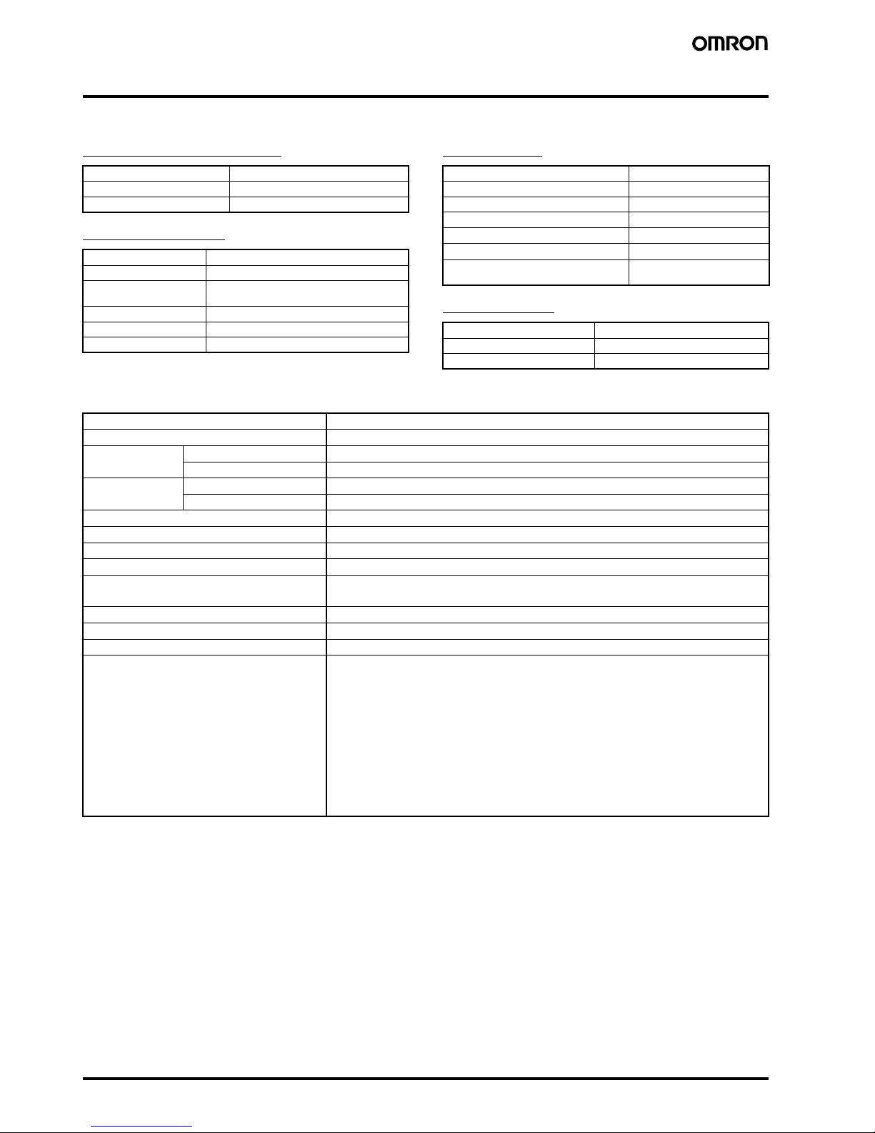
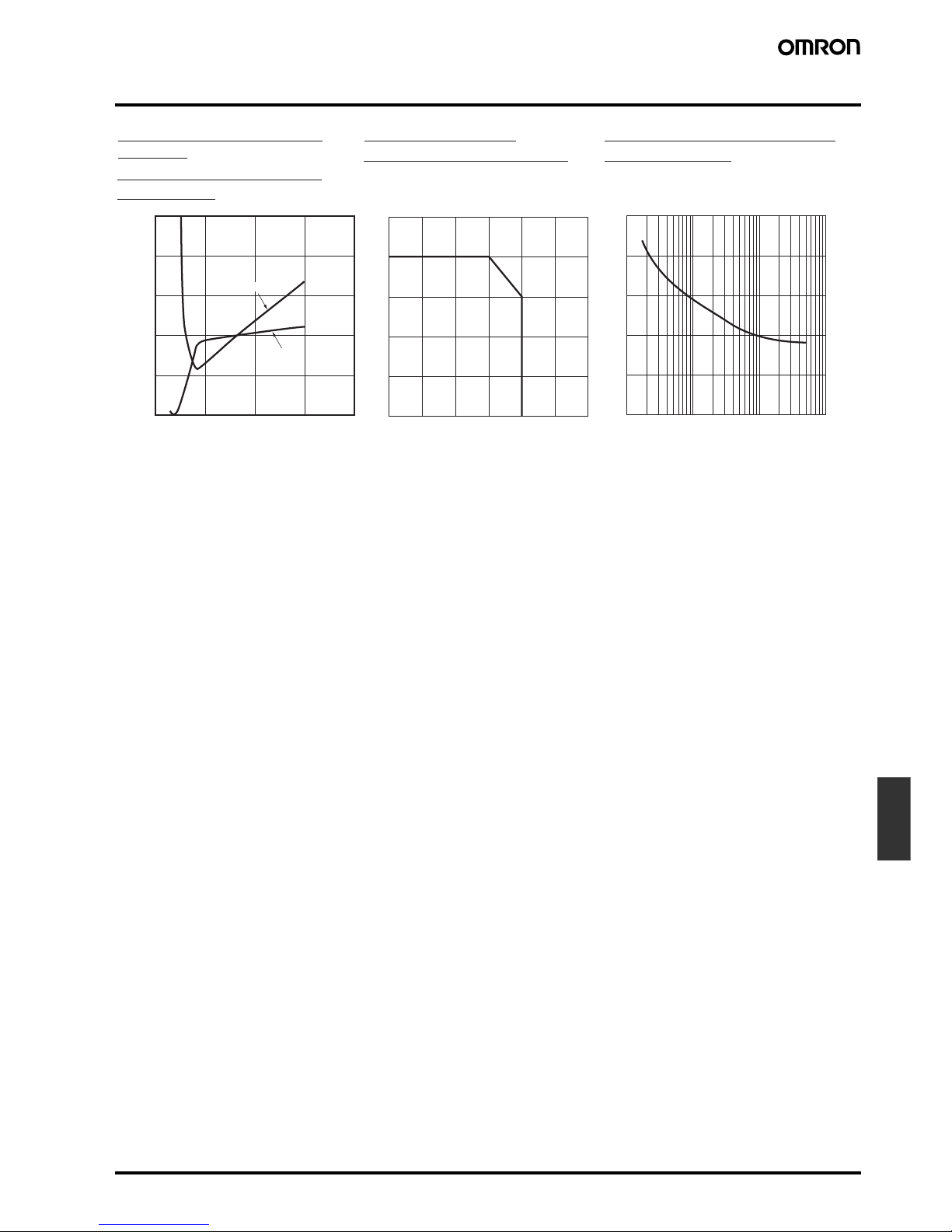
Engineering Data
0
2
4
6
8
10
25
20
15
10
5
0
10 20 30 40
-20 0 20 40 60 80 100
10 30 50 100 300 500 1,000 3,000 5,000
0
50
100
150
200
250
The figure will be less than 1/2 the rated
value for repetitive input.
One Cycle Surge Current:
Non-repetitive
Load Current vs.
Ambient Temperature
Input Voltage vs. Input
Current
Input Voltage vs. Input
Impedance
Input impedance (k
Ω
)
Input current (mA)
Load current (A)
Inrush current (A. Peak)
Ta = +25°C
Input impedance
Input current
Energized time (ms)
Ambient temperature (˚C)
Input voltage (V)
Page 4

J-62 Solid State Relays with Failure Detection Function G3PC
Operation
■ Failure Detection Function
Conditions for SSR Failure Detection
Note: 1. The contents of each of the above failure modes is as follows:
SSR short-circuit: SSR output circuit remains in the ON state.
SSR half-wave short-circuit: SSR output circuit remains in the ON state in one direction.
SSR open-circuit: SSR output circuit remains in the OFF state.
SSR half-wave open-circuit: SSR output circuit remains in the OFF state in one direction.
In addition to the failure modes listed above, detection of circuit disconnections for the load circuit is also possible. (As a rough guide,
circuit disconnection will be detected if the load impedance is greater than or equal to 1 MΩ.)
2. The same power supply is used for both the detection and for the output circuit and so detection is not performed during power
interruptions.
3. If power supply (terminal 3) is in the open state, the SSR will still turn ON and OFF in the same way but the failure detection function and
alarm display will not operate properly.
Connection Diagrams (Main Circuit)
The following diagrams show the applicable load connection configurations for SSR failure detection.
Note: 1. With 3-phase connection, so that the power supply voltage is applied between the G3PC’s terminals 1/L1 and 3, connect the desired
phase to terminal 3.
2. Above mentioned products are 200V only. They are not suitable for three-phase 400V, but for three-phase 220V only.
Timing Chart
Note: After failure detection, if the detection conditions differ to the conditions given under Conditions for SSR Failure Detection, alarm output is
reset.
Failure mode
(See note 1.)
Operating input (between
terminals A1 and A2)
Detection time Alarm display
(See note 3.)
Alarm display (between
terminals X1 and X2)
(See note 3.)
SSR short-circuit OFF 0.5 s max. (See note 2.) Red Open collector transistor
output
SSR half-wave short-circuit OFF
SSR open-circuit ON
SSR half-wave open-circuit ON
Single Phase 3-phase Star
Connection
3-phase Delta
Connection (3-phase,
2-wire Switching)
3-phase V
Connection
G3PC G3PC G3PC G3PC G3PC G3PC G3PC G3PC
Heater
Heater
Heater
Heate
r
Heater
Heater
Heater
Heater
Heater
Main circuit power
supply (load side)
Operating input
(between terminals
A1 and A2)
Input LED
(yellow)
Load current
RDY/ALM LED
(Green: ; Red: )
Alarm output
(between terminals
X1 and X2)
SSR ON normally SSR OFF normally SSR short-circuit Reset (See note.) SSR open-circuit Reset (See note.)
SSR failure detection
Circuit disconnection detection on the load side
Load circuit disconnection
Reset (See note.)
Page 5

Solid State Relays with Failure Detection Function G3PC J-63
SSR
Dimensions
G3PC-220B-VD
Accessories (Order Separately)
84.2
13.
5
6
8
90
0.2
80
8.5x3
90
0.3
1
3
0.3
Note The above diagram is
for wh
e
n the terminal
cover is o
pen.
Mounting Hole
s
Note The above diagram is
for wh
e
n the terminal
cove
r is clo
sed.
4.6x5.6 elliptic hol
e
130 max.
100 max
.
22.5 max
.
Terminal cover
Tow, 4.6 dia
.
Three, 4.5 dia. or M
4
4.5
15 251025
25 25
10
1,000 (500)
7.3±0.15
35±0.3
27±0.15
(see note)
15 (5)
1,000 (500)
35±0.3
27
24
29.2
1.5
1
16
4.5
25
25
10
15
1,000
25
25
15
10
1,000 (500)
(see note)
(see note)
Note Values in parentheses indicate dimensions for the
PFP-50N.
Mounting Tracks
PFP-100N, PFP-50N
PFP-100N2
1,000 (500)
(see note)
Page 6

J-64 Solid State Relays with Failure Detection Function G3PC
Installation
■ External Specifications
Terminal Arrangement
Indicators
Note: The same indicator is used as both the power supply indicator
and the alarm indicator.
Appearance
■ Connection Example
Note: 1. If the detection power supply terminal (terminal 3) is not connected, failure detection is not performed and so be sure to connect this
terminal.
2. If the load is connected to terminal 1/L1, failure detection may not operate correctly and so connect the load to terminal 2/T1.
3. With inductive loads (relay coil, etc.), connect back-current prevention diodes to both sides of the load.
Terminal name Terminal number Screw size
Main circuit terminals
(output)
1/L1, 2/T1 M4
Detection power supply terminal (input)
3
Operating circuit terminals (input)
A1, A2 M3.5
Alarm output terminals (output)
X1, X2
Name Symbol Color Meaning
Status indicators RDY Green SSR normal
ALM Red SSR failure detection
and circuit
disconnection
detection
Input indicator INPUT Yellow Operating
3
1/L1
A1(IN
+)
A2(IN
−)
X1(ALM
+)
X2(ALM
−)
2/T1
RDY/ALM
INPUT
1
3
2
X1
X2
(See note 1.)
(See note 2.)
Voltage output for Temperature
Controller, sequencer
12 to 24
VDC
30 VDC
min.
Input for Temperature
Controller, sequencer
Heater
L1
AC
IN
ALM
T1
A1
A2
Display Labels
Page 7

Solid State Relays with Failure Detection Function G3PC J-65
SSR
Safety Precautions
■ Precautions for Correct Use
Please observe the following precautions to prevent failure to
operate, malfunction, or undesirable effect on product performance.
Mounting Method
DIN Track Mounting
When mounting to a DIN track, mount the G3PC until it clicks into
place, otherwise it become loose during use and fall. Fix both ends
with end plates.
Panel Mounting
When mounting directly to a panel, observe the following conditions:
Screw diameter: M4
Tightening torque: 0.98 to 1.47 N·m
Vertical Mounting Horizontal Mounting
Note: Use the G3PC at a load current of 50% of the rated load current
when it is mounted horizontally.
Close Mounting
Note: Use the G3PC at a load current of 80% of the rated load current
when it is mounted side by side.
Wiring
• When using crimp terminals, observe the terminal clearances
shown below.
• Make sure that all lead wires are of a thickness appropriate for the
current.
• The output terminals are charged, and touching them may result in
electric shock, even when the G3PC is OFF. Separate the outputs
from the power supply by installing a circuit-breaker at a higher
level in the circuit.
Tightening Torque
Be sure to tighten the screws to the specified torques given below.
Not doing so may result in malfunction.
Panel
Vertical direction
Panel
5 mm
Wiring duct
80 mm min.
80 mm min.
Wiring duct
10 7.0
12.4
10
M3.5
Main Circuit Power Supply
(Terminals 1 to 3)
Operating Input/Alarm Output
(Terminals A1, A2, X1, and X2)
Terminal number Screw terminal
diameter
Tightening torque
A1, A2, X1, X2 M3.5 0.59 to 1.18 N·m
1/L1, 2/T1, 3 M4 0.98 to 1.47 N·m
Page 8

J-66 Solid State Relays with Failure Detection Function G3PC
In the interest of product improvement, specifications are subject to change without notice.
ALL DIMENSIONS SHOWN ARE IN MILLIMETERS.
To convert millimeters into inches, multiply by 0.03937. To convert grams into ounces, multiply by 0.03527.
Cat. No. J127-E1-03
 Loading...