

Page 1
Solid State Relays (Single-phase) G3PB 1
Solid State Relays (Single-phase)
G3PB
Compact, Slim-profile SSR with Heat Sink,
Offering Heater Control for 480-VAC Rated
Loads
• Compact design achieved by optimizing heat sink shape.
• DIN track mounting possible in addition to screw mounting.
• Conforms to CE Marking, EN (VDE approval), CSA, and VDE
standards.
(UL pending)
Note: Refer to Precautions on page 5.
Model Number Structure
■ Model Number Legend
1. Basic Model Name
G3PB: Solid State Relay
2. Rated Load Power Supply Voltage
5: 480 VAC
3. Rated Load Current
15: 15 A
25: 25 A
35: 35 A
45: 45 A
4. Termi nal Type
B: Screw terminals
5. Number of Elements
Blank: Single-phase models
6. Construction
Blank: DIN track mounting and built-in heat sink
7. Certification
VD: Certified by CSA and VDE
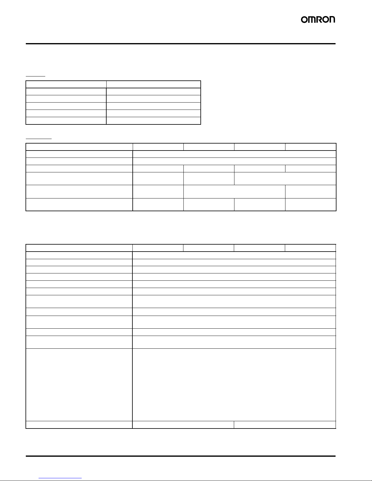
Ordering Information
■ List of Models
Note: The applicable load current varies depending on the ambient temperature. For details, refer to Load Current vs. Ambient Temperature in
Engineering Data.
■ Accessories (Order Separately)
1
234
56 7
G3PB-@@@-@@-@
Isolation method Zero cross
function
Operation
indicator
Rated input
voltage
Rated output load
(See note.)
Model number
Phototriac coupler Yes Yes (yellow) 12 to 24 VDC 15 A, 200 to 480 VAC G3PB-515B-VD 12 to 24 VDC
25 A, 200 to 480 VAC G3PB-525B-VD 12 to 24 VDC
35 A, 200 to 480 VAC G3PB-535B-VD 12 to 24 VDC
45 A, 200 to 480 VAC G3PB-545B-VD 12 to 24 VDC
Mounting Track 50 cm (1) x 7.3 mm (t) PFP-50N
1 m (1) x 7.3 mm (t) PFP-100N
1 m (1) x 16 mm (t) PFP-100N2
Page 2
2 Solid State Relays (Single-phase) G3PB
Specifications
■ Ratings (at an Ambient Temperature of 25°C)
Input
Output
Note: The applicable load current varies depending on the ambient temperature. For details, refer to Load Current vs. Ambient Temperature in
Engineering Data.
■ Characteristics
Item Common
Rated voltage 12 to 24 VDC
Operating voltage range 9.6 to 30 VDC
Rated input current 7 mA max.
Must operate voltage 9.6 VDC max.
Must release voltage 1 VDC min.
Item G3PB-515B-VD G3PB-525B-VD G3PB-535B-VD G3PB-545B-VD
Rated load voltage 200 to 480 VAC (50/60 Hz)
Load voltage range 180 to 528 VAC (50/60 Hz)
Applicable load current (See note.) 0.1 to 15 A (at 40
°C) 0.1 to 25 A (at 40°C) 0.5 to 35 A (at 25°C) 0.5 to 45 A (at 25°C)
Inrush current resistance (peak value) 150 A
(60 Hz, 1 cycle)
220 A
(60 Hz, 1 cycle)
440 A
(60 Hz, 1 cycle)
Permissible I
2
t
(half 60-Hz wave)
128 A2s 1,350 A2s 6,600 A2s
Applicable load
(with Class-1 AC resistive load)
6 kW max.
(at 400 VAC)
10 kW max.
(at 400 VAC)
14 kW max.
(at 400 VAC)
18 kW max.
(at 400 VAC)
Item G3PB-515B-VD G3PB-525B-VD G3PB-535B-VD G3PB-545B-VD
Operate time 1/2 of load power source cycle + 1 ms max.
Release time 1/2 of load power source cycle + 1 ms max.
Output ON voltage drop 1.8 V (RMS) max.
Leakage current 20 mA max. (at 480 VAC)
Insulation resistance 100 M
Ω min. (at 500 VDC)
Dielectric strength 2,500 VAC, 50/60 Hz for 1 min
Vibration resistance Destruction: 10 to 55 to 10 Hz, 0.375-mm single amplitude (0.75-mm double amplitude)
(Mounted to DIN track)
Shock resistance
Destruction: 294 m/s
2
(DIN track mounting)
Ambient temperature Operating:–30
°C to 80°C (with no icing or condensation)
Storage: –30
°C to 100°C (with no icing or condensation)
Ambient humidity Operating: 45% to 85%
Certified standards CSA22.2 No. 14
EN60947-4-3
EMC Emission EN55011 Group 1 Class B
Immunity ESD IEC947-4-3, EN61000-4-2
4 kV contact discharge
8 kV air discharge
Immunity Electromagnetic IEC947-4-3, EN61000-4-3
10 V/m (80 MHz to 1 GHz)
Immunity EFT IEC947-4-3, EN61000-4-4
2 kV AC power-signal line
Immunity Surge transient IEC947-4-3, EN61000-4-5
Normal mode
±1 kV, Common mode ±2 kV
Immunity RF disturbance IEC947-4-3, EN61000-4-6
10 V (0.15 to 80 MHz)
Immunity Dips IEC947-4-3, EN61000-4-11
Weight Approx. 240 g Approx. 400 g
Page 3
Solid State Relays (Single-phase) G3PB 3
Engineering Data
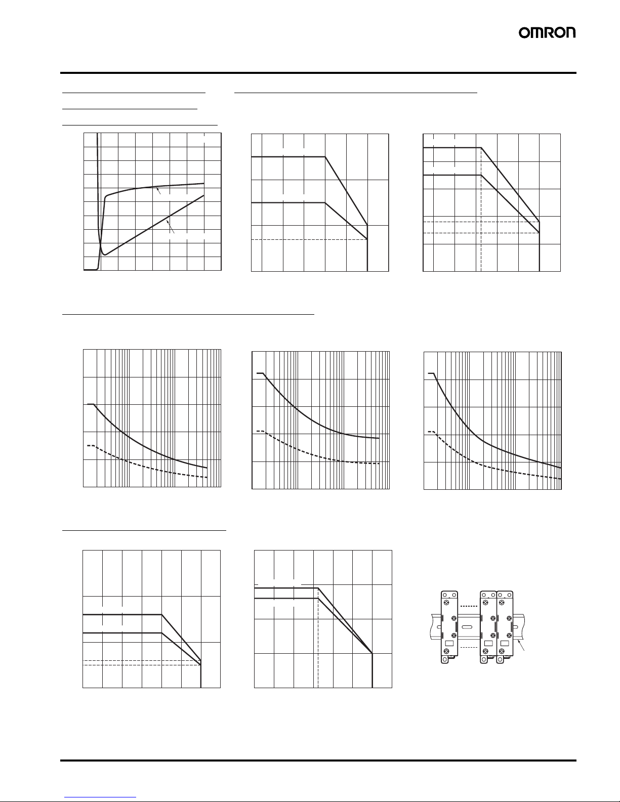
Input Voltage vs. Input
Impedance and Input
Voltage vs. Input Current
Load Current vs. Ambient Temperature
G3PB-515B-VD, G3PB-525B-VD G3PB-535B-VD, G3PB-545B-VD
One Cycle Surge Current: Non-repetitive
Keep the inrush current to below the inrush current resistance value (i.e., below the broken line) if it occurs repetitively.
G3PB-515B-VD G3PB-525B-VD G3PB-535B-VD, G3PB-545B-VD
Close Mounting (8 Relays)
G3PB-515B-VD, G3PB-525B-VD G3PB-535B-VD, G3PB-545B-VD
Input voltage (V)
Input Impedance
Ta = 25°C
10
9
8
7
6
5
4
3
2
1
0
5 10152025303540
Input current
Input impedance (k
Ω
)
Input current (mA)
30
25
20
15
10
7
0
−30 −20 0 20 40 60 80 10
0
G3PB-525B-VD
G3PB-515B-VD
Load current (A)
Ambient temperature (°C)
50
45
40
35
30
20
10
0
−30 −20 0 20 40 60 80 10
0
14
18
25
G3PB-545B-VD
G3PB-535B-VD
Ambient temperature (°C)
Load current (A)
250
200
150
100
50
0
Inrush current (A. Peak)
10 30 50 100 300 500 1,000 3,000 5,000
Energized time (ms)
Inrush current (A. Peak)
Energized time (ms)
250
200
150
100
50
0
10 30 50 100 300 500 1,000 3,000 5,000
Energized time (ms
)
Inrush current (A. Peak)
500
400
300
200
100
0
10 30 50 100 300 500 1,000 3,000 5,000
−40 −20 0 20 40 60 80 100
30
16
5
6
10
12
20
0
G3PB-525B-VD
G3PB-515B-VD
Ambient temperature (°C)
Load current (A)
−40 −20 0 20 40 60 80 100
40
30
29
26
20
10
0
G3PB-545B-VD
G3PB-535B-VD
25
Ambient temperature (˚C
)
Load current (A)
DIN Trac
k
Close Mounting Example
Page 4

4 Solid State Relays (Single-phase) G3PB
Dimensions
Note: All units are in millimeters unless otherwise indicated.
Accessories (Order Separately)
13
±
0.3
90
±
0.3
(−)
Three, 4.5 dia. or M4
Mounting Holes
Terminal Arrangement/
Internal Circuit Diagram
G3PB-515B-VD
G3PB-525B-VD
Output side
Input side
Note: Without terminal cover. Note: With terminal cover.
6.3
4.2
68 24
Two, M3.5
Two , M 4
13±
0.2
22.5 max.
100 max.
90
±
0.2
80
Two, 4.6 dia.
Elliptical hole: 4.6 x 5.6
(90)
(85)
(100)
1
2
A1
A2
(+)
Trigger circuit
Input circuit
(+)
(−)
G3PB-535B-VD
G3PB-545B-VD
Mounting Holes
Terminal Arrangement/
Internal Circuit Diagram
Output side
Input side
Note: Without terminal cover. Note: With terminal cover.
25
±
0.3
90
±
0.3
Two, 4.5 dia. or M4
68 24
13.4
6.1
Two, M3.5
Two , M 5
25
±
0.2
44.5 max.
100 max.
90
±
0.2
80
4.6 dia.
Elliptical hole: 4.6 x 5.6
(90)
(85)
(100)
1
2
A1
A2
Input circuit
Trigger circuit
PFP-100N, PFP-50N
PFP-100N2
35±0.3
4.5
7.3±0.15
27±0.15
35±
0.3
27
24
29.2
1.5
1
16
4.5
15
25
10
25
25
25
10
25
25
10
15
1,000
25
25
15
10
Mounting Tracks
Note: Values in parentheses indicate dimensions for the PFP-50N.
1,000 (500)
(see note)
15 (5)
(see note)
Page 5

Solid State Relays (Single-phase) G3PB 5
Safety Precautions
Touching the charged section may occasionally cause
minor electric shock. Do not touch the G3PB terminal
section (the charged section) when the power supply is
ON. Be sure to attach the cover before use.
The G3PB and heat sink will be hot and may occasionally cause minor burns. Do not touch the G3PB or the
heat sink either while the power supply is ON, or immediately after the power is turned OFF.
The internal snubber circuit is charged and may occasionally cause minor electric shock. Do not touch the
G3PB’s main circuit terminals immediately after the
power is turned OFF.
Be sure to conduct wiring with the power supply turned
OFF, and always attach the terminal cover after completing wiring. Touching the terminals when they are
charged may occasionally result in minor electric
shock.
Do not apply a short-circuit to the load side of the
G3PB. The G3PB may rupture. To protect against
short-circuit accidents, install a protective device, such
as a quick-burning fuse, on the power supply line.
■ Precautions for Safe Use
Although OMRON continuously strives to improve the quality and
reliability of our relays, the G3PB contains semiconductors, which
are generally prone to occasional malfunction and failure.
Maintaining safety is particularly difficult if a relay is used outside of
its ratings. Always use the G3PB within the rated values. When using
the G3PB, always design the system to ensure safety and prevent
human accidents, fires, and social damage even in the event of
G3PB failure, including system redundancy, measures to prevent
fires from spreading, and designs to prevent malfunction.
1. Do not apply voltage or current above the rated values to the
G3PB terminals. Doing so may cause G3PB malfunction or fire
damage.
2. Heat Dissipation
• Do not obstruct the airflow to the G3PB or heat sink. Heat gen-
erated from an G3PB error may occasionally cause the output
element to short, or cause fire damage.
• Be sure to prevent the ambient temperature from rising due to
the heat radiation of the G3PB. If the G3PB is mounted inside a
panel, install a fan so that the interior of the panel is fully ventilated.
• Be sure to install the G3PB using the specified mounting direction. Otherwise, heat generated from a G3PB error may cause
the output element to short or burn.
• Do not use the G3PB if heat dissipation fins have been bent as
a result of, for example, dropping the G3PB. If used in this state,
the SSR may be damaged due to the decreased heat dissipation capacity.
• When installing the G3PB directly into a control panel, use a
panel material with low thermal resistance, such as aluminum or
steel. If a material with high thermal resistance, such as wood,
is used, heat generated by the G3PB may cause fire or burning.
3. Perform wiring and tighten screws correctly, according to the following precautions. If wiring is incorrect or screws are not tightened sufficiently, the G3PB may be damaged by abnormal heat
generated when the power is turned ON.
• Make sure that all lead wires are appropriate for the load cur-
rent. Heat generated by a wiring error may result in burning.
• Do not operate if the screws on the output terminal are loose.
Heat generated by a terminal error may result in fire damage.
Wiring
• When using crimp terminals, refer to the terminal clearances
shown below.
• Output terminals are charged even when the Relay is turned
OFF. Touching the terminals may result in electric shock. To
isolate the Relay from the power supply, install an
appropriate circuit breaker between the power supply and
the Relay.
Tightening Torque
• Make sure that non-conducting materials are not caught when
tightening the terminal screws. Otherwise, the heat generated
from a terminal error may result in burning.
• Be sure to use M5 crimp terminals that are an appropriate size
for the wire diameter when wiring G3PB with a load current of
35 A min.
• Do not use wires with a damaged sheath. Doing so may result in
electric shock or a short circuit.
• Do not wire power lines or high-tension lines along with the lines
of the G3PB in the same conduit or duct. Doing so may result in
damage or malfunction due to induction.
• Use wires of an appropriate length. Wires of insufficient length
may result in malfunction, failure, or burning due to induction.
• Mount the DIN Track securely. Not doing so may cause the DIN
Tra c k to f a l l.
• Make sure that the G3PB clicks securely into place when it is
mounted to the DIN Track. Not doing so may cause the G3PB to
fall.
• Do not install the G3PB using hands that are dirty with oil or
metal dust. Doing so may result in a malfunction.
• Tighten the heat sink screws securely to a tightening torque of
0.98 to 1.47 N·m.
4. Usage Conditions
• Select a load within the rated values. Not doing so may result in
malfunction, failure, or burning.
• Use a power supply within the rated frequency range. Not doing
so may result in malfunction, failure, or burning.
5. Do not transport the G3PB under the following conditions. Doing
so may result in malfunction, failure, or deterioration of performance characteristics.
• When the G3PB is wet.
• During high temperatures or high humidity.
• When the G3PB is not packaged.
CAUTION
Section Screw terminal diameter Tightening torque
Input terminal M3.5 0.59 to 1.18 N·m
Output terminal M4 0.98 to 1.47 N·m
M5 1.47 to 2.45 N·m
10 mm 13 mm
12.9 mm
12.4 mm
M5M4
10 mm
7.0 mm
M3.5
15-A and
25-A Models
35-A and
45-A Models
Output Terminal Section
(Single-phase Models)
Input Terminal Section
Page 6

6 Solid State Relays (Single-phase) G3PB
6. Operating and Storage Locations
Do not use or store the G3PB in the following locations. Doing
so may result in damage, malfunction, or deterioration of
performance characteristics.
■ Precautions for Correct Use
Before Actual Operation
1. The G3PB in operation may cause an unexpected accident.
Therefore it is necessary to test the G3PB under the variety of
conditions that are possible. For example, the characteristics of
the G3PB must always be considered in terms of the differences
in characteristics between individual G3PBs.
2. Unless otherwise indicated, the rated values in this catalog have
all been tested according to JIS C5442 standards in a
temperature range between 15
°C and 30°C, a relative humidity
range between 25% and 85%, and an atmospheric pressure
range between 88 and 106 kPa. To confirm the ratings of specific
G3PBs, the same operating environment conditions must be provided in addition to the load conditions.
Mounting Method
Mount the DIN Track-mounting G3PBs firmly to the DIN Track and
secure End Plates on both sides to prevent the G3PB falling due to
its heavy weight. Also mount direct-mounting G3PBs securely in the
panel.
Note: Make sure that the load current is 50% of the rated load current
when the G3PB is mounted horizontally. For details on close
mounting, refer to the related information under performance
characteristics.
SSR Mounting Pitch
Panel Mounting
Relationship between SSRs and Ducts
Ventilation Outside the Control Panel
If the air inlet or air outlet has a filter, clean the filter regularly to
prevent it from clogging and ensure an efficient flow of air.
Do not locate any objects around the air inlet or air outlet, otherwise
the objects may obstruct the proper ventilation of the control panel.
A heat exchanger, if used, should be located in front of the SSR Units
to ensure the efficiency of the heat exchanger.
• Do not use or store in locations subject to direct sunlight.
• Do not use in locations subject to ambient temperatures
outside the range
−30 to 80°C.
• Do not use in locations subject to relative humidity
outside the range 45% to 85% or locations subject to
condensation as the result of severe changes in
temperature.
• Do not store in locations subject to ambient temperatures
outside the range
−30 to 100°C.
• Do not use or store in locations subject to corrosive or
flammable gases.
• Do not use or store in locations subject to dust (especially
iron dust) or salts.
• Do not use or store in locations subject to shock or vibration.
• Do not use or store in locations subject to exposure to
water, oil, or chemicals, or in locations subject to rain or
water drops.
• Do not use or store in locations subject to high temperatures or high humidity.
• Do not use or store in locations subject to static electricity
or noise.
• Do not use or store in locations subject to strong electric
or magnetic fields.
• Do not use or store in locations subject to radioactivity.
Vertical Mounting Horizontal Mounting
Vertical mounting
Panel
Panel
SSR
10 mm min.
Distance from duct:
30 mm min.
Distance from SSR:
80 mm min.
Distance from duct:
60 mm min.
Duct
Vertical direction
Airflow
Incorrect
Example
Countermeasure 1 Countermeasure 2
Duct
Duct
Duct
Duct Duct Duct
Vertical
direction
50 mm max.
Base
SSR SSR
SSR
100 mm
Do not surround the SSR
with ducts, otherwise
the heat radiation of the
SSR will be adversely
affected.
Use short ducts. If the ducts cannot be
shortened, place the
SSR on a metal
base so that it is not
surrounded by the
ducts.
Mounting surface
Mounting surface
Mounting surface
(A height of no
more than half
the SSR's
height is
recommended)
Air inlet
Be aware of air flow
Ventilation
outlet
(axial fan)
SSR
SSR
SSR
Duct
Page 7

Solid State Relays (Single-phase) G3PB 7
Please reduce the ambient temperature of SSRs.
The rated load current of an SSR is measured at an ambient
temperature of 25
°C or 40°C.
An SSR uses a semiconductor in the output element. This causes
the temperature inside the control panel to increase due to heating
resulting from the passage of electrical current through the load. To
restrict heating, attach a fan to the ventilation outlet or air inlet of the
control panel to ventilate the panel. This will reduce the ambient
temperature of the SSRs and thus increase reliability. (Generally,
each 10
°C reduction in temperature will double the expected life.)
Example: For 10 SSRs with load currents of 15 A,
0.23 × 10 = 2.3
Thus, 3 fans would be required.
Size of fans: 92 mm
2
, Air volume: 0.7 m3/min,
Ambient temperature of control panel: 30
°C
If there are other instruments that generate heat in the control
panel other than SSRs, additional ventilation will be required.
Operating Conditions
• Do not apply currents exceeding the rated current otherwise, the
temperature of the G3PB may rise excessively.
• Be sure to install protective devices on the power supply side, such
as fuses and non-fuse breakers, as protection against accidents
due to short-circuiting.
• Do not apply overvoltages to input or output circuits.
Doing so may cause Relay failure or burning.
EMC Directive Compliance
The G3PB complies with EMC Directives when capacitors and
varistors are used, as shown in the following diagram.
• The capacitor C1 must be connected between the input terminals
for G3PBs with DC inputs.
• The capacitor C2 must be connected to the load power supply
outputs.
• C1 and C2 must not be electrolytic capacitors.
• The varistor must be connected between the output terminals of
the G3PB.
• The input cable must be no longer than 3 m.
Loss Time
If the load power supply is used under a low voltage or current, the
loss time will increase. Before operating the G3PB, make sure that
this loss time will not cause problems.
Precautions on Operating and Storage Environments
1. Operating Ambient Temperature
The rated value for the ambient operating temperature of the G3PB
is for when there is no heat build-up. For this reason, under
conditions where heat dissipation is not good due to poor ventilation,
and where heat may build up easily, the actual temperature of the
G3PB may exceed the rated value resulting in malfunction or
burning.
When using the G3PB, design the system to allow heat dissipation
sufficient to stay below the Load Current vs. Ambient Temperature
characteristic curve. Note also that the ambient temperature of the
G3PB may increase as a result of environmental conditions (e.g.,
climate or air-conditioning) and operating conditions (e.g., mounting
in an airtight panel).
2. Transportation
Do not drop the G3PB or subject the G3PB to abnormal vibration or
shock during transport and installation. Doing so may result in
malfunction, failure, or deterioration of performance characteristics.
3. Vibration and Shock
Do not subject the G3PB to excessive vibration or shock. Otherwise
the SSR may malfunction and internal components may be
damaged.
To prevent the G3PB from abnormal vibration, do not install the SSR
in locations or by means that will subject it to vibration from other
devices, such as motors.
4. Solvents
Do not allow the G3PB to come in contact with solvents, such as
thinners or gasoline. Doing so will dissolve the markings on the
G3PB.
5. Oil
Do not allow the SSR terminal cover to come in contact with oil.
Doing so will cause the cover to crack and become cloudy.
Operation
1. Leakage Current
A leakage current flows through a snubber circuit in the G3PB even
when there is no power input. Therefore, always turn OFF the power
to the input or load and check that it is safe before replacing or wiring
the G3PB.
2. Screw Tightening Torque
Tighten the G3PB terminal screws to the rated torque. If the screws
are not tightened sufficiently, the G3PB may be damaged by heat
generated when the power is ON.
3. Installation
Do not install the G3PB using hands that are dirty with oil or metal
dust. Doing so may result in a malfunction.
4. Do Not Drop
Be careful not to drop the product during installation, mounting, or
otherwise handling the G3PB.
Load current (A) 15 A 25 A 35 A 45 A
Required number of fans
per SSR
0.23 0.39 0.54 0.70
Output
C1 C2Input
G3PB
Load
3 m max.
Capacitor C1
0.1
µ
F
Capacitor C2
0.5 µF, 500 VAC
Varistor
910 V, 0.6 W
Loss time
Input circuit
Trigger circuit
Switch element
Snubber circuit
Leakage
current
Varistor
Page 8

In the interest of product improvement, specifications are subject to change without notice.
ALL DIMENSIONS SHOWN ARE IN MILLIMETERS.
To convert millimeters into inches, multiply by 0.03937. To convert grams into ounces, multiply by 0.03527.
Cat. No. J152-E-01A
OMRON Corporation
Industrial Automation Company
Industrial Devices and Components Division H.Q.
Industrial Control Components Department
Shiokoji Horikawa, Shimogyo-ku,
Kyoto, 600-8530 Japan
Tel: (81)75-344-7119/Fax: (81)75-344-7149
Printed in Japan
0105
Warranty and Application Considerations
Read and Understand this Catalog
Please read and understand this catalog before purchasing the products. Please consult your OMRON representative if you have any
questions or comments.
Warranty and Limitations of Liability
WARRANTY
OMRON's exclusive warranty is that the products are free from defects in materials and workmanship for a period of one year (or other
period if specified) from date of sale by OMRON.
OMRON MAKES NO WARRANTY OR REPRESENTATION, EXPRESS OR IMPLIED, REGARDING NON-INFRINGEMENT,
MERCHANTABILITY, OR FITNESS FOR PARTICULAR PURPOSE OF THE PRODUCTS. ANY BUYER OR USER ACKNOWLEDGES
THAT THE BUYER OR USER ALONE HAS DETERMINED THAT THE PRODUCTS WILL SUITABLY MEET THE REQUIREMENTS
OF THEIR INTENDED USE. OMRON DISCLAIMS ALL OTHER WARRANTIES, EXPRESS OR IMPLIED.
LIMITATIONS OF LIABILITY
OMRON SHALL NOT BE RESPONSIBLE FOR SPECIAL, INDIRECT, OR CONSEQUENTIAL DAMAGES, LOSS OF PROFITS, OR
COMMERCIAL LOSS IN ANY WAY CONNECTED WITH THE PRODUCTS, WHETHER SUCH CLAIM IS BASED ON CONTRACT,
WARRANTY, NEGLIGENCE, OR STRICT LIABILITY.
In no event shall the responsibility of OMRON for any act exceed the individual price of the product on which liability is asserted.
IN NO EVENT SHALL OMRON BE RESPONSIBLE FOR WARRANTY, REPAIR, OR OTHER CLAIMS REGARDING THE PRODUCTS
UNLESS OMRON'S ANALYSIS CONFIRMS THAT THE PRODUCTS WERE PROPERLY HANDLED, STORED, INSTALLED, AND
MAINTAINED AND NOT SUBJECT TO CONTAMINATION, ABUSE, MISUSE, OR INAPPROPRIATE MODIFICATION OR REPAIR.
Application Considerations
SUITABILITY FOR USE
OMRON shall not be responsible for conformity with any standards, codes, or regulations that apply to the combination of products in
the customer's application or use of the products.
Take all necessary steps to determine the suitability of the product for the systems, machines, and equipment with which it will be used.
Know and observe all prohibitions of use applicable to this product.
NEVER USE THE PRODUCTS FOR AN APPLICATION INVOLVING SERIOUS RISK TO LIFE OR PROPERTY WITHOUT ENSURING
THAT THE SYSTEM AS A WHOLE HAS BEEN DESIGNED TO ADDRESS THE RISKS, AND THAT THE OMRON PRODUCTS ARE
PROPERLY RATED AND INSTALLED FOR THE INTENDED USE WITHIN THE OVERALL EQUIPMENT OR SYSTEM.
Disclaimers
PERFORMANCE DATA
Performance data given in this catalog is provided as a guide for the user in determining suitability and does not constitute a warranty.
It may represent the result of OMRON's test conditions, and the users must correlate it to actual application requirements. Actual
performance is subject to the OMRON Warranty and Limitations of Liability.
CHANGE IN SPECIFICATIONS
Product specifications and accessories may be changed at any time based on improvements and other reasons. Consult with your
OMRON representative at any time to confirm actual specifications of purchased product.
DIMENSIONS AND WEIGHTS
Dimensions and weights are nominal and are not to be used for manufacturing purposes, even when tolerances are shown.
 Loading...