

Omron G3NA-205B-UTU DC5-24, G3NA-210B-UTU AC100-120, G3NA-205B-UTU AC200-240, G3NA-210B-UTU DC5-24, G3NA-210B-UTU AC200-240 User Manual
...Page 1
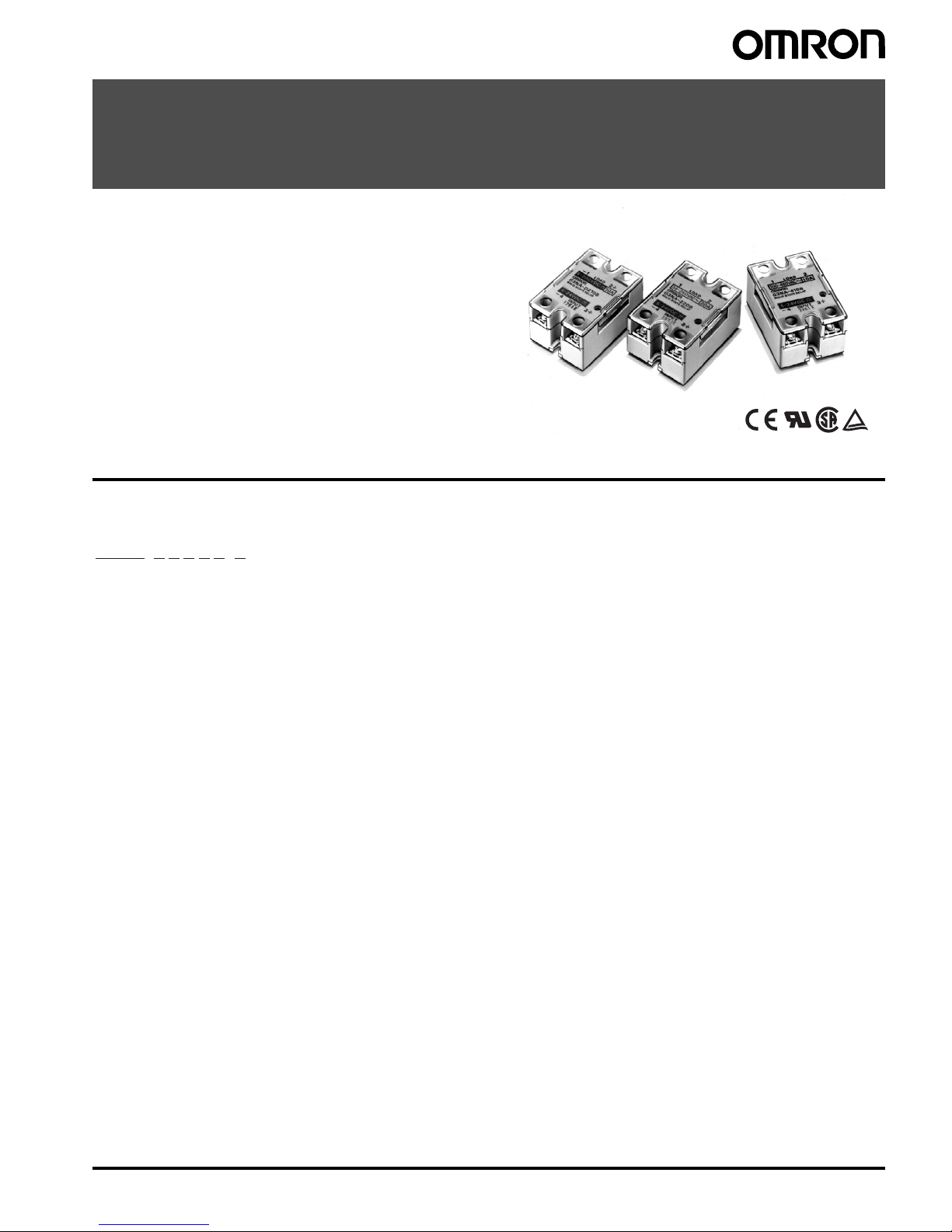
Solid State Relays G3NA 1
Solid State Relays
G3NA
The reliable choice for Hockey-puck-style
Solid State Relays. Available in a Wide
Range of Currents.
• All models feature the same compact dimensions to provide a
uniform mounting pitch.
• Built-in varistor effectively absorbs external surges.
• Operation indicator enables monitoring operation.
• Protective cover for greater safety.
• Certified by UL, CSA, and TÜV.
Model Number Structure
■ Model Number Legend
1. Basic Model Name
G3NA: Solid State Relay
2. Load Power Supply
Blank: AC output
D: DC output
3. Rated Load Power Supply Voltage
2: 200 VAC or 200 VDC
4: 400 VAC
4. Rated Load Current
Note: Not all combinations of current and voltage are available.
05: 5 A
10: 10 A
20: 20 A
25: 25 A
40: 40 A
50: 50 A
75: 75 A
90: 90 A
5. Termina l Ty pe
B: Screw terminals
6. Zero Cross Function
Blank: Equipped with zero cross function
(AC-output models only)
7. Certification
Blank: Models certified by UL and CSA
UTU: Certified by UL, CSA, and TÜV
1
2
3 4 5 6 7
G3NA-@@@@@-@
Page 2
2 Solid State Relays G3NA
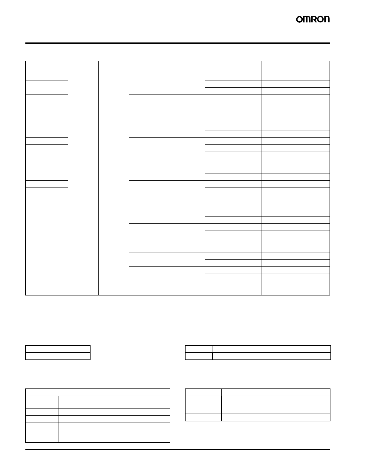
Ordering Information
■ List of Models
*All models are certified by UL, CSA, and TÜV.
Note: 1. The applicable output load depends on the ambient temperature. Refer to Load Current vs. Ambient Temperature in Engineering Data.
2. Loss time increases under 75 VAC. (Refer to page 13.) Confirm operation with the actual load.
■ Accessories (Order Separately)
One-touch Mounting Plates Mounting Bracket
Heat Sinks
Slim Models Enabling DIN-track Mounting Low-cost Models
Isolation Zero cross
function
Indicator Applicable output load
(See note 1.)
Rated input voltage Model
Phototriac Yes Yes 5 A at 24 to 240 VAC
(See note 2.)
5 to 24 VDC G3NA-205B-UTU DC5-24
Photocoupler 100 to 120 VAC G3NA-205B-UTU AC100-120
200 to 240 VAC G3NA-205B-UTU AC200-240
Phototriac 10 A at 24 to 240 VAC
(See note 2.)
5 to 24 VDC G3NA-210B-UTU DC5-24
Photocoupler 100 to 120 VAC G3NA-210B-UTU AC100-120
200 to 240 VAC G3NA-210B-UTU AC200-240
Phototriac 20 A at 24 to 240 VAC
(See note 2.)
5 to 24 VDC G3NA-220B-UTU DC5-24
Photocoupler 100 to 120 VAC G3NA-220B-UTU AC100-120
200 to 240 VAC G3NA-220B-UTU AC200-240
Phototriac 40 A at 24 to 240 VAC
(See note 2.)
5 to 24 VDC G3NA-240B-UTU DC5-24
Photocoupler 100 to 120 VAC G3NA-240B-UTU AC100-120
200 to 240 VAC G3NA-240B-UTU AC200-240
Phototriac 50 A at 24 to 240 VAC
(See note.)
5 to 24 VDC G3NA-250B-UTU DC5-24
Photocoupler 100 to 120 VAC G3NA-250B-UTU AC100-120
200 to 240 VAC G3NA-250B-UTU AC200-240
Phototriac 75 A at 24 to 240 VAC
(See note 2.)
5 to 24 VDC G3NA-275B-UTU DC5-24
Photocoupler 100 to 240 VAC G3NA-275B-UTU AC100-240
Phototriac 90 A at 24 to 240 VAC
(See note 2.)
5 to 24 VDC G3NA-290B-UTU DC5-24
Photocoupler 100 to 240 VAC G3NA-290B-UTU AC100-240
10 A at 200 to 480 VAC 5 to 24 VDC G3NA-410B-UTU DC5-24
100 to 240 VAC G3NA-410B-UTU AC100-240
25 A at 200 to 480 VAC 5 to 24 VDC G3NA-425B-UTU DC5-24
100 to 240 VAC G3NA-425B-UTU AC100-240
50 A at 200 to 480 VAC 5 to 24 VDC G3NA-450B-UTU DC5-24
100 to 240 VAC G3NA-450B-UTU AC100-240
75 A at 200 to 480 VAC
(See note 2.)
5 to 24 VDC G3NA-475B-UTU DC5-24
100 to 240 VAC G3NA-475B-UTU AC100-240
90 A at 200 to 480 VAC
(See note 2.)
5 to 24 VDC G3NA-490B-UTU DC5-24
100 to 240 VAC G3NA-490B-UTU AC100-240
--- 10 A at 5 to 200 VDC 5 to 24 VDC G3NA-D210B-UTU DC5-24
100 to 240 VAC G3NA-D210B-UTU AC100-240
Model
R99-12 FOR G3NA
Model Applicable SSR
R99-11 G3NA-240B-UTU, G3NA-250B-UTU, G3NA-450B-UTU
Model Applicable SSR
Y92B-N50 G3NA-205B-UTU, G3NA-210B-UTU,
G3NA-D210B-UTU, G3NA-410B-UTU
Y92B-N100 G3NA-220B-UTU, G3NA-425B-UTU
Y92B-N150 G3NA-240B-UTU, G3NA-250B-UTU
Y92B-P250 G3NA-450B-UTU
Y92B-P250NF G3NA-275B-UTU, G3NA-290B-UTU,
G3NA-475B-UTU, G3NA-490B-UTU
Model Applicable SSR
Y92B-A100 G3NA-205B-UTU, G3NA-210B-UTU,
G3NA-D210B-UTU, G3NA-220B-UTU,
G3NA-410B-UTU, G3NA-425B-UTU
Y92B-A150N G3NA-240-B-UTU
Page 3
Solid State Relays G3NA 3
Specifications
■ Ratings
Input (at an Ambient Temperature of 25°C)
Note: 1. The input impedance is measured at the maximum value of the rated supply voltage (for example, with the model rated at 100 to 120 VAC,
the input impedance is measured at 120 VAC).
2. With constant current input circuit system.
3. Refer to Temperature Characteristics (for Must Operate Voltage and Must Release Voltage) in Engineering Data for further details.
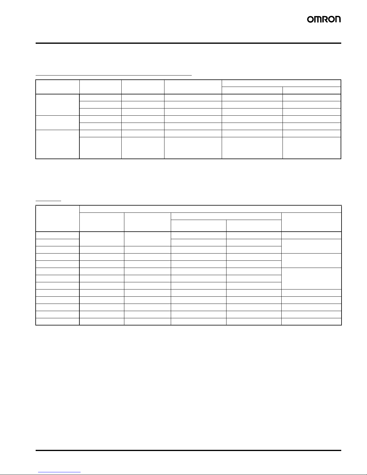
Output
Note: 1. The load current varies depending on the ambient temperature. Refer to Load Current vs. Ambient Temperature under Engineering Data.
2. When an OMRON Heat Sink (refer to Options) or a heat sink of the specified size is used.
Model Rated voltage Operating voltage Impedance
(See note 1.)
Voltage level
Must operate voltage Must release voltage
G3NA-2@@B-UTU 5 to 24 VDC 4 to 32 VDC 15 mA max. (See note 2.) 4 VDC max. 1 VDC min.
100 to 120 VAC 75 to 132 VAC 36 k
Ω±20% 75 VAC max. (See note 3.) 20 VAC min. (See note 3.)
200 to 240 VAC 150 to 264 VAC 72 k
Ω±20% 150 VAC max. (See note 3.) 40 VAC min. (See note 3.)
G3NA-4@@B-UTU 5 to 24 VDC 4 to 32 VDC 7 mA max. (See note 2.) 4 VDC max. 1 VDC min.
100 to 240 VAC 75 to 264 VAC 72 k
Ω±20% 75 VAC max. 20 VAC min.
G3NA-275B-UTU
G3NA-290B-UTU
G3NA-475B-UTU
G3NA-490B-UTU
G3NA-D210B-UTU
5 to 24 VDC 4 to 32 VDC 15 mA max. (See note 2.) 4 VDC max. 1 VDC min.
100 to 240 VAC 75 to 264 VAC 72 k
Ω±20% 75 VAC max. 20 VAC min.
Model Applicable load
Rated load voltage Load voltage range Load current (See note 1.) Inrush current
With heat sink
(See note 2.)
Without heat sink
G3NA-205B-UTU 24 to 240 VAC 19 to 264 VAC 0.1 to 5 A (at 40
°C) 0.1 to 3 A (at 40°C) 60 A (60 Hz, 1 cycle)
G3NA-210B-UTU 0.1 to 10 A (at 40
°C) 0.1 to 4 A (at 40°C) 150 A (60 Hz, 1 cycle)
G3NA-410B-UTU 200 to 480 VAC 180 to 528 VAC 0.2 to 10 A (at 40
°C) 0.2 to 4 A (at 40°C)
G3NA-220B-UTU 24 to 240 VAC 19 to 264 VAC 0.1 to 20 A (at 40
°C) 0.1 to 4 A (at 40°C) 220 A (60 Hz, 1 cycle)
G3NA-425B-UTU 200 to 480 VAC 180 to 528 VAC 0.2 to 25 A (at 40
°C) 0.2 to 4 A (at 40°C)
G3NA-240B-UTU 24 to 240 VAC 19 to 264 VAC 0.1 to 40 A (at 40
°C) 0.1 to 6 A (at 40°C) 440 A (60 Hz, 1 cycle)
G3NA-250B-UTU 24 to 240 VAC 19 to 264 VAC 0.1 to 50 A (at 40
°C) 0.1 to 6 A (at 40°C)
G3NA-450B-UTU 200 to 480 VAC 180 to 528 VAC 0.2 to 50 A (at 40
°C) 0.2 to 6 A (at 40°C)
G3NA-275B-UTU 24 to 240 VAC 19 to 264 VAC 1 to 75 A (at 40
°C) 1 to 7 A (at 40°C) 800 A (60 Hz, 1 cycle)
G3NA-475B-UTU 200 to 480 VAC 180 to 528 VAC 1 to 75 A (at 40
°C) 1 to 7 A (at 40°C) 800 A (60 Hz, 1 cycle)
G3NA-290B-UTU 24 to 240 VAC 19 to 264 VAC 1 to 90 A (at 40
°C) 1 to 7 A (at 40°C) 1,000 A (60 Hz, 1 cycle)
G3NA-490B-UTU 200 to 480 VAC 180 to 528 VAC 1 to 90 A (at 40
°C) 1 to 7 A (at 40°C) 1,000 A (60 Hz, 1 cycle)
G3NA-D210B-UTU 5 to 200 VDC 4 to 220 VDC 0.1 to 10 A (at 40
°C) 0.1 to 4 A (at 40°C) 20 A (10 ms)
Page 4
4 Solid State Relays G3NA
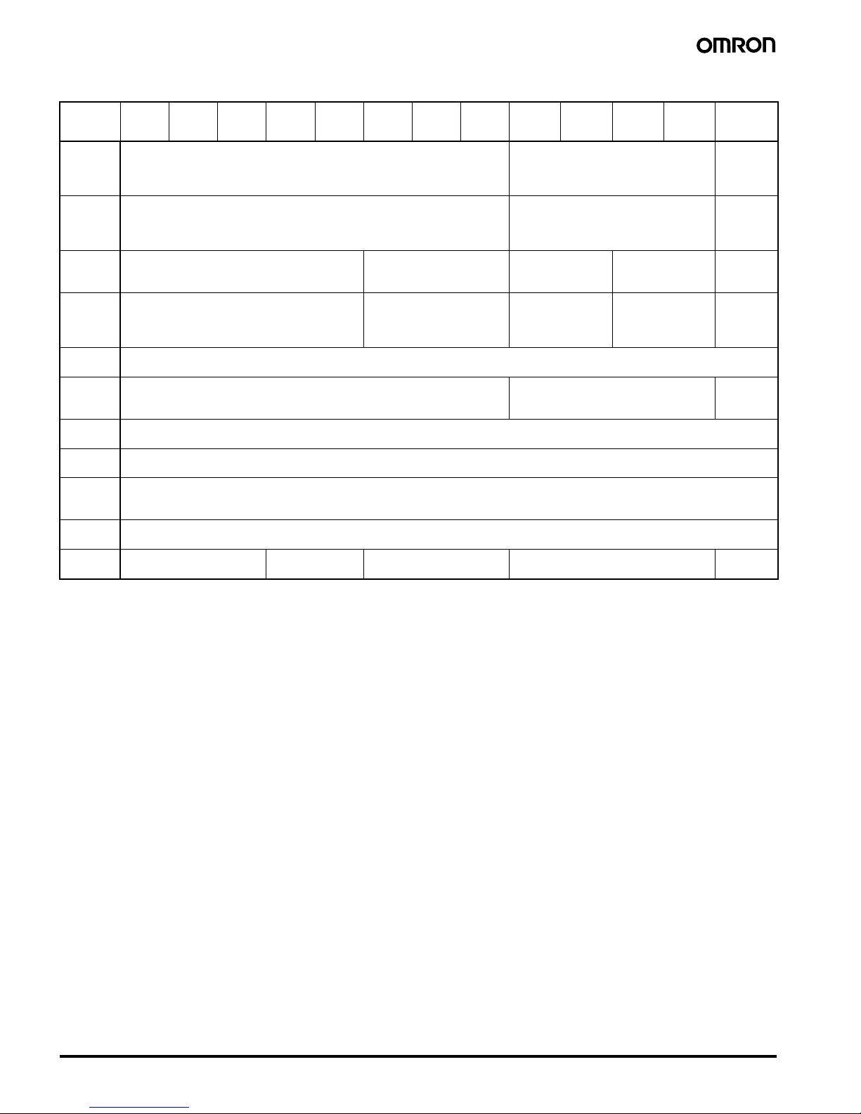
■ Characteristics
Item G3NA-
205B-
UTU
G3NA-
210B-
UTU
G3NA-
220B-
UTU
G3NA-
240B-
UTU
G3NA-
250B-
UTU
G3NA-
410B-
UTU
G3NA-
425B-
UTU
G3NA-
450B-
UTU
G3NA-
275B-
UTU
G3NA-
290B-
UTU
G3NA-
475B-
UTU
G3NA-
490B-
UTU
G3NA-
D210B-
UTU
Operate
time
1/2 of load power source cycle + 1 ms max. (DC input)
3/2 of load power source cycle + 1 ms max. (AC input)
1/2 of load power source cycle + 1 ms
max. (DC input)
3/2 of load power source cycle + 1 ms
max. (AC input)
1 ms max.
(DC input)
30 ms max.
(AC input)
Release
time
1/2 of load power source cycle + 1 ms max. (DC input)
3/2 of load power source cycle + 1 ms max. (AC input)
1/2 of load power source cycle + 1 ms
max. (DC input)
3/2 of load power source cycle + 1 ms
max. (AC input)
5 ms max.
(DC input)
30 ms max.
(AC input)
Output ON
voltage
drop
1.6 V (RMS) max. 1.8 V (RMS) max. 1.6 V (RMS) max. 1.8 V (RMS) max. 1.5 V max.
Leakage
current
5 mA max. (at 100 VAC)
10 mA max. (at 200 VAC)
10 mA max. (at 200 VAC)
20 mA max. (at 400 VAC)
5 mA max.
(at 100 VAC)
10 mA max.
(at 200 VAC)
10 mA max.
(at 200 VAC)
20 mA max.
(at 400 VAC)
5 mA max.
(at
200 VDC)
Insulation
resistance
100 M
Ω min. (at 500 VDC)
Dielectric
strength
2,500 VAC, 50/60 Hz for 1 min 4,000 VAC, 50/60 Hz for 1 min 2,500 VAC,
50/60 Hz
for 1 min
Vibration
resistance
Destruction: 10 to 55 to 10 Hz, 0.75-mm single amplitude (1.5-mm double amplitude)
Shock
resistance
Destruction: 1,000 m/s
2
Ambient
temperature
Operating:–30
°C to 80°C (with no icing or condensation)
Storage: –30
°C to 100°C (with no icing or condensation)
Ambient
humidity
Operating: 45% to 85%
Weight Approx. 60 g Approx. 70 g Approx. 80 g Approx. 120 g Approx.
70 g
Page 5
Solid State Relays G3NA 5
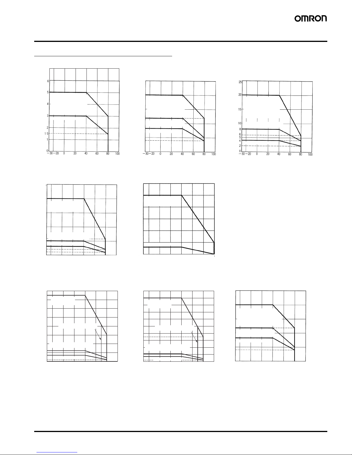
Engineering Data
Load Current vs. Ambient Temperature
Note: The ambient operating temperature of the Y92B-P250NF is −
30 to 70°C. Be sure the operating temperature is within this
range.
G3NA-205B-UTU G3NA-210B-UTU
G3NA-410B-UTU
G3NA-220B-UTU
G3NA-425B-UTU
20
16
10
8
6
5
4
2
0
Ambient temperature (°C)
Ambient temperature (°C)
Ambient temperature (°C)
Load current (A)
Load current (A)
Load current (A)
Without heat sink
Without heat sink
Without heat sink
With standard heat sink
(Y92B-A100 or Y92BN50) or aluminum plate
measuring 75 mm x
75 mm x t3.2 mm
(W x H x t)
With standard heat sink
(Y92B-A100 or Y92BN50) or aluminum plate
measuring 150 mm x
150 mm x t3.2 mm
(W x H x t)
With iron plate measuring
100 x 100 x t0.8 (W x H x t)
With standard heat sink
(Y92B-A100 or Y92BN100) or aluminum plate
measuring 200 mm x
200 mm x t3.2 mm
(W x H x t)
With iron plate measuring
100 x 100 x t0.8 (W x H x t)
G3NA-240B-UTU G3NA-250B-UTU
G3NA-450B-UTU
Load current (A)
Ambient temperature (°C)
With standard heat sink
(Y92B-P250)
Without heat sink
50
45
40
30
20
12
10
6
4
2
−30−20
0 20406080100
−20
0 20406080100
0
60
50
40
30
20
10
6
0
−30
Load current (A)
Ambient temperature (°C)
Without heat sink
With standard heat
sink (Y92B-A150N or
Y92B-N150)
With iron plate measuring
100 x 100 x t0.8 (W x H x t)
70
60
50
40
35
30
20
12
7
100
80
90
0
1008060 7040200
−20−30
2
4A
G3NA-275B-UTU
G3NA-475B-UTU
G3NA-290B-UTU
G3NA-490B-UTU
70
75
60
50
40
30
20
10
12
7
80
0
1008060 7040200−20−30
2
4A
G3NA-D210B-UTU
20
10
6
5
4
2
0
100806040200−20−30
Load current (A)
Ambient temperature (°C)
Load current (A)
Ambient temperature (°C)
Without heat sink
Without heat sink
With iron plate measuring
100 x 100 x t0.8 (W x H x t)
With iron plate measuring
100 x 100 x t0.8 (W x H x t)
0.6°C/W with
Heat Sink
Using the Y92B-P250NF
0.3°C/W with
Heat Sink
Using the Y92B-P250NF
Load current (A)
Ambient temperature (°C)
Without heat sink
With standard heat sink
(Y92B-A100 or Y92B-N50)
or aluminum plate measuring
150 mm x 150 mm x t3.2 mm
(W x H x t)
With iron plate measuring
100 x 100 x t0.8 (W x H x t)
Page 6

6 Solid State Relays G3NA
One Cycle Surge Current
The values shown by the solid line are for non-repetitive inrush currents.
Keep the inrush current below the values shown by the dotted line if it occurs repetitively.
Thermal Resistance Rth (Back of
Junction SSR) (Examples)
Thermal Resistance Rth of Heat Sinks
(Examples)
Note: When using a commercially available heat sink, use one with a
thermal resistance equal to or less that the OMRON Heat Sink.
60
40
20
0
5,0001,000500200100503010
Energized time (ms)
Inrush current (A peak)
150
100
50
0
5,0001,000500200100503010
Energized time (ms)
Inrush current (A peak)
200
150
100
50
0
5,0001,000500200100503010
Energized time (ms)
Inrush current (A peak)
400
300
200
100
0
5,0001,000500200100503010
Energized time (ms)
Inrush current (A peak)
G3NA-205B-UTU
G3NA-210B-UTU
G3NA-410B-UTU
G3NA-220B-UTU
G3NA-425B-UTU
G3NA-240B-UTU/250B-UTU
G3NA-450B-UTU
900
800
700
600
500
400
300
200
100
0
1,00010050 3003010
Energized time (ms)
Inrush current (A peak)
1,200
800
1,000
600
400
200
0
1,00010050 3003010
Energized time (ms)
Inrush current (A peak)
G3NA-275B-UTU
G3NA-475B-UTU
G3NA-290B-UTU
G3NA-490B-UTU
28
30
26
24
22
20
18
16
14
12
10
8
6
4
2
0
2,0001,000500200 30010050 70302010
Energized time (ms)
Inrush current (A peak)
G3NA-D210B
40
20
0
−20
−40
10
0
806040200−20−30
Ambient temperature (°C)
Variation rate (%)
3,000
2,000
1,000
700
500
300
200
100
70
50
30
20
242220181614121086420
Heat sink area (cm
2
)
Load current (A
)
Note: The heat sink area refers to the combined area
of the sides of the heat sink that radiate heat.
For example, when a current of 18 A is allowed
to flow through the SSR at 40°C, the graph
shows that the heat sink area is about 450 cm
2
.
Therefore, if the heat sink is square, one side of
the heat sink must be 15 cm ( ) or
longer.
Ambient
temperature 80°C
Aluminum plate
3.2 mm thick
Ambient
temperature 40°C
450 (cm2)/2
Temperature
Characteristics
(for Must Operate
Voltage and Must
Release Voltage)
Heat Sink Area
vs. Load Current
G3NA-2@@B-UTU AC input
G3NA-220B-UTU
Model Rth (°C/W)
G3NA-205B-UTU 3.22
G3NA-210B-UTU 2.62
G3NA-220B-UTU 1.99
G3NA-240B-UTU 0.45
G3NA-250B-UTU 0.45
G3NA-275B-UTU
G3NA-475B-UTU
G3NA-290B-UTU
G3NA-490B-UTU
0.45
G3NA-D210B-UTU 2.62
Model Rth (°C/W)
Y92B-N50 2.8
Y92B-N100 1.63
Y92B-N150 1.38
Y92B-A100 1.63
Y92B-A150N 1.37
Y92B-A250 1.00
Y92B-P250NF 0.46
Page 7

Solid State Relays G3NA 7
Dimensions
■ Relays
Note: All units are in millimeters unless otherwise indicated.
G3NA-205B-UTU, G3NA-210B-UTU, G3NA-220B-UTU, G3NA-410B-UTU, G3NA-425B-UTU
13.8
12
34
(−) (+)
4.5
25
47.5
44
47.6±0.2
25 max.
27 max.
Mounting Holes
Output
Input
Load
4.5 dia.
43 max.
58 max.
Operating
indicator
Four, M4 x 8
screws
Two, 4.3-dia.
or M4 holes
Terminal Arrangement/
Internal Connections
(Top View)
Load
power
supply
11.9
47.6
±0.2
12
34
(−) (+)
G3NA-240B-UTU, G3NA-250B-UTU, G3NA-450B-UTU
13.8
47.5
44
4.5
25
11.9
Mounting Holes
Output
Input
Load
25 max.
27 max.
58 min.
4.5 dia.
Two, M5 x 12 screws
43 max.
Tw o,
M 4 x 8
Operating
indicator
Two, 4.3-dia.
or M4 holes
Load
power
supply
Terminal Arrangement/
Internal Connections
(Top View)
G3NA-275B-UTU, G3NA-475B-UTU, G3NA-290B-UTU, G3NA-490B-UTU
16.8
47.5 44
25
8.2
12
4.5
47.6
±
0.2
12
(−)
4
(+)
3
Mounting Holes
Output
Input
Load
4.5 dia.
Two, M5 x 12
screws
Operating
indicator
Two, 4.3-dia.
or M4 holes
Terminal Arrangement/
Internal Connections
(Top View)
Load
power
supply
Two, M4 x
8 screws
43 max.
58 max.
26 max.
28 max.
G3NA-D210B-UTU
13.8
47.6±0.2
12
34
(−) (+)
− +
4.5
25
47.5 44
Note: The load can be connected to either the positive or negative side.
11.9
25 max.
27 max.
Mounting Holes
Output
Input
Load
4.5 dia.
43 max.
58 max.
Four, M4 x 8
screws
Operating
indicator
Two, 4.3-dia.
or M4 holes
Terminal Arrangement/
Internal Connections
(Top View)
Load
power
supply
Note: When connecting the load, either the
positive or negative side of the load
terminals can be connected.
Page 8

8 Solid State Relays G3NA
■ Options (Order Separately)
One-touch Mounting Plate
The One-touch Mounting Plate is used to mount the GN3A to a DIN
Tr ac k .
R99-12 FOR G3NA (for the G3NA and G3NE)
• When a Relay is mounted to DIN Track, use it within the rating for a
Relay without a heat sink.
• Use the following DIN Tracks: PFP-100N or PFP-100N2.
Mounting Bracket
Heat Sinks
30
44
Two, M4 mounting
holes for the G3NE
Two, M4 mounting
holes for the G3NA
To mount the Relay to DIN
Track, first mount it to the
One-touch Mounting Plate
and then attach it to the DIN
Track as shown in the
diagram.
To remove the Relay from
the DIN Track, pull down on
the tab with a screwdriver in
the direction of the arrow.
R99-11 (for the G3NA-240B-UTU, G3NA-250B-UTU, G3NA-450B-UTU)
4.6
5
6
21
12.5
16
8
4
5
Use Mounting Bracket R99-11 so that the G3NA-240B/-250B/-450B-UTU
can be mounted with the same pitch as that of the G3N-240B.
5.6
47.6
90±0.3
35
30.5±0.3
30
5
4.5
6
35±0.2
90±0.4
Mounting Holes
4.6 dia.
Two, M3 holes
Two, M4 holes
77 max.
100 max.
44 max.
47 max.
51 max.
Weight: approx. 200 g
Two, 3.2-dia. holes
Two, 4.4-dia.
or M4 holes
The orientation indicated by the external dimensions is not the correct mounting orientation. When opening mounting holes, refer to the
mounting hole dimensions.
For surface mounting, a 30% derating of the load current is required (from the Load Current vs. Ambient Temperature graphs).
Y92B-N50 Heat Sink (for the G3NA-205B-UTU, G3NA-210B-UTU, G3NA-410B-UTU, G3NA-D210B-UTU)
Page 9

Solid State Relays G3NA 9
Y92B-N100 Heat Sink (for the G3NA-220B-UTU, G3NA-425B-UTU)
35
30.5±0.3
47.6
90±0.3
5.6
5
4.5
28
13
35±0.2
30
The orientation indicated by the external dimensions is not the correct mounting orientation. When opening mounting holes, refer to the
mounting hole dimensions.
For surface mounting, a 30% derating of the load current is required (from the Load Current vs. Ambient Temperature graphs).
90±0.4
4.6 dia.
Two, M3 holes
77 max.
100 max.
71 max.
100 max.
75 max.
Two, 3.2-dia. holes
Mounting Holes
Weight: approx. 400 g
Two, M4
holes
Two, 4.4-dia.
or M4 holes
Y92B-N150 Heat Sink (for the G3NA-240B-UTU)
35
47.6
5.6 5 4.5
30
90±0.3
56±0.3
13
28
The orientation indicated by the external dimensions is not the correct mounting orientation. When opening mounting holes, refer to the
mounting hole dimensions.
For surface mounting, a 30% derating of the load current is required (from the Load Current vs. Ambient Temperature graphs).
4.6 dia.
77 max.
100 max.
100 max.
30
100 max.
Two, 3.2-dia. holes
104 max.
Mounting Holes
Weight: approx. 560 g
Two, 4.4-dia.
or M4 holes
Three,
M4 holes
Page 10

10 Solid State Relays G3NA
Y92B-P250 (for the G3NA-250B-UTU, G3NA-450B-UTU)
70 max.
Four, M4
Four, R2.5
130.5 max.
190.5 max.
Mounting Holes
Four, 4.5 dia. or M4
Two, M4
Depth10
47.6
Y92B-A100
Y92B-A150
47.6
50±0.1
47.6
50±0.1
56±0.5
R2.2
90±0.1
90±0.1
Y92B-A100 Low-cost
Heat Sink
(for the G3NA-205B-UTU,
G3NA-210B-UTU,
G3NA-220B-UTU,
G3NA-410B-UTU,
G3NA-425B-UTU,
G3NA-D210B)
Y92B-A150N Low-cost
Heat Sink
(for the G3NA-240B-UTU)
The orientation indicated by the external dimensions is not the correct mounting orientation. When opening mounting holes, refer to the
mounting hole dimensions.
For surface mounting, a 30% derating of the load current is required (from the Load Current vs. Ambient Temperature graphs).
Mounting Holes
Two, M4 holes
100 max.
Three, M4 holes
150 max.
Four, 4.3-dia. or M4 holes
Weight: approx. 210 g Weight: approx. 310 g
102 max.
80.5 max.
30
1.5
45.5 max.
1.5
9.6
2
Page 11

Solid State Relays G3NA 11
Safety Precautions
!CAUTION
■ Precautions for Safe Use
Although OMRON continuously strives to improve the quality and
reliability of our relays, the G3NA contains semiconductors, which
are generally prone to occasional malfunction and failure.
Maintaining safety is particularly difficult if a relay is used outside of
its ratings. Always use the G3NA within the rated values. When using
the G3NA, always design the system to ensure safety and prevent
human accidents, fires, and social damage even in the event of
G3NA failure, including system redundancy, measures to prevent
fires from spreading, and designs to prevent malfunction.
1. G3NA malfunction or fire damage may occasionally occur. Do not
apply excessive voltage or current to the G3NA terminals.
2. Heat Dissipation
• Do not obstruct the airflow to the G3NA or heat sink. Heat
generated from an G3NA error may occasionally cause the
output element to short, or cause fire damage.
• Be sure to prevent the ambient temperature from rising due to
the heat radiation of the G3NA. If the G3NA is mounted inside a
panel, install a fan so that the interior of the panel is fully
ventilated.
• Mount the G3NA in the specified orientation. If the G3NA is
mounted in any other orientation, abnormal heat generation
may cause output elements to short or may cause burning.
• Do not use the G3NA if the heat sink fins are bent, e.g., as the
result of dropping the G3NA. Heat dissipation characteristics will
be reduced, possibly causing G3NA failure.
• Apply a thin layer of Toshiba Silicone’s YG6260 or Sinetsu
Silicone’s G746, or a similar product to the heat sink before
mounting
• If a material with high thermal resistance, such as wood, is
used, heat generated by the G3NA may occasionally cause fire
or burning. When installing the G3NA directly into a control
panel so that the panel can be used as a heat sink, use a panel
material with low thermal resistance, such as aluminum or steel.
• Use the specified heat sink or one with equivalent or better
characteristics.
3. Wire the G3NA and tighten screws correctly, observing the
following precautions
Heat generated by a terminal error may occasionally result in fire
damage. Do not operate if the screws on the output terminal are
loose.
• Abnormal heat generated by wires may occasionally result in
fire damage. Use wires suitable for the load current.
• Abnormal heat generated by terminals may occasionally result
in fire damage. Do not operate if the screws on the output
terminal are loose.
Tightening Torque
• Abnormal heat generated by terminals may occasionally result
in fire damage. When tightening terminal screws, be sure that
no non-conductive foreign matter is caught in screw.
• For GN3A Relays of 40 A or higher, use crimp terminals of an
appropriate size for the wire diameter for M5 terminals.
• Do not use any wires with damaged sheaths. These may cause
electric shock or leakage.
• Do not place wiring in the same conduit or duct as high-voltage
lines. Induction may cause malfunction or damage.
• Use wires of an appropriate length, otherwise malfunction and
damage may result due to induction.
• Mount the DIN Track securely. Otherwise, the DIN Track may
fall.
• Be sure that the G3NA clicks into place when mounting it to DIN
Track. The G3NA may fall if it is not mounted correctly.
• Do not mount the G3NA when your hands are oily or dirty, e.g.,
with metal powder. These may cause G3NA failure.
• Tighten the G3NA screws securely.
Tightening torque: 0.78 to 0.98 N
⋅m
• Tighten the heat sink screws securely.
Tightening torque: 0.98 to 1.47 N
⋅m
4. Preventing Overheating
When using the High-capacity Heat Sink (Y92B-P250NF), always
use a thermostat or other method to protect from overheating in
the event that the fan stops.
5. Do Not Touch Fan Blades
When the fan is operating, do not touch the fan blades with any
part of your body or allow foreign matter to come into contact with
the blades. Always attach the enclosed finger guard when using
the G3NA.
6. Operating Conditions
• Only use the G3NA with loads that are within the rated values.
Using the G3NA with loads outside the rated values may result
in malfunction, damage, or burning.
• Use a power supply within the rated frequency range. Using a
power supply outside the rated frequency range may result in
malfunction, damage, or burning.
7. Do not transport the G3NA under the following conditions. Failure
or malfunction may occur.
• Conditions under which the G3NA will be exposed to water
• High temperatures or high humidity
• Without proper packing
Touching the charged section may occasionally cause
minor electric shock. Do not touch the G3NA terminal
section (the charged section) when the power supply is
ON. Be sure to attach the cover before use.
The G3NA and heat sink will be hot and may occasionally
cause minor burns. Do not touch the G3NA or the heat
sink either while the power supply is ON, or immediately
after the power is turned OFF.
The internal snubber circuit is charged and may
occasionally cause minor electric shock. Do not touch the
G3NA's main circuit terminals immediately after the
power is turned OFF.
Be sure to conduct wiring with the power supply turned
OFF, and always attach the terminal cover after
completing wiring. Touching the terminals when they are
charged may occasionally result in minor electric shock.
Do not apply a short-circuit to the load side of the G3NA.
The G3NA may rupture. To protect against short-circuit
accidents, install a protective device, such as a quickburning fuse, on the power supply line.
Screw size Tightening torque
M4 1.2 N
⋅m
M5 2.0 N
⋅m
Page 12

12 Solid State Relays G3NA
Operating and Storage Locations
Do not use or store the G3NA in the following locations. Doing so
may result in damage, malfunction, or deterioration of performance
characteristics.
■ Precautions for Correct Use
Please observe the following precautions to prevent failure to
operate, malfunction, or undesirable effect on product performance.
Before Actual Operation
1. The G3NA in operation may cause an unexpected accident.
Therefore it is necessary to test the G3NA under the variety of
conditions that are possible. As for the characteristics of the
G3NA, it is necessary to consider differences in characteristics
between individual SSRs.
2. Unless otherwise specified, the ratings in this catalog are tested
values in a temperature range between 15
°C and 30°C, a relative
humidity range between 25% and 85%, and an atmospheric
pressure range between 88 and 106 kPa (standard test
conditions according to JIS C5442). It will be necessary to
provide the above conditions as well as the load conditions if the
user wants to confirm the ratings of specific G3NAs.
Mounting Method
SSR Mounting Pitch (Panel Mounting)
Relationship between SSRs and Duct Height
Ventilation Outside the Control Panel
If the air inlet or air outlet has a filter, clean the filter regularly to
prevent it from clogging to ensure an efficient flow of air.
Do not locate any objects around the air inlet or air outlet, otherwise
the objects may obstruct the proper ventilation of the control panel.
A heat exchanger, if used, should be located in front of the SSRs to
ensure the efficiency of the heat exchanger.
• Please reduce the ambient temperature of SSRs.
The rated load current of an SSR is measured at an ambient
temperature of 40
°C.
• An SSR uses a semiconductor in the output element. This causes
the temperature inside the control panel to increase due to heating
resulting from the passage of electrical current through the load. To
restrict heating, attach a fan to the ventilation outlet or air inlet of
the control panel to ventilate the panel. This will reduce the ambient
temperature of the SSRs and thus increase reliability. (Generally,
each 10
°C reduction in temperature will double the expected life.)
Example: For 10 SSRs with load currents of 10 A,
0.16
× 10 = 1.6
Thus, 2 fans would be required.
Size of fans: 92 mm
2
, Air volume: 0.7 m3/min,
Ambient temperature of control panel: 30
°C
If there are other instruments that generate heat in the control panel
other than SSRs, additional ventilation will be required.
• Do not use or store in locations subject to direct sunlight.
• Do not use in locations subject to ambient temperatures outside
the range –20 to 60
°C.
• Do not use in locations subject to relative humidity outside the
range 45% to 85% or locations subject to condensation as the
result of severe changes in temperature.
• Do not store in locations subject to ambient temperatures outside
the range –30 to 70
°C.
• Do not use or store in locations subject to corrosive or flammable
gases.
• Do not use or store in locations subject to dust (especially iron
dust) or salts.
• Do not use or store in locations subject to shock or vibration.
• Do not use or store in locations subject to exposure to water, oil, or
chemicals.
• Do not use or store in locations subject to high temperatures or
high humidity.
• Do not use or store in locations subject to salt damage.
• Do not use or store in locations subject to rain or water drops.
60 mm min.
80 mm min.
30 mm min.
Duct
Vertical direction
Load current (A) 5 A 10 A 20 A 40 A 50 A 75 A 90 A
Required number
of fans per SSR
0.08 0.16 0.31 0.62 0.8 1.2 1.44
Countermeasure 1
Countermeasure 2
Duct
Duct
Vertical
direction
Do not surround the SSR
with ducts, otherwise the
heat radiation of the SSR
will be adversel
y
affected.
Use short ducts. If the ducts cannot be
shortened, place the SSR on
a metal base so that it is not
surrounded by the ducts.
50 mm max.
(A height of no
more than half
the SSR's height
is recommended.)
Airflow
Mounting surface
Mounting surface
Mounting surface
Incorrect Example
Duct Duct
Duct
Base
Be aware of airflow
Air inlet
Ventilation
outlet
(axial fan)
Duct
Page 13

Solid State Relays G3NA 13
Noise Terminal Voltage According to
EN55011
The G3NA-UTU complies with EN55011 standards when a capacitor
is connected to the load power supply as shown in the following
circuit diagram.
• Connect capacitor C1 to both sides of the input terminals for a
G3NA with a DC input.
• Connect capacitor C2 to both sides of the load power supply
output.
• Connect the varistor to both sides of the G3NA output terminals.
• Do not use an input line that is longer than 3 m.
Loss Time
The loss time will increase when the G3NA is used at a low applied
voltage or current. Be sure that this does not cause any problems.
Using DC Loads
For a DC or L load, a diode should be connected in parallel the load
to absorb the counter electromotive force of the load.
Fuses
Connect a quick-break fuse in series with the load as a short-circuit
protection measure. Use one of the fuses in the following table or
one with equivalent or better characteristics.
Recommended Fuses
Reverse Connection
The output terminal side of the G3NA-D210B is connected to a builtin diode to protect the SSR from damage that may result from
reverse connection. The SSR, however, cannot withstand one minute
or more if the wires are connected in reverse. Therefore, pay the
utmost attention not to make polarity mistakes on the load side.
G3NA rated
load current
Fuse model Manufacturer
Applicable SSR
5 A 60LFF5 Kyosan Electric
Manufacturing
Company
G3NA-205B-UTU
8 A 60LFF8 G3NA-210B-UTU
10 A 60LFF10
15 A 60LFF15 G3NA-220B-UTU
20 A 60LFF20
50SHA20
25 A 60PFF25
50SHA25
G3NA-240B-UTU
30 A 60PFF30
50SHA30
G3NA-250B-
UTU
40 A 50SHA40
45 A 50SHA45
50 A 50SHA50
75 A 50SHA75 G3NA-275B-UTU
80 A 50SHA80 G3NA-290B-UTU
100 A 50SHB100
Output
Input
C1 C2
G3NA-UTU
type
Load
Capacitor C1
0.1 µF
3 m max.
Varistor
• G3NA-2@@: 470 V, 0.6 W
• G3NA-4@@: 910 V, 0.8 W
Capacitor C2
• G3NA-2@@: 1 µF, 250 VAC
• G3NA-4@@: 0.5 µF, 500 VAC
Loss time
SSR
Input
Load
Load power
supply
Page 14

14 Solid State Relays G3NA
■ Precautions on Operating and Storage Environments
1. Operating Ambient Temperature
The rated value for the ambient operating temperature of the G3NA
is for when there is no heat build-up. For this reason, under
conditions where heat dissipation is not good due to poor ventilation,
and where heat may build up easily, the actual temperature of the
G3NA may exceed the rated value resulting in malfunction or
burning.
When using the G3NA, design the system to allow heat dissipation
sufficient to stay below the Load Current vs. Ambient Temperature
characteristic curve. Note also that the ambient temperature of the
G3NA may increase as a result of environmental conditions (e.g.,
climate or air-conditioning) and operating conditions (e.g., mounting
in an airtight panel).
2. Transportation
When transporting the G3NA, observe the following points. Not doing
so may result in damage, malfunction, or deterioration of
performance characteristics.
• Do not drop the G3NA or subject it to severe vibration or shock.
• Do not transport the G3NA if it is wet.
• Do not transport the G3NA under high temperatures or humidity.
• Do not transport the G3NA without packing it properly.
3. Vibration and Shock
Do not subject the G3NA to excessive vibration or shock. Otherwise
the G3NA may malfunction and internal components may be
deformed or damaged, resulting in failure of the G3NA to operate.
To prevent the G3NA from abnormal vibration, do not install the
G3NA in locations or by means that will subject it to vibration from
other devices, such as motors.
4. Solvents
Do not allow the G3NA or the resin portion of the Fan’s thermostat to
come in contact with solvents, such as thinners or gasoline. Doing so
will dissolve the markings on the G3NA.
5. Oil
Do not allow the G3NA terminal cover to come in contact with oil.
Doing so will cause the cover to crack and become cloudy.
■ Operation
1. Leakage Current
A leakage current flows through a snubber circuit in the G3NA even
when there is no power input. Therefore, always turn OFF the power
to the input or load and check that it is safe before replacing or wiring
the G3NA.
2. Screw Tightening Torque
Tighten the G3NA terminal screws properly. If the screws are not
tight, the G3NA will be damaged by heat generated when the power
is ON. Perform wiring using the specified tightening torque.
3. Handling Relays
Do not mount the G3NA when your hands are oily or dirty, e.g., with
metal powder. These may cause G3NA failure.
4. Do Not Drop
Be careful not to drop a Relay or Heat Sink onto any part of your
body while working. Injury may result. This is particularly true for the
High-capacity Heat Sink (Y92B-P250NF), which weighs 2.5 kg.
Input circuit
Trigger circuit
Switch element Snubber circuit
Varistor
Leakage current
Page 15

Solid State Relays G3NA 15
Page 16

In the interest of product improvement, specifications are subject to change without notice.
ALL DIMENSIONS SHOWN ARE IN MILLIMETERS.
To convert millimeters into inches, multiply by 0.03937. To convert grams into ounces, multiply by 0.03527.
Cat. No. J166-E1-01
1206
OMRON Corporation
Industrial Automation Company
Control Devices Division H.Q.
Shiokoji Horikawa, Shimogyo-ku,
Kyoto, 600-8530 Japan
Tel: (81)75-344-7109/Fax: (81)75-344-7149
Warranty and Application Considerations
Read and Understand this Catalog
Please read and understand this catalog before purchasing the products. Please consult your OMRON representative if you have any
questions or comments.
Warranty and Limitations of Liability
WARRANTY
OMRON's exclusive warranty is that the products are free from defects in materials and workmanship for a period of one year (or other
period if specified) from date of sale by OMRON.
OMRON MAKES NO WARRANTY OR REPRESENTATION, EXPRESS OR IMPLIED, REGARDING NON-INFRINGEMENT,
MERCHANTABILITY, OR FITNESS FOR PARTICULAR PURPOSE OF THE PRODUCTS. ANY BUYER OR USER ACKNOWLEDGES
THAT THE BUYER OR USER ALONE HAS DETERMINED THAT THE PRODUCTS WILL SUITABLY MEET THE REQUIREMENTS
OF THEIR INTENDED USE. OMRON DISCLAIMS ALL OTHER WARRANTIES, EXPRESS OR IMPLIED.
LIMITATIONS OF LIABILITY
OMRON SHALL NOT BE RESPONSIBLE FOR SPECIAL, INDIRECT, OR CONSEQUENTIAL DAMAGES, LOSS OF PROFITS, OR
COMMERCIAL LOSS IN ANY WAY CONNECTED WITH THE PRODUCTS, WHETHER SUCH CLAIM IS BASED ON CONTRACT,
WARRANTY, NEGLIGENCE, OR STRICT LIABILITY.
In no event shall the responsibility of OMRON for any act exceed the individual price of the product on which liability is asserted.
IN NO EVENT SHALL OMRON BE RESPONSIBLE FOR WARRANTY, REPAIR, OR OTHER CLAIMS REGARDING THE PRODUCTS
UNLESS OMRON'S ANALYSIS CONFIRMS THAT THE PRODUCTS WERE PROPERLY HANDLED, STORED, INSTALLED, AND
MAINTAINED AND NOT SUBJECT TO CONTAMINATION, ABUSE, MISUSE, OR INAPPROPRIATE MODIFICATION OR REPAIR.
Application Considerations
SUITABILITY FOR USE
OMRON shall not be responsible for conformity with any standards, codes, or regulations that apply to the combination of products in
the customer's application or use of the products.
Take all necessary steps to determine the suitability of the product for the systems, machines, and equipment with which it will be used.
Know and observe all prohibitions of use applicable to this product.
NEVER USE THE PRODUCTS FOR AN APPLICATION INVOLVING SERIOUS RISK TO LIFE OR PROPERTY WITHOUT ENSURING
THAT THE SYSTEM AS A WHOLE HAS BEEN DESIGNED TO ADDRESS THE RISKS, AND THAT THE OMRON PRODUCTS ARE
PROPERLY RATED AND INSTALLED FOR THE INTENDED USE WITHIN THE OVERALL EQUIPMENT OR SYSTEM.
Disclaimers
PERFORMANCE DATA
Performance data given in this catalog is provided as a guide for the user in determining suitability and does not constitute a warranty.
It may represent the result of OMRON's test conditions, and the users must correlate it to actual application requirements. Actual
performance is subject to the OMRON Warranty and Limitations of Liability.
CHANGE IN SPECIFICATIONS
Product specifications and accessories may be changed at any time based on improvements and other reasons. Consult with your
OMRON representative at any time to confirm actual specifications of purchased product.
DIMENSIONS AND WEIGHTS
Dimensions and weights are nominal and are not to be used for manufacturing purposes, even when tolerances are shown.
 Loading...