

Page 1
224 Solid State Relays G3@-VD G3H/G3HD
Solid State Relays G3@-VD
G3H/G3HD
Refer to Warranty and Application Considerations (page 1), Safety
Precautions (page 4), and Technical and Safety Information (page 6).
International Standards for G3H Series,
Same Profile as LY Power Relays
• Shape-compatible with mecha ni cal relays.
• Certified by UL, CSA, and VDE (models numbers with a suffix
of “-VD”).
• Socket type, same size as LY Power Relays.
• Operation indicator pro vided to co nfirm input (mo dels n umb ers
with “N” before the suffix).
Model Number Structure
■Mode l Number Legend
1. Basic Model Name
G3H: Solid State Relay
2. Rated Load Powe r Supply Voltage
2: 200 VAC
3, 4. Rated Load Current
03: 3 A
5. Terminal Type
S: Plug-in terminals
6. Zero Cross Function
Blank: Equipped with zero cross function
L: Not equipped with zero cross function
7. Operation Indicator
Blank: Not equipped with operation indicator
N: Equipped with operation indicator
8. Certification
VD: Certified by UL, CSA, and VDE standards
1. Basic Model Name
G3H: Solid State Relay
2. Load Power Supply T ype
D: DC
3. Rated Load Powe r Supply Voltage
X: 50 VDC
4. Rated Load Current
03: 3 A
5. Terminal Type
S: Plug-in terminals
6. Operation Indicator
Blank: Not equipped with operation indicator
N: Equipped with operation indicator
7. Certification
VD: Certified by UL, CSA, VDE
1
234
5678
G3H-@@@@@@-@
1
234
56
7
G3HD-@@@@-@
Page 2
Solid State Relays G3@-VD G3H/G3HD 225
Ordering Information
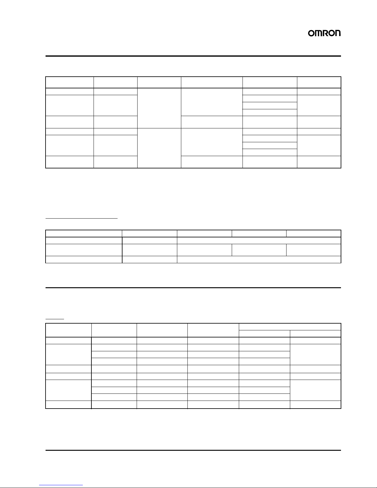
■List of Models
Note: 1. Product is labelled “250 VAC”.
2. Product is labelled “50 VDC”.
3. When ordering, specify the rated input voltage.
■Accessories (Order Separately)
Connecting Sockets
Refer to page 297 for details.
Specifications
■Rati ngs (at an Ambient Temperature of 25°C)
Input
Note: Constant-current input circuit.
Isolation Zero cross
function
Indicator Rated output load Rated input voltage Model
Photocoupler Yes Yes 3 A at 100 to 240 VAC
(See note 1.)
5 to 24 VDC G3H-203SN-VD
Phototriac coupler No 5 VDC G3H-203SLN-VD
12 VDC
24 VDC
Photocoupler No 3 A at 4 to 48 VDC
(See note 2.)
5 to 24 VDC G3HD-X03SN-VD
Photocoupler Yes No 3 A at 100 to 240 VAC
(See note 1.)
4 to 24 VDC G3H-203S-VD
Phototriac coupler No 5 VDC G3H-203SL-VD
12 VDC
24 VDC
Photocoupler No 3 A at 4 to 48 VDC
(See note 2.)
4 to 24 VDC G3HD-X03S-VD
Item PTF08A-E PT08 PT08-0 PT08QN
Connecting Front connecting Bac k connecting
Mounting method/
Terminal type
Track mounted
screw terminals
Solder terminals PCB terminals Wire-wrapping terminals
Hold-down clip PYC-A1 PYC-P
Model Rated voltage Operating voltage Impedance Voltage level
Must operate voltage M us t release voltage
G3H-203SN-VD 5 to 24 VDC 4 to 28 VDC 15 mA max. (See note.) 4 VDC max. 1 VDC min.
G3H-203SLN-VD 5 VDC 4 to 6 VDC 390
Ω±20% 4 VDC max. 1 VDC min.
12 VDC 9.6 to 14.4 VDC 900
Ω±20% 9.6 VDC max.
24 VDC 19.2 to 28.8 VDC 2 k
Ω±20% 19.2 VDC max.
G3HD-X03SN-VD 5 to 24 VDC 4 to 28 VDC
1.5 k
Ω
+20%
/
–10%
4 VDC max. 1 VDC min.
G3H-203S-VD 4 to 24 VDC 3 to 28 VDC 15 mA max. (See note.) 3 VDC max. 1 VDC min.
G3H-203SL-VD 5 VDC 4 to 6 VDC 390
Ω±20% 4 VDC max. 1 VDC min.
12 VDC 9.6 to 14.4 VDC 900
Ω±20% 9.6 VDC max.
24 VDC 19.2 to 28.8 VDC 2 k
Ω±20% 19.2 VDC max.
G3HD-X03S-VD 4 to 24 VDC 3 to 28 VDC
1.5 k
Ω
+20%
/
–10%
3 VDC max. 1 VDC min.
Page 3

226 Solid State Relays G3@-VD G3H/G3HD
Output
■Characteristics
Engineering Data
Load Current vs.
Ambient Temperature
Characteristics
One Cycle Surge
Current: Non-repetitive
Model Applicable load
Rated load voltage L oad voltage range Load current Inrush current
G3H-203SN-VD
G3H-203S-VD
100 to 240 VAC 75 to 264 VAC 0.1 to 3 A 45 A 60 Hz, 1 cycle
G3H-203SLN-VD
G3H-203SL-VD
G3HD-X03SN-VD
G3HD-X03S-VD
4 to 48 VDC 3 to 52.8 VDC 0.1 to 3 A 18 A (10 ms)
Model G3H-203SN-VD/203S-VD G3H-203SLN-VD/203SL-VD G3HD-X03SN-VD/X03S-VD
Operate time 1/2 cycle of load power source +
1ms max.
1 ms max. 0.5 ms max.
Release time 1/2 cycle of load power source + 1 ms max. 2 ms max.
Output ON voltage drop 1.6 V (RMS) max. 1.5 V max.
Leakage current 5 mA max. (at 100 VAC);
10 mA max. (at 200 VAC)
2.5 mA max. (at 100 VAC);
5 mA max. (at 200 VAC)
5 mA max. (at 50 VDC)
Insulation resistance 100 M
Ω min. (at 500 VDC)
Dielectric strength 2,000 VAC, 50/60 Hz for 1 min 1,500 VAC, 50/60 Hz for 1 min
Vibration resistance Destruction: 10 to 55 to 10 Hz, 0.75-mm single amplitude
Shock resistance
Destruction: 1,000 m/s
2
Ambient temperature Operating: –30°C to 80°C (with no icing)
Storage: –30
°C to 100°C (with no icing)
Ambient humidity 45% to 85%
Certified standards G3H: UL508, CSA C22.2 No. 14, EN60947-4-3
G3HD: UL508, CSA C22.2 No. 14, EN60950
Weight Approx. 50 g
Ambient temperature (°C)
Load current (A)
Non-repetitive (Keep the inrush current to half the rated value if it occurs repetitively.)
Inrush current (A, Peak)
Energized time (ms) Energized time (ms)
G3HD-X03SN-VD/X03S-VD
Inrush current (A)
G3H-203SN-VD/203S-VD/203SLN-VD/
203SL-VD
G3HD-X03SN-VD/X03S-VD
G3H-203SN-VD/203S-VD/203SLN-VD/
G3H-203SL-VD
Page 4

In the interest of product improvement, specifications are subject to change without notice.
ALL DIMENSIONS SHOWN ARE IN MILLIMETERS.
To convert millimeters into inches, multiply by 0.03937. To convert grams into ounces, multiply by 0.03527.
Cat. No. K057-E1-05
Solid State Relays G3@-VD G3H/G3HD 227
Dimensions
Note: All units are in millimeters unless otherwise indicated.
Safety Precautions
■Precautions for Correct Use
Please observe the following precautions to prevent failure to
operate, malfunction, or undesirable effect on product performance.
The SSR case serves to dissipate heat. Install the relays so that they
are adequately ventilated. If poor ventilation is unavoidable, reduce
the load current by half.
Connection
With the SSR for DC switching, the load can be connected to either
positive or negative output terminal of the SSR.
Protective Component
Since the SSR does not incorporate an overvoltage absorption
component, be sure to connect an overvoltage absorption
component when using the SSR under an inductive load.
1
3
5
7
2
4(+)
6(−)
8
−
+
−
+
(+)
(−)
( )
Load
Load
Input voltage
2. The coil has no polarity.
28 max.
21.5 max.
36.5 max.
42.5 max.
Terminal Arrangement/
Internal Connections
(Bottom View)
Input
Note: 1. The plus and minus symbols
shown in the parentheses
are for DC loads.
Load power
supply
 Loading...