

Page 1

ZX-T Series
Cat. No. Z306-E1-02A
Vision Sensor
SHORT MANUAL
Cat. No. Z306-E1-02A Vision Sensor FQ SHORT MANUAL
FQ
Page 2

Page 3

Table of Contents
1. Introduction
1-1 FQ-series Vision Sensors. . . . . . . . . . . . . . . . . . . . . . . . . . . . . . . . . . . . . . . 4
1-2 Measurement Process . . . . . . . . . . . . . . . . . . . . . . . . . . . . . . . . . . . . . . . . . 5
1-3 Startup Display and Display Elements . . . . . . . . . . . . . . . . . . . . . . . . . . . . 6
1-4 Basic Operational Flow. . . . . . . . . . . . . . . . . . . . . . . . . . . . . . . . . . . . . . . . . 8
2. Installation and Connections
2-1 System Configuration. . . . . . . . . . . . . . . . . . . . . . . . . . . . . . . . . . . . . . . . . 10
2-2 Installation . . . . . . . . . . . . . . . . . . . . . . . . . . . . . . . . . . . . . . . . . . . . . . . . . . 11
2-3 Wiring . . . . . . . . . . . . . . . . . . . . . . . . . . . . . . . . . . . . . . . . . . . . . . . . . . . . . . 15
2-4 Setting Up Ethernet. . . . . . . . . . . . . . . . . . . . . . . . . . . . . . . . . . . . . . . . . . . 20
3. Taking Images
3-1 Selecting a Sensor for Configuration . . . . . . . . . . . . . . . . . . . . . . . . . . . . 24
3-2 Adjusting Image Quality . . . . . . . . . . . . . . . . . . . . . . . . . . . . . . . . . . . . . . . 25
3-3 Adjusting the Object Position . . . . . . . . . . . . . . . . . . . . . . . . . . . . . . . . . . 30
4. Setting Up Inspections
4-1 Inspection Item Selection Guide . . . . . . . . . . . . . . . . . . . . . . . . . . . . . . . . 34
4-2 Setup Procedure for Inspection Items . . . . . . . . . . . . . . . . . . . . . . . . . . . 35
4-3 Inspecting with the Search Inspection Item . . . . . . . . . . . . . . . . . . . . . . . 36
4-4 Inspecting with the Edge Position Inspection Item . . . . . . . . . . . . . . . . . 38
4-5 Inspecting with the Edge Width Inspection Item . . . . . . . . . . . . . . . . . . . 40
4-6 Inspecting with the Area Inspection Item . . . . . . . . . . . . . . . . . . . . . . . . . 42
4-7 Inspecting with Color Data Inspection Item . . . . . . . . . . . . . . . . . . . . . . . 44
Table of Contents
5. Testing and Saving Settings
5-1 Performing Test Measurements. . . . . . . . . . . . . . . . . . . . . . . . . . . . . . . . . 48
5-2 Adjusting the Judgement Parameters. . . . . . . . . . . . . . . . . . . . . . . . . . . . 49
5-3 Checking a List of All Inspection Item Results . . . . . . . . . . . . . . . . . . . . 51
5-4 Saving Data to the Sensor . . . . . . . . . . . . . . . . . . . . . . . . . . . . . . . . . . . . . 52
FQ Short Manual
1
Page 4

6. Operation
6-1 Starting Operation. . . . . . . . . . . . . . . . . . . . . . . . . . . . . . . . . . . . . . . . . . . . 54
6-2 Configuring the Run Mode Display . . . . . . . . . . . . . . . . . . . . . . . . . . . . . . 56
6-3 Adjusting Judgement Parameters during Operation. . . . . . . . . . . . . . . . 58
7. Communications with External Devices
7-1 Operation with Default Configuration . . . . . . . . . . . . . . . . . . . . . . . . . . . . 60
7-2 Setting the Measurement Trigger . . . . . . . . . . . . . . . . . . . . . . . . . . . . . . . 61
7-3 Setting the Outputs. . . . . . . . . . . . . . . . . . . . . . . . . . . . . . . . . . . . . . . . . . . 65
7-4 Controlling the Sensor from an External Device . . . . . . . . . . . . . . . . . . . 68
Revision History . . . . . . . . . . . . . . . . . . . . . . . . . . . . . . . . . . . . . . . . . . . . . . . . . 74
2
FQ Short Manual
Page 5

Introduction
1-1 FQ-series Vision Sensors . . . . . . . . . . . . . . . . . . . . . . . . . . . . . . . . . . . .4
1-2 Measurement Process . . . . . . . . . . . . . . . . . . . . . . . . . . . . . . . . . . . . . . .5
1-3 Startup Display and Display Elements . . . . . . . . . . . . . . . . . . . . . . . . . .6
1-4 Basic Operational Flow . . . . . . . . . . . . . . . . . . . . . . . . . . . . . . . . . . . . . .8
1
Introduction
Page 6
1-1 FQ-series Vision Sensors
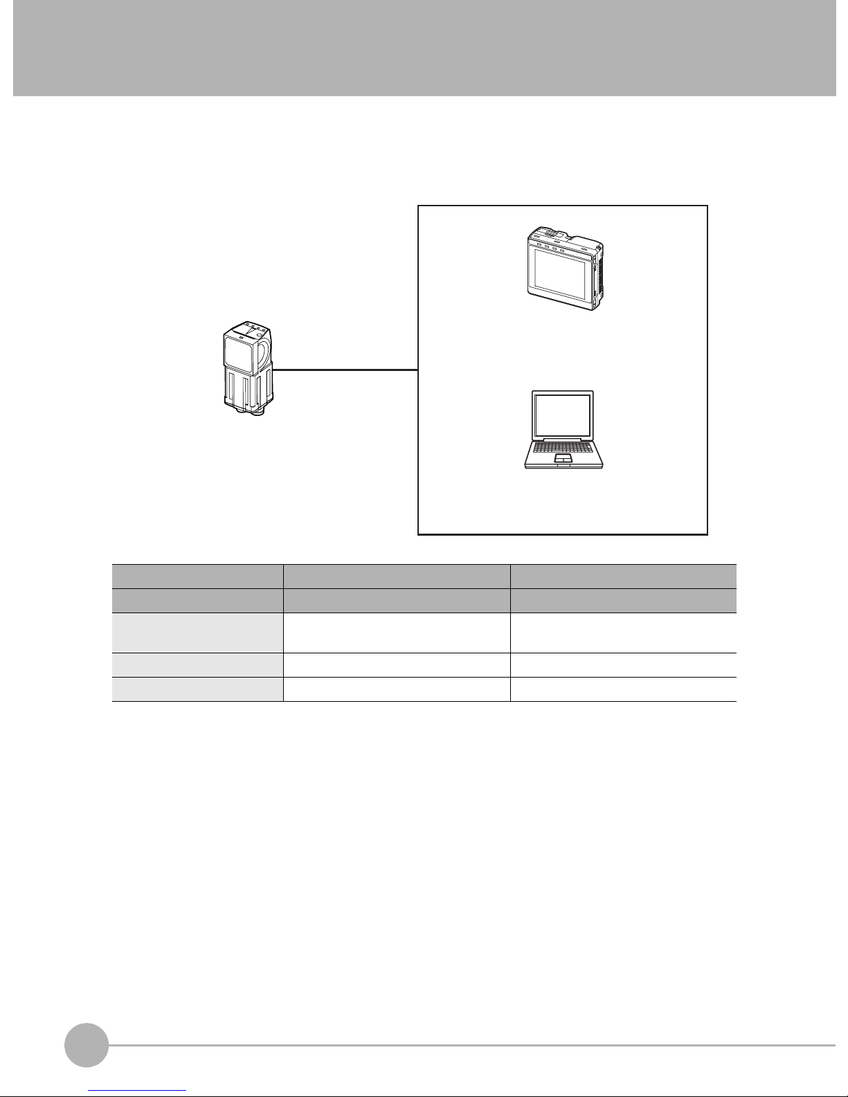
FQ-series Vision Sensors are real-color Vision Sensors with integrated processing. Once configured, they are
used stand-alone for quality inspection of presence, position, and other product characteristics. To set up or
monitor the sensors, either the touch screen based console 'Touch Finder' or a 'PC Tool' can be used.
Setup, Image Confirmation, and Logging Tools
Touch Finder
FQ Vision Sensor
Used to check images and set the judgement
parameters. It can also be used to save
measurement results and check status during
operation.
PC Tool
Includes the camera, lighting, measurement
processor, and I/O functions.
After the Sensor has been set up, it can be
operated alone to perform measurements
without the Touch Finder or PC Tool.
The same functions as those that are provided
by the Touch Finder can be performed from a
computer. The PC Tool is available free of
charge.
FQ-series Vision Sensors are available in two different models. The differences are given in the following table.
Model Standard model Single-function model
Model number FQ-S2@@@@@ FQ-S1@@@@@
Number of simultaneous
measurements
Number of registered scenes 32 8
Position compensation Supported Not supported
32 1
4
FQ-series Vision Sensors
FQ Short Manual
Page 7
1-2 Measurement Process
This section describes the basic flow of the measurement process.
• The measurement is started by inputting a trigger signal from an external
Trigger input
Take image
Measurement
Overall judgement
output
device.
• Images are taken according to the trigger.
• The image is measured to see if it matches the configured settings.
• The overall judgement of all inspection items are output using OR logic.
1
Introduction
Logging
• Measurement data and image data can be logged in memory in the Sensor or
in an SD card.
FQ Short Manual
Measurement Process
5
Page 8
1-3 Startup Display and Display Elements
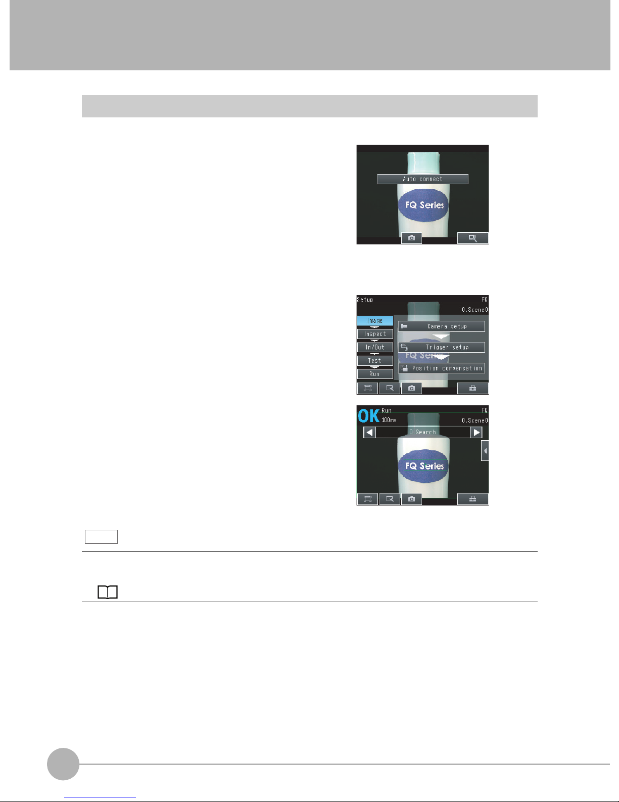
Startup Display
1 The Sensor is automatically detected by the Touch
Finder when power supply to the Sensor and Touch
Finder is turned ON.
The Auto Connect Display will appear if the Sensor cannot be detected. Check that cables are connected correctly to the Sensor and Touch Finder, and then press
[Auto connect].
2 When the Sensor is detected, the following display will appear.
• The Setup Mode will appear if a Sensor that has not been
set up is connected.
• The Run Mode will appear if a Sensor that has been set
up is connected.
Note
When the Touch Finder is started, IP addresses are automatically set for each Sensor.
To allocate specific IP addresses, set the IP address of each Sensor and the Touch Finder.
Setting Up Ethernet: p. 20
6
Startup Display and Display Elements
FQ Short Manual
Page 9
Display Elements
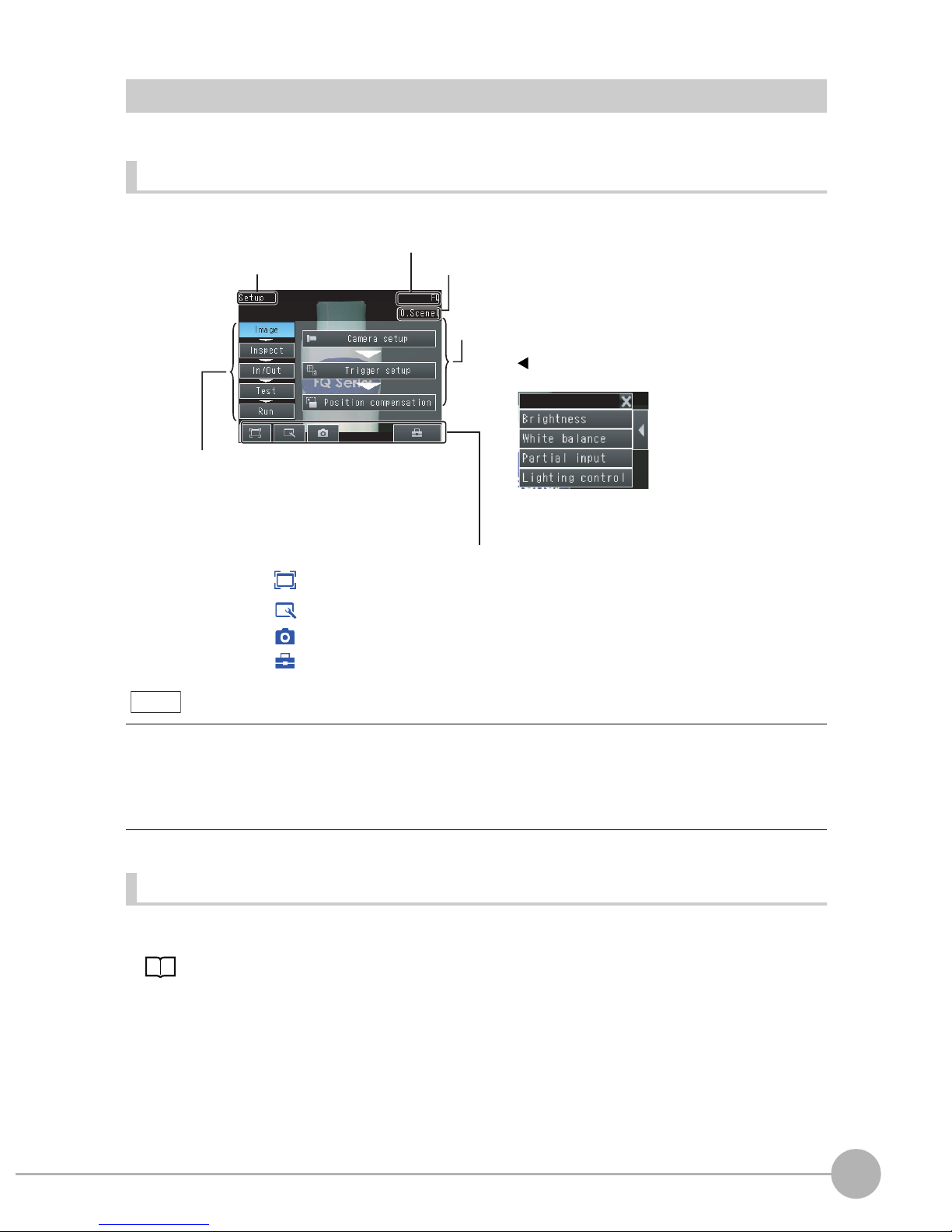
This Sensor has a Setup Mode and a Run Mode.
Setup Mode
In Setup Mode, you can set the image conditions, judgement parameters, and I/O settings for the Sensor.
The name of the mode or the
menu hierarchy is displayed.
The setup flow is shown by these five tabs.
[Image]: Used to adjust the image.
[Inspect]: Used to set the inspection items.
[In/Out]: Used to set the I/O.
[Test]: Used to test and adjust the set measurements.
[Run]: Used to switch to Run Mode.
Only-image Button: Used to select either displaying the camera image and messages, or
Display Button: Used to select the source of the image or to zoom the image.
Capture Button: Used to capture the current screen to the SD card.
Tool Button: Used to call functions, such as saving data or select scenes.
The name of the Sensor being set up is displayed.
The selected scene number is displayed.
The menu changes according to the selected tab page.
• Buttons will appear on the right according to the mode.
• If the [ ] Button appears, pressing it will display the
sub-menu or commands.
This button menu is always displayed.
only the camera image.
1
Introduction
Note
The Display Button can be used to switch between the following images.
• Live: The live image is displayed.
• Freeze: The image that was taken last is displayed.
• Log: An image saved in internal memory is displayed.
• File: An image saved on an SD card is displayed.
Run Mode
In Run Mode, measurements are performed, and measurement results are output.
p. 53
FQ Short Manual
Startup Display and Display Elements
7
Page 10
1-4 Basic Operational Flow
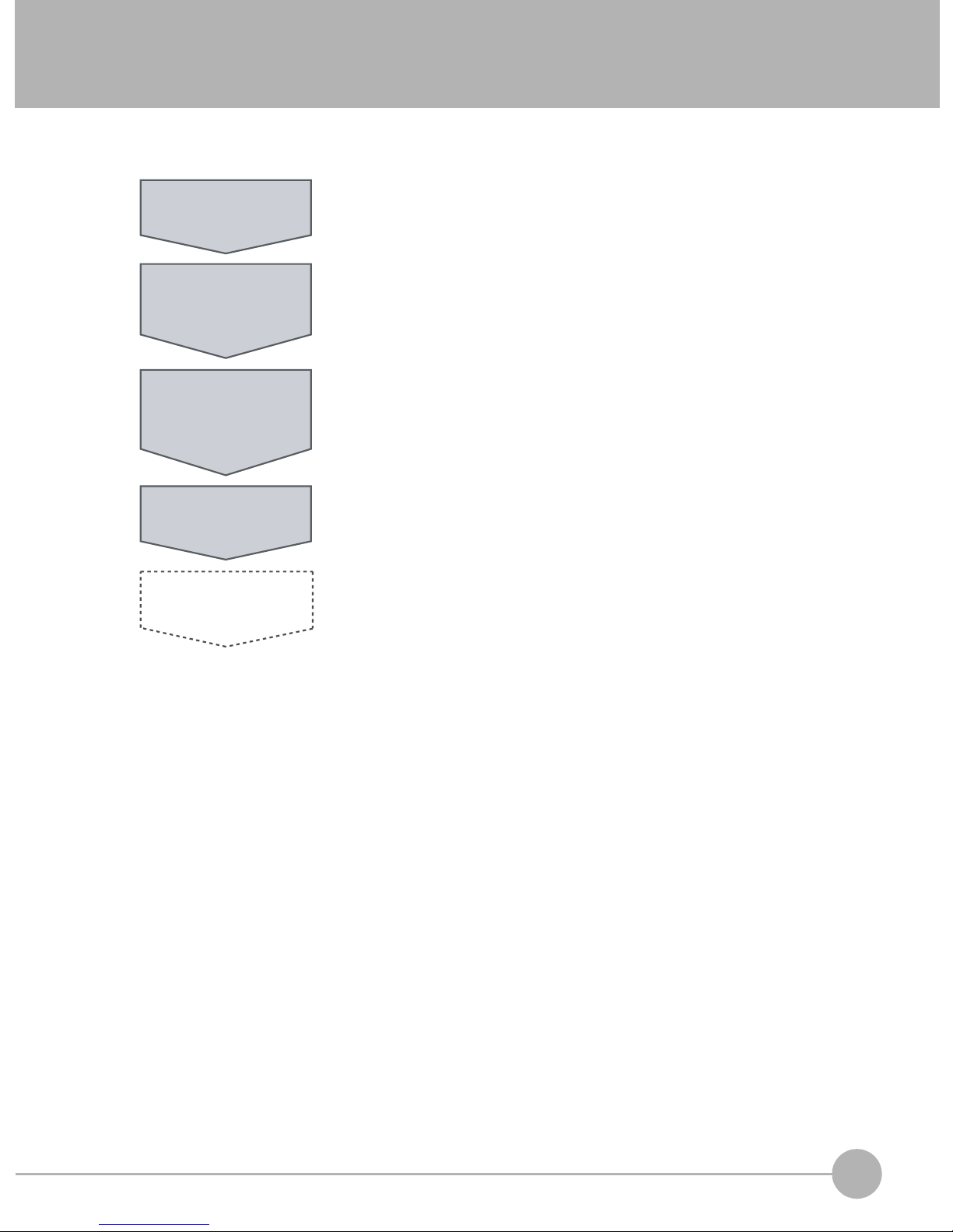
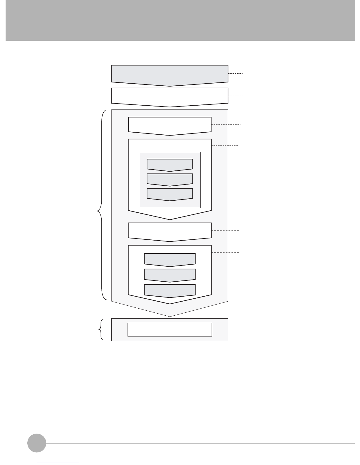
The following flow shows the basic operation of FQ-series Vision Sensors.
Setup Evaluation
Connections and Wiring
Starting the Sensor
Section 2 Installation
and Connections
Section 1
1-3 Startup Display
and Display Elements
Image Setup
([Image] Tab Page)
Inspection Setup
([Inspect] Tab Page)
Registering
Inspection Items
Teaching
Setting Judgement
Parameters
*1
Output Settings
([In/Out] Tab Page)
Section 3 Taking
Images
Section 4 Setting Up
Inspections
Section 7
Communications with
External Devices
Testing ([Test] Tab Page)
Test Measurement and
Results Verification
Section 5 Testing and
Saving Settings
Adjusting Judgement
Parameters
Saving the Settings
Operation
*2
Starting Operation (Run Mode)
Section 6 Operation
*1: In Setup Mode, the Sensor can be set up and adjusted, but it does not output signals on the I/O lines.
*2: In Run Mode, the Sensor performs measurements and outputs signals on the I/O lines.
8
Basic Operational Flow
FQ Short Manual
Page 11

Installation and Connections
2-1 System Configuration . . . . . . . . . . . . . . . . . . . . . . . . . . . . . . . . . . . . . .10
2-2 Installation . . . . . . . . . . . . . . . . . . . . . . . . . . . . . . . . . . . . . . . . . . . . . . . 11
2-3 Wiring . . . . . . . . . . . . . . . . . . . . . . . . . . . . . . . . . . . . . . . . . . . . . . . . . . . 15
2-4 Setting Up Ethernet . . . . . . . . . . . . . . . . . . . . . . . . . . . . . . . . . . . . . . . . 20
2
Installation and Connections
Page 12
System Configuration
10
FQ Short Manual
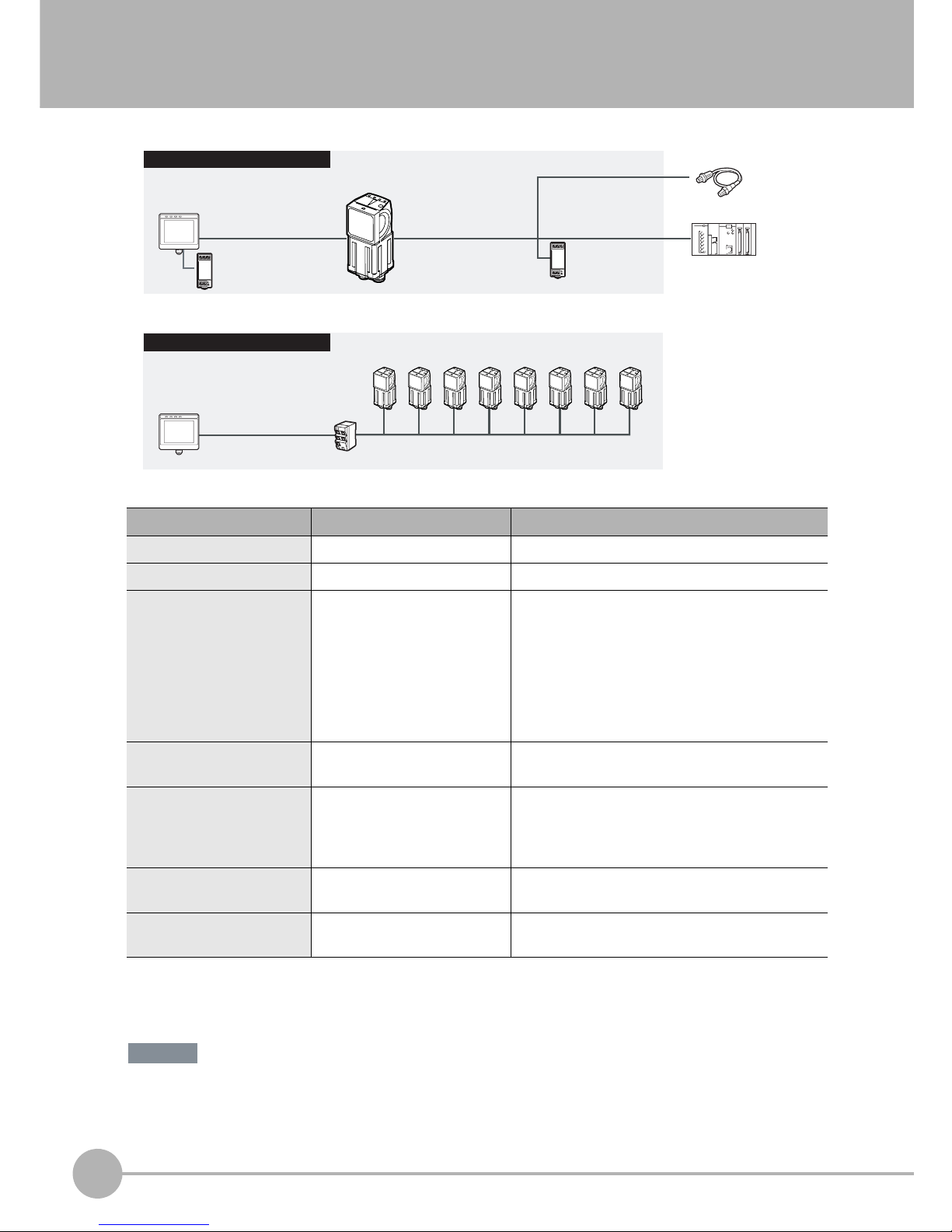
2-1 System Configuration
*1: The shape and dimensions of the Ethernet connector plug and jack are specified in ISO/IEC8877:1992 (JIS X 5110:1996) and RJ-45 of the
FCC regulations.
To prevent connector connection failures, the structure of the jack of this product does not allow insertion of plugs that do not comply with the
standard.
If a commercially available plug cannot be inserted, it is likely that the plug is non-compliant.
Do not connect network devices other than PLCs on the same network as the Touch Finder or computer. If
another device is connected, the responsiveness of displays and settings of the Touch Finder or computer may
become slow.
Product Model number Remarks
FQ Vision Sensor FQ-S@@@@@@ This is the Vision Sensor.
Touch Finder FQ-D@@ This is a setup console.
PC Tool --- The PC Tool can be used instead of the Touch
Finder. If you register as a member, you can download the free PC Tool as a special service to purchasers.
Refer to the Member Registration Sheet that is
enclosed with the Sensor for the member registration procedure and the download procedure for special member software.
FQ Ethernet Cable FQ-WN0@@ Connects the Sensor to the Touch Finder or com-
puter.
Standard RJ45 Ethernet
Cable
*1
--- Connects the switching hub to the Touch Finder or
computer. Use a connector that complies with the
FCC RJ45 standard. (STP (shielded twisted-pair)
cable, category 5e or 6, impedance: 100 Ω)
I/O Cable FQ-WD0@@ Connects the Sensor to the power supply and exter-
nal devices.
Switching Hub W4S1-0@@ Used to connect multiple Sensors to one Touch
Finder or PC Tool.
PLC
Switching Hub
Standard RJ45 Ethernet
Cable
FQ Ethernet Cable
Connect the trigger
sensor, PLC, and
power supply to
each Sensor.
Touch Finder or PC Tool
Setup Tool
FQ Vision Sensors
(8 max.)
24-VDC power supply
24-VDC power
supply
FQ Ethernet Cable I/O Cable
Touch Finder or PC Tool
Setup Tool
FQ Vision Sensor
Standard Configuration
Multiple Connection Sensors
Trigger Sensor
Important
Page 13
2-2 Installation
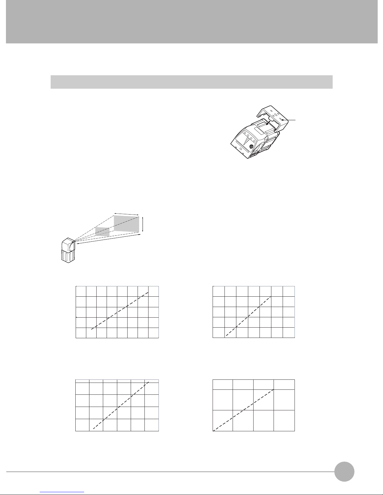
Installing the Sensor
Installation Procedure
1 Align the tabs on one side of the Mounting Bracket with
the slot on the Sensor.
The FQ-XL Mounting Bracket can be attached to the back,
side, or front of the Sensor.
2 Press the Mounting Bracket onto the Sensor until the oth-
er tabs click into place.
3 Use the following optical charts to check the field of view
and installation distance of the Sensor so that it is mounted at the correct position.
Tightening torque (M4): 1.2 N·m
Horizontal field of view
Vertical field
of view
Installation distance (L)
The optical chart indicates the horizontal
field of view. The vertical field of view will
be approximately 60% of the horizontal
field of view.
Note: The tolerance is ±10%.
Mounting
Bracket
2
Installation and Connections
FQ-S10010F, FQ-15010F,
FQ-S20010F, or FQ-25010F
Installation distance (L) (mm)
55
45
35
6
FQ-S10050F, FQ-S15050F,
FQ-S20050F, or FQ-S25050F
Installation distance (L) (mm)
210
130
50
0 20 40 60
8 10 12 14
Horizontal field of view (mm)
Horizontal field of view (mm)
FQ-S10100F, FQ-S15100F,
FQ-S20100F, or FQ-S25100F
Installation distance (L) (mm)
1,000
600
200
0100200 300
Horizontal field of view (mm)
FQ-S10100N, FQ-S15100N,
FQ-S20100N, or FQ-S25100N
Installation distance (L) (mm)
400
0
0
200 400
Horizontal field of view (mm)
FQ Short Manual
Installation
11
Page 14
Important
• There is a certain amount of deviation among Sensors in the center of the optical axis. For this reason, when install-
ing the Sensor, check the center of the image and the field of view on the LCD monitor of the Touch Finder and in
the PC Tool.
Removal Procedure
1 Insert a flat-blade screwdriver between the Mounting Brack-
et and the Sensor case on either side and remove the
Mounting Bracket.
Mounting
Bracket
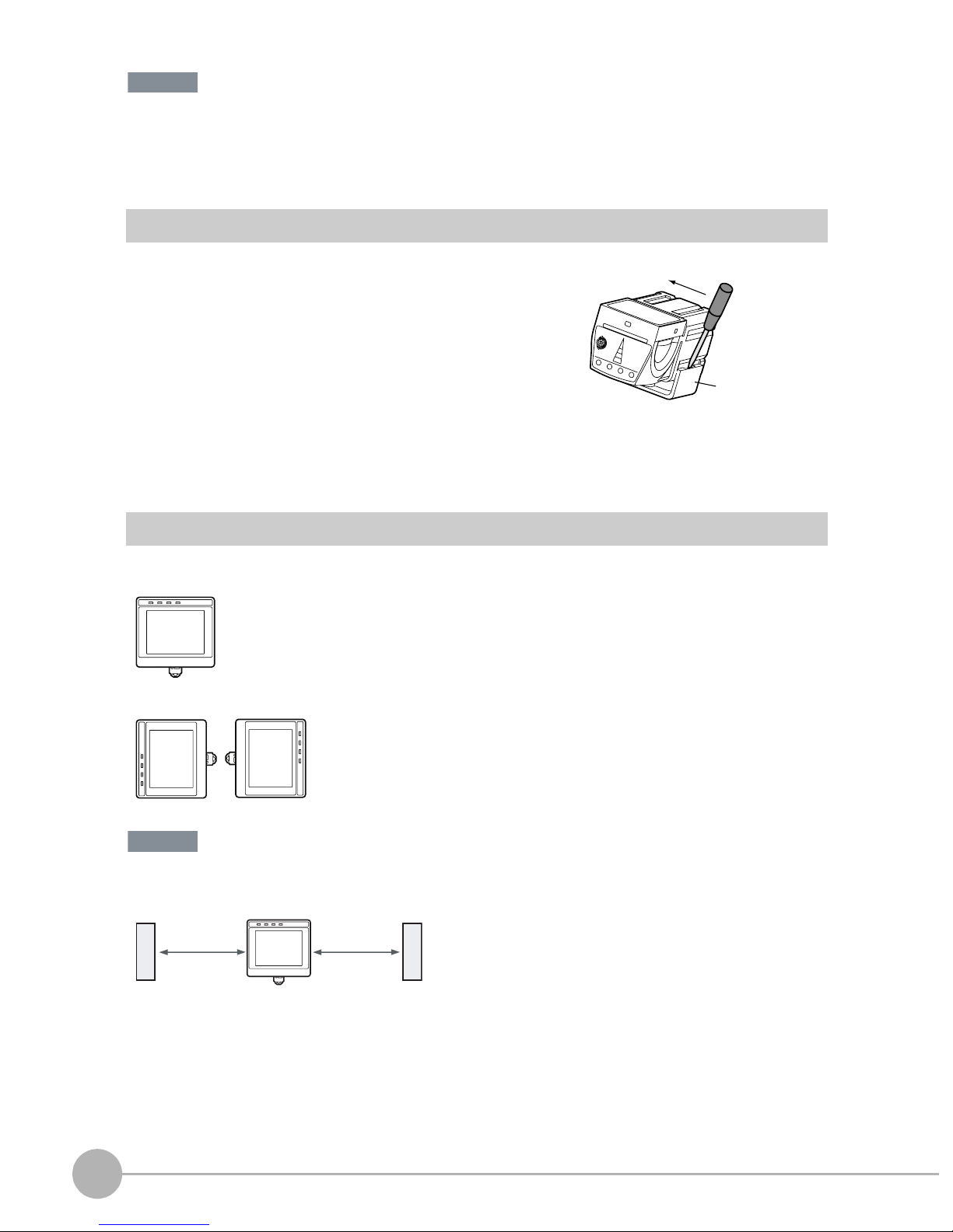
Installing the Touch Finder
Installation Precautions
Install the Touch Finder in the following orientation to allow sufficient heat dissipation.
Do not mount it in the following orientations.
Important
• To improve ventilation, leave space on both sides of the Touch Finder. The distance between the Touch Finder and
other devices should be at least that shown in the following diagram.
15 mm min.
• Make sure that the ambient temperature is 50°C or lower. If it exceeds 50°C, install an cooling fan or an air condi-
tioner and maintain the temperature at 50°C or lower.
• To prevent interference by noise, do not mount the Sensor on panels which contain high-voltage devices.
• To keep the level of noise from the surrounding environment to a minimum, install the Sensor and Touch Finder at
least 10 m away from power lines.
15 mm min.
12
Installation
FQ Short Manual
Page 15
Mounting to DIN Track
Installation Procedure
1 Press the slider on the Touch Finder to the top.
2 Hook the clip at the top of the Touch Finder on to the DIN
Track.
3 Press the Touch Finder onto the DIN Track until the bottom
clip clicks into place.
3
Important
• Attach End Plates (sold separately) on the sides of the Touch Finder on the DIN Track.
• If other devices will be installed next to the Touch Finder on the same DIN Track, make sure that sufficient space is
kept between the devices as indicated on previous page.
• Always hook the clip at the top of the Touch Finder on the DIN Track first. If the lower clip is hooked on first, the
Touch Finder will not be mounted very securely.
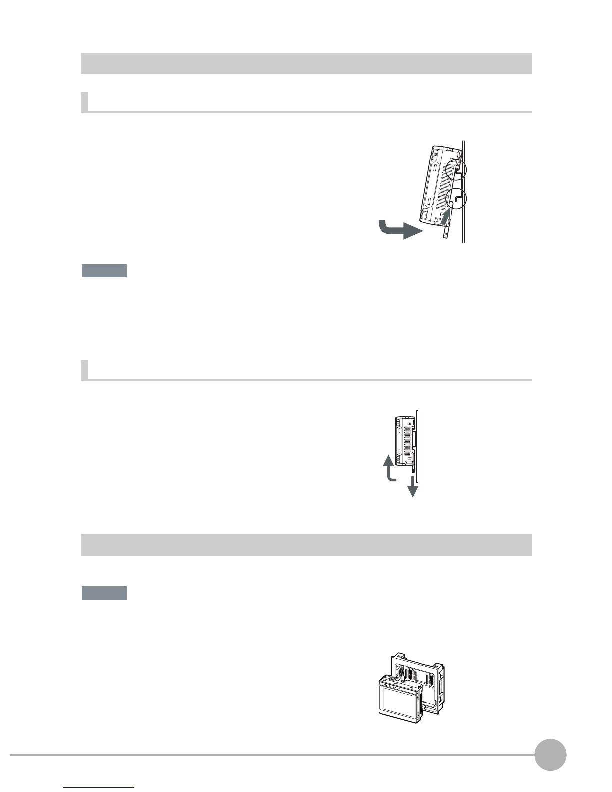
Removal Procedure
2
3
1
1 Pull down on the slider on the Touch Finder.
2 Lift the Touch Finder at the bottom and remove it from the
DIN Track.
2
Installation and Connections
2
1
Mounting to a Control Panel
The Touch Finder can be mounted on a panel using the FQ-XPM Panel Mounting Adapter.
Important
• Always turn OFF the Touch Finder power before attaching or detaching the Panel Mount Adapter. Attaching or
detaching with the power turned ON may cause a failure.
1 Set the Touch Finder in the Panel Mount Adapter.
FQ Short Manual
Installation
13
Page 16
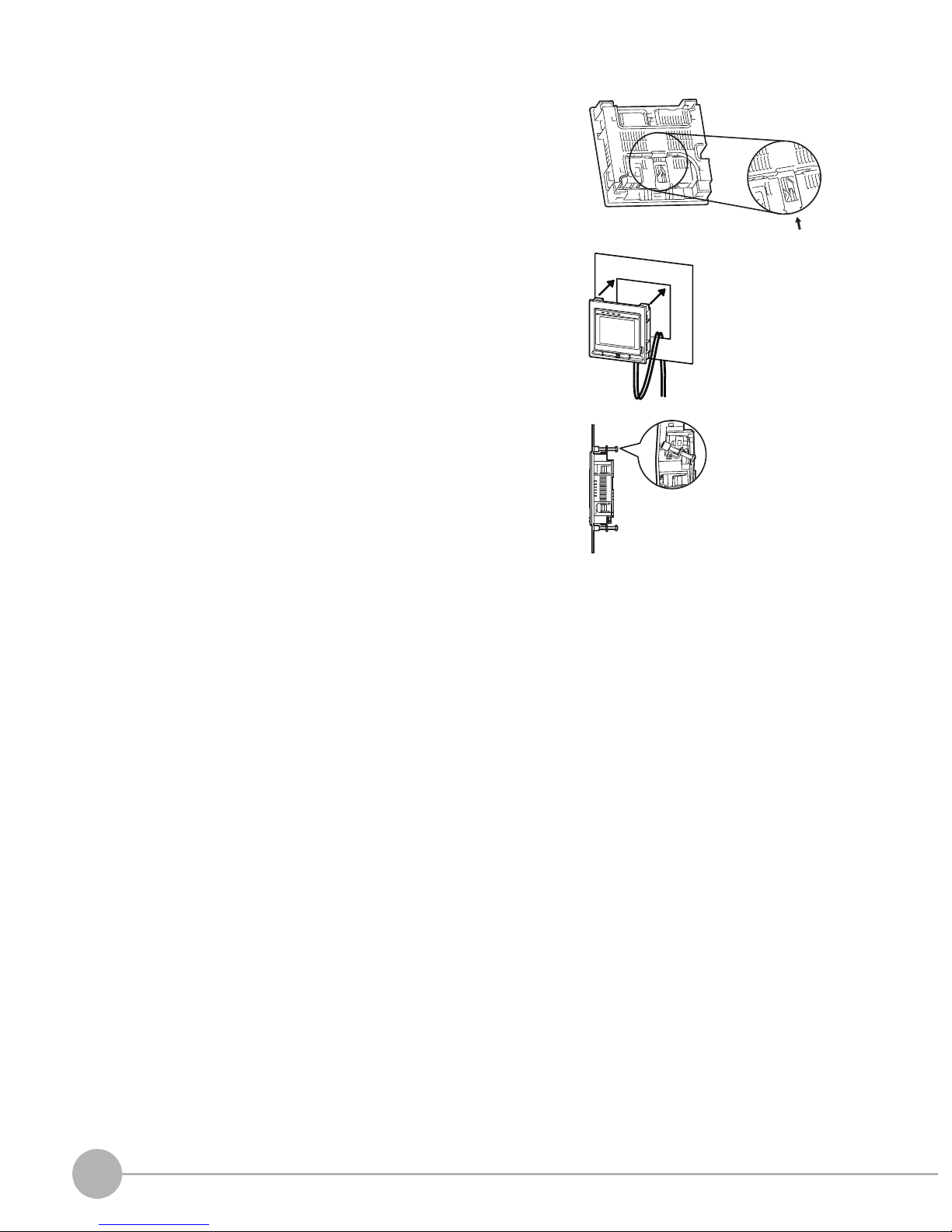
2 Press the slider up on the Touch Finder.
3 Create holes in the panel for mounting.
4 Connect the cable to the Touch Finder.
5 Mount the Touch Finder with the Panel Mount Adapter from
the front of the panel.
6 Hook the hooks on the Mounting Bracket in the four holes
of the Panel Mount Adapter and secure them with screws.
(Tightening torque: 1.2 N·m)
7 Check that the Touch Finder is attached properly to the
Panel.
Mounting
Bracket
14
Installation
FQ Short Manual
Page 17
2-3 Wiring
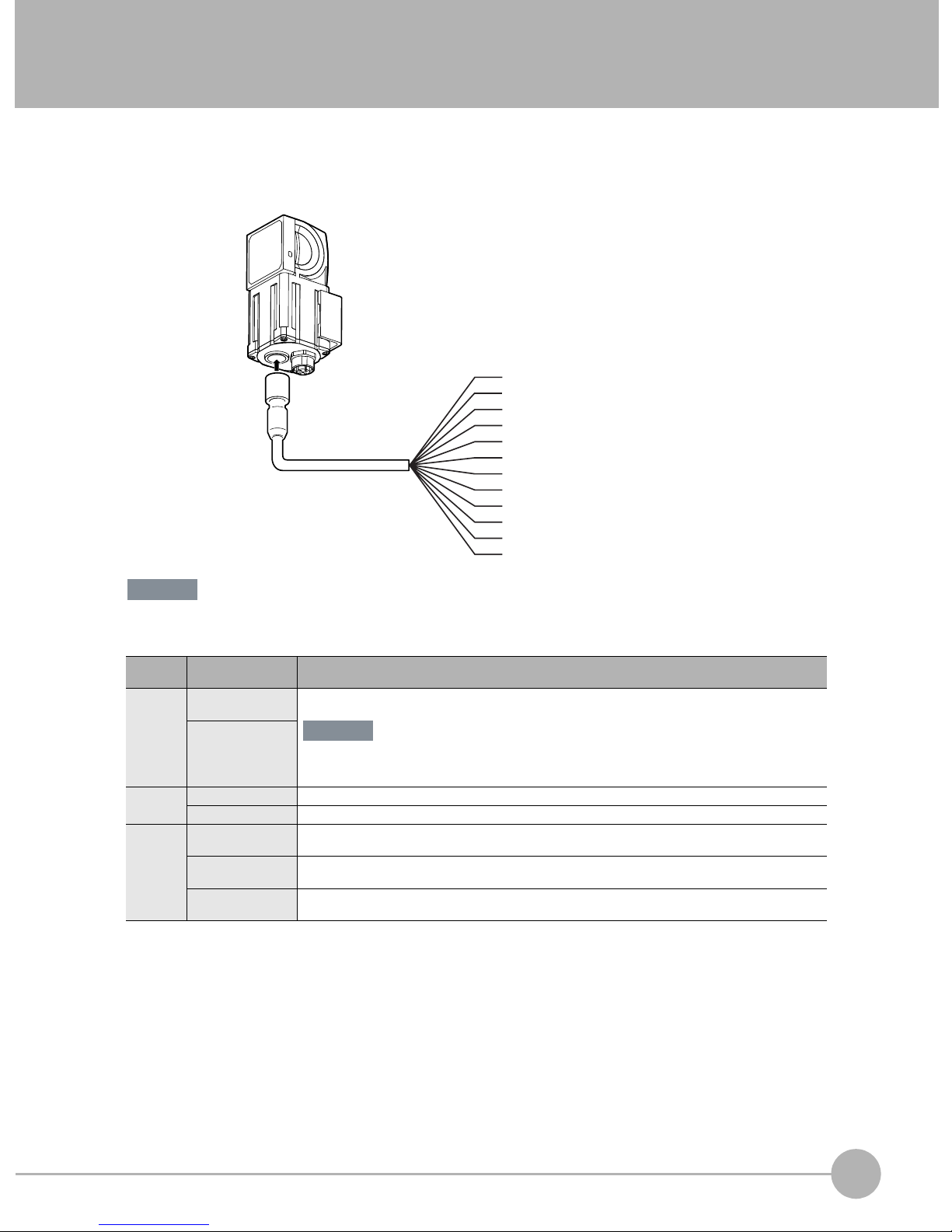
Wiring the Sensor
Connect the I/O Cable to the I/O Cable connector located at the bottom of the Sensor.
2
Installation and Connections
Important
FQ-WD0@@
I/O Cable
Brown
Blue
Black
Orange
Light blue
Pink
Gray
Green
Red
White
Purple
Yellow
Power supply
GND
OUT0 (OR)
OUT1 (BUSY)
OUT2 (ERROR)
TRIG
IN0
IN1
IN2
IN3
IN4
IN5
Cut off lines that are not required so that they do not come into contact the other signal lines.
Classification
Power
supply
Inputs TRIG This terminal is the trigger signal input.
Outputs OUT0 (OR) By default, this is the OR output signal (overall judgement).
Signal Application
Power supply
(24 V)
GND
IN0 to IN5 These are the command input terminals.
OUT1 (BUSY) By default, this is the BUSY output signal.
OUT2 (ERROR) By default, this is the ERROR output signal.
These terminals are for the external power supply (24 V).
Important
Wire the power supply separately from other devices. If the wiring for other devices is placed
together or in the same duct as the wiring for the Vision Sensor, the influences of electromagnetic
induction may cause the Sensor to malfunction or may damage it.
The assignment can be changed to an individual judgement signal from OR0 to OR31.
The assignment can be changed to an individual judgement signal from OR0 to OR31.
The assignment can be changed to an individual judgement signal from OR0 to OR31.
FQ Short Manual
Wiring
15
Page 18
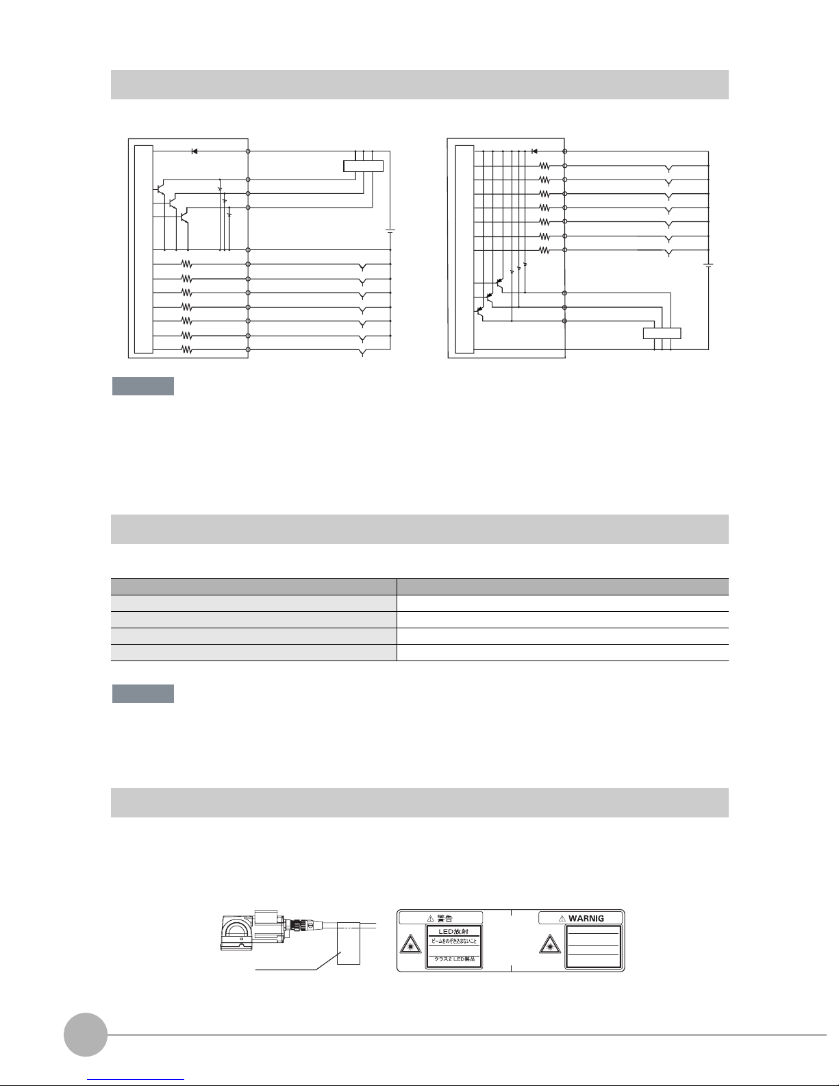
I/O Signal Circuit Diagrams
PNPNPN
Internal circuits
Power supply (24 VDC)
Brown
Black
OUT0 (OR)
Load
OUT1 (BUSY)
Light blue
OUT2 (ERROR)
24 VDC
Blue Yellow
GND (0V)
Pink
TRIG
IN0
Gray
Green
Red
White
Purple
Yellow
IN1
IN2
IN3
IN4
IN5
Internal circuits
Power supply (24 VDC)
Brown
Pink
TRIG
IN0
Gray
GreenOrange
IN1
Red
IN2
IN3
White
Purple
IN4
IN5
Light blue
Orange
Black
Blue
OUT2 (ERROR)
OUT1 (BUSY)
OUT0 (OR)
GND (0V)
24 VDC
Load
Important
Preventing Chattering
• The Sensor is equipped with an anti-chattering function, but if the chattering is 100 µs or longer, a faulty input may
occur. (Input signals of 99 µs or shorter are ignored. Signals of 100 µs or longer are treated as input signals.)
• Use no-contact output devices (e.g., SSR or PLC transistor output) for the input signals. If contacts (e.g., relay) are
used, chattering may cause the trigger to be input again during execution of a measurement.
Power Supply Specifications When a Switching Regulator Is Connected
Use a power supply that meets the following specifications. (The power supply is sold separately.)
Item Description
Power supply voltage 24 VDC (21.6 to 26.4 V)
Output current 3.75 A min.
Recommended Power Supply S8VS-09024@ (24 VDC, 3.75 A)
External power supply terminal screws M4 (tightening torque: 1.2 N·m)
Important
Supply power from a DC power supply for which measures have been applied to prevent high voltages (e.g., a safety
extra low voltage circuit).
If UL certification is required for the overall system, use a UL Class II DC power supply.
Attaching the LED Warning Label
Attach the enclosed LED warning label to the cable or other location. The LED warning label must be attached
to a location that is readily visible from the Sensor.
Attachment Example
Warning Label
Warning Label
Max.60mW 400msec
400-700nm
JIS C 6802:2005
LED RADIATION
DO NOT STARE
INTO BEAM
Max.60mW 400msec
400-700nm
CLASS 2 LED PRODUCT
IEC 60825-1:1993 +A1:1997
+A2:2001
16
Wiring
FQ Short Manual
Page 19
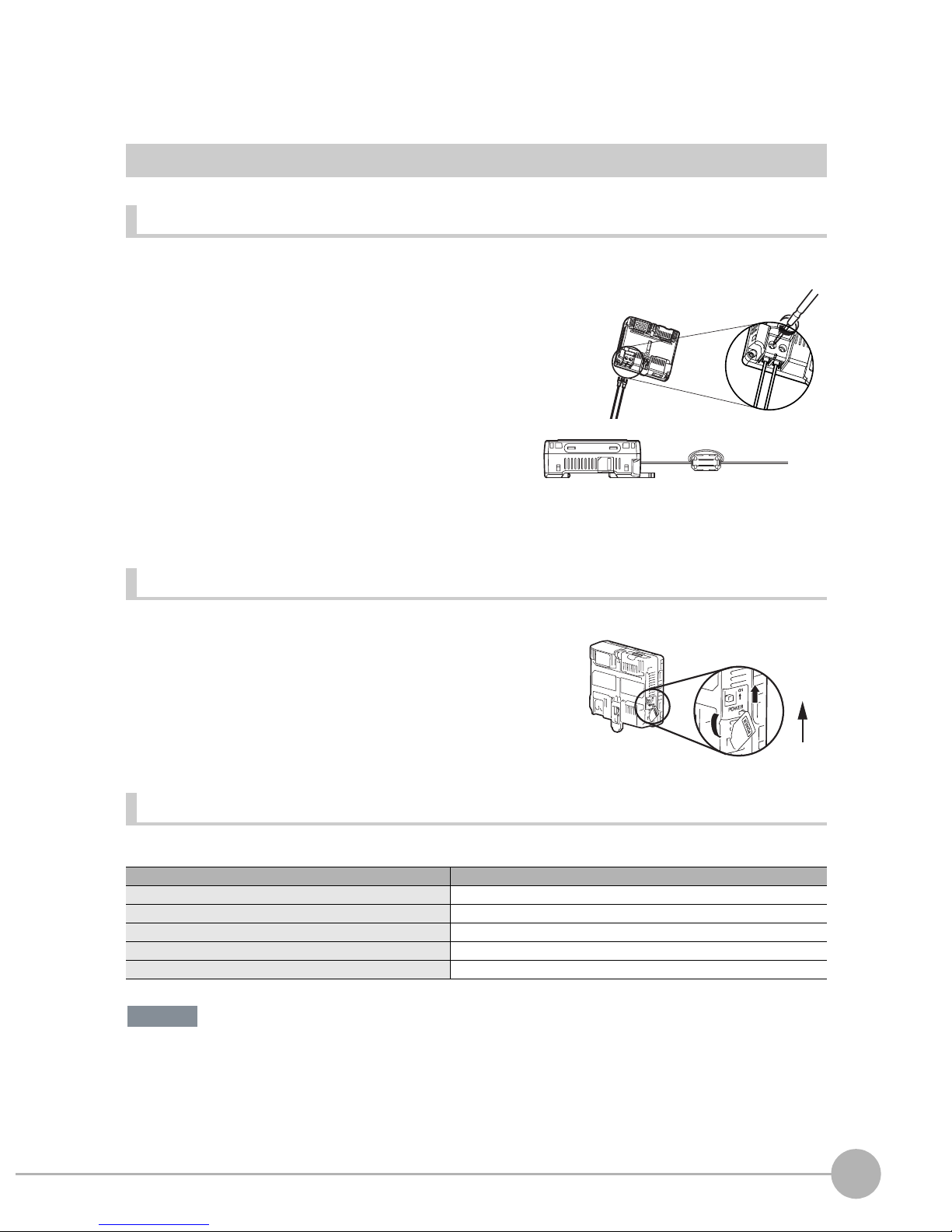
Wiring the Touch Finder
Power Supply Wiring
Connecting the Power Supply
1 Loosen the two terminal screws using a Phillips
screwdriver.
2 Attach crimp terminals to the power lines.
Secure the positive and negative lines as indicated
using M3 screws.
Power supply tightening torque: 0.54 N⋅m
24 VDC
3 In environments where there is excessive noise, at-
tach a ferrite core (ZCAT1730-0730 from TDK or the
equivalent) to the power supply cable.
Turning ON the Touch Finder
1 Remove the cover from the power switch on the left side of
the Touch Finder.
2 Press the switch toward ON.
+
−
When you attach the ferrite core to
the power supply cable, wrap the
cable only one time.
2
1
2
Installation and Connections
ON
OFF
Power Supply Specifications
Use a power supply that meets the following specifications. (The power supply is sold separately.)
Item Description
Power supply voltage 24 VDC (21.6 to 26.4 V)
Output current 2.5 A min.
Recommended Power Supply S8VS-06024@ (24 VDC, 2.5 A)
External power supply terminal screws M4 (tightening torque: 1.2 N⋅m)
Recommended power line wire size AWG16 to AWG22 (length of 5 m max.)
Important
• Supply power from a DC power supply for which measures have been applied to prevent high voltages (e.g., a
safety extra low voltage circuit).
If UL certification is required for the overall system, use a UL Class II DC power supply.
• When using the FQ-D31, do not connect a switching regulator and AC Adapter (FQ-AC@) at the same time.
FQ Short Manual
Wiring
17
Page 20
Charging the Battery
This section describes how to charge and install the FQ-D31 Battery and provides applicable precautions.
Charge the Battery while it is attached to the Touch Finder.
Use the AC adapter to charge the battery.
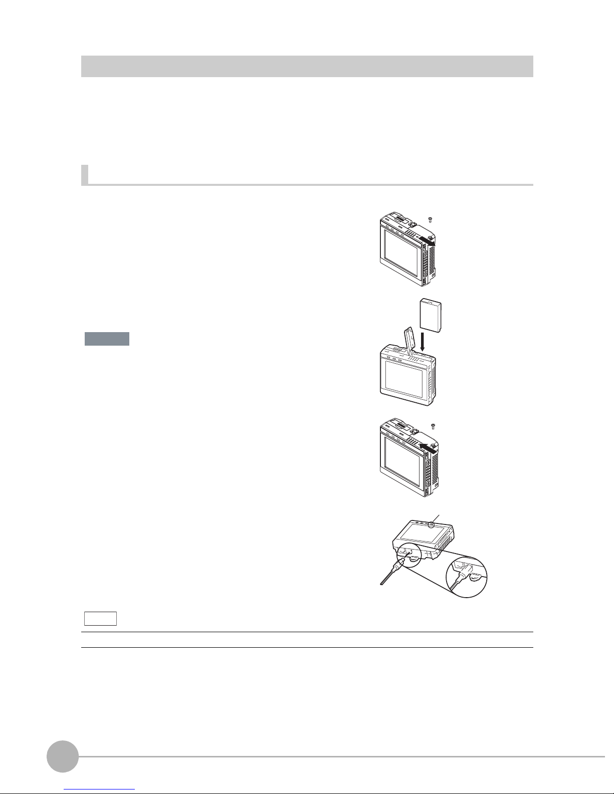
Mounting the Battery in the Touch Finder
1 Remove the screw from the battery cover on the top of the
Touch Finder, slide the cover in the direction of the arrow,
and open the battery cover.
2 Face the rounded side of the battery toward the back of the
Touch Finder and insert the battery.
Important
Do not insert the battery in the wrong orientation.
3 Close the battery cover, slide the battery cover in the direc-
tion of the arrow, and tighten the screw on the battery cover.
4 Attach the AC adapter to the Touch Finder to start changing
the battery.
The CHARGE indicator will be lit while the battery is being
charged. It will go out when charging the battery has been completed.
Note
The Touch Finder will operate even if the AC adapter is connected when no battery is mounted in the Touch Finder.
CHARGE indicator
18
Wiring
FQ Short Manual
Page 21
Important
• If the Touch Finder (FQ-D31) will be installed permanently or semi-permanently, remove the Battery (FQ-BAT1). If
the rated temperature is exceeded with the Battery inserted, the protective circuit may activate and stop the Touch
Finder.
• The battery complies with the following recycling regulation.
Japan Taiwan
EU
Li-ion00
• California regulations concerning perchlorate:
This product is a lithium battery that contains perchlorate, which is regulated by the State of California. Please com-
ply with these regulations. For details see the following URL:
www.dtsc.ca.gov/hazardouswaste/perchlorate/
2
Installation and Connections
FQ Short Manual
Wiring
19
Page 22
2-4 Setting Up Ethernet
Connecting to Sensors from the Touch Finder
When the Sensor is used with a Touch Finder, IP addresses are automatically assigned. No settings are
required to use Ethernet.
However, if a Sensor or Touch Finder is connected to a network where a PLC or computer is already
connected, the Ethernet must be set to be compatible with the existing network.
• Touch Finder
(Setup Mode) − [TF settings] − [Ethernet]
1 Set the IP address and subnet mask according to the network settings.
Connecting to Sensors from a Computer Using the PC Tool
When connecting the Sensor directly to a computer using an Ethernet Cable, set the network settings on the
computer as given below. Setting a fixed IP address is not required if there is a hub between the computer and
Sensor and a DHCP server is used.
The following procedure is for Windows XP.
1 Select [Control Panel] from the Windows Start Menu.
2 Click [Network and Internet Connections] in the control
panel and then double-click [Network Connections].
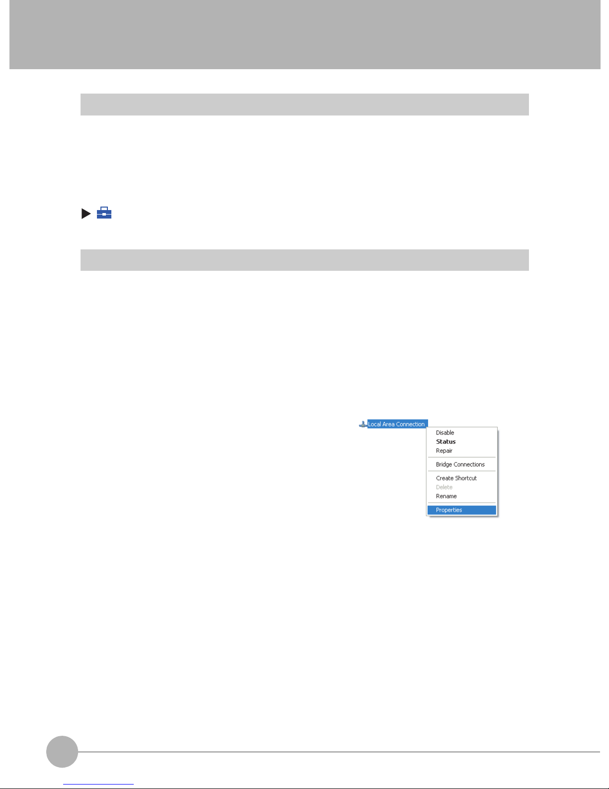
3 Right-click the [Local Area Connection] Icon and select
[Properties].
20
Setting Up Ethernet
FQ Short Manual
Page 23
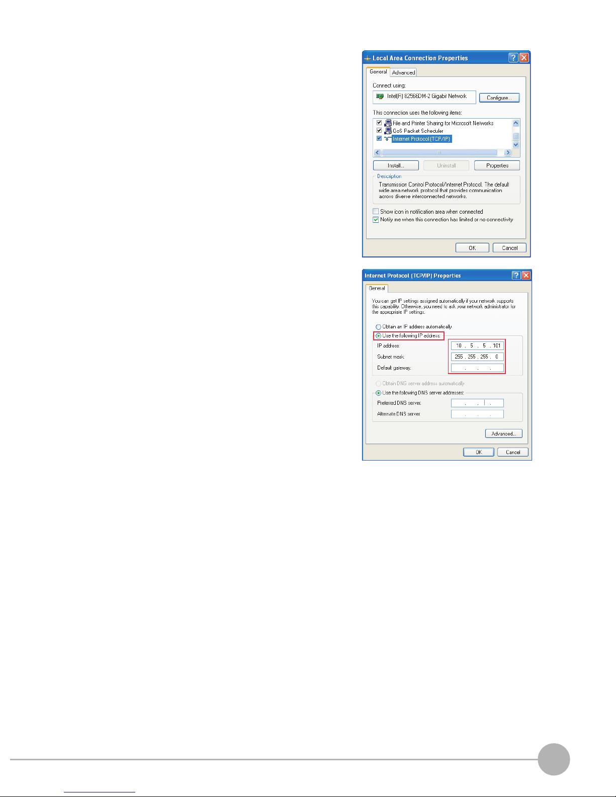
4 On the [General] Tab Page, double-click Internet Proto-
col (TCP/IC).
5 Select the Use the following IP address Option and en-
ter the following IP address and subnet mask.
• IP address: 10.5.5.101
• Subnet mask: 255.255.255.0
6 Click the [OK] Button. This completes the settings.
2
Installation and Connections
FQ Short Manual
Setting Up Ethernet
21
Page 24

MEMO
22
Setting Up Ethernet
FQ Short Manual
Page 25

Taking Images
3-1 Selecting a Sensor for Configuration. . . . . . . . . . . . . . . . . . . . . . . . . . 24
3-2 Adjusting Image Quality . . . . . . . . . . . . . . . . . . . . . . . . . . . . . . . . . . . . 25
3-3 Adjusting the Object Position . . . . . . . . . . . . . . . . . . . . . . . . . . . . . . . . 30
3
Taking Images
Page 26

3-1 Selecting a Sensor for Configuration
If multiple Sensors are connected to a single Touch Finder or computer, you can select the Sensor that you
want to set up.
1 Press [Run].
This will enable setting the current Sensor into RUN
Mode before selecting another Sensor.
2 Then press [Switch to Run mode].
3 Press [Yes].
4 Press − [Switch Sensor].
5 Press the image of the Sensor to be set up.
will be displayed for Sensors that are not yet set.
Note
Once the Touch Finder detects and records a Sensor, the display order for showing more than one Sensor is fixed. Even if the system
configuration is changed to reduce the number of Sensors, the previous display location will remain for Sensors that were removed.
To update displays of multiple Sensors to the current connection sta-
tus, press [ ] - [Auto connect] on the right of the display in step 5,
above, to automatically reconnect.
6 Press − [Sensor settings] to return to Setup
Mode.
7 Press [Yes].
24
Selecting a Sensor for Configuration
FQ Short Manual
Page 27

3-2 Adjusting Image Quality
Adjusting the Focus
[Image] − [Camera setup]
1 Display the Camera Setup Display.
The focus can be seen as a numerical value. The higher
the value, the better the focus.
3
2 Manually adjust the focus using the focus adjust-
ment screw on the Sensor while checking the image
and focus value on the Touch Finder.
In the default settings, the field of view is set to the narrowest setting.
3 Press [Back].
Focus Level
Focus adjustment screw
Turn clockwise to focus on closer objects.
(The field of view will
narrow.)
Turn the screw counterclockwise
to focus on objects at a distance.
(The field of view will widen.)
Taking Images
Important
• Turn the focus adjustment screw clockwise or counterclockwise a little bit to make sure that it has not already
reached the dead stop. Do not force the screw if it does not rotate anymore. This will damage the Sensor.
• Do not turn the focus adjustment knob with a force that is greater than 0.1 N·m. This may damage it.
FQ Short Manual
Adjusting Image Quality
25
Page 28

Adjusting the Brightness
To achieve stable measurements, the brightness of the camera image must be adjusted so that the
characteristic to be measured is clearly visible.
Dark
Brightness of image
Bright
0
100
[Image] − [Camera setup]
1 Press [ ] - [Brightness] on the right side of the dis-
play.
2 Move the bar to the left or right to adjust the bright-
ness.
Moving it to the right will make the image brighter, while
moving it to the left will reduce the brightness of the image.
Press [AUTO] to automatically adjust the brightness according to the image.
3 Press [OK].
Important
The exposure time will be longer for larger values. This may cause the image to blur if the object is moving fast.
If the Sensor is used on a high-speed line, check that the images are not blurred under actual operating
conditions.
Taking Clear Images of Moving Objects
For quick moving objects, the effect of blurring can be reduced by decreasing the exposure time.
Fast
1/30,000 1/250
[Image] – [Camera setup] – [ ] – [Brightness]
Adjusting the Brightness: p. 26
Important
The image becomes darker the smaller the exposure time. If the Sensor is used in a dark environment, make
sure that the darkness of the image does not cause the measurements to be unstable.
26
Adjusting Image Quality
Moving speed
Exposure time
Slow
1000
FQ Short Manual
Page 29

Improving the Image Quality of Metallic and other Shiny Surfaces
When objects with shiny surfaces are being measured, the lighting may be reflected off the surface and affect
the image.
To remove reflections, one of the following two functions can be used.
Function Description
HDR (High Dynamic Range) If objects have contrasting light and dark areas, the dynamic range can be made wider to
improve the quality of the images.
Polarizing filter Specular reflections can be eliminated from an image by attaching a polarizing filter to the
Sensor.
• Selection Tips
• When the measurement object is not moving → Use the HDR function.
• When the measurement object is moving → Use a polarizing filter.
3
HDR Function
The HDR function is used for objects that have a large difference between light and dark areas. For this kind of
object, clear images cannot be achieved with the standard brightness setting. The HDR function combines
several images of different brightnesses (exposure times) so that the resulting image has a lower degree of
contrast and can be measured stably for the desired characteristic.
Inputting Images with a Limit Range of Brightness
Combining Images to Create an Image
with a Wide Dynamic Range
Dark
Bright
Taking Images
FQ Short Manual
Adjusting Image Quality
27
Page 30

Observe the following precautions.
• Use the HDR function only for objects that are not moving to avoid image blurring.
Several images are taken with different shutter speeds and combined. If the object moves while the image
is being taken, the image will become blurred.
• Images with different brightnesses are combined, so the resulting image will have a lower degree of contrast.
[Image] − [Camera setup]
1 Press [ ] − [Brightness] on the right side of the display.
2 Press the [HDR ON] Button.
The best HDR mode will be selected automatically.
The enabled range will appear in blue on the brightness adjustment bar.
3 Press the [OK] Button.
Note
• If the measurement object is changed after setting the HDR function, press
the [AUTO] Button to automatically set the HDR mode again.
• If the automatic selection does not achieve the desired results, press the
[HDR] Button and manually set the best HDR mode. As shown below, the
higher the level, the wider the combined dynamic range will be.
Level 1
Level 2
Level 3
Level 4
Dark
• If the reflections cannot be sufficiently removed using the HDR function,
use a polarizing filter as well.
Bright
Using a Polarizing Filter
Specular reflections can be eliminated from an image by attaching a FQ-XF1 Polarizing Filter to the Sensor.
Observe the following precautions.
• The image will be darker compared to when no filter is used.
• If the image becomes too dark, adjust the brightness.
p. 26
• Mounting the Filter
1 Hook the filter in the hole at the top of the Sensor.
28
Adjusting Image Quality
FQ Short Manual
Page 31

2 Using the top section as a pivot point, pull down the
filter so that it attaches to the Sensor.
Adjusting the Colors of the Image (White Balance)
If external lighting is used, the image may appear as having different colors than the actual object. If this is the
case, adjust the white balance.
If the lighting built in to the Sensor is used, the white balance is already adjusted. No setting is required in this
case.
[Image] − [Camera setup]
1 Input a picture of white paper or cloth.
3
2 Press [ ] – [White balance] on the right side of the
display.
3 Press the [Auto] Button. The Sensor will automatical-
ly adjust the colors.
4 Move the bar to the left (light) or right (dark) to fine-
tune the colors.
5 Press [OK].
Taking Images
FQ Short Manual
Adjusting Image Quality
29
Page 32

3-3 Adjusting the Object Position
If objects are moving, the position in the image of the characteristic that is to be measured will vary according
to the timing of the trigger signal. The FQ Vision Sensor offers two different ways to adjust this position
variation.
Function Description Reference
Position compensation If the timing of the trigger is accurate, the FQ Vision Sensor can correct variations in the
position of the object for each measurement with the Position Compensation function.
Trigger delay A delay can be applied from when the trigger (the TRIG signal) is input until when the
image is input, to synchronize the timing of image input with the speed of the moving
objects.
Position Compensation
The FQ Vision Sensor performs measurements in measurement regions that are set to a fixed shape and
position by the operator. A measurement is not performed properly if the object is not positioned inside this
measurement region (e.g., the result will be NG even if the object is OK). In machines in which the position of
the object varies for each image, stable measurements would be impossible. To cope this problem, the Position
Compensation function aligns the whole image so that the object to be measured is moved exactly to the
measurement region.
Reference position (as set by the operator)
The measurement object is properly within the measurement region.
Measurement region
p. 30
p. 32
Object
Object is out of place:
The measurement object is
outside the measurement
region.
Position compensation applied...
The image is aligned so that the object
is returned to the reference position
before performing measurements.
[Image] – [Position compensation] – [Mode on/off]
1 Press [ON] for [Mode on/off]
2 Press [Settings].
The object is measured
properly within the
measurement region.
30
Adjusting the Object Position
FQ Short Manual
Page 33

3 Press [Teach].
4 Adjust the image so that the measurement object is
in the center.
5 Press [ ] – [Model region].
6 Move the rectangle so that the characteristic part for
position compensation is inside it.
7 Press [OK].
8 Press [Teach].
The characteristic part and reference position for position
compensation will be registered.
9 Press [OK] to save the settings.
Drag the rectangle to move it.
Drag a corner to size the rectangle.
3
Taking Images
FQ Short Manual
Adjusting the Object Position
31
Page 34

Adjusting the Image Timing
The internal timing for taking an image can be set to be delayed in relation to the external trigger signal. This
can be used to adjust the object position in the image, e.g., if an external trigger sensor is used. If the object
position still varies in the image the Position Compensation function must also be used.
Delay time
Delay from when the trigger is input until
when Sensor input is started.
Trigger input Sensor
[Image] − [Trigger setup] − [Trigger delay]
1 A TRIG signal is input.
Images are input continuously.
2 Select the image with the measurement object in the
center using [ ] and [ ].
3 Press the image.
4 Press [OK].
Note
The delay time can be set using the adjustment bar or by directly entering a value.
Move the bar to the left or right.
Or
Directly input the delay time.
32
Adjusting the Object Position
FQ Short Manual
Page 35

Setting Up Inspections
4-1 Inspection Item Selection Guide . . . . . . . . . . . . . . . . . . . . . . . . . . . . . 34
4-2 Setup Procedure for Inspection Items . . . . . . . . . . . . . . . . . . . . . . . . 35
4-3 Inspecting with the Search Inspection Item . . . . . . . . . . . . . . . . . . . . 36
4-4 Inspecting with the Edge Position Inspection Item . . . . . . . . . . . . . . 38
4-5 Inspecting with the Edge Width Inspection Item . . . . . . . . . . . . . . . . 40
4-6 Inspecting with the Area Inspection Item . . . . . . . . . . . . . . . . . . . . . . 42
4-7 Inspecting with Color Data Inspection Item . . . . . . . . . . . . . . . . . . . . 44
4
Setting Up Inspections
Page 36

4-1 Inspection Item Selection Guide
The FQ Vision Sensor uses inspection items to judge measurement objects. There are five different
measurement objects. Select the best inspection items for the characteristics of the measurement object that
are being judged.
Inspection Example Inspection
items used
Judging according to shapes Judging if there is a mark Search p. 36
Reference
OK NG
ITJ
ITJ
ITJ
NG
OK
OK
Judging according to positions Measuring the position offset of
a seal
Edge Position
p. 38
OK NG
Judging according to widths Measuring the width between
lead wires
Edge
Width
p. 40
OK NG
Judging according to sizes Judging if there is silver paste Area p. 42
Judging according to colors Detecting parts Color Data p. 44
34
Inspection Item Selection Guide
OK NG
OK NG
NG
FQ Short Manual
Page 37

4-2 Setup Procedure for Inspection Items
The basic steps for setting up inspection items are shown below.
Step 1
Step 2
Step 3
If measurements are unstable
Step 4
Step 5
Configuring Inspection Items
Teaching
Setting Judgement Parameters
Setting Detailed Items
Re-teaching
4
Setting Up Inspections
Note
• Only one inspection item can be used with a single-function model (FQ-S1 Sensors).
• Up to 32 inspection items can be combined and used with a standard model (FQ-S2 Sensors).
FQ Short Manual
Setup Procedure for Inspection Items
35
Page 38

4-3 Inspecting with the Search Inspection Item
Search Inspection Item
This inspection item is used to perform inspections for shapes or for presence. The image pattern that is to be
measured is registered in advance and measurements are performed to see if the pattern is present or if the
shape is different.
The image pattern that is registered in advance is called the model. The degree to which the image matches
the model is called the correlation.
Sample Settings Sample Measurement
Model
(desired image pattern)
+
Search for sections that are similar to the model.
Search region (region to
search for the model)
OK NG
Setup Procedure for the Search Inspection Item
Step 1 Selecting the Inspection Item
[Inspect]
1 Press an unused inspection item number and press
[Add item.].
2 Press [Search].
36
Inspecting with the Search Inspection Item
FQ Short Manual
Page 39

Step 2 Teaching
Teaching means to store the region and partial image as reference data for the measurement.
[Inspect] − [Add item.] − [Search] − [Settings] Tab Page
1 Press [Teach].
2 Place the object that is to be used as the measure-
ment reference in front of the camera.
Drag the rectangle
to move it.
Drag a corner to
size the rectangle.
3 Move the rectangle to the location to be measured.
4 Press [OK].
5 Press [TEACH] on the lower right of the display.
The basic settings will be registered when teaching has
been completed.
6 Press [Back] to end teaching.
The following data is stored as the measurement reference.
Item Para meter Description
Reference data Model image This is the partial image that is stored as the reference.
Reference position X These are coordinates of the model image that are stored as reference.
Reference position Y
Step 3 Adjusting Judgement Parameters
[Inspect] − [Add item.] − [Search] − [Settings] Tab Page
1 Press [Judgement].
Lower limit
2 Set the correlation range for an OK judgement.
Continuous measurements will be performed for the images that are taken.
4
Setting Up Inspections
Upper limit
3 Press [OK] to accept the value.
4 Press [Back] to end making the setting.
Parameter Setting Description
Correlation Range: 0 to 100
Default: Lower limit: 60, Upper limit: 100
FQ Short Manual
Adjust the upper and lower limits of the correlation for an OK judgement.
Blue for OK. Red for NG.
Inspecting with the Search Inspection Item
37
Page 40

4-4 Inspecting with the Edge Position Inspection Item
Edge Position
This inspection item is used to inspect positions. For example, it can be used to see if a label is attached at the
correct position or if a product is set in the correct position.
Places where the color changes greatly are called edges. The positions of these edges are measured.
Sample Settings Sample Measurement
Measurement region
An edge is detected within the region
according to set direction and color.
Edge search
direction
Color of edge
to be found
Setup Procedure for Edge Position
Step 1 Selecting the Inspection Item
[Inspect]
1 Press an unused inspection item number and press
[Add item.].
2 Press [Edge position].
OK NG
38
Inspecting with the Edge Position Inspection Item
FQ Short Manual
Page 41

Step 2 Teaching
Teaching means to store the region and the edge position in the region as reference data for the measurement.
[Inspect] − [Add item.] − [Edge Position] − [Settings] Tab Page
1 Press [Teach].
2 Place the object that is to be used as the measure-
ment reference in front of the camera.
3 Move the rectangle to the location to be measured.
4 Press [OK].
5 Press [TEACH] on the lower right of the display.
The basic settings will be registered when teaching has
been completed.
6 Press [Back] to end teaching.
The following data is stored as basic measurement data.
Item Para meter Description
Reference data
Reference position X The reference coordinates (X, Y) of the position are set automatically.
Reference position Y
Step 3 Adjusting Judgement Parameters
The arrow in the middle shows the
direction for detecting an edge.
Drag to move
the region.
Moves the
starting point of
the measurement region.
Changes the
width of the
measurement region.
Moves the
end point of
the measurement region.
4
Setting Up Inspections
[Inspect] − [Add item.] − [Edge Position] − [Settings] Tab Page
1 Press [Judgement].
Lower limit
2 Set the range within which the D. Position is judged
as OK.
Continuous measurements will be performed for the images that are displayed.
3 Press [OK] to enter the value.
Blue for OK. Red for NG.
Item Param eter Setting Description
Judgement Parameter D. Position Range: −893 to 893
Default: Lower limit: −893, Upper
limit: 893
Set the upper and lower limits from the
reference position as the offset within
which the judgement will be OK.
Upper limit
FQ Short Manual
Inspecting with the Edge Position Inspection Item
39
Page 42

4-5 Inspecting with the Edge Width Inspection Item
Edge Width Inspection Item
This inspection item is used to measure dimensions. Places where the color changes greatly are called edges.
The distance between two edges is called the edge width.
Sample Settings Sample Measurement
Edges are searched from
Measurement region
two directions and the
distance is calculated.
Color of edge to be found
OK NG
Setup Procedure for Edge Width Inspection Item
Step 1 Selecting the Inspection Item
[Inspect]
1 Press an unused inspection item number and press
[Add item.].
2 Press [Edge Width].
40
Inspecting with the Edge Width Inspection Item
FQ Short Manual
Page 43

Step 2 Teaching
Teaching means to store the region and the edge width in the region as reference data for the measurement.
[Inspect] − [Add item.] − [Edge Width] − [Settings] Tab Page
1 Press [Teach].
2 Place the object that is to be used as the measure-
ment reference in front of the camera.
The middle arrow is the direction for
detecting an edge.
3 Move the rectangle to the location to be measured.
4 Press [OK].
5 Press [TEACH] on the lower right of the display.
The basic settings will be registered when teaching has
been completed.
6 Press [Back] to end teaching.
Moves the
starting
point of the
measurement
region.
The following data is stored as the measurement reference.
Item Para meter Description
Reference data Reference width The reference edge width is set automatically.
Drag to
move the
region.
Step 3 Adjusting the Judgement Parameters
Changes the
width of the
measurement region.
Moves the
end point of
the
measurement region.
4
Setting Up Inspections
[Inspect] − [Add item.] − [Edge Width] − [Settings] Tab Page
1 Press [Judgement].
Lower limit
2 Set the D. Width range for an OK judgement.
Continuous measurements will be performed for the images that are displayed.
3 Press [OK] to enter the value.
Blue for OK. Red for NG.
Item Param eter Setting Description
Judgement Parameter D. Width Range: −893 to 893
Default: Lower limit: −893, Upper
limit: 893
Set the upper and lower limits of the
reference width for an OK judgement.
Upper limit
FQ Short Manual
Inspecting with the Edge Width Inspection Item
41
Page 44

4-6 Inspecting with the Area Inspection Item
Area Inspection Item
This inspection item is used to measure sizes. It measures the amount of a color within the measurement
region. The size is calculated as a number of pixels and it is called the area.
Sample Settings Sample Measurement
Measurement region
Specified color
Setup Procedure for Area
Step 1 Selecting the Inspection Item
[Inspect]
Judges according to the
number of pixels (area) of the
specified color.
OK NG
1 Press an unused inspection item number and press
[Add item.].
2 Press [Area].
42
Inspecting with the Area Inspection Item
FQ Short Manual
Page 45

Step 2 Teaching
Teaching means to store the region and the color area in the region as reference data for the measurement.
[Inspect] − [Add item.] − [Area] − [Settings] Tab Page
1 Press [Teach].
2 Place the object that is to be used as the measure-
ment reference in front of the camera.
Drag the rectangle
to move it.
Drag a corner to
size the rectangle.
3 Move the rectangle to the location to be measured.
4 Press [OK].
5 Press [TEACH] on the lower right of the display.
The basic settings will be registered when teaching has
been completed.
6 Press [Back] to end teaching.
The following data is stored as the measurement reference.
Item Para meter Description
Reference data Extract color This is the color for which to measure the area. The color occupying the larg-
Reference area The area to use as a reference is set automatically.
est area will be automatically registered.
Step 3 Adjusting Judgement Parameters
[Inspect] − [Add item.] − [Area] − [Settings] Tab Page
4
Setting Up Inspections
1 Press [Judgement].
Lower limit
2 Set the D. Area range for an OK judgement.
Continuous measurements will be performed for the images that are displayed.
3 Press [OK] to enter the value.
Blue for OK. Red for NG.
Item Param eter Setting Description
Judgement Parameter D. Area Range: −360,960 to 360,960
Default: Lower limit: −360,960, Upper
limit: 360,960
Set the upper and lower limits for an OK
judgement. The set range is the difference between the reference area and
the measured areas.
Upper limit
FQ Short Manual
Inspecting with the Area Inspection Item
43
Page 46

4-7 Inspecting with Color Data Inspection Item
Color Data Inspection Item
This inspection item is used to perform inspections for foreign matter with a different color or for presence. The
region is set for a portion of the image with the color that is to be measured. This region is called the
measurement region. The average color within the measurement region is measured.
Sample Settings Sample Measurement
Measurement region
Judges using the average
color of the measurement
region.
OK NG
Setup Procedure for Color Data Inspection Item
Step 1 Selecting the Inspection Item
[Inspect]
1 Press an unused inspection item number and press
[Add item.].
2 Press [Color Data].
44
Inspecting with Color Data Inspection Item
FQ Short Manual
Page 47

Step 2 Teaching
Teaching means to store the region and the average color in the region as reference data for the measurement.
[Inspect] − [Add item.] − [Color Data] − [Settings] Tab Page
1 Press [Teach].
2 Place the object that is to be used as the measure-
ment reference in front of the camera.
Drag the rectangle to move it.
Drag a corner to
size the rectangle.
3 Move the rectangle to the location to be measured.
4 Press [OK].
5 Press [TEACH] on the lower right of the display.
The basic settings will be registered when teaching has
been completed.
6 Press [Back] to end teaching.
The following data is stored as the measurement reference.
Item Para meter Description
Reference data Hue The hue to use as a reference is set automatically.
Saturation The saturation to use as a reference is set automatically.
Brightness The brightness to use as a reference is set automatically.
Step 3 Adjusting Judgement Parameters
[Inspect] − [Add item.] − [Color Data] − [Settings] Tab Page
4
Setting Up Inspections
1 Press [Judgement].
Lower limit
2 Set the range of color differences that are to be
judged as OK.
Continuous measurements will be performed for the images that are displayed.
3 Press [OK] to enter the value.
Blue for OK. Red for NG.
Item Param eter Setting Description
Judgement Parameter Color Dif. Range: 0 to 442
Default: Lower limit: 0, Upper limit:
442
Sets the upper and lower limits of the
difference between the average color
and reference color that is to be judged
as OK.
Upper limit
FQ Short Manual
Inspecting with Color Data Inspection Item
45
Page 48

MEMO
46
Inspecting with Color Data Inspection Item
FQ Short Manual
Page 49

Testing and Saving Settings
5-1 Performing Test Measurements.............................................................48
5-2 Adjusting the Judgement Parameters...................................................49
5-3 Checking a List of All Inspection Item Results ....................................51
5-4 Saving Data to the Sensor......................................................................52
5
Testing and Saving Settings
Page 50

5-1 Performing Test Measurements
After completing the settings in the [Image], [Inspect], and [In/Out] Tab Pages, move to the [Test] Tab Page.
The displayed image is measured automatically. This is called a test measurement. A test measurement is
used to verify that the settings that have been made will produce stable results and, if necessary, to fine-tune
the settings. An overall judgement of all inspection items can be performed.
Test measurements can be performed for through images (default) or saved images.
Performing Test Measurements with Samples
[Test] − [Continuous test]
1 Press [Graphics+Details].
2 Input an image of a previously prepared object.
Check the judgement results.
3 When you finish checking the results, press [Back].
Note
The same five types of displays are available for the [Continuous test] on the [Test] Tab Page, i.e., [Graphic], [Graphics + Details], [All results/region], [Trend monitor], and [Histogram]. Press the [Back] Button to access the menu to
change the display.
Changing the Run Mode display: p. 56
48
Performing Test Measurements
FQ Short Manual
Page 51

5-2 Adjusting the Judgement Parameters
Adjusting Judgement Parameters While Looking at Measurement Results
If correct judgements are not possible, you can move directly from the Setup Mode display to the judgement
parameters display to make adjustments.
[Test] – [Continuous test] – (Either display)
1 Press [ ] − [Adjust judgement] on the right of the
display.
2 Adjust the judgement parameters.
Upper limit
Lower limit
Setting Up the Best Judgement Parameters Automatically
The judgement parameters of the selected inspection items can be automatically adjusted by using actual
workpieces which are considered as good and faulty products.
[Test] − [Continuous test]
1 Move to the inspection item for which you want to au-
tomatically adjust the judgement parameters and
press [ ] – [Adjust judgement] on the right side of
the display.
2 Press [ ] – [Auto adjustment].
3 Display a sample image of a good object and press
[OK Teach]. Display a sample image of a bad object
and press [NG Teach].
4 Repeat these steps for at least two samples each.
5 Press [Back].
The best judgement parameters will be set automatically.
5
Testing and Saving Settings
6 Press [OK].
FQ Short Manual
Adjusting the Judgement Parameters
49
Page 52

Note
You can select one of the following three patterns as the judgement method.
[ ] − [Select the method.] on the right side of the display
1) Threshold (minimum): The lower limit of the variations between OK object is used as the judgement
condition.
2) Threshold (average): The median value between the OK object variations and NG object variations is
used as the judgement condition.
3) Threshold (maximum): The upper limit of the variations between NG object is used as the judgement
condition.
Number of
registered
samples
Press [NG Teach] to register.
Press [OK Teach] to register.
3) 2) 1)
Measurement
value
50
Adjusting the Judgement Parameters
FQ Short Manual
Page 53

5-3
Individual judgement results for all inspection items can be checked in a list. The individual inspection items
can be selected to change the judgement parameters.
[Test] − [Continuous test]
Checking a List of All Inspection Item Results
1 Press [All results/region] to display the list.
Note
Judgement parameters can also be changed from this display.
Select an inspection item and press [ ] – [Adjust judgement].
5
Testing and Saving Settings
FQ Short Manual
Checking a List of All Inspection Item Results
51
Page 54

5-4 Saving Data to the Sensor
Until you have saved your settings explicitly to the memory in the FQ Vision Sensor, the settings are only stored
temporarily. They will be lost if the power is turned OFF. Execute [Save data] after you have finished making
your settings. The FQ Vision Sensor will remind you to do so with a message if you switch from Setup Mode to
Run Mode. You can use this feature to keep the previous settings and discard the new settings if desired, but
keep in mind that all settings that are not saved explicitly are replaced by the settings that are stored in the
memory of the FQ Vision Sensor the next time you turn ON the FQ Vision Sensor.
Important
Do not turn the power supply OFF while data is being saved. The data that is being saved may become
corrupted.
[Test]
1 Press [Save data].
2 Press [Yes].
Note
• Scene data and system data can be saved in this way.
52
Saving Data to the Sensor
FQ Short Manual
Page 55

Operation
6-1 Starting Operation. . . . . . . . . . . . . . . . . . . . . . . . . . . . . . . . . . . . . . . . . 54
6-2 Configuring the Run Mode Display . . . . . . . . . . . . . . . . . . . . . . . . . . . 56
6-3 Adjusting Judgement Parameters during Operation. . . . . . . . . . . . . 58
6
Operation
Page 56

6-1 Starting Operation
When test measurements and adjustments in Setup Mode have been finished, the display moves to Run Mode
and actual measurements begin. In Run Mode, the Sensor operates stand-alone and outputs the
measurement judgement results on the I/O lines accordingly to the settings. If the Touch Finder or the PC Tool
is connected via network to the Sensor, the operation of the Sensor can be monitored in the following ways.
Run Mode Display
The present display
name.
Overall judgement
Measurement processing time
The time taken from when an
image is input until all
measurements have been
completed.
Inspection results can be
displayed in six formats, such
as in a list or as a trend graph.
p. 56
These buttons are
displayed both in Setup
and Run Mode.
p. 6
Selected inspection item
Moving to Run Mode
You can move from Setup Mode to Run Mode by using the following procedure.
1 Press [Run].
Connected
Sensor name
Selected scene
number
Sub-menu
Tool Button or
OK Button
2 Press [Switch to Run mode.].
3 Press [Yes].
54
Starting Operation
If you press [No], the setting will not be saved and
you will move to Run Mode.
FQ Short Manual
Page 57

Note
• Returning to Setup Mode
Press and press [Sensor settings].
• Signal Status When Moving to Run Mode
When moving to Run Mode, the signal will change as shown below and data can be input from and output to an
external device.
BUSY signal
Display
ON
OFF
Setup Mode
Run Mode
The BUSY signal that was
always ON will turn OFF.
6
Operation
FQ Short Manual
Starting Operation
55
Page 58

6-2 Configuring the Run Mode Display
There are six types of displays that can be used, as shown below.
Select the display as desired.
Checking the Judgement Results of Inspection Items Checking the Overall Judgement Result History
Graphics
Graphics + Details
Statistical data
The image and region currently being
measured will appear.
Checking the Judgements of All
Inspection Items in a List
All results/region
(Standard Models Only)
The judgement results of all inspection
items can be checked in a list.
In addition to [Graphics] display, indi-
vidual judgement results and measurement values of selected inspection
items will appear.
Displaying Measurement Result Histories
Trend monitor Histogram
The statistical data for the currently
selected inspection item can be
checked against time.
The currently measured image and history of
the overall judgement results (measurement
count, NG count, and NG rate) will appear.
The distribution of measurement results of the
currently selected inspection item can be
checked.
(Run Mode) − [Select display]
The following displays are convenient if more than one Sensor is connected.
Multi sensor NG sensor
Displays the measurement results of
all connected Sensors.
Green display: OK, Red display: NG
(Run Mode) − [Sensor monitor]
56
Configuring the Run Mode Display
Automatically changes to the display for
any Sensor with an NG result.
FQ Short Manual
Page 59

Specifying the Startup Run Mode Display
The display that appears when power supply is turned ON can be set.
The default setting is [Graphics].
(Setup Mode or Run Mode) − [TF settings] − [Startup display] − [Display pattern]
Displaying the Inspection Item Results
You can scroll though the measurement results of all the configured inspection items by using the following
operations.
Switches to the previous inspection item.
Switches to the next
inspection item.
Note
The following are also displayed in addition to the measurement results for each inspection item.
• Camera input: The image that is being measured is displayed.
• Position comp.: The result of position compensation is displayed.
• All Region: The measurement regions for all inspection items are displayed.
6
Operation
FQ Short Manual
Configuring the Run Mode Display
57
Page 60

6-3 Adjusting Judgement Parameters during Operation
This Sensor enables judgement parameters to be adjusted while measurements are being performed.
Downtime can be eliminated with this feature because the production line does not have to be stopped while
making adjustments.
Preparations
This function is switched OFF as a default to prevent it from inadvertently working during operation.
Turn ON the function if you want to use it.
(Setup Mode) − [Sensor settings] − [Adjustment mode in Run]
1 Press [ON].
Changing the Judgement Parameters in Run Mode
This section describes how to change the judgement parameters without stopping measurement in Run Mode.
Run Mode
1 Select the inspection item for which you want to ad-
just the judgement parameters using the and
Buttons.
2 Press [ ] – [Adjust judgement].
3 Change the adjustment parameters with the slider.
4 Press [OK].
The judgement results with the changed judgement
parameters will appear.
Important
The changed judgement parameters will not be reflected in the measurement result until [OK] is pressed.
58
Adjusting Judgement Parameters during Operation
FQ Short Manual
Page 61

Communications with External Devices
7-1 Operation with Default Configuration . . . . . . . . . . . . . . . . . . . . . . . . . 60
7-2 Setting the Measurement Trigger . . . . . . . . . . . . . . . . . . . . . . . . . . . . . 61
7-3 Setting the Outputs . . . . . . . . . . . . . . . . . . . . . . . . . . . . . . . . . . . . . . . . 65
7-4 Controlling the Sensor from an External Device. . . . . . . . . . . . . . . . . 68
7
Communications with External Devices
Page 62

7-1 Operation with Default Configuration
This section describes the basic connections and signal flow with external devices.
With the default settings, the Sensor operates in the following manner.
Trigger Sensor
(1) Measurement
trigger input
(1) Measurement
trigger input
(TRIG signal)
(2) Executing
measurement
processing
(BUSY signal)
(3) Judgement results
output (overall
judgement: OR
signal)
Important
• Create the ladder program to control the TRIG and IN5 input signals so that they do not turn ON while the BUSY
signal is ON. If not, a TRIG input error will occur and the ERROR signal will turn ON.
• Operation When the Sensor Power Supply Is Turned ON
The BUSY signal will operate as shown below when the Sensor’s power supply is turned ON.
Create the ladder program in the PLC or other external device so that the BUSY signal is ignored while it turns OFF,
ON, and OFF again for up to 5 s after the power supply is turned ON.
ON
OFF
ON
OFF
Power supply
BUSY
ON while measurements are in progress
24 V
0 V
ON
OFF
FQ Vision Sensor
(3) Judgement
results output
(2) Measurements
performed
The trigger to perform measurements once is turned ON.
You can confirm if measurements are in progress.
Turned ON when overall judgement is NG.
1.5 s 3.5 s*
External device
This signal stays ON until the next
measurement trigger can be input.
Retained until the next
judgement results are
output.
Turns OFF when the
Sensor is ready for
operation.
* Depends on the scene data.
Configuring the Operation
The following settings can be selected depending on the system configuration and application.
Type of change Change Reference
Changing the type of measurement trigger Performing continuous measurements p. 62
Changing the output method of the judgement results Obtaining individual judgement results p. 66
60
Operation with Default Configuration
Sensor system is initializing
FQ Short Manual
Page 63

7-2 Setting the Measurement Trigger
The measurement trigger can be chosen from the following two types:
• One-shot measurement: One measurement is performed for each external trigger.
• Continuous measurement: Measurements are performed continuously.
Performing One Measurement for Each External Trigger
A measurement trigger is input as the TRIG signal from a proximity sensor, PLC, or other external device.
One measurement is performed when the TRIG signal turns ON.
(1) TRIG signal ON
Or other
device
Trigger input Sensor
(2) Performs
measurements once
Wiring
Color Signal Description
Pink TRIG Trigger signal
Black OUT0 (OR) Overall judgement (default
Orange OUT1 (BUSY) Processing in progress (default
assignment)
assignment)
Timing Chart
TRIG signal
ON
OFF
ON
BUSY signal
OFF
OR signal
ON for 1 ms min.
ON while measurements are
being processed (depends
on BUSY output conditions)
Turned ON when overall judgement is NG.
(Output polarity: ON for NG)
The signals shown at the left are used.
Refer to the following information for signal wiring.
Wiring: p. 15
7
Communications with External Devices
1. Turn ON the TRIG signal while the BUSY signal is OFF.
2. Measurement begins and the BUSY signal is turned ON during the measurement process.
3. When the measurement has been finished, the measurement result is output using an OR signal, and the
BUSY signal is turned OFF.
*1: You can also set the signal to be turned OFF after data logging, image logging, or displaying results in the [BUSY output].
FQ Short Manual
*1
Setting the Measurement Trigger
61
Page 64

Sample Ladder Program
The following sample program is used to input a TRIG signal to perform a single measurement. A single
measurement will be performed when W0.00 turns ON.
W0.00 OUT1
Single
measurement
command bit
TRIG
TRIG signal
T0000
OUT1
BUSY signal OR signal
BUSY signal
OUT0
OUT0
OR signal
I/O Signal Allocations
Signal Address
Output signals OUT0 (OR signal) CIO 0.00
OUT1 (BUSY signal) CIO 0.01
Input signals TRIG CIO 1.00
SET
TRIG
TMHH
0000
#2
RSET
TRIG
RSET
W0.00
++L
1000
++L
1002
When the single measurement
command bit (W0.00) turns
ON, the TRIG signal is turned
ON if the BUSY signal is OFF.
The TRIG signal is kept ON for
2 ms and then turned OFF.
When the BUSY signal turns OFF to
indicate that the measurement has been
finished, the judgement result is added
to the total count.
OK measurements: CIO 1000
NG measurements: CIO 1002
Important
The BUSY signal will remain ON while the measurement is being executed.
Performing Continuous Measurements
Continuous measurements are performed while the continuous measurement command is input from an
external device.
Immediately after a measurement is performed, the next measurement is performed.
This is repeated while a continuous measurement command is input with the IN0 to IN5 signals.
(1) IN5 signal ON (IN0 to IN4 are OFF)
Or other
PLC
Note
This function can be used only when the input mode is set to Expanded Mode.
device
(2) Performs continuous
measurements
62
Setting the Measurement Trigger
FQ Short Manual
Page 65

Wiring
Color Signal State Description
Gray IN0 OFF Command parameters for continu-
Green IN1 OFF
Red IN2 OFF
White IN3 OFF
Purple IN4 OFF
Ye l l o w I N 5 ON Command input for continuous
Black OUT0 (OR) -- Overall judgement (default assign-
Orange OUT1 (BUSY) -- Processing in progress (default
ous measurements
measurements
ment)
assignment)
Timing Chart
IN0 to IN4 signals
are OFF
IN5 signal
ON
Allow 5 ms min. and then turn ON IN5.
OFF
ON
OFF
Start continuous measurements
The signals shown at the left
are used.
Refer to the following information for signal wiring.
Wiring: p. 15
End continuous measurements
BUSY signal
OR signal
ON
OFF
ON while measurements are
being processed (depends on
BUSY output conditions)
Turned ON when overall judgement is NG.
(Output polarity: ON for NG)
1. Turn ON IN5 while IN0 to IN4 are OFF. If status is held while the BUSY signal is OFF, continuous
measurements will begin and the BUSY signal will remain ON while continuous measurements are being
performed.
2. Continuous measurements end when IN5 is turned OFF.
Settings
[In/Out] − [I/O setting] − [Input] − [Input mode]
Press [Expanded mode].
7
Communications with External Devices
FQ Short Manual
Setting the Measurement Trigger
63
Page 66

Sample Ladder Program
The following sample program is used to input a IN5 signal to perform continuous measurements. Continuous
measurements will be started when W0.00 turns ON and stopped when W0.01 turns ON.
W0.00
Continuous
measurement
command bit
W0.00
Continuous
measurement
command bit
T0000
W0.01
Continuous
measurement
stop bit
OUT1
BUSY signal
I/O Signal Allocations
Signal Address
Output signals OUT1 (BUSY signal) CIO 0.01
Input signals IN0 CIO 1.08
IN1 CIO 1.09
IN2 CIO 1.10
IN3 CIO 1.11
IN4 CIO 1.12
IN5 CIO 1.15
MOV
#0000
Q:1
TMHH
0000
#5
SET
IN5
RSET
W0.00
RSET
IN5
RSET
W0.00
When the continuous measurement command
bit (W0.00) turns ON, the command
parameter for continuous measurements
(00000) is output to Q:1 (IN0 to IN4).
If the BUSY signal is OFF 5 ms after the
command parameter is output, the command
input for continuous measurements (IN5) is
turned ON and continuous measurements start
When the continuous measurement stop bit
(W0.01) turns ON, the command input for
continuous measurements (IN5) is turned
OFF and continuous measurements stop.
64
Setting the Measurement Trigger
FQ Short Manual
Page 67

Setting the Outputs
FQ Short Manual
65
7
Communications with External Devices
7-3 Setting the Outputs
Using the Overall Judgement Result
When the results of the inspection items are judged, if even one individual judgement result is NG, the OR
output signal is turned ON.
Wiring
Timing Chart
The OR signal that is output is held until the next overall judgement is output.
Color Signal Description
The signals shown at the left are used.
Refer to the following information for signal wiring.
Black OUT0 (OR) Overall judgement (default
assignment)
2-3 Wiring: p. 15
OK
NG
OK
Inspection
item 31
If there is even one NG judgement,
the overall judgement will be NG
and the output will be turned ON.
NG (OR signal ON)
Inspection
item 1
Overall judgement
Inspection
item 0
Individual judgement results
OFF
ON
OFF
ON
Overall judgement
Turned ON when overall
judgement is NG.
(Output polarity: ON for NG)
OR signal
ON while measurements are
being processed (depends
on BUSY output conditions)
BUSY signal
TRIG signal
ON for 1 ms min.
Page 68

Obtaining Individual Judgement Results
Up to three judgement results of individual inspection items (individual judgement signals OR0 to OR31) can
be assigned to terminals OUT0 to OUT2 and output to external devices.
Output terminal Output signals that can be assigned
OUT0 • OR (Total judgement)...(default)
OUT1 • BUSY (default)
OUT2 • ERROR (default)
Wiring
Example: Signals are assigned to terminals OUT0 to OUT2 as shown below.
• OUT0: Inspection number 2 (OR2)
• OUT1: Inspection number 5 (OR5)
• OUT2: Inspection number 14 (OR14)
• OR0 (Item 0 judgement) to OR31 (Item 31 judgement)
• OR0 (Item 0 judgement) to OR31 (Item 31 judgement)
• OR0 (Item 0 judgement) to OR31 (Item 31 judgement)
Color Signal Description
Black OUT0 (OR2) Outputs the judgement for
Orange OUT1 (OR5) Outputs the judgement for
Light
blue
OUT2 (OR14) Outputs the judgement for
OR2.
OR5.
OR14.
The signals shown at the left are used.
Refer to the following information for signal wiring.
2-3 Wiring: p. 15
As described above, if terminals OUT0 to OUT2 are all assigned to individual judgement output signals, the
BUSY signal and ERROR signal assigned as the default settings will no longer be output.
66
Setting the Outputs
FQ Short Manual
Page 69

Timing Chart
Output OR0 to OR31 signals are held until the next judgement output.
TRIG signal
ON
OFF
ON for 1 ms min.
BUSY signal
Example:
OR0 signal
OR1 signal
*1: The timing for updating the OR signal is when the measurement results are finalized, regardless of the output settings of the BUSY signal
(BUSY output conditions).
ON
OFF
ON while measurements are
being processed (depends
on BUSY output conditions)
Individual
judgement
Turned ON when individual
judgement is NG.
(Output polarity: ON for NG)
Turned ON when individual
judgement is NG.
(Output polarity: ON for NG)
*1
Settings
[In/Out] − [I/O setting] − [Output]
1 Press [OUT0].
2 Press [OR2 (Item 2 judgement)].
OR2 output signal was assigned to OUT0.
3 Assign the others in the following manner.
OUT1: OR5
OUT2: OR14
7
Communications with External Devices
FQ Short Manual
Setting the Outputs
67
Page 70

7-4 Controlling the Sensor from an External Device
The following Sensor functions can be controlled with command inputs from an external device without
connecting the Touch Finder.
Function Description Reference
Switching the scene This command changes the scene when the line process changes. p. 68
Re-registering the model or reference color
Clearing an error This command turns the ERROR signal OFF. p. 73
Continuous measurement Continuous measurement is performed while this command is input. p. 62
Changing the Scene
This section describes how to change the line process by changing the scene.
Wiring
This command re-registers the judgement references for measurement when levels are changed.
p. 70
Color Signal State Description
Input Mode
Standard Mode Expanded Mode
Gray IN0 Scene number
Green IN1
Red IN2
White IN3
Purple IN4 ON
Ye l l o w I N 5 ON Trigger to change the scene
Orange OUT1
(BUSY)
(0 to 31)
Scene number
(0 to 15)
-- Processing in progress (default)
Specifies the scene number.
Timing Chart
IN0 to IN4 signals
(in Standard Mode)
IN5 signal
BUSY signal
*1
ON
OFF
ON
OFF
Scene number 0 to 31
Allow 5 ms min. and then turn ON IN5.
ON for 1 ms min.
Start scene change
The signals shown at the left
are used.
Refer to the following
information for signal wiring.
2-3 Wiring: p. 15
1 Specify the scene number
with the IN0 to IN4 signals.
(Standard Mode)
2 Turn ON the IN5 signal while
the BUSY signal is ON to
change the scene to the
specified scene.
3 The BUSY signal turns ON
while the scene is being
switched.
*1: In Expanded Mode, specify scene numbers 0 to 15 using the
IN0 to IN3 signals.
68
Controlling the Sensor from an External Device
End scene change
FQ Short Manual
Page 71

Settings
[In/Out] − [I/O setting] − [Input] − [Input mode]
The scene numbers that can be used depend on the input mode.
[Standard mode] (default): Scene 0 to 31
[Expanded mode]: Scene 0 to 15
Sample Ladder Program
This sample program is used to change the scene when the input mode is set to Expanded Mode. The scene
changes to scene 1 when W0.00 turns ON.
W0.00
Scene change
bit
W0.00
Scene change
bit
T0000
IN5
T0001
BUSY
OUT1
BUSY
MOV
#1100
Q:1
TMHH
0000
#5
SET
IN5
RSET
W0.00
TMHH
0001
#2
RSET
IN5
SET
W0.01
When the scene change bit (W0.00) turns ON,
the scene number is input to IN0 to IN3 and
IN4 is turned ON.
If the BUSY signal is OFF 5 ms after the
scene number is input, the trigger to change
the scene (IN5) is turned ON.
The trigger to change the scene (IN5) is kept
ON for 2 ms and then turned OFF.
When the BUSY signal turns OFF to indicate
that the scene has been changed, processing
after changing the scene is performed (W0.01
turned ON).
7
Communications with External Devices
I/O Signal Allocations
Signal Address
Output signals OUT1 (BUSY signal) CIO 0.01
Input signals IN0 CIO 1.08
IN1 CIO 1.09
IN2 CIO 1.10
IN3 CIO 1.11
IN4 CIO 1.12
IN5 CIO 1.15
Note
The BUSY signal will be ON while the scene it being changed.
FQ Short Manual
Controlling the Sensor from an External Device
69
Page 72

Important
If the cycle time is too long, the PLC may not be able to detect when the BUSY signal is ON. If necessary, turn
OFF W0.00 after a suitable time elapses.
Registering the Measurement Reference Again
The model and reference color can be re-registered with commands from an external device, such as a PLC,
based on the image that was just input when the line process was changed.
Inspection item Re-registered data
Search Model data
Color data Reference color (hue, saturation, and brightness)
Edge Position, Edge Width, Area None
Note
• Application is possibly only from the Run Mode
• If the parameter is applicable to more than one inspection item, it will be re-registered for all inspection items.
Settings
[In/Out] − [I/O setting] − [Input] − [Input mode]
Press [Expand mode].
Wiring
Color Signal State Description
Gray IN0 OFF Command parameter for registering the model
Green IN1 OFF
Red IN2 OFF
White IN3 ON
Purple IN4 OFF
Yellow IN5 ON Command input for registering the model again
Orange OUT1 (BUSY) -- Processing in progress (default)
again
The signals shown at the left are
used.
Refer to the following information for
signal wiring.
2-3 Wiring: p. 15
70
Controlling the Sensor from an External Device
FQ Short Manual
Page 73

Timing Chart
IN0 to IN4 signals
Allow 5 ms min. and then turn
IN5 signal
ON
ON IN5.
ON for 1 ms min.
OFF
BUSY signal
ON
OFF
Start re-registering
End re-registering
Sample Ladder Program
This sample program is used to input IN5 to re-register a model.
1 Turn OFF IN 0 to IN4 and turn ON
IN3.
2 Turn ON the IN5 signal while the
BUSY signal is OFF to register the
model data and reference color again
from the image that was just input.
3 The BUSY signal turns ON while the
parameters are being re-registered.
W0.00
Model
re-register bit
W0.00
Model
re-register bit
T0000
IN5
T0001
BUSY
OUT1
BUSY
MOV
#800
Q:1
TMHH
0000
#5
SET
IN5
RSET
W0.00
TMHH
0001
#2
RSET
IN5
SET
W0.01
When the mode re-register bit (W0.00) turns
ON, IN3 is turned ON.
If the BUSY signal is OFF 5 ms after IN3 turns
ON, the command input for registering the
mode again (IN5) is turned ON.
The command input for registering the mode
again (IN5) is kept ON for 2 ms and then
turned OFF.
When the BUSY signal turns OFF to indicate
that model has been re-registered, processing
after re-registration is performed (W0.01
turned ON).
7
Communications with External Devices
FQ Short Manual
Controlling the Sensor from an External Device
71
Page 74

I/O Signal Allocations
Signal Address
Output signals OUT1 (BUSY signal) CIO 0.01
Input signals IN0 CIO 1.08
IN1 CIO 1.09
IN2 CIO 1.10
IN3 CIO 1.11
IN4 CIO 1.12
IN5 CIO 1.15
Note
The BUSY signal will be ON while the model is being re-registered.
Important
If the cycle time is too long, the PLC may not be able to detect when the BUSY signal is ON. If necessary, turn
OFF W0.00 after a suitable time elapses.
72
Controlling the Sensor from an External Device
FQ Short Manual
Page 75

Turning the ERROR Signal OFF
The ERROR signal turns ON when an error occurs.
After removing the cause of the error, turn the ERROR signal OFF using one of the following methods.
Method 1: Input an error clear command from an external device such as a PLC.
Method 2: Input a measurement trigger again.
(For example, turn the TRIG signal ON during a one-shot measurement.)
The ERROR signal will turn OFF when measurement is executed correctly.
Note
This function can be used in Run Mode only.
Settings
[In/Out] − [I/O setting] − [Input] − [Input mode]
Press [Expand mode].
Wiring
Color Signal State Description
Gray IN0 OFF Command parameter for clearing errors
Green IN1 OFF
Red IN2 ON
White IN3 OFF
Purple IN4 OFF
Ye l l o w I N 5 ON Command input for clearing errors
Orange OUT1 (BUSY) -- Processing in progress (default)
Light blue OUT2 (ERROR) -- ERROR signal (default)
Timing Chart
1 Turn OFF IN0 to IN1 and IN3 to IN4
IN0 to IN4 signals
Allow 5 ms min. and then
turn ON IN5.
ON
IN5 signal ON for 1 ms min.
OFF
and turn ON IN2.
2 Turn ON the IN5 signal while the
BUSY signal is OFF to clear the error.
The signals shown at the left
are used.
Refer to the following
information for signal wiring.
2-3 Wiring: p. 15
7
Communications with External Devices
BUSY signal
ERROR signal
FQ Short Manual
ON
OFF
ON
OFF
Controlling the Sensor from an External Device
73
Page 76

74
FQ Short Manual
Revision History
A manual revision code appears as a suffix to the catalog number at the bottom of the front and back covers of
this manual.
Revision code Date Revised contents
01 August 2010 Original production
02 September 2010 Additions for version upgrade (version 1.10).
02A October 2010 Minor corrections (p.10,65)
Cat. No. Z306-E1-02A
Revision code
 Loading...