

Page 1
製品が動作不能、誤動作、または性能・機器への悪影響を防ぐため、以下のことを守ってください。
1.設置場所について
次のような場所には設置しないでください。
・周囲温度が定格の範囲を越える場所
・温度変化が急激な場所(結露する場所)
・相対湿度が35〜85%RHの範囲を超える場所
形
FQ-MS12
□-□-□□□
位置決め専用視覚センサ
取扱説明書
このたびは,本製品をお買い上げいただきまして,まことにありがとうございます。
ご使用に際しては,次の内容をお守りください。
・電気の知識を有する専門家がお取扱いください。
・この取扱説明書をよくお読みになり,十分にご理解のうえ,正しくご使用ください。
・この取扱説明書はいつでも参照できるように大切に保管してください。
・腐食性ガス、可燃性ガスがある場所
・塵埃、塩分、鉄粉がある場所
・振動や衝撃が直接加わる場所
・強い外乱光(レーザ光、アーク溶接光、紫外光など)があたる場所
・直射日光があたる場所や暖房器具のそば
・水・油・化学薬品の飛沫やミスト雰囲気がある場所
・強磁界、強電界がある場所
2.電源および接続、配線について
・スイッチングレギュレータをご使用の際は、スイッチングレギュレータのFG端子を接地してください。
・電源ラインにサージがある場合は使用環境に応じてサージアブソーバを接続してご使用ください。
・配線後は電源を投入する前に、電源の正誤、負荷短絡などの誤接続の有無、負荷電流の適否
について確認を行ってください。誤配線などで故障するおそれがあります。
3.光軸、検出範囲について
光軸中心はセンサごとにばらつくことがありますので、取付けるときは必ずタッチファインダの液晶モ
ニタ及び専用ソフトの画像表示で画像の中心と検出範囲を確認してください。
4.保守点検について
・
センサやタッチファインダの清掃には、シンナー、アルコール、ベンジン、アセトン、灯油類は使用しないでください。
・撮像素子表面に、大きなゴミやホコリが付いた場合は、ブロアブラシ(カメラレンズ用)で吹き飛ばして
くださ い 。呼 気 で 吹 き 飛 ば す こと は 避 け て くださ い 。
・ 小さなゴミや ホ コリは 、柔 らか い 布 で 丁 寧 に ふきとってください 。強くふくことは 避 け てください 。キ ズ
がつくと、誤検出の原因になります。
5 . コネクタキャップ に つ い て
ケーブルを外しているときはコネクタキャップを装着してください。装着時は固定されていることを確
認の上ご使用下さい。コネクタキャップを外すと異物侵入により誤動作するおそれがあります。
6.画素欠陥について
・本製品はCMOSイメージセンサ(受光素子)の仕様上、画素欠陥が複数存在することがあります
が、製品の欠陥や故障ではありません。
7.
LED表示灯ラベルは出荷時に保護シートでカバーされています。ご使用時には、はがして使用ください。
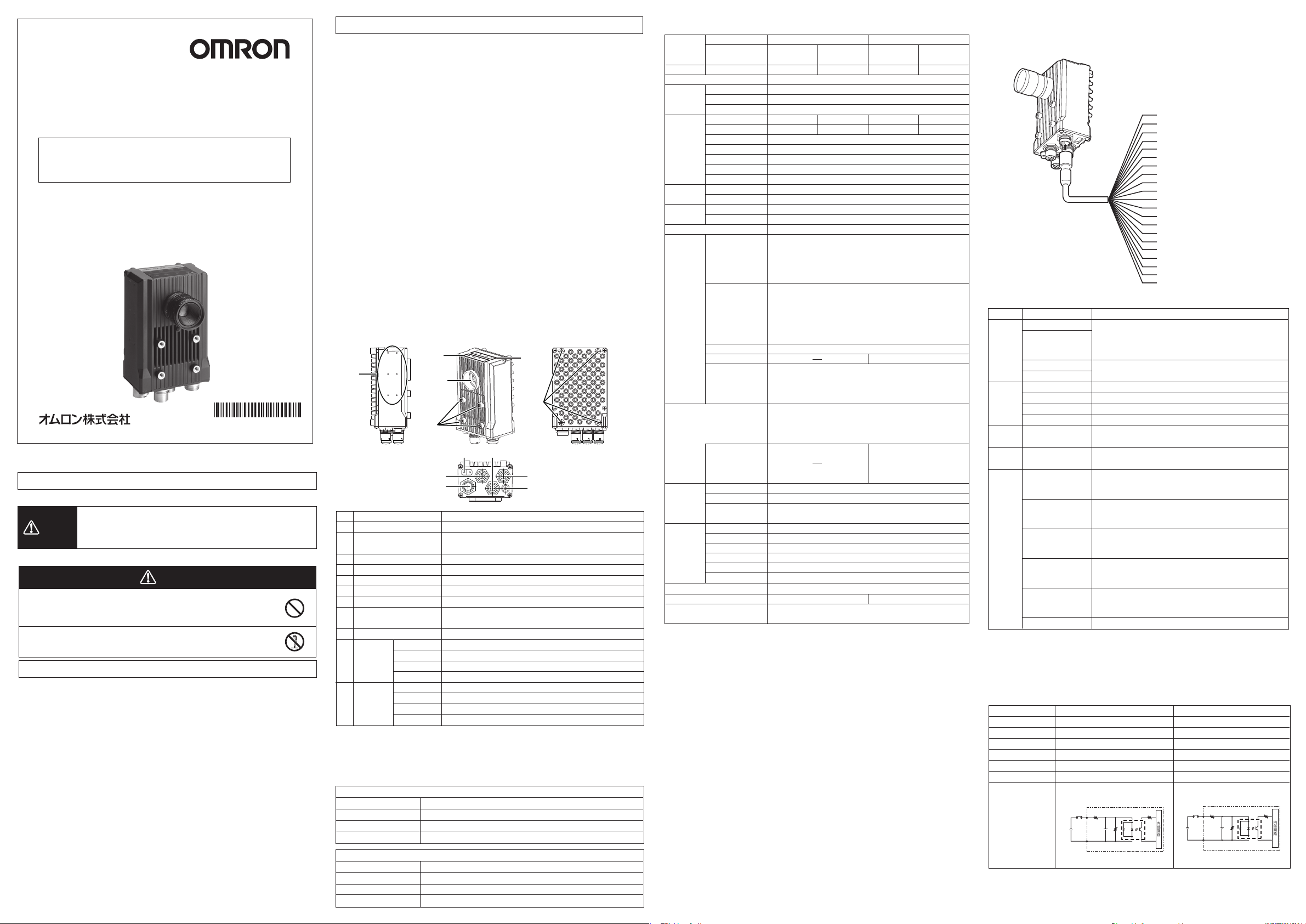
■各部の名称と機能
(9)
* 2 1 9 1 9 0 3 - 3 B *
OMRON Corporation All Rights Reserved.
©
2011-2015
安全上のご注意
●警告表示の意味
正しい取扱いをしなければ、この危険のために、軽傷・中程度
警告
の傷害を負ったり万一の場合には重傷や死亡に至る恐れがあり
ます。また、同様に重大な物的損害をもたらす恐れがあります。
●警告表示
警告
安全を確保する目的で直接的または間接的に人体を検出する用途
に本製品は使用できません。
人体保護用の検出装置として本製品を使用しないでください。
内部には高い電圧の部分があり、感電の恐れがあります。本体のカ
バ ーを 開 け な い でください 。
No.
名称
(1)
I/Oコネクタ
(2)
Ethernetコネクタ
(3)
照 明 コ ネクタ
(4)
EherCATコネクタ(入力)*1
(5)
EherCATコネクタ(出力)*1
(6)
ノードアドレス設定スイッチ*1
(7)
取り付け 穴
(8)
C マ ウ ント レ ン ズ 取 り 付 け 面
(9)
ストロボコントローラ 取り 付け 穴
(10)
計測処理
動作表示灯
安全上の要点
以下に示すような項目は安全を確保する上で必要なことですので必ず守ってください。
1.設置環境について
・引火性、爆発性ガスの環境では使用しないでください。
操作や保守の安全を確保するため、高電圧機器や動力機器から離して設置してください。
・
・取付ネジは以下の規定トルクで締め付けてください。M4:1.2N・m、M2:0.15N・m
2.電源および配線について
・次のことを行うときは故障の原因になりますので、必ずカメラ本体の電源をOFFにしてください。
・ケーブルを接続、配線するとき
・コネクタを取り付けたり、取り外したりするとき
・
ノードアドレス設定スイッチを設定するとき(FQ-MS12□-ECT、FQ-MS12□-M-ECTタイプのみ)
・電源の逆接続はしないでください。オープンコレクタ出力は、負荷を短絡させないでください。
・高圧線、動力線と当製品の配線は別配線としてください。同一配線あるいは同一ダクトにすると
誘導を受け、誤動作あるいは破損の原因になることがあります。
・負荷は定格以下で使用してください。
・指定した電源電圧で使用してください。
・配線は指定サイズの圧着端子を付けてください。撚り合わせただけの電線を直接電源や端子
台に接続しないでください。
・
電源は、高電圧が発生しないように対策(安全超低電圧回路)されている直流電源装置から供給してください。
・システム全体で、UL認定が必要なときは、ULクラスⅡの直流電源装置をお使いください。
・本製品は他の商品と一緒にせず、単独の電源で使用してください。
3 .その 他
・原子力や、人命に関わる安全回路には使用しないでください。
・本製品を分解、加圧変形、焼却、修理、改造したりしないでください。
・専用のタッチファインダ(形FQ-MD)、ケーブル(形FQ-MWD、形FQ-WN、形FQ-MWN)を使用
してください。専用品以外を使用すると誤動作や故障の原因となります。
・廃棄するときは、産業廃棄物として処理してください。
・異臭がする、本体が非常に熱くなる、煙が出るなどの異常が起こった場合、すぐに使用を中止し、
電源を切った状態で当社支店・営業所までご相談ください。
・機器表面は熱くなるため、使用中は触らないでください。
(11)
EtherCAT
動作表示灯
*1
*1形FQ-MS□□□-ECT,形FQ-MS□□□-M-ECTに対応します。
■電源接続(スイッチングレギュレータ接続時)
次の電源は推奨電源です(別売)
形FLシリーズストロボコントローラ、照明使用時
電源電圧
出力電流
推奨電源
外部電源端子台ネジ
外部照明未使用時
電源電圧
出力電流
推奨電源
外部電源端子台ネジ
使用上の注意
(10)
(8)
(7)
(6)
(4)
(1)
説明
入出力用ケーブルを使用して、センサの電源や外部装置と接続するときに使用します。
Ethernetケーブルを使用して、センサとPLCなどの外部装置、
タッチファインダまたはパソコンと接続するときに使用します。
外部照明(ストロボコントローラ)を接続します。
EtherCAT対応機と接続します。
EtherCAT対応機と接続します。
EtherCAT通信機器としての局アドレス設定に使用します。設定範囲は00〜99です。
カメラ固定用の取り付け穴です。
Cマウントレンズを取り付けます。計測物の大きさで視野を決め、
適切なCCTVレンズ(Cマウントレンズ)を選択してください。
ストロボコントローラを取り付けます。形FL-TCC1が接続できます。
OR
ETN
ERROR
BUSY
L/AIN
L/AOUT
ECATRUN
ECATERROR
OR信号がON時にオレンジ色で点灯します。
Ethernet通信時にオレンジ色で点灯します。
エラー発生時に赤色で点灯します。
センサが処理を実行中に緑色で点灯します。
EtherCAT機器と接続したときに緑色に点灯、通信(データ入力)時に緑色に点滅します。
EtherCAT機器と接続したときに緑色に点滅、通信(データ入力)時に緑色に点滅します。
EtherCAT通信可能時に緑色に点灯します。
EtherCAT通信可能時に赤色に点灯します。
DC24V(21.6〜26.4V)
1.3A以上
形S8VS-03024□(30W1.3A)
M4(締付けトルク1.2N・m)
DC24V(21.6〜26.4V)
0.65A以上
形S8VS-01524□(15W0.65A)
M4(締付けトルク1.2N・m)
(2)
(11)
(7)
(5)
(3)
■定格/性能
項目
形式
視野設置距離
主な機能
画像撮影
外部照明
データ
ロギング機 能
計 測 のトリガ
入出力仕様
LED表示灯
定格
耐環境性
材質
質量
付属品
種類
NPN
PNP
検 査 アイテ ム
同時に検査できる数
シーン登録数
画像処理方式
撮像素子
画 像 フィル タ
シャッタ 機 能
処理分解能
画 素 サ イズ
フレームレート(取込時間)
接続方法
接続照明
計測結果のロギング
画 像 の ロギング
入力信号
出力信号
Ethernet仕様
EtherCAT仕様
接続方式
EtherCAT表示灯
電源電圧
絶縁抵抗
消費電流
周囲温度範囲
周囲湿度範囲
周囲雰囲気
振動(耐久)
衝撃(耐久)
保護構造
EtherCAT非搭載タイプ
カラー
FQ-MS120
FQ-MS125
視野・設置距離に合わせてレンズを選択(光学図表参照)
形 状サーチ 、サーチ、ラベリング 、エッジ位 置
32
32
リアルカラ ー
1/3インチカラーCMOS
ハイダイナミックレンジ機能(HDR)、ホワイトバランス(カラータイプのみ)
電子シャッタ方式、シャッタスピード1/10〜1/30000(sec)
752(H)×480(V)
6.0(μm)×6.0(μm)
60fps(16.7ms)
ストロボコントローラ接 続
形FLシリーズ
センサ本体:最大32000件 *1
センサ本体:20枚 *1
I/Oトリガ、エンコーダトリガ、通信トリガ(Ethernet無手順、PLCリンク、EtherCAT経由)
9本
・単発計測入力(TRIG)
・エラークリア入力(IN0)
・エンコーダカウンタリセット入力(IN1)
・エンコーダ入力(A±,B±,Z±) * 3
5本*2
・OUT0(総合判定出力:OR)
・OUT1(制御出力:BUSY)
・OUT2(エラー出力:ERROR)
・OUT3(シャッター出力:SHTOUT)
・OUT4(ストロボ照明出力:STGOUT)
100BASE-TX/10BASE-T
専 用 コ ネクタケーブ ル
・電源、I/O制御用:専用I/Oコネクタケーブル1本
・タッチファインダ、パソコン、Ethernet制御用:Ethernetケーブル1本
・EtherCAT接続用:EtherCATケーブル2本
OR:判定結果表示灯
ERR::エラー表示灯
BUSY:BUSY表示灯
ETN::Ethernet通信表示灯
DC21.6V〜26.4V(リップル含む)
リード線一括とケース間:0.5MΩ(250Vメガについて)
450mA以下(形FLシリーズストロボコントローラ、照明使用時)
250mA以下(外部照明未使用時)
動作時:0〜50℃、保存時:−20〜+65℃(ただし、氷結、結露しないこと)
動作時、保存時:各35〜85%RH(ただし、結露しないこと)
腐食性ガスのないこと
10〜150Hz 片振幅0.35mm X/Y/Z方向 各8分10回
150m/s
IEC60529規格IP40
ケ ー ス:ア ル ミ ダ イ カ スト 、リ ア カ バ ー:ア ル ミ プ レ ート
約390g(本体のみ)
・取扱説明書(本誌)
モノク ロ
FQ-MS120-M
FQ-MS125-M
モノク ロ
1/3インチモノクロCMOS
2
6方向(上下・左右・前後)各3回
*1.タッチファインダ使用時はSDカードの容量により保存可能枚数が異なります。
*2.出力信号5本(OUT0〜4)は、各検査項目の個別判定に割り当て変更できます。
*3 .エンコーダ入力仕様を参照してください。
EtherCAT搭載タイプ
カラー
FQ-MS120-ECT
FQ-MS125-ECT
リアルカラ ー
1/3インチカラーCMOS
EtherCAT専用プロトコル100BASE-TX
・L/AIN(Link/ActivityIN)×1
・L/AOUT(Link/ActivityOUT)×1
・R U N×1
・E R R×1
約480g(本体のみ)
モノク ロ
FQ-MS120-M-ECT
FQ-MS125-M-ECT
モノク ロ
1/3インチモノクロCMOS
■配線仕様
センサ本体下部の入出力ケーブル用コネクタに、入出力ケーブルを接続します。
入出力ケーブルの各信号を配線します。
茶 24V
青 GND
茶/白 VDDENCODER
青/白 GNDENCODER
桃 TRIG
赤/白 ERRORCLR
緑/白 EFCRST
紫/白 COMI
紫 ENCODER(A−)
灰 ENCODER(A+)
緑 ENCODER(B−)
入 出 力 ケ ーブ ル
形FQ-MWD□□□/
FQ-MWDL□□□
*必要のない信号線は切断し、他の信号線と接触しないようにしてください。
区分 信号名 用途
電源 電源(24V)
入力(I/O) TRIG トリガ信号入力用端子です。
入力
(エンコーダ )
シ ー ルド 線 SHIELDENCODER
出力 OUT0(OR)
*1:撮像素子が露光終了するタイミングを外部に出力します。計測後、センサを次の計測箇所に移
* 2:
*3:外部照明を、信号がONのときに発光させるか(出力時ON)、消灯させるか(出力時OFF)を変
GND
VDDENCODER エンコーダ電源用端子です。
GNDENCODER
ERRORCLR エラークリア入力用端子です。
EFCRST エンコーダフリーカウントリセット入力端子です。
COMI TRIG、ERRORCLR、EFCRST信号用コモン端子です。
ENCODER(A±,B±,Z±)
OUT1(BUSY)
OUT2(ERROR)
OUT3(SHTOUT)
OUT4(STGOUT)
COMO OUT0〜4出力信号用コモン端子です。
動させたい場合は、本信号がOFF→ONになってから、センサを移動させてください。
撮像タイミングと同期して、外部照明を点灯させるための制御信号です。外部照明に接続してください。
更することができます。(ストロボ出力極性)
外部供給電源(24V)用端子です。
電源は他の機器とは独立して配線してください。他の機器と同一に
配線したり、同一のダクトに配線したりすると電磁誘導の影響を受
け 、セン サが 誤 動 作したり 、破 損したりする 原 因 に なります 。
使用するエンコーダの電源と同じ電源(5/12/24Vのいずれか)を接続して下さい。
エンコーダ入力用端子です。
エンコーダ信号用のシールド線です。エンコーダ電源のGND(GND
ENCODER)に接続してください。
出力用端子です。工場出荷時の設定では、OR(総合判定)信号が
出 力 信 号 とし て 割 り 付 け て あ りま す 。
OR0〜31(個別判定)信号に割付を変更することもできます。
出力用端子です。工場出荷時の設定では、BUSY(処理実行中)信号が出力信
号 とし て 割 り 付 け て ありま す 。
OR0〜31(個別判定)信号に割付を変更することもできます。出力用端子です。
出力用端子です。工場出荷時の設定では、ERROR信号が出力信
号 とし て 割 り 付 け て ありま す 。
OR0〜31(個別判定)信号に割付を変更することもできます。
出力用端子です。工場出荷時の設定では、SHTOUT(シャッタ出
力)信号(*1)が出力信号として割り付けてあります。
OR0〜31(個別判定)信号に割付を変更することもできます。
出力用端子です。工場出荷時の設定では、STGOUT(ストロボ照
明出力)信 号 (*2 *3 )が 出 力 信 号として割り付けてあります。
OR0〜31(個別判定)信号に割付を変更することもできます。
●入力(I/O)仕様
単発計測入力(TRIG)、エラークリア入力(IN0)、エンコーダカウンタリセット入力(IN1)
モ ード NPN PNP
入力電圧 DC24V±10% DC24V±10%
入力電流 7mATYP.(DC24V) 7mATYP.(DC24V)
ON電圧/ON電流*1 DC19V以上/3mA以上 DC19V以上/3mA以上
OFF電圧/OFF電流*2
O N デ ィレ イ 0.1ms以下 0.1ms以下
OFFディレイ
内部回路図
*1:ON電流/ON電圧 OFF→ON状態にさせる電流値または電圧値のことです。ON電圧の値は、
COMIと各入力(I/O)端子間の電位差になります。
*2:OFF電流/OFF電圧ON→OFF状態にさせる電流値または電圧値のことです。OFF電圧の
値は、COMIと各入力(I/O)端子間の電位差になります。
DC5V以下/1mA以下 DC5V以下/1mA以下
0.1ms以下 0.1ms以下
入力回路
各入力(I/O)端子
3.3kΩ
+
COMI
1000pF
910Ω
白 ENCODER(B+)
赤 ENCODER(Z−)
黄 ENCODER(Z+)
緑/黄 SHIELDENCODER
黒 OUT0(OR)
橙 OUT1(BUSY)
薄青 OUT2(ERROR)
黄緑 OUT3(SHTOUT)
ベージュ OUT4(STGOUT)
黒/白 COMO
入力回路
各入力(I/O)端子
内部回路
3.3kΩ
+
COMI
1000pF
910Ω
内部回路
Page 2
t15
t0
t
t0
t1
●出力(I/O)仕様
総合判定出力(OR)、制御出力(BUSY)、エラー出力(ERROR)、シャッター出力(SHTOUT)、
ストロボ照明出力(STGOUT)
モ ード NPN PNP
出力電圧 DC21.6〜30V DC21.6〜30V
負荷電流 50mA以下 50mA以下
ON残留電圧 1.2V以下 1.2V以下
OFF漏れ電流 0.1mA以下 0.1mA以下
内部回路図
出力回路
内部回路
各出力端子
COMO
L
負荷
+
出力回路
内部回路
COMO
各出力端子
+
負荷
L
*出力仕様に合った負荷を接続してください。短絡するとセンサが故障します。
●エンコーダ入力仕様
パルス入力仕様(オープンコレクタ出力タイプのエンコーダ使用時)
項目 仕様
入力電圧
入力電流
NPNタイプ 4.8V以下 2.4V以下
ON電圧 *1
OFF電圧 *2
PNPタイプ
ON電圧 *1
OFF電圧 *2
最大応答周波数 *3
DC24V±10% DC12V±10%
4.8mA(DC24V時,TYP値) 2.4mA(DC12V時,TYP値)
DC5V±5%
1.0mA(DC5V時,TYP値)
1.0V以下
19.2V以上 9.6V以上
4.0V以上
19.2V以上 9.6V以上 4.0V以上
4.8V以下 2.4V以下 1.0V以下
50kHz(入出力ケーブル:形FQ-MWD005/形FQ-MWDL005使用時)
20kHz(入出力ケーブル:形FQ-MWD010/形FQ-MWDL010使用時)
入 力 インピ ー ダンス
*1.ON電圧OFFからON状態にさせる電圧値のことです。ON電圧の値は、エンコーダ電源用端子
のGNDと各入力端子間の電位差となります。
*2.OFF電圧ONからOFF状態にさせる電圧値のことです。ON電圧の値は、エンコーダ電源用端
子のGNDと各入力端子間の電位差となります。
*3.使用するエンコーダのケーブル長、応答周波数に注意してご使用ください。
5.1kΩ
パルス入力仕様(ラインドライバ出力タイプのエンコーダ使用時)
項目 仕様
入力電圧 EIA規格 RS-422-Aラインドライバレベル
入力インピーダンス *1 120Ω±5%
差動入力電圧 0.2V以上
ヒス テリシ ス 電 圧 50mV
最大応答周波数 *2 200kHz(入出力ケーブル:形FQ-MWD005/形FQ-MWDL005
/形FQ-MWD010/形FQ-MWDL010使用時)
*1.終端対抗機能使用時
*2.使用するエンコーダのケーブル長、応答周波数に注意してご使用ください。
入力信号回路図
オープン コレクタ 入 力
NPNタイプ
オープン コレクタ 入 力
PNPタイプ
ラインドライバ
入 力 タイプ
オープンコレクタ入力タイプ(NPNタイプ)
入力回路
フォトカプラ
5.1kΩ
内部回路
オープンコレクタ入力タイプ(PNPタイプ)
内部回路
ラインドライバ入力タイプ
内部回路
入力回路
フォトカプラ
フォトカプラ
フォトカプラ
フォトカプラ
フォトカプラ
フォトカプラ
フォトカプラ
フォトカプラ
5.1kΩ
入力回路
5.1kΩ
FQ-M
*1:使用するエンコーダの電源と同じ電源(5/12/24Vのいずれか)を接続してください。
*2:120Ω抵抗はラインドライバエンコーダ接続時に使用する終端抵抗機能です。
オープンコレクタタイプのエンコーダご使用時は終端抵抗をOFFした状態でご使用ください。
(初期値:OFF)
入力回路
入力回路
5.1kΩ
入力回路
5.1kΩ
FQ-M
*1:使用するエンコーダの電源と同じ電源(5/12/24Vのいずれか)を接続してください。
*2:120Ω抵抗はラインドライバエンコーダ接続時に使用する終端抵抗機能です。
オープンコレクタタイプのエンコーダご使用時は終端抵抗をOFFした状態でご使用ください。
(初期値:OFF)
入力回路
入力回路
入力回路
FQ-M
*3:120Ω抵抗はラインドライバエンコーダ接続時に使用する終端抵抗機能です。
エンコーダ電源
(*1)
(DC24/12/5V)
茶/白VDDENCODER
紫ENCODER(A−)
(*2)
120Ω
灰ENCODER(A+)
緑ENCODER(B−)
(*2)
120Ω
白ENCODER(B+)
赤ENCODER(Z−)
(*2)
120Ω
黄ENCODER(Z+)
青/白GNDENCODER
緑/黄SHIELDENCODER
エンコーダ電源
(DC24/12/5V)
茶/白VDDENCODER
紫ENCODER(A−)
(*2)
120Ω
灰ENCODER(A+)
緑ENCODER(B−)
(*2)
120Ω
白ENCODER(B+)
赤ENCODER(Z−)
(*2)
120Ω
黄ENCODER(Z+)
5.1kΩ
青/白GNDENCODER
緑/黄SHIELDENCODER
エンコーダ電源(DC5V)
茶/白VDDENCODER
紫ENCODER(A−)
(*3)
120Ω
灰ENCODER(A+)
緑ENCODER(B−)
(*3)
120Ω
白ENCODER(B+)
赤ENCODER(Z−)
(*3)
120Ω
黄ENCODER(Z+)
青/白GNDENCODER
緑/黄SHIELDENCODER
ソフトウェアからの設定により終端抵抗機能のON/OFFが可能です。
お客様のご使用状況に応じて終端抵抗機能のON/OFFを設定頂きご使用ください。
(初期値:OFF)
+
(*1)
+
A相
B相
Z相
オープンコレクタエンコーダ
+
A相
B相
Z相
オープンコレクタエンコーダ
ラインドライバエンコーダ
(NPN)
(PNP)
−A相
+A相
−B相
+B相
−Z相
+Z相
電源
電源
電源
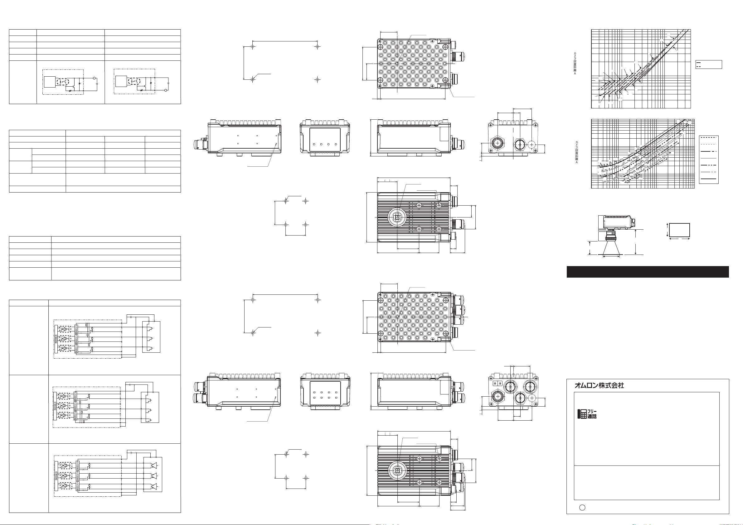
■外形寸法図
●FQ-MS12□/FQ-MS12□-M
50 ±0.1
6-M2深さ4.5max.
6-M2DEPTH4.5max.
●FQ-MS12□-ECT/FQ-MS12□-M-ECT
50 ±0.1
6-M2深さ4.5max.
6-M2DEPTH4.5max.
98 ±0.1
4- Ø 4.5
4-4.5Dia.
取付穴加工寸法(1)
MOUNTINGSCREWHOLES(1)
36 ±0.1
取付穴加工寸法(2)
MOUNTINGSCREWHOLES(2)
98 ±0.1
4- Ø 4.5
4-4.5Dia.
取付穴加工寸法(1)
MOUNTINGSCREWHOLES(1)
36 ±0.1
取付穴加工寸法(2)
MOUNTINGSCREWHOLES(2)
4- Ø 4.5
4-4.5Dia.
30 ±0.1
4- Ø 4.5
4-4.5Dia.
30 ±0.1
(単位:mm)
25.4
50
25
4.6 98
5 50.5
30
75
25.4
50
25
4.6 98
5 50.5
30
75
光軸
OPTICALAXIS
4-M4深さ8.5max.
4-M4DEPTH8.5max.
110
光軸
OPTICALAXIS
4-M4深さ7max.
4-M4DEPTH7max.
33
63 30 22.08
光軸
OPTICALAXIS
110
光軸
OPTICALAXIS
4-M4深さ7max.
4-M4DEPTH7max.
33 8.7
63 30
10.7
8.7
4-M4深さ8.5max.
4-M4DEPTH8.5max.
10.7
20.48
22.08
■光学図表
下表の値は概略数値であり、カメラは取付け後に調整が必要です。
10,000
t2
5 15.05
23.45 10.35
カメラ設置距離A
t20
t30
1,000
(mm)
28
t40
t50
t60
t10
t50
t40
200
2 10 100 400
t15
t20
t30
t5
t10
t2
t5
10,000
カメラ設置距離A
12.5
(mm)
1,000
t10
t15
t20
t35
t25
t30
t40
t25
100
30
2 10 100 1,000
t10
t15
t5
t20
t10
t15
t20
t5
t10
t1.5
t1
t2
t5
t1
t1
t2
t0.5
t5
t2
t0.5
t1.5
t2
t1
t0.5
t1.5
t2
t1
t0.5
t1
t0
ML-7527
ML-10035
t:接写リング
例)
t0:接写リングが
不要
t5:5mmの接写
リングが必要
Y視野(mm)
t0
t0
t0
0
t0
t0
ML-0614
ML-0813
ML-1214
ML-1614
ML-2514
ML-3519
ML-5018
Y視野(mm)
光学図表の見かた
図表の横軸が視野(mm)*1
18
36
縦軸がカメラ設置距離(mm)またはWD(mm)*2を表します。
視野(mm)
カメラ
接写リングt□(mm)
レンズ
WD(mm)
カメラ設置距離(mm)
視野(mm)
Y
視野
X
*1.光学図表に記載されている視野の長さはY軸
方向の長さになります。
*2.カメラの縦軸はWDを表します。
ご承諾事項
当社商品は、一般工業製品向けの汎用品として設計製造されています。従いまして、次に
掲げる用途での使用を意図しておらず、お客様が当社商品をこれらの用途に使用される際
には、当社は当社商品に対して一切保証をいたしません。ただし、次に掲げる用途であって
も当社の意図した特別な商品用途の場合や特別の合意がある場合は除きます。
(a)高い安全性が必要とされる用途(例:原子力制御設備、燃焼設備、航空・宇宙設備、鉄
道設備、昇降設備、娯楽設備、医用機器、安全装置、その他生命・身体に危険が及び
うる用途)
(b)高い信頼性が必要な用途(例:ガス・水道・電気等の供給システム、24時間連続運転
システム、決済システムほか権利・財産を取扱う用途など)
(c)厳しい条件または環境での用途(例:屋外に設置する設備、化学的汚染を被る設備、
電磁的妨害を被る設備、振動・衝撃を受ける設備など)
(d)カタログ等に記載のない条件や環境での用途
*(a)から(d)に記載されている他、本カタログ等記載の商品は自動車(二輪車含む。以下同
じ)向けではありません。自動車に搭載する用途には利用しないで下さい。自動車搭載
25.25
4.55
12.5
5 15.05
18
36
23.45
10.35
28
用商品については当社営業担当者にご相談ください。
*上記は適合用途の条件の一部です。当社のベスト、総合カタログ、データシート等最新版
のカタログ、マニュアルに記載の保証・免責事項の内容をよく読んでご使用ください。
インダストリアルオートメーションビジネスカンパニー
●製品に関するお問い合わせ先
お客様相談室
クイック オムロン
0120-919-066
携帯電話・PHS・IP電話などではご利用いただけませんので、下記の電話番号へおかけください。
電話
055-982-5015
■営業時間:8:00〜21:00 ■営業日:365日
●FAXやWebページでもお問い合わせいただけます。
FAX055-982-5051/www.fa.omron.co.jp
●その他のお問い合わせ
納期・価格・サンプル・仕様書は貴社のお取引先、または貴社
担当オムロン販売員にご相談ください。
オムロン制御機器販売店やオムロン販売拠点は、Webページで
ご案内しています。
v
A
2014年7月
(通話料がかかります)
Page 3

Model
FQ-MS12
□-□-□□□
Vision Sensor for Positioning
INSTRUCTION SHEET
Thank you for selecting OMRON product. This sheet primarily
describes precautions required in installing and operating the product.
Before operating the product, read the sheet thoroughly to
acquire sufficient knowledge of the product. For your convenience,
keep the sheet at your disposal.
TRACEABILITY INFORMATION:
Importer in EU Manufacturer:
Omron Europe B.V. Omron Corporation,
Wegalaan 67-69 Shiokoji Horikawa, Shimogyo-ku,
2132 JD Hoofddorp, Kyoto 600-8530 JAPAN
The Netherlands
• Regulation of KC marking
A급 기기(업무용 방송통신기자재)
이 기기는 업무용(A급) 전자파적합기기로서 판매자
또는 사용자는 이 점을 주의하시기 바라며,가정외의
지역에서 사용하는 것을 목적으로 합니다.
OMRON Corporation All Rights Reserved.
©
2011-2015
PRECAUTIONS ON SAFETY
Indicates a potentially hazardous situation which, if not avoided, will
WARNING
result in minor or moderate injury, or may result in serious injury or
death. Additionally there may be significant property damage.
WARNING
This product is not designed or rated for ensuring safety
of persons either directly or indirectly. Do not use it for such purpose.
High voltage part inside the unit may cause electric shock.
Do not open the cover of the unit.
PRECAUTIONS FOR SAFE USE
Always follow the rules below to ensure safety.
1. Installation environment
• Do not use in a location where there is flammable or explosive gas.
• To ensure safe operation and maintenance, install away from high-voltage equipment and
power equipment.
• Tighten the mounting screws with the specified torque: M4: 1.2 N·m, M2: 0.15 N·m
2. Power and cable connections
• Be sure to turn OFF the power of the camera unit as it may result in malfunction when taking
the following actions.
• Connecting or wiring cables
• Mounting or removing connectors
•
Setting the node address setting switch (FQ-MS12□-ECT and FQ-MS12□-M-ECT types
only)
• Do not reverse the polarity of the power connection. Do not short the load of the open
collector output.
• Wire this product separately from the wiring of high-voltage wires and power wires. If wired
together or in the same conduit, induction may occur and cause malfunctioning or damage.
• Use a load that is equal to or less than the rating.
• Use the specified power voltage.
• Use the specified size of crimp terminals for wiring connections. Do not connect wires that
have been simply twisted together directly to the power supply or terminal block.
• Supply power from a DC power supply for which measures have been applied to prevent high
voltages (e.g., a safety extra low voltage circuit).
• If UL certification is required for the overall system, use a UL Class II DC power supply.
• Use an independent power source for this product. Do not use a shared power source.
3. Other Rules
• Do not use in safety circuits for atomic energy or that are critical for human life.
• Do not attempt to disassemble, deform by pressure, incinerate, repair, or modify this product.
* 2 1 9 1 9 0 3 - 3 B *
• Use the FQ-MD Touch Finder and the FQ-WN or FQ-WD Cable. Sensor malfunction or
damage may occur if any other devices or cables are used.
• When disposing of the product, treat as industrial waste.
• If you notice an abnormal condition such as a strange odor, extreme heating of the unit, or
smoke, immediately stop using the product, turn off the power, and consult your dealer.
• The device surface becomes hot during use. Do not touch during use.
PRECAUTIONS FOR CORRECT USE
Observe the following to prevent failure, malfunctioning, and adverse effects on performance and
the device.
1. Installation site
• Do not install in the following locations:
• Locations where the ambient temperature exceeds the rated temperature range.
• Locations subject to sudden temperature changes (where condensation will form).
• Locations where the relative humidity is below or above 35 to 85% RH.
• Locations where there are corrosive or flammable gases.
• Locations where there is dust, salt, or iron powder.
• Locations where the device will be subject to direct vibration or shock.
• Locations where there is strong scattered light (laser light, arc welding light, ultraviolet light,
etc.)
• Locations exposed to direct sunlight or next to a heater.
• Locations where there is splashing or spraying of water, oil, or chemicals.
• Locations where there is a strong electrical or magnetic field.
2. Power and cable connections
• When using a switching regulator, ground the FG pin of the switching regulator.
• If there are surges on your power line, connect a surge absorber as appropriate for your
conditions of use.
• Before turning on the power after the wiring is completed, verify that the power is correct, that
there are no incorrect connections such as a shorted load circuit, and that the load current is
suitable. Incorrect wiring may cause damage and failures.
3. Optical axis and detection range
There is a certain amount of deviation among sensors in the center of the optical axis. For this
reason, when installing the sensor, be sure to check the center of the image and the detection
range in the LCD monitor of the Touch Finder and in the sensor software.
4. Maintenance and inspection
• Do not use thinner, alcohol, benzene, acetone, or kerosene to clean the sensor or Touch Finder.
• If considerable foreign matter or dust collects on the panel on the front of the senor, use a
blower brush (for camera lenses) to blow off the foreign matter. Avoid blowing it off with your
breath.
• For a small amount of foreign matter or dust, gently wipe with a soft cloth. Do not wipe hard.
If the surface is damaged, false detection may result.
5. Connector cover
Attach the covers of I/O cable connector and Ethernet cable connector. Be sure that they are
fixed when attached. This prevents extraneous material from making malfunction of sensor.
6. Pixel defects
• Although this product may have defective pixels due to CMOS image sensor (light receiving
element) specifications, it is not considered a product defect or malfunction.
7. LED indicators are covered with protection sheets with shipment. Peel them off before using.
(9)
(10)
(8)
(11)
(7)
(7)
Line driver input type
(6)
(2)
(4)
(1)
No.
Name
(1)
I/O connector
(2)
Ethernet connector
(3)
Lighting connector Connects an external lighting (Lighting controller).
(4) Connects an EtherCAT compatible device.
EherCAT connector (IN)*1
(5)
EherCAT connector (OUT)*1
Node address setting switch *1
(6)
(7) Mounting hole
(8) C mount lens mounting
surface
(9)
Flash controller mounting hole
(10)
Measurement
operation
indicator
EtherCAT
operation
indicator *1
*1 Supports FQ-MS□□□-ECT and FQ-MS□□□-M-ECT.
OR
ETN
ERROR
BUSY
L/A IN
L/A OUT
ECAT RUN
ECAT ERROR
Description
An I/O Cable is used to connect the Sensor to the power supply and external devices.
An Ethernet cable is used to connect the Sensor to an external
device, such as a PLC, Touch Finder or computer.
Connects an EtherCAT compatible device.
Used to set the node address as an EtherCAT communication device.
Setting range is 00 to 99.
Used for fixing the camera.
C mount lens is mounted. Decide a field of view based on the size of
a measuring object and select a proper CCTV lens (C mount lens).
Used for a flash controller. FL-TCC1 can be connected.
Lights in orange when the OR signal turns ON.
Lights in orange during Ethernet communication.
Lights in red when an error occurs.
Lights in green when the Sensor is executing a process.
Lights in green when connected to a EtherCAT device or blinks
in green during communication (data input).
Blinks in green when connected to a EtherCAT device or blinks
in green during communication (data input).
Lights in green when EtherCAT communication is available.
Lights in red when EtherCAT communication is available.
(5)
(3)
The following power supply is recommended (option).
When a FL series flash controller and lighting are used
Power supply voltage
Output current
Recommended power supply
External power supply terminal screws
When an external lighting is not used
Power supply voltage
Output current
Recommended power supply
External power supply terminal screws
Item
Model
Field of view/installation distance
Main
functions
Image
input
External
lighting
Data
logging
Measurement trigger
I/O
specifications
Type
NPN
PNP
Inspection items
No. of simultaneous
inspections
No. of registered scenes
Image processing
method
Image elements
Image filter
Shutter
Processing resolution
Pixel size
Frame rate (capture time)
Connection
Connecting lighting
Measurement result
Images
Input signals
24 VDC (21.6 to 26.4 V)
1.3 A min.
S8VS-03024 (30 W 1.3 A)
M4 (tightening torque 1.2 N·m)
24 VDC (21.6 to 26.4 V)
0.65 A min.
S8VS-01524 (15 W 0.65 A)
M4 (tightening torque 1.2 N·m)
Sensor without EtherCAT
Color
FQ-MS120
FQ-MS125
Select a lens according to the field of view and installation
distance (see the Optical Diagram).
Shape search, search, labeling, edge position
32
32
Real color
1/3-inch color CMOS
HDR (High Dynamic Range), white balance (color type only)
Electronic shutter, shutter speed: 1/10 to 1/30,000 (sec)
752 (H) x 480 (V)
6.0 (μm) x 6.0 (μm)
60 fps (16.7 ms)
Lighting controller
FL Series
In Sensor: 32,000 items max. *1
In Sensor: 20 images *1
I/O trigger, encoder trigger, communication trigger, (Ethernet
non-procedural, PLC link, via EtherCAT)
9 signals
Monochrome
FQ-MS120-M
FQ-MS125-M
Monochrome
1/3-inch monochrome CMOS
Sensor with EtherCAT
Color
FQ-MS120-ECT
FQ-MS125-ECT
Real color
1/3-inch color CMOS
Monochrome
FQ-MS120-M-ECT
FQ-MS125-M-ECT
Monochrome
1/3-inch monochrome CMOS
• Single measurement input (TRIG)
• Error clear input (IN0)
• Encoder counter reset input (IN1)
• Encoder input (±A, ±B, ±Z) *3
Output signals
5 signals *2
• OUT0 (Overall judgment output: OR)
• OUT1 (Control output: BUSY)
• OUT2 (Error output: ERROR)
• OUT3 (Shutter output: SHTOUT)
• OUT4 (Flash lighting output: STGOUT)
Ethernet specifications
EtherCAT specifications
Connection
method
LED indicators
EtherCAT
indicators
100BASE-TX/10BASE-T
Special connector cables
•
Power supply and I/O control: 1 special I/O connector cable
•
Touch finder, PC, Ethernet control: 1 Ethernet cable
•
EtherCAT connection: 2 EtherCAT cables
OR: Judgment result indicator (Color: Orange)
ERR: Error indicator (Color: Red)
BUSY:BUSY
ETN: Ethernet communication indicator (Color: Green)
indicator
(Color: Green)
EtherCAT special protocol 100BASE-TX
• L/A IN (Link/Activity IN) × 1
•
L/A OUT (Link/Activity OUT) × 1
• RUN × 1
• ERR × 1
Ratings
Environmental
immunity
Materials
Weight
Accessories
*1. When using the touch finder, the number of items that can be stored differs depending
*2. The five output signals (OUT0 to 4) can be allocated for the judgments of individual
*3. Refer to the encoder input specifications.
Power supply voltage
Insulation resistance
Current consumption
Ambient temperature
range
Ambient humidity range
Ambient atmosphere
Vibration resistance
(destruction)
Shock resistance
(destruction)
Degree of protection
on the capacity of the SD card.
inspection items.
21.6 to 26.4 VDC (including ripple)
Between all lead wires and case: 0.5 MΩ (at 250 V)
450 mA max. (FL Series Lighting Controller and lighting used)
250 mA max. (External lighting not used)
Operating: 0 to 50°C, storage: -20 to 65°C (no icing or
condensation)
Operating and storage: 35% to 85% (with no condensation)
No corrosive gas
10 to 150 Hz, single amplitude: 0.35 mm, X/Y/Z
directions 8 min each, 10 times
2
3 times each in 6 direction (up, down, right,
150 m/s
left, forward, and backward)
IEC 60529 IP40
Case: Aluminum die-cast, rear cover: aluminum plate
Approx. 390 g(mainunitonly)
Instruction Manual (this document)
Approx. 480 g (main unit only)
Connect an I/O cable into the I/O cable connector at the bottom of the Sensor unit. Wire each
signal of the I/O cable.
Brown 24V
Blue GND
Brown/White VDD ENCODER
Blue/White GND ENCODER
Pink TRIG
Red/White ERROR CLR
Green/White EFC RST
Purple/White COM_I
Purple ENCODER(A–)
Gray ENCODER(A+)
Green ENCODER(B–)
I/O cable
FQ-MWD□□□/
FQ-MWDL□□□
White ENCODER(B+)
Red ENCODER(Z–)
Yellow ENCODER(Z+)
Green/Yellow SHIELD ENCODER
Black OUT0(OR)
Orange OUT1(BUSY)
Light Blue OUT2(ERROR)
Yellow Green OUT3(SHTOUT)
Beige OUT4(STGOUT)
Black/White COM_O
* Cut off the unnecessary signal wires to avoid contacting from other signal wires.
Category Signal name Application
Power
supply
Input (I/O)
Input
(Encoder)
Shield wire
Output OUT0 (OR)
*1: A timing when an exposure of imaging elements is finished is output to the outside. If you want to move the
*2: A control signal to turn ON the external lighting in synchronization with the imaging timing.
*3: You can change whether flashing (ON during output) or turning OFF (OFF during output) the external
Power supply (24 V)
GND
VDD ENCODER
GND ENCODER
TRIG A terminal for trigger signal input.
ERROR CLR A terminal for error clear input.
EFC RST An encoder free count reset input terminal.
COM_I
ENCODER (±A, ±B, ±Z)
SHIELD ENCODER
OUT1 (BUSY)
OUT2 (ERROR)
OUT3 (SHTOUT)
OUT4 (STGOUT)
COM_O A common terminal for OUT0 to 4 output signals.
Sensor to the next measurement location after measurement, move it after this signal changes from OFF to
ON.
lighting when the signal is ON. (Flash output polarity)
Terminals for an external power supply (24 V).
Wire the power supply separating from other devices. Wiring
them with other devices or to the same duct causes malfunction
or damage of the Sensor due to electromagnetic induction.
Terminals for encoder power supply. Connect the same power
supply (ether 5, 12 or 24 V) with the power supply of the encoder used.
A common terminal for TRIG, ERROR_CLR and EFC_RST signal.
A terminal for encoder input.
A shield wire for encoder signal. Connect it to GND (GND
ENCODER) of the encoder power supply.
A terminal for output. In the factory default, the OR (overall
judgment) signal is allocated as an output signal. Allocation can
be changed to OR0 to 31 (individual judgment) signals.
A terminal for output. In the factory default, the BUSY (executing
processing) signal is allocated as an output signa. Allocation can
be changed to OR0 to 31 (individual judgment) signals.
A terminal for output. In the factory default, the ERROR signal is
allocated as an output signal. Allocation can be changed to
OR0 to 31 (individual judgment) signals.
A terminal for output. In the factory default, SHTOUT (shutter
output) signal (
can be changed to OR0 to 31 (individual judgment) signals.
A terminal for output. In the factory default, STGOUT (flash lighting
output) signal (
can be changed to OR0 to 31 (individual judgment) signals.
*
1) is allocated as an output signal. Allocation
*
2, *3) is allocated as an output signal. Allocation
Single measurement input (TRIG), error clear input (IN0), encoder counter reset input (IN1)
Mode NPN PNP
Input voltage
Input current
ON voltage/ON current*1
OFF voltage/OFF current*2
ON delay
OFF delay 0.1 ms max. 0.1 ms max.
Internal
circuit
diagram
*1: ON current/ON voltage: A current value or voltage value that changes the status from OFF
to ON. The ON voltage value is the potential difference between COM_I and each input
(I/O) terminal.
*2: OFF current/OFF voltage: A current value or voltage value that changes the status from ON
to OFF. The OFF voltage value is the potential difference between COM_I and each input
(I/O) terminal.
24 VDC±10% 24 VDC±10%
7 mA TYP. (24 VDC) 7 mA TYP. (24 VDC)
19 VDC min./3 mA min. 19 VDC min./3 mA min.
5 VDC max./1 mA max. 5 VDC max./1 mA max.
0.1 ms max. 0.1 ms max.
Input circuit
Each input (I/O)
terminal
+
3.3 kΩ
COM_I
1000pF
910Ω
Input circuit
Internal circuit
Each input (I/O)
terminal
+
3.3 kΩ
COM_I
1000pF
910Ω
Internal circuit
Page 4

Overall judgment output (OR), control output (BUSY), error output (ERROR),
shutter output (SHTOUT), flash lighting output (STGOUT)
Mode NPN PNP
Output voltage 21.6 to 30 VDC 21.6 to 30 VDC
Load current 50 mA max. 50 mA max.
ON residual voltage
OFF leakage current
1.2 V max. 1.2 V max.
0.1 mA max. 0.1 mA max.
Internal
circuit
diagram
* Connect a load corresponding to the output specifications. Short-circuiting the
terminals may damage the Sensor.
Output circuit
Internal
circuit
Each output terminal
L
Load
+
COM_O
Output circuit
Internal
circuit
COM_O
Load
L
Each output terminal
+
Pulse input specifications (when the open collector output type is used.)
Item Specifications
Input voltage 24 VDC±10% 12 VDC±10%
Input current
NPN type 4.8 V max. 2.4 V max.
ON voltage *1
OFF voltage *2
PNP type
ON voltage *1
OFF voltage *2
Max. response frequency
*3
Input impedance
*1. A voltage value that changes the ON voltage from OFF to ON. ON voltage value is the
potential difference between GND of the terminal for encoder power supply and each input
terminal.
*2. A voltage value that changes the OFF voltage from ON to OFF. ON voltage value is the
potential difference between between GND of the terminal for encoder power supply and each
input terminal.
*3. Pay attention to the cable length and response frequency of the encoder to be used.
4.8 mA (24 VDC, TYP value)
2.3 mA (12 VDC, TYP value)
19.2 V min. 9.6 V min.
19.2 V min. 9.6 V min. 4 V min.
4.8 V max. 2.4 V max. 1.0 V max.
50 kHz (I/O cable: FQ-MWD005/FQ-MWDL005 is used)
20 kHz (I/O cable: FQ-MWD010/FQ-MWDL010 is used)
5.1 kΩ
DC5V±5%
1.0 mA (5 VDC, TYP value)
1.0 V max.
4 V min.
Pulse input specifications (when the line driver output type encoder is used)
Item Specifications
Input voltage EIA standards RS-422-A line driver level
Input impedance *1 120Ω±5%
Differential input voltage
0.2 V min.
Hysteresis voltage 50 mV
Max. response frequency *2
*1. The termination resistance function is used.
*2. Pay attention to the cable length and response frequency of the encoder to be used.
200 kHz (I/O cable: FQ-MWD005/FQ-MWDL005/FQ-MWD010/
FQ-MWDL010 is used)
Input signal circuit diagram
Open collector input
NPN type
Open collector input
PNP type
Line driver input
type
Open collector input type (NPN type)
Photocoupler
Photocoupler
Photocoupler
Internal circuit
Open collector input type (PNP type)
Photocoupler
Photocoupler
Photocoupler
Internal circuit
Line driver input type
Photocoupler
Photocoupler
Photocoupler
Internal circuit
Brown/White VDD ENCODER
5.1kΩ
120 Ω
Input circuit
5.1kΩ
120 Ω
5.1kΩ
120 Ω
Input circuit Input circuit
Blue/White GND ENCODER
Green/Yellow SHIELD ENCODER
FQ-M
Note 1: Connect the same power supply (5, 12 or 24 V) as the encoder to be used.
Note 2: The 120 Ω resistance is a termination resistance function used to connect
120 Ω
Input circuit
5.1 kΩ
120 Ω
5.1 kΩ
120 Ω
Input circuit Input circuit
5.1 kΩ
Green/Yellow SHIELD ENCODER
FQ-M
Note 1: Connect the same power supply (5, 12 or 24 V) as the encoder to be used.
Note 2: The 120 Ω resistance is a termination resistance function used to
Encoder power supply (5 VDC)
Brown/White VDD ENCODER
120Ω
Input circuit
120Ω
Input circuitInput circuit
120Ω
Green/Yellow SHIELD ENCODER
FQ-M
Note 3: The 120 Ω resistance is a termination resistance function used to
Encoder power supply
(24/12/5 VDC)
Purple ENCODER (A-)
(Note 2)
Gray ENCODER (A+)
Green ENCODER (B-)
(Note 2)
White ENCODER (B+)
Red ENCODER (Z-)
(Note 2)
Yellow ENCODER (Z+)
a line driver encoder. When using an encoder with open collector type, set
the termination resistance to OFF. (Initial value: OFF)
Encoder power supply
(24/12/5 VDC)
Brown/White VDD ENCODER
Purple ENCODER (A-)
(Note 2)
Gray ENCODER (A+)
Green ENCODER (B-)
(Note 2)
White ENCODER (B+)
Red ENCODER (Z-)
(Note 2)
Yellow ENCODER (Z+)
Blue/White GND ENCODER
connect a line driver encoder. When using an encoder with open
collector type, set the termination resistance to OFF. (Initial value: OFF)
Purple ENCODER (A-)
(Note 3)
Gray ENCODER (A+)
Green ENCODER (B-)
(Note 3)
White ENCODER (B+)
Red ENCODER (Z-)
(Note 3)
Yellow ENCODER (Z+)
Blue/White GND ENCODER
connect a line driver encoder. The termination resistance function can be
ON/OFF through the software settings.Set the termination resistance
function ON/OFF according to your usage. (Initial value: OFF)
(Note 1)
(Note 1)
+
+
+
Power
supply
Phase A
Phase B
Phase Z
Open collector encoder
(NPN)
Power
supply
Phase A
Phase B
Phase Z
Open collector encoder
(PNP)
Power
supply
Phase -A
Phase +A
Phase -B
Phase +B
Phase -Z
Phase +Z
Line driver encoder
●FQ-MS12□/FQ-MS12□-M
50 ±0.1
6-M2 DEPTH4.5 max.
50 ±0.1
6-M2 DEPTH4.5 max.
98 ±0.1
4-4.5 Dia.
MOUNTING SCREW HOLES(1)
36 ±0.1
MOUNTING SCREW HOLES(2)
98 ±0.1
4-4.5 Dia.
MOUNTING SCREW HOLES(1)
36 ±0.1
MOUNTING SCREW HOLES(2)
4-4.5 Dia.
30 ±0.1
4-4.5 Dia.
30 ±0.1
(Unit: mm)
25.4
50
25
4.6 98
5 50.5
(30)
75
25.4
50
25
4.6 98
5 50.5
(30)
75
OPTICAL AXIS
4-M4 DEPTH 8.5 max.
110
OPTICAL AXIS
4-M4 DEPTH 7 max.
33
63 30 22.08
OPTICAL AXIS
110
OPTICAL AXIS
4-M4 DEPTH 7 max.
33 8.7
63 30
10.7
8.7
4-M4 DEPTH 8.5 max.
10.7
20.48
22.08
The diagram below shows rough values. You need to adjust the camera after mounting.
t: Closeup ring
Example)
t0: Closeup ring not
required.
t5: A 5-mm closeup
ring is required.
Y field of view (mm)
23.45 10.35
Camera installation distance A (mm)
28
How to look at the Optical Diagram
12.5
5 15.05
18
36
The horizontal axis shows the field of view (mm). *1
The vertical axis shows the camera installation distance (mm) or WD (mm). *2
Fieldofview(mm)
Camera
Closeup ring t□ (mm)
Lens
WD(mm)
Camera installation distance (mm)
Fieldofview(mm)
Field of view
Y
(mm)
X
*1. The length of the field of view described on
the Optical Diagram represents the length
in the Y axis direction.
*2. The vertical axis of the camera represents WD.
Suitability for Use
Omron Companies shall not be responsible for conformity with any standards,
codes or regulations which apply to the combination of the Product in the
Buyer’s application or use of the Product. At Buyer’s request, Omron will
provide applicable third party certification documents identifying ratings and
limitations of use which apply to the Product. This information by itself is not
sufficient for a complete determination of the suitability of the Product in
combination with the end product, machine, system, or other application or
use. Buyer shall be solely responsible for determining appropriateness of the
particular Product with respect to Buyer’s application, product or system.
Buyer shall take application responsibility in all cases.
NEVER USE THE PRODUCT FOR AN APPLICATION INVOLVING
25.25
4.55
12.5
(5) 15.05
18
36
23.45
10.35
28
SERIOUS RISK TO LIFE OR PROPERTY WITHOUT ENSURING THAT THE
SYSTEM AS A WHOLE HAS BEEN DESIGNED TO ADDRESS THE RISKS,
AND THAT THE OMRON PRODUCT(S) IS PROPERLY RATED AND
INSTALLED FOR THE INTENDED USE WITHIN THE OVERALL
EQUIPMENT OR SYSTEM.
See also Product catalog for Warranty and Limitation of Liability.
OMRON Corporation
Tokyo, JAPAN
Regional Headquarters
OMRON EUROPE B.V.
Sensor Business Unit
Carl-Benz-Str. 4, D-71154 Nufringen, Germany
Tel: (49) 7032-811-0/Fax: (49) 7032-811-199
OMRON ELECTRONICS LLC
2895 Greenspoint Parkway, Suite 200
Hoffman Estates, IL 60169 U.S.A.
Tel: (1) 847-843-7900/Fax: (1) 847-843-7787
OMRON ASIA PACIFIC PTE. LTD.
No. 438A Alexandra Road # 05-05/08 (Lobby 2),
Alexandra Technopark,
Singapore 119967
Tel: (65) 6835-3011/Fax: (65) 6835-2711
OMRON (CHINA) CO., LTD.
Room 2211, Bank of China Tower,
200 Yin Cheng Zhong Road,
PuDong New Area, Shanghai, 200120, China
Tel: (86) 21-5037-2222/Fax: (86) 21-5037-2200
s
Oct, 2014
D
Industrial Automation Company
Contact: www.ia.omron.com
 Loading...