

Page 1
製品が動作不能、誤動作、または性能・機器への悪影響を防ぐため、以下のことを守ってください。
1.設置場所について
次のような場所には設置しないでください。
・周囲温度が定格の範囲を越える場所
・温度変化が急激な場所(結露する場所)
形
FQ-CR2
・相対湿度が35〜85%RHの範囲を超える場所
・腐食性ガス、可燃性ガスがある場所
・塵埃、塩分、鉄粉がある場所
・振動や衝撃が直接加わる場所
固定式2次元コードリーダ
・強い外乱光(レーザ光、アーク溶接光、紫外光など)があたる場所
・直射日光があたる場所や暖房器具のそば
・水・油・化学薬品の飛沫やミスト雰囲気がある場所
・強磁界、強電界がある場所
2.電源および接続、配線について
取扱説明書
・スイッチングレギュレータをご使用の際は、スイッチングレギュレータのFG端子を接地してください。
・電源ラインにサージがある場合は使用環境に応じてサージアブソーバを接続してご使用ください。
・配線後は電源を投入する前に、電源の正誤、負荷短絡などの誤接続の有無、負荷電流の適否
について確認を行ってください。誤配線などで故障するおそれがあります。
このたびは,本製品をお買い上げいただきまして,まことにありがとうございます。
ご使用に際しては,次の内容をお守りください。
・電気の知識を有する専門家がお取扱いください。
・この取扱説明書をよくお読みになり,十分にご理解のうえ,正しくご使用ください。
・この取扱説明書はいつでも参照できるように大切に保管してください。
3.光軸、検出範囲について
光軸中心はセンサごとにばらつくことがありますので、取付けるときは必ずタッチファインダの液晶モ
ニタ及び専用ソフトの画像表示で画像の中心と検出範囲を確認してください。
4.ピント調整ボリュームについて
ピント調整ボリュームは0.1N・m以下で回してください。破損する恐れがあります。
5.保守点検について
センサやタッチファインダの清掃には、シンナー、アルコール、ベンジン、アセトン、灯油類は使用しないでください。
・
・センサ前 面 の パネルに、大きなゴミやホコリが 付いた場合は 、ブロアブラシ(カメラレンズ用 )で吹き飛
ばし て ください 。呼 気 で 吹 き 飛 ば す こ と は 避 け て くだ さ い 。
・ 小さな ゴミや ホコリは 、柔 らかい 布 で 丁 寧 に ふきとってください 。強 くふくことは 避 け てください 。キ ズ
がつくと、誤検出の原因になります。
6 . コネクタキャップに つ い て
ケーブ ル を 外してい る時 は 必 ず コネクタキャップを装 着してください 。コネクタキャップを外 すと異 物
の侵入により誤動作するおそれがあります。
7.画素欠陥について
・本製品はCMOSイメージセンサ(受光素子)の仕様上、画素欠陥が複数存在することがあります
が、製品の欠陥や故障ではありません。
8 .カ メ ラ 設 置 に つ い て
・高温度で温度変化が激しい環境下において、前面プレート内部がまれに曇る恐れがあります。
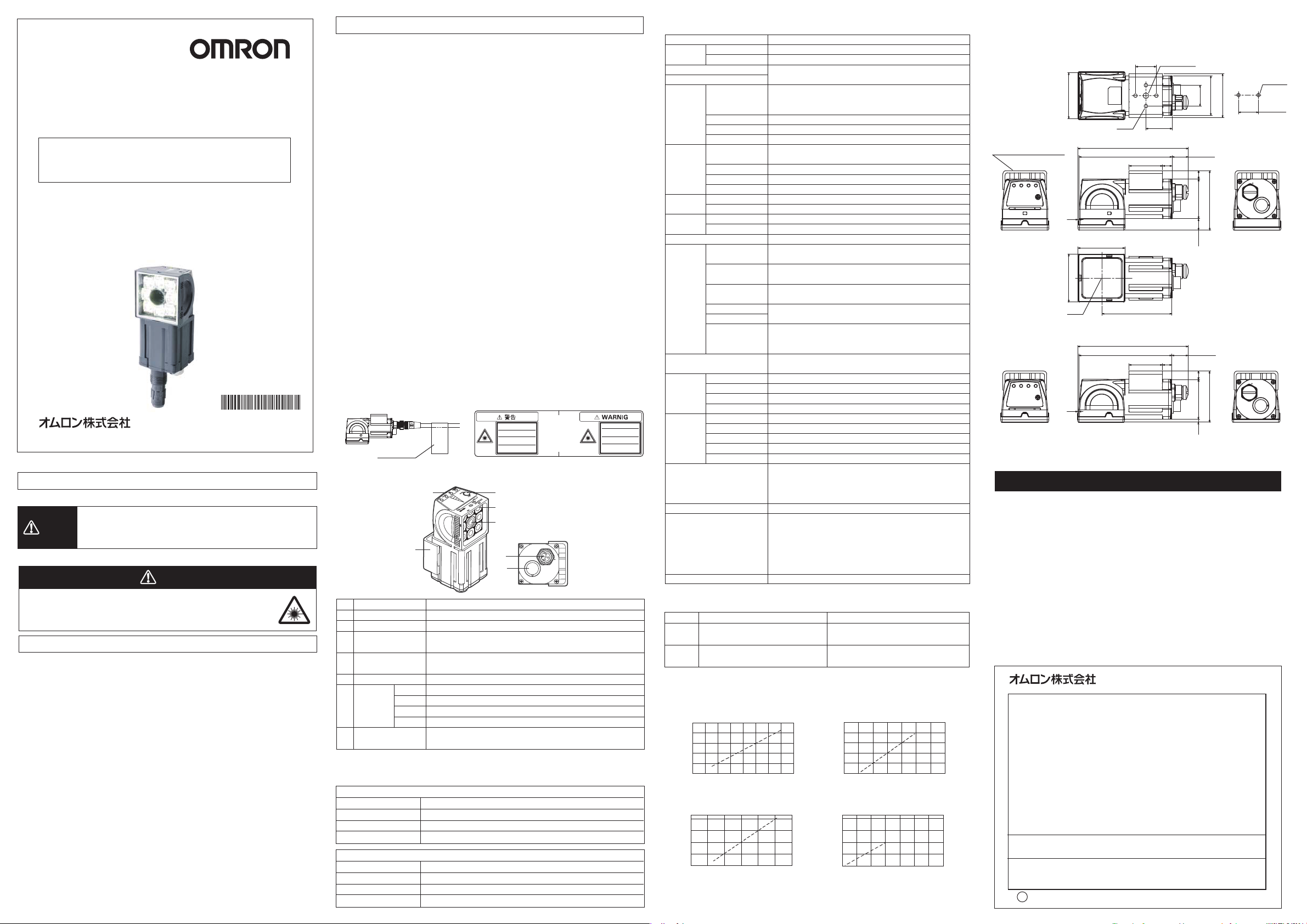
■LED警告ラベルの貼付
付属品の警告ラベルをケーブル等に貼り付けてください。必ず製品のそばで見える位置に貼り付けてください。
貼付例 警告ラベル
* 2 1 9 1 0 0 7 - 9 A *
OMRON Corporation All Rights Reserved.
©
2011
安全上のご注意
①
■各部の名称と機能
●警告表示の意味
正しい取扱いをしなければ、この危険のために、軽傷・中程度
警告
の傷害を負ったり万一の場合には重傷や死亡に至る恐れがあり
ます。また、同様に重大な物的損害をもたらす恐れがあります。
●警告表示
警告
センサは可視光を放射しており、まれに目に悪影響を及ぼす恐れがあ
ります。センサの照射光を直視しないでください。被写体が鏡面反射
体の場合は、反射光が目に入らないようにしてください。
安全上の要点
以下に示すような項目は安全を確保する上で必要なことですので必ず守ってください。
1.設置環境について
・引火性、爆発性ガスの環境では使用しないでください。
操作や保守の安全を確保するため、高電圧機器や動力機器から離して設置してください。
・
・取付ネジは、本書に記載されている規定のトルクで締め付けてください。
2.電源および配線について
・ケーブルを脱着 するときは必ず本 体の 電源を切ってください。
・電源の逆接続はしないでください。オープンコレクタ出力は、負荷を短絡させないでください。
・高圧線、動力線と当製品の配線は別配線としてください。同一配線あるいは同一ダクトにすると
誘導を受け、誤動作あるいは破損の原因になることがあります。
・負荷は定格以下で使用してください。
・指定した電源電圧で使用してください。
・配線は指定サイズの圧着端子を付けてください。撚り合わせただけの電線を直接電源や端子
台に接続しないでください。
・電源は、高電圧が発生しないように対策(安全超低電圧回路)されている直流電源装置から
供 給 し て ください 。
・システム全体で、UL認定が必要なときは、ULクラスⅡの直流電源装置をお使いください。
・本製品は他の商品と一緒にせず、単独の電源で使用してください。
3 .その 他
・原子力や、人命に関わる安全回路には使用しないでください。
・本製品を分解、加圧変形、焼却、修理、改造したりしないでください。
・専用のタッチファインダ(形FQ-D)、ケーブル(形FQ-WN、形FQ-WD)を使用してください。専
用品以外を使用すると誤動作や故障の原因になります。
・廃棄するときは、産業廃棄物として処理してください。
・異臭がする、本 体が非常に熱くなる、煙が出るなどの異常が起こった場合、すぐに使用を中止し、
電源を切った状態で当社支店・営業所までご相談ください。
・機器表面は熱くなるため、使用中は触らないでください。
No.
名称
(1)
照明部
(2)
受光部
(3)
入 出 力 ケ ーブル 用
コネクタ
(4)
イ ー サ ネ ット ケ ー ブ ル 用
コネクタ
(5)
ピ ント 調 整 ボ リ ュ ー ム
(6)
動作表示灯
(7)
取付用金具
■電源接続(スイッチングレギュレータ接続時)
次の電源は推奨電源です(別売)
FQ-CR2□010F-M/FQ-CR2□050F-M
電源電圧
出力電流
推奨電源
外部電源端子台ネジ
FQ-CR2□100F-M/FQ-CR2□100N-M
電源電圧
出力電流
推奨電源
外部電源端子台ネジ
警告ラベル
(7)
OR
ETN
ERROR
BUSY
使用上の注意
LED放射
ビームをのぞき込まないこと
Max.65mW
400-700nm
ク ラス 2 LE D 製 品
JIS C 6802:2005
(6)
説明
照明用のLEDがこの部分に取り付けられています。
この部分から画像を取り込みます。
入出力ケーブルを使用して、センサの電源や外部装置と接続するときに使
用します 。
イ ー サ ネ ット ケ ー ブ ル を 使 用 し て 、セ ン サ と タ ッ チ フ ァ イ ン ダ ま た は パ ソ コ ン と
接続するときに使用します。
撮影画像のピントを調整するときに使用します。
OR信号がON時にオレンジ色で点灯します。
イーサネット通信時にオレンジ色で点灯します。
エラー発生時に赤色で点灯します。
センサが処理を実行中に緑色で点灯します。
センサを固定するために使用します。取付用金具はセンサの前面、右側面、
左側面、背面の4方向すべてに取り付けることができます。
(5)
(1)
(2)
(4)
(3)
DC24V(21.6〜26.4V)
1.25A以上
形S8VS-030024□(DC24V1.25A)
M4(締付けトルク1.2N・m)
DC24V(21.6〜26.4V)
2.5A以上
形S8VS-060024□(DC24V2.5A)
M4(締付けトルク1.2N・m)
LED RADIATION
DO NOT STARE
INTO BEAM
Max.65mW
400-700nm
CLASS 2 LED PRODUCT
JIS C 6802:2005
■定格/性能
項目
形式
視野
設置距離
主な機能
画像撮影
照明
データ
ロギング機 能
計 測 のト リガ
入出力仕様
表示灯
定格
耐環境性
材質
質量
付属品
LEDクラス*3
NPNタイプ
PNPタイプ
検査項目
同時に検査できる数
シーン登録数
リト ラ イ 機 能
画 像 フィル タ
画像素子
シャッタ 機 能
処理分解能
照明点灯方式
照明色
計測結果のロギング
画 像 のロギング
入力信号
出力信号
イ ー サ ネ ット 仕 様
入力仕様
出力仕様
接続方式
電源電圧
絶縁抵抗
消費電流
周囲温度範囲
周囲湿度範囲
周囲雰囲気
振動(耐久)
衝撃(耐久)
保護構造
*1.出力信号3本(OUT0〜2)は、各検査項目の個別判定に割り当てを変更できます。
*2.入出力仕様は次のとおりです。
項目
入力仕様
出力仕様
*3.適用規格
NPNタイプ
ON時:0V短絡または1.5V以下
OFF時:開放(漏れ電流0.1mA以下)
NPNオープンコレクタ
DC30V50mAmax.、残留電圧1.2V以下
JISC6802:2005
固定式2次元コードリーダ
形FQ-CR20□□□□-M
形FQ-CR25□□□□-M
光学図表を参照
2次元コード(対応コード DataMatrixECC20010×10〜
64×64、8×18〜16×48、QRCodeモデル1,221×21〜57×57
(バージョン1〜10))
32
32
単 純 リト ラ イ 、明 る さ 変 動 リト ラ イ 、シ ー ン 切 替 リト ラ イ 、レ ベ ル ト リ ガ リト ラ イ
ハイダイナミックレンジ機能(HDR)、偏光フィルタ(アタッチメント)、
平滑化、膨張、収縮、メディアン
1/3インチモノクロCMOS
1/250〜1/32258
752×480
パルス点 灯
白色
センサ本体:1000件
センサ本体:20枚
外部トリガ(単発、連続)
7本
単発計測入力(TRIG)、制御コマンド入力(IN0〜5)
3 本 *1
制御出力(BUSY)、総合判定出力(OR)、エラー出力(ERROR)
100BASE-TX/10BASE-T
数値出力、制御コマンド対応(無手順通信)
*2を参 照
専 用 コネクタケーブル
-電源、I/O用:1本(形FQ-WD□□□)
-タッチファインダ/パソコン接続用:1本(形FQ-WN□□□)
判定結果表示灯(表示色:オレンジ)、エラー表示灯(表示色:赤)
BUSY表示灯(表示色:グリーン)
DC20.4V〜26.4V(リップル含む)
リード線一括とケース間:0.5MΩ(250Vメガについて)
2.4Amax.
動作時:0〜50℃、保存時:−25〜+65℃(ただし、氷結、結露しないこと)
動作時、保存時:各35〜85%RH(ただし、結露しないこと)
腐食性ガスのないこと
10〜150Hz 片振幅0.35mm X/Y/Z方向 各8分10回
150m/s
IEC60529規格IP67(ただし偏光フィルタアタッチメント装着時は除く)
センサ:PBT、PC、SUS 取付用金具:PBT
偏光フィルタアタッチメント:PBT、PC
イーサネットコネクタ:耐油性ビニル混合物
I/Oコネクタ:非鉛耐熱PVC
200g以下
・取付用金具(形FQ-XL)×1
・偏光フィルタアタッチメント(形FQ-XF1)×1
・取扱説明書(本誌)
・ ク イ ッ ク ス タ ート ガ イド
・SYSMAC会員登録シート
・警告ラベル
クラス2
(タッチファインダ使用時、SDカードの容量が許す限り保存可能)
(タッチファインダ使用時、SDカードの容量が許す限り保存可能)
2
6方向(上下・左右・前後)各3回
PNPタイプ
ON時:電源電圧短絡または電源電圧−1.5V以内
OFF時:開放(漏れ電流0.1mA以下)
PNPオープンコレクタ
DC30V50mAmax.、残留電圧1.2V以下
■光学図表(代表例)
・形FQ-CR2□010F-M ・形FQ-CR2□100F-M
設置距離L(mm)
55
45
35
6 8 10 12 14 0 100 200 300
形FQ-CR2□050F-M
・
設置距離L(mm)
210
130
50
注1.視野Vは視野Hの約60%になります。
注2.視野公差±10%以内
視野H(mm)
視野H(mm)
設置距離L(mm)
1000
600
200
・
形FQ-CR2□100N-M
設置距離L(mm)
800
400
0
0 200 400 6000 20 40 60
視野H(mm)
視野H(mm)
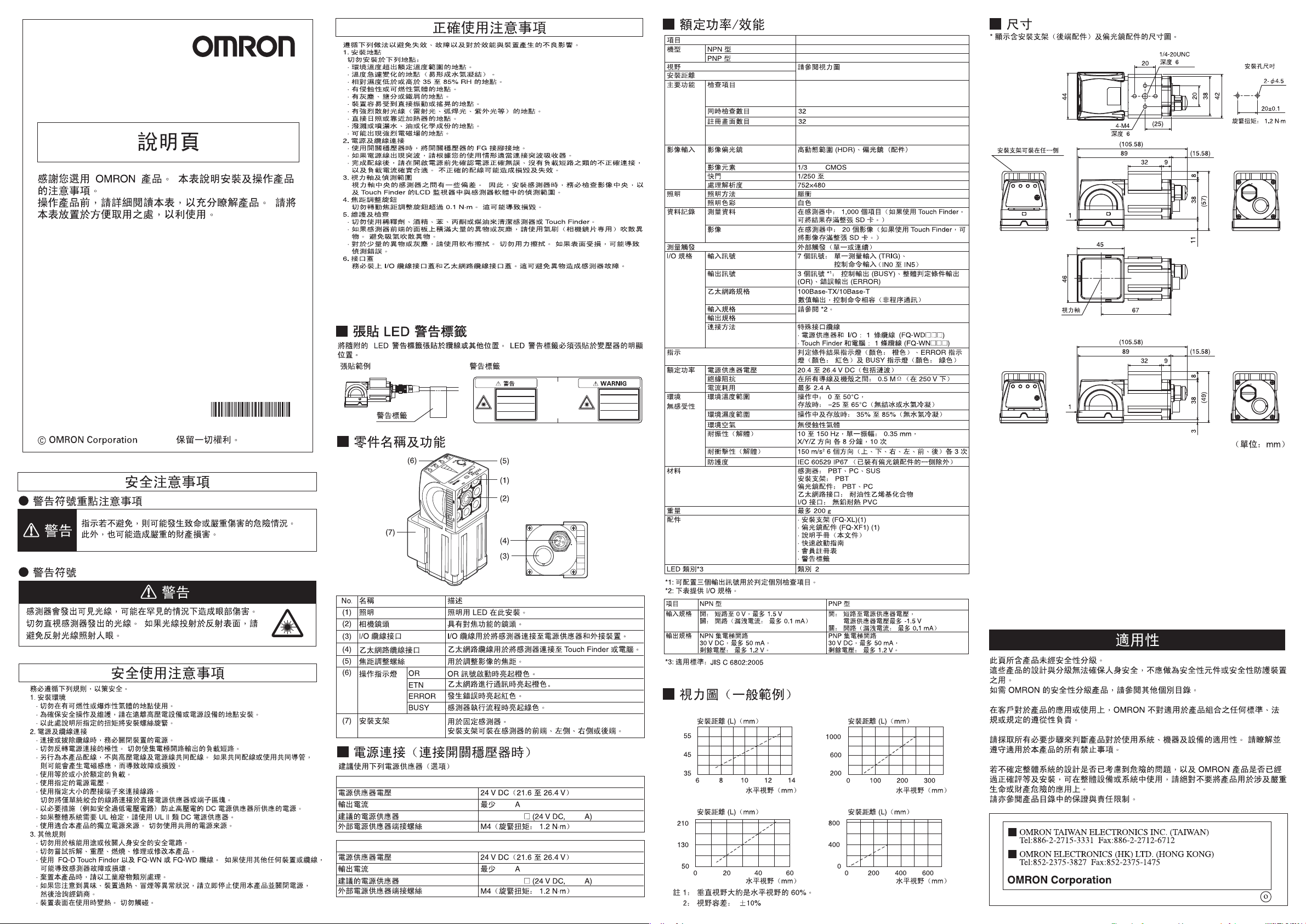
■外形寸法図
*取付金具(背面取付)、偏光フィルタアタッチメントありの寸法図を示す。
形FQ-CR2□010F-M/FQ-CR2□050F-M
44
4-M4
深さ6
取付金具は各側面に取付可能
1
46
光軸
(105.58)
89
45
1/4-20UNC
深さ6
20
203842
(25)
(15.58)
9
32
8
38
11
67
取付穴加工寸法
締付けトルク:1.2N・m
(57)
形FQ-CR2□100F-M/FQ-CR2□100N-M
(105.58)
89
32
1
(15.58)
9
8
(49)
383
(単位:mm)
ご使用に際してのご承諾事項
①安全を確保する目的で直接的または間接的に人体を検出する用途に、本製品を使用
しないでください。同用途には、当社センサカタログに掲載している安全センサをご使用
くださ い 。
②下記用途に使用される場合、当社営業担当者までご相談のうえ仕様書などによりご確
認いただくとともに、定格・性能に対し余裕を持った使い方や、万一故障があっても危
険を最小にする安全回路などの安全対策を講じてください。
a)屋外の用途、潜在的な化学的汚染あるいは電気的妨害を被る用途
またはカタログ、取扱説明書等に記載のない条件や環境での使用
b)原子力制御設備、焼却設備、鉄道・航空・車両設備、医用機械、娯楽機械、
安全装置、および行政機関や個別業界の規制に従う設備
c)人命や財産に危険が及びうるシステム・機械・装置
d)ガス、水道、電気の供給システムや24時間連続運転システムなどの
高い信頼性が必要な設備
e)その他、上記a)〜d)に準ずる、高度な安全性が必要とされる用途
*上記は適合用途の条件の一部です。当社のベスト、総合カタログ・データシート等最新版
のカタログ、マニュアルに記載の保証・免責事項の内容をよく読んでご使用ください。
●お問い合わせ先
カ ス タ マ サ ポ ート セ ン タ
フリーコール
携帯電話・PHSなどではご利用いただけませんので、その場合は下記電話番号へおかけください。
電話055-982-5015(通話料がかかります)
〔技術のお問い合わせ時間〕
■
営業時間:8:00〜21:00
■営業日:365日
■上記フリ−コ−ル以外のFAシステム機器の技術窓口:
電話055-977-6389(通話料がかかります)
〔営業のお問い合わせ時間〕
■
営業時間:9:00〜12:00/13:00〜17:30(土・日・祝祭日は休業)
■営業日:土・日・祝祭日/春期・夏期・年末年始休暇を除く
●FAXによるお問い合わせは下記をご利用ください。
カスタマサポートセンタ お客様相談室 FAX055-982-5051
●その他のお問い合わせ先
納期・価格・修理・サンプル・仕様書は貴社のお取引先、
または貴社担当オムロン営業員にご相談ください。
q
B
2009年10月
インダストリアルオートメーションビジネスカンパニー
0120-919-066
2-φ4.5
20±0.1
Page 2
Model
FQ-CR2
Fixed Mount 2D Code Reader
INSTRUCTION SHEET
Thank you for selecting OMRON product. This sheet primarily describes precautions required in installing and
operating the product.
Before operating the product, read the sheet thoroughly to
acquire sufficient knowledge of the product. For your convenience, keep the sheet at your disposal.
TRACEABILITY INFORMATION:
Representative in EU:
Omron Europe B.V.
Wegalaan 67-69
2132 JD Hoofddorp,
The Netherlands
The following notice applies only to products that carry the CE mark:
Notice:
This is a class A product. In residential areas it may cause radio
interference, in which case the user may be required to take adequate
measures to reduce interference.
OMRON Corporation All Rights Reserved.
©
SAFETY PRECAUTIONS
●Keys to Warning Symbols
WARNING
●Warning Symbols
The Sensor emits visible light which may on rare occasions
have a harmful effect on the eyes. Do not look directly at the
light emitted by the sensor. If the light projects onto a reflective
surface, prevent the reflected light from entering a person's
eyes.
Precautions for Safe Use
Always follow the rules below to ensure safety.
1. Installation environment
· Do not use in a location where there is ammable or explosive gas.
· To ensure safe operation and maintenance, install away from high-voltage equipment and
power equipment.
· Tighten the mounting screws to the torque specied in these instructions.
2. Power and cable connections
· Always turn off the power of the unit before connecting or disconnecting cables.
· Do not reverse the polarity of the power connection. Do not short the load of the open
collector output.
·
Wire this product separately from the wiring of high-voltage wires and power wires. If wired
together or in the same conduit, induction may occur and cause malfunctioning or damage.
· Use a load that is equal to or less than the rating.
· Use the specied power voltage.
· Use the specied size of crimp terminals for wiring connections. Do not connect wires that
have been simply twisted together directly to the power supply or terminal block.
· Supply power from a DC power supply for which measures have been applied to prevent
high voltages (e.g., a safety extra low voltage circuit).
· If UL certication is required for the overall system, use a UL Class II DC power supply.
· Use an independent power source for this product. Do not use a shared power source.
3. Other Rules
· Do not use in safety circuits for atomic energy or that are critical for human life.
· Do not attempt to disassemble, deform by pressure, incinerate, repair, or modify this product.
· Use the FQ-D Touch Finder and the FQ-WN or FQ-WD Cable. Sensor malfunction or
damage may occur if any other devices or cables are used.
· When disposing of the product, treat as industrial waste.
· If you notice an abnormal condition such as a strange odor, extreme heating of the unit, or
smoke, immediately stop using the product, turn off the power, and consult your dealer.
· The device surface becomes hot during use. Do not touch.
Manufacturer:
Omron Corporation,
Shiokoji Horikawa, Shimogyo-ku,
Kyoto 600-8530 JAPAN
Ayabe Factory
3-2 Narutani, Nakayama-cho,
Ayabe-shi, Kyoto 623-0105 JAPAN
2011
Indicates a potentially hazardous situation which, if
not avoided, could result in death or serious injury.
Additionally, there may be severe property damage.
WARNING
Precautions for Correct Use
Observe the following to prevent failure, malfunctioning, and adverse effects on performance and
the device.
1. Installation site
· Do not install in the following locations:
· Locations where the ambient temperature exceeds the rated temperature range.
· Locations subject to sudden temperature changes (where condensation will form).
· Locations where the relative humidity is below or above 35 to 85% RH.
· Locations where there are corrosive or ammable gases.
· Locations where there is dust, salt, or iron powder.
· Locations where the device will be subject to direct vibration or shock.
· Locations where there is strong scattered light (laser light, arc welding light, ultraviolet light, etc.)
· Locations exposed to direct sunlight or next to a heater.
· Locations where there is splashing or spraying of water, oil, or chemicals.
· Locations where there is a strong electrical or magnetic eld.
2. Power and cable connections
· When using a switching regulator, ground the FG pin of the switching regulator.
If there are surges on your power line, connect a surge absorber as appropriate for your conditions of use.
·
· Before turning on the power after the wiring is completed, verify that the power is correct, that
there are no incorrect connections such as a shorted load circuit, and that the load current is
suitable. Incorrect wiring may cause damage and failures.
3. Optical axis and detection range
There is a certain amount of deviation among sensors in the center of the optical axis. For this
reason, when installing the sensor, be sure to check the center of the image and the detection
range in the LCD monitor of the Touch Finder and in the sensor software.
4. Focus adjustment knob
Do not turn the focus adjustment knob to higher than 0.1 N·m. This may cause damage.
5. Maintenance and inspection
· Do not use thinner, alcohol, benzene, acetone, or kerosene to clean the sensor or Touch Finder.
·
If considerable foreign matter or dust collects on the panel on the front of the senor, use a blower
brush (for camera lenses) to blow off the foreign matter. Avoid blowing it off with your breath.
· For a small amount of foreign matter or dust, gently wipe with a soft cloth. Do not wipe hard.
If the surface is damaged, false detection may result.
6. Connector cover
Always attach the covers of I/O cable connector and Ethernet cable connector.
This prevents extraneous material from making malfunction of sensor.
7. Defective pixel
· It is neither a defect of the product nor a breakdown though two or more defective pixels might
be included in this product by the specication of CMOS image sensor.
8. Installation of camera
· In the environment with high humidity and intense temperature change, the inside of a front
plate might uncommonly become cloudy.
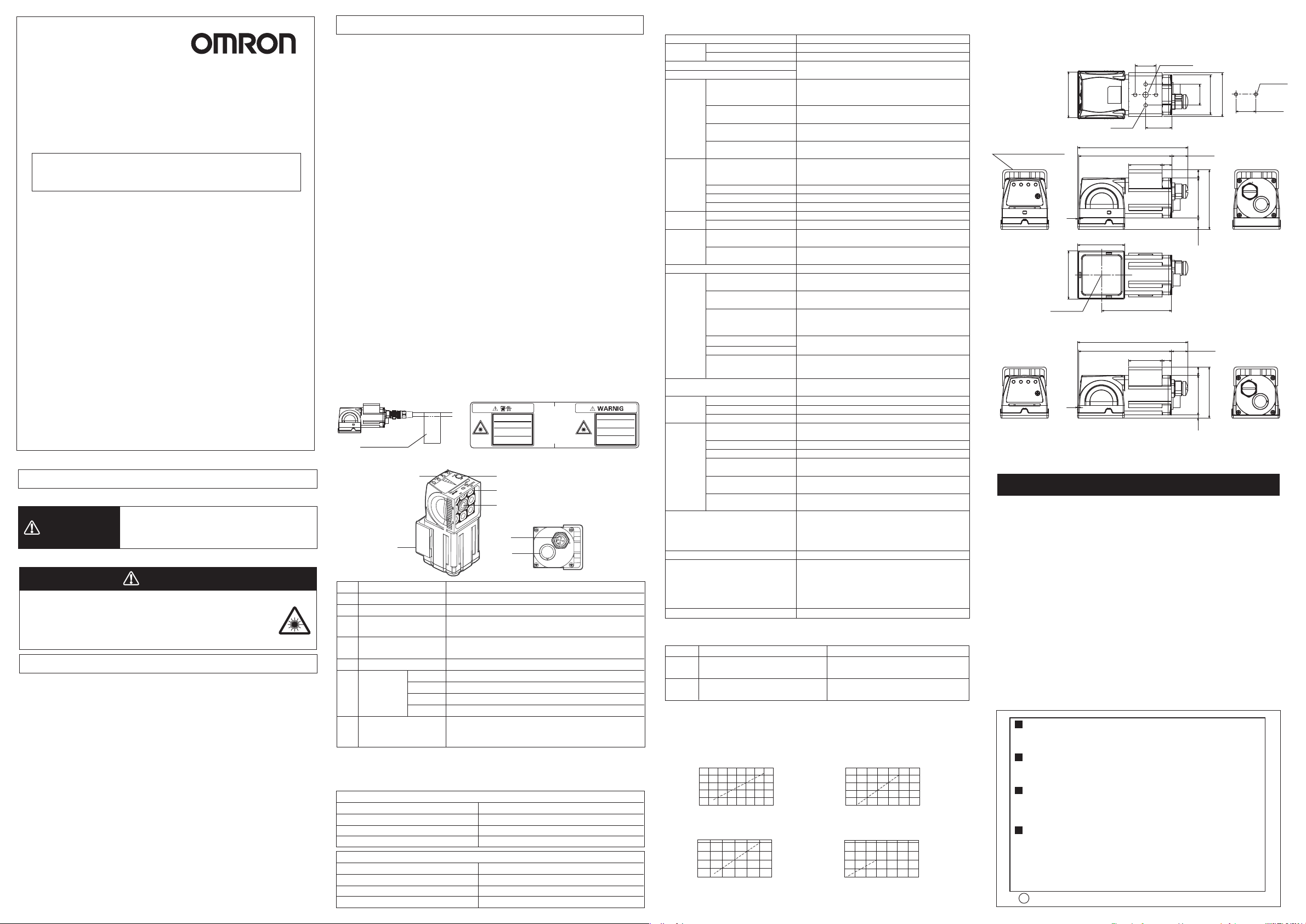
■ Attaching the LED Warning Label
Attach the enclosed LED warning label to the cable or other location. The LED warning
label must be attached to a location that is readily visible from the Sensor.
Attachment Example Warning Label
LED放射
ビームをのぞき込まないこと
Max.65mW
400-700nm
ク ラス 2 LE D 製 品
Warning Label
JIS C 6802:2005
■ Part Names and Functions
(7)
(1)
Lighting
(2)
Camera lens
I/O Cable connector
(3)
(4)
Ethernet cable
connector
(5)
Focus adjustment screw
(6)
Operation
indicators
(7)
Mounting Bracket
(6)
OR
ETN
ERROR
BUSY
DescriptionNameNo.
LEDs for illumination are mounted here.
Lens with a focus feature.
An I/O Cable is used to connect the Sensor to the power
supply and external devices.
An Ethernet cable is used to connect the Sensor to the
Touch Finder or a computer.
Used to adjust the focus of the image.
Lights orange when the OR signal turns ON.
Lights orange during communication by Ethernet.
Lights red when an error occurs.
Lights green when the Sensor is executing a process.
Used to secure the Sensor in place.
The Mounting Bracket can be attached to the front, left
side, right side, or back of the Sensor.
(5)
(1)
(2)
(4)
(3)
■ Power connection
(when a switching regulator is connected)
The following power supply is recommended (option)
FQ-CR2□010F-M/FQ-CR2□050F-M
Power supply voltage
Output current
Recommended Power Supply
External power supply terminal screws
FQ-CR2□100F-M/FQ-CR2□100N-M
Power supply voltage
Output current
Recommended Power Supply
External power supply terminal screws
24 VDC (21.6 to 26.4 V)
1.25 A min.
S8VS-030024□ (24 VDC, 1.25 A)
M4 (tightening torque: 1.2 N・m)
24 VDC (21.6 to 26.4 V)
2.5 A min.
S8VS-060024□ (24 VDC, 2.5 A)
M4 (tightening torque: 1.2 N・m)
LED RADIATION
DO NOT STARE
INTO BEAM
Max.65mW
400-700nm
CLASS 2 LED PRODUCT
JIS C 6802:2005
■
Ratings/Performance
Item
Model NPN
Field of view
Installation distance
Main
functions
Image
input
Lighting
logging
Measurement trigger
I/O
specifications
Indications
Ratings
Environmental
immunity
Materials
Weight
Accessories
LED class*
*1: The three output signals can be allocated for the judgments of individual inspection items.
*2: The following table gives the I/O specifications.
Item
Input
specifications
Output
specifications
*3: Applicable standards: JIS C 6802:2005
PNP
Inspection items
Number of simultaneous
inspections
Number of registered
scenes
Retry function
Image filter
Image elements
Shutter
Processing resolution
Lighting method
Lighting color
Measurement dataData
Images
Input signals
Output signals
Ethernet specifications
Input specifications
Output specifications
Connection method
Power supply voltage
Insulation resistance
Current consumption
Ambient temperature range
Ambient humidity range
Ambient atmosphere
Vibration resistance
(destruction)
Shock resistance
(destruction)
Degree of protection
3
NPN
ON: Shorted to 0 V, or 1.5 V max.
OFF: Open (leakage current: 0.1 mA max.)
NPN open collector
30 VDC, 50 mA max., residual voltage: 1.2
V max.
Fixed Mount 2D Code Reader
FQ-CR20□□□□-M
FQ-CR25□□□□-M
Refer to the optical diagram
2D code (compatible code: Data Matrix ECC200 from 10
x 10 to 64 x 64, 8 x 18 to 16 x 48, QR Code model 1 and
2 from 21 x 21 to 57 x 57 (version 1 to 10)
32
32
Simple retry, brightness fluctuation retry, scene switch
retry, level trigger retry
High dynamic range (HDR) polarizing filter
(attachment), and smoothing, expansion, reduction,
median
1/3-inch Monochrome CMOS
1/250 to 1/32258
752×480
Pulse
White
In Sensor: 1,000 items (If a Touch Finder is used,
results can be saved up to the capacity of an SD card.)
In Sensor: 20 images (If a Touch Finder is used, images
can be saved up to the capacity of an SD card.)
External trigger (single or continuous)
7 signals: Single measurement input (TRIG),
Control Command Input (IN0 to IN5)
3 signals *1: Control output (BUSY), overall judgment
output (OR), error output (ERROR)
100Base-TX/10Base-T
Numerical output, control command compatible
(Non-procedural communications)
Refer to *2.
Special connector cables
-
Power supply and I/O: 1cable (FQ-WD□□□)
-
Touch Finder and computer: 1cable (FQ-WN□□□)
Judgment results indicator (color: orange), ERROR
indicator (color: red), and BUSY indicator (color: green)
20.4 to 26.4 VDC (including ripple)
Between all lead wires and case: 0.5 MΩ (at 250 V)
2.4 A max.
Operating: 0 to 50°C, storage: -25 to 65°C (no icing or
condensation)
Operating and storage: 35% to 85% (with no condensation)
No corrosive gas
10 to 150 Hz, single amplitude: 0.35 mm, X/Y/Z
directions 8 min each, 10 times
2
150 m/s
3 times each in 6 direction (up, down, right,
left, forward, and backward)
IEC 60529 IP67 (except when the polarizing filter
attachment is attached)
Sensor: PBT, PC, SUS
Mounting Bracket: PBT
Polarizing Filter Attachment: PBT, PC
Ethernet connector: Oil-resistance vinyl compound
I/O connector: Lead-free heat-resistant PVC
200 g max.
· Mounting Bracket (FQ-XL)(1)
· Polarizing Filter Attachment (FQ-XF1) (1)
· Instruction Manual (this document)
· Quick Startup Guide
· Member Registration Sheet
· Warning Label
Class 2
PNP
ON: Shorted to power supply voltage, or power
supply voltage -1.5 V max.
OFF: Open (leakage current: 0.1 mA max.)
PNP open collector
30 VDC, 50 mA max., residual voltage: 1.2 V
max.
■ Optical diagram (typical example)
· FQ-CR2□010F-M · FQ-CR2□100F-M
Installation distance (L) (mm)
55
45
35
6 8 10 12 14
· FQ-CR2
210
130
Note 1: Vertical eld of view will be approximately 60% of the horizontal eld of view.
Horizontal field of view (mm)
□
050F-M · FQ-CR2□100N-M
Installation distance (L) (mm)
50
0 20 40 60
Horizontal field of view (mm)
2: Field of view tolerance: ±10%
Installation distance (L) (mm)
1000
600
200
0 100 200 300
Horizontal field of view (mm)
Installation distance (L) (mm)
800
400
0
0 200 400 600
Horizontal field of view (mm)
■ Dimensions
* Dimension diagram with mounting bracket (rear-side attachment) and polarizing filter
attachment is shown.
FQ-CR2□010F-M/FQ-CR2□050F-M
44
4-M4
The mounting bracket can be
attached to any side
1
46
Optical axis
FQ-CR2□100F-M/FQ-CR2□100N-M
1
Depth 6
(105.58)
89
45
(105.58)
89
Suitability for Use
THE PRODUCTS CONTAINED IN THIS SHEET ARE NOT SAFETY RATED.
THEY ARE NOT DESIGNED OR RATED FOR ENSURING SAFETY OF
PERSONS, AND SHOULD NOT BE RELIED UPON AS A SAFETY
COMPONENT OR PROTECTIVE DEVICE FOR SUCH PURPOSES.
Please refer to separate catalogs for OMRON's safety rated products.
OMRON shall not be responsible for conformity with any standards, codes, or
regulations that apply to the combination of the products in the customer's
application or use of the product.
Take all necessary steps to determine the suitability of the product for the
systems, machines, and equipment with which it will be used.
Know and observe all prohibitions of use applicable to this product.
NEVER USE THE PRODUCTS FOR AN APPLICATION INVOLVING
SERIOUS RISK TO LIFE OR PROPERTY WITHOUT ENSURING THAT THE
SYSTEM AS A WHOLE HAS BEEN DESIGNED TO ADDRESS THE RISKS,
AND THAT THE OMRON PRODUCT IS PROPERLY RATED AND
INSTALLED FOR THE INTENDED USE WITHIN THE OVERALL
EQUIPMENT OR SYSTEM.
See also Product catalog for Warranty and Limitation of Liability.
EUROPE
OMRON EUROPE B.V. Sensor Business Unit
Carl-Benz Str.4, D-71154 Nufringen Germany
Phone:49-7032-811-0 Fax: 49-7032-811-199
NORTH AMERICA
OMRON ELECTRONICS LLC
One Commerce Drive Schaumburg,IL 60173-5302 U.S.A.
Phone:1-847-843-7900 Fax : 1-847-843-7787
ASIA-PACIFIC
OMRON ASIA PACIFIC PTE. LTD.
No. 438A Alexandra Road #05-05-08(Lobby 2),
Alexandra Technopark, Singapore 119967
Phone : 65-6835-3011 Fax :65-6835-2711
CHINA
OMRON(CHINA) CO., LTD.
Room 2211, Bank of China Tower,
200 Yin Cheng Zhong Road,
PuDong New Area, Shanghai, 200120, China
Phone : 86-21-5037-2222 Fax :86-21-5037-2200
OMRON Corporation
o
OCT, 2009
D
1/4-20UNC
Depth 6
20
203842
(25)
32
67
32
(15.58)
9
8
38
11
(15.58)
9
8
383
(57)
(49)
Mounting hole
dimensions
2-4.5Dia.
20±0.1
Tightening
torque: 1.2 N·m
(Unit: mm)
Page 3
讀碼器相容機型
FQ-CR20□□□□-M
FQ-CR25□□□□-M
FFQ-CR2□010F-M/FQ-CR2□050F-M
FQ-CR2
固定型2維讀碼器
* 2 1 9 1 0 0 7 - 9 A *
7. 關於像素缺失
·本產品在CMOS影像感測器(光電元件)之規格上,有時會存在多個像素缺失,並非產
品缺陷或故障所致。
8. 關於相機設置
·在高溫且溫度急劇變化的環境下,前板內部可能會發生罕見的模糊不清的現象。
LED放射
ビームをのぞき込まないこと
Max.65mW
400-700nm
ク ラス 2 LE D 製 品
JIS C 6802:2005
LED RADIATION
DO NOT STARE
INTO BEAM
Max.65mW
400-700nm
CLASS 2 LED PRODUCT
JIS C 6802:2005
重試功能
2維碼(相容碼 Data Matrix ECC200 10×10~64×64
、8×18~16×48、QR Code 模型1,2 21×21~57×57
(版本1~10))
單純重試、亮度變動重試、註冊畫面切換重試、準位觸
發重試
平滑化、膨脹、壓縮、中間值
單色
1/32258
FQ-CR2□100F-M/FQ-CR2□100N-M
2011
②
· FQ-CR2
□
· FQ-CR2□010F-M
100F-M
FQ-CR2□010F-M/FQ-CR2□050F-M
FQ-CR2□100F-M/FQ-CR2□100N-M
1.25
S8VS-030024
2.5
S8VS-060024
1.25
2.5
· FQ-CR2
□
050F-M · FQ-CR2□100N-M
Page 4

固定型2维读码器
FQ-CR20□□□□-M
FQ-CR25□□□□-M
FQ-CR2□010F-M/FQ-CR2□050F-M
FQ-CR2
固定型2维读码器
7. 关于像素缺失
·本产品在CMOS图像传感器(光电元件)的规格上,有时会存在多个像素缺失,并非产
品缺陷或故障所致。
8. 关于相机设置
·在高温且温度急剧变化的环境下,前板内部可能会发生罕见的模糊不清的现象。
LED放射
ビームをのぞき込まないこと
Max.65mW
400-700nm
ク ラス 2 LE D 製 品
JIS C 6802:2005
LED RADIATION
DO NOT STARE
INTO BEAM
Max.65mW
400-700nm
CLASS 2 LED PRODUCT
JIS C 6802:2005
重试功能
2维码(适用码 Data Matrix ECC200 10×10~64×64
、8×18~16×48、QR Code 型号1,2 21×21~57×57
(版本1~10))
单纯重试、亮度变动重试、注册场景切换重试、条件触
发重试
平滑化、膨胀、压缩、中值
黑白
1/32258
FQ-CR2□100F-M/FQ-CR2□100N-M
2011
· FQ-CR2□010F-M
· FQ-CR2
□
100F-M
FQ-CR2□010F-M/FQ-CR2□050F-M
FQ-CR2□100F-M/FQ-CR2□100N-M
1.25
S8VS-030024
2.5
S8VS-060024
1.25
2.5
· FQ-CR2
□
050F-M · FQ-CR2□100N-M
Page 5

Fester 2D Strichcodeleser
FQ-CR20□□□□-M
FQ-CR25□□□□-M
FQ-CR2
Fester 2D Strichcodeleser
7. Pixelfehler
・ Dieses Produkt ist ein CMOS-Bildsensor (Lichtempfangselement) laut den Spezikationen. Es
kann Pixelfehler haben, aber dies stellt keine Funktionsstörung und keinen Produktmangel dar.
8. Kamerainstallation
・ Bei starken Temperaturschwankungen und bei hohen Temperaturen kann die Frontplatte in
seltenen Fällen anlaufen.
Wiederholungsfunktion
2D Code (Kompatible Codes: Data Matrix ECC200
10×10〜64×64, 8×18〜16×48, QR Code-Model 1,2
21×21〜57×57 (Versionen 1〜10))
Einfache Wiederholung, Wiederholung für Helligkeitsflunktuation,
Wiederholung für Scenenwechsel, Wiederholung für Levelauslöser
Glätten, Strecken, Ver kürzen, Median
Monochrome-CMOS
1/32258
FQ-CR2□010F-M/FQ-CR2□050F-M
LED放射
ビームをのぞき込まないこと
Max.65mW
400-700nm
ク ラス 2 LE D 製 品
JIS C 6802:2005
LED RADIATION
DO NOT STARE
INTO BEAM
Max.65mW
400-700nm
CLASS 2 LED PRODUCT
JIS C 6802:2005
2011
* 2 1 9 1 0 0 7 - 9 A *
③
FQ-CR2□100F-M/FQ-CR2□100N-M
FQ-CR2□010F-M/FQ-CR2□050F-M
FQ-CR2□100F-M/FQ-CR2□100N-M
1.25 A
S8VS-030024
2.5 A
S8VS-060024
· FQ-CR2□010F-M · FQ-CR2□100F-M
1.25 A
· FQ-CR2□050F-M · FQ-CR2□100N-M
2.5 A
Page 6

Lecteur Code QR Fixe
FQ-CR20□□□□-M
FQ-CR25□□□□-M
FQ-CR2
Lecteur Code QR Fixe
7. Concernant les pixels défectueux :
・ En raison des spécications du capteur d’image CMOS (éléments d’image), il peut y avoir des
pixels défectueux : il ne s’agit pas d’un défaut ou d’une anomalie de ce produit.
8. Installation de la caméra :
・ L’intérieur du panneau avant peut s’embuer à cause d’une température élevée et/ou d’un
changement brusque de température.
Fonction de relance
Code QR (Code correspondant Data Matrix ECC200
10×10 à 64×64, 8×18 à 16×48, code QR Model 1,2
21×21 à 57×57 (Version 1 à 10) )
Relance simple, relance avec changement de luminosité, relance
avec changement de lieu, relance avec declencheur de niveau
lissage, dilatation, contraction, median
Monochrome
1/32258
FQ-CR2□010F-M/FQ-CR2□050F-M
LED放射
ビームをのぞき込まないこと
Max.65mW
400-700nm
ク ラス 2 LE D 製 品
JIS C 6802:2005
LED RADIATION
DO NOT STARE
INTO BEAM
Max.65mW
400-700nm
CLASS 2 LED PRODUCT
JIS C 6802:2005
2011
FQ-CR2□100F-M/FQ-CR2□100N-M
· FQ-CR2□010F-M · FQ-CR2□100F-M
FQ-CR2□010F-M/FQ-CR2□050F-M
FQ-CR2□100F-M/FQ-CR2□100N-M
1.25 A
S8VS-030024
2.5 A
S8VS-060024
1.25 A
2.5 A
□
050F-M · FQ-CR2□100N-M
· FQ-CR2
Page 7

Lettore Codice 2D Fisso
FQ-CR20□□□□-M
FQ-CR25□□□□-M
FQ-CR2
Lettore Codice 2D Fisso
7. La presenza di più pixel danneggiati, a seconda della progettazione del sensore d'imagine
CMOS (elemento ricevente della luce) del prodotto, non costituiscono un danno od un
guasto per il prodotto stesso,
8. Se la camera viene posizionata in un ambiente soggetto ad improvvisi aumenti e sbalzi di
temperatura, la parte interna della piastra frontale potrebbe appannarsi.
Funzione riprova
Código 2D (Códigos compatibles: Data Matrix ECC200
10×10〜64×64, 8×18〜16×48, Código QR modelo 1,2
21×21〜57×57 (versiones 1〜10))
Reintento simple, reintento de fluctuación de luminosidad, reintento
de cambio de escena, reintento de nivel del disparador.
Suavización, dilatación, contracción, mediana.
Monocromo
1/32258
FQ-CR2□010F-M/FQ-CR2□050F-M
LED放射
ビームをのぞき込まないこと
Max.65mW
400-700nm
ク ラス 2 LE D 製 品
JIS C 6802:2005
LED RADIATION
DO NOT STARE
INTO BEAM
Max.65mW
400-700nm
CLASS 2 LED PRODUCT
JIS C 6802:2005
2011
* 2 1 9 1 0 0 7 - 9 A *
④
· FQ-CR2□010F-M · FQ-CR2□100F-M
FQ-CR2□100F-M/FQ-CR2□100N-M
FQ-CR2□010F-M/FQ-CR2□050F-M
FQ-CR2□100F-M/FQ-CR2□100N-M
1.25 A
S8VS-030024
2.5 A
S8VS-060024
1.25 A
2.5 A
· FQ-CR2□050F-M · FQ-CR2□100N-M
Page 8

Lector Código de Barra 2D Fijo
FQ-CR20□□□□-M
FQ-CR25□□□□-M
FQ-CR2
Lector Código de Barra 2D Fijo
7. Acerca de los defectos de los píxeles.
・ Este artículo dispone de un sensor que detecta la luz (elemento receptor de luz) basado en la
tecnología CMOS por lo que hay veces que presenta múltiples defectos de los píxeles pero
esto no signica que el artículo sea defectuoso o que presente una avería.
8. Acerca del lugar de colocación de la cámara.
・ Si se coloca en un entorno en donde las temperaturas son altas y en donde haya grandes
variaciones térmicas, existe, en raras ocasiones, el riesgo de que la parte interior de la placa
frontal se empañe.
Función de reintento
Código 2D (Códigos compatibles: Data Matrix ECC200
10×10〜64×64, 8×18〜16×48, Código QR modelo 1,2
21×21〜57×57 (versiones 1〜10))
Reintento simple, reintento de fluctuación de luminosidad, reintento
de cambio de escena, reintento de nivel del disparador.
Suavización, dilatación, contracción, mediana.
Monocromo
1/32258
FQ-CR2□010F-M/FQ-CR2□050F-M
LED放射
ビームをのぞき込まないこと
Max.65mW
400-700nm
ク ラス 2 LE D 製 品
JIS C 6802:2005
LED RADIATION
DO NOT STARE
INTO BEAM
Max.65mW
400-700nm
CLASS 2 LED PRODUCT
JIS C 6802:2005
2011
FQ-CR2□100F-M/FQ-CR2□100N-M
· FQ-CR2□010F-M · FQ-CR2□100F-M
FQ-CR2□010F-M/FQ-CR2□050F-M
FQ-CR2□100F-M/FQ-CR2□100N-M
1.25 A
S8VS-030024
2.5 A
S8VS-060024
1.25 A
2.5 A
· FQ-CR2□050F-M · FQ-CR2□100N-M
Page 9

고정식 2차원코드리더
FQ-CR20□□□□-M
FQ-CR25□□□□-M
FQ-CR2
고정식 2차원코드리더
7. 화소결함에 관해
·본 제품은 CMOS 이미지 센서(수광소자)의 사양 상 화소결함이 있을 수 있으나,
제품의 결함이나 고장이 아닙니다.
8. 카메라 설치에 관해
·고온의 온도변화가 심한 환경에서는, 전면 플레이트의 내부가 간혹 흐려지는 경우가
있습니다.
리트라이 기능
2차원코드(대응코드 Data Matrix ECC200 10×10~
64×64、8×18~16×48、QR Code 모델1,2 21×21
~57×57(버전1~10))
단순 리트라이, 밝기변동 리트라이, 신 절환 리트라이,
레벨트리거 리트라이
평활화, 팽창, 수축, 메디안
흑백
1/32258
FQ-CR2□010F-M/FQ-CR2□050F-M
LED放射
ビームをのぞき込まないこと
Max.65mW
400-700nm
ク ラス 2 LE D 製 品
JIS C 6802:2005
LED RADIATION
DO NOT STARE
INTO BEAM
Max.65mW
400-700nm
CLASS 2 LED PRODUCT
JIS C 6802:2005
2011
* 2 1 9 1 0 0 7 - 9 A *
⑤
FQ-CR2□100F-M/FQ-CR2□100N-M
· FQ-CR2□010F-M · FQ-CR2□100F-M
FQ-CR2□010F-M/FQ-CR2□050F-M
FQ-CR2□100F-M/FQ-CR2□100N-M
1.25 A
S8VS-030024
2.5 A
S8VS-060024
1.25 A
2.5 A
· FQ-CR2
□
050F-M · FQ-CR2□100N-M
 Loading...