

Page 1

Fixed Mount 2D Code Reader
FQ-CR2
User's Manual
Cat. No. Z316-E1-01
Page 2

Introduction
Thank you for purchasing the FQ-CR2.
This manual provides information regarding functions, perfor mance and operating methods that
are required for using the FQ-CR2.
When using the FQ-CR2, be sure to observe the following:
• The FQ-CR2 must be operated by personnel knowledgeable in electrical engineering.
• To ensure correct use, please read this manual thoroughly to deepen your understanding of the
product.
• Please keep this manual in a safe place so that it can be referred to whenever necessary.
Page 3

APPLICA TION CONSIDERA TIONS
(Please Read)
1
User's Manual
Introduction
Installation and Connections
Taking Images
Setting Up Inspections
Testing and Saving Settings
Operation
1
2
3
4
5
6
Fixed Mount 2D Code Reader
FQ-CR2
Convenient Functions
Communications with External Devices
Troubleshooting
Appendices
7
8
9
10
Page 4

READ AND UNDERSTAND THIS DOCUMENT
Please read and understand this document before using the products. Please consult your OMRON
representative if you have any questions or comments.
WARRANTY
OMRON’s exclusive warranty is that the products are free from defects in materials and workmanship for a
period of one year (or other period if specified) from date of sale by OMRON.
OMRON MAKES NO WARRANTY OR REPRESENTATION, EXPRESS OR IMPLIED, REGARDIN G NONINFRINGEMENT, MERCHANTABILITY, OR FITNESS FOR PARTICULAR PURPOSE OF THE PRODUCTS.
ANY BUYER OR USER ACKNOWLEDGES TH AT THE BUYER OR USER ALONE HAS DET ER MI NE D THAT
THE PRODUCTS WILL SUITABLY MEET THE REQUIREMENTS OF THEIR INTENDED USE. OMRON
DISCLAIMS ALL OTHER WARRANTIES, EXPRESS OR IMPLIED.
LIMITATIONS OF LIABILITY
OMRON SHALL NOT BE RESPONSIBLE FOR SPECIAL, INDIRECT, OR CONSEQUENTIAL DAMAGES,
LOSS OF PROFITS OR COMMERCIAL LOSS IN ANY WAY CONNECTED WITH THE PRODUCTS,
WHETHER SUCH CLAIM IS BASED ON CONTRACT, WARRANTY, NEGLIGENCE, OR STRICT LIABILITY.
In no event shall responsibility of OMRON for any act exceed the individual price of the product on which
liability is asserted.
IN NO EVENT SHALL OMRON BE RESPONSIBLE FOR WARRANTY, REPAIR, OR OTHER CLAIMS
REGARDING THE PRODUCTS UNLESS OMRON’S ANALYSIS CONFIRMS THAT THE PRODUCTS WERE
PROPERLY HANDLED, STORED, INSTALLED, AND MAINTAINED AND NOT SUBJECT TO
CONTAMINATION, ABUSE, MISUSE, OR INAPPROPRIATE MODIFICATION OR REPAIR.
SUITABILITY FOR USE
THE PRODUCTS CONTAINED IN THIS DOCUMENT ARE NOT SAFETY RATED. THEY ARE NOT DESIGNED OR
RATED FOR ENSURING SAFETY OF PERSONS, AND SHOULD NOT BE RELIED UPON AS A SAFETY COMPONENT OR PROTECTIVE DEVICE FOR SUCH PURPOSES.
Please refer to separate catalogs for OMRON’s safety rated products.
OMRON shall not be responsible for conformity with any standards, codes, or regulations that apply to the
combination of products in the customer’s application or use of the pr oduct.
At the customer’s request, OMRON will provide applicable third party cert ification document s identif ying ratings
and limitations of use that apply to the products. This information by itself is not sufficient for a complete
determination of the suitability of the products in combination with the end product, machine, system, or other
application or use.
The following are some examples of applications for which particular attention must be given. This is not
intended to be an exhaustive list of all possible uses of the products, nor is it intended to imply that the uses
listed may be suitable for the products:
• Outdoor use, uses involving potential chemical contamination or electrical interference, or conditions or
uses not described in this document.
2
FQ-CR2 User’s Manual
Page 5

• Nuclear energy control systems, combustion systems, railroad systems, aviation systems, medical
equipment, amusement machines, vehicles, safet y equipment, and in sta llat ions subject to sep arat e industr y
or government regulations.
• Systems, machines, and equipment that could present a risk to life or property.
Please know and observe all prohibitions of use applicable to the products.
NEVER USE THE PRODUCTS FOR AN APPLICATION INVOLVING SERIOUS RISK TO LIFE OR
PROPERTY WITHOUT ENSURING THAT THE SYSTEM AS A WHOLE HAS BEEN DESIGNED TO
ADDRESS THE RISKS, AND THAT THE OMRON PRODUCT IS PROPERLY RATED AND INSTALLE D FOR
THE INTENDED USE WITHIN THE OVERALL EQUIPMENT OR SYSTEM.
PERFORMANCE DA TA
Performance data given in this document is provi ded as a guide f or the us er in determi nin g suitability and does
not constitute a warranty. It may represent the result of OMRON’s test conditions, and the users must correlate
it to actual application requirements. Actual performance is subject to the OMRON Warranty and Limitations of
Liability.
CHANGE IN SPECIFICATIONS
Product specifications and accessories may be changed at any time based on improvements and other
reasons.
It is our practice to change model numbers when published ra tings or features are changed, or when signifi cant
construction changes are made. However, some specifications of the product may be changed without any
notice. When in doubt, special model numbers may be assigned to fix or establish key specifications for your
application on your request. Please consult with your OMRON representative at any time to confirm actual
specifications of purchased products.
DIMENSIONS AND WEIGHTS
Dimensions and weights are nominal and are not to be used for manufacturing purposes, even when
tolerances are shown.
ERRORS AND OMISSIONS
The information in this document has been carefully checked and is believed to be accurate; however, no
responsibility is assumed for clerical, typographical, or proofreading errors, or omissions.
PROGRAMMABLE PRODUCTS
OMRON shall not be responsible for the user’s programming of a programmable product, or any consequen ce
thereof.
COPYRIGHT AND COPY PERMISSION
This document shall not be copied for sales or promotions without permission.
This document is protected by copyright and is intended solely for use in conjunction with the product. Please
notify us before copying or reproducing this document in any manner, for any other purpose. If copying or
transmitting this document to another, please copy or transmit it in its entirety.
FQ-CR2 User’s Manual
3
Page 6
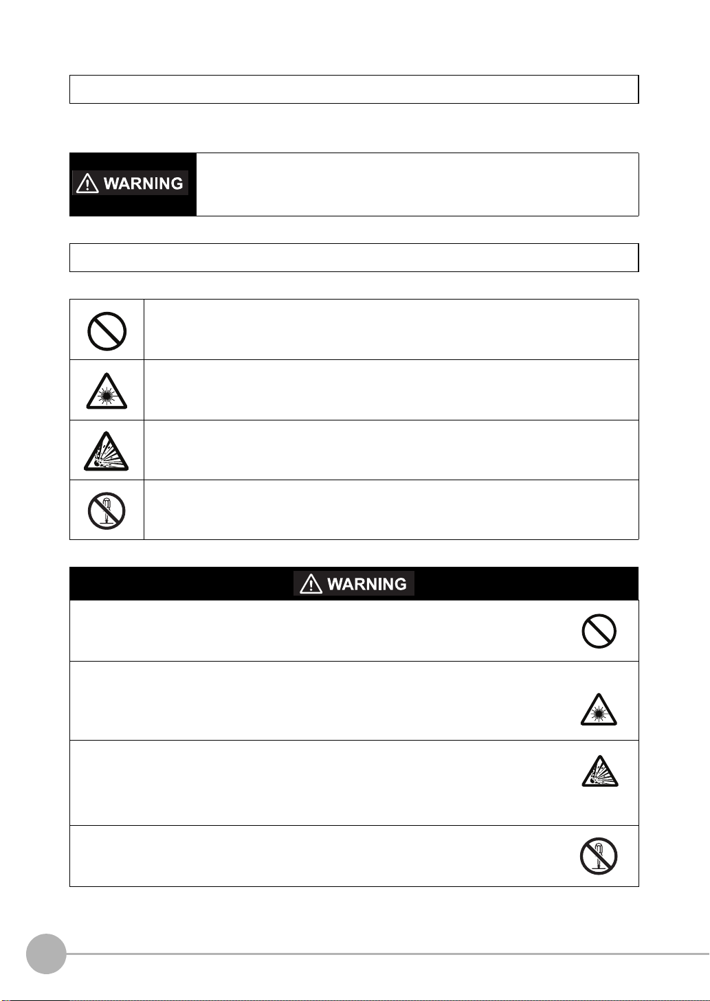
Meanings of Signal Words
The following signal words are used in this manual.
Indicates a potentially hazardous situation which, if not avoided, will result in minor or
moderate injury, or may result in serious injury or death. Additionally there may be
significant property damage.
Meanings of Alert Symbols
The following alert symbols are used in this manual
Indicates general prohibitions for which there is no specific symbol.
Indicates the possibility of laser radiation.
Indicates the possibility of explosion under speci fic conditions.
Indicates prohibition when there is a risk of minor injury from electrical shock or other
source if the product is disassembled.
This product is not designed or rated for ensuring safety of persons.
Do not use it for such purposes.
The Sensor emits visible light, which may adversely affect the eyes in rare instances.
Do not look directly into the light emitted from the Sensor. When the subject is a specular
reflective object, protect your eyes from reflected light.
A lithium ion battery is built into the Touch Finder and may occasionally combust, explode, or
burn if not treated properly.
Dispose of the Touch Finder as industrial waste, and never disassemble, apply pressure that
would deform, heat to 100 °C or higher, or incinerate the Touch Finder.
High-voltage parts insid e; danger of electrical shock. Do not open the product cover.
4
FQ-CR2 User’s Manual
Page 7

Precautions for Safe Use
The following points are important to ensure safety, so make sure that they are strictly observed.
1. Installation Environment
• Do not use the product in environments where it can be exposed to inflammable/explosive gas.
• To secure the safety of operation and maintenance, do not install the product close to high-voltage devices
and power devices.
• Install the product in such a way that its ventila tion holes are not blocked.
• Tighten mounting screws at the torque specified in this manual.
2. Power Supply and Wiring
• The power supply voltage must be within the rated range (24 VDC ±10%), and an AC voltage must not be
used.
• Reverse connection of the power supply is not allowed. Do not short the load of the open collector output.
• The load must be within the rated range.
• High-voltage lines and power lines must be wired separately from this product. Wiring them together or
placing them in the same duct may cause induction, resulting i n malfunction or damage.
• Use the products within the power supply voltages specified in this manual.
• Use the specified size of crimp terminals to wire connections. Do not connect wires that have been simply
twisted together directly to the power supply or terminal block.
• Use a DC power supply with safety measures against high voltag es (safety extra low-voltage circuit).
• Use independent power sources for the products. Do not use a shared power source.
• Tighten mounting screws at the torque specified in this manual.
• Always turn OFF the power supply before connecting or disconnecting cables or the power supply wiring.
3. Battery
• Do not short the positive and negative terminals of the Battery.
• Do not use the Touch Finder in an environment that exceeds the operating temperature range o f the Batt ery.
If the Touch Finder is used at temperatures that exceed the operating temperature range, the protective
device may activate and prevent charging.
• Do not connect the Battery directly to a power supply or car cigarette lighter socket.
• Do not use the Touch Finder with any other type of battery.
• Turn OFF the power supply immed iately if t he Batter y leaks or pro duces an od or. Electrolyte leaked from the
Battery may ignite, possibly causing smoke, rupture, or fire.
• If during usage, charging, or storage, the Battery produces an odor, heats, becomes discolored, becomes
misshapen, or exhibits any other unusual conditions, remove it and do not use it. Continuing to use such a
Battery may result in the Battery heating, smoking, rupturing, or igniting.
• If the Touch Finder (FQ-D31) will be installed permanently or semi-permanently, remove the Battery (FQBAT1). If the rated temp eratur e is exceed ed with the Bat tery in serted, t he prote ctive circuit may activat e and
stop the Touch Finder.
4. AC Adapter
• Use an AC cable that is suitable for the power supply and power voltage you are using.
• Do not touch the power plug with a wet hand. Doing so may result in electrical shock.
• If you notice an abnormal condition, such as smoke, abnormal heating of the outer surface, or a strange
odor, immediately stop using the AC Adapter, turn OFF the power, and remove the power plug from the
outlet.
Consult your dealer, as it is dangerous to attempt to repair the AC Adapter yourself.
• If the AC Adapter is dropped or damaged, turn OFF the power, remove the power plug from the outlet, and
contact your dealer. There is a risk of fire if you continue using the AC Adapter.
FQ-CR2 User’s Manual
5
Page 8

5. Other
• Do not use this product in safety circuits associated with nuclear power and human life.
• Do not disassemble, repair, modify, deform by pressure, or incinerate this product.
• Dispose of this product as industrial waste.
• Connect the special products (Sensor, T o uch Fin der, Cables). The product might break down or malfunction
if you use a part not included in the special products.
• If you notice an abnormal condition, such as a strange odor, extreme heating of any product, or smoke,
immediately stop using the product, turn OFF the power, and consult your dealer.
• The Sensor surfaces become hot during use. Do not touch them.
• Do not drop or subject the products to shock.
• Use the special Sensor (FQ-CR2), Touch Finder (FQ-D), Cables (FQ-WN and FQ-WD), Battery (FQ-BAT1),
and AC Adapter (FQ-AC). Using other than the specified products may cause fire, burning, malfunction or
failure.
• If the product has a lock mechanism, always make sure it is locked before using the product.
6. Laws and Regulations, Standards
• This product complies with the following EC Directives and EN Standards:
EC Directive No.2004/104/EC
EN Standard s EN61326
6
FQ-CR2 User’s Manual
Page 9

Precautions for Correct Use
Observe the following precautions to prevent failure to operat e, malfun cti ons, or un desi r able effects on product
performance.
1. Installation Site
Do not install this product in locations subjected to the following conditions:
• Ambient temperature outside the rating
• Rapid temperature fluctuations (causing condensation)
• Relative humidity outside the range of 35 to 85%
• Direct vibration or shock
• Strong ambient light (suc h as other laser beams, light from arc-welding machines, or ultraviolet light)
• Direct sunlight or near heaters
• Strong magnetic or electric field
Also, do not install this product in locations subjected to the following conditions to ensure its protective
performance as described in the specifications:
• Presence of corrosive or flammable gases
• Presence of dust, salt, or iron particles
• Water, oil, or chemical fumes or spray, or mist atmospheres
2. Power Supply, Connection, and Wiring
• When using a commercially available switching regulator, make sure that the FG terminal is grounded.
• If surge currents are present in the power lines, connect surge absorbers that suit the operating
environment.
• Before turning ON the power after the product is connected, make sure that the power supply voltage is
correct, there are no incorrect connections (e.g. load short-circuit) and the load current is appropriate.
Incorrect wiring may result in breakdown of the product.
• For cables, use only the special products specified in this manual.
p.178, p.179
• Use only combinations of the Sensor and Touch Finder specified in this manual. Using other combinations
may cause malfunction or damage.
• Do not turn the power OFF in the following instances. Doing so will damage data that is in the process of
being saved.
- While data is being saved in internal memory
- While data is being saved on the SD card
• The LCD panel has been made using precision technology, and sometimes a few pixels are missing in the
panel. This is due to the structure of the LCD panel, and is not a malfunction.
• Connector cover
Always attach the covers of I/O cable connector and Ethernet cable connector. This prevents extraneous
material from making malfunction of the Sensor.
3. Battery
• Do not use or charge the Battery with other than the specified products.
• Do not charge the Battery with other than the specified AC adapter.
• When using the Touch Finder, the battery cover screw must be tightened.
4. AC Adapter
• During maintenance and when not using the Touch Finder for an extended time, remove the power plug
from the outlet.
• Do not bend the power cable past its natural bending radius.
• Do not use the AC Adapter with other than the specified products.
• If a voltage higher than 380 V is applied, there is a risk that the capacitor will be damaged, the pressure
valve will open, and vaporized gas will be emitted. If there is a possibility that a voltage higher than 380 V
will be applied, use a protective device.
FQ-CR2 User’s Manual
7
Page 10

5. Maintenance and Inspection
Important
Note
Do not use thinner, benze ne, aceto ne or kerosene to cl ean the Sensor and Touch Finder. If large dust particles
adhere to the Camera, use a blower brush (used to clean camera lenses) to blow them off. Do not use breath
from your mouth to blow the dust off. To remove dust particles from the Camera, wipe gently with a soft cloth
(for cleaning lenses) moistened with a small amount of alcohol. Do not use excessive force to wipe off dust
particles. Scratches to the Camera might cause erro r.
Editor's Note
■ Meaning of Symbols
Menu items that are displayed on the Touch Finder LCD screen, and windows, dialog boxes and other GUI
elements displayed on the PC are indicated enclosed by brackets "[ ]".
■ Visual Aids
Indicates points that are important to achieve the f ull product p erformance,
such as operational precautions.
Indicates application procedures.
Indicates pages where related information can be foun d.
8
FQ-CR2 User’s Manual
Page 11

Table of Contents
1. Introduction
1-1 Fixed Mount 2D Code Reader FQ-CR2 . . . . . . . . . . . . . . . . . . . . . . . . . . . 12
1-2 Measurement Process . . . . . . . . . . . . . . . . . . . . . . . . . . . . . . . . . . . . . . . . 13
1-3 Startup Display and Display Elements . . . . . . . . . . . . . . . . . . . . . . . . . . . 14
1-4 Basic Operational Flow. . . . . . . . . . . . . . . . . . . . . . . . . . . . . . . . . . . . . . . . 16
2. Installation and Connections
2-1 System Configuration. . . . . . . . . . . . . . . . . . . . . . . . . . . . . . . . . . . . . . . . . 18
2-2 Part Names and Functions. . . . . . . . . . . . . . . . . . . . . . . . . . . . . . . . . . . . . 19
2-3 Installation . . . . . . . . . . . . . . . . . . . . . . . . . . . . . . . . . . . . . . . . . . . . . . . . . . 21
2-4 Wiring. . . . . . . . . . . . . . . . . . . . . . . . . . . . . . . . . . . . . . . . . . . . . . . . . . . . . . 26
2-5 Setting Up Ethernet. . . . . . . . . . . . . . . . . . . . . . . . . . . . . . . . . . . . . . . . . . . 31
3. Taking Images
3-1 Selecting a Sensor for Configuration . . . . . . . . . . . . . . . . . . . . . . . . . . . . 34
3-2 Adjusting Image Quality. . . . . . . . . . . . . . . . . . . . . . . . . . . . . . . . . . . . . . . 35
3-3 Adjusting the Object Position . . . . . . . . . . . . . . . . . . . . . . . . . . . . . . . . . . 41
3-4 Preventing Mutual Interference of Multiple Sensors . . . . . . . . . . . . . . . . 43
3-5 Setting How the Image is Processed After Scanning . . . . . . . . . . . . . . . 44
Table of Contents
4. Setting Up Inspections
4-1 Setup Procedure for Inspection Items . . . . . . . . . . . . . . . . . . . . . . . . . . . 46
4-2 Configuring Inspection Items. . . . . . . . . . . . . . . . . . . . . . . . . . . . . . . . . . . 47
4-3 Setting 2D Code Inspection Conditions . . . . . . . . . . . . . . . . . . . . . . . . . . 49
5. Testing and Saving Settings
5-1 Performing Test Measurements. . . . . . . . . . . . . . . . . . . . . . . . . . . . . . . . . 54
5-2 Shortening the Measurement Takt Time . . . . . . . . . . . . . . . . . . . . . . . . . . 56
5-3 Checking a List of All Inspection Item Results . . . . . . . . . . . . . . . . . . . . 57
5-4 Saving Data to the Sensor . . . . . . . . . . . . . . . . . . . . . . . . . . . . . . . . . . . . . 58
FQ-CR2 User’s Manual
9
Page 12

6. Operation
6-1 Starting Operation. . . . . . . . . . . . . . . . . . . . . . . . . . . . . . . . . . . . . . . . . . . . 60
6-2 Configuring the Run Mode Display. . . . . . . . . . . . . . . . . . . . . . . . . . . . . . 62
6-3 Checking the Trend of Measurement Results with Graphs . . . . . . . . . . 64
6-4 If Scanning Fails . . . . . . . . . . . . . . . . . . . . . . . . . . . . . . . . . . . . . . . . . . . . . 67
7. Convenient Functions
7-1 Changing the Scene to Change the Line Process . . . . . . . . . . . . . . . . . . 70
7-2 Display Functions . . . . . . . . . . . . . . . . . . . . . . . . . . . . . . . . . . . . . . . . . . . . 72
7-3 Monitoring the Signal I/O Status . . . . . . . . . . . . . . . . . . . . . . . . . . . . . . . . 75
7-4 Logging Measurement Data and Image Data . . . . . . . . . . . . . . . . . . . . . . 76
7-5 Saving Sensor Settings . . . . . . . . . . . . . . . . . . . . . . . . . . . . . . . . . . . . . . . 83
7-6 SD Card Operations. . . . . . . . . . . . . . . . . . . . . . . . . . . . . . . . . . . . . . . . . . 84
7-7 Convenient Functions for Operation. . . . . . . . . . . . . . . . . . . . . . . . . . . . . 86
7-8 Convenient Functions for Setup . . . . . . . . . . . . . . . . . . . . . . . . . . . . . . . . 88
7-9 Functions Related to the System. . . . . . . . . . . . . . . . . . . . . . . . . . . . . . . . 89
7-10 Setting the Retry Function . . . . . . . . . . . . . . . . . . . . . . . . . . . . . . . . . . . . . 91
8. Communications with External Devices
8-1 Controlling/Outputting in Parallel . . . . . . . . . . . . . . . . . . . . . . . . . . . . . . . 96
8-2 Outputting/Controlling with Ethernet . . . . . . . . . . . . . . . . . . . . . . . . . . . 118
9. Troubleshooting
9-1 Error Table. . . . . . . . . . . . . . . . . . . . . . . . . . . . . . . . . . . . . . . . . . . . . . . . . 154
9-2 Basic Troubleshooting . . . . . . . . . . . . . . . . . . . . . . . . . . . . . . . . . . . . . . . 156
10. Appendices
10-1 Menu Tables. . . . . . . . . . . . . . . . . . . . . . . . . . . . . . . . . . . . . . . . . . . . . . . . 158
10-2 External Reference Parameters . . . . . . . . . . . . . . . . . . . . . . . . . . . . . . . . 168
10-3 Specifications and Dimensions. . . . . . . . . . . . . . . . . . . . . . . . . . . . . . . . 170
10-4 Updating the Software . . . . . . . . . . . . . . . . . . . . . . . . . . . . . . . . . . . . . . . 180
10-5 LED Safety . . . . . . . . . . . . . . . . . . . . . . . . . . . . . . . . . . . . . . . . . . . . . . . . . 181
10-6 Requirements from Regulations and Standards . . . . . . . . . . . . . . . . . . 182
Index. . . . . . . . . . . . . . . . . . . . . . . . . . . . . . . . . . . . . . . . . . . . . . . . . . . . . . 186
Revision History . . . . . . . . . . . . . . . . . . . . . . . . . . . . . . . . . . . . . . . . . . . . 190
10
FQ-CR2 User’s Manual
Page 13

Introduction
1-1 Fixed Mount 2D Code Reader FQ-CR2. . . . . . . . . . . . . . . . . . . . . . . . .12
1-2 Measurement Process . . . . . . . . . . . . . . . . . . . . . . . . . . . . . . . . . . . . . .13
1-3 Startup Display and Display Elements. . . . . . . . . . . . . . . . . . . . . . . . .14
1-4 Basic Operational Flow . . . . . . . . . . . . . . . . . . . . . . . . . . . . . . . . . . . . .16
1
Introduction
Page 14
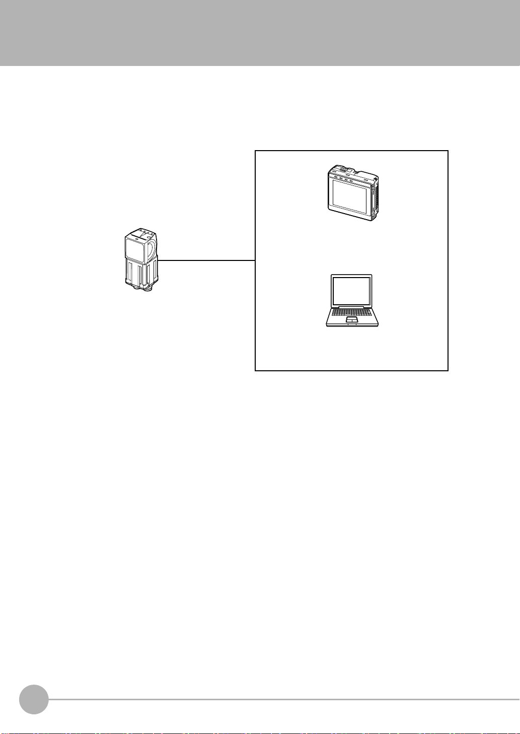
1-1 Fixed Mount 2D Code Reader FQ-CR2
The same functions as those that are provided
by the Touch Finder can be performed from a
computer. The PC Tool is available free of
charge.
Includes the camera, lighting, measurement
processor, and I/O functions.
After the Sensor has been set up, it can be
operated alone to perform measurements
without the Touch Finder or PC Tool.
PC Tool
Used to check images and set the judgement
parameters. It can also be used to save
measurement results and check status during
operation.
Fixed Mount 2D Code Reader
FQ-CR2
Touch Finder
Setup, Image Confirmation, and Logging Tools
The FQ-CR2 is a fixed mount 2D code reader that is easy t o us e and has advanced scanning features. Once
configured, they are used stand-alone for quality inspection of presence, position, and other product
characteristics. To set up or monitor the sensors, either the touch screen based console 'Touch Finder' or a 'PC
Tool' can be used.
12
Fixed Mount 2D Code Reader FQ-CR2
FQ-CR2 User’s Manual
Page 15

1-2 Measurement Process
Measurement
Logging
This section describes the basic flow of the measurement pr ocess.
Trigger input
Take image
Output
• The measurement is started by inputting a trigger signal from an external
device.
• Images are taken according to the trigger.
• The image is measured to see if it matches the configured settings.
• The overall judgement of all inspection items are output using OR logic.
• You can output detailed measurement results from the inspection items.
(An Ethernet connection is required.)
• Measurement data an d image data can be logged in memory in the Sensor or
in an SD card.
1
Introduction
FQ-CR2 User’s Manual
Measurement Process
13
Page 16
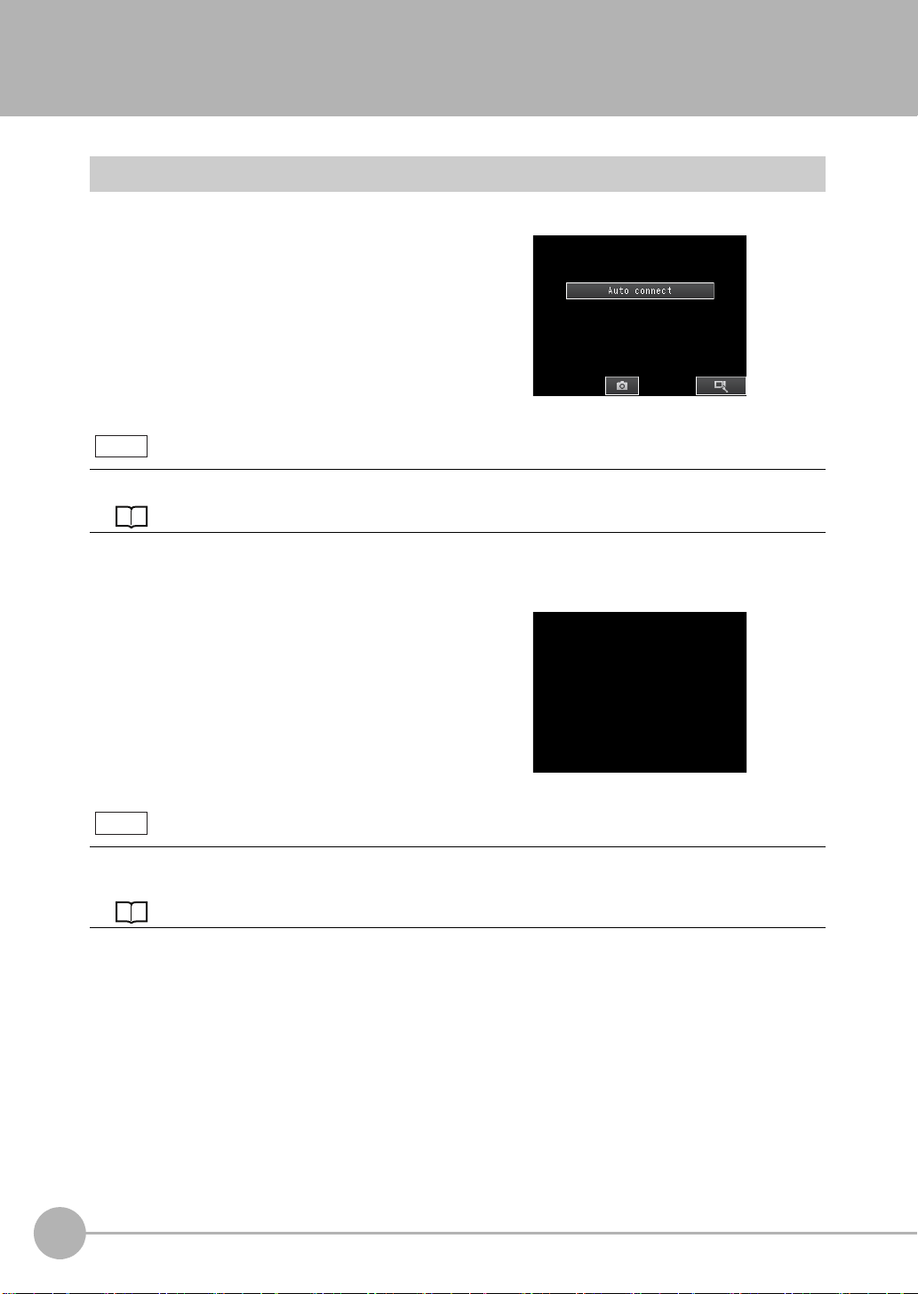
1-3 Startup Display and Display Elements
Startup Display
1 The Se nsor is automatically detected by the T ouch
Finder when power supply to the Se nsor and Tou ch
Finder is turned ON.
The Auto Connect Display will appear if the Sensor cannot be detected. Check that cables are connected correctly to the Sensor and Touch Finder, and then press
[Auto connect].
Note
If the Sensor is still not detected after pressing [Auto Connect], refer to the following information.
The Sensor cannot be detected: p. 156
2 When the Sensor is detected, the following display will appear.
Note
When the Touch Finder is started, IP addresses are automatically set for each Sensor.
To allocate specific IP addresses, set the IP address of each Sensor and the Touch Finder.
Setting Up Ethernet: p. 31
14
Startup Display and Display Elements
FQ-CR2 User’s Manual
Page 17

Display Elements
Tool Button: Used to call functions, such as saving data or select scenes.
Capture Button: Used to capture the current screen to the SD card.
This button menu is always displayed.
[Image]: Used to adjust the image.
[In/Out]: Used to set the I/O.
[Run]: Used to switch to Run Mode.
[Test]: Used to test and adjust the set measurements.
[Inspect]: Used to set the inspection items.
The setup flow is shown by these five tabs.
• If the [ ] Button appears, pressing it will display the
sub-menu or commands.
• Buttons will appear on the right according to the mode.
The menu changes according to the selected tab page.
The selected scene number is displayed.
The name of the Sensor being set up is displayed.
Only-image Button: Used to select either displaying the camera image and messages, or
only the camera image.
Display Button: Used to select the source of the image or to zoom the image.
The name of the mode or the
menu hierarchy is displayed.
p. 87
Display Functions: p. 72
This Sensor has a Setup Mode and a Run Mode.
Refer to the following information for menu items.
p. 158
Setup Mode
In Setup Mode, you can set the image conditions, judgement parameters, and I/O settings for the Sensor.
1
Introduction
Note
The Display Button can be used to switch between the following images.
• Live: The live image is displayed.
• Freeze: The image that was taken last is displayed.
• Log: An image saved in internal memory is displayed.
• File: An image saved on an SD card is displayed.
Run Mode
In Run Mode, measurements are performed, and measurement results are output.
p. 59
FQ-CR2 User’s Manual
Startup Display and Display Elements
15
Page 18
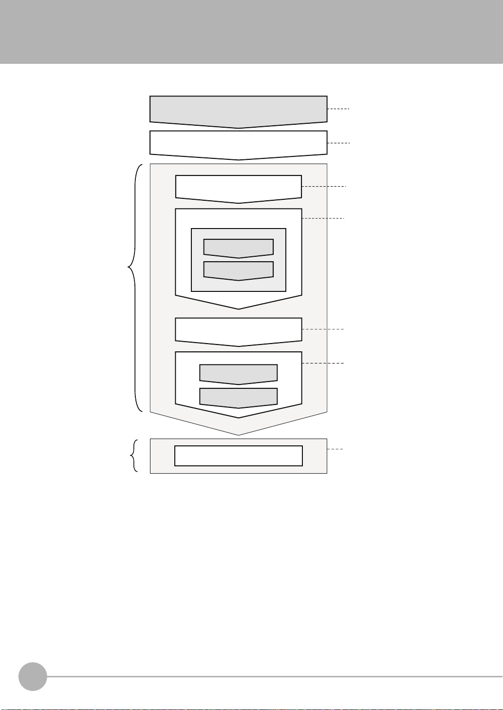
1-4 Basic Operational Flow
Operation
*2
Starting Operation (Run Mode)
Saving the Settings
Test Measurement and
Results Verification
Testing ([Test] Tab Page)
Output Settings
([In/Out] Tab Page)
Setup Evaluation
*1
Inspection Setup
([Inspect] Tab Page)
Teaching
Registering
Inspection Items
Image Setup
([Image] Tab Page)
Starting the Sensor
Connections and Wiring
Inspection
Section 2 Installation
and Connections
Section 1
1-3 Startup Display
and Display Elements
Section 3 Taking
Images
Section 4 Setting Up
Inspections
Section 8
Communications with
External Devices
Section 5 T esting and
Saving Settings
Section 6 Operation
The following flow shows the basic operation of FQ-CR2 Sensors.
*1: In Setup Mode, the Sensor can be set up and adjusted, but it does not output signals on the I/O lines.
*2: In Run Mode, the Sensor performs measurements and outputs signals on the I/O lines.
16
Basic Operational Flow
FQ-CR2 User’s Manual
Page 19

Installation and Connections
2-1 System Configuration . . . . . . . . . . . . . . . . . . . . . . . . . . . . . . . . . . . . . .18
2-2 Part Names and Functions . . . . . . . . . . . . . . . . . . . . . . . . . . . . . . . . . .19
2-3 Installation . . . . . . . . . . . . . . . . . . . . . . . . . . . . . . . . . . . . . . . . . . . . . . . 21
2-4 Wiring . . . . . . . . . . . . . . . . . . . . . . . . . . . . . . . . . . . . . . . . . . . . . . . . . . .26
2-5 Setting Up Ethernet . . . . . . . . . . . . . . . . . . . . . . . . . . . . . . . . . . . . . . . .31
2
Installation and Connections
Page 20
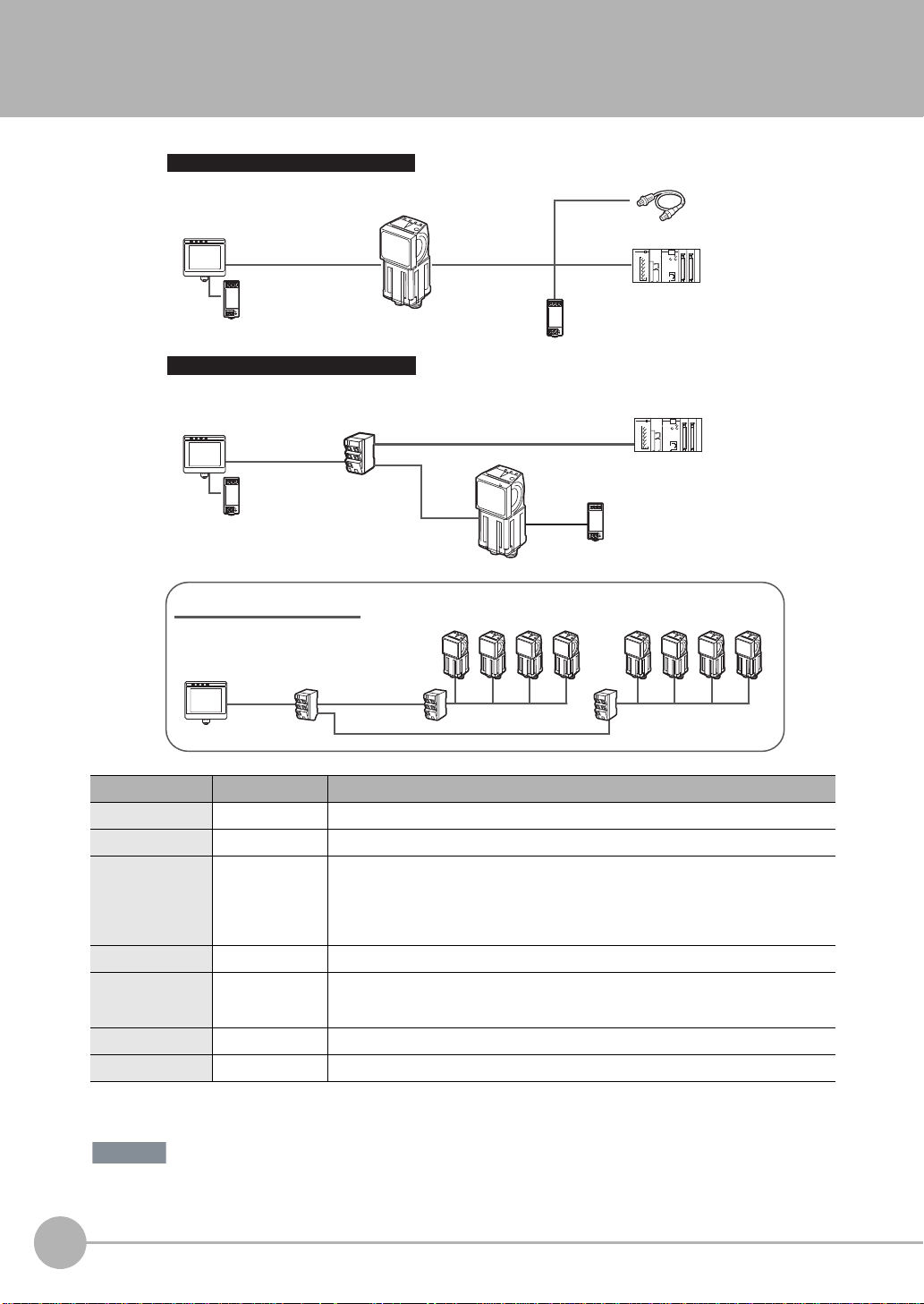
2-1 System Configuration
Multiple Connection Sensors
Connecting to Ethernet
PLC
24-VDC power supply
24-VDC power
supply
FQ Ethernet Cable I/O Cable
Touch Finder or PC Tool
Setup Tool
FQ Sensor
Parallel Interface Connection
Trigger Sensor
Touch Finder or PC Tool
Setup Tool
Switching Hub
Switching HubSwitching Hub
Switching Hub
Touch Finder or PC Tool
Setup Tool
Standard RJ45 Ethernet Cable
Standard RJ45
Ethernet Cable
Standard RJ45
Ethernet Cable
Standard RJ45 Ethernet Cable
FQ Sensors (8 max.)
FQ Ethernet Cable FQ Ethernet Cable
Standard RJ45
Ethernet Cable
FQ
Sensor
24-VDC power
supply
Standard RJ45
Ethernet Cable
I/O Cable
PLC to control Sensor
24-VDC power
supply
Important
Product Model number Remarks
FQ Sensor
Touch Finder FQ-D@@ This is a setup console (Software Version 1.3 or higher).
PC Tool --- The PC Tool can be used instead of the Touch Finder (Software Version 1.3 or higher). If
FQ Ethernet Cable FQ-WN0@@ Connects the Sensors to external devices such as t he Touch Finder, computers, and PLCs.
Standard RJ45
Ethernet Cable
I/O Cable FQ-WD0@@ Connects the Sensor to the power supply and external devices.
Switching Hub W4S1-0@@ Used to connect multiple Sensors to one Touch Finder or PC Tool.
*1: The shape and dimensions of the Ethernet connector plug and jack are specified in ISO/IEC8877:1992 (JIS X 5110:1996) and RJ-45 of the
FCC regulations. T o pre v ent connector connection failures , the structure of the jack of this product does not allow insertion of plugs that do not
comply with the standard. If a commercially available plug cannot be inserted, it is likely that the plug is non-compliant.
Do not connect network devices other than PLCs on the same network as the Touch Finder or computer. If
another device is connected, the responsiveness of displays and settings of the Touch Finder or computer may
become slow.
18
System Configuration
FQ-CR2
@@@@@
-M
This is the Sensor.
you register as a member, you can download the free PC Tool as a special service to
purchasers.
Refer to the Member Registration Sheet that is enclosed with the Sensor for the member
registration procedure and the download procedure for special member software.
--- Connects the Switching Hub to the Touch Finder, computers, and PLCs. Use a connector
*1
that complies with the FCC RJ45 standard. (STP (shielded twisted-pair) cable, category 5e
or 6, impedance: 100 Ω)
FQ-CR2 User’s Manual
Page 21
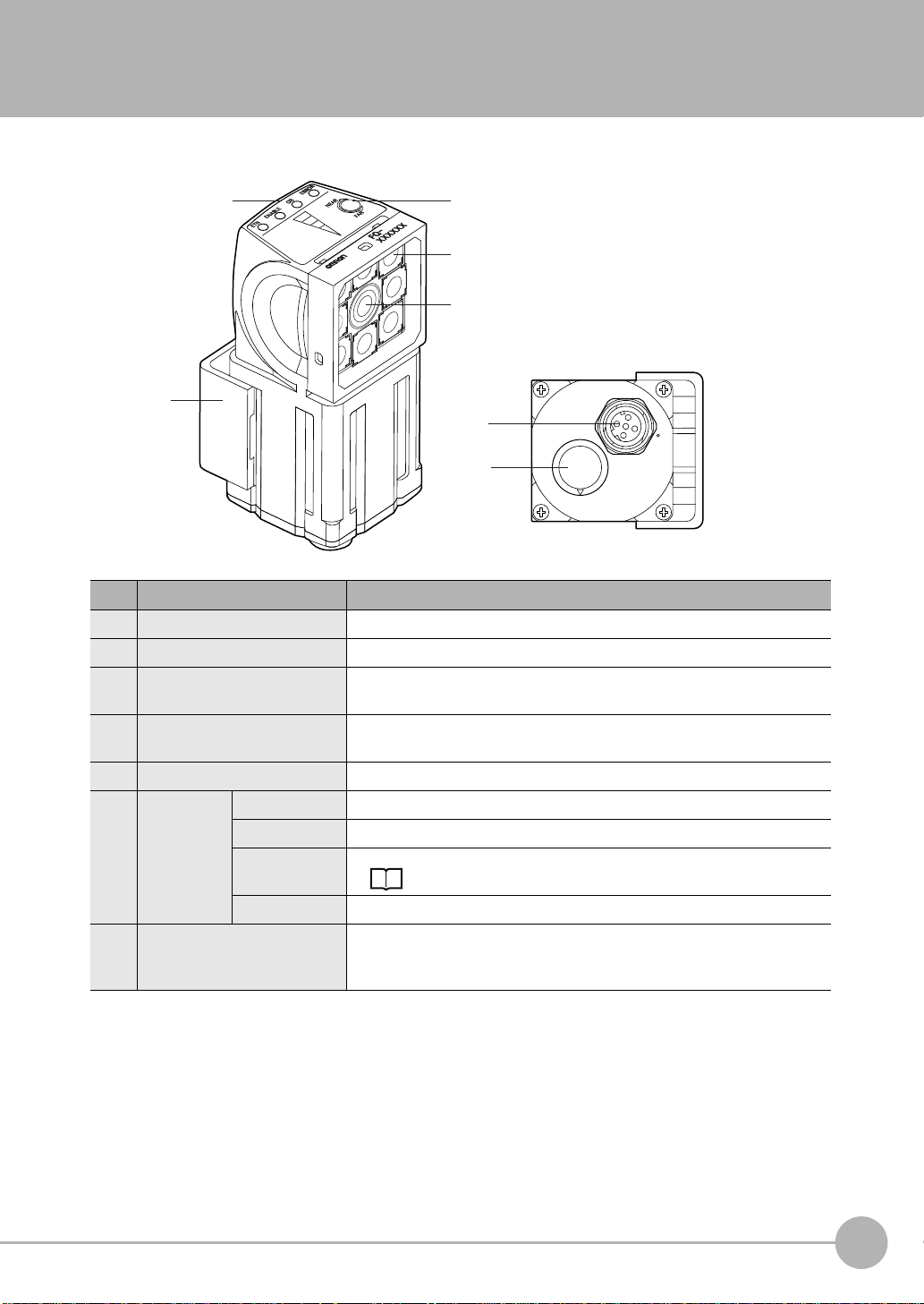
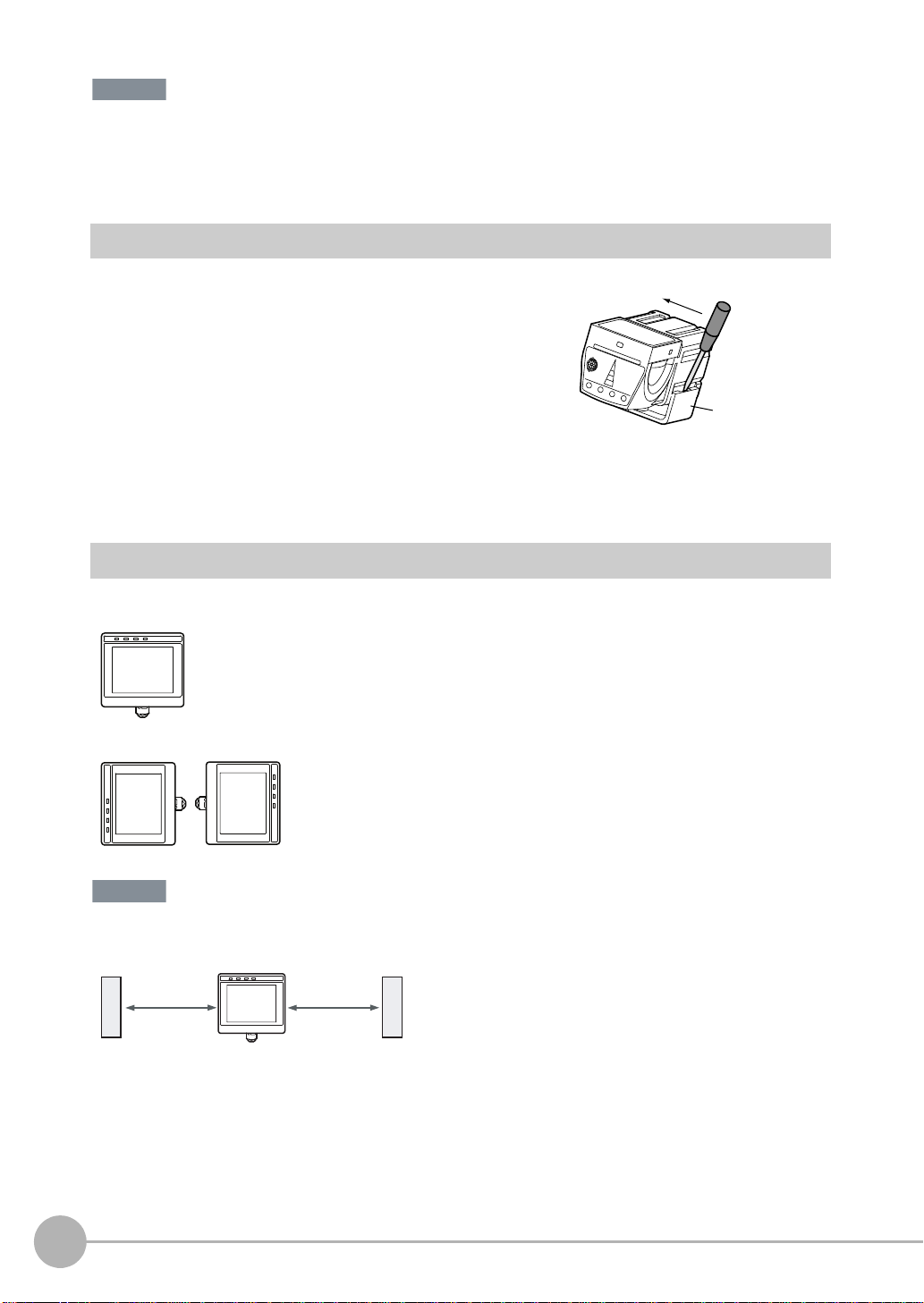
2-2 Part Names and Functions
(2)
(3)
(5)
(1)
(6)
(7)
(4)
FQ Sensor
No. Name Description
(1) Lighting LEDs for illumination
(2) Camera lens This lens can be focused.
(3) I/O Cable connector An I/O Cable is used to connect the Sensor to the power supply and exter-
nal I/O.
(4) Ethernet cable connector An Ethernet cable is used to connect the Sensor to external devices such as
PLCs, the Touch Finder, or computers.
(5) Focus adjustment screw Used to adjust the focus of the image.
(6) Operation
indicators
(7) Mounting Bracket Used to mount the Sensor.
OR Lights orange when the OR output signal turns ON.
ETN Lights orange during Ethernet communications.
ERROR Lights red when an error occurs.
9-1 Error Table p. 154.
BUSY Lights green when the Sensor is executing a process.
The Mounting Bracket can be attached to the front, left side, right side, or
back of the Sensor.
2
Installation and Connections
FQ-CR2 User’s Manual
Part Names and Functions
19
Page 22
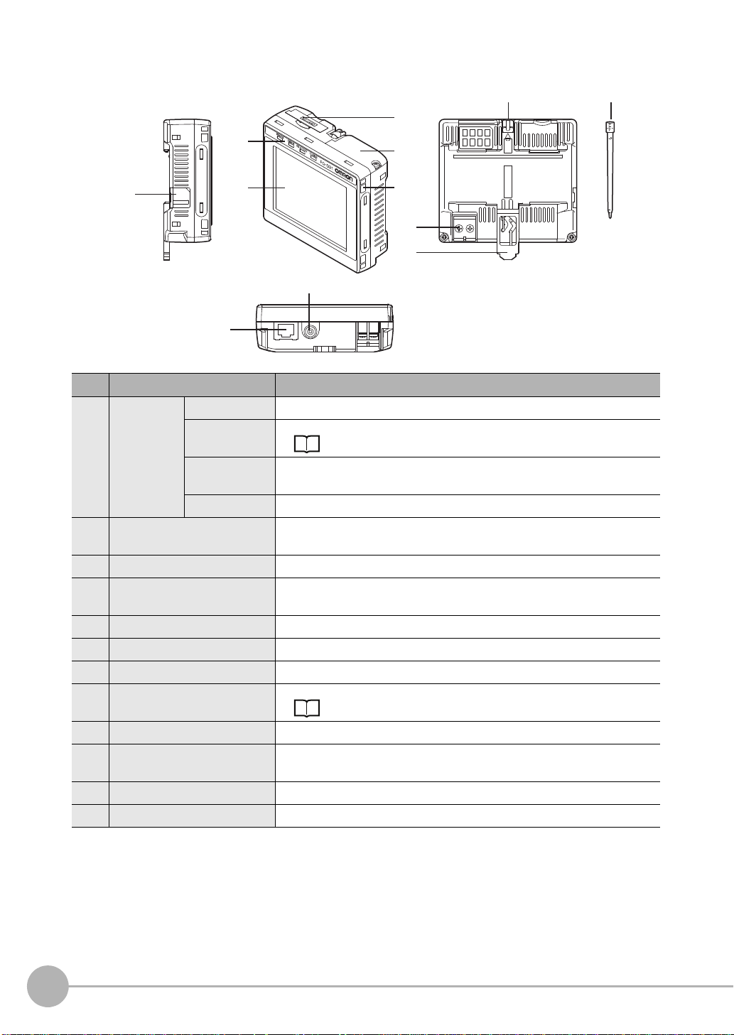
Touch Finder
(1)
(6) (7)
(3)
(4)
(5)
(2)
(12)
(10)
(11)
(8)
(9)
No. Name Description
(1) Operation
indicators
(2) LCD/touch panel Displays the setting menu, measurement results, and images input by the
(3) SD card slot An SD card can be inserted.
(4) Battery cover
(5) Power supply switch Used to turn the Touch Finder ON and OFF.
(6) Touch pen holder The touch pen can be stored here when it is not being used.
(7) Touch pen Used to operate the touch panel.
(8) DC power supply connector Used to connect a DC power supply.
(9) Slider Used to mount the Touch Finder to a DIN Track.
(10) Ethernet port Used when connecting the Touch Finder to the Sensor with an Ethernet
(11) Strap holder This is a holder for attaching the strap.
(12) AC power supply connector*1Used to connect the AC adapter.
*1: Applicable to the FQ-D31 only .
POWER Lights green when the Touch Finder is turned ON.
ERROR Lights red when an error occurs.
9-1 Error Table p. 154.
SD ACCESS Lights yellow when an SD card is inserted.
Flashes yellow when the SD card is being accessed.
CHARGE
*1
*1
Lights orange when the Battery is charging.
camera.
The Battery is inserted behind this cover.
Remove the cover when mounting or removing the Battery.
p. 28
cable. Insert the connector until it locks in place.
20
Part Names and Functions
FQ-CR2 User’s Manual
Page 23
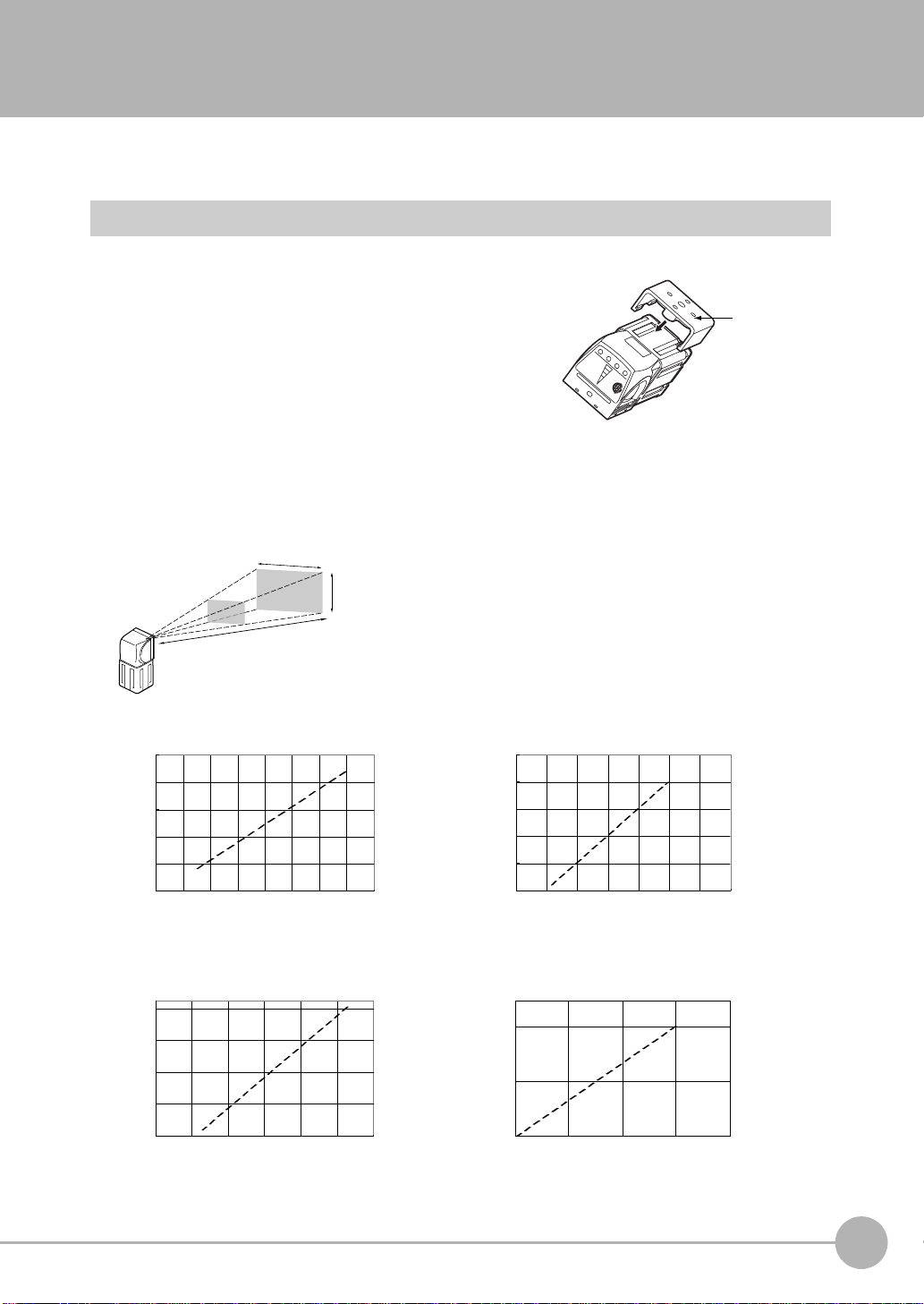
2-3 Installation
Mounting
Bracket
6
8 10 12 14
0 20 40 60
50
130
210
0 100 200 300
35
45
55
200
600
1,000
200 400
0
0
400
Horizontal field of view (mm)
Horizontal field of view (mm)
Installation distance (L) (mm)
Installation distance (L) (mm)
FQ-CR20050F-M, FQ-CR25050F-M
FQ-CR20100N-M, FQ-CR25100N-M
Horizontal field of view (mm)
Horizontal field of view (mm)
Installation distance (L) (mm)
Installation distance (L) (mm)
FQ-CR20010F-M, FQ-CR25010F-M
FQ-CR20100F-M, FQ-CR25100F-M
Installation distance (L)
Vertical field
of view
The optical chart indicates the horizontal
field of view. The vertical field of view will
be approximately 60% of the horizontal
field of view.
Horizontal field of view
Note: The tolerance is ±10%.
Installing the Sensor
Installation Procedure
1 Align the tabs on one side of the Moun ting Bracket with
the slot on the Sensor.
The FQ-XL Mounting Bracket can be attached to the back,
side, or front of the Sensor.
2 Press the Mounting Bracket onto the Sensor until the oth-
er tabs click into place.
3 Use the following optical charts to check the field of view
and installation distance of the Sensor so that it is mou nted at the correct position.
Tightening torque (M4): 1.2 N·m
2
Installation and Connections
FQ-CR2 User’s Manual
Installation
21
Page 24
• There is a certain amount of deviation among Sensors in the center of the optical axis. For this reason, when install-
Important
Important
15 mm min.
15 mm min.
ing the Sensor, check the center of the image and the field of view on the LCD monitor of the Touch Finder and in
the PC Tool.
Removal Procedure
1 Insert a flat-blade screwdriver between the Mounting Brack-
et and the Sensor case on either side and remove the
Mounting Bracket.
Mounting
Bracket
Installing the Touch Finder
Installation Precautions
Install the Touch Finder in the following orientation to allow sufficient heat dissipation.
22
Do not mount it in the following orientations.
• To improve ventilation, leave space on both sides of the Touch Finder. The distance between the Touch Finder and
other devices should be at least that shown in the following diagram.
• Make sure that the ambient temperature is 50°C or lower. If it exceeds 50°C, install an cooling fan or an air conditioner and maintain the temperature at 50°C or lower.
• To prevent interference by noise, do not mount the Sensor on panels which contain high-voltage devices.
• To keep the level of noise from the surrounding environment to a minimum, install the Sensor and Touch Finder at
least 10 m away from power lines.
Installation
FQ-CR2 User’s Manual
Page 25
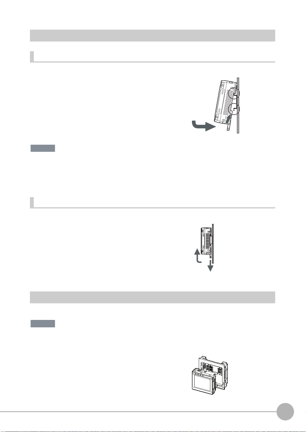
Mounting to DIN Track
Important
Important
Installation Procedure
1 Press the slider on the Touch Finder to the top.
2 Hook the clip at the top of the Touch Finder on to the DIN
Track.
3 Press the Touch Finder onto the DIN Track until the bottom
clip clicks into place.
3
• Attach End Plates (sold separately) on the sides of the Touch Finder on the DIN Track.
• If other devices will be installed next to the Touch Finder on the same DIN Track, make sure that sufficient space is
kept between the devices as indicated on previous page.
•Always hook the clip at the top of the Touch Finder on the DIN Track first. If the lower clip is hooked on first, the
Touch Finder will not be mounted very securely.
Removal Procedure
2
3
1
1 Pull down on the slider on the Touch Finder.
2 Lift the Touch Finder at the bottom and remove it from the
DIN Track.
2
1
2
Installation and Connections
Mounting to a Control Panel
The Touch Finder can be mounted on a panel using the FQ-XPM Panel Mounting Adapter.
•Always turn OFF the Touch Finder power before attaching or detaching the Panel Mount Adapter. Attaching or
detaching with the power turned ON may cause a failure.
1 Set the To uc h Finde r in the Pa ne l Mou nt Ada pter.
FQ-CR2 User’s Manual
Installation
23
Page 26
2 Press the slider up on the Touch Finder.
3 Create holes in the panel for mounting.
Refer to the following page for hole dimensions.
p. 176
4 Connect the cable to the Touch Finder.
5 Mount the Touch Finder with the Panel Mount Adapter from
the front of the panel.
6 Hook the hooks on the Mounting Bracket in the four holes
of the Panel Mount Adapter and secure them with screws.
(Tightening torque: 1.2 N·m)
7 Check that the Touch Finder is attached properly to the
Panel.
Mounting
Bracket
Using the Touch Finder as a Portable Device (with Battery)
The Touch Finder with a Battery can be used as a portable device. Use the strap when carrying it to prevent
dropping it.
There are two types of straps (FQ-XH, sold separately), a Neck Strap and a Hand Strap.
Neck Strap
Hand Strap
1 Attach the Mini-strap to the Touch Finder.
There are a total of four holes for at taching the Mini-strap on the left and o n the right of the Touch Finder.
24
Installation
FQ-CR2 User’s Manual
Page 27

2 Connect the Neck Strap or Hand Strap to the Mini-strap.
Mini-strap
Neck Strap or Hand
Strap
2
Installation and Connections
FQ-CR2 User’s Manual
Installation
25
Page 28
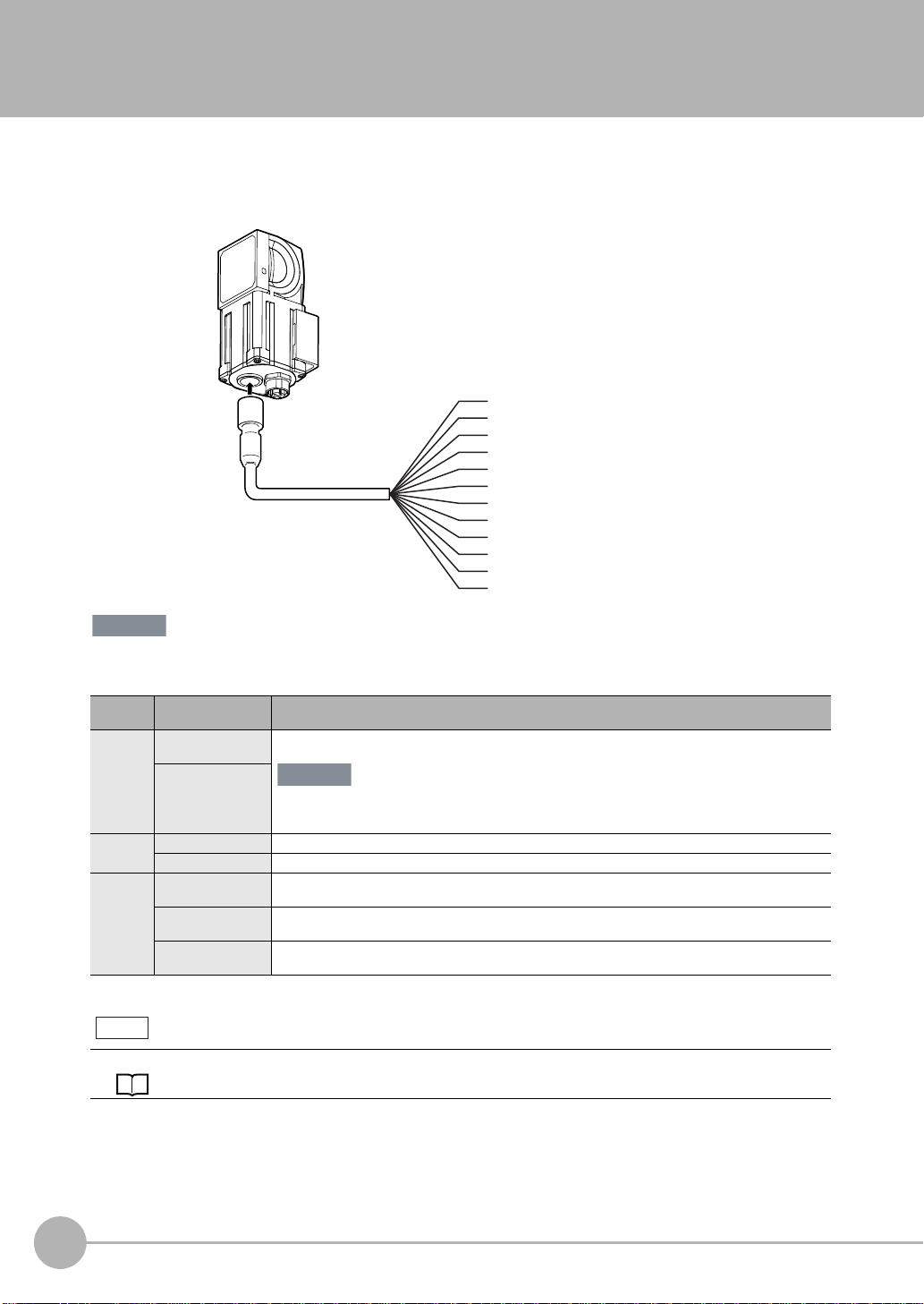
2-4 Wiring
GND
OUT0 (OR)
OUT1 (BUSY)
OUT2 (ERROR)
IN0
TRIG
IN1
IN2
IN3
IN4
IN5
Yellow
Purple
White
Red
Green
FQ-WD0@@
I/O Cable
Gray
Pink
Light blue
Orange
Black
Blue
Power supply
Brown
Important
Important
Wiring the Sensor
Connect the I/O Cable to the I/O Cab le connector located at the bottom of the Sensor.
26
Cut off lines that are not required so that they do not come into contact the other signal lines.
Classification
Power
supply
Inputs TRIG This terminal is the trigger signal input.
Outputs OUT0 (OR) By default, this is the OR output signal (overall judgement).
The assignments of I/O signals can be changed.
Wiring
Signal Application
Power supply
(24 V)
GND
IN0 to IN5 These are the command input terminals.
OUT1 (BUSY) By default, this is the BUSY output signal.
OUT2 (ERROR) By default, this is the ERROR output signal.
Note
Section 8 Communications with External Devices: p. 95
These terminals are for the external power supply (24 V).
Wire the power supply separately from other devices. If the wiring for other de vices is placed
together or in the same duct as the wiring fo r the Sensor, the influences of electromagnetic induction
may cause the Sensor to malfunction or may damag e it.
The assignment can be changed to an individual judgement signal from OR0 to OR31.
The assignment can be changed to an individual judgement signal from OR0 to OR31.
The assignment can be changed to an individual judgement signal from OR0 to OR31.
FQ-CR2 User’s Manual
Page 29
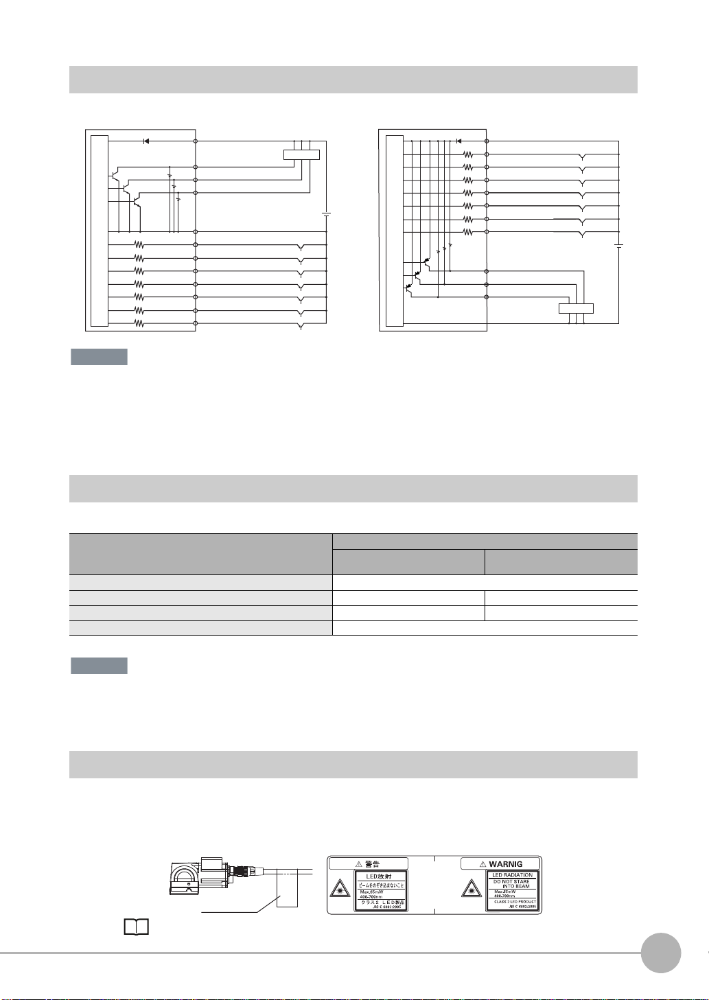
I/O Signal Circuit Diagrams
GND (0V)
OUT0 (OR)
OUT1 (BUSY)
OUT2 (ERROR)
TRIG
IN0
IN1
IN2
IN3
IN4
IN5
PNPNPN
IN0
IN1
IN2
IN3
IN4
IN5
TRIG
GND (0V)
OUT0 (OR)
OUT1 (BUSY)
OUT2 (ERROR)
Brown
Power supply (24 VDC)
24 VDC
Yellow
Blue
Load
Purple
White
Black
Red
Orange
Light blue
Green
Gray
24 VDC
Pink
Blue Yellow
Internal circuits
Internal circuits
Purple
White
Light blue
Red
GreenOrange
Black
Gray
Load
Pink
Brown
Power supply (24 VDC)
Important
Important
Attachment Example
Warning Label
Warning Label
Preventing Chattering
• The Sensor is equippe d with an an ti-chatter ing function, but if the chattering is 100 μs or longer, a faulty input may
occur. (Input signals of 99 μs or shorter are ignored. Signals of 100 μs or longer are treated as input signals.)
• Use no-contact output devices (e.g., SSR or PLC transistor output) for the input signals. If contacts (e.g., relay) are
used, chattering may cause the trigger to be input again during execution of a measurement.
2
Installation and Connections
Po wer Supply Specifications When a Switching Regulator Is Connected
Use a power supply that meets the following specifications. (The power supply is sold separately.)
Item Model
Power supply voltage 24 VDC (21.6 to 26.4 V)
Output current 1.25 A max. 2.5 A max.
Recommended Power Supply S8VS-030024@ (24 VDC, 1.25 A) S8VS-060024@ (24 VDC, 2.5 A)
External power supply terminal screws M4 (Tightenin g to r q ue : 1.2 N·m)
Supply power from a DC power supply for which measures have been applied to prevent high voltages (e.g., a safety
extra low voltage circuit).
If UL certification is required for the overall system, use a UL Class II DC power supply.
Attaching the LED Warning Label
Attach the enclosed LED warning label to the cable or other location. The LED warning label must be attached
to a location that is readily visible from the Sensor.
FQ-CR2 User’s Manual
FQ-CR2@010F-M/
FQ-CR2
@
050F-M
10-5 LED Safety p. 181
FQ-CR2@100F-M/
FQ-CR2
@
100N-M
Wiring
27
Page 30
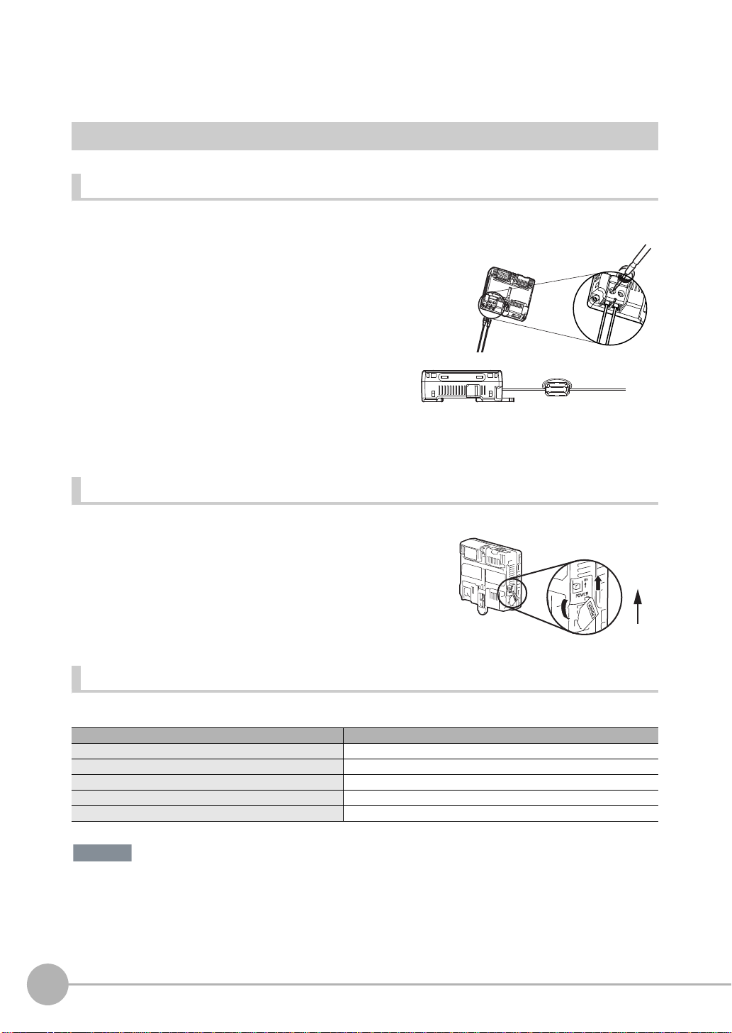
Wiring the Touch Finder
1
2
ON
OFF
Important
Power Supply Wiring
Connecting the Power Supply
1 Loosen the two terminal screws using a Phillips
screwdriver.
2 Attach crimp terminals to the power lines.
Secure the positive and negative lines as indicated
using M3 screws.
Power supply tightening torque: 0.54 N⋅m
3 In environments where there is excessive noise, at-
tach a ferrite core (ZCAT1730-0730 from TDK or the
equivalent) to the power supply cable.
Turning ON the Touch Finder
24 VDC
When you attach the ferrite core to
the power supply cable, wrap the
cable only one time.
+
−
28
1 Remove the cover from the power switch on the left side of
the Touch Finder.
2 Press the switch toward ON.
Power Supply Specifications
Use a power supply that meets the following specifications. (The power supply is sold separately.)
Item Description
Power supply voltage 24 VDC (21.6 to 26.4 V)
Output current 0.65 A min.
Recommended Power Supply S8VS-01524@ (24 VDC, 0.65 A)
External power supply terminal screws M4 (tightening torque: 1.2 N⋅m)
Recommended power line wire size AWG16 to AWG22 (length of 5 m max.)
• Supply power from a DC power supply for which measures have been applied to prevent high voltages (e.g., a
safety extra low voltage circuit).
If UL certification is required for the overall system, use a UL Class II DC power supply.
• When using the FQ-D31, do not connect a switching regulator and AC Adapter (FQ-AC@) at the same time.
Wiring
FQ-CR2 User’s Manual
Page 31

Charging the Battery
Important
CHARGE indicator
This section describes how to charge and install the FQ-D31 Battery and provides applicable precautions.
Charge the Battery while it is attached to the Touch Finder.
Use the AC adapter to charge the battery.
Mounting the Battery in the Touch Finder
1 Remove the screw from the battery cover on the top of the
Touch Finder, slide the cover in the direction of the arrow,
and open the battery cover.
2 Face the rounded side of the battery toward the back of the
Touch Finder and insert the battery.
Do not insert the battery in the wrong orientation.
3 Close the battery cover, slide the battery cover in the direc-
tion of the arrow, and tighten the screw on the battery cover.
2
Installation and Connections
4 Attach the AC adapter to the Touch Finder to start changing
the battery.
The CHARGE indicator will be lit while the battery is being
charged. It will go out when charging the batt ery ha s been co mpleted.
Note
The Touch Finder will operate even if the AC adapter is connected when no battery is mounted in the Touch Finder.
FQ-CR2 User’s Manual
Wiring
29
Page 32

• If the Touch Finder (FQ-D31) will be installed permanently or semi-permanently, remove the Battery (FQ-BAT1). If
Important
EU
Li-ion00
Japan Taiwan
the rated temperature is exceeded with the Battery inserted, the protective circuit may activate and stop the Touch
Finder.
• The battery complies with the following recycling regulation.
• California regulations concerning perchlorate:
This product is a lithium battery that contains perchlorate, which is regulated by the State of California. Please comply with these regulations. For details see the following URL:
www.dtsc.ca.gov/hazardouswaste/perchlorate/
30
Wiring
FQ-CR2 User’s Manual
Page 33

2-5 Setting Up Ethernet
Connecting to Sensors from the Touch Finder
When the Sensor is used with a Touch Finder, IP addresses are automatically assigned. No settings are
required to use Ethernet.
However, if a Sensor or Touch Finder is connected to a network where a PLC or computer is already
connected, the Ethernet must be set to be compatible with the existing network.
• Sensor
(Setup Mode) − [Sensor settings] − [Network] − [Ethernet]
1 Set [Auto conn ection] to [OFF].
2 Set the IP address and subnet mask according to the network settings.
• Touch Finder
(Setup Mode) − [TF settings] − [Ethernet]
1 Set the IP address and subnet mask according to the network settings.
Connecting to Sensors from External Devices Such as PLCs
2
Installation and Connections
Set the IP address of the Sensor according to the network where the external devices, such as PLCs, are
connected.
(Setup Mode) − [Sensor settings] − [Network] − [Ethernet]
1 Set [Auto] to [OFF].
2 Set the IP address and subnet mask according to the network where the external devices, such
as PLCs, are connected.
Note
If you connect OMRON CS/CJ-series PLCs to the Ethernet, the following default IP addresses are assigned to the
PLCs.
• IP address: 192.168.250.node_address
Connecting to Sensors from a Computer Using the PC Tool
When connecting the Sensor directly to a computer using an Ether net Cable, set the network settings on the
computer as given belo w. Setting a fixed IP address is not required if there is a hub between the computer and
Sensor and a DHCP server is used.
The following procedure is for Windows XP.
1 Select [Control Panel] from the Windows Start Menu.
2 Click [Network and Internet Connections] in the control
panel and then double-click [Network Connections].
FQ-CR2 User’s Manual
Setting Up Ethernet
31
Page 34

3 Right-click the [Local Area Connection] Icon and select
[Properties].
4 On the [General] Tab Page, double-click Internet Proto-
col (TCP/IC).
5 Select the Use the following IP address Option and en-
ter the following IP address and subnet mask.
• IP address: 10.5.5.101
• Subnet mask: 255.255.255.0
6 Click the [OK] Butto n. This compl e tes the setting s.
32
Setting Up Ethernet
FQ-CR2 User’s Manual
Page 35

Taking Images
3-1 Selecting a Sensor for Configuration. . . . . . . . . . . . . . . . . . . . . . . . . . 34
3-2 Adjusting Image Quality . . . . . . . . . . . . . . . . . . . . . . . . . . . . . . . . . . . . 35
3-3 Adjusting the Object Position . . . . . . . . . . . . . . . . . . . . . . . . . . . . . . . . 41
3-4 Preventing Mutual Interference of Multiple Sensors . . . . . . . . . . . . . 43
3-5 Setting How the Image is Processed After Scanning . . . . . . . . . . . . . 44
3
Taking Images
Page 36

3-1 Selecting a Sensor for Configuration
Note
If multiple Sensors are connected to a single Touch Finder or computer, you can select the Sensor that you
want to set up.
1 Press [Run].
This will enable setting the current Sensor into RUN
Mode before selecting another Sensor.
2 Then press [Switch to Run mode].
3 Press [Yes].
4 Press − [Switch Sensor].
5 Press the image of the Sensor to be set up.
will be displayed for Sensors that are not yet set.
Once the Touch Finder detects and records a Sensor, the display order for showing more than one Sensor is fixed. Even if the system
configuration is changed to reduce the number of Sensors, the previous display location will remain for Sensors that were removed.
To update displays of multiple Sensors to the current connection sta-
tus, press [ ] - [Auto connect] on the right of the display in step 5,
above, to automatically reconnect.
6 Press − [Sensor settings] to return to Setup
Mode.
7 Press [Yes].
34
Selecting a Sensor for Configuration
FQ-CR2 User’s Manual
Page 37

3-2 Adjusting Image Quality
Focus Level
(The field of view will widen.)
Turn the screw counterclockwise
to focus on objects at a distance.
(The field of view will
narrow.)
Turn clockwise to focus on closer objects.
Focus adjustment screw
Important
Adjusting the Focus
[Image] − [Camera setup]
1 Display the Camera Setup Display.
The focus can be seen as a numerical value. The higher
the value, the better the focus.
2 Manually adjust the focus using the focus adjust-
ment screw on the Sensor while checking the image
and focus value on the Touch Finder.
In the default settings, the field of view is set to the narrowest setting.
3 Press [Back].
3
Taking Images
• Turn the focus adjustment screw clockwise or counterclockwise a little bit to make sure that it has not already
reached the dead stop. Do not force the screw if it does not rotate anymore. This will damage the Sensor.
• Do not turn the focus adjustment knob with a force that is greater than 0.1 N·m. This may damage it.
FQ-CR2 User’s Manual
Adjusting Image Quality
35
Page 38

Increasing the Brightness of the Image
Important
The brightness of the display can be adjusted by adjusting the shutter speed and gain. To automatically adjust
the shutter time and gain, press the [AUTO] button in the display. To set the shutter speed and gain individually,
follow the steps below.
The image can be made brighter by increasing the shutter speed.
1 Press [Shutter speed] on the right side of the display.
2 Move the ad justment bar left or right to adjust the
brightness of the display.
3 Press [OK].
The exposure time is longer when a larger value is set. This may cause the image to blur if the object is mo vin g
fast. When using the reader on a high-speed line, verify that the image is not blurred under actual operating
conditions.
If sufficient brightness cannot be obtained by adj usting the shutter speed, increase the gain.
1 Press [Gain] on the right side of the display.
2 Move the ad justment bar left or right to adjust the
brightness of the display.
3 Press [OK].
36
Adjusting Image Quality
FQ-CR2 User’s Manual
Page 39

If the image brightness fluctuates and is not stable each time an image is captured, turn on brightness
Important
Important
correction.
[Brightness] - [] - [Brightness correction].
[Shutter speed] - [] - [Brightness correction].
[Gain] -
[] - [Brightness correction].
When brightness correction is turned on, the brightness stabilizes but the image timing is delayed by 25 ms.
Make sure that suitable images of the measured objects are captured when brightness correction is on.
Timing chart when brightness correction is ON
Timing Chart When the Brightness Correction Mode Is ON
Image capture starts 25 ms
after TRIG signal input.
TRIG signal
(Brightness
correction ON)
BUSY signal
ON
OFF
ON
OFF
ON for 1 ms or longer
ON while measurement
processing is executed
Timing chart when brightness correction is off: p.97
Capturing Moving Objects Without Blur
For fast moving objects, blurring can be reduced by decreasing the shutter speed.
1 Press [Shutter speed] on the right side of the display.
2 Move the adjustment bar left or right to adjust the gain.
3 Press [OK].
If sufficient brightness cannot be obtained by adj usting the shutter speed, increase the gain.
3
Taking Images
When the shutter speed is decreased, the image becomes darker. Increasing the gain can improve the
brightness, but the image will become grainier. Make sure that measurement stability is not affected under
actual operating conditions.
Improving the Image Quality of Objects with Shiny or Metallic Surfaces
When measuring objects with shiny or metallic surfaces, light may reflect off the surface and affect the image.
Two functions are available to remove reflected light from the image.
Function Description
HDR
(High Dynamic Range)
Polarizing filter A polarizing filter can be attached to the sensor to remove specular reflection.
Hints
• The object being inspected can be stopped Use the HDR function
• The object being inspected cannot be stopped Use the polarizing filter
FQ-CR2 User’s Manual
Widens the dynamic range to improve the image quality of objects with contrasting light and dark areas.
Adjusting Image Quality
37
Page 40

HDR Function
Inputting Images with a Limit Range of Brightness
Combining Images to Create an Image
with a Wide Dynamic Range
Dark
Bright
This function widens the dynamic range to improve the image quality of objects with contrasting light and dark
areas. This function is particularly effective for objects with highly contrasting light and dark areas, and when
bright objects are mixed together with dark objects.
Note the following points:
• Only use the HDR function when the inspected object is stopped.
Images are captured using different shutter speeds and combined. If the object moves, a blurred image will
result.
• Because images of differing brigh tness are combined, the resulting combined image will have slightly less
contrast.
[Image] - [Camera setup]
1 Press [ ] - [HDR] on the right side of the display.
Select the HDR level.
2 Press [ ] - [Brightness] on the right side of the dis-
play.
3 Move the ad justment bar left or right to adjust the
brightness.
A larger "Brightness" value makes the image brighter.
A smaller "Brightness" value makes the image darker.
38
Adjusting Image Quality
FQ-CR2 User’s Manual
Page 41

• Relation between brightness parameter and image brightness
100
0
Brightness of image
Bright
Dark
1000
1/30,000 1/250
Moving speed
Slow
Fast
Exposure time
Level 1
Level 2
Level 3
Level 4
Dark
Bright
• Relation between brightness parameter and shutter time
4 To automatically adjust HDR, press the [AUTO] but-
ton.
Note
• If the object is changed after the HDR function is set, press the
[AUTO] button to repeat auto adjustment.
• If auto adjustment does not achieve the desired result, press
- [HDR] on the right side of the display and manually select the
optimum HDR mode.
•As shown below, a higher level gives a wider combined dynamic
range.
[]
3
Taking Images
• If reflected light cannot be sufficiently removed using the HDR
function, use the polarizing filter in combination with the HDR
function.
FQ-CR2 User’s Manual
Adjusting Image Quality
39
Page 42

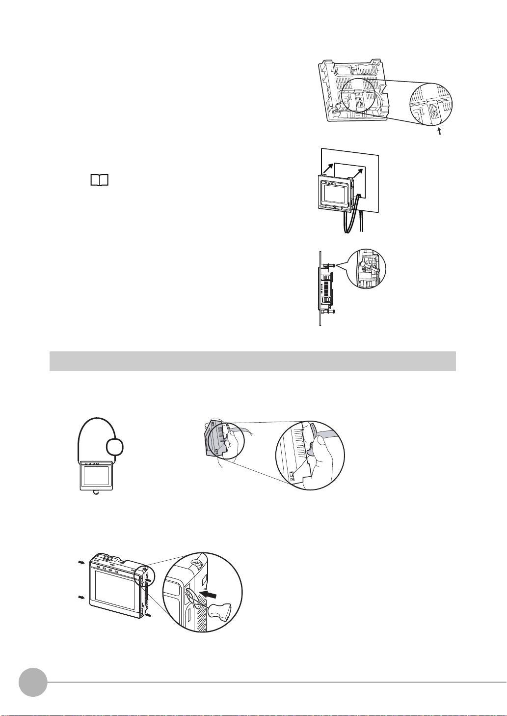
Using a Polarizing Filter
Specular reflections can be eliminated from an image b y attaching a FQ-XF1 Polarizing Filter to the Sensor.
Observe the following precautions .
• The image will be darker compared to when no filter is used.
• If the image becomes too dark, adjust the brightness.
p. 39
• Mounting the Filter
1 Hook the filter in the hole at the top of the Sensor.
2 Using the top section as a pivot point, pull down the
filter so that it attaches to the Sensor.
40
Adjusting Image Quality
FQ-CR2 User’s Manual
Page 43

3-3 Adjusting the Object Position
Trigger input Sensor
Delay from when the trigger is input until
when Sensor input is started.
Delay time
If objects are moving, the position in the image of the characteristic that is to be measured will vary according
to the timing of the trigger signal. The FQ Sensor offers two different ways to adjust this positi on variation.
Function Description Reference
Trigger delay A delay can be applied from when the trigger (the TRIG signal) is input until when the
image is input, to synchronize the timing of image input with the speed of the moving
objects.
Adjusting the Image Timing
The internal timing for taking an image can be set to be delayed in relation to the external trigger signal. This
can be used to adjust the object position in the image, e.g., if an exter nal trigger sensor is used. If the object
position still varies in the image the Position Compensation function must also be used.
p. 41
3
Taking Images
[Image] − [Trigger setup] − [Trigger delay]
1 A TRIG signal is input.
Images are input continuously.
2 Select the image with the measurement object in the
center using [ ] and [ ].
3 Press the image.
4 Press [OK].
FQ-CR2 User’s Manual
Adjusting the Object Position
41
Page 44

The delay time can be set using the adjustment bar or by directly entering a value.
Note
Directly input the delay time.
Or
Move the bar to the left or right.
42
Adjusting the Object Position
FQ-CR2 User’s Manual
Page 45

3-4 Pre venting Mutual Interference of Multiple Sensor s
Sensor 0
Sensor 1
Trigger Sensor
Important
When the same trigger signal is input to multiple Sensors, the lighting from one Sensor may affect the
measurements of the other Sensors. This is called mutual interference. This kind of interference can be
prevented offsetting the image input timing of each Sensor from when the trigger signal is received.
Example:
A trigger (i.e., the TRIG signal) is input to Sensor 0 and Sensor 1 at the same time.
TRIG signal
Timing of taking the image
Sensor 0
Sensor 1
Sensor 0 immediately begins image input when th e trigger is input.
Sensor 1 begins image input after the specified time has passed.
1 Change to the setup for to Sensor 1.
p. 34
2 Press [Image] – [Trigger setup] – [Trigger delay].
3 Set the trigger input delay time for Sensor 1.
p. 41
No trigger delay
Sensor 1
trigger delay
Timing of taking the image
3
Taking Images
• The delay time for preventing mutual interference must be longer than the shutter time.
FQ-CR2 User’s Manual
When the lighting built into the Sensor is used, the shutter time is 4 ms max. Therefore make the delay at
least 4 ms.
Preventing Mutual Interference of Multiple Sensors
43
Page 46

3-5 Setting How the Image is Processed After Scanning
The method of processing the image after scanning can be set. This reduces scanning failures. Three filter
processes can be set, and Smooth, Dilate, Erosion, or Median can be selected for each filter process.
[Image] - [Filter Setup] - [] - [Select Filter]
1 Press the number of the filter you wish to set.
2 Set the filter type and filter size.
Parameter Selections Description
Filter Type Smooth
Filter Size 3 × 3 (default)
Dilate
Erosion
Median
None (default)
5 × 5
Sets the filter type.
Smooth:
Dilate:
Erosion:
Median:
Sets the filter size for filter processing.
Setting a larger filter size increases processing time.
3 × 3:
5 × 5:
Makes the image smoother.
Makes the periphery around any white parts white. If the code is black,
makes the cell smaller.
Makes the periphery around any black parts black. If the code is black,
makes the cell larger.
Reduces noise.
Filter processing takes place using the density value of each pixel and
the surrounding 8 pixels.
Filter processing takes place using the density value of each pixel and
the surrounding 24 pixels.
44
Setting How the Image is Processed After Scanning
FQ-CR2 User’s Manual
Page 47

Setting Up Inspections
4-1 Setup Procedure for Inspection Items . . . . . . . . . . . . . . . . . . . . . . . . .46
4-2 Configuring Inspection Items . . . . . . . . . . . . . . . . . . . . . . . . . . . . . . . .47
4-3 Setting 2D Code Inspection Conditions. . . . . . . . . . . . . . . . . . . . . . . .49
4
Setting Up Inspections
Page 48

4-1 Setup Procedure for Inspection Items
Step 2
Step 1
Teaching
Configuring Inspection Items
Step 4
Step 3
Re-teaching
Setting Detailed Items
Note
The basic steps for setting up inspection items are shown below.
If measurements are unstable
• Up to 32 inspection items can be used on the FQ-CR2.
46
Setup Procedure for Inspection Items
FQ-CR2 User’s Manual
Page 49

4-2 Configuring Inspection Items
Adding New Inspection Items
1 Press [Inspect] − [Inspection].
2 Press an unused inspection item number.
3 Press [Add item.] on the menu.
4
Setting Up Inspections
4 The Settings tab appears.
When registering multiple inspection items, press the
inspection item number after 1.--- and set it in the
same way .
Note
If more than six inspection items are set, drag the icon at the bottom of the menu up to display the next inspection item numbers.
FQ-CR2 User’s Manual
Configuring Inspection Items
47
Page 50

Modifying Existing Inspection Items
1 Press the number of the inspection item to be set.
2 Press [Modify] on the menu.
Deleting Inspection Items
1 Press the number of the inspection item to be delet-
ed.
2 Press [Delete] on the menu.
Note
Executing Similar Measurements in Different Places
→ Copy an inspection item that is already registered: [Copy].
→ Change the name of an inspection item: [Rename].
48
Configuring Inspection Items
FQ-CR2 User’s Manual
Page 51

4-3 Setting 2D Code Inspection Conditions
Inspection
region
2D Codes
The sensor scans and verifies 2D codes.
The scan result and verification result can be externally output.
Codes that can be scanned are Data Matrix (EC200) and QR Codes.
Inspection image
When the inspection region is set, the code
image is display ed, and teaching is e x ecuted, the
code type and detailed parameters are
automatically set.
Inspection image
One 2D code is scanned in one inspection
region. If there are multiple 2D codes in the
inspection region, the first scanned result is
output.
4
Setting Up Inspections
Operation Procedure
Step 1 Select the Inspection Item
[Inspect] - [Modify]
1 A 2D code is preset in Inspection item 0.
To add an Inspection Item, press a blank Inspection Item
and add.
2 Press the Inspection Item that you wish to set.
3 Press [Modify].
FQ-CR2 User’s Manual
Setting 2D Code Inspection Conditions
49
Page 52

Step 2 Teaching
"Teaching" is the process of registering the area to be inspected and the 2D code within that area as master
data.
[Inspect] - [Modify] - [Add item] - [2D-code] - [Settings] tab
1 Press [Teach].
2 Display the image of the 2D code you wish to
register.
3
To change the inspection region, press [Insp. region]
on the right side of the display, and adjust the following:
• Change the size
Press one of the four corner points of the frame.
• Move the position
Drag the inside of the frame to move it.
4 Press [TEACH]. Scanning is executed and the result
is displayed.
50
Setting 2D Code Inspection Conditions
FQ-CR2 User’s Manual
Page 53

Detailed Parameters
Each parameter is automatically set by default.
If scanning cannot be performed because the code is different or otherwise, set the detailed parameters
manually and execute teaching.
[Inspect] - [Modify] - [Add item] - [2D-code] - [Details] tab
Detailed Parameter Settings
Parameter Setting Description
Code type DataMatrix
Auto length OFF
Reverse Normal
Code color Black
Fast mode ON, OFF (default) Sets fast mode.
Shape
(DataMatrix only)
QR Code Model
(QR Code only)
Error Correction Level
(QR Code only)
Cell
(QR Code only)
Cell
(DataMatrix only)
QR Code
Auto (default)
ON (default)
Reverse
Auto (default)
White
Auto (default)
Square
Rectangle
Auto (default)
Model 1
Model 2
Auto (default)
L (7%)
M (15%)
Q (25%)
H (30%)
Auto (default)
21 × 21, 25 × 25, 29 × 29,
33 × 33, 37 × 37, 41 × 41,
45 × 45, 49 × 49, 53 × 53,
57 × 57, Auto (defaul t)
Shape: Square
10 × 10, 12 × 12, 14 × 14,
16 × 16, 18 × 18, 20 × 20,
, 24 × 24, 26 × 26,
× 22
22
32 × 32, 36 × 36, 40 × 40,
44 × 44, 48 × 48, 52 × 52,
64 × 64, Auto (default)
Shape: Rectangle
8 × 18, 8 × 32, 12 × 26,
12 × 36, 16 × 36, 16 × 48,
Auto (default)
Sets the type of code to be scanned.
Sets whether the code length is automatically acquired.
Sets normal image or reverse (mirror) image.
Sets the color of the code.
When ON, the scanning time is shorter.
For certain work, the scanning time may be longer when Fast mode is ON.
Please use after performing test measurements and verifying the scanning
speed.
Sets the code shape.
Sets the QR Code model.
Sets the error correction level (ECC level).
(The ECC level of DataMatrix is fixed at 200.)
Sets the number of code cells.
Sets the number of code cells.
4
Setting Up Inspections
FQ-CR2 User’s Manual
Setting 2D Code Inspection Conditions
51
Page 54

• With the exception of "Fast mode", the detailed parameters are set when [Teach] is pressed.
Important
• When the "Code type" setting is changed, some settings are initialized as shown below.
Parameter Initialized due to "Code type" change
Code type Initialized
Auto length
Reverse
Code color
Fast mode
Shape Initialized
QR Code Model Initialized
Error Correction Level Initialized
Cell Initialized
Inspection Data that Can be Logged
The following values can be logged as inspection data.
Inspection item Value range Description
Cell recognition rate 0 to 100 Outputs the cell recognition rate.
If an Error Occurs
If a teaching error occurs
If scanning of the 2D code f ai ls , a t eachin g error messag e appea rs . It is l ik e ly that lo w contr ast caused unstab l e
scanning. Adjust the brightness to increase the contrast of the 2D code.
Increasing the Brightness of the Image: p. 36
52
Setting 2D Code Inspection Conditions
FQ-CR2 User’s Manual
Page 55

Testing and Saving Settings
5-1 Performing Test Measurements ............................................................54
5-2 Shortening the Measurement Takt Time...............................................56
5-3 Checking a List of All Inspection Item Results....................................57
5-4 Saving Data to the Sensor.....................................................................58
5
Testing and Saving Settings
Page 56

5-1 Performing Test Measurements
Note
After completing the settings in the [Image], [Inspect], and [In/Out] Tab Pages, move to the [Test] Tab Page.
The displayed image is measured automatically. This is called a test measurement. A test measurement is
used to verify that the settings that have been made will produce stable results and, if necessary, to fine-tune
the settings. An overall judgement of all inspection items can be performed.
Test measurements can be performed for through images (default) or saved images.
Performing Test Measurements with Samples
[Test] − [Continuous test]
1 Press [Graphics+Details].
2 Input an image of a previously prepared object.
Check the judgement results.
3 When you finish checking the results, press [Back].
The same five types of displays are available for the [Continuous test] on the [Test] Tab Page, i.e., [Graphic], [Graphics + Details], [All results/region], [Trend monitor], and [Histogram]. Press the [Back] Button to access the menu to
change the display.
Changing the Run Mode display: p. 62
Performing Test Measurements with Saved Images (Re-measuring)
This Sensor can save measure d images i n t he Sensor’s built-in memory or on an SD card. Test measurements
can be performed using these saved images.
This function is useful fo r adjusting the judgement parameters when objects are not available.
[Test] − [Continuous test] − (Any display)
1 Press − .
54
Performing Test Measurements
FQ User’s Manual
Page 57

2 Select [Log] or [File].
3 The display switches to the saved image and mea-
surements are taken again.
Saving images: p. 88
Images in the Sensor's built-in
memory: Press Log.
Images on the SD card: Press File.
5
Testing and Saving Settings
FQ User’s Manual
Performing Test Measurements
55
Page 58

5-2 Shortening the Measurement Takt Time
Measurement
time
Display
Measurement
Image input
File
logging
Measurement time
= Measurement takt time
Inputting a trigger
Important
Checking the Measurement Takt Time
The measurement time of this Sensor can be checked from the Setup or Run Mode display.
The measurement time is the time taken from when a trigger is input until when all measurement processes are
executed.
During the measurement time, this Sensor will not accept the next trigger. This means that the measurement
time is the basic measurement takt time.
With the partial input function, it is possible to input only images that are in the region that is necessary for
measurements.
The image measurement region becomes smaller and thus the image in put time is shortened.
If you use partial input, perform teaching again.
56
Shortening the Measurement Takt Time
Increasing Image Input Speed
[Image] − [Camera setup]
1 Press [ ] – [Partial input] on the right side of the dis-
play.
2 Change the input size.
3 Press [OK].
4 Press [Back].
FQ User’s Manual
Page 59

5-3
Individual judgement results for all inspection items can be checked in a list. The individual inspection items
can be selected to change the judgement parameters.
Checking a List of All Inspection Item Results
[Test] − [Continuous test]
1 Press [All results/region] to display the list.
5
Testing and Saving Settings
FQ User’s Manual
Checking a List of All Inspection Item Results
57
Page 60

5-4 Saving Data to the Sensor
Important
Note
Until you have saved your settings explicitly to the memor y in the FQ Sensor, the settings are only stored
temporarily. They will be lost if the power is turned OFF. Execute [Save data] after you have finished making
your settings. The FQ Sensor will remind you to do so with a message if you switch from Setup Mode to Run
Mode. You can use this feature to keep the previous settings and discard the new settings if desired, but keep
in mind that all settings that are not saved explicitly are replaced by the settings that are stored in the memory
of the FQ Sensor the next time you turn ON the FQ Sensor.
Do not turn the power supply OFF while data is being saved. The data that is being saved may become
corrupted.
[Test]
1 Press [Save data].
2 Press [Yes].
• Scene data and system data can be saved in this way.
Scene data and system data details: p. 83
• Measurement data and image data cannot be saved in this way.
Logging measurement data: p. 76
• Settings data can also be backed up to an external memory.
Saving settings: p. 83
58
Saving Data to the Sensor
FQ User’s Manual
Page 61

Operation
6-1 Starting Operation. . . . . . . . . . . . . . . . . . . . . . . . . . . . . . . . . . . . . . . . . 60
6-2 Configuring the Run Mode Display . . . . . . . . . . . . . . . . . . . . . . . . . . . 62
6-3 Checking the Trend of Measurement Results with Graphs. . . . . . . . 64
6-4 If Scanning Fails . . . . . . . . . . . . . . . . . . . . . . . . . . . . . . . . . . . . . . . . . . 67
6
Operation
Page 62

6-1 Starting Operation
The present display
name.
Overall judgement
Measurement processing time
The time taken from when an
image is input until all
measurements have been
completed.
Inspection results can be
displayed in six formats, such
as in a list or as a trend graph.
These buttons are
displayed both in Setup
and Run Mode.
Sub-menu
Corrected position
A red circle appears
in a corrected position.
Tool Button or
OK Button
Selected inspection item
Connected
Sensor name
Selected scene
number
p. 62
p. 14
When test measurements and adjustments in Setup Mode have been finished, the display moves to Run Mode
and actual measurements begin. In Run Mode, the Sensor operates stand-alone and outputs the
measurement judgement results on the I/O lines accordingly to the settings. If the Touch Finder or the PC Tool
is connected via network to the Sensor, the operation of the Sensor can be monitored in the following ways.
Run Mode Display
Moving to Run Mode
You can move from Setup Mode to Run Mode b y using the following procedure.
1 Press [Run].
2 Press [Switch to Run mode.].
3 Press [Yes].
If you press [No], the setting will not be saved and
you will move to Run Mode.
60
Starting Operation
FQ-CR2 User’s Manual
Page 63

Note
• Returning to Setup Mode
Press and press [Sensor settings].
• Signal Status When Moving to Run Mode
When moving to Run Mode, the signal will change as shown below and data can be input from and output to an
external device.
BUSY signal
Display
ON
OFF
Setup Mode
Run Mode
The BUSY signal that was
always ON will turn OFF.
6
Operation
FQ-CR2 User’s Manual
Starting Operation
61
Page 64

6-2 Configuring the Run Mode Display
There are six types of displays that can be used, as shown below.
Select the display as desired.
Checking the Judgement Results of Inspection Items Checking the Overall J udgement Result Histo ry
Graphics
Graphics + Details
Statistical data
The image and region currently being
measured will appear.
Checking the Judgements of All
Inspection Items in a List
All results/region
(Standard Models Only)
The judgement results of all inspection
items can be checked in a list.
In addition to [Graphics] display, individual judgement results and measurement values of selected inspection
items will appear.
Displaying Measurement Result Histories
Trend monitor Histogram
The statistical data for the currently
selected inspection item can be
checked against time.
The currently measured image and history of
the overall judgement results (measurement
count, NG count, and NG rate) will appear.
The distribution of measurement r esults of the
currently selected inspection item can be
checked.
p. 64
(Run Mode) − [Select display]
The following displays are convenient if more than one Sensor is connected.
Multi sensor NG sensor
p. 65
Displays the measurement results of
all connected Sensors.
Green display: OK, Red displa y: NG
(Run Mode) − [Sensor monitor]
62
Configuring the Run Mode Display
Automatically changes to the displa y for
any Sensor with an NG result.
FQ-CR2 User’s Manual
Page 65

Specifying the Startup Run Mode Display
Note
Switches to the next
inspection item.
Switches to the previous inspection item.
Note
The display that appears when power supply is turned ON can be set.
The default setting is [Graphics].
(Setup Mode or Run Mode) − [TF settings] − [Startup display] − [Display pattern]
You can set the scene to be displayed when the power supply is turned ON.
Setting the Startup Scene: p. 71
Displaying the Inspection Item Results
You can scroll though the measurement results of all the configured inspection items by using the following
operations.
The following are also displayed in addition to the measurement results for each inspection item.
• Camera input: The image that is being measured is displayed.
• Filter: Shows the image after filter processing.
6
Operation
FQ-CR2 User’s Manual
Configuring the Run Mode Display
63
Page 66

6-3 Checking the Trend of Measurement Results with Graphs
Changes in the measured value of the selected
inspection item are displayed against time in a graph.
Measurement
values
Switches the display
to the previous
inspection item
number.
Switches the display to the
next inspection item number.
Measurement result histories can be checked using the trend monitor and histograms.
Trend Monitor
Changes in the measurement values of the selected inspection item against time can be observed from the
graph. It becomes possible to predict when malfunctions may occur or to analyze the cause of the malfunction
by checking the trends in the measurement values. The most recent 1,000 measurement values are displayed
on the graph.
• [Trend Monitor] Display
(Run Mode) − [Select display] − [Trend monitor]
Arranging the Trend Monitor Display
The display range for the vertical axis and display conditions for the horizontal axis can be changed. However,
the display range and the number of data settings are disabled when a display other than the trend monitor is
displayed.
• Disabling Automatic Selection of the Display Range
1 Press [ ] − [Auto display] on the right of the trend monitor.
2 Press [OFF].
• Changing the Display Range of the Vertical Axis
1 Press [ ] − [Display range] on the right of the trend monitor.
2 Set the minimum and maximum values of the measurement values.
• Changing the Number of Values That Are Displayed
1 Press [ ] − [Number of data] on the right of the trend monitor.
2 Select the number of values from 200, 400, and 1,000.
64
Checking the Trend of Measurement Results with Graphs
FQ-CR2 User’s Manual
Page 67

Note
This is equivalent to the judgement value of the selected inspection item.
The distribution of measurement values is displayed in a histogram.
Measurement values
Number of
measurement
values
Switches the display to
the next inspection
item number.
Switches the display
to the previous
inspection item
number.
• Trend monitor data is held until the power supply is turned OFF.
You can select whether to display all data on the trend monitor or only data for which the overall judgement is NG.
•
Logging settings are applied to the trend monitor as well.
However, they are not applied to trend monitor when it is displayed in Setup Mode.
Check recent measurement trends (recent results logging): p. 79
Histograms
The distribution of each measurement value can be checked on a histogram.
The most recent 1,000 measurement values are displayed on a graph.
(Run Mode) − [Select display] − [Histogram]
Arranging Histogram Display
The display range on the horizontal axis and the number of data on the vertical axis of the histogram can be
changed.
• Disabling Automatic Adjustment of the Display Range
1 Press [ ] − [Auto display] on the right of the histogram.
2 Press [OFF].
• Changing the Display Range of the Horizontal Axis
1 Press [ ] − [Display range] on the right of the histogram.
2 Select the maximum measurement value, the minimum measurement value, and the class.
• Changing the Number of Data on the Vertical Axis
1 Press [ ] − [Number of data] on the right of the histogram.
2 Select the maximum number of data to display.
6
Operation
FQ-CR2 User’s Manual
Checking the Trend of Measurement Results with Graphs
65
Page 68

Note
• Histogram data is held until the power supply is turned OFF.
• You can select whether to display all data in the histogram or only data for which the overall judgement is NG.
Logging settings are applied to the histogram as well.
However, they are not applied to histograms displayed in Setup Mode.
Check recent measurement trends (recent results logging): p. 79
66
Checking the Trend of Measurement Results with Graphs
FQ-CR2 User’s Manual
Page 69

6-4 If Scanning Fails
If the 2D code is not successfully scanned, an NG scanning result will appear in the "Characters" field of the
detailed result display. Refer to the table below for the appropriate action to take for the NG scanning result.
NG scanning result Action
?E000 The background may not be uniform; unable to find the 2D code. Check the surface of the work and
?E100 Unable to recognize the cells of the 2D code. Check the marking and lighting conditions, and repeat
?E200 Unable to scan within the set time. Check the surface of the work and lighting conditions, and repeat
?E300 Unable to recognize the 2D code because there were too many 2D codes in the inspection region.
lighting conditions.
teaching.
teaching.
Set a larger inspection timeout value.
Make the inspection region smaller.
6
Operation
FQ-CR2 User’s Manual
If Scanning Fails
67
Page 70

MEMO
68
If Scanning Fails
FQ-CR2 User’s Manual
Page 71

Convenient Functions
7-1 Changing the Scene to Change the Line Process ...............................70
7-2 Display Functions...................................................................................72
7-3 Monitoring the Signal I/O Status............................................................75
7-4 Logging Measurement Data and Image Data .......................................76
7-5 Saving Sensor Settings..........................................................................83
7-6 SD Card Operations................................................. .. .............................84
7-7 Convenient Functions for Operation.....................................................86
7-8 Convenient Functions for Setup............................................................88
7-9 Functions Related to the System..........................................................89
7-10 Setting the Retry Function...................................................................91
7
Convenient Functions
Page 72

7-1 Changing the Scene to Change the Line Process
What Are Scenes?
With an FQ Sensor, the inspection items that can be processed at the same time are registered as scenes. A
command input from an external de vice or a touch panel operation can be used to select a certain scene.
If a scene is registered for each type of measurement object or inspection, the line process can be changed
simply by changing the scene when the measureme nt obj ect or i nspecti on c hang es. A maximum of 32 screens
can be created.
Example:
Scans 2D code on container
(Inspection Item 0)
Scans 2D code on container
(Inspection Item 2)
Line Process Changes:
Multiple Inspection Items with different 2D
code scanning conditions can be created
and saved as one scene.
Scene 0
Inspection for
product A
Scene 1
Inspection for
product B
Scene 2
Inspection for
product C
Scene 31
Inspection for
product Z
• Settings Included with Scenes
The following settings are changed when the scene is changed: Camera image ([Image] Tab Page) and
Inspection Items ([Inspect] Tab Page). The settings related to exter nal I/O specifications that are included in
the output settings and the system settings for the overall Sensor are used for all of the scenes.
Refer to the following information for the data that is included in the scene data.
10-1 Menu Tables: p. 158
70
Changing the Scene to Change the Line Process
FQ-CR2 User’s Manual
Page 73

Creating New Scenes
The default scene number is 0. To create another scene, use the following procedure to switch the scene and
then make the settings.
(Setup Mode) − [Select scene]
1 Press the number of the scene to change to and then
press [Select].
2
The scene will change. Make the settings for the
scene.
Changing Scene Names, Copying Scenes, and Deleting Scenes
(Setup Mode) − [Select scene]
1 Press the number of the scene and then press [Re-
name], [Copy], or [Clear].
2
To change the name, enter a new scene name in 15 alphanumeric characters or less.
To copy a scene, press the number of the scene to
copy.
Switching Scenes from an External Device
• Controlling with Parallel Inputs
Changing the Scene: p. 107
• Controlling with Ethernet Inputs
Command Details: p. 127
Setting the Startup Scene
(Setup Mode) − [Sensor settings] − [Startup settings]
The following items can be set.
Item Purpose Setting range
Startup mode Select whether the startup scene number is set
Startup scene Set the scene number to use at startup. Standard models: 0 to 31,
manually.
ON
OFF (The scene number when the settings were
saved will be the startup scene number. The startup mode is set to OFF in the default settings.)
Single-function models: 0 to 8,
Default: 0
7
Convenient Functions
FQ-CR2 User’s Manual
Changing the Scene to Change the Line Process
71
Page 74

7-2 Display Functions
Reduces the display.
Enlarges the display.
Fits the image to the display size.
The procedures given in this section can be used to make the Sensor easier to use and the display easier to see.
Image Zoom
The display can be zoomed in or out to make the image easier to see.
(Setup Mode or Run Mode)
Press [Back] to end setting the display.
Displaying a Live Image
You can display a live image to c heck the image that is input by the Sensor in realtime.
(Setup Mode)
1 Press .
2
Press [Camera].
3
Press [Live].
4
Press the [Back] Button to return to the [Display] Display.
Displaying a Frozen Image
You can display a frozen image to st op image refreshing and display the last image that was input.
(Setup Mode)
4
1 Press .
2
Press [Camera].
3
Press [Freeze].
4
Press the [Back] Button to return to the [Display] Display.
72
Display Functions
FQ-CR2 User’s Manual
Page 75

Displaying a Saved Image
You can display an image that was saved in internal memory in the Sensor or in an SD card. This can be done
to configure inspection items or to check meas urements using saved images.
(Setup Mode)
1 Press .
2
Images in the Sensor’s built-in memory: Press [Log].
Images on the SD card: Press [File].
3
Press the [Back] Button to return to the [Display] Display.
Note
Refer to the following information for the procedures to save images.
Logging Measurement Data: p. 76
Updating the Display and Measurement Results Only for NG Measurement Results
In Run Mode, you can specify updating the display of the image and measurement results only when the
measurement result is NG.
(Run Mode)
1 Press .
2 Press [Last NG image].
3
Press [Back].
Change the following setting to display the last NG image after restarting.
(Setup Mode or Run Mode) - [TF Settings] - [Startup display] - [Display update mode]
1 Press [Last NG image].
7
Convenient Functions
FQ-CR2 User’s Manual
Display Functions
73
Page 76

Note
If an operation to change the display is perfor med (e.g., if the display pattern is changed or the inspection item is
changed) when displaying images for NG results is set, the display will change to refreshing the most recent measurement results and the most recent NG display will disappear.
To ensure that you can check the NG results, log the NG results.
Checking Recent Measurement Trends (Recent Results Logging): p. 79
Automatically Changing to the Display for Any Sensor with an NG Result
You can change the settings to automatically display the Sensor for which the measurement result is NG if
more than one Sensor is connected.
(Run Mode) − [Sensor monitor] − [NG Sensor]
Hiding the Menu
You can hide the menu and display only the image on the Touch Finder or PC Tool to check the part of the
image hidden behind the menu.
If you press the icon again, the menu will be displayed.
(Setup Mode or Run Mode)
Turning ON/OFF the Touch Finder Backlight
You can use Eco Mode to turn OFF the LCD backlight and reduce the power consumed by the Touch Finder
whenever there is no operation on the Touch Finder for 30 seconds or longer. The LCD backlight will turn ON
whenever any part of the touch panel is pressed.
(Setup Mode or Run Mode) − [TF settings] − [LCD Backlight] − [ECO mode]
Changing the Brightness of the Touch Finder
The brightness of the LCD backlight can be changed to any of five levels.
(Setup Mode or Run Mode) − [TF settings] − [LCD Backlight] − [Brightness]
74
Display Functions
FQ-CR2 User’s Manual
Page 77

7-3 Monitoring the Signal I/O Status
You can check if the I/O connections are working normally.
[In/Out] − [I/O monitor] − [I/O Monitor]
1 The I/O status of the external devices will be dis-
played.
2
Press the [OK] Button to return to the [I/O monitor]
Display.
Input Signals (TRIG and IN0 to IN5)
Signals that are displayed in red are
currently being input from the
external devices to the Sensor.
Output Signals
(OUT0, OUT1, and OUT2)
Signals that are displayed in red are
currently being output from the Sensor
to the external devices.
You can turn the signals ON and OFF
by pressing them to test the outputs.
FQ-CR2 User’s Manual
Monitoring the Signal I/O Status
7
Convenient Functions
75
Page 78

7-4 Logging Measurement Data and Image Data
Hard disk drive
Computer*1
Saved for
each
measurement
SD card
Data logging file
FQ Sensor
Image logging file
Touch Finder
There are two ways to log data. Data can be temporarily saved in memor y inside the Sensor (called recent
results logging) or large amounts of data can be sav ed in SD cards or other e xternal media (called file logging).
The amounts of data that can be logged are given in the following table.
Logged data Recent results logging File logging
Measurement data (Measured values)
Image data (Measured values) 20 images max.
Logging All Data (File Logging)
Large amounts of measurement and image data can be saved in files in external memory (SD cards or computer).
1,000 measurement values max. Up to the capacity of the external memory
76
*1: Image data and measurement data can be logged in the same way as for the Touch Finder by installing the PC Tool for FQ.
System Configuration: p. 18
Note
Only the data for the Sensor that is currently being displayed will be logged even if more than one Sensor is connected.
If multiple sensors are displayed, or if the most recent NG sensor is displayed, only the results of the sensor that was
displayed before changing to the other sensor monitor screen will continue to be logged. Simultaneous logging of the
results of multiple sensors is not possible.
Setting the Data To Be Logged
You can select the data to be logged.
[In/Out] − [Log setting]
1 Press the data for which to change the logging pa-
2
Logging Measurement Data and Image Data
rameter.
Change the logging parameter and then press [Back].
FQ-CR2 User’s Manual
Page 79

Item Description
<Date*1>,<Time*1>,<Measurement value for inspection item 0>,<Measurement value for inspection item 1>,...,<Measurement value for inspection item 31>,Delimiter
Field separator
Record separator
Image logging • All: All images will be logged regardless of the measurement results.
Data logging • All: All measurement data (Measured values) will be logged regardless of the measurement results.
Note
The logging parameter settings are the same for file logging and recent results logging.
• Only NG: Only images for which the overall judgement was NG will be logged.
• None: No images will be logged (default).
• Only NG: Only measurement data (Measured values) for which the overall judgement was NG will
be logged.
• None: No measurement data (Measured values) will be logged (default).
Starting and Stopping Logging
After logging is started (i.e., set to ON), the specified image data and measurement data will be saved in the
SD card or computer hard disk each time measurements are performed.
(Run Mode)
1 Press [Logging].
2
Press [Image logging] or [Data logging].
3
Press [ON] to start logging.
Press [OFF] to stop logging.
4
Press [Back].
Saved Log Data
• Storage Locations and File Names for Logged File Data
Data Storage location File name
Image logging \sensor_name\
Data logging \sensor_name\LOGDATA*2YYYY_MM_DD-HH_MM_SS.CSV
LOGIMAGE\number
*1, *2
*1: A five-digit number is assign ed as a n ame t o the imag e da ta sto r age folder in the order of folder creation as
shown below.
Up to 100 images are stored in each folder.
00000
00001
:
:
*2: Files are stored in the following folder when the PC Tool is used.
\My Documents\OMRON FQ\ SDCard
• File format
Image logging: Image data is saved in a special format for OMR ON Senso r s . (The f il e name extension is IFZ.)
Data logging: Measurement data is saved in the following CSV format.
YYYY_MM_DD-HH_MM_SS.IFZ
Example: The following name would be used for measurements performed at
10:10:21 pm on March 10, 2010.
2010_03_10-22_10_21.IFZ
Example: The following name would be used for measurements performed at
10:10:21 pm on March 10, 2010.
2010_03_10-22_10_21.CSV
7
Convenient Functions
*1: The date is given in the following format: 2010/6/1 (for June 1, 2010). The time is given in the following format: 12:01:20 (for 12:01 and 20 sec-
onds pm).
FQ-CR2 User’s Manual
Logging Measurement Data and Image Data
77
Page 80

Changing the File Format
Data
Logging
Display
Measurements
Image input
Sensor
Touch Finder
Trigger signal
Image
Logging
BUSY
ON
OFF
The output CSV file format can be changed according t o the external device.
Item Symbol
Field separator None, comma (default), tab, space, or semicolon
Decimal symbol None, point (default), or comma
Record separator None, comma, tab, space, or CR or CF+LF (default)
Use the following menu command to change the out put CSV file format.
(Setup Mode or Run Mode) − [TF settings] − [File format]
Ensuring That All Measurement Result s Are Lo gg ed in Exte rna l Me mory
To ensure that all measurement results are actually saved, change the settings so that the BUSY signal
remains ON until logging has been completed. During operation, do not input the next trigger until the BUSY
signal turns OFF.
[In/Out] − [I/O setting] − [I/O terminals] − [Output] Tab Page − [BUSY output]
Change the BUSY output parameter to [Data logging].
Note
• File logging cannot be used when performing continuous measurements.
• If you use the PC Tool, the logging time may v ary by up to 100 ms depending on the application conditions of your
computer.
• If logging data to an SD card, the write time varies depending on the amount of the available space on the SD
card.
Reference value: For SDHC class 4, the time required to write image data is approx. 200 to 800 ms.
FQ-CR2 User’s Manual
78
Logging Measurement Data and Image Data
Page 81

Checking Recent Measurement Trends (Recent Results Logging)
Touch Finder
Statistical Data
Sensor
Image data: Most recent 20 images
Inspection data: Most recent 1,000 values
Recent measurement results
The most recent measurement results can be logged inside the Sensor.
Even if data is not logged in external memory, such as an SD card, trends in measurement results can be
easily checked on the Touch Finder.
However, if the power supply is turned OFF or the scene is changed, this data will be lost.
Trend monitor
p. 64
Histogram
p. 65
Statistical data
FQ-CR2 User’s Manual
p. 62
Logging Measurement Data and Image Data
7
Convenient Functions
79
Page 82

Setting the Data To Be Logged
Use the following procedure to set the statistical data, image data, and measurement data that will be logged.
[In/Out] − [Log setting]
1 Press the data for which to change the logging pa-
rameters.
2
Change the logging parameter and then press [Back].
Item Description
Statistical Data Statistical data, such as the number of measurements, the number of NG o verall judgements, and the
Image logging These are the same as for file logging.
Data logging
Note
The logging parameters for image data and measurement data are the same as those for file logging.
NG rate, since the power supply was turned ON will be logged.
• ON: Statistical data will be displayed (default).
• OFF: Statistical data will not be displayed.
Logging All Data (File Logging): p. 76
Starting Logging
Logging will be started as soon as the data to be logged has been set.
If the settings are saved, logging will start automatically the next time the power supply is turned ON.
Checking the Results of Logging
The results of logging can be checked using the trend monitors, histograms, or statistical data.
p. 6 2
Use the following menu command to check the measurement images.
(Setup Mode) − − [Log]
Deleting Logged Data
The logged data will be deleted when the power supply to the Sensor is turned OFF or the scene is changed.
The logged data can also be deleted without turning OFF the power supply.
• Setup Mode
[In/Out] − [Log setting]
1 Press [Delete Log].
80
Logging Measurement Data and Image Data
FQ-CR2 User’s Manual
Page 83

Saving Logged Recent Results Data in a File
<Data number*1>,<Measurement value for inspection item 0>,<Measurement value for inspection item 1>,...,<Measurement value for inspection item 31>,Delimiter
Field separator
Record separator
Although the logged recent results data will b e deleted when the p o wer s upply is t urned OFF, it can be saved in
a file in external memory.
The most recent 1,000 measurement values and the most recent 20 images will be saved.
(Setup Mode) − [Save to file] − [Logging] Tab Page
1 Press the data to save.
2
The following display will appear if [Logging image] is
pressed.
Select whether to save the most recently logged image or
to save all of the data that is logged in the Sensor.
The file storage locations and file format are given in the following table.
Item Storage location File name
Statistical data \sensor_name\LOGDATA
Logging data
Logging image \sensor_name\LOGIMAGE
*1
*1
YYYY_MM_DD-HH_MM_SS.CSV
Example: The following name would be used for
files saved at 10:10:21 pm on March 10, 2010.
2010_03_10-22_10_21.CSV
YYYY_MM_DD-HH_MM_NNN.IFZ
Example: The following name would be used for
files saved at 10:10:21 pm on March 10, 2010.
2010_03_10-22_10_21_000.IFZ
“NNN” is a serial number that is added when
images are logged at the same time.
* Files are stored in the following folder when the PC Tool is used.
\My Documents\OMRON FQ\ SDCard
• File format
Statistical data: The data is saved in the following CSV format.
Logging image: Image data is saved in a special format for OMRON Sensors.
Logging data: Measurement data is saved in the following CSV format.
*1: Data number 1 is always the data for the oldest measurement and data number 1,000 is always the most recent.
Note
• The saved recen t measurement dat a cannot be load ed back into the Se nsor and displayed on a trend monitor or histogram.
• The data and time are not recorded with the measurement data.
• The file name is created from the time when the file is saved. It does not indicate when the measurement was made.
• The recent log data will be cleared if the scene is changed.
FQ-CR2 User’s Manual
Number of measurements, number of OKs, number of NGs, OK rate, NG rate (delimiter)
(The file name extension is IFZ.)
Logging Measurement Data and Image Data
7
Convenient Functions
81
Page 84

Changing the File Format
The output CSV file format can be changed as shown below according to the external device.
Changing the File Format: p . 78
82
Logging Measurement Data and Image Data
FQ-CR2 User’s Manual
Page 85

7-5 Saving Sensor Settings
The Sensor settings are saved in flash memory inside the Sensor.
This section describes how to back up the settings in and restore them from an SD card or other external
memory.
Backing Up Settings in External Memory
(Setup Mode) − [Save to file] − [Setting] Tab Page
1 Press the data to save.
2
Enter the file name in 15 characters or less.
After entering the file nam e, press [OK]. The data will be
saved and the display will return to [Save to file].
Applicable Data
Data Storage location Description
Scene data (The file name
extension is SCN.)
Scene group data (The file
name extension is SGP.)
Sensor system data (The file
name extension is SYD.)
All Sensor data (The file
name extension is BKD.)
Touch Finder data (The file
name extension is MSD.)
\sensor_name\SCN The following data is backed up for each scene.
\sensor_name\SGP All scene data is backed up.
\sensor_name\SYD All system data in the Sensor is backed up.
\sensor_name\BKD All settings in the Sensor (all scene data and Sensor system data) is
\MSD All settings in the Touch Finder are backed up.
• Settings for all inspection items
• Order of inspection items
The system data is the same for all scenes.
backed up.
7
Convenient Functions
For the PC Tool, data will be saved in the following folder: \\..\My Documents\OMRON FQ
Restoring Data to the Sensor from External Memory
(Setup Mode) − [Load from file]
1 Press the data to be restored.
2
The selected data will be read from external memory
and displayed.
Press the file to load.
FQ-CR2 User’s Manual
Saving Sensor Settings
83
Page 86

7-6 SD Card Operations
With an FQ Sensor, the following folders are automatically created in the SD card according to the data that is
saved. The specified dat a is saved in files in these folders.
Storage folder*1 Data
\sensor_name\SCN Scene data (The file name extension is SCN.)
\sensor_name\SGP Scene group data (The file name extension is SGP.)
\sensor_name\SYD S ensor system data (The file name extension is SYD.)
\sensor_name\BKD All sensor data (The file name extension is BKD.)
\MSD Touch Finder data (The file name extension is MSD.)
\sensor_name\LOGIMAGE Image data (The file name extension is IFZ.)
\sensor_name\LOGDATA Statistical data and measurement data (The file name extension is CSV.)
\CAPTURE Captured images (The file name extension is BMP.)
*1: For the PC Tool, data will be s aved in the following folder: \\..\My Docume n ts\OMRON FQ
Note
The PC Tool does not support SD card operations.
Inserting and Removing SD Cards
Inserting an SD Card in the Touch Finder
1 Open the cover to the SD card slot on the top of the
Touch Finder.
2
Insert the SD card with the back of the SD card facing
the front of the Touch Finder and press it in until it
clicks into place.
3
Close the cover to the SD card slot.
84
SD Card Operations
FQ-CR2 User’s Manual
Page 87

Removing an SD Card from the Touch Finder
Important
1 Open the cover to the SD card slot on the top of the
Touch Finder.
2
Press in on the SD card until you hear a click.
3
Pull out the SD card.
4
Close the cover to the SD card slot.
• Never remove the SD card while data is being saved or read. The data on the SD card may be corrupted.
Do not restart or turn OFF the power supply to the Sensor or Touch Finder while a message is being displayed
saying that data is being sa ved to or read from the SD card. The settings or system data may be corrupted.
Checking the Available Space on the SD Card
Before saving data to the SD card, use the f ollo wing di spla y to mak e sure that th ere is suffici ent space a v ail ab le
on the SD card.
(Setup Mode or Run Mode) − [TF settings] − [SD card] − [SD card information]
The following information in the SD card inserted in the Touch
Finder can be checked.
Formatting an SD Card
(Setup Mode or Run Mode) − [TF settings] − [SD card] − [Format]
Press [Yes] to star t form at ti ng .
7
Convenient Functions
FQ-CR2 User’s Manual
SD Card Operations
85
Page 88

7-7 Convenient Functions for Operation
Important
This section describes the functions that can be used during Sensor operation.
Setting a Password to Prevent Unwanted Changes
A password can be set to prevent unwanted changes to settings.
If a password is set, you cannot change from Run Mode to Setup Mode without entering the password.
Setting a Password
(Setup Mode) − [Sensor settings] − [Password settings]
1 Press [Password on/off] and press [ON].
2
Press [Enter password].
3
Enter a password containing up to 15 characters and press [OK].
Clearing the Password
(Setup Mode) − [Sensor settings] − [Password settings]
Press [Password on/off] and press [OFF].
Entering the password when switching from [Run] Mode to [Setup] Mode.
1 If a password is set and you try to change from Run
Mode to Setup Mode, the following password entry
display will appear.
(Setup Mode) − [Sensor settings]
2
Press the text box. A keyboard display will appear.
Enter the password and press [OK]. If the password
is correct, the Setup Mode will be displayed.
• This password restricts only the operation to switch from Run Mode to Setup M ode.
It does not restrict other operations.
• If you forget the password, contact your OMRON representative for the procedure to clear the password.
• The password is deleted when the Sensor is initialized.
86
Convenient Functions for Operation
FQ-CR2 User’s Manual
Page 89

Capturing the Displayed Image
Important
The current display on the Touch Finder or PC Tool can be captured and used in text fil es and o the r fi les on th e
computer.
The captured images are saved in external memory
*1: Images captured on the Touch Finder are sa v ed in the SD card. Images captured with the PC Tool are saved in the computer’s hard disk drive.
(Setup Mode or Run Mode)
The image that is being displayed when the button is pressed is saved in external memory.
• Storage Location and File Names
Storage location File name
\CAPTURE YYYY_MM_DD-HH_MM_SS_MS.BMP
Example: The following name would be used for an image that was captured at 10:10:21.350 pm on March 10, 2010.
2010_03_10-22_10_21_350.BMP
Make sure an SD card is inserted in the Touch Finder before capturing display images.
Note
For the PC Tool, data will be saved in the following folder: \\..\My Documents\OMRON FQ
*1
as bit maps.
FQ-CR2 User’s Manual
Convenient Functions for Operation
7
Convenient Functions
87
Page 90

7-8 Convenient Functions for Setup
This section describes the functions that can be used when setting inspection items.
Making Settings with Stored Images
With an FQ Sensor, judgement parameters can be set by using the following images.
• Images saved in internal Sensor memory
• Image files in an SD ca rd
Saving Image Data
• Temporarily Saving Images in the Sensor
The measured images can be temporarily saved inside the Sensor.
These images are held until the Sensor power supply is t urned OFF.
[In/Out] − [Log setting] − [Image logging]
Setting Logging Parameters for Image Data: p. 79
• Saving Images in the Sensor to an SD Card
The images that are temporarily saved inside the Sensor can be saved to an SD card.
(Setup Mode) − [Save to file] − [Logging] Tab Page
1 Press [Logging image].
2
Select whether to save the most recently logged image or to save all of the data that is logged in
the Sensor.
Storage location File name
\sensor_name\LOGIMAGE YYYY_MM_DD-HH_MM_SS.IFZ
• Saving Images in an SD Card
The image data can be saved in the SD card each time measurements are performed.
(Run Mode) − [Logging]
Logging All Data (File Logging): p. 76
Displaying Image Data
• Images Saved in Internal Sensor Memory
(Setup Mode) − − [Log]
• Image Files in a SD Card
(Setup Mode) − − [File]
Arranging the Display - Displaying a Saved Image: p. 73
Example: The following name would be used for files saved at 10:10:21 pm on March 10,
2010.
2010_03_10-22_10_21.IFZ
88
Convenient Functions for Setup
FQ-CR2 User’s Manual
Page 91

7-9 Functions Related to the System
This section describes system settings.
Turning OFF the Integrated Sensor Lighting
The internal light can be turned OFF to use external illumination .
[Image] − [Camera setup] − [] − [Lighting control]
Press [OFF].
Switching the Display Language
Any of the following languages can be selected for display on the Touch Panel or PC Tool.
Japanese, English, German, French, Italian, Spanish, Traditional Chinese, Simplified Chinese, or Korean
(Setup Mode or Run Mode) − [TF settings] − [Language]
Press the language to be displayed.
Setting the Time on the Touch Finder
You can set the date and time.
(Setup Mode or Run Mode) − [TF settings] − [Time settings]
Initializing the Sensor and Touch Finder
• Initializing the Sensor
(Setup Mode) − [Sensor settings] − [Initialize]
• Initializing the Touch Finder
(Setup Mode or Run Mode) − [TF settings] − [Initialize]
Restarting the Sensor and Touch Finder
• Restarting the Sensor
(Setup Mode) − [Sensor settings] − [Restart]
• Restarting the Touch Finder
(Setup Mode or Run Mode) − [TF settings] − [Restart]
7
Convenient Functions
FQ-CR2 User’s Manual
Functions Related to the System
89
Page 92

Checking Versions
Important
• Checking the Sensor Version
(Setup Mode) − [Sensor settings] − [Information]
• Checking the Touch Finder Version
(Setup Mode or Run Mode) − [TF settings] − [Information]
Checking the Touch Finder Battery Level
(Setup Mode or Run Mode) − [TF settings] − [Battery level]
• The battery level is displayed only for a Touch Finder with a DC/AC/battery power supply (FQ-D31).
• The settings will be lost if the battery runs out while you are making the settings. If the battery level is low,
save the settings and charge the battery immediately.
Changing the Sensor Name
An alphanumeric name can be assigned to a Sensor to make it easier to recognize. This is convenient when
more than one Sensor is connected.
(Setup Mode) − [Sensor settings] − [Information] − [] − [Rename]
Checking A vailable Memory in the Sensor
If a setting cannot be made, check the amount of memory that is available in the Sensor.
(Setup Mode) − [Sensor settings] − [Information] − [] − [Memory State]
Correcting the Touch Screen Positions of the Touch Finder
Use this function to correct the touch screen positions if they are offset from the opposite position.
(Setup Mode) − [TF settings] − [Touch screen calib]
Setting the Resolution of Measurement Objects Displayed on the PC Tool
Use this function to set the resolution of measuremen t object that are disp layed on the Touch Finder on the PC.
(Run Mode) − [TF settings] − [Resolution]
Setting the Inspection Timeout Time
The time after which inspection times out can be set (msec).
(Run Mode) − [Sensor settings] − [Timeout]
90
Functions Related to the System
FQ-CR2 User’s Manual
Page 93

7-10Setting the Retry Function
Retry Function
At one inspection trigger , this fu nct ion re peat s sc anni ng unti l t he entire co de i s suc cessf ul ly sc anned. The re try
function has four modes: normal retry, exposure retry (*1), scene retry, and trigger retry.
*1: The brightness (exposure) depends on the shutter speed and gain. When HDR is ON, the shutter speed
and gain are automatically adjusted for the optimum exposure. When HDR is OFF, the gain is fixed.
(Setup Mode) − [Sensor settings] − [Retry details] − [Retry mode]
1 Select the retry mode.
Retry mode Description
Normal retry Scanning is repeated the specified number of times at the specified interval until the entire code is successfully
Exposure retry Scanning is repeated the specified number of times whil e varying the e xposure (when HDR is OFF, the shutter time
Scene retry Scanning is repeated the specified number of times while switching the scene until the entire code is successfully
Trigger retry When the trigger signal is ON, scanning is repeated until the entire code is successfully scanned.
None (default) Retry is not performed.
scanned. The maximum count and interval are set.
The settings are configured in the retry settings of each scene.
is varied) until the entire code is successfully scanned. The brightness step (shu tter speed ste p when HDR is OFF),
increment count, and decrement count are specified. The settings are configured in the retry settings of each
scene.
scanned. [Auto] or [Fixed] is selected for the switch order.
[Auto]: Automatically decides the switch order based on the scanning success rate.
[Fixed]: Switches scenes in the set order.
To use trigger retry, the I/O input mode must be set to expanded mode.
7
Convenient Functions
Combining retry modes
Normal retry, exposure (shutter speed) retry, scene retry, and trigger retry cannot be used at the same time.
When scene retry is ON, the normal retry and exposure retry modes in the same scene are OFF.
When normal retry, exposure retry, or scene retry is ON, trigger retry is OFF.
FQ-CR2 User’s Manual
Setting the Retry Function
91
Page 94

Setting normal retry
• Set the retry mode to [Normal retry] in "Retry details".
(Setup Mode) − [Sensor settings] − [Retry details]
1 Press [Normal retry] for the retry mode.
2
Press OK.
• Specify the maximum count and interval.
[Inspect] − [Retry details]
1 Set the maximum count and interval.
Parameter Settings Description
Max count 0 to 20, (default: 4) Sets the maximum number of retries.
Interval 32 to 999, (default: 100) Sets the capture interval (msec).
Setting exposure retry
• Set the retry mode to [Exposure retry] in "Retry details".
(Setup Mode) − [Sensor settings] − [Retry details]
1 Press [Exposure retry] for the retry mode.
• Set the brightness (shutter speed) step, increment count, and decrement count.
[Inspect] − [Retry details]
1 Set the shutter speed step, increment count, and
decrement count.
92
Setting the Retry Function
FQ-CR2 User’s Manual
Page 95

Parameter Settings Description
Brightness
(shutter speed)
step
Increment count 0 to 10 (default: 2) Sets the brightness (shutter speed) increment count.
Decrement
count
Brightness:
1 to 20, default: 2
Shutter speed:
0.01 to 1.00 (default: 1.00)
0 to 10 (default: 2) Sets the brightness (shutter speed) decrement count.
Sets the brightness or shutter speed step (msec).
Setting scene retry
• Set the retry mode to [Scene retry] in "Retry details".
(Setup Mode) − [Sensor settings] − [Retry details]
1 Press [Scene retry] for the retry mode.
2
Set the switch order.
3
Set the scenes that are switched through.
Parameter Settings Description
Switch Order Auto (default), Fixed Sets the scene switching order.
Retry scene 1st to 32nd Register the scenes for scene switching.
Auto:
Switches through the scenes in the order of highest frequency of use.
Fixed:
Switches through the scenes in the order that the scenes were registered for
scene switching.
Register the scenes to switch in order from Åg1st". If there are any scenes for scene
switching that are not registered, the remaining scenes are ignored.
7
Convenient Functions
FQ-CR2 User’s Manual
Setting the Retry Function
93
Page 96

Auto scanning order
Scan condition of immediately
previous successful scan
Scene 1
Success count: 25
Scene 1
Success count: 25
Scene 2
Success count: 1
Scene 2
Success count: 1
Scene 3
Success count: 50
Scene 3
Success count: 50
Scene 4
Success count: 15
Scene 4
Success count: 15
Scene 5
Success count: 9
Scene 5
Success count: 9
Important
The scanning procedure when the sort order is set to auto is shown below.
1st : The immediately previous scene that scanned successfully
2nd and following: Order of largest number of successful scans
• In the default state, the order is the order of the scene numbers.
• If the power is interrupted or the sensor is restarted, the success counts are initialized when adjust mode is entered.
Setting trigger retry
• Set the retry mode to [Trigger retry] in "Retry details".
To use trigger retry, the I/O input mode must be set to expanded mode.
(Setup Mode) − [Sensor settings] − [Retry details]
1 Press [Trigger retry] for the retry mode.
[In/Out] − [I/O setting] − [I/O terminals] − [Input] tab − [Input mode]
Press "Expanded mode".
94
Setting the Retry Function
FQ-CR2 User’s Manual
Page 97

Comm unications with External Devices
8-1 Controlling/Outputting in Parallel . . . . . . . . . . . . . . . . . . . . . . . . . . . . .96
8-2 Outputting/Controlling with Ethernet . . . . . . . . . . . . . . . . . . . . . . . . .118
8
Communications with External Devices
Page 98

8-1 Controlling/Outputting in Parallel
(2) Measurements
performed
(1) Measurement
trigger input
(3) Judgement
results output
Trigger Sensor
FQ Sensor
External device
(3) Judgement results
output (overall
judgement: OR
signal)
Retained until the next
judgement results are
output.
Turned ON when overall judgement is NG.
(2) Executing
measurement
processing
(BUSY signal)
This signal stays ON until the next
measurement trigger can be input.
You can confirm if measurements are in progress.
The trigger to perform measurements once is turned ON.
(1) Measurement
trigger input
(TRIG signal)
ON
OFF
ON
OFF
ON while measurements are in progress
Important
Operation with Default Configuration
This section describes the basic connections and signal flow with external devices.
With the default settings, the Sensor operates in the following manner.
• Create the ladder program to control the TRIG and IN5 input signals so that they do not turn ON while the BUSY
signal is ON. If not, a TRIG input error will occur and the ERROR signal will turn ON.
• Operation When the Sensor Power Supply Is Turned ON
The BUSY signal will operate as shown below when the Sensor’s power supply is turned ON.
Create the ladder program in the PLC or other external device so that the BUSY signal is ignored while it turns OFF,
ON, and OFF again for up to 5 s after the power supply is turned ON.
96
Controlling/Outputting in Parall el
BUSY
24 V
0 V
ON
OFF
Power supply
* Depends on the scene data.
1.5 s 3.5 s*
Sensor system is initializing
Turns OFF when the
Sensor is ready for
operation.
FQ-CR2 User’s Manual
Page 99

Configuring the Operation
(2) Performs
measurements once
Trigger input Sensor
Or other
device
(1) TRIG signal ON
The following settings can be selected depending on the system configuration and application.
Type of change Change Reference
Changing the type of measurement trigger Performing continuous measurements p. 99
Changing the output method of the judgement results Obtaining individual judgement results p. 102
Adjust the judgement output timing p. 104
Changing the judgement output ON conditions p. 106
Changing the polarity of the BUSY output Reversing the polarity of the BUSY signal p. 106
Setting the Measurement Trigger
The measurement trigger can be chosen from the following two types:
• One-shot measurement: One measurement is performed for each exter nal trigger.
• Continuous measurement: Measurements are performed continuously.
Performing One Measurement for Each External Trigger
A measurement trigger is input as the TRIG signal from a proximity sensor, PLC, or other external device.
One measurement is performed when the TRIG signal turns ON.
Wiring
Color Signal Description
Pink TRIG Trigger signal
Black OUT0 (OR) Overall judgement (default
Orange OUT1 (BUSY) Processing in progress (default
FQ-CR2 User’s Manual
assignment)
assignment)
The signals shown at the left are used.
Refer to the following information for signal wiring.
Wiring: p. 26
Controlling/Outputting in Parall el
8
Communications with External Devices
97
Page 100

Timing Chart
Important
SET
TRIG
W0.00 OUT1
0000
#2
TRIG
TMHH
RSET
TRIG
T0000
RSET
W0.00
++L
1000
++L
1002
OUT0
OUT0
OUT1
Single
measurement
command bit
BUSY signal
When the single measurement
command bit (W0.00) turns
ON, the TRIG signal is turned
ON if the BUSY signal is OFF.
TRIG signal
BUSY signal OR signal
OR signal
The TRIG signal is kept ON for
2 ms and then turned OFF.
When the BUSY signal turns OFF to
indicate that the measurement has been
finished, the judgement result is added
to the total count.
OK measurements: CIO 1000
NG measurements: CIO 1002
TRIG signal
ON
ON for 1 ms min.
OFF
ON
BUSY signal
OFF
ON while measurements are
being processed (depends
on BUSY output conditions)
OR signal
Turned ON when overall judgement is NG.
(Output polarity: ON for NG)
1. Turn ON the TRIG signal while the BUSY signal is OFF.
2. Measurement begins and the BUSY signal is turned ON during the measurement process.
3. When the measurement has been finished, the measurement result is output using an OR signal, and the
BUSY signal is turned OFF.
*1: You can also set the signal to be turned OFF after data logging, image logging, or displaying results in the [BUSY output].
*1
When the Brightness Correction Mode is ON, the timing when images are taken is delayed.
Timing Chart When the Brightness Correction Mode Is ON: p. 39
Sample Ladder Program
The following sample program is used to input a TRIG signal to perform a single measurement. A single
measurement will be performed when W0.00 turns ON.
98
Controlling/Outputting in Parall el
FQ-CR2 User’s Manual
 Loading...