

Page 1
製品が動作不能、誤動作、または性能・機器への悪影響を防ぐため、以下のことを守ってください。
1.設置場所について
次のような場所には設置しないでください。
・周囲温度が定格の範囲を越える場所
・温度変化が急激な場所(結露する場所)
・相対湿度が35〜85%RHの範囲を超える場所
形
FQ-CR
□
固定式コードリーダ
取扱説明書
このたびは,本製品をお買い上げいただきまして,まことにありがとうございます。
ご使用に際しては,次の内容をお守りください。
・電気の知識を有する専門家がお取扱いください。
・この取扱説明書をよくお読みになり,十分にご理解のうえ,正しくご使用ください。
・この取扱説明書はいつでも参照できるように大切に保管してください。
・腐食性ガス、可燃性ガスがある場所
・塵埃、塩分、鉄粉がある場所
・振動や衝撃が直接加わる場所
・強い外乱光(レーザ光、アーク溶接光、紫外光など)があたる場所
・直射日光があたる場所や暖房器具のそば
・水・油・化学薬品の飛沫やミスト雰囲気がある場所
・強磁界、強電界がある場所
2.電源および接続、配線について
・スイッチングレギュレータをご使用の際は、スイッチングレギュレータのFG端子を接地してください。
・電源ラインにサージがある場合は使用環境に応じてサージアブソーバを接続してご使用ください。
・配線後は電源を投入する前に、電源の正誤、負荷短絡などの誤接続の有無、負荷電流の適否について確認を
行ってください。誤配線などで故障するおそれがあります。
3.光軸、検出範囲について
・光軸中心はセンサごとにばらつくことがありますので、取付けるときは必ずタッチファインダの液晶モニタ及び専用ソフ
トの画像表示で画像の中心と検出範囲を確認してください。
4.ピント調整ボリュームについて
・ピント調整ボリュームは0.1N・m以下で回してください。破損する恐れがあります。
5.保守点検について
・センサやタッチファインダの清掃には、シンナー、アルコール、ベンジン、アセトン、灯油類は使用しないでください。
・センサ前 面 のパネルに 、大きなゴミやホコリが付いた場 合 は、ブロアブラシ(カメラレンズ用 ) で吹き飛 ばしてください。呼
気で 吹き飛 ばすことは避け てください。
・小さなゴミやホコリは、柔らかい布で丁寧にふきとってください。強くふくことは避けてください。キズがつくと、誤検出の
原 因 に な ります 。
6.画素欠陥について
・本製品はCMOSイメージセンサ(受光素子)の仕様上、画素欠陥が複数存在することがありますが、製品の欠陥や
故 障ではありませ ん。
7 .カ メ ラ 設 置 に つ い て
・高湿度で温度変化が激しい環境下において、前面プレート内部がまれに曇るおそれがあります。下図に示した点線
範囲内に物(専用取り付け金具除く)を設置しないでください。前面プレート内部が曇る恐れがあります。
25mm 25mm
2243166-2G
OMRON Corporation All Rights Reserved.
©
2012-2015
安全上のご注意
●警告表示の意味
正しい取扱いをしなければ、この危険のために、軽傷・中程度
警告
●警告表示
の傷害を負ったり万一の場合には重傷や死亡に至る恐れがあり
ます。また、同様に重大な物的損害をもたらす恐れがあります。
①
■LEDの安全について
本製品はIEC62471により、リスクグループ2に分類されます。
optical radiation emitted
■各部の名称と機能
警告
センサは可視光を放射しており、まれに目に悪影響を及ぼす恐れがあ
ります。センサの照射光を直視しないでください。被写体が鏡面反射
体の場合は、反射光が目に入らないようにしてください。
安全上の要点
以下に示すような項目は安全を確保する上で必要なことですので必ず守ってください。
1.設置環境について
・引火性、爆発性ガスの環境では使用しないでください。
・操作や保守の安全を確保するため、高電圧機器や動力機器から離して設置してください。
・取付ネジは、本書に記載されている規定のトルクで締め付けてください。
2.電源および配線について
・ケーブルを脱着 するときは必ず 本体 の電 源を切ってください。
・電源の逆接続はしないでください。オープンコレクタ出力は、負荷を短絡させないでください。
・高圧線、動力線と当製品の配線は別配線としてください。同一配線あるいは同一ダクトにすると誘導を受け、誤
動作あるいは破損の原因になることがあります。
・負荷は定格以下で使用してください。
・指定した電源電圧で使用してください。
・配線は指定サイズの圧着端子を付けてください。撚り合わせただけの電線を直接電源や端子台に接続しない
でくださ い 。
・電源は、高電圧が発生しないように対策(安全超低電圧回路)されている直流電源装置から供給してください。
・システム全体で、UL認定が必要なときは、ULクラスⅡの直流電源装置をお使いください。
・本製品は他の商品と一緒にせず、単独の電源で使用してください。
3 .取 り 扱 い に つ い て
・本体側面に貼付している防水シートを剥がしたり、傷つけたりしないでください。機器内部にゴミやホコリ、水滴が
入り、故 障する恐 れがあります 。
・ケーブ ルを 外し てい る時 は 必 ずコネクタキャップを装 着し てください 。コネクタキャップを 外 すと 異 物 の 進 入 により
誤動作、故 障 す る お そ れ が ありま す 。
4 .その 他
・原子力や、人命に関わる安全回路には使用しないでください。
・本製品を分解、加圧変形、焼却、修理、改造したりしないでください。
・専用のタッチファインダ(形FQ□-D)、ケーブル(形FQ-WN、形FQ-WD)を使用してください。専用品以外を使
用すると誤動作や故障の原因になります。
・廃棄するときは、産業廃棄物として処理してください。
・異臭がする、本体が非 常に熱くなる、煙が出るなどの異常が起こった場合、すぐに使用を中止し、電源を切った
状態で当社支店・営業所までご相談ください。
・機器表面は熱くなるため、使用中は触らないでください。
No.
名称
(1)
照明部
(2)
受光部
(3)
入 出 力 ケーブ ル 用
コネクタ
(4)
イ ー サ ネ ット ケ ー ブ ル 用
コネクタ
(5)
ピ ント 調 整 ボ リ ュ ー ム
(6)
動作表示灯
(7)
取付用金具
■電源接続(スイッチングレギュレータ接続時)
次の電源は推奨電源です(別売)
項目
推奨電源
外部電源端子台ネジ
25mm 25mm
CAUTION
Possibly hazardous
from this product
Risk Group 2
IEC 62471
(6)
(7)
OR
ETN
ERROR
BUSY
使用上の注意
25mm
25mm 25mm
(5)
(1)
(2)
(4)
(3)
説明
照明用のLEDがこの部分に取り付けられています。
この部分から画像を取り込みます。
入出力ケーブルを使用して、センサの電源や外部装置と接続するときに使
用します。専用入出力ケーブル:形FQ-WD
イ ー サ ネ ッ ト ケ ー ブ ル を 使 用 し て 、セ ン サ と タ ッ チ フ ァ イ ン ダ ま た は パ ソ コ ン と
接続するときに使用します。専用イーサネットケーブル:形FQ-WN
撮影画像のピントを調整するときに使用します。
総合判定出力(OR)信号のON時にオレンジ色で点灯します。
イーサネット通信時にオレンジ色で点灯します。
エラー発生時に赤色で点灯します。
センサが処理を実行中に緑色で点灯します。
センサを固定するために使用します。取付用金具はセンサの前面、右側面、
左側面、背面の4方向すべてに取り付けることができます。
説明
形S8VS-06024(オムロン製DC24V2.5A)
M4(締付けトルク1.2N・m)
防 水 シ ート
防 水 シ ート
■定格/性能
項目
形式
視野
設置距離
主な機能
画像撮影
照明
補助機能
データ
ロギング機 能
計 測 のトリ ガ
入出力仕様
表示灯
定格
耐環境性
材質
質量
付属品
LEDの安全性
NPNタイプ
PNPタイプ
検査項目
同時に検査できる数
位置ずれ修正
シーン登録数 *3
リト ラ イ 機 能
画像処理方式
画 像 フィル タ
画像素子
シャッタ 機 能
処理分解能
照明点灯方式
照明色
計測結果のロギング
画 像 のロギング
入力信号
出力信号
イ ー サ ネ ット 仕 様
入力仕様
出力仕様
接続方式
電源電圧
絶縁抵抗
消費電流
周囲温度範囲
周囲湿度範囲
周囲雰囲気
振動(耐久)
衝撃(耐久)
保護構造
固定式マルチコードモデル
形FQ-CR10□□□□-M
形FQ-CR15□□□□-M
光学図表(ユーザーズマニュアルに記載)を参照
バーコード(JAN/EAN/UPC、Code39、Codabar(NW-7)、ITF
(Interleaved2of5)、Code93、Code128/GS1-128、GS1
DataBar*(Truncated,Stacked,Omni-directional,Stacked
Omni-directional,Limited,Expanded,ExpandedStacked)、
Pharmacode、GS1-128CompositeCode
(CC-A,CC-B,CC-C))、2次元コード(DataMatrix(EC200)、QR
Code、MicroQRCode、PDF417、MicroPDF417)
32
あり
32
モノク ロ
ハイダイナミックレンジ機能(HDR)、
偏 光 フ ィ ル タ( ア タ ッ チ メ ン ト )
1/3インチモノクロCMOS
1/250〜1/32258(sec)
752×480
パルス点 灯
白色
演算(四則演算、算術関数、三角関数、論理関数)
センサ本体:1000件
センサ本体:20枚
外部トリガ(単発、連続)
7本
単発計測入力(TRIG)、制御コマンド入力(IN0〜5)
3 本*1
制御出力(BUSY)、総合判定出力(OR)、エラー出力(ERROR)
100BASE-TX/10BASE-T
数値出力、制御コマンド対応(無手順通信)
*2を参 照
専 用 コネクタ ケーブ ル
-電源、I/O用:1本(形FQ-WD□□□)
-タッチファインダ/パソコン接続用:1本(形FQ-WN□□□)
BUSY表示灯(BUSY/緑)、判定結果表示灯(OR/オレンジ)、
エラー表示灯(ERROR/赤)、イーサネット通信表示灯(ETN/オレンジ)
DC21.6V〜26.4V(リップル含む)
リード線一括とケース間:0.5MΩ(250Vメガについて)
2.4Amax.
動作時:0〜50℃、保存時:−25〜+65℃(ただし、氷結、結露しないこと)
動作時、保存時:各35〜85%RH(ただし、結露しないこと)
腐食性ガスのないこと
10〜150Hz 片振幅0.35mm X/Y/Z方向 各8分10回
150m/s
IEC60529規格IP67(ただし偏光フィルタアタッチメント装着時及びコネクタキャップ取外し時は除く)
センサ:PBT、PC、SUS 取付用金具:PBT、黄銅、ゴムスポンジ(EPDM系)
偏光フィルタアタッチメント:PBT、PC
イーサネットコネクタ:耐油性ビニル混合物
I/Oコネクタ:非鉛耐熱PVC
200g以下
・取付用金具(形FQ-XL)×1 ・偏光フィルタアタッチメント(形FQ-XF1)×1
・取扱説明書(本誌) ・SYSMAC会員登録シート
リスクグループ2(IEC62471)
(タッチファインダ使用時、SDカードの容量が許す限り保存可能)
(タッチファインダ使用時、SDカードの容量が許す限り保存可能)
2
6方向(上下・左右・前後)各3回
*1.出力信号3本(OUT0〜2)は、各検査項目の個別判定に割り当てを変更できます。
*2.入出力仕様は次のとおりです。
項目
入力仕様
出力仕様
*3.設定により全てのシーンに登録できない場合があります。
●外部機器との接続
外部接続機器は専用品以外は使用しないでください。
外部接続
専用機器
NPNタイプ
ON時:0V短絡または1.5V以下
OFF時:開放(漏れ電流0.1mA以下)
NPNオープンコレクタ
DC30V50mAmax.、残留電圧1.2V以下
FQ □ -D□□
FQ -WD□□ □
FQ -WN□□□
形式
PNPタイプ
ON時:電源電圧短絡または電源電圧−1.5V以内
OFF時:開放(漏れ電流0.1mA以下)
PNPオープンコレクタ
DC30V50mAmax.、残留電圧1.2V以下
タッチ ファイン ダ
I/Oケーブル
イ ー サ ネ ット ケ ー ブ ル
■入出力信号回路図
NPNタイプ
内部回路
重要
チャタリング対策 について
・センサにはチャタリング対策機能が設けられていますが、100μs以上のチャタリング発生時は、チャタリングによる誤入力を防
止できません。(100μs未満の入力信号は無視し、100μs以上で入力信号と判断します。)
・入力信号には、必ず無接点(SSR、PLCトランジスタ出力)をご使用ください。有接点(リレー)を使用されると、接点のバウンド
により、計測実行中再度トリガ入力されることがあります。
茶 電源(DC24V)
黒 OUT0(OR)
橙 OUT1(BUSY)
水色OUT2(ERROR)
青 GND(0V)
桃 TRIG
灰 IN0
緑 IN1
赤 IN2
白 IN3
紫 IN4
黄 IN5
DC24V
負荷
PNPタイプ
内部回路
固定式2次元コードモデル
形FQ-CR20□□□□-M
形FQ-CR25□□□□-M
2次元コード(対応コードDataMatrix
ECC20010×10〜,64×64,8×18
〜16×48,QRCodeモデル1,2
21×21 〜 57×57
(バージョン1〜10)
単 純リトライ、明るさ変動リトライ、シーン切替リ
トライ、レ ベ ルトリガリトライ
ハイダイナミックレンジ機能(HDR)、偏光フィルタ(アタッチメント)、
平滑化、膨張、収縮、メディアン
名称
茶 電源(DC24V)
桃 TRIG
灰 IN0
緑 IN1
赤 IN2
白 IN3
紫 IN4
黄 IN5
水色OUT2(ERROR)
橙 OUT1(BUSY)
黒 OUT0(OR)
青 GND(0V)
DC24V
負荷
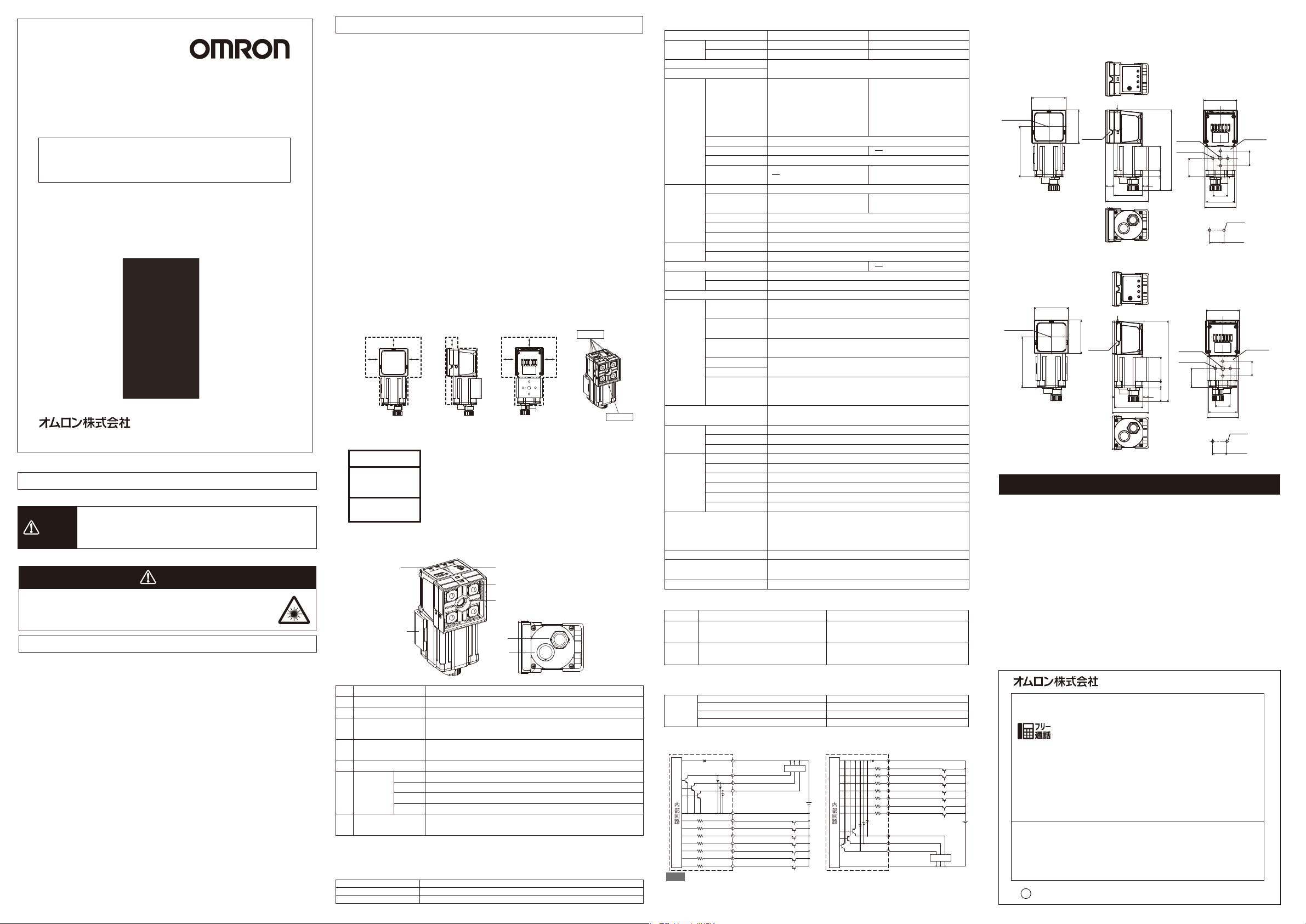
■外形寸法図
(単位:mm)
*取付金具(背面取付)、偏光フィルタアタッチメントありの寸法図を示す。
形FQ-CR□□010F-M/FQ-CR□□050F-M
光軸
46
45
ポラライザ
67
1
1/4-20UNC
深さ6
4-M4深さ6
(108)
32
918
11
(57)
8
38
(25)
44
20
38
42
取付穴加工寸法
2-φ4.5
20±0.1
締付けトルク:1.2N・m
取付金具
形FQ-CR□□100F-M/FQ-CR□□100N-M
光軸
46
1
45
ポラライザ
67
3
38
(49)
1/4-20UNC
深さ6
4-M4深さ6
(108)
32
918
8
(25)
44
20
38
42
取付穴加工寸法
2-φ4.5
20±0.1
締付けトルク:1.2N・m
取付金具
ご承諾事項
当社商品は、一般工業製品向けの汎用品として設計製造されています。従いまして、次に
掲げる用途での使用を意図しておらず、お客様が当社商品をこれらの用途に使用される際
には、当社は当社商品に対して一切保証をいたしません。ただし、次に掲げる用途であって
も当社の意図した特別な商品用途の場合や特別の合意がある場合は除きます。
(a)高い安全性が必要とされる用途(例:原子力制御設備、燃焼設備、航空・宇宙設備、鉄
道設備、昇降設備、娯楽設備、医用機器、安全装置、その他生命・身体に危険が及び
うる用途)
(b)高い信頼性が必要な用途(例:ガス・水道・電気等の供給システム、24時間連続運転
システム、決済システムほか権利・財産を取扱う用途など)
(c)厳しい条件または環境での用途(例:屋外に設置する設備、化学的汚染を被る設備、
電磁的妨害を被る設備、振動・衝撃を受ける設備など)
(d)カタログ等に記載のない条件や環境での用途
*(a)から(d)に記載されている他、本カタログ等記載の商品は自動車(二輪車含む。以下同
じ)向けではありません。自動車に搭載する用途には利用しないで下さい。自動車搭載
用商品については当社営業担当者にご相談ください。
*上記は適合用途の条件の一部です。当社のベスト、総合カタログ、データシート等最新版
のカタログ、マニュアルに記載の保証・免責事項の内容をよく読んでご使用ください。
インダストリアルオートメーションビジネスカンパ ニー
●製品に関するお問い合わせ先
お客様相談室
クイック オムロン
0120-919-066
携帯電話・PHS・IP電話などではご利用いただけませんので、下記の電話番号へおかけください。
電話
055-982-5015
■営業時間:8:00〜21:00 ■営業日:365日
●FAXやWebページでもお問い合わせいただけます。
FAX055-982-5051/www.fa.omron.co.jp
●その他のお問い合わせ
納期・価格・サンプル・仕様書は貴社のお取引先、または貴社
担当オムロン販売員にご相談ください。
オムロン制御機器販売店やオムロン販売拠点は、Webページで
ご案内しています。
v
A
2014年7月
(通話料がかかります)
20
20
Page 2
Model
FQ-CR
□
Fixed Mount Code Reader
INSTRUCTION SHEET
Thank you for selecting OMRON product. This sheet primarily describes precautions required in installing and
operating the product.
Before operating the product, read the sheet thoroughly to
acquire sufficient knowledge of the product. For your convenience, keep the sheet at your disposal.
TRACEABILITY INFORMATION:
Importer in EU:
Omron Europe B.V.
Wegalaan 67-69
2132 JD Hoofddorp,
The Netherlands
The following notice applies only to products that carry the CE mark:
Notice:
This is a class A product. In residential areas it may cause radio
interference, in which case the user may be required to take adequate
measures to reduce interference.
・Regulation of KC marking
이 기기는 업무용 환경에서 사용할 목적으로 적합성평가를 받은 기기로서 가정용 환경에서
사용하는 경우 전파간섭의 우려가 있습니다.
OMRON Corporation All Rights Reserved.
©
SAFETY PRECAUTIONS
●Keys to Warning Symbols
WARNING
●Warning Symbols
The Sensor emits visible light which may on rare occasions
have a harmful effect on the eyes. Do not look directly at the
light emitted by the sensor. If the light projects onto a reflective
surface, prevent the reflected light from entering a person's
eyes.
Precautions for Safe Use
Always follow the rules below to ensure safety.
1. Installation environment
· Do not use in a location where there is flammable or explosive gas.
· To ensure safe operation and maintenance, install away from high-voltage equipment and power equipment.
· Tighten the mounting screws to the torque specified in these instructions.
2. Power and cable connections
· Always turn off the power of the unit before connecting or disconnecting cables.
· Do not reverse the polarity of the power connection. Do not short the load of the open collector output.
· Wire this product separately from the wiring of high-voltage wires and power wires. If wired together or in
the same conduit, induction may occur and cause malfunctioning or damage.
· Use a load that is equal to or less than the rating.
· Use the specified power voltage.
· Use the specified size of crimp terminals for wiring connections. Do not connect wires that have been
simply twisted together directly to the power supply or terminal block.
· Supply power from a DC power supply for which measures have been applied to prevent high voltages
(e.g., a safety extra low voltage circuit).
· If UL certification is required for the overall system, use a UL Class II DC power supply.
· Use an independent power source for this product. Do not use a shared power source.
3. Handling
· Do not peel off or damage the waterproof sheet attached to the side of the unit. Doing so may result in dirt,
dust or water droplet entering inside the device, causing a failure of the unit.
· Always attach the covers of I/O cable connector and Ethernet cable connector. This prevents extraneous
material from making a failure of the sensor.
4. Other Rules
· Do not use in safety circuits for atomic energy or that are critical for human life.
· Do not attempt to disassemble, deform by pressure, incinerate, repair, or modify this product.
· Use the dedicated touch finder (FQ□-D), cable (FQ-WN, FQ-WD) . Sensor malfunction or damage may
occur if any other devices or cables are used.
· When disposing of the product, treat as industrial waste.
· If you notice an abnormal condition such as a strange odor, extreme heating of the unit, or smoke,
immediately stop using the product, turn off the power, and consult your dealer .
· The device surface becomes hot during use. Do not touch.
Manufacturer:
Omron Corporation,
Shiokoji Horikawa, Shimogyo-ku,
Kyoto 600-8530 JAPAN
2012-2015
Indicates a potentially hazardous situation which, if
not avoided, could result in death or serious injury.
Additionally, there may be severe property damage.
WARNING
Precautions for Correct Use
Observe the following to prevent failure, malfunctioning, and adverse effects on performance and
the device.
1. Installation site
· Do not install in the following locations:
· Locations where the ambient temperature exceeds the rated temperature range.
· Locations subject to sudden temperature changes (where condensation will form).
· Locations where the relative humidity is below or above 35 to 85% RH.
· Locations where there are corrosive or flammable gases.
· Locations where there is dust, salt, or iron powder.
· Locations where the device will be subject to direct vibration or shock.
· Locations where there is strong scattered light (laser light, arc welding light, ultraviolet light, etc.)
· Locations exposed to direct sunlight or next to a heater.
· Locations where there is splashing or spraying of water, oil, or chemicals.
· Locations where there is a strong electrical or magnetic field.
2. Power and cable connections
· When using a switching regulator, ground the FG pin of the switching regulator.
·
If there are surges on your power line, connect a surge absorber as appropriate for your conditions of use.
· Before turning on the power after the wiring is completed, verify that the power is correct, that
there are no incorrect connections such as a shorted load circuit, and that the load current is
suitable. Incorrect wiring may cause damage and failures.
3. Optical axis and detection range
There is a certain amount of deviation among sensors in the center of the optical axis. For this
reason, when installing the sensor, be sure to check the center of the image and the detection
range in the LCD monitor of the Touch Finder and in the sensor software.
4. Focus adjustment knob
Do not turn the focus adjustment knob to higher than 0.1 N·m. This may cause damage.
5. Maintenance and inspection
· Do not use thinner, alcohol, benzene, acetone, or kerosene to clean the sensor or Touch Finder.
·
If considerable foreign matter or dust collects on the panel on the front of the senor, use a blower
brush (for camera lenses) to blow off the foreign matter. Avoid blowing it off with your breath.
· For a small amount of foreign matter or dust, gently wipe with a soft cloth. Do not wipe hard.
If the surface is damaged, false detection may result.
6. Defective pixel
· It is neither a defect of the product nor a breakdown though two or more defective pixels might
beincluded in this product by the specification of CMOS image sensor.
7. Installation of camera
· In the environment with high humidity and intense temperature change, the inside of a front
plate might uncommonly become cloudy.
· Do not install an object (except for the dedicated mounting bracket) inside the dotted areas
shown on the under figures. Doing so may result in fogging inside the front plate.
25mm 25mm
25mm 25mm
25mm 25mm
25mm
■ Safety of LED
The product is considered to be classified as Risk Group 2 by IEC62471.
CAUTION
Possibly hazardous
optical radiation emitted
from this product
Risk Group 2
IEC 62471
■ Part Names and Functions
(6)
(7)
DescriptionNameNo.
(1)
Lighting
(2)
Camera lens
I/O Cable connector
(3)
(4)
Ethernet cable
connector
(5)
Focus adjustment screw
(6)
Operation
indicators
(7)
Mounting Bracket
OR
ETN
ERROR
BUSY
LEDs for illumination are mounted here.
Lens with a focus feature.
An I/O Cable is used to connect the Sensor to the power supply
and external devices. Dedicated I/O cable: FQ-WD
An Ethernet cable is used to connect the Sensor to the Touch
Finder or a computer. Dedicated Ethernet cable: FQ-WN
Used to adjust the focus of the image.
Lights orange when the total judgment output (OR) signal is ON.
Lights orange during communication by Ethernet.
Lights red when an error occurs.
Lights green while the sensor is operating.
Used to secure the Sensor in place.
The Mounting Bracket can be attached to the front, left
side, right side, or back of the Sensor.
■
Power connection(when a switching regulator is connected)
The following power supply is recommended (option)
Item
Recommended Power Supply
External power supply terminal screws
(5)
(1)
(2)
(4)
(3)
Description
S8VS-06024 (OMRON 24VDC 2.5A)
M4 (tightening torque: 1.2 N·m)
Waterproofsheet
Waterproofsheet
■ Ratings/Performance
Item
Model
Field of view/installation distance
Main
functions
Image input
Illumination
Auxiliary Functions
Data logging
Measurement trigger
I/O
specifications
Indicator
Ratings
Environmental
immunity
Materials
Weight
Accessories
LED Safety
*1. The three output signals can be allocated for the judgments of individual inspection items.
*2. The following table gives the I/O specifications.
Input
specifications
Output
specifications
*3. All scene may not be possible to be registered according to some settings.
●Connection with external devices
Use only the dedicated external connecting devices.
Dedicated external
connecting device
NPN
PNP
Inspection items
Number of simultaneous inspections
Position compensation
Number of registered scenes *3
Retry function
Image processing method
Image filter
Image elements
Shutter
Processing resolution
Partial capture function
Illumination method
Illumination color
Measurement data
Images
Input signals
Output signals
Ethernet specifications
Input specifications
Output specifications
Connection method
Power supply voltage
Insulation resistance
Current consumption
Ambient temperature range
Ambient humidity range
Ambient atmosphere
Vibration resistance(destructive)
Shock resistance (destructive)
Degree of protection
ON: Shorted to 0 V, or 1.5 V max.
OFF: Open (leakage current: 0.1 mA max.)
NPN open collector
30 VDC, 50 mA max., residual voltage: 1.2 V max.
FQ□-D□□
FQ-WD□□□
FQ-WN□□□
■ Input signal circuit diagram
NPN type
Internal circuit
Important
Measures to prevent chattering
Although the sensor has a chatter prevention function, an incorrect input by chattering cannot be prevented when chattering
·
of 100 μs or more occurs. (An input signal of less than 100 μs is ignored, and 100 μs or more is judged as an input signal.)
· Be sure to use a non-contact relay (SSR, PLC transistor output) for input signals. Using a relay with contacts
may allow for additional trigger inputs during measurement due to a bound of the contacts.
Brown Power supply(24VDC)
Black
Orange OUT1(BUSY)
Light Blue
Blue GND(0V
Pink TRIG
Gray IN0
Green IN1
Red IN2
White IN3
Purple IN4
Yellow IN5
Fixed Mount Multi Code Reader
FQ-CR10□□□□-M
FQ-CR15□□□□-M
Refer to the optical diagram (listed in the User's Manual).
Bar code (JAN/EAN/UPC, Code39, Codabar (NW-7), ITF
(Interleaved 2 of 5), Code 93, Code128/GS1-128, GS1 DataBar*
(Truncated, Stacked, Omni-directional, Stacked Omni-directional,
Limited, Expanded, Expanded Stacked), Pharmacode, GS1-128
Composite Code (CC-A, CC-B, CC-C)),
2D code (Data Matrix (EC200), QR Code, MicroQR Code,
PDF417, MicroPDF417
32
Supported (Correcting rotational position and edge position)
32
Monochrome
High dynamic range (HDR)
polarizing filter (attachment)
1/3-inch monochrome CMOS
1/250〜1/32258 (sec)
752(H) x 480(V)
Available (horizontal and vertical directions)
Pulse illumination
White
Operations (four arithmetic operations, enumeration function,
trigonometric function, logic function)
In Sensor: 1,000 items (If a Touch Finder is used, results can be saved up to the capacity of an SD card.)
In Sensor: 20 images (If a Touch Finder is used, images can be saved up to the capacity of an SD card.)
External trigger (single or continuous),
7 signals: Single measurement input (TRIG),
Control Command Input (IN0 to IN5)
3 signals *1: Control output (BUSY), overall judgment output (OR),
error output (ERROR)
100Base-TX/10Base-T Numerical output, control command compatible
(Non-procedural communications)
Refer to *2.
Special connector cables
For power supply, I/O : 1 (FQ-WD□□□)
Touch Finder and computer: 1 cable (FQ-WN□□□)
BUSY indicator (BUSY/green), Judgment results indicator (OR/orange),
ERROR indicator (ERROR/red), Ethernet communication indicator(ETN/orange)
21.6 to 26.4 VDC (including ripple)
Between all lead wires and case: 0.5 MΩ (at 250 V)
2.4A MAX
Operating: 0 to 50°C Storage: -25 to 65°C (no icing or condensation)
Operating and storage: 35% to 85% (with no condensation)
No corrosive gas
10 to 150 Hz, single amplitude: 0.35 mm in 3 directions (X, Y and Z), 10 sweeps each (8 min/sweep)
150m/s2 3 times each in 6 directions (up/down, left/right, forward/backward)
IEC 60529 IP67(except when the polarizing filter attachment is mounted or connector cap is removed.)
Sensor: PBT,PC,SUS Mounting bracket: PBT,brass,sponge rubber(EPDM)
Deflection filter attachment: PBT, PC
Ethernet connector: Oil resistant vinyl compound I/O connector: Lead free heat resistant PVC
200 g max.
· Mounting bracket (FQ-XL) x1
· Deflection filter attachment (FQ-XF1) x1
· Instruction manual (This Instruction Sheet)
· SYSMAC membership registration sheet
Risk Group 2 (IEC62471)
NPN
Model
ON: Shorted to power supply voltage, or power supply voltage -1.5 V max.
OFF: Open (leakage current: 0.1 mA max.)
PNP open collector
30 VDC, 50 mA max., residual voltage: 1.2 V max.
PNP type
Load
OUT0(OR)
OUT2(ERROR)
24 VDC
)
Internal circuit
Fixed Mount 2D Code Reader
FQ-CR20□□□□-M
FQ-CR25□□□□-M
2D code (compatible code:
Data Matrix ECC200 from 10 x
10 to 64 x 64, 8 x 18 to 16 x
48, QR Code model 1 and 2
from 21 x 21 to 57 x 57
(version 1 to 10)
Simple retry, brightness fluctuation retry, scene
switch retry, level trigger retry
High dynamic range (HDR) polarizing filter
(attachment), and smoothing, expansion,
reduction, median
PNPItem
Touch finder
I/O cable
Ethernet cable
Name
Brown Power supply(24VDC)
Pink TRIG
Gray IN0
Green IN1
Red IN2
White IN3
Purple IN4
Yellow IN5
Light Blue
OUT2(ERROR)
Orange
OUT1(BUSY)
Black
Black OUT0(OR)
Blue GND(0V)
24 VDC
Load
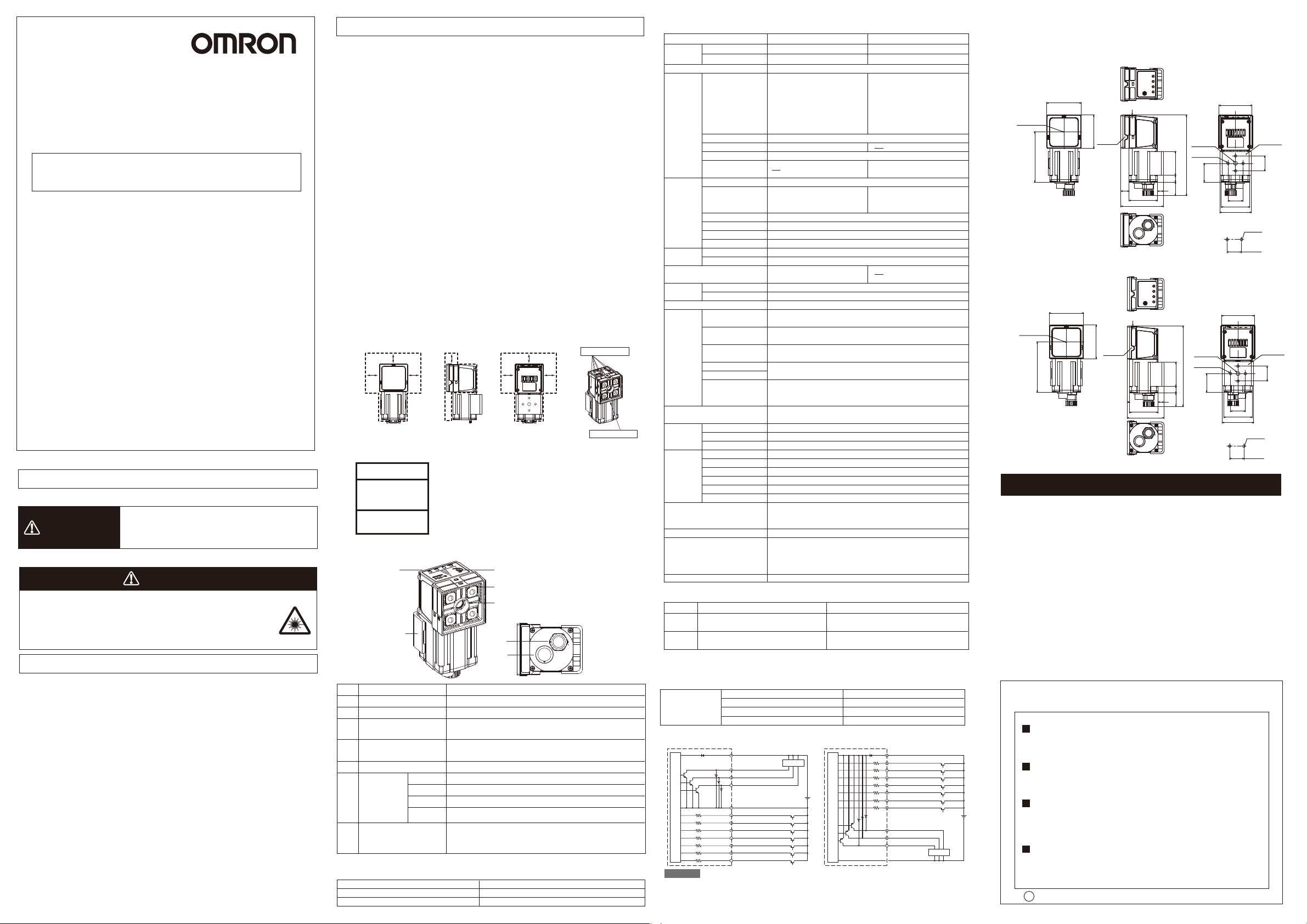
■ Dimensions
* Dimension diagram with mounting bracket (rear-side attachment) and polarizing filter
attachment is shown.
FQ-CR□□010F-M/FQ-CR□□050F-M
Beam
46
45
Polarizer
67
1
1/4-20UNC
Depth6
4-M4Depth6
(108)
32
(25)
918
11
(57)
8
38
FQ-CR□□100F-M/FQ-CR□□100N-M
46
1
Beam
67
45
Polarizer
1/4-20UNC
Depth6
4-M4Depth6
(108)
32
(25)
918
3
8
38
(49)
Suitability for Use
Omron Companies shall not be responsible for conformity with any standards,
codes or regulations which apply to the combination of the Product in the
Buyer’s application or use of the Product. At Buyer’s request, Omron will
provide applicable third party certification documents identifying ratings and
limitations of use which apply to the Product. This information by itself is not
sufficient for a complete determination of the suitability of the Product in
combination with the end product, machine, system, or other application or
use. Buyer shall be solely responsible for determining appropriateness of the
particular Product with respect to Buyer’s application, product or system.
Buyer shall take application responsibility in all cases.
NEVER USE THE PRODUCT FOR AN APPLICATION INVOLVING
SERIOUS RISK TO LIFE OR PROPERTY WITHOUT ENSURING THAT THE
SYSTEM AS A WHOLE HAS BEEN DESIGNED TO ADDRESS THE RISKS,
AND THAT THE OMRON PRODUCT(S) IS PROPERLY RATED AND
INSTALLED FOR THE INTENDED USE WITHIN THE OVERALL
EQUIPMENT OR SYSTEM.
See also Product catalog for Warranty and Limitation of Liability.
OMRON Corporation
Tokyo, JAPAN
Regional Headquarters
OMRON EUROPE B.V.
Sensor Business Unit
Carl-Benz-Str. 4, D-71154 Nufringen, Germany
Tel: (49) 7032-811-0/Fax: (49) 7032-811-199
OMRON ELECTRONICS LLC
2895 Greenspoint Parkway, Suite 200
Hoffman Estates, IL 60169 U.S.A.
Tel: (1) 847-843-7900/Fax: (1) 847-843-7787
OMRON ASIA PACIFIC PTE. LTD.
No. 438A Alexandra Road # 05-05/08 (Lobby 2),
Alexandra T echnopark,
Singapore 119967
Tel: (65) 6835-3011/Fax: (65) 6835-2711
OMRON (CHINA) CO., LTD.
Room 2211, Bank of China Tower,
200 Yin Cheng Zhong Road,
PuDong New Area, Shanghai, 200120, China
Tel: (86) 21-5037-2222/Fax: (86) 21-5037-2200
s
Oct, 2014
D
Industrial Automation Company
Contact: www.ia.omron.com
(Unit: mm)
44
Mounting
bracket
20
20
38
42
Mountingholedimensions
2-4.5Dia.
20±0.1
Tighteningtorque:1.2N×m
44
Mounting
bracket
20
20
38
42
Mountingholedimensions
2-4.5Dia.
20±0.1
Tighteningtorque:1.2N×m
 Loading...