

Page 1

Cat. No. Z302-E1-0$
ZX-T Series
FQ
Vision Sensor
USERS MANUAL
Page 2

Page 3

Introduction
Thank you for purchasing the FQ.
This manual provides information regarding functions, performance and operating methods that
are required for using the FQ.
When using the FQ, be sure to observe the following:
• The FQ must be operated by personnel knowledgeable in electrical engineering.
• To ensure correct use, please read this manual thoroughly to deepen your understanding of the
product.
• Please keep this manual in a safe place so that it can be referred to whenever necessary.
Page 4

Page 5

APPLICATION CONSIDERATIONS
(Please Read)
1
User's Manual
Introduction
Installation and Connections
Taking Images
Setting Up Inspections
Testing and Saving Settings
Operation
1
2
3
4
5
6
Vision Sensor
FQ
Convenient Functions
Communications with External Devices
Troubleshooting
Appendices
7
8
9
10
Page 6

READ AND UNDERSTAND THIS DOCUMENT
Please read and understand this document before using the products. Please consult your OMRON
representative if you have any questions or comments.
WARRANTY
OMRON’s exclusive warranty is that the products are free from defects in materials and workmanship for a
period of one year (or other period if specified) from date of sale by OMRON.
OMRON MAKES NO WARRANTY OR REPRESENTATION, EXPRESS OR IMPLIED, REGARDING NONINFRINGEMENT, MERCHANTABILITY, OR FITNESS FOR PARTICULAR PURPOSE OF THE PRODUCTS.
ANY BUYER OR USER ACKNOWLEDGES THAT THE BUYER OR USER ALONE HAS DETERMINED THAT
THE PRODUCTS WILL SUITABLY MEET THE REQUIREMENTS OF THEIR INTENDED USE. OMRON
DISCLAIMS ALL OTHER WARRANTIES, EXPRESS OR IMPLIED.
LIMITATIONS OF LIABILITY
OMRON SHALL NOT BE RESPONSIBLE FOR SPECIAL, INDIRECT, OR CONSEQUENTIAL DAMAGES,
LOSS OF PROFITS OR COMMERCIAL LOSS IN ANY WAY CONNECTED WITH THE PRODUCTS,
WHETHER SUCH CLAIM IS BASED ON CONTRACT, WARRANTY, NEGLIGENCE, OR STRICT LIABILITY.
In no event shall responsibility of OMRON for any act exceed the individual price of the product on which
liability is asserted.
IN NO EVENT SHALL OMRON BE RESPONSIBLE FOR WARRANTY, REPAIR, OR OTHER CLAIMS
REGARDING THE PRODUCTS UNLESS OMRON’S ANALYSIS CONFIRMS THAT THE PRODUCTS WERE
PROPERLY HANDLED, STORED, INSTALLED, AND MAINTAINED AND NOT SUBJECT TO
CONTAMINATION, ABUSE, MISUSE, OR INAPPROPRIATE MODIFICATION OR REPAIR.
SUITABILITY FOR USE
THE PRODUCTS CONTAINED IN THIS DOCUMENT ARE NOT SAFETY RATED. THEY ARE NOT DESIGNED OR
RATED FOR ENSURING SAFETY OF PERSONS, AND SHOULD NOT BE RELIED UPON AS A SAFETY COMPONENT OR PROTECTIVE DEVICE FOR SUCH PURPOSES.
Please refer to separate catalogs for OMRON’s safety rated products.
OMRON shall not be responsible for conformity with any standards, codes, or regulations that apply to the
combination of products in the customer’s application or use of the product.
At the customer’s request, OMRON will provide applicable third party certification documents identifying ratings
and limitations of use that apply to the products. This information by itself is not sufficient for a complete
determination of the suitability of the products in combination with the end product, machine, system, or other
application or use.
The following are some examples of applications for which particular attention must be given. This is not
intended to be an exhaustive list of all possible uses of the products, nor is it intended to imply that the uses
listed may be suitable for the products:
• Outdoor use, uses involving potential chemical contamination or electrical interference, or conditions or
uses not described in this document.
2
FQ User’s Manual
Page 7

• Nuclear energy control systems, combustion systems, railroad systems, aviation systems, medical
equipment, amusement machines, vehicles, safety equipment, and installations subject to separate industry
or government regulations.
• Systems, machines, and equipment that could present a risk to life or property.
Please know and observe all prohibitions of use applicable to the products.
NEVER USE THE PRODUCTS FOR AN APPLICATION INVOLVING SERIOUS RISK TO LIFE OR
PROPERTY WITHOUT ENSURING THAT THE SYSTEM AS A WHOLE HAS BEEN DESIGNED TO
ADDRESS THE RISKS, AND THAT THE OMRON PRODUCT IS PROPERLY RATED AND INSTALLED FOR
THE INTENDED USE WITHIN THE OVERALL EQUIPMENT OR SYSTEM.
PERFORMANCE DATA
Performance data given in this document is provided as a guide for the user in determining suitability and does
not constitute a warranty. It may represent the result of OMRON’s test conditions, and the users must correlate
it to actual application requirements. Actual performance is subject to the OMRON Warranty and Limitations of
Liability.
CHANGE IN SPECIFICATIONS
Product specifications and accessories may be changed at any time based on improvements and other
reasons.
It is our practice to change model numbers when published ratings or features are changed, or when significant
construction changes are made. However, some specifications of the product may be changed without any
notice. When in doubt, special model numbers may be assigned to fix or establish key specifications for your
application on your request. Please consult with your OMRON representative at any time to confirm actual
specifications of purchased products.
DIMENSIONS AND WEIGHTS
Dimensions and weights are nominal and are not to be used for manufacturing purposes, even when
tolerances are shown.
ERRORS AND OMISSIONS
The information in this document has been carefully checked and is believed to be accurate; however, no
responsibility is assumed for clerical, typographical, or proofreading errors, or omissions.
PROGRAMMABLE PRODUCTS
OMRON shall not be responsible for the user’s programming of a programmable product, or any consequence
thereof.
COPYRIGHT AND COPY PERMISSION
This document shall not be copied for sales or promotions without permission.
This document is protected by copyright and is intended solely for use in conjunction with the product. Please
notify us before copying or reproducing this document in any manner, for any other purpose. If copying or
transmitting this document to another, please copy or transmit it in its entirety.
FQ User’s Manual
3
Page 8
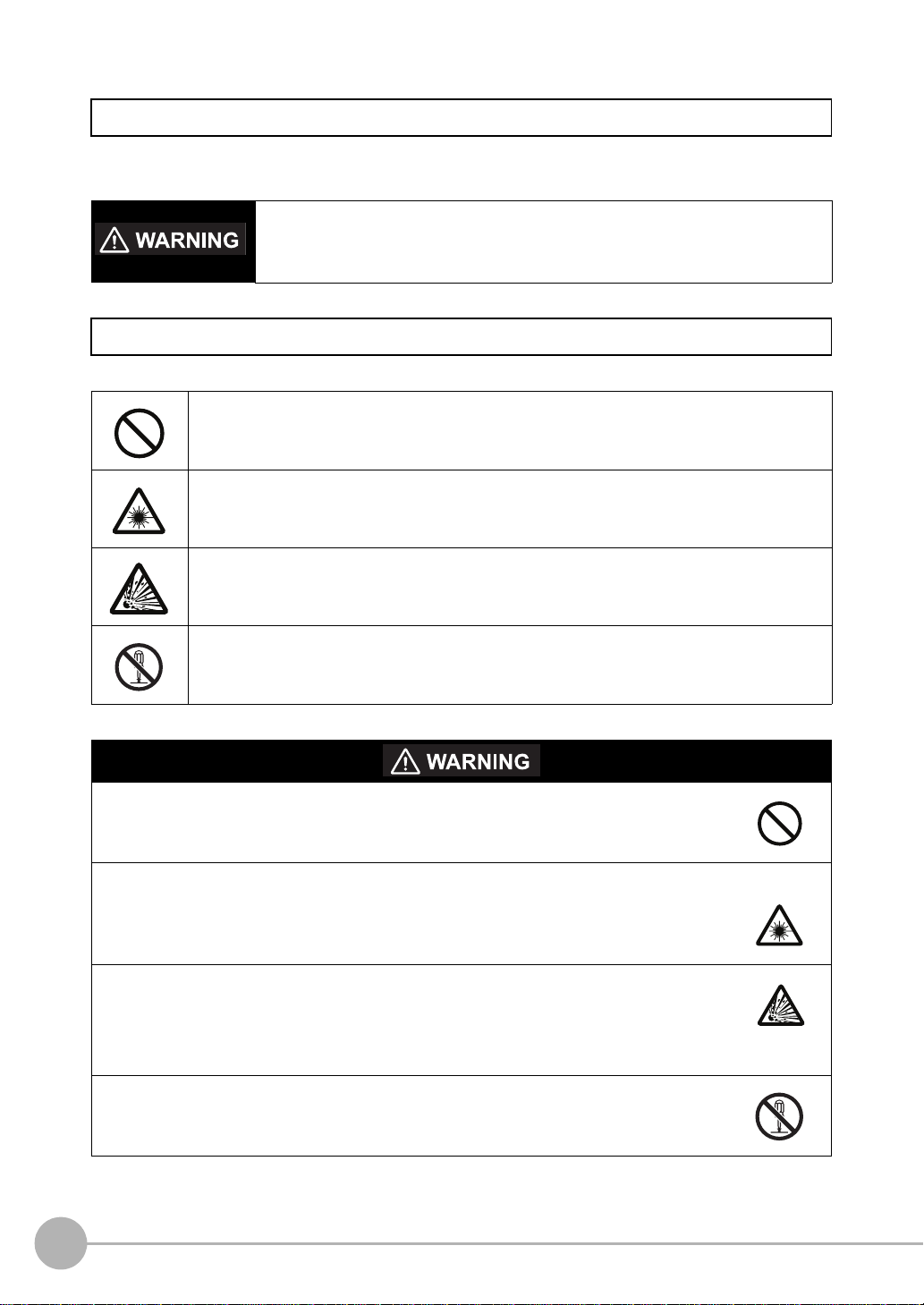
Meanings of Signal Words
The following signal words are used in this manual.
Indicates a potentially hazardous situation which, if not avoided, will result in minor or
moderate injury, or may result in serious injury or death. Additionally there may be
significant property damage.
Meanings of Alert Symbols
The following alert symbols are used in this manual
Indicates general prohibitions for which there is no specific symbol.
Indicates the possibility of laser radiation.
Indicates the possibility of explosion under specific conditions.
Indicates prohibition when there is a risk of minor injury from electrical shock or other
source if the product is disassembled.
This product is not designed or rated for ensuring safety of persons.
Do not use it for such purposes.
The Sensor emits visible light, which may adversely affect the eyes in rare instances.
Do not look directly into the light emitted from the Sensor. When the subject is a specular
reflective object, protect your eyes from reflected light.
A lithium ion battery is built into the Touch Finder and may occasionally combust, explode, or
burn if not treated properly.
Dispose of the Touch Finder as industrial waste, and never disassemble, apply pressure that
would deform, heat to 100 °C or higher, or incinerate the Touch Finder.
High-voltage parts inside; danger of electrical shock. Do not open the product cover.
4
FQ User’s Manual
Page 9

Precautions for Safe Use
The following points are important to ensure safety, so make sure that they are strictly observed.
1. Installation Environment
• Do not use the product in environments where it can be exposed to inflammable/explosive gas.
• To secure the safety of operation and maintenance, do not install the product close to high-voltage devices
and power devices.
• Install the product in such a way that its ventilation holes are not blocked.
• Tighten mounting screws at the torque specified in this manual.
2. Power Supply and Wiring
• The power supply voltage must be within the rated range (24 VDC ±10%), and an AC voltage must not be
used.
• Reverse connection of the power supply is not allowed. Do not short the load of the open collector output.
• The load must be within the rated range.
• High-voltage lines and power lines must be wired separately from this product. Wiring them together or
placing them in the same duct may cause induction, resulting in malfunction or damage.
• Use the products within the power supply voltages specified in this manual.
• Use the specified size of crimp terminals to wire connections. Do not connect wires that have been simply
twisted together directly to the power supply or terminal block.
• Use a DC power supply with safety measures against high voltages (safety extra low-voltage circuit).
• Use independent power sources for the products. Do not use a shared power source.
• Tighten mounting screws at the torque specified in this manual.
• Always turn OFF the power supply before connecting or disconnecting cables or the power supply wiring.
3. Battery
• Do not short the positive and negative terminals of the Battery.
• Do not use the Touch Finder in an environment that exceeds the operating temperature range of the Battery.
If the Touch Finder is used at temperatures that exceed the operating temperature range, the protective
device may activate and prevent charging.
• Do not connect the Battery directly to a power supply or car cigarette lighter socket.
• Do not use the Touch Finder with any other type of battery.
• Turn OFF the power supply immediately if the Battery leaks or produces an odor. Electrolyte leaked from the
Battery may ignite, possibly causing smoke, rupture, or fire.
• If during usage, charging, or storage, the Battery produces an odor, heats, becomes discolored, becomes
misshapen, or exhibits any other unusual conditions, remove it and do not use it. Continuing to use such a
Battery may result in the Battery heating, smoking, rupturing, or igniting.
• If the Touch Finder (FQ-D31) will be installed permanently or semi-permanently, remove the Battery (FQ-
BAT1). If the rated temperature is exceeded with the Battery inserted, the protective circuit may activate and
stop the Touch Finder.
4. AC Adapter
• Use an AC cable that is suitable for the power supply and power voltage you are using.
• Do not touch the power plug with a wet hand. Doing so may result in electrical shock.
• If you notice an abnormal condition, such as smoke, abnormal heating of the outer surface, or a strange
odor, immediately stop using the AC Adapter, turn OFF the power, and remove the power plug from the
outlet.
Consult your dealer, as it is dangerous to attempt to repair the AC Adapter yourself.
• If the AC Adapter is dropped or damaged, turn OFF the power, remove the power plug from the outlet, and
contact your dealer. There is a risk of fire if you continue using the AC Adapter.
FQ User’s Manual
5
Page 10

5. Other
• Do not use this product in safety circuits associated with nuclear power and human life.
• Do not disassemble, repair, modify, deform by pressure, or incinerate this product.
• Dispose of this product as industrial waste.
• Connect the special products (Sensor, Touch Finder, Cables). The product might break down or malfunction
if you use a part not included in the special products.
• If you notice an abnormal condition, such as a strange odor, extreme heating of any product, or smoke,
immediately stop using the product, turn OFF the power, and consult your dealer.
• The Sensor surfaces become hot during use. Do not touch them.
• Do not drop or subject the products to shock.
• Use the special Sensor (FQ-S), Touch Finder (FQ-D), Cables (FQ-WN and FQ-WD), Battery (FQ-BAT1),
and AC Adapter (FQ-AC). Using other than the specified products may cause fire, burning, malfunction or
failure.
• If the product has a lock mechanism, always make sure it is locked before using the product.
6. Laws and Regulations, Standards
• This product complies with the following EC Directives and EN Standards:
EC Directive No.2004/104/EC
EN Standards EN61326
6
FQ User’s Manual
Page 11

Precautions for Correct Use
Observe the following precautions to prevent failure to operate, malfunctions, or undesirable effects on product
performance.
1. Installation Site
Do not install this product in locations subjected to the following conditions:
• Ambient temperature outside the rating
• Rapid temperature fluctuations (causing condensation)
• Relative humidity outside the range of 35 to 85%
• Direct vibration or shock
• Strong ambient light (such as other laser beams, light from arc-welding machines, or ultraviolet light)
• Direct sunlight or near heaters
• Strong magnetic or electric field
Also, do not install this product in locations subjected to the following conditions to ensure its protective
performance as described in the specifications:
• Presence of corrosive or flammable gases
• Presence of dust, salt, or iron particles
• Water, oil, or chemical fumes or spray, or mist atmospheres
2. Power Supply, Connection, and Wiring
• When using a commercially available switching regulator, make sure that the FG terminal is grounded.
• If surge currents are present in the power lines, connect surge absorbers that suit the operating
environment.
• Before turning ON the power after the product is connected, make sure that the power supply voltage is
correct, there are no incorrect connections (e.g. load short-circuit) and the load current is appropriate.
Incorrect wiring may result in breakdown of the product.
• For cables, use only the special products specified in this manual.
p.154, p.155
• Use only combinations of the Sensor and Touch Finder specified in this manual. Using other combinations
may cause malfunction or damage.
• Do not turn the power OFF in the following instances. Doing so will damage data that is in the process of
being saved.
- While data is being saved in internal memory
- While data is being saved on the SD card
• The LCD panel has been made using precision technology, and sometimes a few pixels are missing in the
panel. This is due to the structure of the LCD panel, and is not a malfunction.
• Connector cover
Always attach the covers of I/O cable connector and Ethernet cable connector. This prevents extraneous
material from making malfunction of the Sensor.
3. Battery
• Do not use or charge the Battery with other than the specified products.
• Do not charge the Battery with other than the specified AC adapter.
• When using the Touch Finder, the battery cover screw must be tightened.
4. AC Adapter
• During maintenance and when not using the Touch Finder for an extended time, remove the power plug
from the outlet.
• Do not bend the power cable past its natural bending radius.
• Do not use the AC Adapter with other than the specified products.
• If a voltage higher than 380 V is applied, there is a risk that the capacitor will be damaged, the pressure
valve will open, and vaporized gas will be emitted. If there is a possibility that a voltage higher than 380 V
will be applied, use a protective device.
FQ User’s Manual
7
Page 12

5. Maintenance and Inspection
Do not use thinner, benzene, acetone or kerosene to clean the Sensor and Touch Finder. If large dust particles
adhere to the Camera, use a blower brush (used to clean camera lenses) to blow them off. Do not use breath
from your mouth to blow the dust off. To remove dust particles from the Camera, wipe gently with a soft cloth
(for cleaning lenses) moistened with a small amount of alcohol. Do not use excessive force to wipe off dust
particles. Scratches to the Camera might cause error.
Editor's Note
■ Meaning of Symbols
Menu items that are displayed on the Touch Finder LCD screen, and windows, dialog boxes and other GUI
elements displayed on the PC are indicated enclosed by brackets "[ ]".
■ Visual Aids
Important
Indicates points that are important to achieve the full product performance,
such as operational precautions.
Note
Indicates application procedures.
Indicates pages where related information can be found.
8
FQ User’s Manual
Page 13

Table of Contents
1. Introduction
1-1 FQ-series Vision Sensors. . . . . . . . . . . . . . . . . . . . . . . . . . . . . . . . . . . . . . 14
1-2 Measurement Process . . . . . . . . . . . . . . . . . . . . . . . . . . . . . . . . . . . . . . . . 15
1-3 Startup Display and Display Elements . . . . . . . . . . . . . . . . . . . . . . . . . . . 16
1-4 Basic Operational Flow. . . . . . . . . . . . . . . . . . . . . . . . . . . . . . . . . . . . . . . . 18
2. Installation and Connections
2-1 System Configuration. . . . . . . . . . . . . . . . . . . . . . . . . . . . . . . . . . . . . . . . . 20
2-2 Part Names and Functions. . . . . . . . . . . . . . . . . . . . . . . . . . . . . . . . . . . . . 21
2-3 Installation . . . . . . . . . . . . . . . . . . . . . . . . . . . . . . . . . . . . . . . . . . . . . . . . . . 23
2-4 Wiring . . . . . . . . . . . . . . . . . . . . . . . . . . . . . . . . . . . . . . . . . . . . . . . . . . . . . . 28
2-5 Setting Up Ethernet. . . . . . . . . . . . . . . . . . . . . . . . . . . . . . . . . . . . . . . . . . . 33
3. Taking Images
3-1 Selecting a Sensor for Configuration . . . . . . . . . . . . . . . . . . . . . . . . . . . . 36
3-2 Adjusting Image Quality . . . . . . . . . . . . . . . . . . . . . . . . . . . . . . . . . . . . . . . 37
3-3 Adjusting the Object Position . . . . . . . . . . . . . . . . . . . . . . . . . . . . . . . . . . 42
3-4 Preventing Mutual Interference of Multiple Sensors . . . . . . . . . . . . . . . . 46
Table of Contents
4. Setting Up Inspections
4-1 Inspection Item Selection Guide . . . . . . . . . . . . . . . . . . . . . . . . . . . . . . . . 48
4-2 Setup Procedure for Inspection Items . . . . . . . . . . . . . . . . . . . . . . . . . . . 49
4-3 Configuring Inspection Items. . . . . . . . . . . . . . . . . . . . . . . . . . . . . . . . . . . 50
4-4 Inspecting with the Search Inspection Item . . . . . . . . . . . . . . . . . . . . . . . 52
4-5 Inspecting with the Edge Position Inspection Item . . . . . . . . . . . . . . . . . 58
4-6 Inspecting with the Edge Width Inspection Item . . . . . . . . . . . . . . . . . . . 63
4-7 Inspecting with the Area Inspection Item . . . . . . . . . . . . . . . . . . . . . . . . . 66
4-8 Inspecting with Color Data Inspection Item . . . . . . . . . . . . . . . . . . . . . . . 70
FQ User’s Manual
9
Page 14

5. Testing and Saving Settings
5-1 Performing Test Measurements. . . . . . . . . . . . . . . . . . . . . . . . . . . . . . . . . 74
5-2 Shortening the Measurement Takt Time. . . . . . . . . . . . . . . . . . . . . . . . . . 76
5-3 Adjusting the Judgement Parameters. . . . . . . . . . . . . . . . . . . . . . . . . . . . 77
5-4 Checking a List of All Inspection Item Results . . . . . . . . . . . . . . . . . . . . 79
5-5 Saving Data to the Sensor . . . . . . . . . . . . . . . . . . . . . . . . . . . . . . . . . . . . . 80
6. Operation
6-1 Starting Operation. . . . . . . . . . . . . . . . . . . . . . . . . . . . . . . . . . . . . . . . . . . . 82
6-2 Configuring the Run Mode Display . . . . . . . . . . . . . . . . . . . . . . . . . . . . . . 84
6-3 Checking the Trend of Measurement Results with Graphs . . . . . . . . . . 86
6-4 Adjusting Judgement Parameters during Operation. . . . . . . . . . . . . . . . 89
7. Convenient Functions
7-1 Changing the Scene to Change the Line Process . . . . . . . . . . . . . . . . . . 92
7-2 Display Functions . . . . . . . . . . . . . . . . . . . . . . . . . . . . . . . . . . . . . . . . . . . . 94
7-3 Monitoring the Signal I/O Status . . . . . . . . . . . . . . . . . . . . . . . . . . . . . . . . 97
7-4 Logging Measurement Data and Image Data . . . . . . . . . . . . . . . . . . . . . . 98
7-5 Saving Sensor Settings . . . . . . . . . . . . . . . . . . . . . . . . . . . . . . . . . . . . . . 105
7-6 SD Card Operations . . . . . . . . . . . . . . . . . . . . . . . . . . . . . . . . . . . . . . . . . 106
7-7 Convenient Functions for Operation. . . . . . . . . . . . . . . . . . . . . . . . . . . . 108
7-8 Convenient Functions for Setup . . . . . . . . . . . . . . . . . . . . . . . . . . . . . . . 110
7-9 Functions Related to the System. . . . . . . . . . . . . . . . . . . . . . . . . . . . . . . 111
8. Communications with External Devices
8-1 Operation with Default Configuration . . . . . . . . . . . . . . . . . . . . . . . . . . . 114
8-2 Setting the Measurement Trigger . . . . . . . . . . . . . . . . . . . . . . . . . . . . . . 115
8-3 Setting the Outputs. . . . . . . . . . . . . . . . . . . . . . . . . . . . . . . . . . . . . . . . . . 119
8-4 Controlling the Sensor from an External Device . . . . . . . . . . . . . . . . . . 125
9. Troubleshooting
9-1 Error Table . . . . . . . . . . . . . . . . . . . . . . . . . . . . . . . . . . . . . . . . . . . . . . . . . 132
9-2 Basic Troubleshooting . . . . . . . . . . . . . . . . . . . . . . . . . . . . . . . . . . . . . . . 134
10
FQ User’s Manual
Page 15

10. Appendices
10-1 Menu Tables. . . . . . . . . . . . . . . . . . . . . . . . . . . . . . . . . . . . . . . . . . . . . . . . 136
10-2 Specifications and Dimensions . . . . . . . . . . . . . . . . . . . . . . . . . . . . . . . . 146
10-3 Updating the Software . . . . . . . . . . . . . . . . . . . . . . . . . . . . . . . . . . . . . . . 156
10-4 LED Safety . . . . . . . . . . . . . . . . . . . . . . . . . . . . . . . . . . . . . . . . . . . . . . . . . 157
10-5 Requirements from Regulations and Standards . . . . . . . . . . . . . . . . . . 158
Index. . . . . . . . . . . . . . . . . . . . . . . . . . . . . . . . . . . . . . . . . . . . . . . . . . . . . . 162
Version Upgrade Information. . . . . . . . . . . . . . . . . . . . . . . . . . . . . . . . . . 167
Revision History . . . . . . . . . . . . . . . . . . . . . . . . . . . . . . . . . . . . . . . . . . . . 168
FQ User’s Manual
11
Page 16

12
FQ User’s Manual
Page 17

Introduction
1-1 FQ-series Vision Sensors . . . . . . . . . . . . . . . . . . . . . . . . . . . . . . . . . . .14
1-2 Measurement Process . . . . . . . . . . . . . . . . . . . . . . . . . . . . . . . . . . . . . .15
1-3 Startup Display and Display Elements . . . . . . . . . . . . . . . . . . . . . . . . .16
1-4 Basic Operational Flow . . . . . . . . . . . . . . . . . . . . . . . . . . . . . . . . . . . . .18
1
Introduction
Page 18
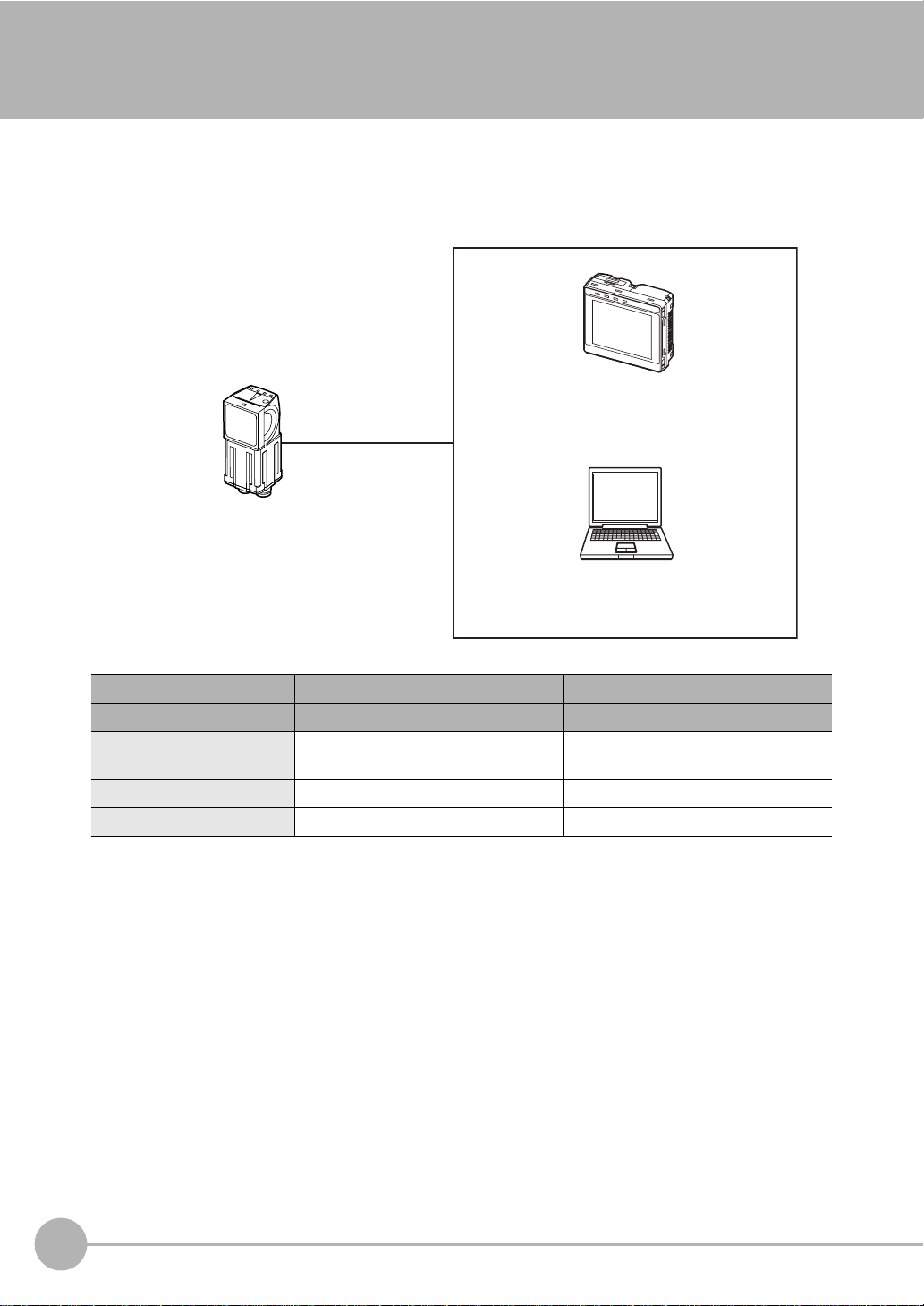
1-1 FQ-series Vision Sensors
FQ-series Vision Sensors are real-color Vision Sensors with integrated processing. Once configured, they are
used stand-alone for quality inspection of presence, position, and other product characteristics. To set up or
monitor the sensors, either the touch screen based console 'Touch Finder' or a 'PC Tool' can be used.
Setup, Image Confirmation, and Logging Tools
Touch Finder
FQ Vision Sensor
Used to check images and set the judgement
parameters. It can also be used to save
measurement results and check status during
operation.
PC Tool
Includes the camera, lighting, measurement
processor, and I/O functions.
After the Sensor has been set up, it can be
operated alone to perform measurements
without the Touch Finder or PC Tool.
The same functions as those that are provided
by the Touch Finder can be performed from a
computer. The PC Tool is available free of
charge.
FQ-series Vision Sensors are available in two different models. The differences are given in the following table.
Model Standard model Single-function model
Model number FQ-S2@@@@@ FQ-S1@@@@@
Number of simultaneous
measurements
Number of registered scenes 32 8
Position compensation Supported Not supported
32 1
14
FQ-series Vision Sensors
FQ User’s Manual
Page 19
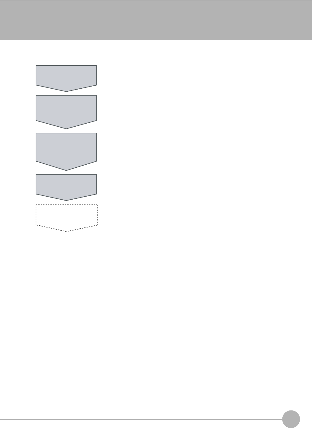
1-2 Measurement Process
This section describes the basic flow of the measurement process.
Trigger input
Take image
Measurement
Overall judgement
output
Logging
• The measurement is started by inputting a trigger signal from an external
device.
• Images are taken according to the trigger.
• The image is measured to see if it matches the configured settings.
• The overall judgement of all inspection items are output using OR logic.
• Measurement data and image data can be logged in memory in the Sensor or
in an SD card.
1
Introduction
FQ User’s Manual
Measurement Process
15
Page 20
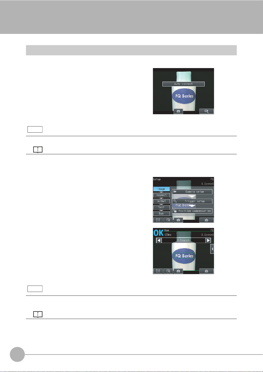
1-3 Startup Display and Display Elements
Startup Display
1 The Sensor is automatically detected by the Touch
Finder when power supply to the Sensor and Touch
Finder is turned ON.
The Auto Connect Display will appear if the Sensor cannot be detected. Check that cables are connected correctly to the Sensor and Touch Finder, and then press
[Auto connect].
Note
If the Sensor is still not detected after pressing [Auto Connect], refer to the following information.
The Sensor cannot be detected: p. 134
2 When the Sensor is detected, the following display will appear.
• The Setup Mode will appear if a Sensor that has not been
set up is connected.
• The Run Mode will appear if a Sensor that has been set
up is connected.
Note
When the Touch Finder is started, IP addresses are automatically set for each Sensor.
To allocate specific IP addresses, set the IP address of each Sensor and the Touch Finder.
Setting Up Ethernet: p. 33
16
Startup Display and Display Elements
FQ User’s Manual
Page 21
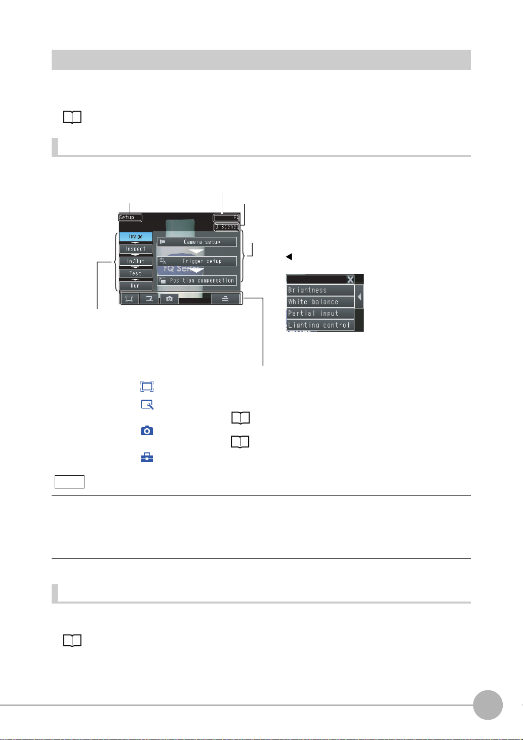
Display Elements
This Sensor has a Setup Mode and a Run Mode.
Refer to the following information for menu items.
p. 114
Setup Mode
In Setup Mode, you can set the image conditions, judgement parameters, and I/O settings for the Sensor.
The name of the mode or the
menu hierarchy is displayed.
The setup flow is shown by these five tabs.
[Image]: Used to adjust the image.
[Inspect]: Used to set the inspection items.
[In/Out]: Used to set the I/O.
[Test]: Used to test and adjust the set measurements.
[Run]: Used to switch to Run Mode.
Only-image Button: Used to select either displaying the camera image and messages, or
Display Button: Used to select the source of the image or to zoom the image.
Capture Button: Used to capture the current screen to the SD card.
Tool Button: Used to call functions, such as saving data or select scenes.
The name of the Sensor being set up is displayed.
The selected scene number is displayed.
The menu changes according to the selected tab page.
• Buttons will appear on the right according to the mode.
• If the [ ] Button appears, pressing it will display the
sub-menu or commands.
This button menu is always displayed.
only the camera image.
Display Functions: p. 94
p. 10 9
1
Introduction
Note
The Display Button can be used to switch between the following images.
• Live: The live image is displayed.
• Freeze: The image that was taken last is displayed.
• Log: An image saved in internal memory is displayed.
• File: An image saved on an SD card is displayed.
Run Mode
In Run Mode, measurements are performed, and measurement results are output.
p. 81
FQ User’s Manual
Startup Display and Display Elements
17
Page 22
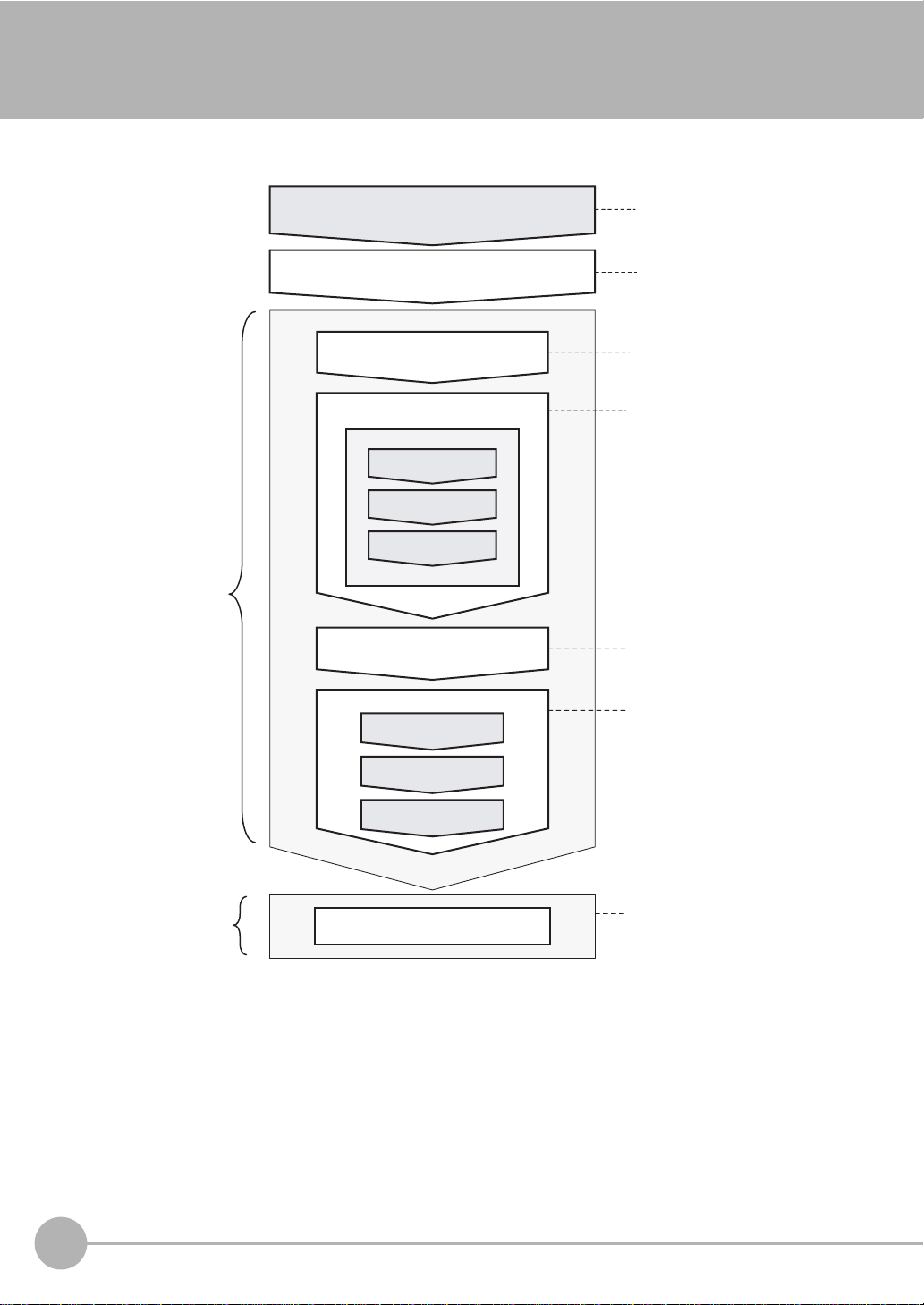
1-4 Basic Operational Flow
The following flow shows the basic operation of FQ-series Vision Sensors.
Setup Evaluation
Connections and Wiring
Starting the Sensor
Section 2 Installation
and Connections
Section 1
1-3 Startup Display
and Display Elements
Image Setup
([Image] Tab Page)
Inspection Setup
([Inspect] Tab Page)
Registering
Inspection Items
Teaching
Setting Judgement
Parameters
*1
Output Settings
([In/Out] Tab Page)
Section 3 Taking
Images
Section 4 Setting Up
Inspections
Section 8
Communications with
External Devices
Testing ([Test] Tab Page)
Test Measurement and
Results Verification
Adjusting Judgement
Parameters
Section 5 Testing and
Saving Settings
Saving the Settings
Operation
*2
Starting Operation (Run Mode)
Section 6 Operation
*1: In Setup Mode, the Sensor can be set up and adjusted, but it does not output signals on the I/O lines.
*2: In Run Mode, the Sensor performs measurements and outputs signals on the I/O lines.
18
Basic Operational Flow
FQ User’s Manual
Page 23

Installation and Connections
2-1 System Configuration . . . . . . . . . . . . . . . . . . . . . . . . . . . . . . . . . . . . . . 20
2-2 Part Names and Functions . . . . . . . . . . . . . . . . . . . . . . . . . . . . . . . . . . 21
FQ Vision Sensor. . . . . . . . . . . . . . . . . . . . . . . . . . . . . . . . . . . . . . . . . . . . . . . . . . 21
Touch Finder . . . . . . . . . . . . . . . . . . . . . . . . . . . . . . . . . . . . . . . . . . . . . . . . . . . . . 22
2-3 Installation . . . . . . . . . . . . . . . . . . . . . . . . . . . . . . . . . . . . . . . . . . . . . . . 23
Installing the Sensor . . . . . . . . . . . . . . . . . . . . . . . . . . . . . . . . . . . . . . . . . . . . . . . 23
Installing the Touch Finder. . . . . . . . . . . . . . . . . . . . . . . . . . . . . . . . . . . . . . . . . . . 24
2-4 Wiring . . . . . . . . . . . . . . . . . . . . . . . . . . . . . . . . . . . . . . . . . . . . . . . . . . .28
Wiring. . . . . . . . . . . . . . . . . . . . . . . . . . . . . . . . . . . . . . . . . . . . . . . . . . . . . . . . . . . 28
Wiring the Touch Finder . . . . . . . . . . . . . . . . . . . . . . . . . . . . . . . . . . . . . . . . . . . . . 30
2-5 Setting Up Ethernet . . . . . . . . . . . . . . . . . . . . . . . . . . . . . . . . . . . . . . . . 33
2
Installation and Connections
Page 24
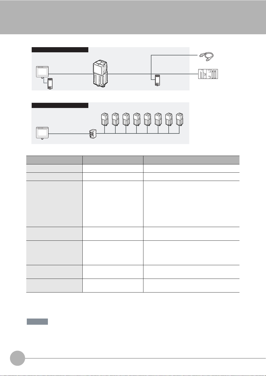
2-1 System Configuration
Standard Configuration
Setup Tool
Touch Finder or PC Tool
FQ Ethernet Cable I/O Cable
24-VDC power supply
Multiple Connection Sensors
Setup Tool
Touch Finder or PC Tool
Switching Hub
Standard RJ45 Ethernet
Cable
FQ Vision Sensor
FQ Vision Sensors
(8 max.)
FQ Ethernet Cable
24-VDC power
supply
Trigger Sensor
PLC
Connect the trigger
sensor, PLC, and
power supply to
each Sensor.
Product Model number Remarks
FQ Vision Sensor FQ-S@@@@@@ This is the Vision Sensor.
Touch Finder FQ-D@@ This is a setup console.
PC Tool --- The PC Tool can be used instead of the Touch
Finder. If you register as a member, you can download the free PC Tool as a special service to purchasers.
Refer to the Member Registration Sheet that is
enclosed with the Sensor for the member registration procedure and the download procedure for special member software.
FQ Ethernet Cable FQ-WN0@@ Connects the Sensor to the Touch Finder or com-
puter.
Standard RJ45 Ethernet
*1
Cable
--- Connects the switching hub to the Touch Finder or
computer. Use a connector that complies with the
FCC RJ45 standard. (STP (shielded twisted-pair)
cable, category 5e or 6, impedance: 100 Ω)
I/O Cable FQ-WD0@@ Connects the Sensor to the power supply and exter-
nal devices.
Switching Hub W4S1-0@@ Used to connect multiple Sensors to one Touch
Finder or PC Tool.
*1: The shape and dimensions of the Ethernet connector plug and jack are specified in ISO/IEC8877:1992 (JIS X 5110:1996) and RJ-45 of the
FCC regulations.
To prevent connector connection failures, the structure of the jack of this product does not allow insertion of plugs that do not comply with the
standard.
If a commercially available plug cannot be inserted, it is likely that the plug is non-compliant.
Important
Do not connect network devices other than PLCs on the same network as the Touch Finder or computer. If
another device is connected, the responsiveness of displays and settings of the Touch Finder or computer may
become slow.
20
System Configuration
FQ User’s Manual
Page 25
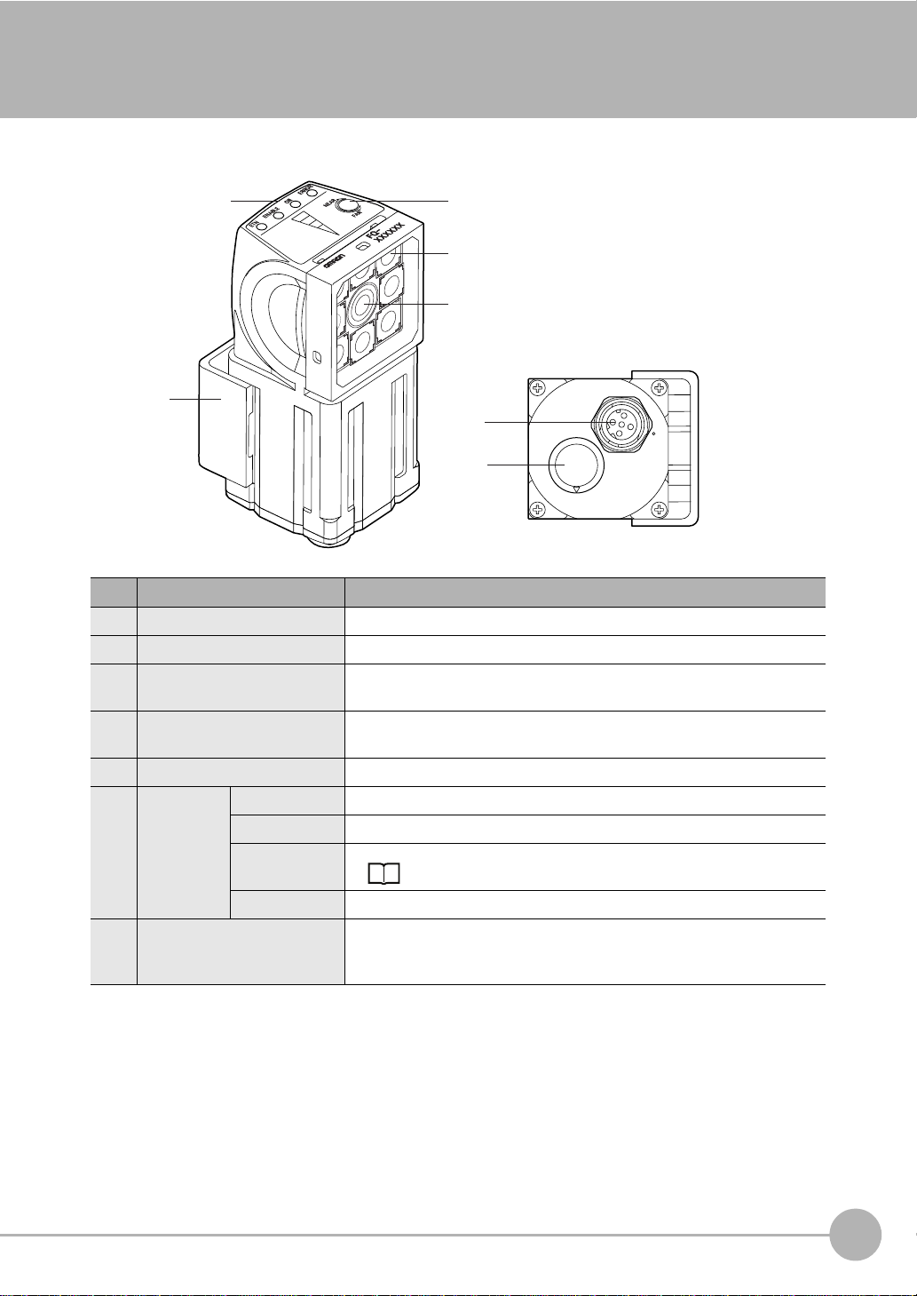
2-2 Part Names and Functions
FQ Vision Sensor
(6)
(7)
No. Name Description
(1) Lighting LEDs for illumination
(2) Camera lens This lens can be focused.
(3) I/O Cable connector An I/O Cable is used to connect the Sensor to the power supply and exter-
nal I/O.
(4) Ethernet cable connector An Ethernet cable is used to connect the Sensor to the Touch Finder or a
computer.
(5) Focus adjustment screw Used to adjust the focus of the image.
(6) Operation
indicators
(7) Mounting Bracket Used to mount the Sensor.
OR Lights orange when the OR output signal turns ON.
ETN Lights orange during Ethernet communications.
ERROR Lights red when an error occurs.
9-1 Error Table p. 132.
BUSY Lights green when the Sensor is executing a process.
The Mounting Bracket can be attached to the front, left side, right side, or
back of the Sensor.
(5)
(1)
(2)
(4)
(3)
2
Installation and Connections
FQ User’s Manual
Part Names and Functions
21
Page 26
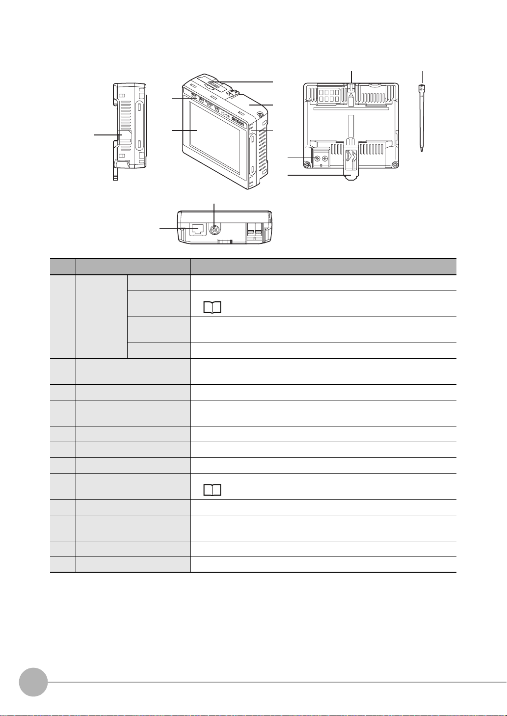
Touch Finder
(1)
(6) (7)
(3)
(4)
(5)
(2)
(12)
(10)
(11)
(8)
(9)
No. Name Description
(1) Operation
indicators
(2) LCD/touch panel Displays the setting menu, measurement results, and images input by the
(3) SD card slot An SD card can be inserted.
(4) Battery cover
(5) Power supply switch Used to turn the Touch Finder ON and OFF.
(6) Touch pen holder The touch pen can be stored here when it is not being used.
(7) Touch pen Used to operate the touch panel.
(8) DC power supply connector Used to connect a DC power supply.
(9) Slider Used to mount the Touch Finder to a DIN Track.
(10) Ethernet port Used when connecting the Touch Finder to the Sensor with an Ethernet
(11) Strap holder This is a holder for attaching the strap.
(12) AC power supply connector*1Used to connect the AC adapter.
*1: Applicable to the FQ-D31 only.
POWER Lights green when the Touch Finder is turned ON.
ERROR Lights red when an error occurs.
9-1 Error Table p. 132.
SD ACCESS Lights yellow when an SD card is inserted.
Flashes yellow when the SD card is being accessed.
CHARGE
*1
*1
Lights orange when the Battery is charging.
camera.
The Battery is inserted behind this cover.
Remove the cover when mounting or removing the Battery.
p. 30
cable. Insert the connector until it locks in place.
22
Part Names and Functions
FQ User’s Manual
Page 27
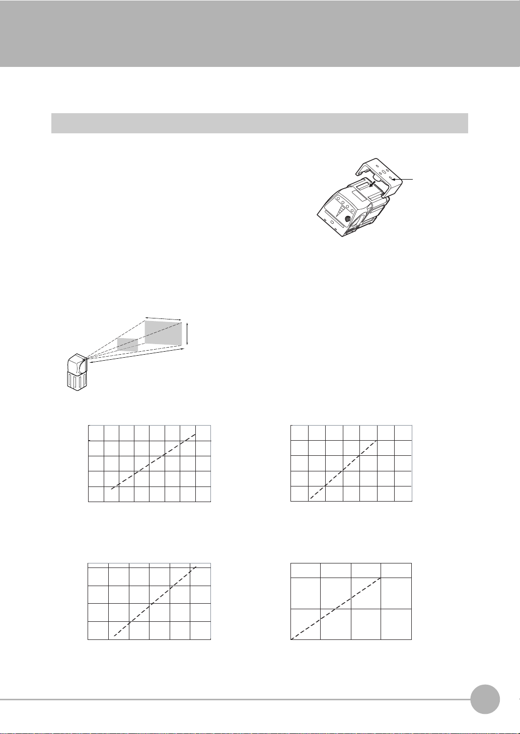
2-3 Installation
Installing the Sensor
Installation Procedure
1 Align the tabs on one side of the Mounting Bracket with
the slot on the Sensor.
The FQ-XL Mounting Bracket can be attached to the back,
side, or front of the Sensor.
2 Press the Mounting Bracket onto the Sensor until the oth-
er tabs click into place.
3 Use the following optical charts to check the field of view
and installation distance of the Sensor so that it is mounted at the correct position.
Tightening torque (M4): 1.2 N·m
Horizontal field of view
Vertical field
of view
Installation distance (L)
The optical chart indicates the horizontal
field of view. The vertical field of view will
be approximately 60% of the horizontal
field of view.
Note: The tolerance is ±10%.
Mounting
Bracket
2
Installation and Connections
FQ-S10010F, FQ-15010F,
FQ-S20010F, or FQ-25010F
Installation distance (L) (mm)
55
45
35
6
FQ-S10050F, FQ-S15050F,
FQ-S20050F, or FQ-S25050F
Installation distance (L) (mm)
210
130
50
0 20 40 60
8 10 12 14
Horizontal field of view (mm)
Horizontal field of view (mm)
FQ-S10100F, FQ-S15100F,
FQ-S20100F, or FQ-S25100F
Installation distance (L) (mm)
1,000
600
200
0100200 300
Horizontal field of view (mm)
FQ-S10100N, FQ-S15100N,
FQ-S20100N, or FQ-S25100N
Installation distance (L) (mm)
400
0
0
200 400
Horizontal field of view (mm)
FQ User’s Manual
Installation
23
Page 28
Important
• There is a certain amount of deviation among Sensors in the center of the optical axis. For this reason, when install-
ing the Sensor, check the center of the image and the field of view on the LCD monitor of the Touch Finder and in
the PC Tool.
Removal Procedure
1 Insert a flat-blade screwdriver between the Mounting Brack-
et and the Sensor case on either side and remove the
Mounting Bracket.
Mounting
Bracket
Installing the Touch Finder
Installation Precautions
Install the Touch Finder in the following orientation to allow sufficient heat dissipation.
Do not mount it in the following orientations.
Important
• To improve ventilation, leave space on both sides of the Touch Finder. The distance between the Touch Finder and
other devices should be at least that shown in the following diagram.
15 mm min.
• Make sure that the ambient temperature is 50°C or lower. If it exceeds 50°C, install an cooling fan or an air condi-
tioner and maintain the temperature at 50°C or lower.
• To prevent interference by noise, do not mount the Sensor on panels which contain high-voltage devices.
• To keep the level of noise from the surrounding environment to a minimum, install the Sensor and Touch Finder at
least 10 m away from power lines.
24
Installation
15 mm min.
FQ User’s Manual
Page 29
Mounting to DIN Track
Installation Procedure
1 Press the slider on the Touch Finder to the top.
2 Hook the clip at the top of the Touch Finder on to the DIN
Track.
3 Press the Touch Finder onto the DIN Track until the bottom
clip clicks into place.
3
Important
• Attach End Plates (sold separately) on the sides of the Touch Finder on the DIN Track.
• If other devices will be installed next to the Touch Finder on the same DIN Track, make sure that sufficient space is
kept between the devices as indicated on previous page.
• Always hook the clip at the top of the Touch Finder on the DIN Track first. If the lower clip is hooked on first, the
Touch Finder will not be mounted very securely.
Removal Procedure
2
3
1
1 Pull down on the slider on the Touch Finder.
2 Lift the Touch Finder at the bottom and remove it from the
DIN Track.
2
1
2
Installation and Connections
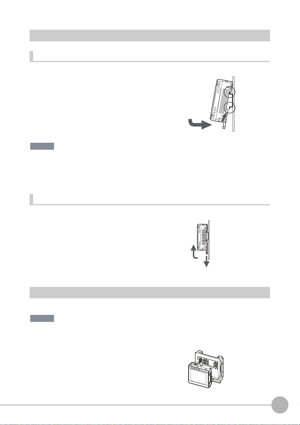
Mounting to a Control Panel
The Touch Finder can be mounted on a panel using the FQ-XPM Panel Mounting Adapter.
Important
• Always turn OFF the Touch Finder power before attaching or detaching the Panel Mount Adapter. Attaching or
detaching with the power turned ON may cause a failure.
1 Set the Touch Finder in the Panel Mount Adapter.
FQ User’s Manual
Installation
25
Page 30
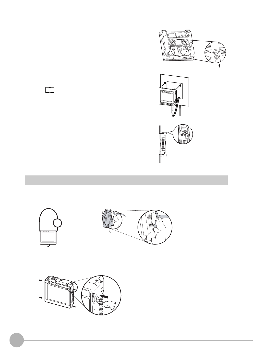
2 Press the slider up on the Touch Finder.
3 Create holes in the panel for mounting.
Refer to the following page for hole dimensions.
p. 152
4 Connect the cable to the Touch Finder.
5 Mount the Touch Finder with the Panel Mount Adapter from
the front of the panel.
6 Hook the hooks on the Mounting Bracket in the four holes
of the Panel Mount Adapter and secure them with screws.
(Tightening torque: 1.2 N·m)
7 Check that the Touch Finder is attached properly to the
Panel.
Mounting
Bracket
Using the Touch Finder as a Portable Device (with Battery)
The Touch Finder with a Battery can be used as a portable device. Use the strap when carrying it to prevent
dropping it.
There are two types of straps (FQ-XH, sold separately), a Neck Strap and a Hand Strap.
Neck Strap
Hand Strap
1 Attach the Mini-strap to the Touch Finder.
There are a total of four holes for attaching the Mini-strap on the left and on the right of the Touch Finder.
26
Installation
FQ User’s Manual
Page 31

2 Connect the Neck Strap or Hand Strap to the Mini-strap.
Mini-strap
Neck Strap or Hand
Strap
2
Installation and Connections
FQ User’s Manual
Installation
27
Page 32

2-4 Wiring
Wiring the Sensor
Connect the I/O Cable to the I/O Cable connector located at the bottom of the Sensor.
Important
FQ-WD0@@
I/O Cable
Brown
Blue
Black
Orange
Light blue
Pink
Gray
Green
Red
White
Purple
Yellow
Power supply
GND
OUT0 (OR)
OUT1 (BUSY)
OUT2 (ERROR)
TRIG
IN0
IN1
IN2
IN3
IN4
IN5
Cut off lines that are not required so that they do not come into contact the other signal lines.
Classification
Powe r
supply
Inputs TRIG This terminal is the trigger signal input.
Outputs OUT0 (OR) By default, this is the OR output signal (overall judgement).
Signal Application
Power supply
(24 V)
GND
IN0 to IN5 These are the command input terminals.
OUT1 (BUSY) By default, this is the BUSY output signal.
OUT2 (ERROR) By default, this is the ERROR output signal.
These terminals are for the external power supply (24 V).
Important
Wire the power supply separately from other devices. If the wiring for other devices is placed
together or in the same duct as the wiring for the Vision Sensor, the influences of electromagnetic
induction may cause the Sensor to malfunction or may damage it.
The assignment can be changed to an individual judgement signal from OR0 to OR31.
The assignment can be changed to an individual judgement signal from OR0 to OR31.
The assignment can be changed to an individual judgement signal from OR0 to OR31.
Note
The assignments of I/O signals can be changed.
Section 8 Communications with External Devices: p. 113
28
Wiring
FQ User’s Manual
Page 33

I/O Signal Circuit Diagrams
PNPNPN
Internal circuits
Power supply (24 VDC)
Brown
Pink
TRIG
IN0
Gray
GreenOrange
IN1
Red
IN2
IN3
White
Purple
IN4
IN5
Light blue
Orange
Black
Blue
OUT2 (ERROR)
OUT1 (BUSY)
OUT0 (OR)
GND (0V)
24 VDC
Load
Internal circuits
Power supply (24 VDC)
Brown
Black
OUT0 (OR)
OUT1 (BUSY)
Light blue
Blue Yellow
GND (0V)
Pink
TRIG
IN0
Gray
IN1
Green
IN2
Red
IN3
White
Purple
IN4
IN5
Yellow
Load
OUT2 (ERROR)
24 VDC
Important
Preventing Chattering
• The Sensor is equipped with an anti-chattering function, but if the chattering is 100 µs or longer, a faulty input may
occur. (Input signals of 99 µs or shorter are ignored. Signals of 100 µs or longer are treated as input signals.)
• Use no-contact output devices (e.g., SSR or PLC transistor output) for the input signals. If contacts (e.g., relay) are
used, chattering may cause the trigger to be input again during execution of a measurement.
Power Supply Specifications When a Switching Regulator Is Connected
Use a power supply that meets the following specifications. (The power supply is sold separately.)
Item Description
Power supply voltage 24 VDC (21.6 to 26.4 V)
Output current 3.75 A min.
Recommended Power Supply S8VS-09024@ (24 VDC, 3.75 A)
External power supply terminal screws M4 (tightening torque: 1.2 N·m)
2
Installation and Connections
Important
Supply power from a DC power supply for which measures have been applied to prevent high voltages (e.g., a safety
extra low voltage circuit).
If UL certification is required for the overall system, use a UL Class II DC power supply.
Attaching the LED Warning Label
Attach the enclosed LED warning label to the cable or other location. The LED warning label must be attached
to a location that is readily visible from the Sensor.
Attachment Example
Warning Label
10-4 LED Safety p. 157
FQ User’s Manual
Warning Label
Max.60mW 400msec
400-700nm
JIS C 6802:2005
LED RADIATION
DO NOT STARE
INTO BEAM
Max.60mW 400msec
400-700nm
CLASS 2 LED PRODUCT
IEC 60825-1:1993 +A1:1997
+A2:2001
Wiring
29
Page 34

Wiring the Touch Finder
Power Supply Wiring
Connecting the Power Supply
1 Loosen the two terminal screws using a Phillips
screwdriver.
2 Attach crimp terminals to the power lines.
Secure the positive and negative lines as indicated
using M3 screws.
Power supply tightening torque: 0.54 N⋅m
3 In environments where there is excessive noise, at-
tach a ferrite core (ZCAT1730-0730 from TDK or the
equivalent) to the power supply cable.
Turning ON the Touch Finder
24 VDC
When you attach the ferrite core to
the power supply cable, wrap the
cable only one time.
+
−
1 Remove the cover from the power switch on the left side of
the Touch Finder.
2 Press the switch toward ON.
1
Power Supply Specifications
Use a power supply that meets the following specifications. (The power supply is sold separately.)
Item Description
Power supply voltage 24 VDC (21.6 to 26.4 V)
Output current 2.5 A min.
Recommended Power Supply S8VS-06024@ (24 VDC, 2.5 A)
External power supply terminal screws M4 (tightening torque: 1.2 N⋅m)
Recommended power line wire size AWG16 to AWG22 (length of 5 m max.)
Important
• Supply power from a DC power supply for which measures have been applied to prevent high voltages (e.g., a
safety extra low voltage circuit).
If UL certification is required for the overall system, use a UL Class II DC power supply.
• When using the FQ-D31, do not connect a switching regulator and AC Adapter (FQ-AC@) at the same time.
2
ON
OFF
30
Wiring
FQ User’s Manual
Page 35

Charging the Battery
This section describes how to charge and install the FQ-D31 Battery and provides applicable precautions.
Charge the Battery while it is attached to the Touch Finder.
Use the AC adapter to charge the battery.
Mounting the Battery in the Touch Finder
1 Remove the screw from the battery cover on the top of the
Touch Finder, slide the cover in the direction of the arrow,
and open the battery cover.
2 Face the rounded side of the battery toward the back of the
Touch Finder and insert the battery.
Important
Do not insert the battery in the wrong orientation.
3 Close the battery cover, slide the battery cover in the direc-
tion of the arrow, and tighten the screw on the battery cover.
2
Installation and Connections
4 Attach the AC adapter to the Touch Finder to start changing
the battery.
The CHARGE indicator will be lit while the battery is being
charged. It will go out when charging the battery has been completed.
Note
The Touch Finder will operate even if the AC adapter is connected when no battery is mounted in the Touch Finder.
FQ User’s Manual
CHARGE indicator
Wiring
31
Page 36

Important
• If the Touch Finder (FQ-D31) will be installed permanently or semi-permanently, remove the Battery (FQ-BAT1). If
the rated temperature is exceeded with the Battery inserted, the protective circuit may activate and stop the Touch
Finder.
• The battery complies with the following recycling regulation.
Japan Taiwan
EU
Li-ion00
• California regulations concerning perchlorate:
This product is a lithium battery that contains perchlorate, which is regulated by the State of California. Please com-
ply with these regulations. For details see the following URL:
www.dtsc.ca.gov/hazardouswaste/perchlorate/
32
Wiring
FQ User’s Manual
Page 37

2-5 Setting Up Ethernet
Connecting to Sensors from the Touch Finder
When the Sensor is used with a Touch Finder, IP addresses are automatically assigned. No settings are
required to use Ethernet.
However, if a Sensor or Touch Finder is connected to a network where a PLC or computer is already
connected, the Ethernet must be set to be compatible with the existing network.
• Touch Finder
(Setup Mode) − [TF settings] − [Ethernet]
1 Set the IP address and subnet mask according to the network settings.
Connecting to Sensors from a Computer Using the PC Tool
When connecting the Sensor directly to a computer using an Ethernet Cable, set the network settings on the
computer as given below. Setting a fixed IP address is not required if there is a hub between the computer and
Sensor and a DHCP server is used.
The following procedure is for Windows XP.
1 Select [Control Panel] from the Windows Start Menu.
2
Installation and Connections
2 Click [Network and Internet Connections] in the control
panel and then double-click [Network Connections].
3 Right-click the [Local Area Connection] Icon and select
[Properties].
FQ User’s Manual
Setting Up Ethernet
33
Page 38

4 On the [General] Tab Page, double-click Internet Proto-
col (TCP/IC).
5 Select the Use the following IP address Option and en-
ter the following IP address and subnet mask.
• IP address: 10.5.5.101
• Subnet mask: 255.255.255.0
6 Click the [OK] Button. This completes the settings.
34
Setting Up Ethernet
FQ User’s Manual
Page 39

Taking Images
3-1 Selecting a Sensor for Configuration. . . . . . . . . . . . . . . . . . . . . . . . . . 36
3-2 Adjusting Image Quality . . . . . . . . . . . . . . . . . . . . . . . . . . . . . . . . . . . . 37
3-3 Adjusting the Object Position . . . . . . . . . . . . . . . . . . . . . . . . . . . . . . . . 42
3-4 Preventing Mutual Interference of Multiple Sensors . . . . . . . . . . . . . 46
3
Taking Images
Page 40

3-1 Selecting a Sensor for Configuration
If multiple Sensors are connected to a single Touch Finder or computer, you can select the Sensor that you
want to set up.
1 Press [Run].
This will enable setting the current Sensor into RUN
Mode before selecting another Sensor.
2 Then press [Switch to Run mode].
3 Press [Yes].
4 Press − [Switch Sensor].
5 Press the image of the Sensor to be set up.
will be displayed for Sensors that are not yet set.
Note
Once the Touch Finder detects and records a Sensor, the display order for showing more than one Sensor is fixed. Even if the system
configuration is changed to reduce the number of Sensors, the previous display location will remain for Sensors that were removed.
To update displays of multiple Sensors to the current connection sta-
tus, press [ ] - [Auto connect] on the right of the display in step 5,
above, to automatically reconnect.
6 Press − [Sensor settings] to return to Setup
Mode.
7 Press [Yes].
36
Selecting a Sensor for Configuration
FQ User’s Manual
Page 41

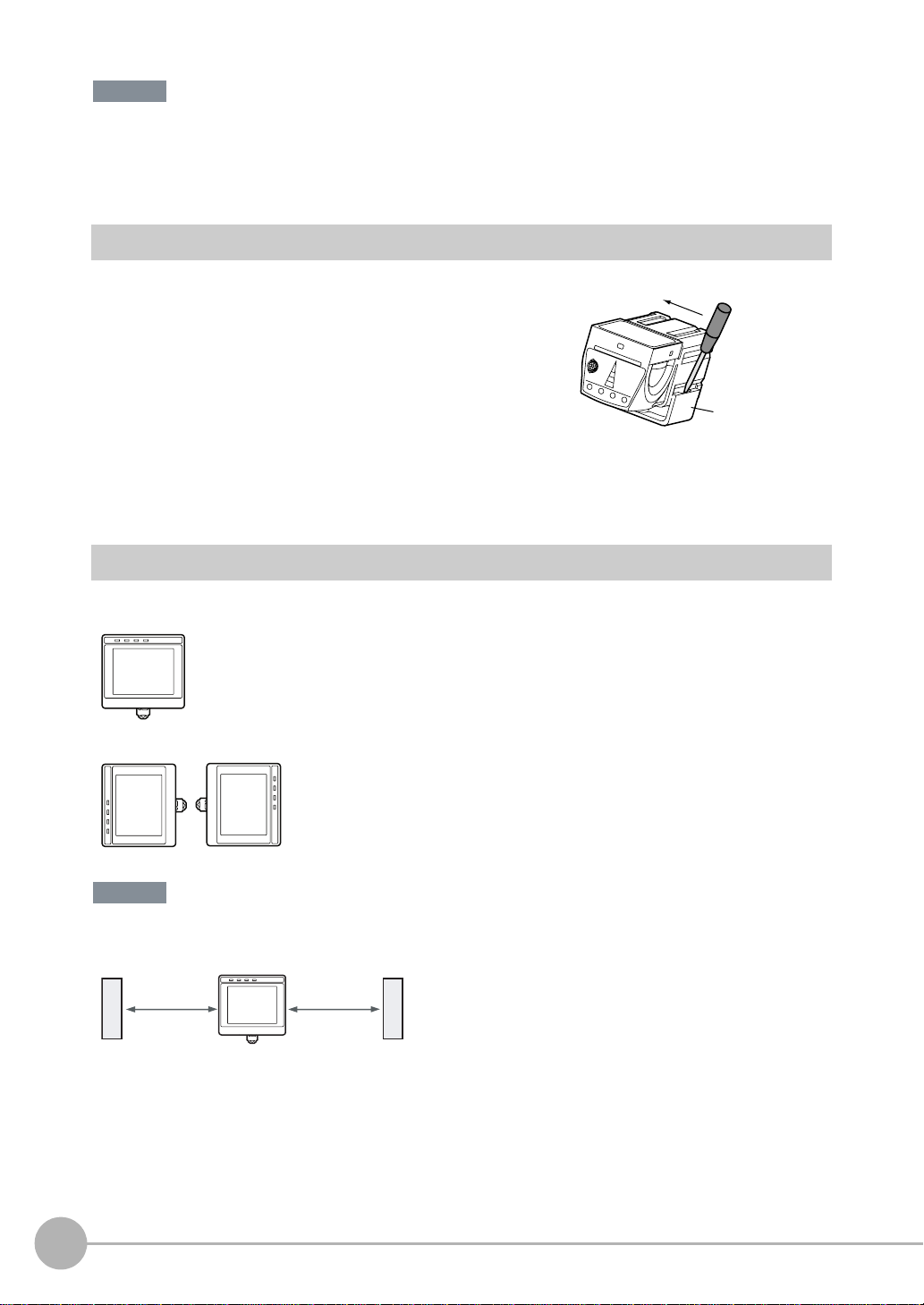
3-2 Adjusting Image Quality
Adjusting the Focus
[Image] − [Camera setup]
1 Display the Camera Setup Display.
The focus can be seen as a numerical value. The higher
the value, the better the focus.
Focus Level
2 Manually adjust the focus using the focus adjust-
ment screw on the Sensor while checking the image
and focus value on the Touch Finder.
In the default settings, the field of view is set to the narrowest setting.
3 Press [Back].
Focus adjustment screw
Turn clockwise to focus on closer objects.
3
Taking Images
(The field of view will
narrow.)
Turn the screw counterclockwise
to focus on objects at a distance.
(The field of view will widen.)
Important
• Turn the focus adjustment screw clockwise or counterclockwise a little bit to make sure that it has not already
reached the dead stop. Do not force the screw if it does not rotate anymore. This will damage the Sensor.
• Do not turn the focus adjustment knob with a force that is greater than 0.1 N·m. This may damage it.
FQ User’s Manual
Adjusting Image Quality
37
Page 42

Adjusting the Brightness
To achieve stable measurements, the brightness of the camera image must be adjusted so that the
characteristic to be measured is clearly visible.
Dark
Brightness of image
Bright
0
100
[Image] − [Camera setup]
1 Press [ ] - [Brightness] on the right side of the dis-
play.
2 Move the bar to the left or right to adjust the bright-
ness.
Moving it to the right will make the image brighter, while
moving it to the left will reduce the brightness of the image.
Press [AUTO] to automatically adjust the brightness according to the image.
3 Press [OK].
Important
The exposure time will be longer for larger values. This may cause the image to blur if the object is moving fast.
If the Sensor is used on a high-speed line, check that the images are not blurred under actual operating
conditions.
Taking Clear Images of Moving Objects
For quick moving objects, the effect of blurring can be reduced by decreasing the exposure time.
Fast
1/30,000 1/250
Moving speed
Exposure time
Slow
1000
[Image] – [Camera setup] – [ ] – [Brightness]
Adjusting the Brightness: p. 38
Important
The image becomes darker the smaller the exposure time. If the Sensor is used in a dark environment, make
sure that the darkness of the image does not cause the measurements to be unstable.
38
Adjusting Image Quality
FQ User’s Manual
Page 43

Improving the Image Quality of Metallic and other Shiny Surfaces
When objects with shiny surfaces are being measured, the lighting may be reflected off the surface and affect
the image.
To remove reflections, one of the following two functions can be used.
Function Description
HDR (High Dynamic Range) If objects have contrasting light and dark areas, the dynamic range can be made wider to
Polarizing filter Specular reflections can be eliminated from an image by attaching a polarizing filter to the
• Selection Tips
• When the measurement object is not moving → Use the HDR function.
• When the measurement object is moving → Use a polarizing filter.
improve the quality of the images.
Sensor.
3
HDR Function
The HDR function is used for objects that have a large difference between light and dark areas. For this kind of
object, clear images cannot be achieved with the standard brightness setting. The HDR function combines
several images of different brightnesses (exposure times) so that the resulting image has a lower degree of
contrast and can be measured stably for the desired characteristic.
Inputting Images with a Limit Range of Brightness
Combining Images to Create an Image
with a Wide Dynamic Range
Dark
Bright
Taking Images
FQ User’s Manual
Adjusting Image Quality
39
Page 44

Observe the following precautions.
• Use the HDR function only for objects that are not moving to avoid image blurring.
Several images are taken with different shutter speeds and combined. If the object moves while the image
is being taken, the image will become blurred.
• Images with different brightnesses are combined, so the resulting image will have a lower degree of contrast.
[Image] − [Camera setup]
1 Press [ ] − [Brightness] on the right side of the display.
2 Press the [HDR ON] Button.
The best HDR mode will be selected automatically.
The enabled range will appear in blue on the brightness adjustment bar.
3 Press the [OK] Button.
Note
• If the measurement object is changed after setting the HDR function, press
the [AUTO] Button to automatically set the HDR mode again.
• If the automatic selection does not achieve the desired results, press the
[HDR] Button and manually set the best HDR mode. As shown below, the
higher the level, the wider the combined dynamic range will be.
Level 1
Level 2
Level 3
Level 4
Dark
• If the reflections cannot be sufficiently removed using the HDR function,
use a polarizing filter as well.
Bright
Using a Polarizing Filter
Specular reflections can be eliminated from an image by attaching a FQ-XF1 Polarizing Filter to the Sensor.
Observe the following precautions.
• The image will be darker compared to when no filter is used.
• If the image becomes too dark, adjust the brightness.
p. 38
• Mounting the Filter
1 Hook the filter in the hole at the top of the Sensor.
40
Adjusting Image Quality
FQ User’s Manual
Page 45

2 Using the top section as a pivot point, pull down the
filter so that it attaches to the Sensor.
Adjusting the Colors of the Image (White Balance)
If external lighting is used, the image may appear as having different colors than the actual object. If this is the
case, adjust the white balance.
If the lighting built in to the Sensor is used, the white balance is already adjusted. No setting is required in this
case.
[Image] − [Camera setup]
1 Input a picture of white paper or cloth.
2 Press [ ] – [White balance] on the right side of the
display.
3 Press the [Auto] Button. The Sensor will automatical-
ly adjust the colors.
4 Move the bar to the left (light) or right (dark) to fine-
tune the colors.
5 Press [OK].
3
Taking Images
FQ User’s Manual
Adjusting Image Quality
41
Page 46

3-3 Adjusting the Object Position
If objects are moving, the position in the image of the characteristic that is to be measured will vary according
to the timing of the trigger signal. The FQ Vision Sensor offers two different ways to adjust this position
variation.
Function Description Reference
Position compensation If the timing of the trigger is accurate, the FQ Vision Sensor can correct variations in the
Trigger delay A delay can be applied from when the trigger (the TRIG signal) is input until when the
position of the object for each measurement with the Position Compensation function.
image is input, to synchronize the timing of image input with the speed of the moving
objects.
Position Compensation
The FQ Vision Sensor performs measurements in measurement regions that are set to a fixed shape and
position by the operator. A measurement is not performed properly if the object is not positioned inside this
measurement region (e.g., the result will be NG even if the object is OK). In machines in which the position of
the object varies for each image, stable measurements would be impossible. To cope this problem, the Position
Compensation function aligns the whole image so that the object to be measured is moved exactly to the
measurement region.
Reference position (as set by the operator)
The measurement object is properly within the measurement region.
Measurement region
p. 42
p. 45
Object
Object is out of place:
The measurement object is
outside the measurement
region.
Position compensation applied...
The image is aligned so that the object
is returned to the reference position
before performing measurements.
[Image] – [Position compensation] – [Mode on/off]
1 Press [ON] for [Mode on/off]
2 Press [Settings].
The object is measured
properly within the
measurement region.
42
Adjusting the Object Position
FQ User’s Manual
Page 47

3 Press [Teach].
4 Adjust the image so that the measurement object is
in the center.
5 Press [ ] – [Model region].
6 Move the rectangle so that the characteristic part for
position compensation is inside it.
7 Press [OK].
8 Press [Teach].
The characteristic part and reference position for position
compensation will be registered.
9 Press [OK] to save the settings.
Drag the rectangle to move it.
Drag a corner to size the rectangle.
3
Taking Images
FQ User’s Manual
Adjusting the Object Position
43
Page 48

Adjusting the Judgement Parameters
Set how similar the image must be to the registered image for position compensation to be applied.
[Image] – [Position compensation] – [Settings] – [Judgement]
1 Set the correlation range for an OK judgement.
Operating procedures: p. 52
Measures to Stabilize Position Correction
• Low Mark Contrast and Inconsistent Correlations
Areas with high contrast are registered as model registration sections.
The adjustment procedure is the same as for the search function.
Or, adjust the brightness to increase the contrast of the mark.
Making dark images brighter: p. 38
• Inconsistent Marks and Inconsistent Correlations
Inconsistent portions can be masked so that are omitted from matching.
Operating procedures for other functions are basically the same as those for searching.
Refer to the following information.
Unstable search results: p. 54
Increasing the Speed of Position Compensation
The following method can be used to reduce processing time.
• Reduce the range in which searches are performed for the model.
Operating procedures for other functions are basically the same as those for searching.
Refer to the following information.
Changing the measurement region: p. 57
44
Adjusting the Object Position
FQ User’s Manual
Page 49

Adjusting the Image Timing
The internal timing for taking an image can be set to be delayed in relation to the external trigger signal. This
can be used to adjust the object position in the image, e.g., if an external trigger sensor is used. If the object
position still varies in the image the Position Compensation function must also be used.
Delay time
Delay from when the trigger is input until
when Sensor input is started.
Trigger input Sensor
[Image] − [Trigger setup] − [Trigger delay]
1 A TRIG signal is input.
Images are input continuously.
2 Select the image with the measurement object in the
center using [ ] and [ ].
3 Press the image.
4 Press [OK].
3
Taking Images
Note
The delay time can be set using the adjustment bar or by directly entering a value.
Move the bar to the left or right.
Or
Directly input the delay time.
FQ User’s Manual
Adjusting the Object Position
45
Page 50

3-4 Preventing Mutual Interference of Multiple Sensors
When the same trigger signal is input to multiple Sensors, the lighting from one Sensor may affect the
measurements of the other Sensors. This is called mutual interference. This kind of interference can be
prevented offsetting the image input timing of each Sensor from when the trigger signal is received.
Example:
A trigger (i.e., the TRIG signal) is input to Sensor 0 and Sensor 1 at the same time.
Sensor 0
Trigger Sensor
Sensor 1
Sensor 0
Sensor 1
Sensor 0 immediately begins image input when the trigger is input.
Sensor 1 begins image input after the specified time has passed.
1 Change to the setup for to Sensor 1.
p. 36
2 Press [Image] – [Trigger setup] – [Trigger delay].
3 Set the trigger input delay time for Sensor 1.
p. 45
TRIG signal
No trigger delay
Sensor 1
trigger delay
Timing of taking the image
Timing of taking the image
Important
• The delay time for preventing mutual interference must be longer than the shutter time.
When the lighting built into the Sensor is used, the shutter time is 4 ms max. Therefore make the delay at
least 4 ms.
46
Preventing Mutual Interference of Multiple Sensors
FQ User’s Manual
Page 51

Setting Up Inspections
4-1 Inspection Item Selection Guide . . . . . . . . . . . . . . . . . . . . . . . . . . . . . 48
4-2 Setup Procedure for Inspection Items . . . . . . . . . . . . . . . . . . . . . . . . 49
4-3 Configuring Inspection Items . . . . . . . . . . . . . . . . . . . . . . . . . . . . . . . 50
4-4 Inspecting with the Search Inspection Item . . . . . . . . . . . . . . . . . . . . 52
4-5 Inspecting with the Edge Position Inspection Item . . . . . . . . . . . . . . 58
4-6 Inspecting with the Edge Width Inspection Item . . . . . . . . . . . . . . . . 63
4-7 Inspecting with the Area Inspection Item. . . . . . . . . . . . . . . . . . . . . . 66
4-8 Inspecting with Color Data Inspection Item . . . . . . . . . . . . . . . . . . . . 70
4
Setting Up Inspections
Page 52

4-1 Inspection Item Selection Guide
The FQ Vision Sensor uses inspection items to judge measurement objects. There are five different
measurement objects. Select the best inspection items for the characteristics of the measurement object that
are being judged.
Inspection Example Inspection
items used
Judging according to shapes Judging if there is a mark Search p. 52
Reference
OK NG
ITJ
ITJ
ITJ
NG
OK
OK
Judging according to positions Measuring the position offset of
a seal
Edge Position
p. 58
OK NG
Judging according to widths Measuring the width between
lead wires
Edge
Width
p. 63
OK NG
Judging according to sizes Judging if there is silver paste Area p. 66
OK NG
Judging according to colors Detecting parts Color Data p. 70
OK NG
NG
48
Inspection Item Selection Guide
FQ User’s Manual
Page 53

4-2 Setup Procedure for Inspection Items
The basic steps for setting up inspection items are shown below.
Step 1
Step 2
Step 3
If measurements are unstable
Step 4
Step 5
Note
• Only one inspection item can be used with a single-function model (FQ-S1 Sensors).
• Up to 32 inspection items can be combined and used with a standard model (FQ-S2 Sensors).
Configuring Inspection Items
Teaching
Setting Judgement Parameters
Setting Detailed Items
Re-teaching
4
Setting Up Inspections
FQ User’s Manual
Setup Procedure for Inspection Items
49
Page 54

4-3 Configuring Inspection Items
Adding New Inspection Items
1 Press [Inspect].
2 Press an unused inspection item number.
3 Press [Add item.] on the menu.
4 Select an inspection item, such as [Search].
When registering multiple inspection items, press the
inspection item number after 1.--- and set it in the
same way.
Note
If more than six inspection items are set, drag the icon at the bottom of the menu up to display the next inspection item numbers.
50
Configuring Inspection Items
FQ User’s Manual
Page 55

Modifying Existing Inspection Items
1 Press the number of the inspection item to be set.
2 Press [Modify] on the menu.
Deleting Inspection Items
4
Setting Up Inspections
1 Press the number of the inspection item to be delet-
ed.
2 Press [Delete] on the menu.
Note
Executing Similar Measurements in Different Places
→ Copy an inspection item that is already registered: [Copy].
→ Change the name of an inspection item: [Rename].
FQ User’s Manual
Configuring Inspection Items
51
Page 56

4-4 Inspecting with the Search Inspection Item
Search Inspection Item
This inspection item is used to perform inspections for shapes or for presence. The image pattern that is to be
measured is registered in advance and measurements are performed to see if the pattern is present or if the
shape is different.
The image pattern that is registered in advance is called the model. The degree to which the image matches
the model is called the correlation.
Sample Settings Sample Measurement
Model
(desired image pattern)
+
Search for sections that are similar to the model.
Search region (region to
search for the model)
OK NG
Setup Procedure for the Search Inspection Item
Step 1 Selecting the Inspection Item
[Inspect]
1 Press an unused inspection item number and press
[Add item.].
2 Press [Search].
Registering inspection items: p. 50
52
Inspecting with the Search Inspection Item
FQ User’s Manual
Page 57

Step 2 Teaching
Teaching means to store the region and partial image as reference data for the measurement.
[Inspect] − [Add item.] − [Search] − [Settings] Tab Page
1 Press [Teach].
2 Place the object that is to be used as the measure-
ment reference in front of the camera.
Drag the rectangle
to move it.
Drag a corner to
size the rectangle.
3 Move the rectangle to the location to be measured.
4 Press [OK].
5 Press [TEACH] on the lower right of the display.
The basic settings will be registered when teaching has
been completed.
6 Press [Back] to end teaching.
The following data is stored as the measurement reference.
Item Paramet er Description
Reference data Model image This is the partial image that is stored as the reference.
Reference position X These are coordinates of the model image that are stored as reference.
Reference position Y
4
Setting Up Inspections
Step 3 Adjusting Judgement Parameters
[Inspect] − [Add item.] − [Search] − [Settings] Tab Page
1 Press [Judgement].
2 Set the correlation range for an OK judgement.
Continuous measurements will be performed for the images that are taken.
3 Press [OK] to accept the value.
4 Press [Back] to end making the setting.
Paramet er Setting Description
Correlation Range: 0 to 100
Default: Lower limit: 60, Upper limit: 100
Adjust the upper and lower limits of the correlation for an OK judgement.
Lower limit
Blue for OK. Red for NG.
Upper limit
FQ User’s Manual
Inspecting with the Search Inspection Item
53
Page 58

Unstable Search Results
Inclined Measurement Objects
Adjust the [Angle range] parameter to increase the range in which a search is made for the model.
The Search inspection item judges whether an image is OK or NG according to the correlation with a
previously registered image pattern. For this reason, if the object is at an angle, the correlation is reduced and
the image may be judged as NG. To achieve an OK judgement for the same image pattern even when the
object is at an angle, the rotation range must be widened.
[Inspect] – [Search] − [Modify] – [Details] Tab Page
Paramet er Setting Description
Angle range ±0° (default),
±5°, ±10°, ±15°, ±20°,
±25°, ±30°, ±35°, ±40°,
or ±45°
Correlation Is Inconsistent Due to Low Contrast
A search is performed within the set angle range.
The larger the angle range, the longer the processing time.
Important
If you change the angle range, perform teaching again.
p. 53
Adjust the brightness to improve the contrast of the mark.
Adjust the brightness: p. 38
Correlation Is Inconsistent Due to Variations in the Measurement Object
Inconsistent portions can be masked so that they are omitted from matching.
Model masking: p. 56
Increasing Processing Speed
The following two methods can be used to reduce processing time.
• Reduce the range in which a search is performed for the model.
Changing the measurement region: p. 57
• Reduce the angle range setting.
Adjust the [Angle range] parameter to reduce the range in which a search for the model is performed.
Setting the angle range: p. 54
54
Inspecting with the Search Inspection Item
FQ User’s Manual
Page 59

Editing the Model and Measurement Regions
This section describes how to edit the following regions.
Model registration region
Measurement region
(region that is searched for the model)
Important
If the model region is changed, perform teaching again.
p. 53
Changing the Model Registration Region to a Shape Other Than a Rectangle
One rectangular region is registered as the default model registration region.
Other than rectangles, circles and polygons can be set as the model registration regions.
4
Setting Up Inspections
[Inspect] − [Search] − [Modify] − [Settings] Tab Page − [Teach] − [] − [Model region]
1 Press [ ] – [Model region].
2 Press [ ] – [Delete] in the model registration editing
display.
The rectangle will be deleted.
3 Press [Yes].
4 Press [Add] in [ ].
5 Press the shape of the region that you want to use.
6 Draw the region.
7 Press [OK].
Note
Up to 8 shapes can be combined to create a region for one model.
FQ User’s Manual
Inspecting with the Search Inspection Item
55
Page 60

Masking Parts of the Model
The model registration region can be formed freely by combining enabled and disabled regions.
Example:
Figure 1: Enabled range
The gray section
is the model
region.
Figure 3: Enabled range
Figure 2: Disabled range
[Inspect] − [Search] − [Modify] − [Settings] Tab Page − [Teach] − [] − [Model region]
1 Draw the figure according to the section that you want to mask.
p. 55
2 While the figure to be masked is selected, press [ ]
on the right of the display and then press [OR/NOT]
The selected area will be removed from the model.
Every time you press [OR/NOT], the area will switch between being enabled and disabled.
OR: Enabled range
NOT: Disabled range
Fine-tuning the Position of the Region
This section describes the console which is useful to fine-tune the position of the measurement region or the
model registration region in 1-pixel increments.
[Inspect] − [Search] − [Modify] − [Settings] Tab Page − [Teach] − [] − [Model region]
1 Press [ ] – [Console] on the right side of the display
where you draw the region.
The console will appear.
2 To adjust the position of the figure, press within the
frame. To adjust the size of the figure, press a corner
of the figure.
3 Use the cross-key to align the figure with the search
object.
The position of the figure can be adjusted by pressing the
cross-key. Pressing it once will change the coordinate
values by one pixel.
56
Inspecting with the Search Inspection Item
Coordinates
FQ User’s Manual
Page 61

Changing the Measurement Region
The region within which the model is searched can be changed. In the default settings, the whole display is set
as the measurement region.
[Inspect] – [Search] − [Modify] – [Settings] Tab Page – [Teach]
1 Press [ ] − [Insp. region] on the right of the display.
The [Insp. region] Display will appear.
2 Adjust the size and position of the measurement re-
gion.
• Change the size.
Press the frame at one corner.
The processing time can be shortened by making the
region smaller.
• Change the position.
Drag the figure to move it.
4
Measurement Data That Can Be Logged
The following values can be logged as measurement data.
Paramet er Setting Description
Correlation 0 to 100 This is the measured correlation.
7-4 Logging Measurement Data and Image Data: p. 98
Errors
Errors in Teaching
A teaching error message will appear if the contrast of the image within the model registration region is too low.
Select a region with a larger contrast between light and dark areas compared to the region that was registered
as the model and re-register it as the model.
Setting Up Inspections
FQ User’s Manual
Inspecting with the Search Inspection Item
57
Page 62

4-5 Inspecting with the Edge Position Inspection Item
Edge Position
This inspection item is used to inspect positions. For example, it can be used to see if a label is attached at the
correct position or if a product is set in the correct position.
Places where the color changes greatly are called edges. The positions of these edges are measured.
Sample Settings Sample Measurement
Measurement region
An edge is detected within the region
according to set direction and color.
Edge search
direction
Color of edge
to be found
Setup Procedure for Edge Position
Step 1 Selecting the Inspection Item
[Inspect]
1 Press an unused inspection item number and press
[Add item.].
2 Press [Edge position].
Registering inspection items: p. 50
OK NG
58
Inspecting with the Edge Position Inspection Item
FQ User’s Manual
Page 63

Step 2 Teaching
Teaching means to store the region and the edge position in the region as reference data for the measurement.
[Inspect] − [Add item.] − [Edge Position] − [Settings] Tab Page
1 Press [Teach].
2 Place the object that is to be used as the measure-
ment reference in front of the camera.
The arrow in the middle shows the
direction for detecting an edge.
3 Move the rectangle to the location to be measured.
4 Press [OK].
5 Press [TEACH] on the lower right of the display.
The basic settings will be registered when teaching has
been completed.
6 Press [Back] to end teaching.
Changing the measurement region: p. 57
The following data is stored as basic measurement data.
Item Paramet er Description
Reference data
Reference position X The reference coordinates (X, Y) of the position are set automatically.
Reference position Y
Drag to move
the region.
Moves the
starting point of
the measurement region.
Changes the
width of the
measurement region.
Moves the
end point of
the measurement region.
4
Setting Up Inspections
Step 3 Adjusting Judgement Parameters
[Inspect] − [Add item.] − [Edge Position] − [Settings] Tab Page
1 Press [Judgement].
Lower limit
2 Set the range within which the D. Position is judged
as OK.
Continuous measurements will be performed for the images that are displayed.
3 Press [OK] to enter the value.
Blue for OK. Red for NG.
Item Param eter Setting Description
Judgement Parameter D. Position Range: −893 to 893
Default: Lower limit: −893, Upper
limit: 893
Set the upper and lower limits from the
reference position as the offset within
which the judgement will be OK.
Upper limit
FQ User’s Manual
Inspecting with the Edge Position Inspection Item
59
Page 64

Unstable Edge Position Results
There Is an Edge But It Cannot Be Detected
[Inspect] − [Edge Position] − [Modify] − [Details] Tab Page
Paramet er Setting Description
Edge level Range: 0 to 100
Note
Default: 50
Edge Level
An edge is detected in the following way.
1. The color change distribution of the entire measurement region is determined.
2. The minimum color change is 0%. The maximum color change is 100%.
3. The location where the color change intersects with the edge level is detected as the edge.
100%
Measurement
region
50%
0%
Set the color change level to detect as an edge.
The edge point is found based on a threshold that is set for a color change.
Important
If you change the edge level, perform teaching again.
Maximum color change
Edge level
Minimum color change
Noise Is Mistaken as an Edge
[Inspect] − [Edge Position] − [Modify] − [Details] Tab Page
Paramet er Setting Description
Noise level Range: 0 to 422
Note
Default: 10
Noise Level
The maximum and minimum color changes within the edge detection region are determined. If the difference
is less than the noise level, it is assumed that there are no edges. Normally there is no problem with the
default value of 10, but if noise is mistakenly detected as an edge, make this value higher.
Within the Region
Max. color change − Min. color change < Noise level → No edge found → Measurement result: NG
Max. color change − Min. color change ≥ Noise level → Edge found → Perform measurement
Measurement
region
60 − 15 > 30
Judges that there is an edge and performs measurements.
Sets the density level to be considered as noise.
If the difference between the maximum and minimum color changes in the
region is below the noise level, it will be assumed that there is no edge.
Increase this value if noise is incorrectly detected as an edge.
Important
If you change the noise level, perform teaching again.
Max. color
change: 60
Min. color
change: 15
25 − 10 < 30
Judges that there is no edge (measurement result is NG).
Measurement
region
Max. color
change: 25
Min. color
change: 10
60
Inspecting with the Edge Position Inspection Item
FQ User’s Manual
Page 65

Screen Display When the Edge Level and Noise Level Are Changing
A bar showing the threshold level moves up and down on the graphic as the edge level/noise level value changes.
A cross-key cursor will also appear at the detected edge position.
Edge level
Noise level
Undesired Edge Position Is Automatically Detected When Teaching
Manually set the color of the edge that you want to detect.
[Inspect] – [Edge Position] − [Modify] – [Settings] Tab Page – [Teach]
1 Press [ ] – [Color ON/OFF] on the right side of the display.
2 Press [ON].
3 Press [ ] − [Set color.] on the right of the display.
4 Draw a rectangle around the color that you want to
use to extract an edge.
The specified color will be extracted.
5 Press [OK] to enter the edge color.
6 Press [TEACH] again.
7 Press [Back].
4
Setting Up Inspections
(Only a rectangle can be used to specify the region.)
Note
It is also possible to check the extraction colors or specify them using the color palette.
The RGB values of the extraction color can be checked and adjusted using the color palette.
If you press [ ] − [Color palette], a color palette will appear.
When a color is pressed on
the color palette, its RGB
values will be displayed.
Increasing Processing Speed for Edge Position
Make the measurement region smaller to reduce the processing time.
Changing the measurement region: p. 57
FQ User’s Manual
Inspecting with the Edge Position Inspection Item
61
Page 66

Measurement Data That Can Be Logged for Edge Position
The following values can be logged as measurement data.
Measured item Range of value Description
D. Position −893 to 893 This is the offset from the measured reference position.
7-4 Logging Measurement Data and Image Data: p. 98
Errors
Errors in Teaching
A teaching error message will appear if the edge position cannot be detected when teaching. Perform the
following.
• If the color of the measurement object has changed from the specified color, set the color again and try
teaching again.
• If there is an edge and it cannot be detected, adjust the [Noise level] on the [Details] Tab Page and try
teaching again.
Edge Not Found
If an edge is not found, the measurement result will be NG. Perform the following.
• If a color was specified, make sure the color of the measurement object has not changed from the specified
color.
• Set the color again if necessary.
• If there is an edge and it cannot be detected, make sure the [Edge level] parameter on the [Details] Tab Page
is correct.
Edge level: p. 60
62
Inspecting with the Edge Position Inspection Item
FQ User’s Manual
Page 67

4-6 Inspecting with the Edge Width Inspection Item
Edge Width Inspection Item
This inspection item is used to measure dimensions. Places where the color changes greatly are called edges.
The distance between two edges is called the edge width.
Sample Settings Sample Measurement
Edges are searched from
Measurement region
two directions and the
distance is calculated.
Color of edge to be found
OK NG
Setup Procedure for Edge Width Inspection Item
Step 1 Selecting the Inspection Item
[Inspect]
1 Press an unused inspection item number and press
[Add item.].
2 Press [Edge Width].
Registering inspection items: p. 50
4
Setting Up Inspections
FQ User’s Manual
Inspecting with the Edge Width Inspection Item
63
Page 68

Step 2 Teaching
Teaching means to store the region and the edge width in the region as reference data for the measurement.
[Inspect] − [Add item.] − [Edge Width] − [Settings] Tab Page
1 Press [Teach].
2 Place the object that is to be used as the measure-
ment reference in front of the camera.
The middle arrow is the direction for
detecting an edge.
3 Move the rectangle to the location to be measured.
4 Press [OK].
5 Press [TEACH] on the lower right of the display.
The basic settings will be registered when teaching has
been completed.
6 Press [Back] to end teaching.
Moves the
end point of
the
measurement region.
Changing the measurement region: p. 57
The following data is stored as the measurement reference.
Moves the
starting
point of the
measurement
region.
Drag to
move the
region.
Changes the
width of the
measurement region.
Item Paramet er Description
Reference data Reference width The reference edge width is set automatically.
Step 3 Adjusting the Judgement Parameters
[Inspect] − [Add item.] − [Edge Width] − [Settings] Tab Page
1 Press [Judgement].
Lower limit
2 Set the D. Width range for an OK judgement.
Continuous measurements will be performed for the images that are displayed.
3 Press [OK] to enter the value.
Blue for OK. Red for NG.
Item Param eter Setting Description
Judgement Parameter D. Width Range: −893 to 893
Default: Lower limit: −893, Upper
limit: 893
Set the upper and lower limits of the
reference width for an OK judgement.
Upper limit
Unstable Edge Width Results
If the measurement result is not stable, adjust the [Edge level], [Noise level], and [Set color.] parameters.
p. 60
64
Inspecting with the Edge Width Inspection Item
FQ User’s Manual
Page 69

Increasing Edge Width Processing Speed
Make the measurement region smaller to reduce the processing time.
Changing the measurement region: p. 57
Measurement Data That Can Be Logged for Edge Width
The following values can be logged as measurement data.
Measured item Range of value Description
D. Width −893 to 893 This is the difference between the standard edge width and the mea-
7-4 Logging Measurement Data and Image Data: p. 98
sured edge width.
Errors
Errors in Teaching
A teaching error message will appear if the edge position cannot be detected when teaching. Perform the
following.
• If the color of the measurement object has changed from the specified color, set the color again and try
teaching again.
• If there is an edge and it cannot be detected, adjust the [Noise level] on the [Details] Tab Page and try
teaching again.
If an edge is not detected when teaching, 0 will be registered as the reference edge width. If the result is OKed
when there is not edge, set the judgement parameters for a reference position of 0.
Edge Not Found
The measured edge width will be 0. Perform the following.
• If a color was specified, make sure the color of the measurement object has not changed from the specified
color.
• Set the color again if necessary.
• If there is an edge and it cannot be detected, make sure the [Edge level] parameter on the [Details] Tab Page
is correct.
Edge level: p. 60
4
Setting Up Inspections
FQ User’s Manual
Inspecting with the Edge Width Inspection Item
65
Page 70

4-7 Inspecting with the Area Inspection Item
Area Inspection Item
This inspection item is used to measure sizes. It measures the amount of a color within the measurement
region. The size is calculated as a number of pixels and it is called the area.
Sample Settings Sample Measurement
Measurement region
Specified color
Judges according to the
number of pixels (area) of the
specified color.
Setup Procedure for Area
Step 1 Selecting the Inspection Item
[Inspect]
1 Press an unused inspection item number and press
[Add item.].
2 Press [Area].
OK NG
Registering inspection items: p. 50
66
Inspecting with the Area Inspection Item
FQ User’s Manual
Page 71

Step 2 Teaching
Teaching means to store the region and the color area in the region as reference data for the measurement.
[Inspect] − [Add item.] − [Area] − [Settings] Tab Page
1 Press [Teach].
2 Place the object that is to be used as the measure-
ment reference in front of the camera.
Drag the rectangle
to move it.
Drag a corner to
size the rectangle.
3 Move the rectangle to the location to be measured.
4 Press [OK].
5 Press [TEACH] on the lower right of the display.
The basic settings will be registered when teaching has
been completed.
6 Press [Back] to end teaching.
Changing the measurement region: p. 57
The following data is stored as the measurement reference.
Item Paramet er Description
Reference data Extract color This is the color for which to measure the area. The color occupying the larg-
Reference area The area to use as a reference is set automatically.
est area will be automatically registered.
Step 3 Adjusting Judgement Parameters
[Inspect] − [Add item.] − [Area] − [Settings] Tab Page
4
Setting Up Inspections
1 Press [Judgement].
Lower limit
2 Set the D. Area range for an OK judgement.
Continuous measurements will be performed for the images that are displayed.
3 Press [OK] to enter the value.
Blue for OK. Red for NG.
Item Param eter Setting Description
Judgement Parameter D. Area Range: −360,960 to 360,960
FQ User’s Manual
Default: Lower limit: −360,960, Upper
limit: 360,960
Inspecting with the Area Inspection Item
Set the upper and lower limits for an OK
judgement. The set range is the difference between the reference area and
the measured areas.
Upper limit
67
Page 72

Unstable Area Results
The Desired Color Cannot Be Detected
Add a specific color or enlarge the color range.
Extraction Is Automatically Performed for an Undesired Color When Teaching
Manually set the color for which to measure the area.
[Inspect] – [Area] – [Modify] – [Settings] Tab Page – [Teach]
1 Press [ ] − [Set color] on the right of the display.
2 Drag around the color for which you want to measure
the area.
Areas with that color will be automatically detected.
Continuous measurements will be performed for the images that are displayed.
Only the extracted color will appear on the display.
3 Press [OK].
4 Press [TEACH].
5 Press [Back] to end teaching.
Note
Measuring More Than One Color
Set the colors using the color palette.
Press [ ] – [Color palette] on the Set Color Display to display the color palette. Up to four colors can be specified.
If the Color inv. Option is selected, the color outside the region will become the selected color.
Making the Extract Color Easier to Check
• The display for the extracted color can be switched by using [ ] − [Display setting].
(The following display patterns can be selected for the extracted color: [Measurement image], [All color image]
(default), [Selected color image], or [Binary image].)
• Press [ ] – [Background color] to change the display for colors other than the extraction color.
(The color can be chosen from [Black] (default), [White], [Red], [Green], or [Blue].)
68
Inspecting with the Area Inspection Item
FQ User’s Manual
Page 73

Increasing Processing Speed for Area
Make the measurement region smaller to reduce the processing time.
Changing the measurement region: p. 57
Measurement Data That Can Be Logged for Area
The following values can be logged as measurement data.
Measured item Range of value Description
D. A r e a −360,960 to 360,960 This is the difference between the standard color area and
the measured color area.
7-4 Logging Measurement Data and Image Data: p. 98
Errors
Errors in Teaching
A teaching error message will appear if the reference area registered during teaching is 0. Perform the
following.
• If the color of the measurement object has changed from the specified color, set the color again and try
teaching again.
4
Setting Up Inspections
If the specified color is not found during teaching, the reference area will be registered as 0. If having no area is
OK, adjust the judgement parameters with this value as the reference.
FQ User’s Manual
Inspecting with the Area Inspection Item
69
Page 74

4-8 Inspecting with Color Data Inspection Item
Color Data Inspection Item
This inspection item is used to perform inspections for foreign matter with a different color or for presence. The
region is set for a portion of the image with the color that is to be measured. This region is called the
measurement region. The average color within the measurement region is measured.
Sample Settings Sample Measurement
Measurement region
Judges using the average
color of the measurement
region.
OK NG
Setup Procedure for Color Data Inspection Item
Step 1 Selecting the Inspection Item
[Inspect]
1 Press an unused inspection item number and press
[Add item.].
2 Press [Color Data].
Registering inspection items: p. 50
70
Inspecting with Color Data Inspection Item
FQ User’s Manual
Page 75

Step 2 Teaching
Teaching means to store the region and the average color in the region as reference data for the measurement.
[Inspect] − [Add item.] − [Color Data] − [Settings] Tab Page
1 Press [Teach].
2 Place the object that is to be used as the measure-
ment reference in front of the camera.
Drag the rectangle to move it.
Drag a corner to
size the rectangle.
3 Move the rectangle to the location to be measured.
4 Press [OK].
5 Press [TEACH] on the lower right of the display.
The basic settings will be registered when teaching has
been completed.
6 Press [Back] to end teaching.
Changing the measurement region: p. 57
The following data is stored as the measurement reference.
Item Paramet er Description
Reference data Hue The hue to use as a reference is set automatically.
Saturation The saturation to use as a reference is set automatically.
Brightness The brightness to use as a reference is set automatically.
Step 3 Adjusting Judgement Parameters
4
Setting Up Inspections
[Inspect] − [Add item.] − [Color Data] − [Settings] Tab Page
1 Press [Judgement].
Lower limit
2 Set the range of color differences that are to be
judged as OK.
Continuous measurements will be performed for the images that are displayed.
3 Press [OK] to enter the value.
Blue for OK. Red for NG.
Item Param eter Setting Description
Judgement Parameter Color Dif. Range: 0 to 442
FQ User’s Manual
Default: Lower limit: 0, Upper limit:
442
Inspecting with Color Data Inspection Item
Sets the upper and lower limits of the
difference between the average color
and reference color that is to be judged
as OK.
Upper limit
71
Page 76

Measurement Data That Can Be Logged (Color Data)
The following values can be logged as measurement data.
Measured item Range of value Description
Color Dif. 0 to 442 This is the difference between the color that was registered
as the reference and the measured color. The average color
within the measurement area is used in both cases.
7-4 Logging Measurement Data and Image Data: p. 98
Increasing Processing Speed for Color Data
Make the measurement region smaller to reduce the processing time.
Changing the measurement region: p. 57
72
Inspecting with Color Data Inspection Item
FQ User’s Manual
Page 77

Testing and Saving Settings
5-1 Performing Test Measurements.............................................................74
5-2 Shortening the Measurement Takt Time ...............................................76
5-3 Adjusting the Judgement Parameters...................................................77
5-4 Checking a List of All Inspection Item Results ....................................79
5-5 Saving Data to the Sensor......................................................................80
5
Testing and Saving Settings
Page 78

5-1 Performing Test Measurements
After completing the settings in the [Image], [Inspect], and [In/Out] Tab Pages, move to the [Test] Tab Page.
The displayed image is measured automatically. This is called a test measurement. A test measurement is
used to verify that the settings that have been made will produce stable results and, if necessary, to fine-tune
the settings. An overall judgement of all inspection items can be performed.
Test measurements can be performed for through images (default) or saved images.
Performing Test Measurements with Samples
[Test] − [Continuous test]
1 Press [Graphics+Details].
2 Input an image of a previously prepared object.
Check the judgement results.
3 When you finish checking the results, press [Back].
Note
The same five types of displays are available for the [Continuous test] on the [Test] Tab Page, i.e., [Graphic], [Graphics + Details], [All results/region], [Trend monitor], and [Histogram]. Press the [Back] Button to access the menu to
change the display.
Changing the Run Mode display: p. 84
Performing Test Measurements with Saved Images (Re-measuring)
This Sensor can save measured images in the Sensor’s built-in memory or on an SD card. Test measurements
can be performed using these saved images.
This function is useful for adjusting the judgement parameters when objects are not available.
[Test] − [Continuous test] − (Any display)
1 Press − .
74
Performing Test Measurements
FQ User’s Manual
Page 79

2 Select [Log] or [File].
3 The display switches to the saved image and mea-
surements are taken again.
Saving images: p. 110
Images in the Sensor's built-in
memory: Press Log.
Images on the SD card: Press File.
5
Testing and Saving Settings
FQ User’s Manual
Performing Test Measurements
75
Page 80

5-2 Shortening the Measurement Takt Time
Checking the Measurement Takt Time
The measurement time of this Sensor can be checked from the Setup or Run Mode display.
Measurement
time
The measurement time is the time taken from when a trigger is input until when all measurement processes are
executed.
During the measurement time, this Sensor will not accept the next trigger. This means that the measurement
time is the basic measurement takt time.
Inputting a trigger
Measurement time
= Measurement takt time
Image input
Measurement
File
logging
Display
Increasing Image Input Speed
With the partial input function, it is possible to input only images that are in the region that is necessary for
measurements.
The image measurement region becomes smaller and thus the image input time is shortened.
[Image] − [Camera setup]
1 Press [ ] – [Partial input] on the right side of the dis-
play.
2 Change the input size.
3 Press [OK].
4 Press [Back].
Important
If you use partial input, perform teaching again.
76
Shortening the Measurement Takt Time
FQ User’s Manual
Page 81

5-3 Adjusting the Judgement Parameters
Adjusting Judgement Parameters While Looking at Measurement Results
If correct judgements are not possible, you can move directly from the Setup Mode display to the judgement
parameters display to make adjustments.
[Test] – [Continuous test] – (Either display)
1 Press [ ] − [Adjust judgement] on the right of the
display.
2 Adjust the judgement parameters.
Upper limit
Lower limit
Setting Up the Best Judgement Parameters Automatically
The judgement parameters of the selected inspection items can be automatically adjusted by using actual
workpieces which are considered as good and faulty products.
[Test] − [Continuous test]
1 Move to the inspection item for which you want to au-
tomatically adjust the judgement parameters and
press [ ] – [Adjust judgement] on the right side of
the display.
2 Press [ ] – [Auto adjustment].
3 Display a sample image of a good object and press
[OK Teach]. Display a sample image of a bad object
and press [NG Teach].
4 Repeat these steps for at least two samples each.
5 Press [Back].
The best judgement parameters will be set automatically.
6 Press [OK].
5
Testing and Saving Settings
FQ User’s Manual
Adjusting the Judgement Parameters
77
Page 82

Note
You can select one of the following three patterns as the judgement method.
[ ] − [Select the method.] on the right side of the display
1) Threshold (minimum): The lower limit of the variations between OK object is used as the judgement
condition.
2) Threshold (average): The median value between the OK object variations and NG object variations is
used as the judgement condition.
3) Threshold (maximum): The upper limit of the variations between NG object is used as the judgement
condition.
Number of
registered
samples
Press [NG Teach] to register.
Press [OK Teach] to register.
Measurement
value
3) 2) 1)
78
Adjusting the Judgement Parameters
FQ User’s Manual
Page 83

5-4
Individual judgement results for all inspection items can be checked in a list. The individual inspection items
can be selected to change the judgement parameters.
Checking a List of All Inspection Item Results
[Test] − [Continuous test]
1 Press [All results/region] to display the list.
Note
Judgement parameters can also be changed from this display.
Select an inspection item and press [ ] – [Adjust judgement].
5
Testing and Saving Settings
FQ User’s Manual
Checking a List of All Inspection Item Results
79
Page 84

5-5 Saving Data to the Sensor
Until you have saved your settings explicitly to the memory in the FQ Vision Sensor, the settings are only stored
temporarily. They will be lost if the power is turned OFF. Execute [Save data] after you have finished making
your settings. The FQ Vision Sensor will remind you to do so with a message if you switch from Setup Mode to
Run Mode. You can use this feature to keep the previous settings and discard the new settings if desired, but
keep in mind that all settings that are not saved explicitly are replaced by the settings that are stored in the
memory of the FQ Vision Sensor the next time you turn ON the FQ Vision Sensor.
Important
Do not turn the power supply OFF while data is being saved. The data that is being saved may become
corrupted.
[Test]
1 Press [Save data].
2 Press [Yes].
Note
• Scene data and system data can be saved in this way.
Scene data and system data details: p. 105
• Measurement data and image data cannot be saved in this way.
Logging measurement data: p. 98
• Settings data can also be backed up to an external memory.
Saving settings: p. 105
80
Saving Data to the Sensor
FQ User’s Manual
Page 85

Operation
6-1 Starting Operation. . . . . . . . . . . . . . . . . . . . . . . . . . . . . . . . . . . . . . . . . 82
6-2 Configuring the Run Mode Display . . . . . . . . . . . . . . . . . . . . . . . . . . . 84
6-3 Checking the Trend of Measurement Results with Graphs. . . . . . . . 86
6-4 Adjusting Judgement Parameters during Operation. . . . . . . . . . . . . 89
6
Operation
Page 86

6-1 Starting Operation
When test measurements and adjustments in Setup Mode have been finished, the display moves to Run Mode
and actual measurements begin. In Run Mode, the Sensor operates stand-alone and outputs the
measurement judgement results on the I/O lines accordingly to the settings. If the Touch Finder or the PC Tool
is connected via network to the Sensor, the operation of the Sensor can be monitored in the following ways.
Run Mode Display
The present display
name.
Overall judgement
Measurement processing time
The time taken from when an
image is input until all
measurements have been
completed.
Inspection results can be
displayed in six formats, such
as in a list or as a trend graph.
p. 84
These buttons are
displayed both in Setup
and Run Mode.
p. 16
Selected inspection item
Moving to Run Mode
You can move from Setup Mode to Run Mode by using the following procedure.
1 Press [Run].
2 Press [Switch to Run mode.].
Connected
Sensor name
Selected scene
number
Sub-menu
Tool Button or
OK Button
3 Press [Yes].
82
Starting Operation
If you press [No], the setting will not be saved and
you will move to Run Mode.
FQ User’s Manual
Page 87

Note
• Returning to Setup Mode
Press and press [Sensor settings].
• Signal Status When Moving to Run Mode
When moving to Run Mode, the signal will change as shown below and data can be input from and output to an
external device.
BUSY signal
Display
ON
OFF
Setup Mode
Run Mode
The BUSY signal that was
always ON will turn OFF.
6
Operation
FQ User’s Manual
Starting Operation
83
Page 88

6-2 Configuring the Run Mode Display
There are six types of displays that can be used, as shown below.
Select the display as desired.
Checking the Judgement Results of Inspection Items Checking the Overall Judgement Result History
Graphics
Graphics + Details
Statistical data
The image and region currently being
measured will appear.
Checking the Judgements of All
Inspection Items in a List
All results/region
(Standard Models Only)
The judgement results of all inspection
items can be checked in a list.
In addition to [Graphics] display, individual judgement results and measurement values of selected inspection
items will appear.
Displaying Measurement Result Histories
Trend monitor Histogram
The statistical data for the currently
selected inspection item can be
checked against time.
The currently measured image and history of
the overall judgement results (measurement
count, NG count, and NG rate) will appear.
The distribution of measurement results of the
currently selected inspection item can be
checked.
p. 86
(Run Mode) − [Select display]
The following displays are convenient if more than one Sensor is connected.
Multi sensor NG sensor
p. 87
Displays the measurement results of
all connected Sensors.
Green display: OK, Red display: NG
(Run Mode) − [Sensor monitor]
84
Configuring the Run Mode Display
Automatically changes to the display for
any Sensor with an NG result.
FQ User’s Manual
Page 89

Specifying the Startup Run Mode Display
The display that appears when power supply is turned ON can be set.
The default setting is [Graphics].
(Setup Mode or Run Mode) − [TF settings] − [Startup display] − [Display pattern]
Note
You can set the scene to be displayed when the power supply is turned ON.
Setting the Startup Scene: p. 93
Displaying the Inspection Item Results
You can scroll though the measurement results of all the configured inspection items by using the following
operations.
Switches to the previous inspection item.
Switches to the next
inspection item.
Note
The following are also displayed in addition to the measurement results for each inspection item.
• Camera input: The image that is being measured is displayed.
• Position comp.: The result of position compensation is displayed.
• All Region: The measurement regions for all inspection items are displayed.
6
Operation
FQ User’s Manual
Configuring the Run Mode Display
85
Page 90

6-3 Checking the Trend of Measurement Results with Graphs
Measurement result histories can be checked using the trend monitor and histograms.
Trend Monitor
Changes in the measurement values of the selected inspection item against time can be observed from the
graph. It becomes possible to predict when malfunctions may occur or to analyze the cause of the malfunction
by checking the trends in the measurement values. The most recent 1,000 measurement values are displayed
on the graph.
• [Trend Monitor] Display
Switches the display
to the previous
inspection item
number.
Measurement
values
Changes in the measured value of the selected
inspection item are displayed against time in a graph.
(Run Mode) − [Select display] − [Trend monitor]
Switches the display to the
next inspection item number.
Arranging the Trend Monitor Display
The display range for the vertical axis and display conditions for the horizontal axis can be changed. However,
the display range and the number of data settings are disabled when a display other than the trend monitor is
displayed.
• Disabling Automatic Selection of the Display Range
1 Press [ ] − [Auto display] on the right of the trend monitor.
2 Press [OFF].
• Changing the Display Range of the Vertical Axis
1 Press [ ] − [Display range] on the right of the trend monitor.
2 Set the minimum and maximum values of the measurement values.
• Changing the Number of Values That Are Displayed
1 Press [ ] − [Number of data] on the right of the trend monitor.
2 Select the number of values from 200, 400, and 1,000.
86
Checking the Trend of Measurement Results with Graphs
FQ User’s Manual
Page 91

Note
• Trend monitor data is held until the power supply is turned OFF.
You can select whether to display all data on the trend monitor or only data for which the overall judgement is NG.
•
Logging settings are applied to the trend monitor as well.
However, they are not applied to trend monitor when it is displayed in Setup Mode.
Check recent measurement trends (recent results logging): p. 101
Histograms
The distribution of each measurement value can be checked on a histogram.
The most recent 1,000 measurement values are displayed on a graph.
Switches the display
to the previous
inspection item
number.
Number of
measurement
values
This is equivalent to the judgement value of the selected inspection item.
The distribution of measurement values is displayed in a histogram.
(Run Mode) − [Select display] − [Histogram]
Switches the display to
the next inspection
item number.
Measurement values
Arranging Histogram Display
The display range on the horizontal axis and the number of data on the vertical axis of the histogram can be
changed.
• Disabling Automatic Adjustment of the Display Range
1 Press [ ] − [Auto display] on the right of the histogram.
2 Press [OFF].
6
Operation
• Changing the Display Range of the Horizontal Axis
1 Press [ ] − [Display range] on the right of the histogram.
2 Select the maximum measurement value, the minimum measurement value, and the class.
• Changing the Number of Data on the Vertical Axis
1 Press [ ] − [Number of data] on the right of the histogram.
2 Select the maximum number of data to display.
FQ User’s Manual
Checking the Trend of Measurement Results with Graphs
87
Page 92

Note
• Histogram data is held until the power supply is turned OFF.
• You can select whether to display all data in the histogram or only data for which the overall judgement is NG.
Logging settings are applied to the histogram as well.
However, they are not applied to histograms displayed in Setup Mode.
Check recent measurement trends (recent results logging): p. 101
88
Checking the Trend of Measurement Results with Graphs
FQ User’s Manual
Page 93

6-4 Adjusting Judgement Parameters during Operation
This Sensor enables judgement parameters to be adjusted while measurements are being performed.
Downtime can be eliminated with this feature because the production line does not have to be stopped while
making adjustments.
Preparations
This function is switched OFF as a default to prevent it from inadvertently working during operation.
Turn ON the function if you want to use it.
(Setup Mode) − [Sensor settings] − [Adjustment mode in Run]
1 Press [ON].
Changing the Judgement Parameters in Run Mode
This section describes how to change the judgement parameters without stopping measurement in Run Mode.
Run Mode
1 Select the inspection item for which you want to ad-
just the judgement parameters using the and
Buttons.
2 Press [ ] – [Adjust judgement].
3 Change the adjustment parameters with the slider.
4 Press [OK].
The judgement results with the changed judgement
parameters will appear.
Important
The changed judgement parameters will not be reflected in the measurement result until [OK] is pressed.
6
Operation
FQ User’s Manual
Adjusting Judgement Parameters during Operation
89
Page 94

MEMO
90
Adjusting Judgement Parameters during Operation
FQ User’s Manual
Page 95

Convenient Functions
7-1 Changing the Scene to Change the Line Process ...............................92
7-2 Display Functions ...................................................................................94
7-3 Monitoring the Signal I/O Status............................................................97
7-4 Logging Measurement Data and Image Data .......................................98
7-5 Saving Sensor Settings........................................................................105
7-6 SD Card Operations..............................................................................106
7-7 Convenient Functions for Operation...................................................108
7-8 Convenient Functions for Setup..........................................................110
7-9 Functions Related to the System ........................................................111
7
Convenient Functions
Page 96

7-1 Changing the Scene to Change the Line Process
What Are Scenes?
With an FQ Vision Sensor, the inspection items that can be processed at the same time are registered as
scenes. A command input from an external device or a touch panel operation can be used to select a certain
scene.
If a scene is registered for each type of measurement object or inspection, the line process can be changed
simply by changing the scene when the measurement object or inspection changes.
Example:
Cap color
(Inspection item 0: Color Data)
Label detection
(Inspection item 1: Search)
These can be registered as
one scene.
Text alignment
(Inspection item 2: Edge Position)
Line Process Changes:
Scene 0
Inspection for
product A
Scene 1
Inspection for
product B
Scene 2
Inspection for
product C
• Maximum Number of Scenes
Item
Number of scenes 32 8
Model
Standard model (FQ-S2) Single-function model (FQ-S1)
Scene 31
Inspection for
product Z
• Settings Included with Scenes
The following settings are changed when the scene is changed: Camera image ([Image] Tab Page) and
Inspection Items ([Inspect] Tab Page). The settings related to external I/O specifications that are included in
the output settings and the system settings for the overall Sensor are used for all of the scenes.
Refer to the following information for the data that is included in the scene data.
10-1 Menu Tables: p. 136
92
Changing the Scene to Change the Line Process
FQ User’s Manual
Page 97

Creating New Scenes
The default scene number is 0. To create another scene, use the following procedure to switch the scene and
then make the settings.
(Setup Mode) − [Select scene]
1 Press the number of the scene to change to and then
press [Select].
2
The scene will change. Make the settings for the
scene.
Changing Scene Names, Copying Scenes, and Deleting Scenes
(Setup Mode) − [Select scene]
1 Press the number of the scene and then press [Re-
name], [Copy], or [Clear].
2
To change the name, enter a new scene name in 15 alphanumeric characters or less.
To copy a scene, press the number of the scene to
copy.
Switching Scenes from an External Device
Changing the Scene: p. 125
Setting the Startup Scene
(Setup Mode) − [Sensor settings] − [Startup settings]
The following items can be set.
Item Purpose Setting range
Startup mode Select whether the startup scene number is set
manually.
Startup scene Set the scene number to use at startup. Standard models: 0 to 31,
ON
OFF (The scene number when the settings were
saved will be the startup scene number. The startup mode is set to OFF in the default settings.)
Single-function models: 0 to 8,
Default: 0
7
Convenient Functions
FQ User’s Manual
Changing the Scene to Change the Line Process
93
Page 98

7-2 Display Functions
The procedures given in this section can be used to make the Sensor easier to use and the display easier to see.
Image Zoom
The display can be zoomed in or out to make the image easier to see.
(Setup Mode or Run Mode)
Enlarges the display.
Reduces the display.
Fits the image to the display size.
Press [Back] to end setting the display.
Displaying a Live Image
You can display a live image to check the image that is input by the Sensor in realtime.
(Setup Mode)
1 Press .
2
Press [Camera].
3
Press [Live].
4
Press the [Back] Button to return to the [Display] Display.
Displaying a Frozen Image
You can display a frozen image to stop image refreshing and display the last image that was input.
(Setup Mode)
4
1 Press .
2
Press [Camera].
3
Press [Freeze].
4
Press the [Back] Button to return to the [Display] Display.
94
Display Functions
FQ User’s Manual
Page 99

Displaying a Saved Image
You can display an image that was saved in internal memory in the Sensor or in an SD card. This can be done
to configure inspection items or to check measurements using saved images.
(Setup Mode)
1 Press .
2
Images in the Sensor’s built-in memory: Press [Log].
Images on the SD card: Press [File].
3
Press the [Back] Button to return to the [Display] Display.
Note
Refer to the following information for the procedures to save images.
Logging Measurement Data: p. 98
Updating the Display and Measurement Results Only for NG Measurement Results
In Run Mode, you can specify updating the display of the image and measurement results only when the
measurement result is NG.
(Run Mode)
1 Press .
2 Press [Last NG image].
3
Press [Back].
Change the following setting to display the last NG image after restarting.
(Setup Mode or Run Mode) - [TF Settings] - [Startup display] - [Display update mode]
1 Press [Last NG image].
7
Convenient Functions
FQ User’s Manual
Display Functions
95
Page 100

Note
If an operation to change the display is performed (e.g., if the display pattern is changed or the inspection item is
changed) when displaying images for NG results is set, the display will change to refreshing the most recent measurement results and the most recent NG display will disappear.
To ensure that you can check the NG results, log the NG results.
Checking Recent Measurement Trends (Recent Results Logging): p. 101
Automatically Changing to the Display for Any Sensor with an NG Result
You can change the settings to automatically display the Sensor for which the measurement result is NG if
more than one Sensor is connected.
(Run Mode) − [Sensor monitor] − [NG Sensor]
Hiding the Menu
You can hide the menu and display only the image on the Touch Finder or PC Tool to check the part of the
image hidden behind the menu.
If you press the icon again, the menu will be displayed.
(Setup Mode or Run Mode)
Turning ON/OFF the Touch Finder Backlight
You can use Eco Mode to turn OFF the LCD backlight and reduce the power consumed by the Touch Finder
whenever there is no operation on the Touch Finder for 30 seconds or longer. The LCD backlight will turn ON
whenever any part of the touch panel is pressed.
(Setup Mode or Run Mode) − [TF settings] − [LCD Backlight] − [ECO mode]
Changing the Brightness of the Touch Finder
The brightness of the LCD backlight can be changed to any of five levels.
(Setup Mode or Run Mode) − [TF settings] − [LCD Backlight] − [Brightness]
96
Display Functions
FQ User’s Manual
 Loading...