

Page 1

Fleet Operations Workspace Core
User’s Manual
I635-E-04
Page 2

Copyright Notice
The information contained herein is the property of OMRON, and shall not be reproduced in whole or in
part without prior written approval of OMRON The information herein is subject to change without
notice and should not be construed as a commitment by OMRON The documentation is periodically
reviewed and revised.
OMRON, assumes no responsibility for any errors or omissions in the documentation.
Copyright 2020 by OMRON Corporation. All rights reserved.
Any trademarks from other companies used in this publication
are the property of those respective companies.
This manual was originally written in English. Created in the United States of America
Page 3

Table Of Contents
Chapter 1: Introduction
1.1 Fleet Operations Workspace Core Overview
1.2 How the Fleet Operations Workspace Components Work Together
EM2100
MobilePlanner
SetNetGo
ARAMCentral
ARAM
MARC/Polo
1.3 Fleet Operations Workspace Licensing
1.4 How Can I Get Help?
Related Manuals
Chapter 2: Safety and Regulatory Information
2.1 Safety and Regulatory
2.2 Warnings, Cautions, and Notes
2.3 General Safety Precautions
2.4 Safety Commissioning
2.5 What to Do in an Emergency
2.6 Additional Safety Information
Mobile Robot LD Safety Guide (Cat. No. I616) and Mobile Robot HDSafety Guide (Cat. No. I647)
Chapter 3: Fleet Manager Configuration and Operation
3.1 EM2100 Configuration Overview
Configuration Tasks Overview
3.2 Power Interruptions
Power Interruptions on a Standalone EM2100
Power Interruptions on an Autosync Appliance
3.3 Set the IP Address on a Client PC's Network Adapter
3.4 Connect Your PC to SetNetGo on the EM2100
Configure Access and Security
3.5 Configure Management Interface Network Settings
3.6 Configure the Operating Mode
3.7 Configure the Fleet Interface Network Settings
3.8 Configure Paired Appliances
EM2100 Autosync — Ethernet Cabling
Tasks in Autosync Setup
Configure the Primary Appliance
Configure the Secondary Appliance
3.9 Configure Each AMR to Connect to the Fleet Manager
AMR Configuration Settings
Fleet-Level Settings
3.10 What to do if a Primary Fleet Manager Fails
3.11 Remove and Replace EM2100 Appliances from Autosync
10
10
11
12
12
13
14
14
14
14
15
16
18
18
18
19
19
19
19
19
22
22
22
23
23
23
24
24
25
25
26
26
28
28
28
29
30
31
31
32
33
33
20569-020 Rev. D Fleet Operations Workspace Core User's Manual 3
Page 4

Table of Contents
Remove a Primary Fleet Manager Appliance from Autosync
Remove a Secondary Fleet Manager from Autosync
Chapter 4: Fleet Operations Workspace Core Software
4.1 How Do I Begin?
4.2 End-User License Agreement (EULA)
Definitions
The Click-to-Accept (CTA) EULA will pop up:
Once the CTA EULA Prompt is Triggered
Capturing CTA Interactions
4.3 Install the MobilePlanner Software
System Requirements
Installing MobilePlanner
4.4 Configure the AMR’s Wireless Communications
Step 1: Connect Your PCto the AMR via Ethernet
Step 2: Set the IPAddress on Your PC
Step 3: Access SetNetGo Software
Step 4: Configure Your AMR's Network and Security Settings
Step 5: Connect to the AMR Wirelessly
Chapter 5: Using MobilePlanner Software
5.1 Overview of MobilePlanner
5.2 MobilePlanner Interface
Configuration (Config) Tab
SetNetGo Tab
5.3 MobilePlanner Operator Account Overview
MobilePlanner Operator Account Interface
MobilePlanner Operator Mode Jobs Tab
Statistics Tab
5.4 The MobilePlanner Menu
5.5 The MobilePlanner Toolbars
Main Toolbar
Robot and Map Toolbars
5.6 Using Monitor
To Access Monitor
Adjusting Audio Levels
5.7 The MobilePlanner Map Window
Map Zoom
Map Controls
Map Features
Map Modes
Map Legend
5.8 MobilePlanner Status and Tray Displays
Status Information
Tray Information
33
34
36
37
37
37
38
38
39
39
39
39
41
41
43
45
47
48
50
50
51
52
53
54
54
54
55
55
63
63
65
68
68
70
70
71
72
72
73
75
75
75
78
Chapter 6: AMR Driving Overview
6.1 Before Driving the AMR
6.2 Manual Override
To drive with Autonomous Drive mode OFF:
4 Fleet Operations Workspace Core User's Manual 20569-020 Rev. D
80
80
80
81
Page 5

Table of Contents
6.3 Driving Using the Pendant
Preparation
6.4 Driving Using the Software Interface (Drive Pad or keyboard)
To drive the AMR using the software:
Chapter 7: Scans and Maps
7.1 Map Overview
7.2 Scan Overview
7.3 Scanning Overview
What Gets Scanned?
Scanning Tips
Scanning the Operating Area
Convert the Scan into a Map
7.4 Working with Map Files
Making a Map
Loading an Existing Map File
Editing a Map File
Draw Tab
Adding Forbidden Lines and Areas
Creating and Adding Goals and Docks
Advanced Lines and Areas
Inserting a Map File into an Existing Map File
Saving the Map on the AMR
7.5 After the Map
Changing the Scan Settings
Set the AMR's Initial Location
After Driving the AMR
81
81
83
83
86
86
86
86
86
87
88
89
90
91
91
93
94
99
99
103
104
108
108
109
111
113
Chapter 8: Using the SetNetGo Software
8.1 Overview of the SetNetGo OS
Connecting to SetNetGo
8.2 Using the SetNetGo Interface
8.3 Viewing the Status Logs
8.4 Network Tab
8.5 Software Tab
ARAMCentral/ARAM
Manage Installed Software
8.6 Licensing Tab
8.7 Uploading, Backing up, and Restoring SetNetGo
8.8 Uploading a New SetNetGo OS
8.9 Backing Up and Restoring SetNetGo
8.10 SetNetGo Recovery Mode
8.11 Configuring ARAM
Setting Up User Accounts
Updating Fleet Operations Workspace Core
Chapter 9: Configuring the AMR
9.1 AMR WiFi Capabilities
9.2 Available Options and Peripherals
9.3 Types of Configurations
114
114
114
116
121
121
125
125
126
126
128
129
130
132
132
132
136
140
140
141
141
20569-020 Rev. D Fleet Operations Workspace Core User's Manual 5
Page 6

Table of Contents
General Configurations
Model and Calibration Configurations
9.4 Setting the Configuration Parameters
9.5 Saving and Importing the Configuration Parameters
Importing
9.6 Managing Files
Downloading, Uploading, and Saving Files
9.7 Setting Up Data Logging
Chapter 10: Working with Macros, Tasks, and the
Route Builder
10.1 AMR Tasks
Assigning Tasks
Using Instant and Non-Instant Tasks
Using a Wait Task
Using Driving Tasks
Cell Alignment Positioning System (CAPS)
Using Speech and Sound Tasks
Adjusting the Audio
I/O Tasks - LD-series AMRs
I/O Tasks - HD-1500 AMRs
Setting Up Special Tasks
Editing a Task
10.2 AMR Jobs Overview
10.3 Using the Route Builder
The Route Builder Interface
Macros
The Build Tab
Creating Macros
Macro Templates
Custom Groups
Adding New Goals to the AMR’s Current Location
Creating Routes
10.4 Managing Queuing
Queuing and Job Definitions
Queuing Examples
Queuing Parameters
Manually Clearing (Flushing) the Entire Queue
142
142
142
145
146
147
147
147
150
150
150
152
155
156
158
169
170
172
174
174
178
178
180
180
183
184
185
188
190
192
193
195
195
197
198
200
Chapter 11: Traffic Management
202
11.1 Understanding Traffic Control
11.2 Traffic Control Concepts
Taxi Line (Multi-Robot Standby Goal)
Managed Motion Sectors
Standby Buffering
Preferred Lines and Directions
Resisted Areas and Lines
Forbidden Areas and Lines
DistanceUncrossable and DistanceAdjustment Lines
6 Fleet Operations Workspace Core User's Manual 20569-020 Rev. D
202
202
202
204
204
205
205
205
205
Page 7

Table of Contents
11.3 Path Planning and Collision Avoidance
Cost-Based Path Planning
Path Planning Parameters
Dealingwith Difficult Spaces
Virtual Doors
11.4 Directing Traffic
Using Preferred Lines
Using Preferred Directions
11.5 Controlling AMR Speed
Adding Movement Parameter Areas to theMap
Editing Movement Parameter Areas
11.6 Restricting Traffic
Using Forbidden Lines and Areas
Using Resisted Lines and Sectors
Using Need-to-Enter Sectors
Using Single AMR Sectors
Chapter 12: AMR Localization
12.1 What is Localization?
Overview of Localization Process
12.2 Comparing Laser and Light Localization
12.3 What Causes the AMR to be Lost?
Adjusting the Confidence Threshold
12.4 Optimizing Localization
Before Changing Parameter Values
12.5 Using Laser Localization
Overview of Laser Localization
Limitations of Laser Localization
Localization Parameters
12.6 Using Acuity For Light Localization
Overview of Light Localization
Creating the Light Map
Limitations of Light Localization
Light Localization Parameters
205
205
206
207
208
209
209
211
214
214
214
215
216
220
223
225
228
228
228
228
229
230
230
230
231
231
232
232
235
235
235
237
238
Chapter 13: Glossary and Definitions
240
20569-020 Rev. D Fleet Operations Workspace Core User's Manual 7
Page 8

Revision code Date Revised Content
01 June, 2019 Original release
02 October, 2019 Corrected errors
03 March, 2020 Added information for Fleet Simulator.
04 June, 2020 Added HD-1500, EULA, and PrecisionDrive support.
Revision History
20569-020 Rev. D Fleet Operations Workspace Core User's Manual 8
Page 9

Page 10

Chapter 1: Introduction
The Fleet Operations Workspace Core (FLOW Core) is OMRON's solution for setting up, integrating and managing an autonomous mobile robot (AMR) fleet within a factory environment.
FLOW Core provides the software tools to connect the autonomous mobile robot (AMR) fleet,
the factory's manufacturing control solution, establish maps, define operational rules, and
ensure safe, consistent operation on the factory floor.
This user's guide covers the basic procedures for installing and using the FLOWCore software
to set up and manage your AMR fleet. Some advanced operating procedures are discussed in
later chapters of the guide.
The following topics provide an introduction to the Fleet Operations Workspace Core.
1.1 Fleet Operations Workspace Core Overview
The Fleet Operations Workspace (FLOW) Core is a suite of mobile-robotics software applications for programming and operating a fleet of AMRs within a factory environment.
The FLOW Core software fully integrates OMRON’s autonomous AMRs and fleet management
appliances (EM2100) to provide complete AMR fleet solutions. It incorporates specific tools to
simplify integration with factory equipment and material-movement solutions (MES and ERP
Solutions - refer to Related Manuals on page 16).
NOTE: While this manual focuses primarily on fleet applications, the tools, capabilities, and techniques explained here can be used by customers deploying
single AMRs as well.
FLOW Core software releases are coordinated to update both the AMR platforms and the fleet
management systems for optimal performance with every new release.
FLOW Core software is installed at the OMRON factory on every AMR that OMRON produces. These AMRs can operate on their own, but are most effectively used in fleets. To support fleet operations, an additional Fleet Manager appliance is necessary.
OMRON provides two Fleet Manager configurations based on its standard EM2100 appliance,
providing customers the option to purchase a Secondary unit as a backup, if desired. See Configure Paired Appliances on page 28 for setting up pairedFleet Managers.
NOTE: The EM2100 is also the platform on which the Fleet Simulator runs.
Refer to the Fleet Simulator User's Manual for information on the Fleet Simulator.
20569-020 Rev. D Fleet Operations Workspace Core User's Manual 10
Page 11
Chapter 1: Introduction
ARAMCentral
SetNetGo OS
SetNetGo OS
ARAM
MARC
MobilePlanner
EM2100
Core
Appearance Product Type Product Name Model
Table 1-1. OMRON Fleet Managers
EM2100
Platform
EM2100
Platform
EM2100
Platform
Primary
Fleet Manager
Secondary
Fleet Manager
Fleet Simulator 20271-903
20271-900
20271-901
1.2 How the Fleet Operations Workspace Components Work Together
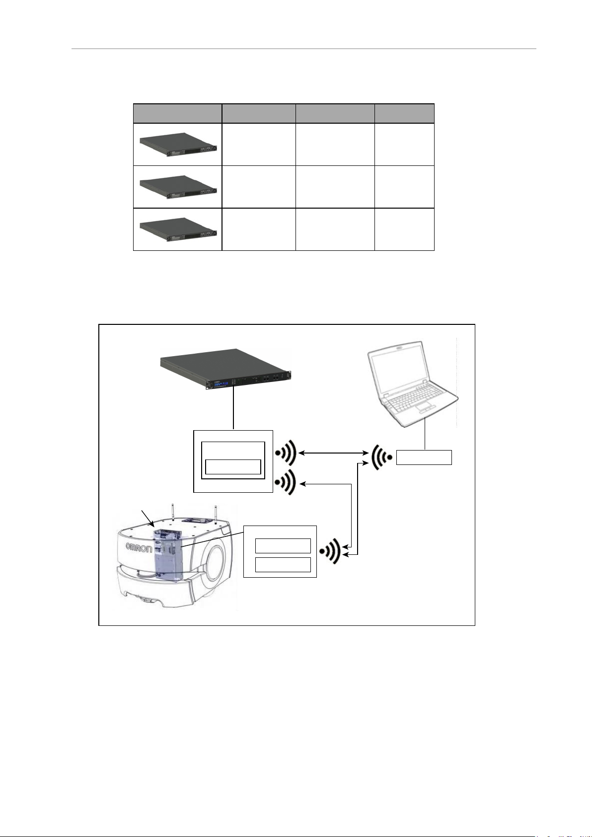
The figure below is a basic system architecture (for a fleet of AMRs) and illustrates the interrelationship between Fleet Operations Workspace Core’s various applications.
11 Fleet Operations Workspace Core User's Manual 20569-020 Rev. D
Figure 1-1. Components Working Together (LD-60 AMRShown)
Page 12
EM2100
The EM2100 is a network appliance, with built-in processor. It can be used to run the
FLOWCore fleet management software or the Fleet Simulator software. As a Fleet Manager, the
EM2100 coordinates the movement of up to 100 AMRs. It manages maps, AMR configurations, traffic control, and job queuing. FLOW Core licenses are activated on the Fleet Manager.
Version Information: Fleet Simulator support was added in FLOWCore version
1.1.
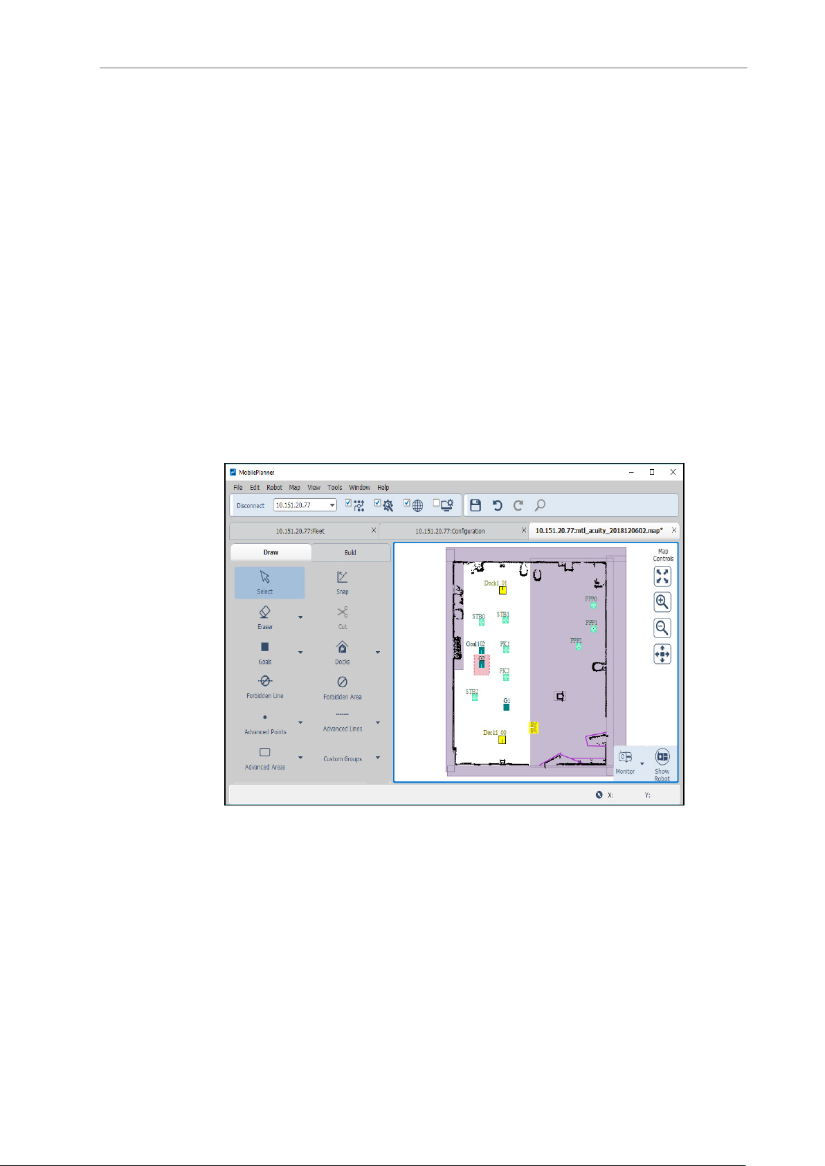
MobilePlanner
MobilePlanner is the graphical user interface (GUI) for communicating with and configuring
the AMR, and displaying and editing AMR map files. It is the "control center" of the Fleet Operations Workspace Core. Its user interface has the tools for all major AMR activities, such as
observing a fleet of AMRs, commanding individual AMRs to drive, creating and editing map
files, goals, and tasks, modifying AMR configurations, and more.
The AMRs use map files to determine where they are, plan navigable paths to goals, execute
tasks at programmed goals, and to control other AMR tasks.
Figure 1-2. MobilePlanner Interface
From the MobilePlanner interface, you can:
l
Connect to and drive the AMR.
l
Create maps of the environment by importing and analyzing an AMR’s scan data.
l
Edit maps by adding goals (and adding tasks to those goals), docks, forbidden areas,
and more. You can also erase stray or unwanted artifacts, combine pieces of maps, and
20569-020 Rev. D Fleet Operations Workspace Core User's Manual 12
Page 13
Chapter 1: Introduction
make other changes.
l
Download and upload files, including maps and scan data, to and from an AMR.
l
Set the system configuration parameters for the fleet.
l
With the Fleet Manager, monitor the location and status of all AMRs in a fleet.
l
View and interact with the job queuing manager.
For details, see MobilePlanner Interface on page 51.
MobilePlanner Accounts
User accounts with limited privileges provide the user with access to a limited set of tools for
monitoring AMR and AMR job status, and allow for simple interventions in job execution
sequences. For more information, see MobilePlanner Operator Account Overview on page 54.
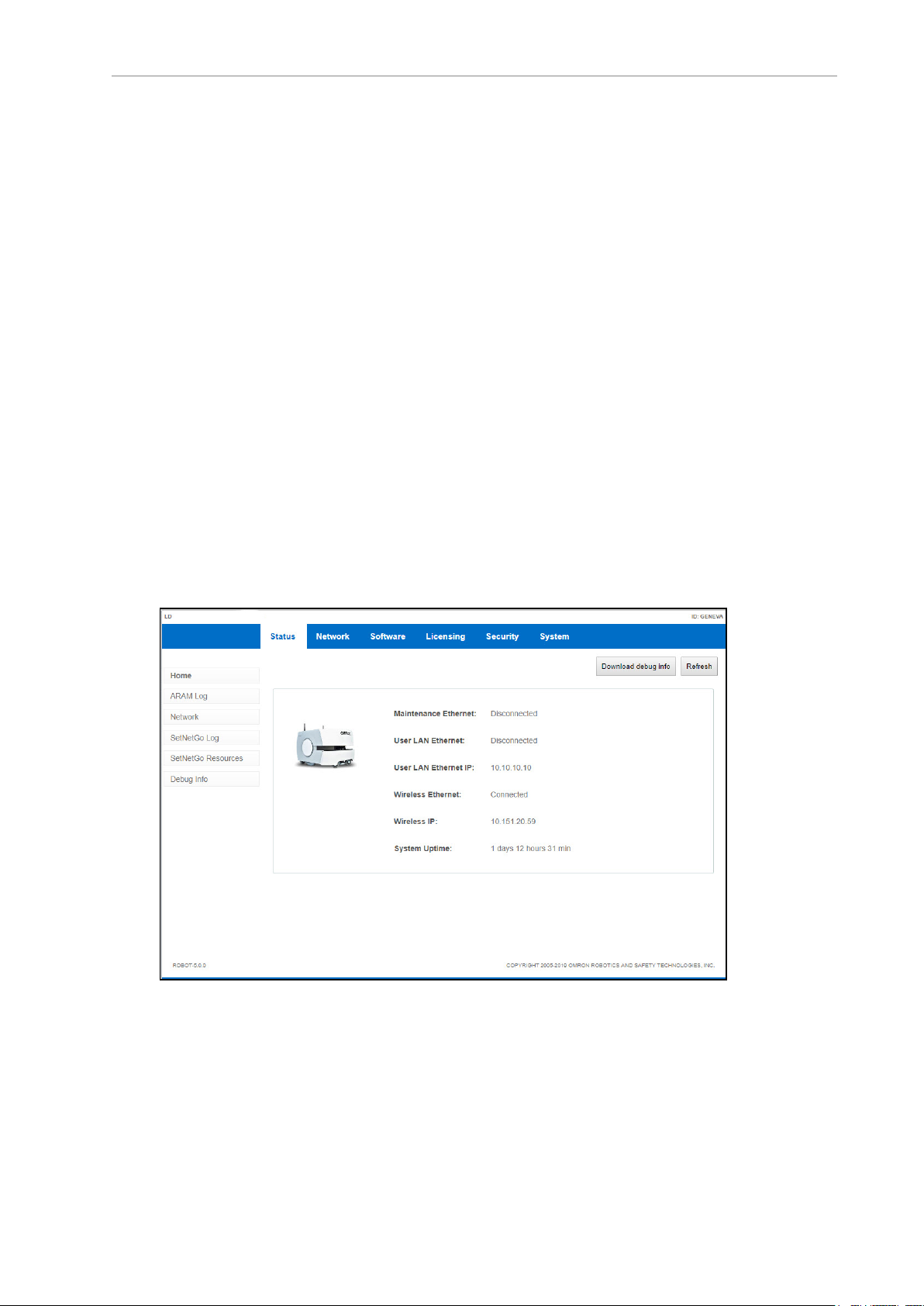
SetNetGo
SetNetGo is the operating system that resides on AMRs and the EM2100 appliance. You can
use the SetNetGo software to establish and configure your AMR's communication parameters,
access diagnostic information (for example, download debug info file for service provider use,
manage restore points, etc.), and perform software maintenance (upgrades). You most commonly access the SetNetGo interface through a tab in the MobilePlanner software, and then
use that interface to enable the parameters needed.
Figure 1-3. SetNetGo Interface
For details, see Overview of the SetNetGo OS on page 114.
NOTE: Optionally, you can connect to SetNetGo through a web browser. Refer
to Connecting to SetNetGo via web browser on page 115.
13 Fleet Operations Workspace Core User's Manual 20569-020 Rev. D
Page 14

ARAMCentral
As the fleet management software running on the EM2100 appliance, Advanced Robotics Automation Management (ARAMCentral) provides:
l
Centralized configuration and map management.
l
Job queuing and dispatch.
l
Traffic management.
l
Single-point of integration and communication for software clients and other automation equipment.
ARAM
The Advanced Robotics Automation Management (ARAM) software runs on the AMR's core,
and does the following:
l
Performs all the high-level, autonomous robotics functions, including obstacle avoidance, path planning, localization, and navigation, culminating in the AMR’s motion.
l
Manages wired and wireless Ethernet communications with off-board software, for
external monitoring, development, and systems coordination, including coordination of
a fleet of AMRs through the Fleet Manager.
l
Enables external monitoring and control with the MobilePlanner application.
MARC/Polo
Mobile Autonomous Robot Controller (MARC), which resides on the LD-series AMR core, manages the AMR’s speed and heading, sensor readings, emergency stop systems, bumpers, and
pendant. It also computes and reports the AMR’s odometry readings (X, Y, and heading) and
other low-level operations which it reports to ARAM.
Polo performs the same functions for the HD-1500 AMRs.
1.3 Fleet Operations Workspace Licensing
There are licensing options for both FLOW Core and advanced features. These licenses help
customers manage the costs of their AMR fleets through lower, annual subscription payments
for FLOW Core and activation of advanced features only if they provide benefits to your specific applications. The licenses currently available are listed in the following table. Contact
your OMRONrepresentative or Sales Office for pricing.
20569-020 Rev. D Fleet Operations Workspace Core User's Manual 14
Page 15

Chapter 1: Introduction
Table 1-2. Available Fleet Operations Workspace Licenses
Product License
Type
Primary Fleet
Management
Secondary Fleet
Management
Cell Alignment
Positioning System
(CAPS)
Fleet Simulator Perpetual
Subscription
Operating
License
Subscription
Operating
License
Perpetual
Feature
License
Feature
License
Product Description
License, 1 Yr Fleet Operations
Workspace Core, Primary
License, 5 Yr Fleet Operations
Workspace Core, Primary
License, 1 Yr Fleet Operations
Workspace Core, Secondary
License, 5 Yr Fleet Operations
Workspace Core, Secondary
License, High Accuracy cell alignment feature for OMRON AMRs
License, Fleet Simulator 20271-804
Model
20271-800
20271-806
20271-802
20271-807
20271-805
All of these licenses are field-upgradable. Section 7.6 shows the steps required to acquire or
update FLOW Core subscription, and Fleet Simulator and CAPS perpetual licenses.
1.4 How Can I Get Help?
For details on getting assistance with your OMRON software or hardware, you can access the
corporate website:
http://www.ia.omron.com.
If you need help beyond what is covered in the manual, contact your OMRONrepresentative.
15 Fleet Operations Workspace Core User's Manual 20569-020 Rev. D
Page 16

Related Manuals
Manual Description
Mobile Robot LD Safety Guide (Cat. No.
I616)
Mobile Robot HDSafety Guide (Cat. No.
I647)
LDPlatform OEMUser's Guide (Cat. No.
I611)
LD-250 Platform User's Guide (Cat. No.
I642)
HD-1500 Platform User's Manual (Cat.
No. I645)
LD Platform Peripherals Guide (Cat. No.
I613)
Mobile Robots - HD Platform Peripherals
Manual (Cat. No. I646)
EM2100 Installation Guide (Cat. No.
I634)
Fleet Operations Workspace Migration
Guide (Cat. No. I636)
Describes safety information for OMRON LDseries AMRs.
Describes safety information for OMRON HD1500AMRs.
Describes the installation, start-up, operation,
and maintenance of the LD-60 and LD-90
AMRs.
Describes the installation, start-up, operation,
and maintenance of the LD-250 AMR.
Describes the installation, start-up, operation,
and maintenance of the HD-1500 AMR
Covers peripherals for LD AMRs, such as the
Touchscreen, Call/Door box, and Acuity Localization options.
Covers peripherals for HDAMRs, such as
HAPS.
Describes the installation and initial configuration of an EM2100 appliance.
Describes the procedures for migrating your
AMR from legacy to FLOW Core software, and
from an EM1100 to an EM2100.
Fleet Operations Workspace Core Integration Toolkit User's Guide (Cat. No.
I637)
Fleet Simulator User's Manual (Cat. No.
I641)
Advanced Robotics Command Language
Enterprise Manager Integration Guide
(Cat. No. I618)
Describes specific tools to simplify integration
with factory equipment and material-movement solutions such as manufacturing execution systems (MES)and equipment
resource planning (ERP) solutions.
Describes the operation of the Fleet Simulator.
Describes the Advanced Robotics Command
Language (ARCL) version for use with the
EM2100 software. ARCL is a simple text-based
command and response server used for integrating the Fleet Operations Workspace Core
platform with an external automation system.
20569-020 Rev. D Fleet Operations Workspace Core User's Manual 16
Page 17

Page 18

Chapter 2: Safety and Regulatory Information
!
!
2.1 Safety and Regulatory
OMRON LD AMRs adhere to the following domestic and international safety regulations:
l
EN 1525 “Safety of Industrial Trucks. Driverless Trucks and their Systems”
l
ANSI 56.5:2012 “Safety Standard for Driverless, Automatic Guided Industrial Vehicles
and Automated Functions of Manned Industrial Vehicles”
l
JISD 6802:1997 “Automated Guided Vehicle Systems - General Rules on the Safety”
OMRON's HD-1500 AMRs are evaluated to the following standards:
l
EN ISO 10218-1
l
UL 1740
l
EN 60204-1
l
EN ISO 13849-1
2.2 Warnings, Cautions, and Notes
Where needed, this user guide calls out critical, important, or emphasized text via special alert
notifications. Below are explanations of the special alert notifications used in this manual:
WARNING: This indicates a potentially hazardous situation which, if not
avoided, will result in minor or moderate injury, or serious injury or death.
Additionally, there may be significant property damage.
CAUTION: This indicates a situation which, if not avoided, could result in
minor or moderate injury or in property damage.
IMPORTANT: Important indicates information that the user needs to know to
use the system correctly.
NOTE: Notes provide supplementary information, emphasize a point or procedure, or give a tip for easier operation.
Version Information: This indicates information that only applies to certain versions of software or hardware.
20569-020 Rev. D Fleet Operations Workspace Core User's Manual 18
Page 19

Chapter 2: Safety and Regulatory Information
2.3 General Safety Precautions
Read the installation and operation instructions, as well as the appropriate robot user's guide
and robot safety guide before using the equipment.
l
Do not ride on the AMR.
l
Do not exceed the AMR’s maximum weight limit.
l
Limit operation to areas with no slope.
l
Do not drop the AMR, run it off a ledge, or otherwise operate it in an irresponsible manner.
l
Do not get the AMR wet, or expose the AMR to rain or moisture. The AMR has an IP
rating of IP20.
l
Do not use power extension cords with the docking station unless properly rated.
l
Do not run the AMR if hair, yarn, string, or any other items are wound around the
AMR’s axles or wheels.
l
Never access the AMR’s interior with the charger attached. Immediately disconnect the
battery after opening the battery compartment door.
l
Never short the battery’s terminals together.
l
Do not use parts (including charging docks, etc.) not authorized by OMRON
2.4 Safety Commissioning
Safety standards require testing of the AMR's safety systems by a trained and qualified person,
both before leaving the factory and again at the customer's site.
Safety commissioning is executed from the MobilePlanner main menu. Access and execute the
safety commissioning procedure from MobilePlanner by selecting Robot > Safety Commissioning.
The safety commissioning procedure is guided by on-screen prompts. The instructions that
you see will be based on the type of robot that you have connected. The procedures will test
each E-Stop and Safety Laser on the AMR, as well as the E-Stop on the pendant. Details for
running these procedures are given in each AMR user guide.
2.5 What to Do in an Emergency
Press the E-Stop button (a red push-button on a yellow background/field) and then follow the
internal procedures of your company or organization for an emergency situation. If a fire
occurs, use a type D extinguisher: foam, dry chemical, or CO2.
2.6 Additional Safety Information
We provide more safety information in the following manual:
Mobile Robot LD Safety Guide (Cat. No. I616) and Mobile Robot
HDSafety Guide (Cat. No. I647)
The Mobile Robot LD Safety Guide (Cat. No. I616) and Mobile Robot HDSafety Guide (Cat. No.
I647) provide detailed information on safety for our AMRs. They also give resources for more
19 Fleet Operations Workspace Core User's Manual 20569-020 Rev. D
Page 20

information on relevant standards. A safety guide ships with each AMR.
20569-020 Rev. D Fleet Operations Workspace Core User's Manual 20
Page 21

Page 22

Chapter 3: Fleet Manager Configuration and
Operation
The Fleet Manager capabilitieswithin FLOWCore provide tools for programming and configuring individual AMRs and fleets, and for centralized job dispatch and real-time AMR monitoring within your facility.
3.1 EM2100 Configuration Overview
This section provides instructions for setting up and connecting the AMRs and Fleet Manager
to a network.
OMRON's EM2100 appliance provides the operating environment for the FLOW Core software. It will be the primary interface device to the network and any PC(s) running MobilePlanner. The EM2100 appliance comes pre-loaded with a temporary, 120 day, FLOW Core license,
which allows initial set-up, testing, and validation to begin immediately, without a full subscription license. A FLOW Core license must be purchased after the 120 day set-up period.
NOTE: The EM2100 can also run in the Fleet Simulator operating mode, with a
Fleet Simulator license. Refer to the Fleet Simulator User's Guide.
Configuration Tasks Overview
NOTE: This section assumes that you have read and followed the instructions
in the EM2100 Installation Guide (Cat. No. I634).
To configure the EM2100 appliance as a Fleet Manager, you must do the following tasks,
which are described in detail later in this guide:
l
Configure the network settings for the appliance Management Ethernet port.
l
Configure the network settings for the FLEET ETH2 Ethernet port.
l
Connect the Management and Fleet ports to the LAN.
l
Define the login information.
l
Configure each AMR to connect to the EM2100.
l
Customize each AMR, if desired.
If you install a Secondary EM2100 appliance and configure Autosync, you must also:
l
Install the same FLOWCore software version on the Secondary as is on the Primary
appliance.
l
Configure a unique IP address for the Management port.
l
Connect the Management port to the LAN.
l
Connect the FLEET ETH2 port to the LAN.
20569-020 Rev. D Fleet Operations Workspace Core User's Manual 22
Page 23

Chapter 3: Fleet Manager Configuration and Operation
l
Enter the Secondary Management IP address on the Primary appliance.
l
Generate and download a key from the Primary appliance.
l
Set the Secondary appliance Autosync role to Secondary.
l
Upload the key to the Secondary appliance.
l
Verify that the status of both appliances is active.
l
Create a direct network connection between the Primary and Secondary appliances.
3.2 Power Interruptions
Use the front momentary power switch to turn the EM2100 on and off. The rear power switch
should remain on unless you are uninstalling the appliance.
Power Interruptions on a Standalone EM2100
If there is an interruption to the power supply for any reason or duration, a standalone
EM2100 automatically returns to its previous power state.
l
A standalone appliance that was shut down and powered off when the interruption
occurred remains shut down after you restore power.
l
A standalone appliance that was powered on when the interruption occurred restarts
automatically after you restore power.
After recovery from a power interruption, the EM2100 saves its job queue status and recovers
the queue automatically after it restarts following a power failure. This does not apply to an
operator-initiated emergency power off. Refer to: Power Interruptions on page 23.
Power Interruptions on an Autosync Appliance
This section assumes that you configured Autosync on two EM2100 appliances and connected
each appliance to separate power circuits for redundancy. Providing that only one circuit was
affected, one appliance should remain operating normally during the power interruption. The
sequence of events and method of recovery depends on which appliance is affected:
A power interruption on the Primary appliance results in a loss of connectivity with
AMRs and MobilePlanner. You should:
l
Determine whether the problem is a power outage or a loss of network connectivity.
l
Manually reconfigure the Secondary appliance to become the Primary Appliance. Fleet
Management functions are restored but Autosync status is now disabled.
Autosync will need to be re-configured once the power issue with the original EM2100
appliance is resolved.
l
Verify that MobilePlanner and AMRs reconnect to the Fleet IP address.
l
Review the job queue status in MobilePlanner and verify the status of AMRs to make
sure that no jobs are incomplete.
l
Restore power to the former Primary appliance.
l
Change the former Primary appliance to a role of Secondary appliance.
23 Fleet Operations Workspace Core User's Manual 20569-020 Rev. D
Page 24

A power interruption on the Secondary appliance results in no loss of connectivity
with AMRs and MobilePlanner. You should:
l
Verify that MobilePlanner and AMRs are connected to the Fleet IP address.
l
Review the job queue status in MobilePlanner and verify the status of AMRs to make
sure that no jobs are incomplete.
l Restore power to the Secondary appliance. Autosync will be restarted if it was running
when the power was interrupted. Fleet operations should be unaffected.
If both Autosync appliances are affected by a power interruption, they both behave
as described in: Power Interruptions on a Standalone EM2100 on page 23:
l
All fleet operations are terminated during the power interruption.
l
Normal Active Autosync operation resumes automatically after you restore power to
both appliances.
l
The Primary EM2100 saves its job queue status and recovers the queue automatically
after it restarts. Autosync will reconnect automatically when power is restored.
3.3 Set the IP Address on a Client PC's Network Adapter
Use the Maintenance Ethernet port to connect a client PC to the SetNetGo operating system.
IMPORTANT: You must assign a static IP address. Do not use a DHCP server.
Configure the network adapter IPv4 address on the Client PC as follows:
1.
Connect an Ethernet cable from the client PC’s Ethernet port to the Maintenance Ethernet port on the EM2100 appliance.
2.
In the command field on the Windows taskbar, enter the following command to open
the Network Connections dialog: ncpa.cpl
3.
Open the network properties of the PC ethernet network adapter used to connect to the
Maintenance Ethernet port on the EM2100 appliance.
4. Double-click TCP/IPv4 to open the Internet Protocol properties dialog.
5.
Enter as the IP address: 1. 2. 3. 5, or any IP address in the range 1. 2. 3. 0 to 1. 2. 3. 255,
excluding 1. 2. 3. 4. (this is reserved for the Maintenance port).
6.
Enter as the subnet mask: 255. 255. 255. 0.
7.
Click OK to close the Internet Protocol dialog, and then click OK to close the Ethernet
Adapter dialog.
In future, you can use the Maintenance Ethernet port for emergency access to the Appliance at
IP address 1.2.3.4. (For example, if you lose the password or if there is a network IP address
conflict.)
3.4 Connect Your PC to SetNetGo on the EM2100
SetNetGo enables you to configure and manage EM2100 and AMRsettings. This section
describes how to access SetNetGo through the Maintenance port to perform initial configuration.
20569-020 Rev. D Fleet Operations Workspace Core User's Manual 24
Page 25

Chapter 3: Fleet Manager Configuration and Operation
The user interface for SetNetGo on an EM2100 provides a different set of parameters and
options compared to SetNetGo on an AMR. The upper left of the screen shows EM2100, LD,
LD-250, or HD depending on your SetNetGo context (the device on which it runs, such as the
OMRON LD-series AMRs).
Configure Access and Security
After you connect to the Maintenance Port as described in: Set the IP Address on a Client PC's
Network Adapter on page 24 you can open the SetNetGo web interface.
Connect your browser to SetNetGo and configure SetNetGo access as follows:
1.
In the SetNetGo web interface, click the Security Tab and then click SetNetGo Access
and check Enabled next to the following:
Maintenance Interface is automatically enabled.
l
Wireless Ethernet/User LANEthernet
l
(Optional) Remote Reboot.
2.
Change the account password (default is no password) as required and click Apply.
NOTE: Passwords are limited to a maximum of 20 alphanumeric characters.
For increased security, specify a long (10+ characters) password string with both
uppercase and lowercase letters. Include several digits.
3.5 Configure Management Interface Network Settings
To configure the Management Network, you require:
l A dedicated static IP address. (Do not use 1.2.3.4. That address is permanently assigned
to the Maintenance Ethernet port.)
l The subnet mask for the Management network.
l The IP address of the network Gateway.
l The IP address of a Domain Name Server (DNS) (this is only required if any hostnames
will be used in the Fleet Manager configuration), so that the Fleet Manager can resolve
all IP addresses.
Configure the Management Interface network connections as follows:
1.
In the SetNetGo web interface, click the Network tab.
2.
Click Management Interface and enter the:
a.
IP address.
b.
Subnet mask.
c.
Network Gateway IP address (typically a router).
3.
Enter the IP address of your Domain Name Server (DNS), if required for devices other
than the appliance and the fleet. Otherwise, leave it as 0.0.0.0.
4.
Click Apply.
25 Fleet Operations Workspace Core User's Manual 20569-020 Rev. D
Page 26

A message dialog informs you of the status of the change, and whether there is any affect on
operations such as a restart or a time delay before the change takes effect.
3.6 Configure the Operating Mode
Configure the Operating Mode as follows:
1.
In the SetNetGo web interface, click the System tab.
2.
Click Mode.
3.
Select the operating mode in which you will be using this EM2100.
The choices will be:
l
Unconfigured (this is how the EM2100 ships)
l
Standalone Fleet Manager
l
Paired Fleet Manager
l
Fleet Simulator
If a mode is greyed out, it means that you don't have the license to support that operating mode. Refer to Licensing Tab on page 126.
4.
Click Apply.
You will be shown several warning pop-ups. Respond OK to all.
The EM2100 will reboot.
At this time, Status > Home > Mode of Operation should show the operating mode
that you selected.
A message dialog informs you of the status of the change, and whether there is any effect on
operations such as a restart or a time delay before the change takes effect.
3.7 Configure the Fleet Interface Network Settings
To configure the Fleet Interface, you require:
l A dedicated static IP address to assign to the Fleet Interface port. This IP is allowed, but
not required, to be on the same subnet as the Management IP. Do not use 1.2.3.4,
because that address is permanently assigned to the Maintenance Ethernet port.
l The subnet mask for the network that your Fleet will use.
l The IP address of the network Gateway.
Configure the Fleet Interface network connections as follows:
1.
In the SetNetGo web interface, click the Network tab.
2.
Click Fleet Interface and enter the:
a.
IP address.
b.
Subnet mask.
20569-020 Rev. D Fleet Operations Workspace Core User's Manual 26
Page 27

Chapter 3: Fleet Manager Configuration and Operation
c.
Network Gateway IP address (typically a router).
3.
Click Apply.
A message dialog informs you of the status of the change, and whether there is any affect on
operations such as a restart or a time delay before the change takes effect.
27 Fleet Operations Workspace Core User's Manual 20569-020 Rev. D
Page 28
3.8 Configure Paired Appliances
The default (shipped) configuration for an EM2100 is Unconfigured. The user will need to configure it as either Standalone or Paired Fleet Manager.
To create an Autosync pair, refer to Configure the Primary Appliance on page 29 and Configure the Secondary Appliance on page 30. The paired appliances then function as follows:
l
The Primary unit is a fully-functional EM2100, running the Fleet Operations Workspace
Core and actively controlling the fleet.
l
The Secondary unit is powered on, with its web interface accessible to the Primary unit.
However, the fleet management functions are inactive on the Secondary unit, and it is
inaccessible from MobilePlanner or AMRs.
The Primary Fleet Manager has two active IP addresses, while the Secondary has only one active IP address.
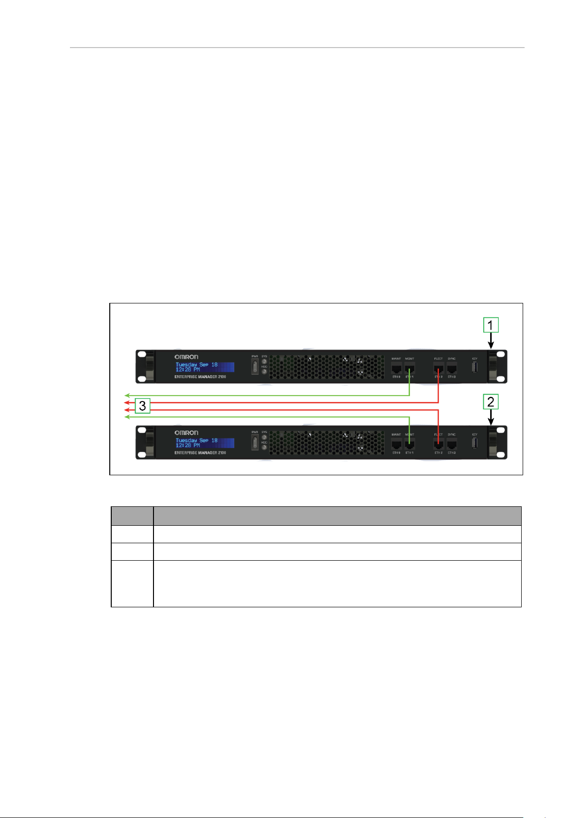
EM2100 Autosync — Ethernet Cabling
The following figure shows the physical connection of Ethernet cables to the appliances.
Figure 3-1. Cabling for an EM2100 Fleet Manager Pair
Callout Description
1 EM2100 configured as a Primary appliance.
2 EM2100 configured as a Secondary appliance.
3 Ethernet cables to the LAN switch:
l Primary and Secondary MGMT ETH1
l Primary and Secondary FLEET ETH2
Tasks in Autosync Setup
Before you set up Autosync, make sure that you have:
l
Installed the Primary appliance and connected it to the network.
l
Configured the Maintenance Ethernet interface on the Primary appliance.
20569-020 Rev. D Fleet Operations Workspace Core User's Manual 28
Page 29
Chapter 3: Fleet Manager Configuration and Operation
l
Physically installed the Secondary appliance hardware, as described in the EM2100
Installation Guide.
The tasks required to set up autosync between a Primary and Secondary appliance are:
l
Configure the Primary appliance with a Fleet IP Address.
l
Enter the Secondary appliance IP Address in the Primary appliance.
l
Generate and Download the Primary key (to your PC).
l
Set the Secondary appliance Autosync role to Secondary.
l
Upload the Primary key to the Secondary appliance.
Configure the Primary Appliance
Do this only if you have two Fleet Manager appliances, and you want to configure one as a
Primary Fleet Manager. You must first configure the Management and Fleet networks and
cable the appliances.
1.
In the SetNetGo web interface, click the System tab, then Mode.
2.
Select Paired Fleet Manager from the drop-down menu. Click Apply.
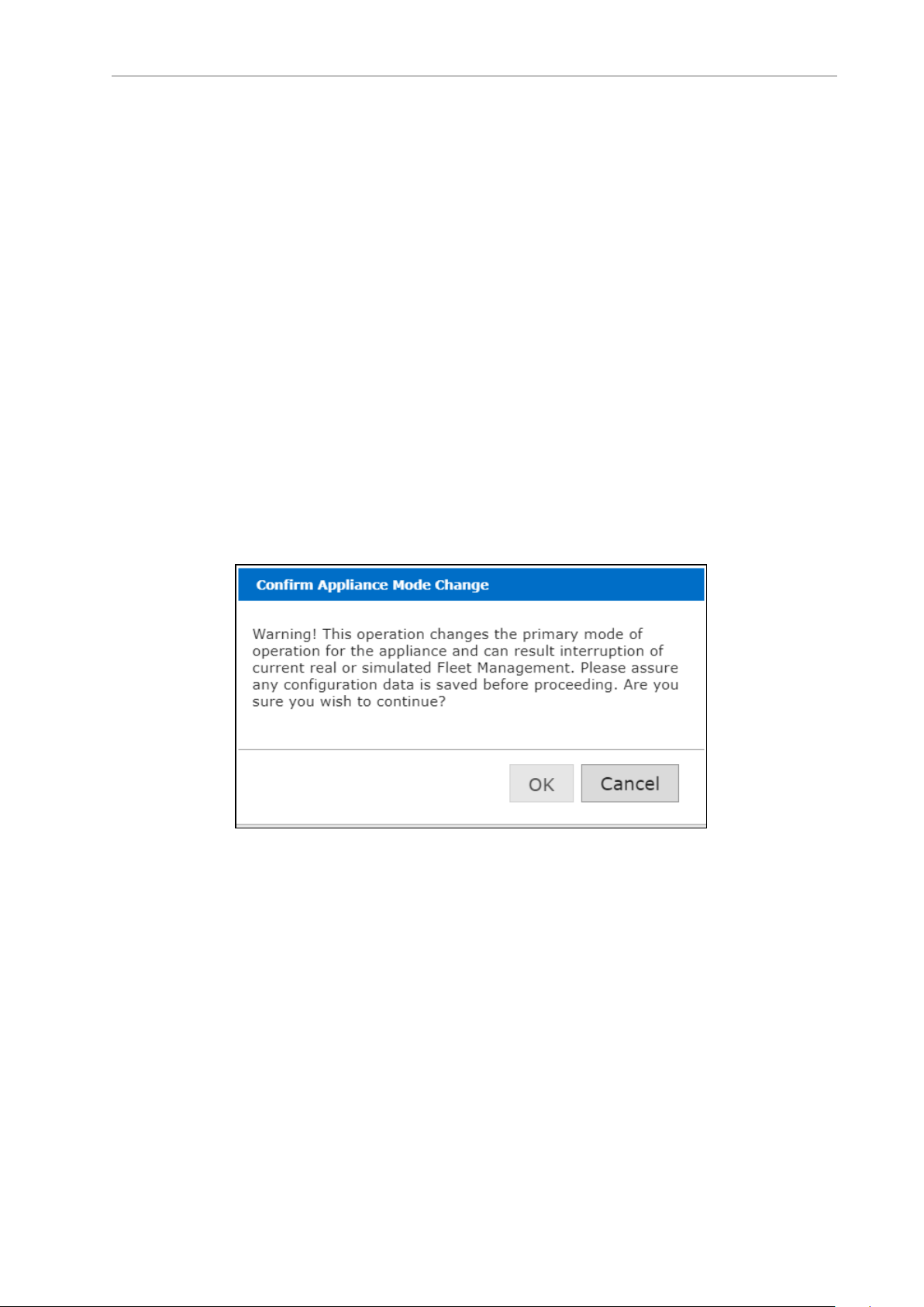
You will get a "Confirm Appliance Mode Change" pop-up message.
Figure 3-2. Confirm Appliance Mode Change Window
3.
Click OK.
You will get a second pop-up with a warning that this operation will interrupt the
fleet management.
4. Click OK.
5.
Click the Pairing button that appears in the left margin of the screen.
6.
From the drop-down menu next to the Pairing Role, select Primary, and click Apply.
7.
Enter the IP Address of the Secondary appliance. Click Apply.
29 Fleet Operations Workspace Core User's Manual 20569-020 Rev. D
Page 30
8.
You will get a message to confirm changes, saying that ARAMCentral will restart, disconnecting AMRs and clients. Click OK.
9.
You will get a confirmation message that the changes were successfully applied. Click
OK.
10.
Click Generate New Key to create an SSL key, or Download Existing Key, if you pre-
viously created an SSL key.
Uploading the SSLkey to the Secondary appliance grants permission for the Primary
to perform RPC calls required for synchronization.
11.
You are prompted for a location to save the key file. Enter a location (path) where you
want to save the file on your PC, so you can later upload it to the Secondary appliance.
12.
A warning message indicates the pending disconnection of AMRs and clients. Click
OK.
Your Primary Fleet Manager is now configured to run as part of a pair.
Configure the Secondary Appliance
Do this only if you have two Fleet Manager appliances, and you want to configure one as a
Secondary Autosync appliance. You must first:
1.
In the SetNetGo web interface, click System tab, then Mode.
2.
From the drop-down menu choose Paired Fleet Manager and click Apply.
3.
You will get a "Confirm Appliance Mode Change" pop-up message. Click OK.
4.
You will get a second pop-up with a warning message that this operation will interrupt
the fleet management. Click OK.
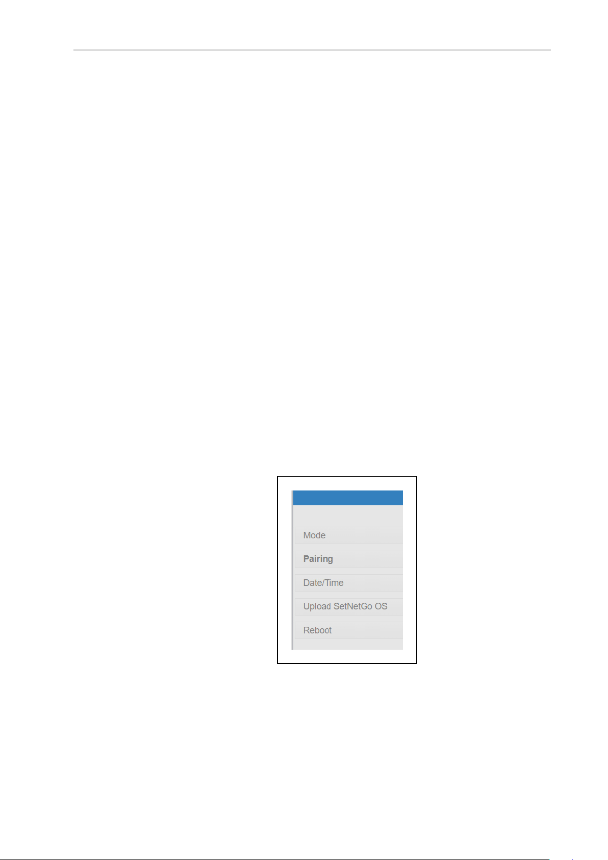
5.
A Pairing selection will appear in the left margin of the screen. Click on Pairing.
Figure 3-3. Pairing Selection, Left Bar
6.
From the drop-down menu, next to the Pairing role, choose Secondary. Click Apply.
20569-020 Rev. D Fleet Operations Workspace Core User's Manual 30
Page 31

Chapter 3: Fleet Manager Configuration and Operation
You will get a Confirm changes message that ARAMCentral will halt, disconnecting
AMRs and clients. Click OK.
7.
You will get a confirmation message that the changes successfully applied. Click OK.
Figure 3-4. Changes Successfully Applied Window
8.
Click Choose File to select the Primary SSLkey from your PC to chose the proper file.
Enter the name and path of the file to upload the key from the PC.
9.
Click Upload.
Your appliance is now configured as a Secondary appliance.
NOTE: Although the Fleet Interface settings are saved for the Secondary appliance, the interface is inaccessible.
When the connection is complete, the Primary and Secondary appliances show a Current
Status of active.
3.9 Configure Each AMR to Connect to the Fleet Manager
Before you can use the Fleet Manager appliance to manage AMRs, you must configure each
AMR to connect to the appliance. To do so, you must connect to each AMR.
When an AMR connects to the appliance, the Fleet Operations Workspace Core overwrites the
AMR's configuration parameters with Fleet parameters.
AMR Configuration Settings
To connect an AMR to the EM2100 appliance:
1.
Launch MobilePlanner on your client PC and connect to the AMR's IP address.
If this is a new AMR, its IP address will be the factory setting of 1.2.3.4 for LD-series
AMRs, and 169.254.10.15 for the HD-1500 AMR. The connection must be hard-wired,
because the AMR's wireless won't be configured yet.
2.
Open the Config tab.
31 Fleet Operations Workspace Core User's Manual 20569-020 Rev. D
Page 32

3. Check Show Expert Parameters to show the advanced configuration parameters.
4.
From MobilePlanner, Config select Fleet and then Fleet Manager Connection.
Figure 3-5. Fleet Manager Connection Screen
5.
Check the ConnectToFleetManager checkbox.
6.
Enter the IP address of the EM2100 appliance in the
FleetManagerAddress field.
NOTE: This is the Fleet IPaddress, not the Management IP address of the
EM2100.
7.
Enter an identifier in the Identifier field. You must use unique identifiers for each AMR.
Do not change this identifier after initial setup.
Repeat these steps for each AMR that you want to add to the fleet controlled by this EM2100
Fleet Manager.
Fleet-Level Settings
From MobilePlanner, Config, on the Fleet Manager:
1.
Select Fleet and then Fleet Features.
2.
Check the FleetManagerGatherScans box.
This enables Fleet Operations Workspace Core to gather any scan files created by the
AMRs.
3.
Back up (copy) any required maps to a storage location.
4.
[OPTIONAL] Check DeleteUnusedMaps to permanently delete unnecessary map files
from each AMR.
20569-020 Rev. D Fleet Operations Workspace Core User's Manual 32
Page 33

Chapter 3: Fleet Manager Configuration and Operation
3.10 What to do if a Primary Fleet Manager Fails
This section applies only if you installed a second EM2100, autosynchronized with the
Primary Fleet Manager.
In event of failure:
1.
Using the SetNetGo interface, connect to the Management IP address for the Secondary
Fleet Manager EM2100 appliance.
2.
Click Apply (or click Reset to retain the previous values without your changes).
The AMRs automatically reconnect to the new Primary appliance.
The queue, configuration, and map data on the new Primary is identical to that of the old
Primary, prior to failure. Depending on exact network configuration, it takes between 1-3
minutes for AMRs to reconnect and resume operation.
The original (failed) Primary appliance can now be safely removed from the rack without causing disruption to the fleet. The following considerations apply:
l
The new Primary operates on the same Fleet IP as the old Primary appliance. Do not
reconnect the old Primary to the network without first reconfiguring it. Doing so might
cause a network IP conflict.
l
The failed Primary has the queue file, which is no longer current. Before putting the
failed Primary back into service, you should manually clear the queue. See Manually
Clearing (Flushing) the Entire Queue on page 200.
3.11 Remove and Replace EM2100 Appliances from Autosync
This section describes how to remove an appliance from an Autosync configuration.
Remove a Primary Fleet Manager Appliance from Autosync
You might need to remove a Primary Fleet Manager appliance from an Autosync configuration while maintaining fleet operations. For example, if the Primary appliance is generating errors that indicate a potential failure or degraded performance. This procedure
assumes that you do not make any changes to the software and data stored on the removed
appliance.
To safely remove an EM2100 Primary Fleet Manager appliance from an Autosync configuration, you must promote the Secondary appliance to the Primary role as covered in the
previous section. You can then safely remove the Primary as follows:
1.
Verify that fleet operations are normal and job processing is on schedule.
2.
Reconfigure the Primary appliance as a Secondary appliance. See: Configure the Secondary Appliance on page 30.
MobilePlanner and fleet AMRs might lose their network connection to the appliance.
3.
Reconfigure the Secondary appliance as the Primary appliance. See: EM2100 Configuration Overview on page 22.
4.
Power off the Secondary appliance.
5.
The Status tab in SetNetGo will now show that Autosync for the new Primary appliance
33 Fleet Operations Workspace Core User's Manual 20569-020 Rev. D
Page 34

is disabled (it is now a standalone appliance).
6.
Verify that MobilePlanner can connect to the Fleet IP, that fleet AMR operations resume,
and jobs are processed as scheduled.
To restore a removed EM2100 appliance or to replace it with a new appliance, it should be put
into the role of Secondary Fleet Manager, not Master. This will cause less disruption to the
fleet.
Remove a Secondary Fleet Manager from Autosync
You might need to remove a Secondary Fleet Manager appliance from an Autosync configuration while maintaining fleet operations. For example, if the Secondary Fleet Manager
appliance is generating errors that indicate a potential failure or degraded performance. This
operation is less disruptive than removing a Primary Fleet Manager.
IMPORTANT: This procedure assumes that you do not make any changes to
the Fleet Manager configuration or to the software and data stored on the appliance.
To remove a Secondary Fleet Manager appliance from an Autosync configuration:
1.
Verify that fleet operations are normal and job processing is on schedule.
2.
Power off the Secondary Fleet Manager appliance.
If a soft shutdown doesn't work, use a hard shutdown. Refer to the EM2100 Installation
Guide for details on hard- vs. soft-shutdowns.
3.
Verify that MobilePlanner can connect to the Fleet IP, that fleet AMR operations continue, and that jobs are processed as scheduled.
To restore a removed Secondary Fleet Manager appliance:
1.
Verify that fleet operations are normal and job processing is on schedule.
2.
If you have removed any network cables, reinstall them. Configure Paired Appliances
3.
Power on the Secondary Fleet Manager appliance. (This should not affect fleet operations or Ethernet connections to MobilePlanner and AMRs.)
Both appliances now indicate that Autosync is Active.
If no changes have been made to the configuration, the Secondary appliance will come
back up as a Secondary, but the Primary will be running as a Standalone.
4. Reconfigure the Primary appliance to be paired with the Secondary. See Configure the
Primary Appliance on page 29.
20569-020 Rev. D Fleet Operations Workspace Core User's Manual 34
Page 35

Page 36

Chapter 4: Fleet Operations Workspace Core
Software
The Fleet Operations Workspace Core (FLOWCore)software has the tools and features to help
you get your AMR up and running quickly. This chapter covers the initial steps needed to
access your AMR with the PCand to begin using the Fleet Operations Workspace Core software.
20569-020 Rev. D Fleet Operations Workspace Core User's Manual 36
Page 37

Chapter 4: Fleet Operations Workspace Core Software
4.1 How Do I Begin?
Before you can start using your AMR, there are a number of initial set-up and configuration
steps you need to complete.
NOTE: It is assumed that, prior to beginning fleet programming with FLOW
Core, all AMRs and EM2100 appliances being used in the fleet have been
unpacked, installed and set-up according to their respective user guides.
Procedure Reference
Install the MobilePlanner software on your PC. Install the MobilePlanner Software on page
39
Connect your PC to the AMR via Ethernet cable. Step 1: Connect Your PCto the AMR via Eth-
ernet on page 41
Configure the AMR for wireless communication. Step 4: Configure Your AMR's Network and
Security Settings on page 47
Establish a wireless connection to the AMR. Step 5: Connect to the AMR Wirelessly on
page 48
Scan the AMR's environment. Scanning the Operating Area on page 88
Convert the scan to a map. Convert the Scan into a Map on page 89
Use MobilePlanner software to edit (erase stray
and other dynamic features from) the map.
Add docks, forbidden zones, goals, and route(s)
between goals, etc. to the map.
Save the edited map on the AMR. Saving the Map on the AMR on page 108
Localize the AMR. Set the AMR's Initial Location on page 111
Create some tasks, and have the AMR
begin performing them.
Editing a Map File on page 93
Working with Map Files on page 90
AMR Tasks on page 150
4.2 End-User License Agreement (EULA)
Users will be presented with and must agree to the End User License Agreement (EULA) in
order to access and use any of the FLOW Core software content and functionality.
Definitions
l
An End User is the person, company, or organization that actually uses the software
and OMRON Mobile Robotics equipment.
l
System Integrators are not End Users when they are installing OMRON Mobile Robotics solutions for another business.
l
System Integrators are End Users when they own and install OMRON Mobile Robotics
solutions for their own use (e.g. for test or demonstration fleets).
37 Fleet Operations Workspace Core User's Manual 20569-020 Rev. D
Page 38

The Click-to-Accept (CTA) EULA will pop up:
l
When the FLOW Core software is installed.
l
Whenever the FLOW Core software is updated.
l
Upon first launching SetNetGo software (Out Of the Box).
l Whenever the SetNetGo software is updated.
l
Whenever a V2C (license) file is uploaded (first time, updates, and renewals).
New entitlements are not required when existing dongles are transferred from a failed
EM2100 or AMR to new EM2100 or AMR hardware. Therefore, no EULA is required in
these cases.
l
Whenever a new user-facing language is selected (in order to ensure delivery of the CTA
EULA in the appropriate language).
Once the CTA EULA Prompt is Triggered
1.
The CTA EULA pop-up will display in the language that matches the software
installed.
2.
The User must scroll through the entire End User License Agreement before the Accept
button is enabled (this button is greyed-out until then).
3.
The User must check either "End User" or "Manufacturer or System Integrator" before
the Accept button is enabled.
Accepting as "End User" will stop the CTA from re-triggering upon launching the software. All other triggers will still prompt user with the CTA pop-up.
Accepting as "Manufacturer or System Integrator" will not stop the CTA from re-triggering upon launching the software. This is to ensure that the End User gets prompted
when first launching the software "out of the box".
4.
The User can either click Accept, or abort the process.
Aborting the CTA EULA process will cancel and close out of the process that triggered
the CTA EULA pop-up (V2C Upload, Language Change, Software Update, Software
Install, First-Time/Out Of the Box Software Start Up).
In this case, the User can re-trigger the CTA EULA prompt by initiating one of the trigger processess listed above.
5.
If the software license is activated at the factory, in the Fleet Simulator bundle for
example, the CTA EULA pop-up will be displayed and a selection must be made prior
to the Simulator performing its intended functions.
The intent here is that the Fleet Simulator should be able to connect to SetNetGo and
MobilePlanner but no configuration or simulations can be run until the user clicks the
Accept button.
20569-020 Rev. D Fleet Operations Workspace Core User's Manual 38
Page 39

Chapter 4: Fleet Operations Workspace Core Software
Capturing CTA Interactions
1.
Every time the CTA EULA process is initiated and completed, the following data shall
be captured and logged:
l
What triggered the CTA EULA prompt (e.g "Software Update", "V2C Upload",
etc.)
l
Date/Time CTA EULA process was triggered
l
Date/Time CTA EULA process was completed
l
Whether CTA EULA was Accepted, or the process was aborted (either of these
will be considered as completed.
2.
Users can access a reference log file, but will not have access to or the ability to make
changes to the source data populating these logs.
NOTE: The Click-to-Accept EULA functions only apply to the FLOW Core software. There is no impact on the Legacy MSS 4.X software.
4.3 Install the MobilePlanner Software
Before setting up a wireless connection to your AMR, you will need to install MobilePlanner
on your PC. This software is the primary interface to the Fleet Manager and AMRs, and allows
programming of the AMR fleet.
System Requirements
Verify that your PC meets the following requirements before installing MobilePlanner:
l OS: Windows 7 (32-bit/64-bit), Windows 8 (32-bit/64-bit),or Windows 10 (32-bit/64-bit).
l CPU: 1.5 GHz Dual-core (min).
l RAM: 1.5 GB (min) 4 GB RAM recommended).
l GPU: 256 MB (min).
l HDD/SSD: At least 250 MB available space.
l Monitor: XGA 1024 x 768.
Installing MobilePlanner
Ensure that your PC meets the system requirements, then install (or download and install)
MobilePlanner.
NOTE: The MobilePlanner software installs into a MobilePlanner5 directory.
This different install directory allows you to use the relevant MobilePlanner version with your fleet.
Version Information: Only MobilePlanner software version 5 or higher is compatible with FLOW Core. It is not compatible with OMRON fleets running on
Mobile Software Suite version 4.X or earlier. Refer to https://automation.omron.com for release notes or contact your OMRONrepresentative for
more information.
39 Fleet Operations Workspace Core User's Manual 20569-020 Rev. D
Page 40

1. Use one of the following methods to locate and/or install the MobilePlanner software:
a.
By USB drive: insert the software media(USB drive included with your AMR’s
documentation) into your PC, and browse to the USBdrive to locate and install
the software.
From your EM2100: Open SetNetGo > Software >Manage Installed Software
>MobilePlanner > It can be downloaded here. (Click on the "here" link in the
EM2100 user interface, shown near the bottom of the following figure.)
Figure 4-1. Manage Software Download
b.
c.
By download: Contact your OMRONrepresentative for assistance with down-
loading MobilePlanner software.
To download MobilePlanner from the internet, access www.robotics.omron.com
or contact your OMRONrepresentative.
2.
Launch the installer and, when the welcome screen appears, follow the prompts in each
installation wizard window to complete the installation.
If you used SetNetGo or downloaded the software, this will usually be in your Downloads folder. The actual location is determined by the settings in the browser that you
use.
3.
Click Finish when done.
20569-020 Rev. D Fleet Operations Workspace Core User's Manual 40
Page 41

Chapter 4: Fleet Operations Workspace Core Software
4.4 Configure the AMR’s Wireless Communications
Before you can start working with your AMR, you have to configure it for wireless communication (via WiFi) using your PC. To do this, you will first have to connect your PC to the
AMR via Ethernet cable to gain access to the AMR's wireless settings. In general, the set-up
process is as follows:
l Connect your PC to the AMR via Ethernet
l Set your PC’s IP address
l Connect to SetNetGo
l Configure the AMR’s network settings
l Establish a wireless connection to the AMR
NOTE: The setup steps above assume that the AMR is fully-charged, powered
up, and ready. If this is not the case, please refer to your AMR’s user guide for
complete setup instructions.
Step 1: Connect Your PCto the AMR via Ethernet
To connect your PC to the AMR:
1.
Open the AMR's maintenance access panel (left side, upper right corner), by pressing
the access panel’s upper left corner (see image below) into the side of the AMR.
Figure 4-2. Maintenance Door Location
2.
Using a standard (pass-through) or cross-over Ethernet cable, connect your PCdirectly
to the AMR's maintenance Ethernet port. Refer to the following three figures. The AMR
will auto-detect the cable type.
41 Fleet Operations Workspace Core User's Manual 20569-020 Rev. D
Page 42
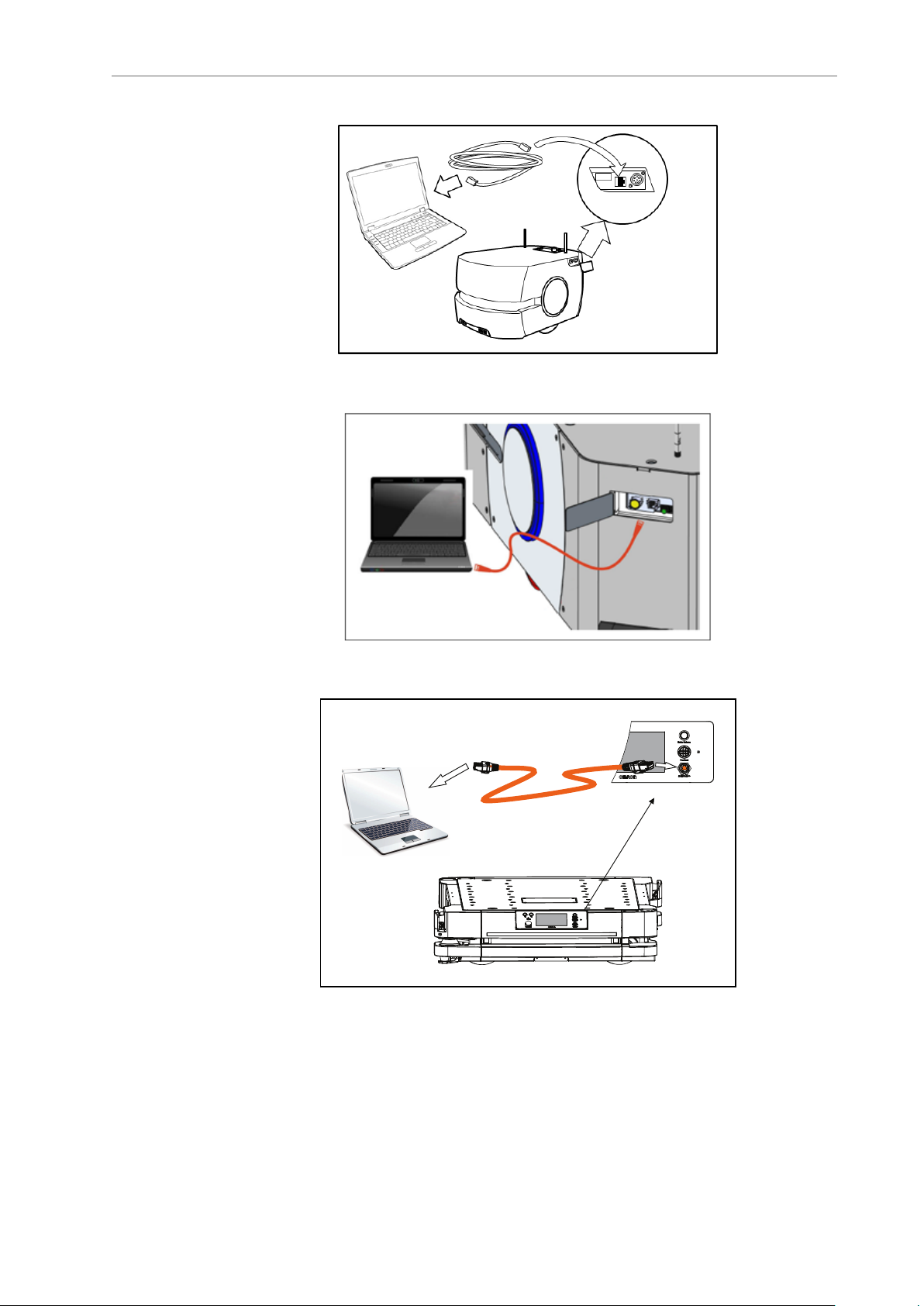
Figure 4-3. Maintenance Port Connection, LD-60 and LD-90
Pendant
Figure 4-4. Maintenance Port Connection, LD-250
Figure 4-5. Maintenance Port Connection, HD-1500
20569-020 Rev. D Fleet Operations Workspace Core User's Manual 42
Page 43

Chapter 4: Fleet Operations Workspace Core Software
Step 2: Set the IPAddress on Your PC
In order to configure WiFi on your AMRs, the LD-series AMRs and the HD-1500 AMRs are
accessed differently. If you have a combination of the two, we suggest that you set up all of the
LD-series AMRs and all of the HD-1500 AMRs as two separate procedures.
LD-Series AMR IPAddress Setup
Manually set your PC’s Ethernet port IP address to 1.2.3.x, where x is any number 1 - 254,
except 4 (which the AMR uses), and a Subnet mask of 255.255.255.0. No special DNS or gateway settings are needed.
NOTE: The LD-series AMR's maintenance Ethernet port is always enabled and
permanently set to IP address 1.2.3.4, with a Subnet mask of 255.255.255.0, for
direct, wired access to the on-board systems.
1. Open your PC's Network Connections window.
2.
Right-click on your PC’s Local Area Connection Ethernet connection, and select Prop-
erties.
Figure 4-6. Windows Local Area Connection Properties Dialog
3.
In the Local Area Connection Properties dialog box, click on the TCP/IP protocol your
network uses (for example, Internet Protocol Version 4 (TCP/IPv4)), then click Prop-
erties.
43 Fleet Operations Workspace Core User's Manual 20569-020 Rev. D
Page 44

Figure 4-7. Windows Internet Protocol Properties Dialog
4. In the TCP/IP properties dialog box, click the Use the following IPaddress: radio button
and enter an appropriate IPaddress (for example, 1.2.3.5) and Subnet mask
255.255.255.0.
5. Click OK.
6. Close the Network Connections window.
HD-1500 AMR IPAddress Setup
To enable DHCP or change other TCP/IP settings (Windows 10)
1.
Select Start, then select Settings > Network & Internet.
2.
Do one of the following:
l
For a Wi-Fi network, select Wi-Fi > Manage known networks. Choose the net-
work you want to change the settings for, then select Properties.
l
For an Ethernet network, select Ethernet, then select the Ethernet network you’re
connected to.
3.
Under IP assignment, select Edit.
4.
Under Edit IP settings, select Automatic (DHCP) or Manual.
To specify IPv4 settings manually (IPv6 is not supported)
a.
Under Edit IP settings, choose Manual, then turn on either IPv4.
b.
To specify an IP address, in the IP address, Subnet prefix length, and Gateway
boxes, type the IP address settings.
20569-020 Rev. D Fleet Operations Workspace Core User's Manual 44
Page 45

Chapter 4: Fleet Operations Workspace Core Software
c.
To specify a DNS server address, in the Preferred DNS and Alternate DNS
boxes, type the addresses of the primary and secondary DNS servers.
l
When you select Automatic (DHCP), the IP address settings and DNS server
address setting are set automatically by your router or other access point (recommended).
l
When you select Manual, you can manually set your IP address settings and
DNS server address.
5.
When you’re done, select Save.
Step 3: Access SetNetGo Software
The SetNetGo software lets you manage a variety of settings related to the AMR's connectivity.
You can access SetNetGo from MobilePlanner (most common), or a secure web browser (for
example, Chrome, Firefox, or Internet Explorer).
To Access SetNetGo from MobilePlanner
NOTE: Only start the following procedures if your computer is connected to the
AMR via Ethernet cable.
1.
Open the MobilePlanner software.
2.
For an LD-series AMR, enter 1.2.3.4 into the AMR address field, then click Connect.
For an HD-1500 AMR, enter 169.254.10.15 into the AMR address field, then click Con-
nect.
3.
Click the SetNetGo button (the large part of that icon, not the checkbox).
4.
Click the SetNetGo tab.
To Access SetNetGo via Web Browser
1. Start a web browser on your computer.
2.
Enter the URL https://1.2.3.4 in the address bar of the web browser.
This is the AMR’s maintenance Ethernet address. When accessing the software from a
wired maintenance Ethernet port, you do not need a username or password.
Figure 4-8. Browser Address Field
NOTE: You can ignore the certificate error that appears on the SetNetGo webpage; the error appears because the hardware is not attached to the Internet.
45 Fleet Operations Workspace Core User's Manual 20569-020 Rev. D
Page 46

The SetNetGo startup screen is shown the following figure.
Figure 4-9. SetNetGo Interface
20569-020 Rev. D Fleet Operations Workspace Core User's Manual 46
Page 47

Chapter 4: Fleet Operations Workspace Core Software
Step 4: Configure Your AMR's Network and Security Settings
To access your AMR remotely, you should set up a static IP address for each AMR. The
SetNetGo interface allows you to configure your hardware’s Ethernet settings, configure serial
and TCP forwarding, and upgrade the on-board software. If you are not familiar with setting
up a network or do not have an assigned IPaddress for the AMR, please see your system
administrator.
IMPORTANT: If you change any values in a SetNetGo screen, you must click
Apply before switching to another sub-screen, or those values will not be saved.
For example, when changing wireless Ethernet settings, be sure to click Apply
before navigating back to the dashboard.
To configure network settings, click the Network tab at the top of the SetNetGo screen.
Figure 4-10. SetNetGo Interface
Network
Menu
Wireless
Ethernet
User LAN
Ethernet
RS-232 Port
Forwarding
Sets up your wireless Ethernet connection to your AMR, including
IPsettings, WiFi network settings, security settings, and radio settings.
This screen has user-configurable settings for interface mode, IP
address, netmask, DHCP server for accessories, and DHCP IP range.
Controls forwarding of serial data to a TCP port on the wireless and
internal wired Ethernet networks, where the data is re-directed to a
TCP port on an IP address accessible via the Wired Ethernet interface
(which must be set to accessory mode). There is also port-forwarding
for the two extra on-board serial ports to a TCP port on the wireless Ethernet interface.
Description
47 Fleet Operations Workspace Core User's Manual 20569-020 Rev. D
Page 48

Network
Menu
Description
Ethernet
Forwarding
Utilities
Set the Username and Password to secure access to the AMR
Use the settings on this screen to control TCP port forwarding from
your User LAN Ethernet interface to the wireless Ethernet interface.
Use this screen to ping an IP address for testing and diagnostic purposes.
You must add one or more users, and assign usernames and passwords. Click the Security
tab, then click the Enabled radio button and populate the username/password fields (see Setting Up User Accounts on page 132).
Step 5: Connect to the AMR Wirelessly
Now that you have installed the Fleet Operations Workspace Core and configured the AMR for
wireless communications, connect to your AMR.
1.
(If not already running) double-click the MobilePlanner icon on your PCdesktop.
Figure 4-11. MobilePlanner Desktop Icon
20569-020 Rev. D Fleet Operations Workspace Core User's Manual 48
Page 49

Chapter 4: Fleet Operations Workspace Core Software
Figure 4-12. MobilePlanner Interface
NOTE: If running MobilePlanner from an Operator account, the interface
will look slightly different than above.
By default, the Fleet, Config, and Map buttons have checkmarks indicating those features will automatically load when you connect to the AMR.
2.
In the Connect field, enter the IPaddress of the AMR, then click Connect.
3.
Enter User Name and Password in the User Name and Password dialog box, then click
OK.
NOTE: If the SetNetGo button is checked, this User Name and Password
dialog appears.
A login dialog appears in which you must enter a user name, password, and AMR
server IPaddress.
NOTE: After connecting to the AMR the first time, MobilePlanner remembers your user name. When connecting to the AMR again, you can select
your user name from a combo box instead of having to re-enter, but you
must still enter your password.
MobilePlanner completes its connection to the AMR. At this point, there is no map to load, so
MobilePlanner opens with a blank map window.
49 Fleet Operations Workspace Core User's Manual 20569-020 Rev. D
Page 50

Chapter 5: Using MobilePlanner Software
The MobilePlanner software is the "control center" of the Fleet Operations Workspace Core. Its
user interface has the tools for all major AMR activities, such as observing a fleet of AMRs,
commanding individual AMRs to drive, creating and editing map files, goals, and tasks, modifying AMR configurations, and more.
The following topics provide details on understanding and using the MobilePlanner features.
5.1 Overview of MobilePlanner
MobilePlanner has features you can use to scan the AMR environment, configure the AMR,
create and edit maps, and more. The interface is designed to be user-friendly and efficient,
which reduces the learning curve and the time needed for deployment.
The MobilePlanner interface supports the following languages:
l English l Italian
l French l Korean
l German l Simplified Chinese
l Japanese l Traditional Chinese
l Spanish
Table 5-1. MobilePlanner User Interface (with Map)
NOTE: While MobilePlanner is not necessary for each AMR, you must have at
least one copy of MobilePlanner to create a map.
20569-020 Rev. D Fleet Operations Workspace Core User's Manual 50
Page 51

Chapter 5: Using MobilePlanner Software
From the MobilePlanner interface, you can:
l
Connect to and drive the AMR.
l
Create maps of the environment by importing and analyzing an AMR’s scan data.
l
Edit maps by adding goals (and adding tasks to those goals), docks, forbidden areas,
and more. You can also erase stray or unwanted artifacts, combine pieces of maps, and
make other changes.
l
Download and upload files, including maps and scan data, to and from an AMR.
l
Set the system configuration parameters for the fleet.
l
With the Fleet Manager, monitor the location and status of all AMRs in a fleet.
l
View and interact with the job queuing manager.
These features allow you to create a map with goals, docks, and advanced lines and areas,
and to start the AMR working in its environment.
5.2 MobilePlanner Interface
The MobilePlanner interface consists of the following main sections:
l Toolbar: Provides quick access to connection, mode buttons (Fleet, Config, Map,
SetNetGo), file save, and undo/redo functions. Some of these items are also available
from the File and Edit menus.
l Fleet button
l Config button
l Map button
l SetNetGo button
NOTE: By default, the Fleet, Config, and Map buttons are checked, and
will open each when you launch MobilePlanner and connect to an AMR.
The following figure is an example of the MobilePlanner interface showing a map of a single
AMR, containing routes and goals. Show Robot is on, in the figure.
51 Fleet Operations Workspace Core User's Manual 20569-020 Rev. D
Page 52

1
2
6
5
4
3
Figure 5-1. Sample MobilePlanner Interface
Table 5-2. MobilePlanner Interface Description
Item Description
1 Main Menu
2 Toolbars
3 Mode Tabs
4 Function Tabs
5 Map Window
6 Tray
Configuration (Config) Tab
There are five tabs under the Config tab: Robot Interface, Robot Operation, Robot Physical,
Fleet, and Debug. The many configuration parameters are covered in Configuring the AMR on
page 140.
Map Tab
l
When the map tab is selected, the main window displays a map of the AMR's operating space. The map consists of points and lines representing the walls, doors and
other stationary features within the environment. For more details, see The MobilePlanner Map Window on page 70.
20569-020 Rev. D Fleet Operations Workspace Core User's Manual 52
Page 53

Chapter 5: Using MobilePlanner Software
l
The Draw and Build Tabs, to the left of the map, provide map editing tools, and tools
for setting the AMR up to do tasks at goals (route building).
l
Robot tools are visible below the map when Show Robot is toggled on. You can use
these tools to drive, dock, adjust speed, etc. These items are also available from the
Robot menu.
l
To the right of the Robot tools is the Monitor icon. For details, see Using Monitor on
page 68.
l
The Status area, located below the map, (shown with Show Robot button toggled on)
provides information on the AMR position, temperature, odometer, and battery charge.
For details, see MobilePlanner Status and Tray Displays on page 75.
Map Features Legend
To view available map features in MobilePlanner, click Map > Legend. If Show Robot is on,
the legend also shows map items associated with the AMR, like sensor readings, paths, etc.
SetNetGo Tab
The SetNetGo tab connects to the AMR’s SetNetGo interface, and displays the various configurations associated with the AMR.
SetNetGo is the operating system residing on the AMR and EM2100. You use SetNetGo to configure and establish network communication with the AMR, download debug information,
and perform software maintenance (upgrades).
Figure 5-2. SetNetGo Interface
For details on the interface elements, see the remaining topics in this chapter.
53 Fleet Operations Workspace Core User's Manual 20569-020 Rev. D
Page 54

5.3 MobilePlanner Operator Account Overview
Some sign-ins to MobilePlanner will be restricted to an Operator account (you can also select
the MobilePlanner (Operator Mode) from the Windows Start menu).
An Operator account provides a limited set of tools for interfacing with AMRs or the Fleet
Manager. Its main window, the Fleet window, shows the status of all AMRs in your fleet and
their jobs, and allows for simple interventions in job execution sequences. Operator Mode does
not support any setup operations, and the Map, Config, and SetNetGo windows are unavailable.
MobilePlanner Operator Account Interface
Operator Mode’s simplified user interface focuses on monitoring fleet AMRs and jobs. It uses
graphical elements to represent AMR statuses, and the status of all jobs (complete, in-progress,
canceled, etc.).
To force the launch of MobilePlanner Operator Mode, click the Windows Start menu, and
select Start > All Programs > Omron > MobilePlanner5 > MobilePlanner (Operator Mode).
When MobilePlanner (Operator Mode) opens, enter the IP address of an AMR or Fleet Manager, and click Connect.
Figure 5-3. MobilePlanner Operator Mode UI
The MobilePlanner (OperatorMode) interface allows you to connect to and monitor multiple
AMRs.
MobilePlanner Operator Mode Jobs Tab
The Jobs tab displays all jobs assigned to the AMRs (listed by job ID). For debugging purposes,
you can also add a job to the currently monitored AMR by clicking the Add Job button (lower
right corner of the window), which displays the Add Job window.
NOTE: The Add Job window is not the primary method for submitting jobs to
the fleet.
20569-020 Rev. D Fleet Operations Workspace Core User's Manual 54
Page 55

Chapter 5: Using MobilePlanner Software
Figure 5-4. MobilePlanner Operator Mode Add Jobs window
Each job consists of multiple segments, and each segment has an associated goal. In this window, you can add or remove segments to or from a job, then submit the entire job to the
queuing manager.
In this window, you can also add another job to the current job queue, assign a Job ID, set the
job goal (double-click the field below Goal to display a drop-down list of goals), and set the
job’s priority.
Statistics Tab
The Statistics tab displays relevant statistics for your AMRs. Those statistics include:
l FleetRobotInformation: the number of AMRs currently connected to the Fleet Manager;
their progress, and which are available and unavailable.
l JobCounts: the number of completed, canceled, and modified jobs and job segments.
l LastTripReset: the time (in sec), and human-readable date and time since last reset.
l QueueInformation: lists information about pending and in-progress jobs.
l StateInformation: information about the AMRs’ states (driving time/distance, parking
time, docking info, etc.).
l TripJobCounts: statistics related to the AMRs’ job completion (number of completed,
canceled, or modified jobs/segments).
l TripStateInformation: statistics about the AMRs’ trips when completing jobs (distance
driven or time spent at a particular job).
5.4 The MobilePlanner Menu
The MobilePlanner interface includes a menu bar to access to the tools for editing the AMR's
map file. It also applies to other non-map windows, provides tools for driving the AMR, initiating scans, route building, and searching the Config, and importing/exporting Config files.
Figure 5-5. Menu Bar
55 Fleet Operations Workspace Core User's Manual 20569-020 Rev. D
Page 56

The following table describes the menu bar selections.
Menu
Option
Description
File Allows you to open a local scan or map file, a map, scan, or configuration file
on an AMR, save the map file, insert another map into the existing map file,
and download or upload a files to/from an AMR. For more details, see File
Menu on page 56.
Edit Allows you to undo or redo your last command. For more details, see Edit
Menu on page 58.
Robot Gives you control over various AMR activities (stop, drive, dock/undock),
allows you to monitor the AMR dashboard and/or fleet details, create custom commands, create a fleet message of the day, and reload a configuration or stop the AMR. For more details, see Robot Menu on page 59.
Map Allows you work with and edit the displayed map file. For more details, see
Map Menu on page 60.
View Allows you to change the units used in the map, and turn the toolbar labels
on and off. For more details, see View Menu on page 61.
Tools Allows you to update preferences. For more details, see Tools Menu on page
62
Window Allows you to access the different files open in the workspace and change
the way the windows in MobilePlanner are displayed. You can choose to tile
them in the workspace or have them cascade. For more details, see Window Menu on page 62.
Help Provides help on the MobilePlanner interface. For more details, see Help
Menu on page 63.
File Menu
Menu Option Description
Open... Opens a dialog, to search for and select a local map or a scan file to open.
Open on Robot Opens a submenu, which lets you select and open a file located on a par-
ticular AMR or the Fleet Manager.
l Robot Host Name or IPAddress opens the login page for that
AMR. This submenu shows a list of the most recently used AMRs or
Fleet Managers.
l Select Robot... allows you to open the login dialog box and
choose a file located on a different AMR.
Displays the MobilePlanner Robot Login dialog box. Once you select an
AMR, you can search for and select a map or scan file (if available)to
open. You can also access the Configuration and SetNetGo software on
the AMR.
20569-020 Rev. D Fleet Operations Workspace Core User's Manual 56
Page 57

Chapter 5: Using MobilePlanner Software
Close Closes the active file.
Import Config... (Available when the Configuration Editor is selected.) Opens a dialog to
import an AMR configuration file into MobilePlanner.
Insert Map... (Available when the Map mode tab is selected.) Opens a dialog to search
for and select a local map file to open and insert into the active map file.
Used for small changes to the physical environment that affect the AMR's
route, eliminates the need to rescan the entire workspace. See Inserting
a Map File into an Existing Map File on page 104 for more information on
this feature.
Save Writes changes to the active file, and saves either onto an AMR (if opened
from an AMR) or disk (if opened from a PC).
Save As... Opens the Save As dialog. Used to save the active file under a different
name and to a particular location on the local PC.
Note that you can also save to different file formats (such as JPG or SVG).
In those cases, the new file is not displayed in the editor.
Save on Robot Opens a submenu for saving changes to a particular AMR's map file.
l Robot Name or IPAddress opens the login page for the AMR
associated with that IPaddress. This submenu lists the five most
recently used AMRs.
l Select Robot... opens the login dialog box for choosing a different
AMR on which to save the map file.
If configured for the AMR, the MobilePlanner Robot Login dialog box displays. Once connected to the AMR, you can save the map file.
This menu option is only available in Map mode.
Download/Upload Opens a submenu to transfer a file to or from a particular AMR (most com-
monly, a sound file to use with ‘play,’ or playBackgroundSound’).
l Robot Name or IPAddress opens the login page for the AMR
associated with that IPaddress. This submenu lists the five most
recently used AMRs.
l Select Robot... opens the login dialog box for choosing a different
AMR on which to save the map file.
The MobilePlanner Robot Login dialog box displays. Once connected to the
AMR, you can upload the map file to the AMR or download a map file from
the AMR.
Exit Closes the application.
57 Fleet Operations Workspace Core User's Manual 20569-020 Rev. D
Page 58

Edit Menu
Menu Option Description
Undo Lets you undo the most recent action on the map file.
This menu option is only available in Map and Config modes.
NOTE: Undo is unavailable if you saved the map or configuration.
Redo Lets you repeat the most recent action that you undid in the map file.
This menu option is only available in Map and Config modes.
Search Provides a search of Config parameter fields.
20569-020 Rev. D Fleet Operations Workspace Core User's Manual 58
Page 59

Chapter 5: Using MobilePlanner Software
!
Robot Menu
Menu Option Description
Stop Stops the AMR when it is in motion.
Drive Activates the Drive pad for driving the AMR in its environment.
CAUTION: Toggle the Manual Override to OFF to
prevent the AMR from running into anything while
you are driving it. If Manual Override mode is ON,
the map background turns yellow, indicating “use
caution” while driving.
NOTE: Even in Manual Override mode, the AMR will
avoid any obstacle detected by the navigation laser
when traveling over 300 mm/s.
NOTE: With Show Robot turned ON, you can
access AMR drive icons from the Map view.
Dock Sends the AMR to a dock.
Undock Releases the AMR from the dock.
Monitor (Same as the Monitor button in the map and robot tools menu).
Allows you to view and/or configure various AMR details - battery
info, digital inputs and outputs, audio, add and execute tasks, macros, and routes.
Debug Allows you to trace underway tasks for debugging.
NOTE: This is an advanced feature, used for debugging advanced functionality.
Custom Commands Allows you to create and send custom commands to the AMR. This
is used mainly for debug log file starts and stops.
Map Creation Allows you to start and/or stop the AMR's scanning process, from
which you can build a map file.
Messages Allows you to create custom Fleet Manager and/or Robot Messages
of the Day.
Robot Tools Provides access to advanced AMR tools, including localizing, reload-
ing configurations, auto-docking, and issuing shutdown commands
for a single AMR or all AMRs in the fleet.
Safety Commissioning
Allows testing and commissioning (verification of proper function)
of an AMR's on-board safety systems. Uses a wizard to test E-Stop
(tests brake activation) and Safety Laser (tests max speed limits
and obstacle detection). Per EN-1525, commissioning must be
done by specially trained people. See Safety and Regulatory Information on page 18 for details on Safety Commissioning.
59 Fleet Operations Workspace Core User's Manual 20569-020 Rev. D
Page 60

Map Menu
Menu Option Description
Fit in Window Adjusts the map so it all fits within the map window.
Grid Displays the grid on in the map window. Grid line spacing is at 1 meter
intervals.
NOTE: The MobilePlanner grid is not the path planning
grid or localization grid. It is simply for reference.
Origin Displays the X/Y coordinates of the overall map. You must zoom the
map view out to see the origin lines.
Robot Data Allows you to control the display of various AMR-related map features
such as sonar, laser, path, and localization.
Map Data Opens a submenu, which lets you toggle the features to view on the
active map file:
l Points
l Lines
l Lights (if using Acuity)
Rotate Opens a submenu, which lets you rotate the entire map in the map
window.
l Rotate Right
l Rotate Left
l Rotate Full 180
l Reset to None
o
You can also save the rotated map as the default orientation.
Legend Keeps track of all of the different features available in the map file.
Each feature is identified on the map with a different color rectangle or
line. For more details, see Map Modes on page 73.
20569-020 Rev. D Fleet Operations Workspace Core User's Manual 60
Page 61

Chapter 5: Using MobilePlanner Software
View Menu
Menu Option Description
Units Opens a submenu in which you can change map units. You can
select:
l Millimeters (default)
l Meters
l Feet/Inches
l Inches
The units apply to values displayed in the status bar, in map object
edit boxes, and when using a measuring stick. See Advanced Lines
and Areas on page 103 for details.
Show Main Toolbar
Labels
Toggles toolbar labels ON or OFF. To hide the labels, uncheck this
menu option.
Configuration Submenuallows user to toggle Show Deprecated Parameters.
61 Fleet Operations Workspace Core User's Manual 20569-020 Rev. D
Page 62

Tools Menu
Menu Option Description
Preferences... Opens a dialog box with tabs for Comm and Computer ID para-
meters.
l Comm Tab: Allows you to select Robot Server (from
pick list), and set connection attributes for TCP/IP only,
or reuse login information when reconnecting.
l Computer ID Tab: Includes a field that displays the
name of the computer on which the MobilePlanner
installation exists (e.g., "John Doe's Laptop"), and
allows you to select the goal nearest the AMR's current
position.
Click OK after making any configuration changes.
Click Reset... reverts to initial installation-like state and
resets all previous changes.
Click Cancel to stop without making any changes.
Window Menu
Menu Option Description
Tab Arranges the open windows in tabs, just below the main tool-
bar. This is the default display mode.
Tile Arranges the open windows as tiles, open next to each other.
Cascade Arranges the open windows in a cascade, or waterfall, form-
ation.
1:<IPaddress>:map Contains a list of the open map and/or configuration files, or
2:<IPaddress>:Con-
figuration
SetNetGo. Select from the list to make that the active window.
3:<IPaddress>:SetNetGo
20569-020 Rev. D Fleet Operations Workspace Core User's Manual 62
Page 63
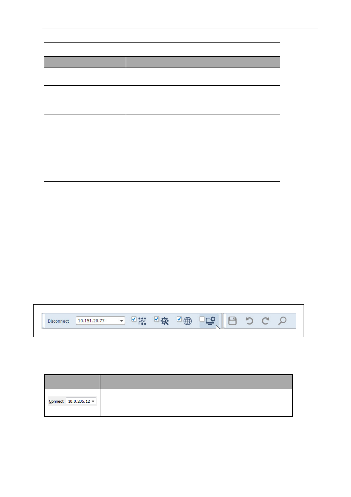
Chapter 5: Using MobilePlanner Software
Help Menu
Menu Option Description
Fleet Operations Workspace
Core User's Guide
Document Library (online) Provides link to:
What's This? Selecting this menu option, or using the shortcut Shift +
Open Output Log Folder Opens the folder containing saved MobilePlanner output
About MobilePlanner... Provides information on the current version of MobilePlan-
Allows you to open a Windows type help version of this
guide while using MobilePlanner software.
http://www.ia.omron.com/products/category/robotics/mobilerobots/index.html
F1, and then clicking on the MobilePlanner workspace displays a pop-up containing a brief description of some features.
logs.
ner and underlying applications/libraries.
5.5 The MobilePlanner Toolbars
There are three toolbars possible in the MobilePlanner interface:
l The main toolbar, which is located at the top of the MobilePlanner interface.
In Map mode only:
l The Map Controls toolbar is a floating toolbar, which you can move within the map
area.
l The AMR toolbar, below the map.
The following sections describe each set of tools.
Main Toolbar
The MobilePlanner main toolbar is located at the top of the window, under the main menu.
Figure 5-6. Example of the Main Toolbar, SetNetGo Selected
Table 5-3. Main Toolbar Icons and Their Functions
Toolbar Icon Description
Connects to the AMR or server at the specified IPaddress. Use the dropdown list to select a previously-used IPaddress, or type a new
IPaddress directly in the field.
63 Fleet Operations Workspace Core User's Manual 20569-020 Rev. D
Page 64

When an AMR or server is connected, this toggles to Disconnect.
Opens the Fleet window, which shows status and job statistics for all
AMRs in your fleet. It uses graphical icons to represent interrupted, canceled, in-progress, pending, and completed jobs. Click the checkbox to
have the Fleet window open when you connect to an AMR or Fleet Manager.
Displays the Configuration mode tab, which is used to set configuration
parameters. For details, see Configuring the AMR on page 140. Click the
checkbox to have the Config tab open when you connect to an AMR or
Fleet Manager.
Displays the Map mode tab, which is used to edit the map. For details,
see Editing a Map File on page 93. Click the checkbox to have the map
load when you connect to an AMR or Fleet Manager.
Displays the SetNetGo mode tab, which is used to access the SetNetGo
interface. For details, see Using the SetNetGo Software on page 114.
Click the checkbox to have SetNetGo open when you connect to an AMR
or Fleet Manager.
Saves changes to the active map or configuration file on the AMR.
Lets you undo the most recent action performed on the map or config
file.
Lets you restore the most recent item you undid in the map or config
file.
When MobilePlanner is in the Config mode, allows you to search all configurations for specific key words. Allows you to find parameters by
name, or search for a specific word in a parameter’s description (searching for ‘preferred’ in the example below). You can edit the Config values
in the main tab or in the search results window.
You can restrict the search to Non-Default parameters.
20569-020 Rev. D Fleet Operations Workspace Core User's Manual 64
Page 65

Chapter 5: Using MobilePlanner Software
Robot and Map Toolbars
Figure 5-7. Search Window - Searching for ‘Auto’
The map toolbars control the view of the map, set a goal at the AMR position, and localize the
AMR. (Localizing is telling the AMR where it is on the map of the work area.) There are two
different map toolbars available: one when the Show Robot button is toggled ON (the AMR is
displayed on the map); the other with the Show Robot button toggled OFF (the AMR is hidden
from the map).
Figure 5-8. Robot Toolbar (Show Robot ON)
65 Fleet Operations Workspace Core User's Manual 20569-020 Rev. D
Page 66

Figure 5-9. Floating Map Toolbar
Table 5-4. Robot and Map Toolbar Icons and Their Functions
Toolbar Icon Description
Some of the following icons are available when the Show Robot button is toggled ON, but
are disabled if the AMR cannot service the request because of low state of charge, or if E-Stop
is pressed.
Stops the AMR any time you click this icon, even when navigating in
autonomous mode.
NOTE: You can also use your keyboard’s Esc key to stop the
AMR.
Sends the AMR to a point you select on the map.
Sends the AMR to a goal you select on the map.
20569-020 Rev. D Fleet Operations Workspace Core User's Manual 66
Page 67
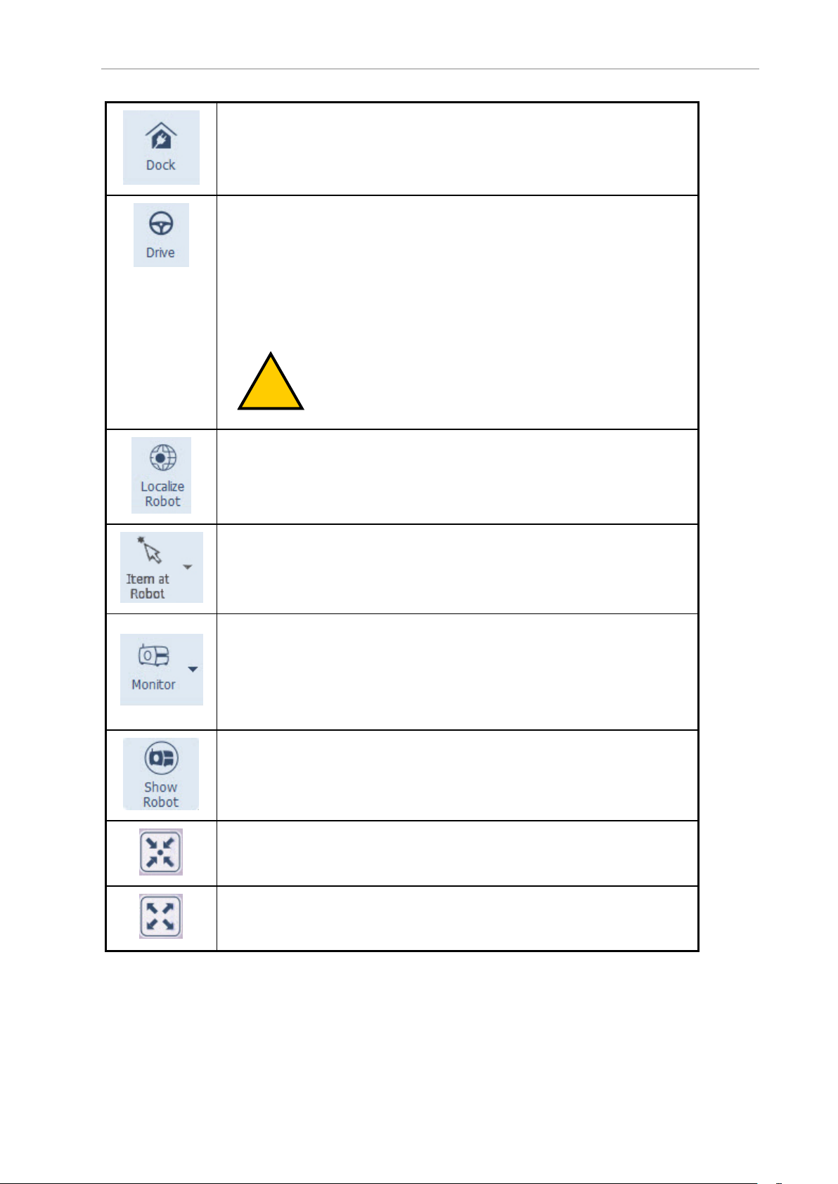
Chapter 5: Using MobilePlanner Software
!
ON when the AMR is on a dock or heading to a dock. Also sends the AMR to a
dock.
When OFF, releases the AMR from the dock.
Opens the Drive pad, which is used to move the AMR in its environment. Be
sure that you have Manual Override toggled OFF, which prevents the AMR
from running into anything while you are driving it. Even with Manual Override turned ON, the AMR will avoid any obstacles detected by its navigation
laser when traveling over 300 mm/s.
Highlight (click on) the pop-up window, and use the mouse or the arrow
keys on the keyboard to move the AMR in the direction you want it to go.
CAUTION: When Manual Override is ON, the background
of the map turns yellow, indicating "use caution" while driving.
Opens the Localize Robot dialog, which is used to localize the AMR to a point
selected on the map.
Allows you to create a goal and/or door with goals, place a cart, or place a
dock at the AMR’s current location.
The Monitor robot feature is available only when the Show Robot button is
toggled on. It provides a convenient place to monitor important AMR details
(battery info, state, job counts, sensors, and queuing stats), and the status
of digital inputs/outputs. It also provides a place for sending an AMR on a
route, adjusting audio input/output volumes, and inputting Say commands
(phrases that the AMR speaks with its text-to-speech converter).
Shows the location of the AMR on the map. Several toolbar features won't
function unless this is toggled ON. Others won't function unless it is toggled
OFF. The background color of the icon turns darker when it is ON.
Centers the map on the current AMR. This is helpful when you have multiple AMRs in your workspace and you need to locate a specific AMR quickly.
It also allows you to watch the AMR as it performs tasks.
Adjusts the map view to fit in the map window.
67 Fleet Operations Workspace Core User's Manual 20569-020 Rev. D
Page 68

Zooms map out (reduced magnification, more map visible).
Zooms map in (increased magnification, more details visible).
Allows you to pan around the map.
1.
Click on the Pan icon to display the Pan Map box.
2.
Click on any of the four arrows of the PanMap box to move that direction in the map.
The keyboard arrow keys perform the same function as clicking on
the Pan Map arrows.
NOTE: If Center on Robot is turned on, you cannot pan the
map window.
NOTE: You can also pan the map by clicking and holding the
right mouse button while moving the mouse around the
workspace.
The Pan Up, Pan Down, Pan Left and Pan Right icons are available when the
Pan button is turned on.
5.6 Using Monitor
The Monitor feature provides a convenient place to monitor important AMR and Fleet Manager details (battery info, state, job counts, sensors, and queuing stats), and the status of digital
inputs/outputs.
It also provides a place for sending an AMR on a route, adjusting audio input/output
volumes, and inputting Say commands (phrases that the AMR speaks with its text-to-speech
converter).
Monitor can be activated either in single AMR or Fleet mode, when you are attached to a Fleet
Manager.
The displayed data and appearance will differ, depending on whether you are connected to a
Fleet Manager or an AMR, and whether or not the Show Robot button is ON.
To Access Monitor
1.
Click Monitor on the Robot toolbar to display a sub-menu with various AMR attributes
you can monitor.
20569-020 Rev. D Fleet Operations Workspace Core User's Manual 68
Page 69

Chapter 5: Using MobilePlanner Software
Figure 5-10. Monitor Drop-down Menu
The following table describes the various attributes you can monitor.
Item Description
Dashboard Displays an information window listing jobs (number of interrupted,
canceled, in-progress, pending, and completed) and AMRs (that
need assistance, have E-Stop pressed, busy, available, and unavailable).
Fleet Details Lists information about AMRs in the fleet - availability, status of
assigned jobs, queuing and state information, system status, and
memory use.
Details Lists specific details about the currently monitored AMR - bat-
tery/charge stats, path planning and following, AMR pose information, queuing statistics, system data, and wireless data.
Digital I/O Allows you to monitor custom input/output states, and toggle out-
put states ON (green) or OFF (black).
Audio Controls incoming and outgoing audio volume.
Audio Incoming: MobilePlanner Out: controls the level out (for
example, 'sendSpeech').
Audio (Output): Robot Out controls the volume of speech audio files
the AMR plays.
Tasks Lists current tasks assigned to monitored AMR, and allows you to
add them to the selected route builder list (normally a goal versus a
route).
Macros Lists and allows immediate execution of all existing macros.
69 Fleet Operations Workspace Core User's Manual 20569-020 Rev. D
Page 70

Item Description
Routes Lists and allows immediate execution of all existing routes.
Adjusting Audio Levels
The robot monitor also allows you to adjust the incoming and outgoing audio levels. These
controls are shown in the following figure.
Figure 5-11. Audio Controls
You can adjust audio output level by moving the slide controls to the right (louder) or left
(quieter). You can amplify the effect of the incoming audio control setting by selecting the 2X
check box.
Making the Robot Talk
The Monitor > Audio window includes a text-to-speech feature. You can use the "Say" field to
input a word or phrase that you want the AMR to speak.
When you click the Say icon, the text is converted to synthesized speech through the text-tospeech converter.
5.7 The MobilePlanner Map Window
The MobilePlanner Map window displays the map file that you are editing. When you first
start MobilePlanner, no map is displayed until you connect to an AMR or Fleet Manager. You
can also open a map saved locally on your computer or network. For details on opening maps,
see Loading an Existing Map File on page 91.
Below is an example of the MobilePlanner interface with a map file opened. Note that the
Show Robot button is toggled OFF, which exposes the tools on the Draw function tab.
20569-020 Rev. D Fleet Operations Workspace Core User's Manual 70
Page 71

Chapter 5: Using MobilePlanner Software
Figure 5-12. The MobilePlanner Interface, Map Tab, Show Robot OFF
NOTE: To create the initial map, you must first use MobilePlanner to scan the
AMR's environment and then turn the scan into a map. For details, see Scanning
the Operating Area on page 88.
Map Zoom
Maps initially open zoomed out to give you an overall view of the AMR’s environment. To
quickly find the current AMR in the map, click the Show Robot button, then click Center on
Robot. The map zooms in, focused on the AMR.
NOTE: The Show Robot button must be ON to display the Center on Robot
icon.
71 Fleet Operations Workspace Core User's Manual 20569-020 Rev. D
Page 72

Map Controls
You can use the mouse or the keyboard to adjust the map view. The following table describes
the map controls.
To... Do this...
Pan Mouse: press and hold the right mouse button (or use the scroll wheel),
move the mouse around the workspace.
Keyboard: use the arrow keys to move right, left, up and down.
NOTE: You can’t pan the map when the Center on Robot tool-
bar icon is toggled ON.
Zoom in Mouse: press the Shift key and click the right mouse button; or you can
rotate the scroll wheel forward (without the Shift key).
Keyboard: press the Shift key and the Up arrow.
Zoom
out
Mouse: press the Shift key and click the left mouse button; or you can rotate
the scroll wheel backward (without the Shift key).
Keyboard: press the Shift key and the Down arrow.
Map Features
Map features can be as simple as the static features of the environment (walls, doors, etc.) or,
depending on the features you add to the map, they can be quite intricate. In general, more
map detail improves AMR navigation.
To create a detailed map of the environment, you need to scan the environment thoroughly
and then edit the map. This is done in the MobilePlanner software. For more information on
environment scanning and map editing, refer to Scanning the Operating Area and Editing a
Map File on page 93.
The following table describes the different features shown on the map.
Map Feature Definition
This represents the LD-60 and LD-90 AMRs. Notice
that the white arrowhead indicates the direction that
the AMR is currently facing.
This represents the Cart Transporter. Notice that the
white arrowhead indicates the direction that the AMR
is currently facing.
This represents the LD-250 AMR. Notice that the
white arrowhead indicates the direction that the AMR
is currently facing.
20569-020 Rev. D Fleet Operations Workspace Core User's Manual 72
Page 73

Chapter 5: Using MobilePlanner Software
Map Feature Definition
This represents the HD-1500 AMR. Notice that the
white arrowhead indicates the direction that the AMR
is currently facing.
This is the Legacy representation of a robot. Notice
that the black line indicates the direction that the
AMRis currently facing. This may still apear in some
system maps.
The black dots and lines on the map are the walls,
doors, and other static fixtures in the environment.
The blue dots and lines are the features the AMR
"sees" with its navigation laser. Some AMRs have
additional lasers which produce different colored dots.
The yellow squares represent the location where the
AMR should go, and the black line is the direction it
should face, when it starts to dock. The dock object
should be approximately 1 to 1.5 meters in front of
the dock.
The green squares represent a goal. The line indicates
the AMR’s desired heading when it reaches the goal.
Goals are predefined locations where you can send
the AMR.
The light turquoise squares represent Standby Goals.
These can be either buffering or parking.
Map Modes
When Show Robot is on, there are several map modes which provide a different AMR func-
tion (see the following table):
73 Fleet Operations Workspace Core User's Manual 20569-020 Rev. D
Page 74

Icon Map Mode Definition
Send Robot Allows you to send the AMR to a certain spot on the map.
When active, clicking on the map causes the AMR to move
to that spot.
To activate this mode, click Send Robot on the Toolbar,
then click on the map with the left mouse button to send
the AMR to that point. You can also send the AMR by holding down the Ctrl key and clicking on the map.
To specify the AMR’s desired heading when it arrives at the
designated spot, press the mouse button and drag.
To deactivate this mode, click the Send Robot icon to
toggle it off.
After you click a point on the map, the AMR (the red oval)
autonomously drives to the point you selected.
Robot Control Allows you to drive or send the AMR using the keyboard. To
activate this mode, hold down the Ctrl key and press the
arrow keys.
Localize to Point Allows you to localize (mark the AMR’s location) the AMR
on the map. See AMR Localization on page 228 for details.
NOTE: When Show Robot is OFF, the cursor shape indicates what your mouse
click or movement will do (see the following table). These cursors are visible
after selecting an object.
Cursor Function Appears when
you...
Open the Edit window (double-click), or drag the object
within the map.
Change the heading of a goal or dock, or resize a line. Click on the goal/-
Resize a rectangular object (the cursor is rotated 90°
depending on which corner you pick).
Rotate the object. Click on the heading
Double-click or
click-and-hold on an
object, other than
on a heading
marker or endpoint.
dock heading
marker or either
end of a line.
Click on a corner of
an area or sector.
arrowhead of an
area.
20569-020 Rev. D Fleet Operations Workspace Core User's Manual 74
Page 75

Chapter 5: Using MobilePlanner Software
Map Legend
As you edit the map file, you can create goals, lines, forbidden areas, docks and many other
features in the environment. Use the Map Legend to keep track of all of the different features
that can be added to your map file.
Select Map >Legend... from the main menu to open the Map Legend window.
Figure 5-13. Map Legend (Partial)
5.8 MobilePlanner Status and Tray Displays
The status and tray displays allow you to monitor the status of the AMR (or AMRs) directly
from the software interface.
Status Information
The status of the selected (red) AMR is displayed directly beneath the map, as shown in the following figure.
NOTE: In MobilePlanner, the Status area is only visible when the Show Robot
button is toggled ON.
75 Fleet Operations Workspace Core User's Manual 20569-020 Rev. D
Page 76

Figure 5-14. Status Information
The following table describes some of the available status information.
NOTE: By default, the status area shows only a small sub-set of available AMR
details. To view other data, see Displaying Other AMR-Specific Details (below).
Status Detail Description
RobotX and RobotY The current X and Y position of the AMR in its operating space.
RobotTh Robot theta - the AMR’s heading (which way it’s facing), in °, meas-
ured counter-clockwise. 0 is the x axis.
TransVel The velocity of the AMR.
RotVel The AMR's rotational velocity (how fast it is turning).
Displaying Other AMR-Specific Details
There are many other AMR-specific parameters you can choose to display in the status area.
To view and/or add other AMR details, in the MobilePlanner main menu, select Robot > Mon-
itor > Details.
20569-020 Rev. D Fleet Operations Workspace Core User's Manual 76
Page 77
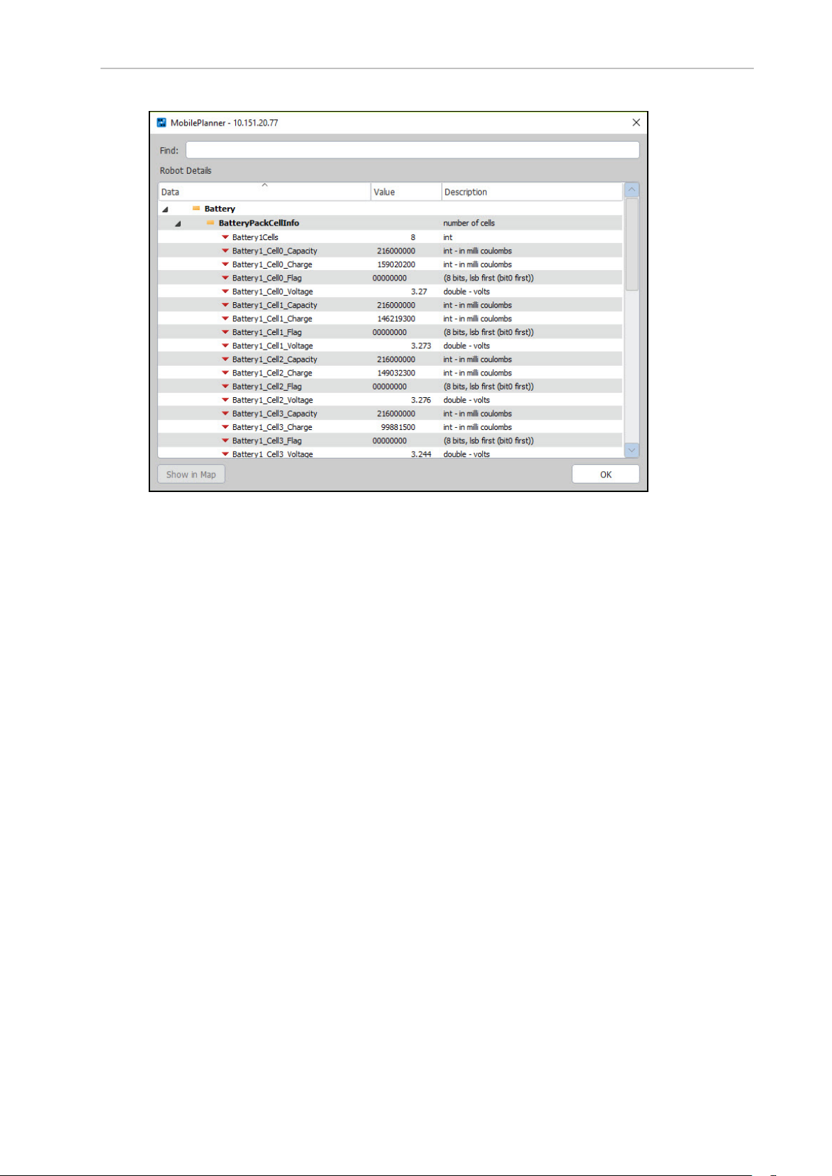
Chapter 5: Using MobilePlanner Software
Figure 5-15. Robot Details Window
If you want to add a detail to the status area, click on the detail, then click the Show in Map
button (lower left corner). Or, you can right-click in the status area to Hide in Map.
77 Fleet Operations Workspace Core User's Manual 20569-020 Rev. D
Page 78

Tray Information
Below the status area, there is a tray that contains information such as connection status and
the pointer location.
NOTE: The tray information is always visible.
Figure 5-16. Tray Information
The following table describes the items available in the tray.
Tray Icons Description
Displays the temperature reading of the current AMR.
Indicates the state of charge (in %). The icon turns yellow when the
charge begins to run low. It flashes red when the battery is low and the
AMR needs to dock.
X: Shows the X position of the pointer.
Y: Shows the Y position of the pointer.
20569-020 Rev. D Fleet Operations Workspace Core User's Manual 78
Page 79

Page 80

Chapter 6: AMR Driving Overview
!
Now that you have installed the MobilePlanner and set up a wireless connection to your
AMR, you are just about ready to drive the AMR around your workspace. You can drive the
AMR using either the pendant and walking around your environment, or operating it from the
MobilePlanner software. Using the mouse and keyboard, you can dock and undock the AMR
from its docking station, drive the AMR forward, backward, turn the AMR, and control its
speed.
CAUTION: Before attempting to drive the AMR, be sure to read the appropriate AMR user's guide and Mobile Robot Safety Guide so you are familiar
with the AMR's operation.
6.1 Before Driving the AMR
Whether you are driving the AMR with the pendant or from MobilePlanner, be sure the AMR
is not docked.
6.2 Manual Override
Autonomous Drive mode is the AMR’s default driving mode, and ensures the AMR does not
run into anything in its environment. When driving the AMR using MobilePlanner, Autonomous Drive mode prevents the AMR from entering forbidden or restricted spaces. If driving the
AMR using the pendant, you can have the AMR enter forbidden or restricted spaces, but the
AMR always obeys the lasers for obstacle avoidance.
When Manual Override is ON, the map background turns yellow (see below).
20569-020 Rev. D Fleet Operations Workspace Core User's Manual 80
Page 81

Chapter 6: AMR Driving Overview
Figure 6-1. MobilePlanner, Manual Override ON
To drive with Autonomous Drive mode OFF:
1.
In the MobilePlanner main menu, click Robot > Robot Tools > Manual Override.
2.
Click Yes to acknowledge the Manual Override dialog prompt.
NOTE: If you turn Autonomous Drive mode back ON when the AMR is in a
restricted or forbidden area, it will not be able to drive itself out of the restricted
area, and will require you driving it out using the pendant (which always
ignores location-dependent areas). Also, while an AMR is in a forbidden area,
even with Autonomous Drive mode still OFF, pressing the Send Robot button
will not cause the AMR to drive out of the forbidden area. You must drive the
AMR out of a forbidden area using the pendant or your PC’s arrow keys. See
Driving Using the Software Interface (Drive Pad or keyboard) on page 83.
6.3 Driving Using the Pendant
This section provides information on the pendant. Also see your AMR’s user guide.
Preparation
1.
If not already done, power up the AMR (press and release the AMR’s ON button). The
full power-up sequence can take several minutes.
2.
Wait for MobilePlanner and/or the AMR to indicate it is ready (via wheel lights, LCD or
touch screen).
3.
Plug the pendant into the AMR’s pendantconnection port.
For LD-series AMRs, this port is under an access panel on the left rear side of the AMR,
as shown in the following figure:
Figure 6-2. Connecting the Pendant to an LD-60
For the HD-1500 AMR, the pendant port is on the right side of the Operator panel, on
the rear end of the AMR.
81 Fleet Operations Workspace Core User's Manual 20569-020 Rev. D
Page 82

!
CAUTION: Driving the AMR with a pendant overrides the hardware
E
N
ABLED
P
OWER
A
B
C
D
E
safety features (E-stop, sonar). Use caution when driving the AMR with
a pendant.
Figure 6-3. Pendant Controls
20569-020 Rev. D Fleet Operations Workspace Core User's Manual 82
Page 83

Chapter 6: AMR Driving Overview
Callout Description Callout Description
A Speed Control D PowerEnabled LED
B Goal Button E 3-Position Enable Switch
C Directional Control
l
The green LED indicates that the pendant is plugged into a live connection.
l
Squeeze and hold the trigger in, then:
o
Push the directional control forward or back to drive the AMR forward or back.
o
Push the directional control to the left or right to turn the AMR to the left or right.
l
The AMR slows to a stop when you release the trigger. To stop more quickly, continue
to hold the trigger down and pull or push the directional control to its limit in the
opposite direction of the AMR’s travel.
l
Speed is related to the positions of the directional control and the SPEED control.
l
The pendant’s GOAL button is primarily for marking positions while making a map
scan, but can be configured to perform other actions while not making a map scan.
NOTE: If driving with the pendant, proceed to Scanning the Operating Area on
page 88.
6.4 Driving Using the Software Interface (Drive Pad or keyboard)
NOTE: The Drive Pad functionality is not available for the HD-1500 AMR. The
Drive Pad display will be greyed-out. Its operation is not changed for the LD
AMRs.
Using MobilePlanner software and your PC's mouse and keyboard, you can:
l Dock and undock the AMR from a docking station
l Drive the AMR forwards, backwards, and turn
l Control the AMR's speed
To drive the AMR using the software:
1.
Ensure Show Robot is active, then click Center on Robot to locate the AMR (shown as
a red oval icon) in the map window (shown in the following figure).
83 Fleet Operations Workspace Core User's Manual 20569-020 Rev. D
Page 84
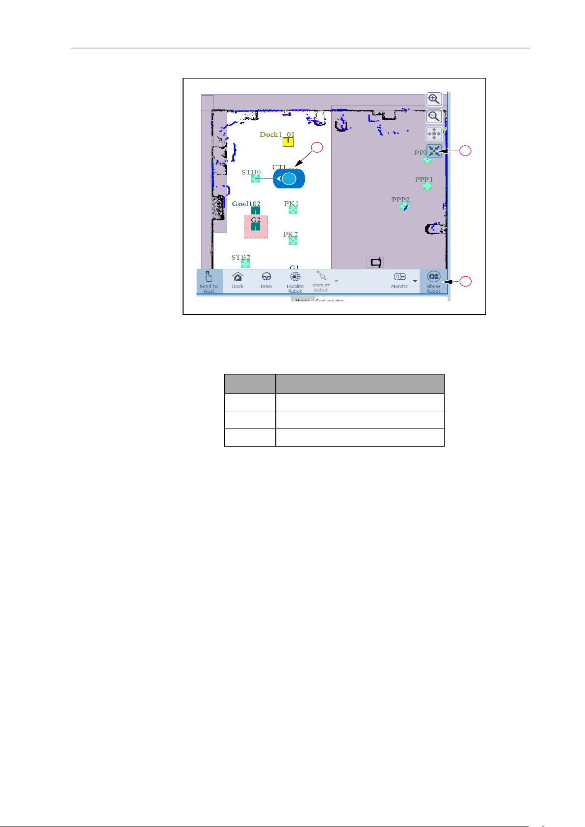
1
2
3
Figure 6-4. AMR on Map (Show Robot Active)
Table 6-1. AMR on Map Description
Item Description
1 Show Robot
2 Center on Robot
3 Robot (LDAMR shown)
2.
Select Robot >Undock from the main menu, or click Dock (on the AMR tool bar) to
turn docking off. In the map window, you should see the AMR move away from the
docking station.
3.
If the background in MobilePlanner is yellow (the AMR is not in Autonomous Drive
mode), un-check Robot > Robot Tools > Manual Override from the MobilePlanner
main menu.
4.
Click Drive to display the MobilePlanner Drive pad with Speed slider (figure below).
20569-020 Rev. D Fleet Operations Workspace Core User's Manual 84
Page 85

Chapter 6: AMR Driving Overview
Figure 6-5. Drive Pad with Speed Slider
5.
Highlight (click on) the map window, and use the mouse to click on the drive pad buttons, or use keyboard’s arrow keys to control the AMR’s direction. Use the speed slider
(at the bottom of the Drive pad) to control the AMR’s speed.
NOTE: If the speed slider is all the way to the left (-), the speed is set to
zero and the AMR will not move.
85 Fleet Operations Workspace Core User's Manual 20569-020 Rev. D
Page 86

Chapter 7: Scans and Maps
7.1 Map Overview
With Fleet Operations Workspace Core software, AMRs know where they are and drive from
one place to another by themselves, without a human operator. To do this, the AMR must
have a prepared map of the static features in its operating environment. MobilePlanner software makes creating maps for one, or an entire fleet of AMRs fast and easy.
Maps are one of the most important features of MobilePlanner. In MobilePlanner, a map is a
scanned representation of the floor plan in the AMR's operating space. Maps contain the static
features in the AMR's environment, such as walls, doors, permanent shelving, etc. They also
contain user-definable sectors, lines, and areas that help the AMR perform its job.
7.2 Scan Overview
The next step is to create a map of the AMR’s environment. In general, the process is as follows:
l
Read the section on scanning (see Scanning Overview on page 86), and the section on
scanning tips.
l
Read the section on driving the AMR (see AMR Driving Overview on page 80).
l
Scan the AMR’s operating space (see Scanning the Operating Area on page 88).
l
Use MobilePlanner to generate a map from the scan.
7.3 Scanning Overview
Before the AMR can perform autonomous tasks, it needs to have an accurate map of its environment. It is best to create a scan that includes as many stationary features as possible in the
workspace. After scanning, use MobilePlanner to turn the scan into a map, then begin assigning tasks to your AMR.
How Does the AMR Scan its Environment?
The AMR uses its forward laser, which scans in a 240° arc for the LD-series AMRs. The HD1500 AMR usesonly its front laser, scanning in a 270° arc. Note that the HD front (and rear)
laser is not centered on the AMR.
What Gets Scanned?
Scans are on a thin horizontal plane. The scan is taken about 7.9 inches (200 mm) for the LDseries and 6.9 inches (175 mm) for the HD-1500 off the floor. So tables appear as four legs; a
pedestal appears as a single pole, minus the feet.
Distance From Walls
The AMR’s sensing range is 30 meters (about 98 feet). While scanning, keep walls within that
range as you drive throughout the workspace. For instance in a large warehouse, run the AMR
20569-020 Rev. D Fleet Operations Workspace Core User's Manual 86
Page 87

Chapter 7: Scans and Maps
along the outer walls as well as through the middle of the space.
Uni-directional Versus Bi-directional Scanning
Uni-directional scanning (or scanning in a single direction) works very well for hallways and
small rooms. Bi-directional scanning (or scanning in two directions) will ensure complete scanning of all features (such as vending machines or bookshelves).
Doors and Windows
When scanning environments with doors, ensure the doors are open in places where the AMR
will drive. Some glass surfaces, particularly those with dark backgrounds, reflect the range
finder signals; others don’t or reflect weakly. Consider retrofitting particularly troublesome
places with tape or other treatments to obtain proper scans. Additionally, you can designate
these features as obstacles in the map using a forbidden zone sector.
Dynamic Features
During scanning, MobilePlanner sees people walking by, swinging doors and other things
moving throughout the workspace. If a group forms during scanning, have them follow
behind (not stand in front of) the AMR’s scanner so they do not become permanent features of
your map. For an HD-1500, have them stand behind and to the left, since the laser being used
for scanning is on the front-right of the AMR. When editing the map, erase dynamic features
(like the group) to improve the map’s quality.
Docks
When scanning, scan and press the goal button to mark the AMR's dockso it can recharge
when its battery runs low.
Scanning Tips
The following general tips will help increase the AMR’s scanning accuracy, and reduce possible map errors:
l Remove any features like chairs, rolling cabinets, etc. that might not be present during
normal operations.
l Walk behind the AMR while scanning (and ensure others walking with the AMR also
walk behind the laser’s sensing area). With an HD-1500, walk behind and to the left of
the AMR, so that the laser (on the front right) doesn't see you.
l Drive the AMR into tight corners, down small corridors, and between stationary objects
(with enough room).
l Scan in multiple directions - scan clockwise for one scan, counter-clockwise for another.
l If scanning rough terrain (like diamond plate flooring), drive slowly (to reduce the
chances of wheel slip) and in multiple directions. This will help minimize introducing
errors into the scan.
l Open doors that might be open during normal operations, and doors the AMR will
have to drive through.
l
Drive the AMR through previously scanned areas.
87 Fleet Operations Workspace Core User's Manual 20569-020 Rev. D
Page 88

NOTE: Driving the AMR back through previously scanned areas, and
returning to its starting position can help minimize errors.
Scanning the Operating Area
Be sure to drive the AMR to all of the places you would expect it to go on its own. Drive all
the way around a room, not just in and out of the doorway. Turn the AMR to point into
corners and move around stationary features. In other words, be thorough!
Also, while driving the AMR, orient and stop it along the way to mark important goals (especially a dock object). Later, you can edit these and add additional goals within MobilePlanner
software.
1.
If not already done, launch MobilePlanner and connect to the AMR.
NOTE: Before starting these steps, make sure the AMR is not charging. If
the AMR is docked, undock it by clicking Robot > Dock (in the
MobilePlanner main menu bar), or by clicking the Dock button in the
MobilePlanner toolbar (only visible if Show Robot is active).
2.
From the MobilePlanner main menu, select: Robot >Map Creation >Start Scan.
3.
Enter a name for your scan file in the New Scan Name field and click OK.
This initiates the scanning process. Notice that the AMR's LCDchanges to map scanning mode.
NOTE: Before driving the AMR, make sure it is in Autonomous Drive
mode (a yellow background in MobilePlanner indicates the AMR is not in
Autonomous Drive mode). To enable Autonomous Drive mode, un-check
Robot > Robot Tools > Manual Override in the MobilePlanner main
menu bar.
4.
Use the pendant and drive the AMR around its operating space.
NOTE: Be sure to drive the AMR around the entire operating area to create an accurate scan of your environment.
5. If you want to create a goal at the point where the AMR is stopped, press the pendant’s
black GOALbutton to mark a goal.
6.
Continue driving the AMR around until you have a thorough scan of your environment.
7.
Return the AMR to its starting position.
8.
After you have finished the scan, select Robot >Map Creation >Stop Scan from the
MobilePlanner menu.
The resulting scan file resides on your AMR, but not on the PC running MobilePlanner. The
file name is the name you entered for the scan with the ‘.2d’ extension. If scanning using Acuity, the file name has a ".z2d" extension, and includes additional data such as camera images
used to scan overhead lights.
NOTE: Acuity Localization is not yet supported for the HD-1500 AMR.
20569-020 Rev. D Fleet Operations Workspace Core User's Manual 88
Page 89

Chapter 7: Scans and Maps
Convert the Scan into a Map
After the AMR scans the operating environment, you need to turn the scan file into a map file.
To do this, open the scan file (.2d) in MobilePlanner.
NOTE: MobilePlanner can process only one scan file at a time. Opening a
second scan file disables the toolbar Start button until the first scan is finished.
1. Open the MobilePlanner software.
2.
Select File >Open on Robot, then select the AMR, either from a list or by IP address.
The Open File on Robot dialog box appears.
Figure 7-1. Open File on Robot Dialog
3.
Check the Scan File: checkbox, select the scan file you just created from the pulldown
list, and click Open.
A new map window and the Scan Tools toolbar appear, and the conversion (registration) process begins automatically. Initially, the map shows an AMR icon in the map
window. During file processing, the software adds scan points to the map window and
updates the AMR's position showing a blue trail to trace the AMR's previous positions.
NOTE: Be patient! Converting a large scan file can take considerable time
(and memory), and is based on the size and layout of the area being
scanned (for example, a small facility could take 20 seconds, a 20,000
square foot facility could take over an hour). If the small AMR icon in the
lower right corner of the map window is still moving, the conversion process is still underway.
NOTE: PC memory (RAM) is critical when processing a very large scan
file. Processing large scan files with insufficient RAM can significantly
degrade the performance of all applications. If this occurs, it might be
necessary to create smaller scan files and use the Map Insert feature to
assemble the pieces (refer to Inserting a Map File into an Existing Map
File on page 104 for details).
When processing is complete, the AMR icon and its trail disappear from the map window, and the scan icon in the status bar stops animating. If the map has too many stray
89 Fleet Operations Workspace Core User's Manual 20569-020 Rev. D
Page 90

objects or otherwise does not appear as you need, you can adjust the scan settings and
re-process the scan file (for details, refer to Changing the Scan Settings on page 109).
4. Save the cleaned map file locally on your PC.
5.
In the Scan Tools toolbar, click Finish to complete the conversion process.
NOTE: Unless working in batch mode, you must finish converting one
scan before opening and converting another scan.
6. Edit the map file to erase (Draw pane > Eraser) stray, non-stationary objects (like chairs,
people, etc.). Add forbidden areas and sectors. Create goals and macros, and assign
tasks to your AMR. Refer to Editing a Map File on page 93.
7.
Select File > Save on Robot to save the finished map file on the AMR, then select your
AMR from the MobilePlanner menu. Optionally, you can enter a Fleet Manager address
so it can be shared between multiple AMRs.
NOTE: Select Yes when prompted to make the new map the AMR’s current map so the AMR can localize, and appear on the map (when you
click Show Robot).
Map Data
The finished map consists of points and lines (vectors derived from points) representing the
walls and other real features detected by the scanning laser.
Figure 7-2. Scanned Environment
7.4 Working with Map Files
This section explains map files and how to work with them in the MobilePlanner software.
20569-020 Rev. D Fleet Operations Workspace Core User's Manual 90
Page 91

Chapter 7: Scans and Maps
Making a Map
Before MobilePlanner can create a map of the mobile robot’s operating space, you have to
drive the robot through the operating space as it scans the area with its laser and (if installed)
Acuity. The resulting scan file contains all the raw data for features in the space. To be usable
for mobile robot navigation, you have to have MobilePlanner convert the scan file into a map
file.
Generally, you only need to make a map when deploying your AMR for the first time in a new
environment. Occasionally you might need to rescan if the workspace undergoes extensive
structural modifications or lighting changes, cubicles added in what was open space, a new
wing to the building, or remodel of an area. For more extensive map updates, MobilePlanner
provides the tools to integrate a new map, partially or wholly, into your original application
(refer to Inserting a Map File into an Existing Map File on page 104 for details).
The best time to create a map scan is when the environment is least busy, when you can minimize the amount of time spent avoiding people and other non-stationary obstacles, and when
you can move about, opening and closing doors, without disrupting normal daily activities.
What Information is Stored in a Map File?
Map files contain four kinds of data about an operating environment that the AMR uses in
planning navigation and executing tasks:
l Obstacles and features scanned by a laser, and/or overhead lights acquired by Acuity.
l Objects, such as goals, forbidden lines, and sectors that control AMR behavior.
l Macros and tasks associated with goals.
l Data that defines properties of special goal types and available tasks.
A map file name has an extension of .map. Scan file names have an extension of .2d.
Scan files for light localization have an extension of .z2d (scan file is a zip file referred to as
the Scan Package) or .zmp (map file from scan - a zip file referred to as the Map Package).
l For information on creating a map using the scanning laser, refer to Scanning the Oper-
ating Area on page 88.
l For information on creating a map using Acuity for light localization, refer to Creating
the Light Map on page 235.
Loading an Existing Map File
There is no map to display when you first start up the MobilePlanner software. You must use
MobilePlanner, with ‘Map’ checked, and connect to an AMR or Fleet Manager to open a map
file to edit. Or, you can open a map saved locally on your computer or (when the Map button
is checked) open a map that is currently in use on a specific AMR. You can also open maps
on the AMR that are currently not in use.
Opening a Map saved on your PC
When you use the Map button to open and edit your map files, you can save them locally on
your computer until you are ready to upload them to the AMR. Local map information is also
written in the debug info files.
Selecting File >Open from the MobilePlanner main menu displays a dialog that lets you
search for and select a local map file to open.
91 Fleet Operations Workspace Core User's Manual 20569-020 Rev. D
Page 92

Opening a Map stored on an AMR
You can also click the Map button to edit a map file that is already in use on an AMR, which
is helpful for making quick changes to the map or the AMR's route.
1.
In the MobilePlanner main menu, select File > Open on Robot to display a submenu
that lets you select a particular AMR.
2.
Either choose from the displayed AMR IPaddresses, or enter a new AMR IPaddress to
open a map on the specified AMR.
A dialog box appears in which you can choose between Configuration, Map, Scan, and
SetNetGo files.
Figure 7-3. Open File on Robot dialog
3.
Check Map File to choose a map file located on the AMR.
You can use the Map File list and/or click the Advanced button to search for and select
a map file to open, as shown in the following figure:
20569-020 Rev. D Fleet Operations Workspace Core User's Manual 92
Page 93

Chapter 7: Scans and Maps
Figure 7-4. Open File on Robot, Advanced dialog
4.
Select the map file you want to edit.
5.
Click Open to load the map file into MobilePlanner.
Editing a Map File
After you create the initial map of your environment, you can use MobilePlanner to edit the
map. First, use the Eraser tool (Draw pane) to remove map features that are temporary or
moveable fixtures, such as chairs or forklifts.
Using the Drawing Tools
When editing your map file, you use the drawing tools to select and erase objects in the map,
add goals, docks, forbidden lines and areas, as well as advanced lines and areas. The drawing
tools are shown below.
NOTE: These drawing tools are inactive (grayed-out) if Show Robot is active.
The Cut icon is inactive until you select something.
93 Fleet Operations Workspace Core User's Manual 20569-020 Rev. D
Page 94

Figure 7-5. MobilePlanner Draw Tab
Selecting and Erasing Objects in the Map
Use the Select button to select and highlight objects on the map. Press and hold the left mouse
button to move the object around the map window. Click the right mouse button to display a
pop-up menu that allows you to edit, duplicate, align, copy and cut the object.
NOTE: If there are overlapping objects on the screen, you can right-click on the
overlapping map objects. A sub-menu lists all objects under the cursor so you
can select the desired object.
Use the Eraser button to remove data points and lines from the map. Press and hold the left
mouse button to move the eraser over the data points or lines you want to remove. You can
adjust the size of the eraser by selecting the pull-down menu from the Eraser button. Choose
an eraser size from 5 to 1000 mm.
Cutting a Selection
Use the Cut icon (or Delete key) to remove any objects you have selected from the map.
Snapping Objects in Place
Use the Snap button to force rotate objects (goals, docks, lines, and areas) at multiples of 45°
angles. Deselect this button to draw or rotate at any angle.
Draw Tab
You can use the Draw tab to add and edit map items (for details on map editing, refer to Working with Map Files on page 90).
20569-020 Rev. D Fleet Operations Workspace Core User's Manual 94
Page 95

Chapter 7: Scans and Maps
NOTE: The Draw tab is only active when the Show Robot button is toggled
OFF.
The following table lists the toolbar icons and their functions.
Item Description
Select a feature (point, line, area, etc.) on the current map.
The status bar on the bottom left side of the window displays
information about the feature you selected, such as:
Remove points or lines from the active map. Does not remove
custom/landmark objects.
1. Click on the Eraser icon.
2. Use the pull down menu to select the eraser size from
5mm to 10000mm.
3. Click and hold the left mouse button, while moving the
mouse over the points and lines you want to erase.
Click Goal, then click on a map location to add a goal. In the
Edit Goal dialog box you can:
l label the goal
l provide a description
l select the type of goal (if available)
l adjust the X/Y position and heading. You can adjust the
heading after placement by holding the left mouse button down, and dragging around the goal. The heading
will follow the cursor.
Click Docks, then click in the map at the new dock’s location.
In the Edit Dock dialog box you can:
l label the dock
l provide a description
l select the type of dock
l adjust the X/Y position and heading. You can adjust the
heading after placement by holding the left mouse button down, and dragging around the dock. The heading
will follow the cursor.
95 Fleet Operations Workspace Core User's Manual 20569-020 Rev. D
Page 96
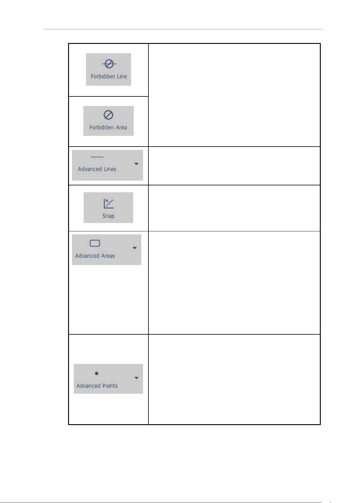
AMRs will not cross forbidden lines, or enter forbidden areas. To
add a forbidden line or area:
1. Press and hold the left mouse button.
2. Drag the mouse to create the line or area and to adjust
the size.
3. Release the mouse button (the line or area remains
selected).
4. Press and hold the left mouse button.
5. Drag the selected line/area to move its location on the
map.
6. For an area, click and hold on the heading arrowhead,
then drag to rotate the area.
Allows you to measure distances, display a measuring stick,
add Preferred or Resisted Lines, or a Map Data Line to your
map.
Place lines and rectangles to the x/y axis (or 45° angles).
Deselect this button to draw or rotate at any angle.
To temporarily toggle this button while drawing a line or rotating a rectangle, press and hold the Ctrl key. Release the Ctrl
key after making the edit.
Places special areas on the map that the AMRs will avoid entering or crossing (e.g., door swing sectors, need to enter sectors,
resisted sectors, etc. To add an advanced area to the map:
1. Press and hold the left mouse button.
2. Drag the mouse to create and size the line or area.
3. Release the mouse button (the line or area remains
selected).
4. Press and hold the left mouse button.
5. Drag the selected line/area to move its location on the
map.
6. For an area, click and hold on the heading arrowhead,
then drag to rotate the area.
Opens a submenu for adding a label to any advanced feature
on the map.
1. Click on Advanced Points, then select Label from the
submenu.
2.
Click on a feature in the map you want to label, then
use the Edit Label dialog box to enter a label, provide a
description, and adjust the X/Y position and heading.
NOTE: The label box is a special text box
that does not scale when zoomed.
20569-020 Rev. D Fleet Operations Workspace Core User's Manual 96
Page 97
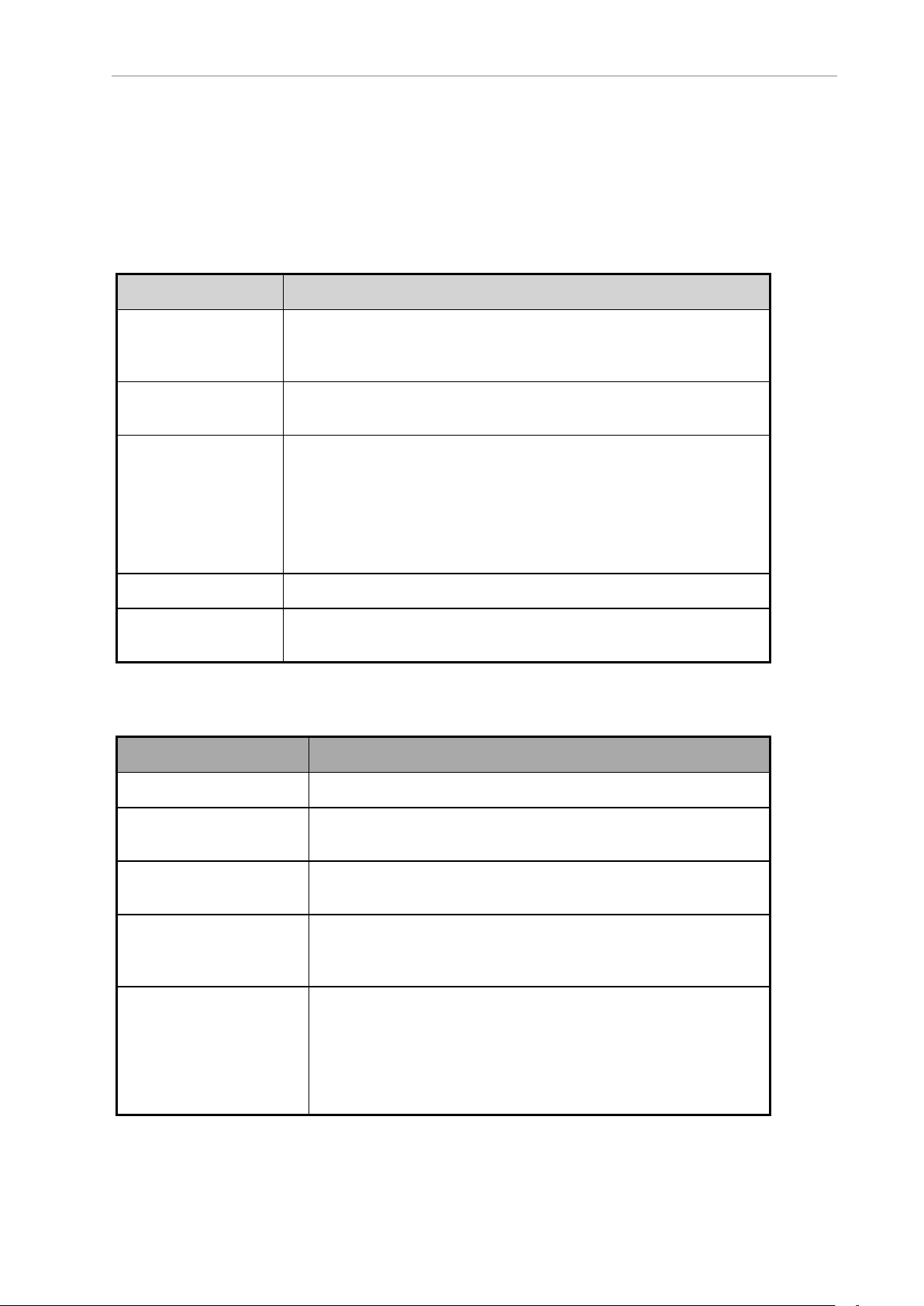
Chapter 7: Scans and Maps
Using Advanced Lines and Areas
Advanced lines and areas (in Config > Robot Operation > Map Features) control the AMR's
behavior. You can alter traffic flow, restrict the AMR from entering an area, and have the AMR
use a preferred route. For more information on creating these features and more, refer to Traffic
Management on page 202.
Advanced Lines
Advanced Line Definition
Measuring Stick Places a line on the map to measure distances in the map. You can
change the measurement units by selecting View >Units from the
main menu.
Preferred Line Places a line on the map representing the path that you prefer the
AMR use.
Resisted Boundary Places a boundary line that the AMR resists crossing. If there is no
other way around an obstacle, the AMR will cross a resisted boundary
(though at a higher cost). For more information, refer to Cost-Based
Path Planning on page 205.
You can adjust the amount of line resistance, which is preferred over
a restricted boundary.
Restricted Boundary Places a boundary line that the AMR will avoid if possible.
Switchable Forbidden
Line
Places a boundary line that you can control with tasks or through
ARCL.
Advanced Areas
Advanced Area Definition
Door Places an area on the map to handle doors.
DoorSwingSector Places a sector on the map that corresponds to a door’s swing
arc.
Door Virtual Places a goal on the map for the AMR to drive to before entering a
door.
IgnoreLowLaser Enables a sector in which the AMR ignores low laser readings
(e.g., for driving up and down ramps, crossing the threshold gap
in an elevator, etc.).
IgnoreSonar Places an area on the map that will disable the sonar sensors.
This can be useful for crossing known thresholds, so the sonar
doesn’t prevent the AMR from driving over the threshold.
NOTE: If you have the low front laser, this section does not apply.
97 Fleet Operations Workspace Core User's Manual 20569-020 Rev. D
Page 98

IgnoreTiltedLaser Instructs the AMR to ignore inputs from side-mounted lasers.
ManagedDestination Allows use of multiple goals as a single destination to determine
AMR occupancy of the sector.
ManagedMotion Limits the number of AMRs allowed to drive in an area (sector) at
the same time.
ManagedMotionOverride Makes contained AMRs appear to be driving. Used primarily in con-
stricted areas.
Movement Parameters Places an area on the map where you can change movement
parameters, such as velocity, acceleration, and deceleration, in
real time.
Need to Enter Places an area on the map that the AMR can drive to only if it is
already in the area or a goal that it needs to drive to is in the
area.
PathPlanningSettings Places a sector that changes path planning settings.
PreferredDirectionLeft,
PreferredDirectionRight
PreferredDirectionRight
Single,
PreferredDirectionLeft
Single
SingleRobot Places an area on the map that only a single AMR can be in at any
SwitchableForbiddenArea Places an area on the map that can be controlled with tasks or
Places an area on the map that directs the AMR to travel along
the right or left side of the path, unless there is an obstacle in the
way.
The AMR chooses the preferred side regardless of which way the
AMR is traveling. In other words, it follows the preferred side
whether it is traveling up the hallway or down the hallway.
Enable sectors that cause the AMR to prefer driving on the left or
right, in one direction only. Generally, the bi-directional PreferredDirectionRight/Left should be used instead. If two single direction sectors are placed next to each other, they must be
aligned with care so AMRs do not collide.
Using a preferred direction single tells the AMR to travel along the
right (or left) side of the path unless there is an obstacle in the
way.
The AMR chooses the preferred direction in one direction only. In
other words, the AMR will prefer to travel on the right (or left)
side only when it is traveling up the hallway.
one time.
through ARCL.
TaskSector Places an area on the map that has a task list of what the AMR
will do immediately upon entering and exiting the sector.
VolumeAdjustment Places an area on the map where the AMR's audio output can be
changed.
20569-020 Rev. D Fleet Operations Workspace Core User's Manual 98
Page 99

Chapter 7: Scans and Maps
Adding Forbidden Lines and Areas
You can place forbidden lines and areas on the map to prevent the AMR from crossing the
line or entering a specified area.
NOTE: Forcing the AMR to cross a forbidden line or enter a forbidden area is a
special circumstance discussed in Restricting Traffic on page 215.
1.
With the map active, click the Draw tab, then click Forbidden Line or Forbidden Area.
2.
Click on the map where you want to place the forbidden line or area. Be sure to add forbidden lines or areas around the AMR’s work space so it doesn’t try to navigate outside
of its space.
3.
Hold the left mouse button , then drag the mouse to the location you want the line or
area to end.
4.
Click the right mouse button to display a pop-up menu that allows you to edit, copy or
cut the forbidden line or area.
Creating and Adding Goals and Docks
Goals are virtual destinations that the AMR drives to in its environment. Docks are locations
to which the AMR drives to prepare to recharge. You need to add both of these features to the
map for the AMR to successfully navigate through the workspace.
You can quickly add a goal or dock to the map using the Item at Robot button (robot tool bar),
which allows you to add the object at the AMR’s location. Once added, you can move goals
and docks around by clicking on them with the left mouse button, holding the button, and
dragging them to the desired location. You can also click on the heading line and drag it
around, or put it in the middle to turn the heading off.
Types of Goals
You can choose from different types of goals:
l
Door Goal: Doors and virtual doors are spots at which the AMR positions itself before
entering or leaving a doorway (see Using a Door Goal on page 101). They appear green
on the map, and are only available if the Doors parameter is enabled (click the Config
button, then click the Robot Operation tab, then select Map Features).
l
Goal: This is the default goal. The X and Ypositions are automatically entered based on
the location you selected on the map. Click on the check box to enable a heading and
enter a heading in degrees (you can also do this on the map by dragging the mouse
cursor - see Creating and Adding Goals and Docks on page 99.). The goal heading specifies the orientation of the AMR when it arrives at the goal.
l Standby: Standby goals serve three purposes, each designed to help keep the AMRs out
of the way of traffic and regions of interest (goals, tools, etc.):
o
Buffering: waiting at a standby goal for another AMR to clear an occupied goal
or sector. Refer to Using Standby-Buffering Goals on page 102.
o
Parking: allows available AMRs to drive to a waiting area for assignment to
another goal. Other parking goals include Preferred Parking goals (also known as
99 Fleet Operations Workspace Core User's Manual 20569-020 Rev. D
Page 100
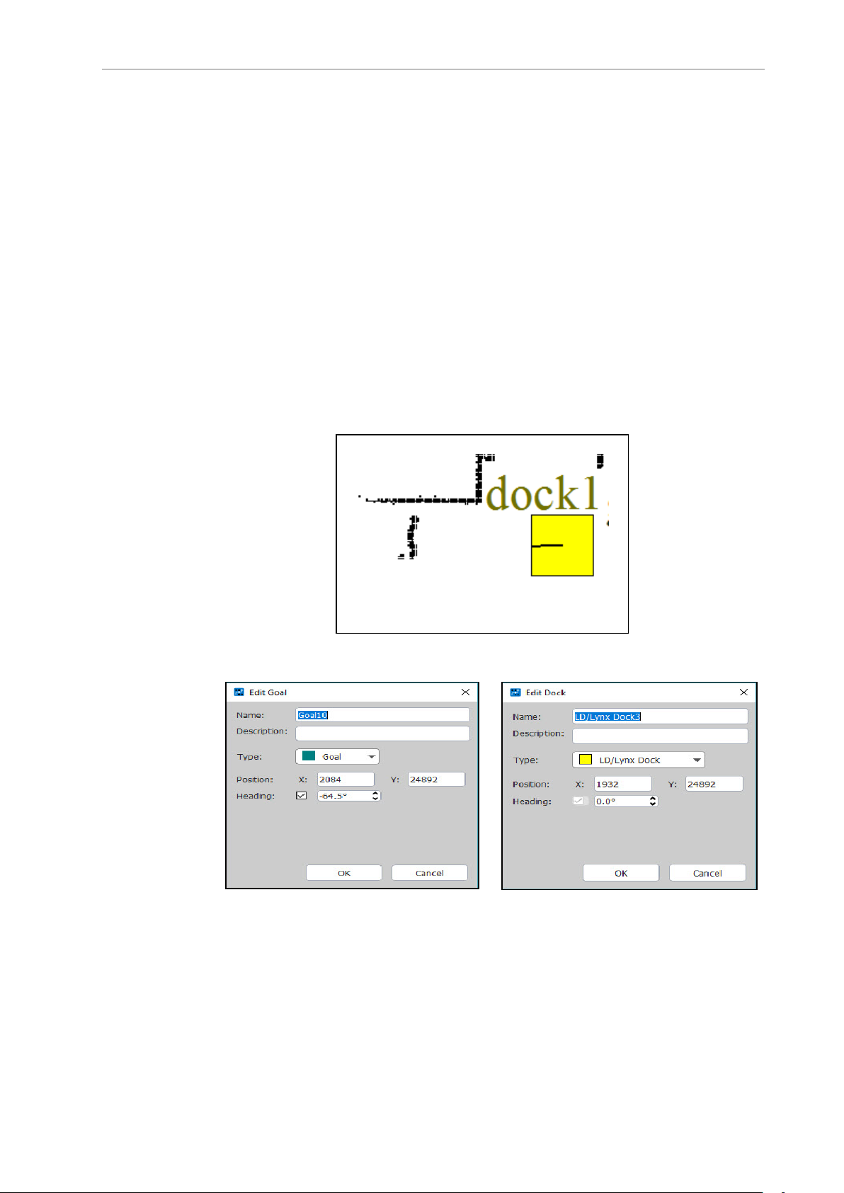
‘park at pickup/dropoff’ goals). Refer to Using Standby-Parking Goals on page
102.
o
Multi-Robot Standby (MRS): (also referred to as Taxi Line) allows (and enforces)
sequenced, orderly queuing of multiple AMRs from the same start (standby) position to the same goal. For more information, refer to Traffic Control Concepts on
page 202.
To create a goal/dock:
1.
With the map active, click on Draw tab >Goal or Draw tab >Dock.
2.
Click the mouse on the map where you want to locate the goal/dock. Then, while holding the left mouse button, drag the mouse around the goal/dock to set its heading.
NOTE: Place a dock object where the AMR should go to "look at" the
dock, not where the dock actually is. The dock object should be 1 to 1.5
meters in front of the dock, pointed at the dock. See the following figure.
Figure 7-6. Dock as Imaged by AMR
Figure 7-7. Edit Goal Dialog Box
3.
In the appropriate dialog box (Edit Goal or Edit Dock), enter the name of the goal/dock
Figure 7-8. Edit Dock Dialog Box
you want to add to the map, for example "Reception."
4.
Enter a description of this goal or dock (optional).
20569-020 Rev. D Fleet Operations Workspace Core User's Manual 100
 Loading...