

Page 1
PC Vision System 形FJシリーズ
形FJ-300□/形FJ-305□/形FJ-H300□/形FJ-H305□
形FJ-300□-10/形FJ-305□-10/形FJ-H300□-10/形FJ-H305□-10
取扱説明書(セットアップ)
このたびは、形FJシリーズをお買い上げいただきましてありがとうございます。
本書は、形FJ-300□/形FJ-305□/形FJ-H300□/形FJ-H305□/
形FJ-300□-10/形FJ-305□-10/形FJ-H300□-10/形FJ-H305□-10の取扱説明書です。
ご使用に際して、下記のことを守ってください。
・ 電気の知識を有する専門家が扱ってください。
・ 本書をよくお読みになり、十分にご理解のうえ、正しくご使用ください。
・ 本書はいつでも参照できるよう大切に保管してください。
※形式の□の意味は下記のとおりです。
0:NPN入出力タイプ 5:PNP入出力タイプ
OMRON Corporation2011AllRightsReserved.
©
Page 2

オムロン商品ご購入のお客さまへ
ご注文 ・ ご使用に際してのご承諾事項
当社制御機器商品をご注文いただく際、見積書、契約書、仕様書などに特記事項のない場合には、次の保証内容、責任の制限、適合用
途の条件などを適用いたします。
下記内容をご確認いただき、ご承諾のうえご注文およびご使用ください。
1.保証内容
①保証期間
本製品の保証期間は、ご購入後またはご指定の場所に納入後1年といたします。
②保証範囲
上記保証期間中に当社側の責により本製品に故障を生じた場合は、代替品の提供または故障品の修理対応を、
製品の購入場所において無償で実施いたします。
ただし、故障の原因が次に該当する場合は、この保証の対象範囲から除外いたします。
a)カタログまたは取扱説明書などに記載されている以外の条件・環境・取扱いならびにご使用による場合
b)本製品以外の原因の場合
c)当社以外による改造または修理による場合
d)本製品本来の使い方以外の使用による場合
e)当社出荷当時の科学・技術の水準では予見できなかった場合
f)その他、天災、災害など当社側の責ではない原因による場合
なお、ここでの保証は、本製品単体の保証を意味するもので、本製品の故障により誘発される損害は保証の対象
から除かれるものとします。
2.責任の制限
①本製品に起因して生じた特別損害、間接損害、または消極損害に関しては、当社はいかなる場合も責任を負いません。
②プログラミング可能な本製品については当社以外の者が行ったプログラム、またはそれにより生じた結果について当社は責任を負
いません。
3.適合用途の条件
①安全を確保する目的で直接的または間接的に人体を検出する用途に、本製品を使用しないでください。 同用途には、当社センサカ
タログに掲載している安全センサをご使用ください。
②本製品を他の商品と組み合わせて使用される場合、お客様が適合すべき規格 ・ 法規または規制をご確認ください。 また、お客様が
使用されるシステム、機械、装置への本製品の適合性は、お客様自身でご確認ください。 これらを実施されない場合は、当社は本製
品の適合性について責任を負いません。
③下記用途に使用される場合、当社営業担当者までご相談のうえ仕様書などによりご確認いただくとともに、定格 ・ 性能に対し余裕を
持った使い方や、万一故障があっても危険を最小にする安全回路などの安全対策を講じてください。
a)屋外の用途、潜在的な化学的汚染あるいは電気的妨害を被る用途またはカタログ ・ 取扱説明書などに記載のない条件や環境で
の使用
b)原子力制御設備、焼却設備、鉄道 ・ 航空 ・ 車両設備、医用機械、娯楽機械、安全装置、および行政機関や個別業界の規制に従う
設備
c)人命や財産に危険が及びうるシステム ・ 機械 ・ 装置
d)ガス、水道、電気の供給システムや24時間連続運転システムなど高い信頼性が必要な設備
e)その他、上記a) ~d)に準ずる、高度な安全性が必要とされる用途
④お客様が本製品を人命や財産に重大な危険を及ぼすような用途に使用される場合には、システム全体として危険を知らせたり、冗
長設計により必要な安全性を確保できるよう設計されていること、および本製品が全体の中で意図した用途に対して適切に配電 ・
設置されていることを必ず事前に確認してください。
⑤カタログなどに記載されているアプリケーション事例は参考用ですので、ご採用に際しては機器 ・ 装置の機能や安全性をご確認のう
え、ご使用ください。
⑥本製品が正しく使用されずお客様または第三者に不測の損害が生じることがないよう使用上の禁止事項および注意事項をすべて
ご理解のうえ守ってください。
4.仕様の変更
カタログ ・ 取扱説明書などに記載の商品の仕様および付属品は改善またはその他の事由により、必要に応じて、
変更する場合があります。 当社営業担当者までご相談のうえ本製品の実際の仕様をご確認ください。
5.適用範囲
以上の内容は、日本国内での取引および使用を前提としております。
日本国外での取引および使用に関しては、当社営業担当者までご相談ください。
1
Page 3
安全上のご注意
●安全に使用していただくための表示と意味について
この取扱説明書では、形FJシリーズコントローラ(以下コントローラと呼びます)を安全にご使用いただくために、注意事項を次のような表示と記
号で示しています。ここで示した注意事項は安全に関する重大な内容を記載しています。必ず守ってください。表示と記号は次のとおりです。
警告
注意
●図記号の意味
禁止
一般的な禁止を示します。
破裂注意
特定の条件において、破裂する可能性を示します。
高温注意
特定の条件において、高温による傷害が起こる可能性を示します。
●警告表示
正しい取扱いをしなければ、この危険のために、軽傷 ・ 中程度の傷害を負ったり、万一の場合には重症や死亡
にいたる恐れがあります。 また、同様に重大な物的損害を受ける恐れがあります。
正しい取扱いをしなければ、この危険のために、時に軽傷 ・ 中程度の傷害を負ったり、あるいは物的損害を受
ける恐れがあります。
感電注意
特定の条件において、感電する可能性を示します。
レーザ光線
レーザ光線による危害が生じる可能性を示します。
警告
本製品は必ず取扱説明書に従った方法でご使用ください。 指定された方法でご使用されない場合は、本製品の機能 ・ 性
能が損なわれる可能性があります。
安全を確保する目的で直接的または間接的に人体を検出する用途に本製品は使用できません。
人体保護用の検出装置として本製品を使用しないでください。
高電圧のため感電の恐れがあります。 ケースを開けないでください。
リチウムバッテリを内蔵しており、発火、破裂、燃焼により重度の傷害がまれに起こるおそれがあります。 廃棄時は産業廃
棄物として処理し、本体の分解、加圧変形、 100℃以上の加熱、焼却などは絶対にしないでください。
本製品は可視光を放射しており、まれに目に悪影響を及ぼす恐れがあります。 LEDの照射光を直視しないでください。
被写体が鏡面反射体の場合は、反射光が目に入らないようにしてください。
注意
万一の場合、軽い火傷の恐れがあります。
LEDが点灯中や電源を切った直後は、ケースが大変熱くなっており、ケースに触れないでください。
安全上の要点
●設置環境について
・ 引火性、爆発性ガスの環境では使用しないでください。
・ 通風口をふさがないように本体を設置してください。
・ 操作、保守の安全性を確保するため、高圧機器や動力機器から離して設置してください。
・ 取付けにおいて、ねじの締め付けは確実に行ってください。
●電源、配線について
・ 本書で指定した電源電圧で使用してください。
・ ケーブル、圧着端子は、指定サイズのものを使用してください。 撚り合わせただけの電線を直接端子台に接続しないでください。
-推奨電線サイズ:1.31 ~ 2.63mm
-端子ねじ : M4
・ 電源線の長さができるだけ短くなるように(最大10mまで)配線してください。
・ 電源は、高電圧が発生しないように対策(安全超低電圧回路)されている直流電源装置から供給してください。
・ D種接地 (接地抵抗100Ω以下) をしてください。
・ 接地点はできるだけ近くし、接地線の長さをできるだけ短くしてください。
・ 接地線はコントローラ単独で配線してください。 他の機器と共用したり、建物の梁に接続すると、悪影響を受けることがあります。
・ 電源投入前に再度配線を確認してください。
●その他
・ 専用のカメラ、ケーブル以外を使用しないでください。 誤動作、破損の恐れがあります。
・ カメラやケーブル類を着脱するときは、必ずコントローラの電源を切ってください。
・ この製品を分解したり、修理、改造しないでください。
・ 万一、異常を感じたときには、すぐに使用を中止し、電源を切った上で当社支店 ・ 営業所までご相談ください。
・ 通電中や電源を切った直後は、蛍光灯、ハロゲンランプに触らないでください。
・ 廃棄するときは、産業廃棄物として処理してください。
●法規と規格
本コントローラは、以下の規格に準拠しています。
EN規格(ヨーロッパ規格) EN61326-1
Electromagneticenvironment:Industrialelectromagneticenvironment
(EN/IEC61326-1Table2)
また本製品は、イミュニティ試験において、以下の条件を適用しています。
: モニタ表示において、文字が判読可能な映像の乱れは合格とする。
2
-圧着端子
8.5mm以下
8.5mm以下
2
Page 4
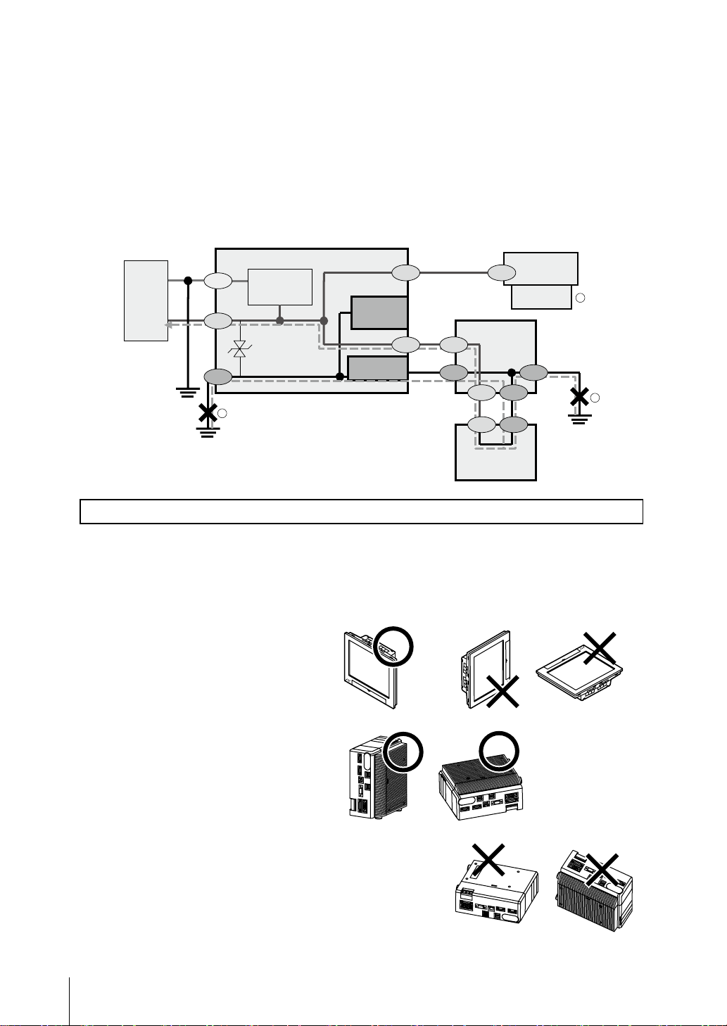
●接地について
・コントローラの電源回路は内部回路と絶縁されていません。
・24VDC電源のプラス(+)端子を接地する場合は、コントローラのFG端子、 PLCのFG端子を接地しないでください。 【①、②】
パソコンの外郭とSG(0V)がパソコン内部で接続されていますので、下図のような経路で電流が流れ焼損の原因になります。
・パソコンのようなSG(0V)とFGが短絡する経路が無い場合には、コントローラのFG端子を接地しても問題ありません。 PLCについては、ご
使用のPLCの仕様をご確認の上、配線してください。
・コントローラに接続するカメラは、必ず台座を使用して取り付けてください。 【③】
カメラ本体の外郭はSG(0V)ですので、台座が無い場合には、 SG(0V)とFGが短絡する恐れがあります。
・プラス(+)端子を接地する場合は、 SG(0V)(例 : カメラ本体、電源端子)を指等で触れないでください。 感電の恐れがあります。
・BOXタイプのコントローラ(形FJ-305□/形FJ-305□-10/形FJ-H305□/形FJ-H305□-10)を底面で取り付ける場合、底面がSG(0V)に接
続されていますので、お客様装置のFGと短絡します。 絶縁スペーサを用意しておりますので、弊社営業担当にお問い合わせください。
カメラケーブル
SG(0V)
SG SG
SG
SG
RS-232C
FG FG
RS-232C
電源
コントローラ
24V
0V
SG
FG
1
電源回路
FG
SG: Signal Ground
FG: Frame Ground
SG(0V)
パラレルI/O
コネクタ外郭
RS-232C
コネクタ外郭
使用上の注意
●設置場所、保管場所について
次のような場所に設置、保管してください。
・ 周囲温度が0~+50℃(保管時-20~+65℃)の場所 ・ 塵埃、塩分、鉄粉のない場所
・ 温度が急激に変化しない場所 (結露しない場所) ・ 振動や衝撃のない場所
・ 相対湿度が35~85%RHの場所 ・ 直射日光があたらない場所
・ 腐食性ガス、可燃性ガスのない場所 ・ 水 ・ 油 ・ 化学薬品の飛沫がない場所
●設置方向
放熱を良くするため、
右記の方向のみで設置してください。
●周囲温度
・通風を良くするため、コントローラの上下は
他の機器と50mm以上の間隔をあけてください。
左右は、他の機器またはコントローラと10mm以上
隙間をあけて設置してください。 ただし、上下左右に
隣接するものが発熱体でない場合、上部は同じく
50mm以上、下部および左右は取付け方法に従って
設置してください。
・ヒータ、トランスや大容量の抵抗など、発熱量の
高い機器の真上には取付けないでください。
・使用周囲温度は50℃以下にしてください。
・使用周囲温度が50℃に近い場合は、強制ファン
やクーラーを設置して、常時50℃を超えないようにして
ください。
●液晶一体タイプ
●BOXタイプ
カメラ
取付台座
(絶縁)
3
PLC
SG
FG
SG FG
外郭
パソコン
このような方向で設置しないでください
通風経路を確保するため、
側面(下になる面)に
脚を取付けてください。
このような方向で設置しないでください
2
3
Page 5

●耐ノイズ性
・高圧機器の設置されている盤内には取付けないでください。
・動力線からは、 200mm以上離してください。
●構成品の設置や取扱いについて
・信号線に触れる
端子部分やコネクタ内部の信号線に触れる場合は、静電気による破損を防ぐため、リストストラップなどを使用して帯電防止措置を行って
ください。
・USBメモリの取扱い
USBメモリを取外す場合は、データの読み/書き中でないことを確認して取外してください。 データの読み/書き中はUSBメモリ本体のLED
が点滅しますので、点灯状態になったことを確認して取外してください。
・電源を切る
処理を実行中であることを示すメッセージが画面に表示されているときは、電源をOFFしないでください。 メモリ上のデータが破損し、次に
起動したとき正常に動作しません。
・RESET信号について
電源ON直後にRESET入力をしないでください。 起動タイミングを同期させるためなどにRESET入力を使用する場合は、コントローラの電
源をONした後、 15秒以上おいてからRESET信号をONしてください。
・液晶一体タイプ (形FJ-300□/形FJ-300□-10/形FJ-H300□/形FJ-H300□-10)に使用している液晶ディスプレイは精密な技術で作ら
れておりますが、ごくわずかに画素欠陥がある場合があります。 これは液晶パネルの構造によるもので故障ではありません。
●メンテナンスについて
・お手入れをするときは、電源を切って、安全を確認してから行ってください。
・レンズの汚れは、レンズ専用の布、またはエアブラシを使用して取除いてください。
・装置の汚れは柔らかい布で軽く拭き取ってください。
・CCDの汚れは、エアブラシを使用して取除いてください。
・シンナー、ベンジンは使用しないてください。
●上位機器との通信について
本製品の起動を確認後、上位機器との通信を行ってください。
また、本製品の起動時は上位インターフェースから不定な信号が出る可能性がありますので、初期動作時はご使用機器の受信バッファを
クリアするなどの処置を実施してください。
■パッケージ内容の確認
・コントローラ......................................................1台
・取扱説明書(本書).......................................1冊
・SYSMAC会員 登録のご案内.................1枚
・取付金具(パネルマウント用)..................6個 ※液晶一体タイプのみ付属しています。
・タッチペン.........................................................1本 ※液晶一体タイプのみ、コントローラ内部に収納されています。
■米国カリフォルニア州過塩素酸塩規制について
この製品はカリフォルニア州法で規制されている過塩素酸塩を含むリチウムバッテリーを内蔵しておりますので、この州法への対応をして
ください。
詳しくは、下記URLをご覧ください。
www.dtsc.ca.gov/hazardouswaste/perchlorate
4
Page 6
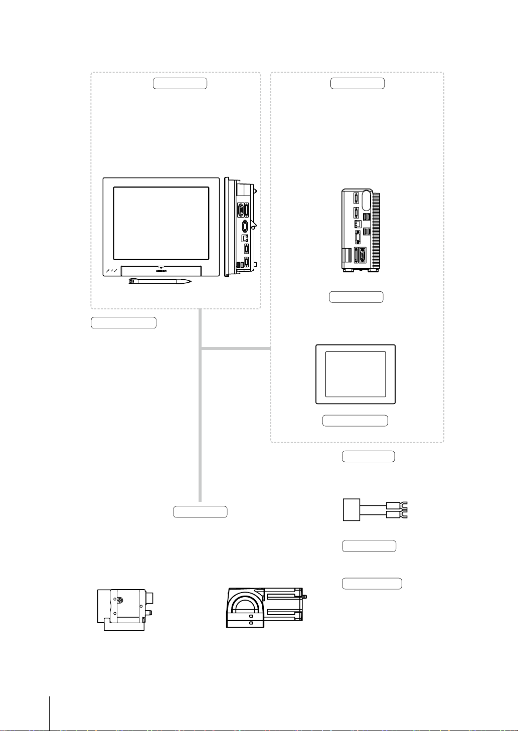
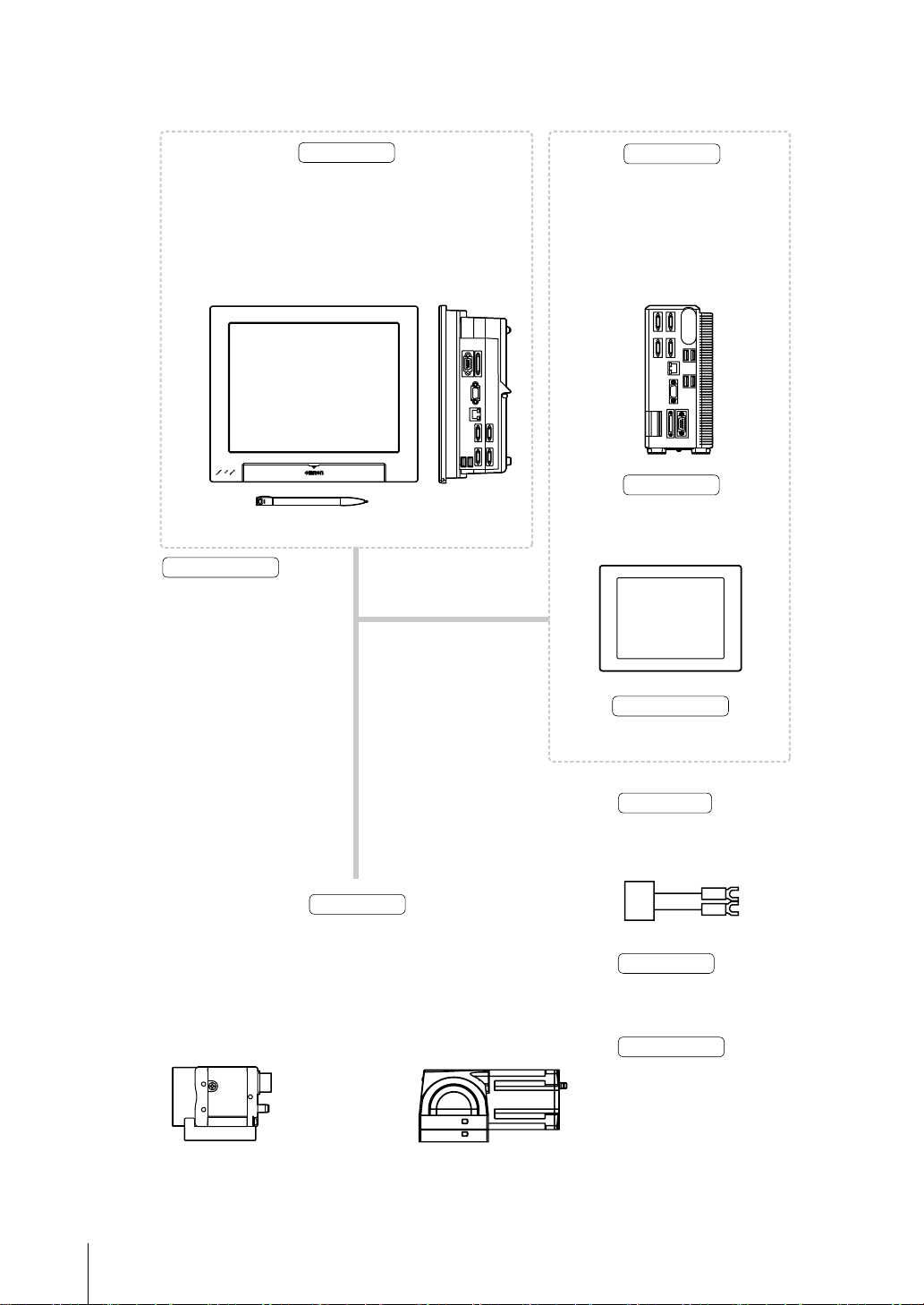
■基本構成 カメラ2chタイプ
*印は専用品です。 これら以外は使用できません。
*
コントローラ
画像の確認や条件設定用メニューを表示するために使用
します。 また、設定条件に従った画像処理を行い、計測結
果を出力する部分です。
液晶一体タイプ
形FJ-3000/形FJ-3005
形FJ-H3000/形FJ-H3005
正面 右側面
*
コントローラ
設定条件に従った画像処理を行い、
計測結果を出力する部分です。
BOXタイプ
形FJ-3050/形FJ-3055
形FJ-H3050/形FJ-H3055
タッチペン(付属品)
*
カメラケーブル
カメラケーブル
カメラケーブル
形FZ-VS(2m、5m、10m)
形FZ-VS3(2m、3m、5m、10m)
耐屈曲カメラケーブル
耐屈曲カメラケーブル
形FZ-VSB(2m、5m、10m)
形FZ-VSB3(2m、3m、5m、10m)
ライトアングルカメラケーブル
ライトアングルカメラケーブル
形FZ-VSL(2m、5m、10m)
形FZ-VSL3(2m、3m、5m、10m)
長距離カメラケーブル
耐屈曲ライトアングルカメラケーブル
形FZ-VS2(15m)
形FZ-VSLB3(2m、3m、5m、10m)
長距離ライトアングルカメラケーブル
形FZ-VSL2(15m)
長距離カメラケーブル
形FZ-VS4(15m)
長距離ライトアングルカメラケーブル
形FZ-VSL4(15m)
インテリジェントカメラ
形FZ-SLC15/形FZ-SLC100
*
計測物を画像として取込む部分です。
単体カメラ
形FZ-SC/形FZ-S/形FZ-SC2M
形FZ-S2M
形FZ-SC5M2/形FZ-S5M2
形FZ-SFC/形FZ-SF/形FZ-SPC
形FZ-SP/形FZ-SHC/形FZ-SH
カメラ
画像の確認や条件設定用メニュー
を表示するために使用します。
*
オートフォーカスカメラ
形FZ-SZC15/形FZ-SZC100
インテリジェントコンパクトカメラ
形FZ-SQ010F/形FZ-SQ050F
形FZ-SQ100F/形FZ-SQ100N
*
液晶モニタ
形FZ-M08(8.4インチ)
モニタケーブル
形FZ-VM(2m、5m)
電源装置
推奨品
オムロン(株)製
形S8VS-12024
周辺機器
*USBメモリ
形FZ-MEM2G/FZ-MEM8G
入力デバイス
マウス、トラックボール
(USBインタフェースの市販品)
5
Page 7
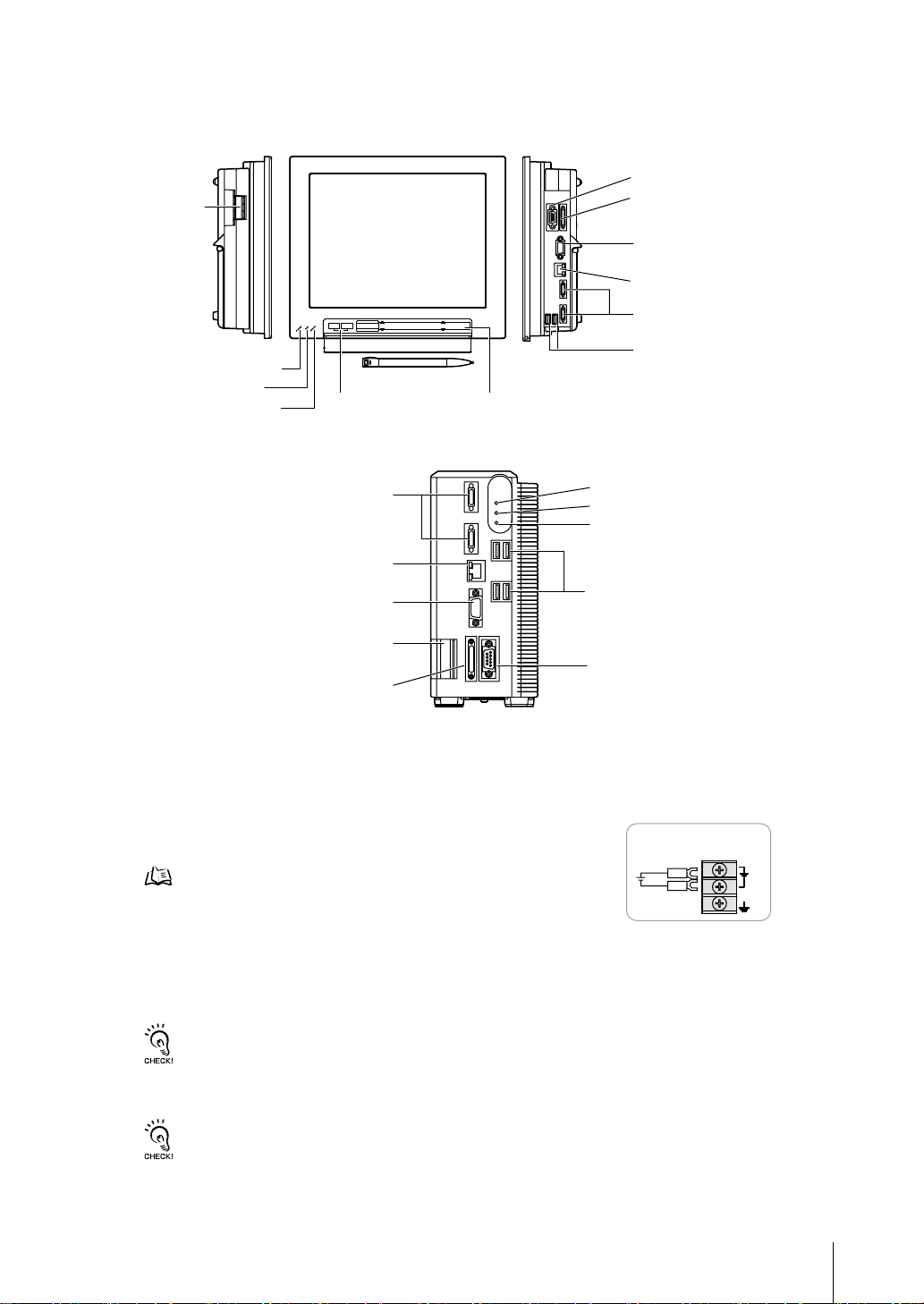
■各部の名称とはたらき
●液晶一体タイプ 形FJ-3000/形FJ-3005/形FJ-H3000/形FJ-H3005
左側面 正面 右側面
⑥⑦
電源・
接地端子
①
POWER LED
②
RUN LED
③
ERROR LED
●BOXタイプ 形FJ-3050/形FJ-3055/形FJ-H3050/形FJ-H3055
⑪
イーサネット接続コネクタ
⑧
モニタ接続コネクタ(アナログRGB)
⑩
⑤
カメラコネクタ
USBコネクタ
⑫
タッチペン (収納)
⑨
RS-232C/422接続コネクタ
④
入出力コネクタ
⑧
モニタ接続コネクタ
⑪
イーサネット接続コネクタ
⑤
カメラコネクタ
⑩
USBコネクタ
①
POWER LED
②
RUN LED
③
ERROR LED
⑩
USBコネクタ
(制御線、データ線)
(アナログRGB)
⑥⑦
電源・接地端子
⑨
④
入出力コネクタ(制御線、データ線)
①
通電中、点灯します。
②
表示中のレイアウトにしたがって点灯/消灯します。
③
異常が発生したときに点灯します。
④
同期センサ、プログラマブルコントローラなどの外部装置と接続します。
⑤
カメラを接続します。
⑥
DC電源を接続します。他の機器とは独立して配線してください。配線後は、
端子カバー(透明)を元の場所に取付けてください。
電源、配線についてp.2
⑦
接地線を配線します。 必ずコントローラ単独で配線してください。
⑧
モニタを接続します。
⑨
パソコン、プログラマブルコントローラなどの外部装置と接続します。
⑩
トラックボール、マウス、 USBメモリと接続します。 計4ポートありますが、どのポートを使用しても問題ありません。
RS-232C/422接続コネクタ
電源の配線
㪉㪋㪭㪛㪚
㪂
㪄
ただし、 USBメモリは隣り合ったポートに接続しないでください。 USBメモリ同士が接触し誤動作や破損の恐れが
あります。
・ USBコネクタの接続対象は右記のとおりです。 ・ 市販のトラックボール、マウス ・ USBメモリ
・ 計測稼動中にUSB機器を抜き差ししないでください。 計測時間に影響が出る可能性があります。
⑪
パソコンと接続します。
⑫
操作用のタッチペンが収納されています。(液晶一体タイプのみ)
・ タッチペンは必ずコントローラに向かってペン先が右向きなるよう収納してください。
・取出す時はペンの左側 (持ち手) を奥へ押してください。 ペンの右側 (ペン先) が前に飛出しますので、摘んで取出してください。
6
Page 8
■基本構成 カメラ4chタイプ
*印は専用品です。 これら以外は使用できません。
*
コントローラ
画像の確認や条件設定用メニューを表示するために使用します。 また、
設定条件に従った画像処理を行い、計測結果を出力する部分です。
液晶一体タイプ
形FJ-3000-10/形FJ-3005-10
形FJ-H3000-10/形FJ-H3005-10
正面 右側面
タッチペン(付属品)
*
カメラケーブル
カメラケーブル
カメラケーブル
形FZ-VS3(2m、3m、5m、10m)
形FZ-VS(2m、5m、10m)
耐屈曲カメラケーブル
耐屈曲カメラケーブル
形FZ-VSB3(2m、3m、5m、10m)
形FZ-VSB(2m、5m、10m)
ライトアングルカメラケーブル
ライトアングルカメラケーブル
形FZ-VSL(2m、5m、10m)
形FZ-VSL3(2m、3m、5m、10m)
長距離カメラケーブル
耐屈曲ライトアングルカメラケーブル
形FZ-VS2(15m)
形FZ-VSLB3(2m、3m、5m、10m)
長距離ライトアングルカメラケーブル
長距離カメラケーブル
形FZ-VSL2(15m)
形FZ-VS4(15m)
長距離ライトアングルカメラケーブル
形FZ-VSL4(15m)
インテリジェントカメラ
形FZ-SLC15/形FZ-SLC100
*
計測物を画像として取込む部分です。
カメラ
オートフォーカスカメラ
形FZ-SZC15/形FZ-SZC100
*
コントローラ
設定条件に従った画像処理を行い、計測
結果を出力する部分です。
BOXタイプ
形FJ-3050-10/形FJ-3055-10
形FJ-H3050-10/形FJ-H3055-10
*
液晶モニタ
画像の確認や条件設定用メニュー
を表示するために使用します。
形FZ-M08(8.4インチ)
*
モニタケーブル
形FZ-VM(2m、5m)
電源装置
推奨品
オムロン(株)製
S8VS-18024
単体カメラ
形FZ-SC/形FZ-S/形FZ-SC2M
形FZ-S2M
形FZ-SC5M2/形FZ-S5M2/形FZ-SFC
形FZ-SF/形FZ-SPC/形FZ-SP
形FZ-SHC/形FZ-SH
インテリジェントコンパクトカメラ
形FZ-SQ010F/形FZ-SQ050F
形FZ-SQ100F/形FZ-SQ100N
周辺機器
*USBメモリ
形FZ-MEM2G/FZ-MEM8G
入力デバイス
マウス、トラックボール
(USBインタフェースの市販品)
7
Page 9
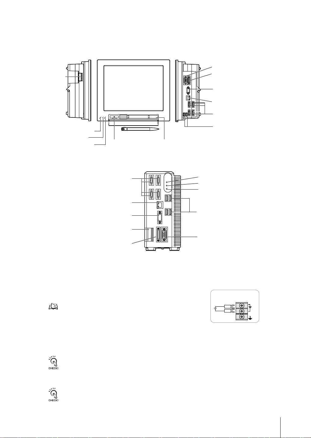
■各部の名称とはたらき
●液晶一体タイプ 形FJ-3000-10/形FJ-3005-10/形FJ-H3000-10/形FJ-H3005-10
左側面 正面 右側面
⑥⑦
電源・
接地端子
①
POWER LED
②
RUN LED
③
ERROR LED
●BOXタイプ 形FJ-3050-10/形FJ-3055-10/形FJ-H3050-10/形FJ-H3055-10
⑪
イーサネット接続コネクタ
⑧
モニタ接続コネクタ(アナログRGB)
⑩
USBコネクタ
⑤
カメラコネクタ
⑫
タッチペン (収納)
①
②
③
⑩
USBコネクタ
⑨
RS-232C/422接続コネクタ
④
入出力コネクタ
(制御線、データ線)
⑧
モニタ接続コネクタ
(アナログRGB)
⑪
イーサネット接続コネクタ
⑤
カメラコネクタ
⑩
USBコネクタ
POWER LED
RUN LED
ERROR LED
⑥⑦
電源・接地端子
⑨
④
入出力コネクタ(制御線、データ線)
①
通電中、点灯します。
②
表示中のレイアウトにしたがって点灯/消灯します。
③
異常が発生したときに点灯します。
④
同期センサ、プログラマブルコントローラなどの外部装置と接続します。
⑤
カメラを接続します。
⑥
DC電源を接続します。他の機器とは独立して配線してください。配線後は、
端子カバー(透明)を元の場所に取付けてください。
電源、配線についてp.2
⑦
接地線を配線します。 必ずコントローラ単独で配線してください。
⑧
モニタを接続します。
⑨
パソコン、プログラマブルコントローラなどの外部装置と接続します。
⑩
トラックボール、マウス、 USBメモリと接続します。 計4ポートありますが、どのポートを使用しても問題ありません。
RS-232C/422接続コネクタ
電源の配線
㪉㪋㪭㪛㪚
㪂
㪄
ただし、 USBメモリは隣り合ったポートに接続しないでください。 USBメモリ同士が接触し誤動作や破損の恐れが
あります。
・ USBコネクタの接続対象は右記のとおりです。 ・ 市販のトラックボール、マウス ・ USBメモリ
・ 計測稼動中にUSB機器を抜き差ししないでください。 計測時間に影響が出る可能性があります。
⑪
パソコンと接続します。
⑫
操作用のタッチペンが収納されています。(液晶一体タイプのみ)
・ タッチペンは必ずコントローラに向かってペン先が右向きなるよう収納してください。
・取出す時はペンの左側 (持ち手) を奥へ押してください。 ペンの右側 (ペン先) が前に飛出しますので、摘んで取出してください。
8
Page 10
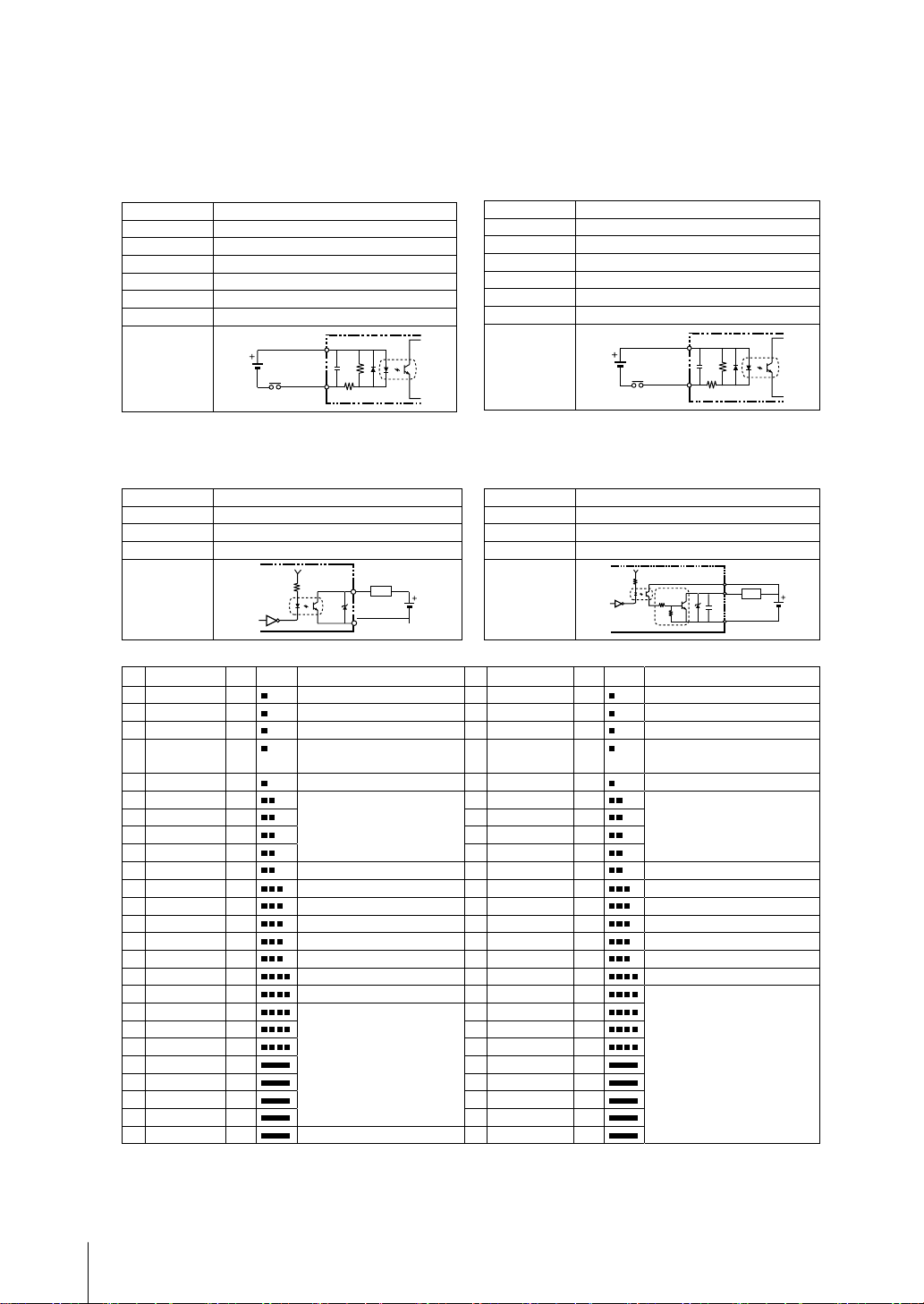
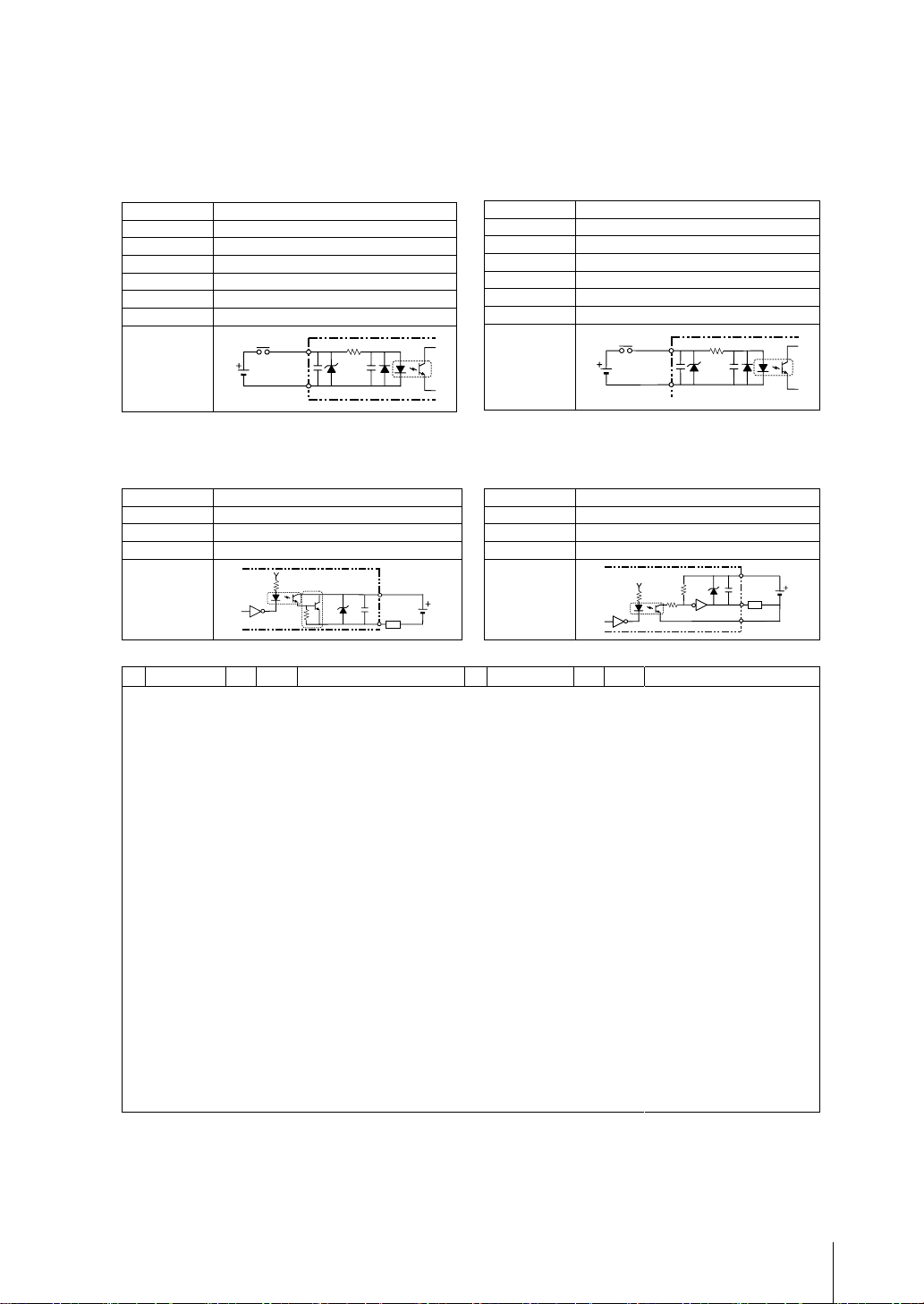
■パラレルインタフェース
COM OUT
NPN入出力タイプ形FJ-3000/形FJ-3050/形FJ-H3000/形FJ-H3050
形FJ-3000-10/形FJ-3050-10/形FJ-H3000-10/形FJ-H3050-10
●内部仕様
【入力】対象信号/ RESET、 DI0~DI7、 DSA0、 DSA1
入力電圧
ON電流 ※1
ON電圧 ※1
OFF電流※2
OFF電圧※2
ONディレー 5ms以下
OFFディレー 0.7ms以下
内部回路図
※1ON電流/ON電圧 OFF→ON状態にさせる電流値または電圧値のことです。 ON電圧の値は、 COMINと各入力端子間の電位差となります。
※2OFF電流/OFF電圧 ON→OFF状態にさせる電流値または電圧値のことです。 OFF電圧の値は、 COMINと各入力端子間の電位差となります。
【出力】対象信号/
出力電圧
負荷電流
ON残留電圧 2V以下
OFF漏れ電流 0.2mA以下
内部回路図
DC12~24V ±10%
最小5mA
最小8.8V
最大0.5mA
最大1.1V
COM IN
BUSY0、 RUN/BUSY1、 OR0~1、 GATE0~1、
ERROR、 DO0~15、 READY0~1
DC12~24V ±10%
45mA以下
各出力端子
負荷
COM OUT
【入力】対象信号/
入力電圧
ON電流 ※1
ON電圧 ※1
OFF電流※2
OFF電圧※2
ONディレー 0.1ms以下
OFFディレー 0.1ms以下
内部回路図
【出力】対象信号/
STGOUT0~3使用時はCOM IN端子を接続してください。
出力電圧
負荷電流
ON残留電圧 2V以下
OFF漏れ電流 0.2mA以下
内部回路図
STEP0/ENCTRIG_Z0、 STEP1/ENCTRIG_Z1、
ENCTRIG_A0~1、 ENCTRIG_B0~1
DC12~24V ±10%
最小5mA
最小8.8V
最大0.5mA
最大0.8V
COM IN
各入力端子各入力端子
STGOUT0~3
DC12~24V ±10%
45mA以下
COM IN
負荷
各出力端子
●入出力コネクタ
No.
信号名
A1
COMIN 橙 入力信号用コモン
A2
ENCTRIG_A1(※2)
A3
ENCTRIG_B1(※2)
A4
STEP1(※2)/
ENCTRIG_Z1(※2)
A5
DSA1(※2) 桃 データ送信要求信号
A6
DI1 橙 コマンド入力
A7
DI3 灰
A8
DI5 白
A9
DI7 黄
A10
STGOUT1 桃 ストロボトリガ出力(※1)
A11
STGOUT3 橙 ストロボトリガ出力(※1)
A12
ERROR 灰 エラー発生時にON
A13
COMOUT1 白 制御信号用コモン
A14
GATE1(※2) 黄 設定した出力時間中ON
A15
OR1(※2) 桃 総合判定結果
A16
READY1(※2) 橙 画像入力が許可されるときON
A17
COMOUT2 灰 出力信号用コモン
A18
DO1 白 データ出力
A19
DO3 黄
A20
DO5 桃
A21
DO7 橙
A22
DO9 灰
A23
DO11 白
A24
DO13 黄
A25
COMOUT3 桃 出力信号用コモン
・ 出力用コモン端子の対応
COMOUT1 : STGOUT0~3、 RUN/BUSY1、 ERROR、 BUSY0、 OR0~1、 GATE0~1 COMOUT2 : READY0~1、 DO0~7 COMOUT3 : DO8~15
※1コントローラにストロボ装置を接続したい場合に使用する信号です。 カメラ2chタイプでは、 STGOUT0、 STGOUT1のみ使用できます。
※22ラインランダムトリガモード時のみ使用できます。
線色
マーク(赤)
灰 エンコーダトリガ入力(A相)
白 エンコーダトリガ入力(B相)
黄 計測トリガ入力/
エンコーダトリガ入力(Z相)
役割
No.
信号名
B1
RESET 橙 コントローラ再起動
B2
ENCTRIG_A0 灰 エンコーダトリガ入力 (A相)
B3
ENCTRIG_B0 白
B4
STEP0/
ENCTRIG_Z0
B5
DSA0 桃 データ送信要求信号
B6
DI0 橙 コマンド入力
B7
DI2 灰
B8
DI4 白
B9
DI6 黄
B10
STGOUT0 桃 ストロボトリガ出力(※1)
B11
STGOUT2 橙 ストロボトリガ出力(※1)
B12
RUN/BUSY1(※2)
B13
BUSY0 白 処理実行中にON
B14
GATE0 黄 設定した出力時間中ON
B15
OR0 桃 総合判定結果
B16
READY0 橙 画像入力が許可されるときON
B17
DO0 灰 データ出力
B18
DO2 白
B19
DO4 黄
B20
DO6 桃
B21
DO8 橙
B22
DO10 灰
B23
DO12 白
B24
DO14 黄
B25
DO15 桃
線色
マーク(黒)
黄 計測トリガ入力/
灰
エンコーダトリガ入力 (B相)
エンコーダトリガ入力 (Z相)
レイアウト設定によりON/処理実行中にON
役割
9
Page 11
COM OUT
COM IN
■パラレルインタフェース
PNP入出力タイプ形FJ-3005/形FJ-3055/形FJ-H3005/形FJ-H3055
形FJ-3005-10/形FJ-3055-10/形FJ-H3005-10/形FJ-H3055-10
●内部仕様
【入力】対象信号/ RESET、 DI0~DI7、 DSA0、 DSA1
入力電圧
ON電流 ※1
ON電圧 ※1
OFF電流※2
OFF電圧※2
ONディレー 5ms以下
OFFディレー 0.7ms以下
内部回路図
※1ON電流/ON電圧 OFF→ON状態にさせる電流値または電圧値のことです。 ON電圧の値は、 COMINと各入力端子間の電位差となります。
※2OFF電流/OFF電圧 ON→OFF状態にさせる電流値または電圧値のことです。 OFF電圧の値は、 COMINと各入力端子間の電位差となります。
【出力】対象信号/
出力電圧
負荷電流
ON残留電圧 2V以下
OFF漏れ電流 0.2mA以下
内部回路図
DC12~24V ±10%
最小5mA
最小8.8V
最大0.5mA
最大1.1V
COM IN
BUSY0、 RUN/BUSY1、 OR0~1、 GATE0~1、
ERROR、 DO0~15、 READY0~1
DC12~24V ±10%
45mA以下
COM OUT
負荷
各入力端子
【入力】対象信号/
入力電圧
ON電流 ※1
ON電圧 ※1
OFF電流※2
OFF電圧※2
ONディレー 0.1ms以下
OFFディレー 0.1ms以下
内部回路図
【出力】対象信号/
STGOUT0~3使用時はCOM IN端子を接続してください。
出力電圧
負荷電流
ON残留電圧 2V以下
OFF漏れ電流 0.2mA以下
内部回路図
STEP0/ENCTRIG_Z0、 STEP1/ENCTRIG_Z1、
ENCTRIG_A0~1、 ENCTRIG_B0~1
DC12~24V ±10%
最小5mA
最小8.8V
最大0.5mA
最大0.8V
各入力端子各入力端子
STGOUT0~3
DC12~24V ±10%
45mA以下
各入力端子
負荷
COM IN
㩷
●入出力コネクタ
No.
信号名
線色
マーク(赤)
役割
No.
信号名
線色
マーク(黒)
役割
入出力コネクタの配線はNPNタイプと同じです。
10
Page 12
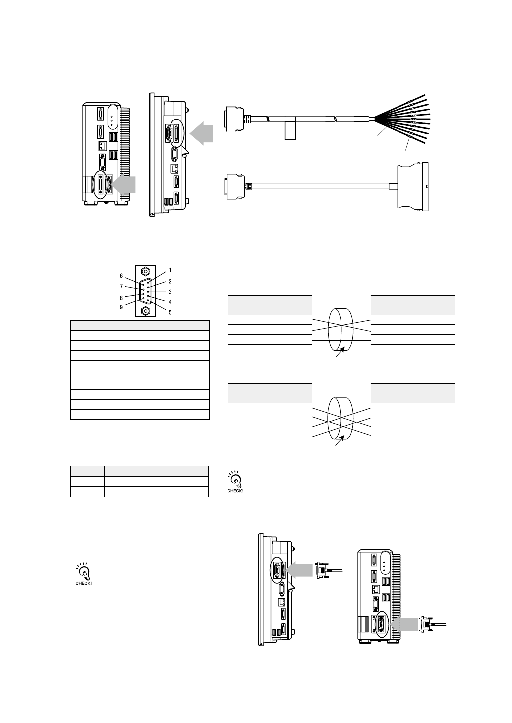
●コネクタ
パラレルI/Oケーブル形FZ-VP、 FZ-VPX(別売)を接続します。
BOXタイプ
液晶一体タイプ
■シリアルインタフェース
●コネクタ
ピンNo. 信号名 役割
1 RDB(+) RS-422用
2 RD/RDA(-)
3 SD/SDA(-)
4 SDB(+)
5 GND
6 NC
7 NC
8 NC
9 NC
適合するコネクタをご用意ください。
・ 推奨品
メーカー 形式
ソケット
フード
オムロン (株)
オムロン (株)
RS-232C用/RS-422用
RS-232C用/RS-422用
RS-422用
信号用接地
無接続
無接続
無接続
無接続
形XM3D-0921
形XM2S-0913
形FZ-VP(2m、5m)
線色
No.
マーク
形FZ-VPX(2m、5m)
●配線
ケーブル長は、 15m以下にしてください。
・ RS-232C
コントローラ 接続する外部装置
信号名 ピンNo. ピンNo. 信号名
RD 2
SD 3
GND 5
シールドされたケーブルを使用してください。
・ RS-422
コントローラ 接続する外部装置
信号名 ピンNo. ピンNo. 信号名
RDB(+) 1
RDA(-) 2
SDA(-) 3
SDB(+) 4
シールドされたケーブルを使用してください。
ピン番号は、接続する外部装置の種類や機種によって異なります。 お手持ち
のプログラマブルコントローラやパソコンの取扱説明書を確認してください。
*
*
*
RS/CS制御はできません。
*
*
*
*
RD
SD
GND
RDA(-)
RDB(+)
SDB(+)
SDA(-)
11
●接続方法
コネクタの向きを合わせ、 まっすぐに差込み、
コネクタの両端のねじで固定してください。
電源を切った状態でケーブルを着脱してください。
周辺機器の破損の原因になります。
液晶一体タイプ
BOXタイプ
Page 13
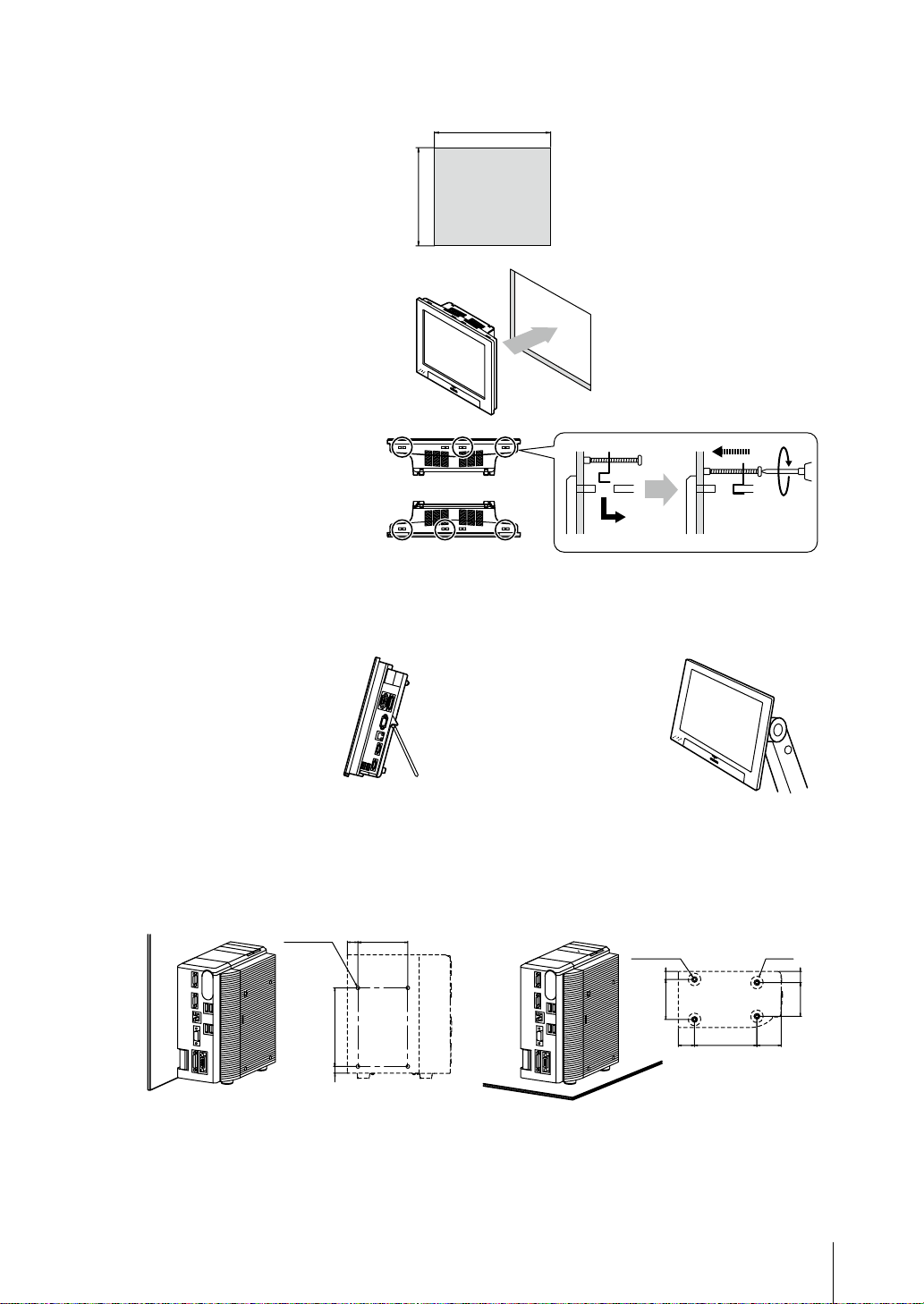
■取付け
●液晶一体タイプ
・ パネル取付け
①
パネルに取付け用の穴をあけます。
パネルの板厚範囲 : 1.6 ~ 4.8mm
パネルの材質 : 金属製 (鉄、アルミ、
またはステンレス)
②
液晶一体タイプコントローラを
パネル前面から挿入します。
③
付属の取付金具で、液晶一体タイプ
コントローラとパネルを固定します。
締付トルク : 0.5 ~ 0.6Nm
上面
下面
1
0
247
297
1
0
(単位:mm)
※バリなきこと
・ 卓上コントローラスタンド(別売)取付け
別売りの卓上コントローラスタ
ンド形FZ-DSを背面に装着す
ることにより、 卓上に据え置き
することができます。
※詳しくは卓上コントローラスタンドの
取扱説明書をご参照ください。
・ VESAアタッチメント(別売)取付け
別売りのVESAアタッチメント
形FZ-VESAを背面に装着す
ることによりVESA規格のマ
ウントができます。
※詳しくはVESAアタッチメントの取
扱説明書をご参照ください。
● BOX タイプ
・ 側面取付け ・ 底面取付け
(17)
4-M4 深さ6
80r0.25
126r0.25
(11)
※底面で固定する場合は通風経路を確保するため、
脚を外さず共締めしてください。
4-M4 深さ6
(13)
64r0.25
(26)
100r0.25
4-㱢 20
()
39
(18)
54r0.25
12
Page 14
()
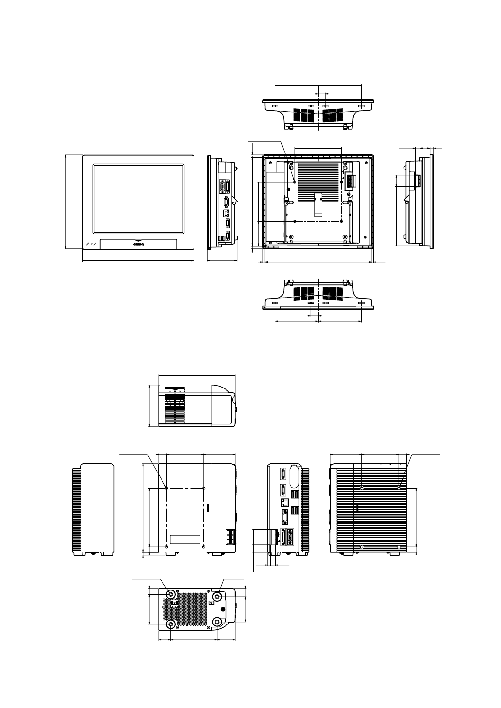
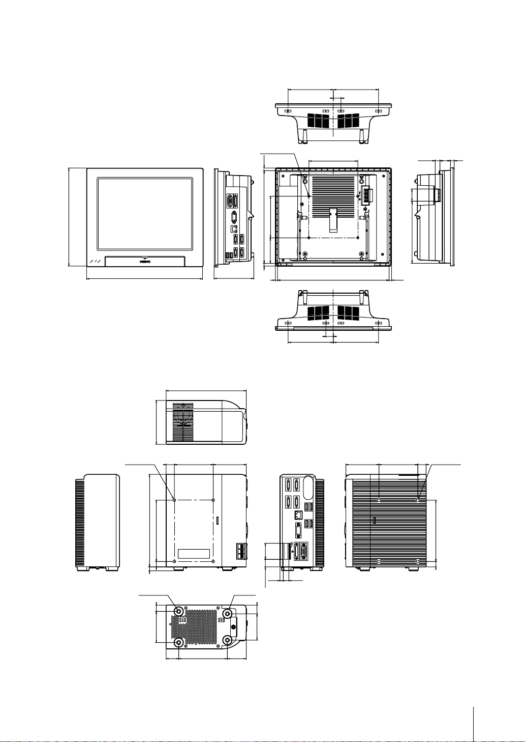
■コントローラ外形寸法
●液晶一体タイプ 形FJ-3000/形FJ-3005/形FJ-H3000/形FJ-H3005
4-M 3
7
()
260
308
83
246
7
110
68
6
●BOXタイプ 形FJ-3050/形FJ-3055/形FJ-H3050/形FJ-H3055
深さ6
120 120
20
130
296
20
120 120
㪂
㪄
()
6
(単位mm)
28.412.8 10
33
163.5
()
4-M4
深さ6
4-M4
190
8
90
11 126
深さ6
13
64
17 80
26
100
165
()
68
()
39
4-㱢20
33
()
6.8
15.45
()
1854
11.5
(単位mm)
()
68
㪂
㪄
80 17
4-M4
126
11
深さ6
13
Page 15
100
26
260
()
120 120
■コントローラ外形寸法
●液晶一体タイプ 形FJ-3000-10/形FJ-3005-10/形FJ-H3000-10/形FJ-H3005-10
20
4-M 3
308
7
()
246
104
7
深さ6
110
68
6
130
296
20
120 120
●BOXタイプ 形FJ-3050-10/形FJ-3055-10/形FJ-H3050-10/形FJ-H3055-10
㪂
㪄
33
163.5
()
()
6
(単位mm)
28.412.8 10
4-M4
深さ6
4-M4
190
8
90
11 126
深さ6
13
64
17 80
165
()
68
()
39
4-㱢20
33
()
6.8
15.45
()
1854
11.5
(単位mm)
()
68
㪂
㪄
80 17
4-M4
126
11
深さ6
14
Page 16

■コントローラの仕様
操作 液晶一体タイプ :タッチペン、マウスなどによる操作
BOXタイプ :マウスなどによる操作
シリアル通信 RS-232C/422:1CH
ネットワーク通信 Ethernet100BASE-TX/10BASE-T
EtherNet/IP通信 Ethernetポート使用
伝送速度 : 100Mbps(100BASE-TX)
パラレル入出力
モニタI/F 液晶一体タイプ :コントローラと一体型12.1インチTFTカラー液晶 (解像度XGA1024×768)
USBI/F 4CH (USB1.1/2.0準拠)
電源電圧 DC24V(DC20.4 ~ 26.4V)
消費電流
(DC24.0V使用時)
絶縁抵抗
耐電圧 DC外部端子一括とアース端子間 :AC1000V 50/60Hz
漏れ電流 10mA以下
耐ノイズ性 1kV、パルス立上がり :5ns パルス幅 :50ns
耐振動 10 ~ 150Hz 片振幅0.1mm(加速度最大15m/s
耐衝撃 150m/s
周囲温度範囲 動作時 : 0 ~+50℃
周囲湿度範囲 動作時 ・ 保存時:各35 ~ 85% RH(ただし結露しないこと)
周囲雰囲気 腐食性ガスのないこと
接 地 D種接地 (接地抵抗100Ω以下)*従来の第三種接地
保護構造 IEC60529規格IP20
ケースの材質 ABS
質 量 液晶一体タイプ : 約3.4kg BOXタイプ : 約1.9kg
入力17点 (RESET、STEP0/ENCTRIG_Z0、STEP1/ENCTRIG_Z1、DSA0~1、ENCTRIG_A0~1、ENCTRIG_B0~1、DI0~7)
出力29点 (RUN/BUSY1、 BUSY0、 GATE0~1、 OR0~1、 READY0~1、 ERROR、 STGOUT0~3、 DO0~15)
※STGOUT2、 3はカメラ4chタイプのみ
BOXタイプ :アナログRGBビデオ出力1ch (解像度XGA1024×768)
接続カメラの種類により消費電流が異なります。
形FZ-S□/形FZ-S□2M/形FZ-S□5M2/形FZ-SF□/形FZ-SP□/形FZ-SH□ 接続時 :
カメラ2chタイプ : 約3.7A以下 カメラ4chタイプ : 約4.9A以下
DC外部端子一括とアース端子間:20MΩ以上(DC100Vメガにて ただし、内蔵サージアブソーバを外した場合)
バースト継続時間 :15ms 周期 :300ms
2
6方向各3回
周囲温度を設定可能、設定に応じて冷却ファンの回転速度を切替
0 ~+45℃ : 低速回転 0 ~+50℃ : 高速回転
保存時 : -20 ~+65℃(ただし氷結 ・ 結露しないこと)
2
)3方向各8分10回
055‑
977‑6389
Page 17

PC Vision System
FJ-300_/FJ-305_/FJ-H300_/FJ-H305_
FJ-300_-10/FJ-305_-10/FJ-H300_-10/FJ-H305_-10
FJ Series
INSTRUCTION MANUAL
Thank you for selecting the FJ Series PC Vision System.
This manual explains how to use the FJ Series PC Vision System.
When using the FJ Series PC Vision System, make sure to observe the following:
The FJ Series PC Vision System must be operated by personnel knowledgeable
•
in electrical engineering.
To ensure correct use, please read this manual thoroughly to deepen your
•
understanding of the product.
Please keep this manual in a safe place so that it can be referred to whenever necessary.
•
The meaning of “_” in model is described below.
*
0:NPN I/O type 5:PNP I/O type
TRACEABILITY INFORMATION:
Importer in EU:
Omron Europe B.V.
Wegalaan 67-69 2132 JD Hoofddorp,The Netherlands
Manufacturer:
Omron Corporation,
Shiokoji Horikawa,Shimogyo-ku, Kyoto 600-8530 JAPAN
The following notice applies only to products that carry the CE mark:
Notice:
This is a class A product. In residential areas it may cause radio interference,
in which case the user may be required to take adequate measures to reduce
interference.
© OMRON Corporation 2011 All Rights Reserved.
(SETUP)
Page 18

READ AND UNDERSTAND THIS DOCUMENT
Please read and understand this document before using the products. Please consult your OMRON
representative if you have any questions or comments.
WARRANTY
OMRON’s exclusive warranty is that the products are free from defects in materials and workmanship
for a period of one year (or other period if specied) from date of sale by OMRON.
OMRON MAKES NO WARRANTY OR REPRESENTATION, EXPRESS OR IMPLIED, REGARDING
NON-INFRINGEMENT, MERCHANTABILITY, OR FITNESS FOR PARTICULAR PURPOSE OF THE
PRODUCTS. ANY BUYER OR USER ACKNOWLEDGES THAT THE BUYER OR USER ALONE HAS
DETERMINED THAT THE PRODUCTS WILL SUITABLY MEET THE REQUIREMENTS OF THEIR
INTENDED USE. OMRON DISCLAIMS ALL OTHER WARRANTIES, EXPRESS OR IMPLIED.
LIMITATIONS OF LIABILITY
OMRON SHALL NOT BE RESPONSIBLE FOR SPECIAL, INDIRECT, OR CONSEQUENTIAL
DAMAGES, LOSS OF PROFITS OR COMMERCIAL LOSS IN ANY WAY CONNECTED WITH THE
PRODUCTS, WHETHER SUCH CLAIM IS BASED ON CONTRACT, WARRANTY, NEGLIGENCE, OR
STRICT LIABILITY.
In no event shall responsibility of OMRON for any act exceed the individual price of the product on
which liability is asserted.
IN NO EVENT SHALL OMRON BE RESPONSIBLE FOR WARRANTY, REPAIR, OR OTHER CLAIMS
REGARDING THE PRODUCTS UNLESS OMRON’S ANALYSIS CONFIRMS THAT THE PRODUCTS
WERE PROPERLY HANDLED, STORED, INSTALLED, AND MAINTAINED AND NOT SUBJECT TO
CONTAMINATION, ABUSE, MISUSE, OR INAPPROPRIATE MODIFICATION OR REPAIR.
SUITABILITY FOR USE
THE PRODUCTS CONTAINED IN THIS DOCUMENT ARE NOT SAFETY RATED. THEY ARE NOT
DESIGNED OR RATED FOR ENSURING SAFETY OF PERSONS, AND SHOULD NOT BE RELIED
UPON AS A SAFETY COMPONENT OR PROTECTIVE DEVICE FOR SUCH PURPOSES. Please refer
to separate catalogs for OMRON’s safety rated products.
OMRON shall not be responsible for conformity with any standards, codes, or regulations that apply to
the combination of products in the customer’s application or use of the product.
At the customer’s request, OMRON will provide applicable third party certication documents identifying
ratings and limitations of use that apply to the products. This information by itself is not sufcient for a
complete determination of the suitability of the products in combination with the end product, machine,
system, or other application or use.
The following are some examples of applications for which particular attention must be given. This is not
intended to be an exhaustive list of all possible uses of the products, nor is it intended to imply that the
uses listed may be suitable for the products:
• Outdoor use, uses involving potential chemical contamination or electrical interference, or conditions
or uses not described in this document.
• Nuclear energy control systems, combustion systems, railroad systems, aviation systems, medical
equipment, amusement machines, vehicles, safety equipment, and installations subject to separate
industry or government regulations.
• Systems, machines, and equipment that could present a risk to life or property.
Please know and observe all prohibitions of use applicable to the products. NEVER USE THE
PRODUCTS FOR AN APPLICATION INVOLVING SERIOUS RISK TO LIFE OR PROPERTY WITHOUT
ENSURING THAT THE SYSTEM AS A WHOLE HAS BEEN DESIGNED TO ADDRESS THE RISKS,
AND THAT THE OMRON PRODUCT IS PROPERLY RATED AND INSTALLED FOR THE INTENDED
USE WITHIN THE OVERALL EQUIPMENT OR SYSTEM.
1
Page 19

Meanings of Signal Words
The following signal words are used in this manual.
WARNING
CAUTION
Indicates a potentially hazardous situation which, if not avoided, will result in minor or moderate injury, or
may result in serious injury or death. Additionally there may be signicant property damage.
Indicates a potentially hazardous situation which, if not avoided, may result in minor or moderate injury or
in property damage.
Meanings of Alert Symbols
The following alert symbols are used in this manual.
Indicates general prohibitions for which there is no
specic symbol.
Indicates the possibility of explosion under specic
conditions.
Indicates the possibility of injury by high temperature under specic conditions.
Indicates the possibility of electric shock under specic
conditions.
Indicates the possibility of laser radiation.
Alert statements in this Manual
The following alert statements apply to the products in this manual. Each alert statement also appears at the locations needed in this
manual to attract your attention.
WARNING
This product must be used according to the instruction manual. Failure to observe this may result in impairment of functions
and performance of the product.
This product is not designed or rated for ensuring safety of persons.
Do not use it for such purposes.
Do not open the cover. Doing so may result in electric shock from internally used high voltages.
A lithium battery is built into the Controller and may occasionally combust, explode, or burn if not treated properly. Dispose of the Controller
as industrial waste, and never disassemble, apply pressure that would deform, heat to 100°C or higher, or incinerate the Controller.
Since this product emits a visible light that may have an adverse affect on the eyes, do not stare directly into the light emitted
from the LED. If a specular object is used, take care not to allow reected light enter your eyes.
CAUTION
Danger of burns
Do not touch the case while the LED is ON or just after power is turned OFF, since it remains extremely hot.
Precautions for Safe Use
Installation Environment
●
Do not use the product in areas where ammable or explosive gases are present.
•
Install the product so that air can ow freely through its cooling vents.
•
Do not install the product close to high-voltage devices and power devices in order to secure the safety of operation and maintenance.
•
Make sure to tighten all installation screws securely.
•
Power Supply and Wiring
●
Make sure to use the product with the power supply voltage specied by this manual.
•
Use a power supply cable and crimp terminals of the specied size. Do not simply connect the twisted ends of the wires directly to
•
the terminal block.
- Applicable wire size: 1.31 to 2.63 mm
- Terminal screw: M4
Keep the power supply wires as short as possible (Max. 10 m).
•
Use a DC power supply with safety measures against high-voltage spikes (safety extra low-voltage circuits on the secondary side).
•
Ground the product’s ground terminal to less than 100 Ω .
•
Use a grounding point that is as close as possible and keep the ground wire as short as possible.
•
Wire the Controller to the ground with a separate ground wire. To avoid grounding problems, do not share the ground wire with any
•
other devices or wire the ground to the building’s steel framing.
Before turning on the power supply, conrm that the wiring is correct again.
•
Other
●
Use only the camera and cables designed specically for the product. Failure to observe this may result in malfunction or damage of the product.
•
Always turn OFF the Controller’s power before connecting or disconnecting a camera or cable.
•
Do not attempt to dismantle, repair, or modify the product.
•
Should you notice any abnormalities, immediately stop use, turn OFF the power supply, and contact your OMRON representative.
•
Do not touch uorescent or halogen lights while the power is ON or immediately after the power is turned OFF.
•
Dispose of this product as industrial waste.
•
Regulations and Standards
●
The Controller complies with the following standards.
EN Standards(European Standards), EN61326-1 (Electromagnetic environment : Industrial electromagnetic environment
(EN/IEC 61326-1 Table 2)
Also, the following condition is applied to the immunity test of this product.
: If the level of disturbance of the video is that with characters on the monitor are readable, the test is pass.
2
- Crimp terminals 8.5 mm max. 8.5 mm max.
2
Page 20

Regulation of KC marking
●
A급 기기(업무용 방송통신기자재)
이 기기는 업무용 ( A급 ) 전자파적합기기로서 판매자
또는 사용자는 이 점을 주의하시기 바라며 , 가정외의
지역에서 사용하는 것을 목적으로 합니다 .
Ground
●
The controller power circuit is not insulated from its internal circuit.
•
When grounding the positive terminal of the 24 V DC power supply, do not ground the controller’s FG terminal or the PLC’s FG
•
terminal.
Since the PC’s shell and the SG (0V) are connected inside the PC, current would run through the route shown in the gure below
and cause burnout.
As in the case with a PC, you can safely ground the controller’s FG terminal without a problem when there is no possibility that the
•
SG (0V) and the FG will short-circuit. For information about the PLC wiring, check the specications of your PLC before wiring.
Be sure to use a spacer when connecting a camera to the controller. ③
•
As the shell of the camera is the SG (0V), it can cause short-circuiting between the SG (0V) and the FG if a spacer is not used.
To avoid receiving an electric shock when grounding a positive terminal, do not touch the SG (0V) (camera, power supply terminal).
•
When mounting a box-shaped controller (FJ-305_/FJ-H305_/FJ-305_-10/FJ-H305_-10) at its base, it will short-circuit to the FG
•
of your device since the bottom surface is connected to the SG (0V). In order to avoid this, we provide insulating spacers. Please
consult your OMRON representative for information.
① , ②
Power
supply
Controller
24V
0V
SG
FG
1
Power supply
circuit
FG
SG: Signal ground
FG: Frame ground
SG(0V)
Parallel I/O
connector’s
shell
RS-232C
connector’s shell
Camera cable
SG(0V)
SG SG
SG
SG
RS-232C
PLC
FG FG
SG
RS-232C
SG FG
Camera
Mounting spacer
(insulator)
FG
Shell
3
2
Precautions for Correct Use
Installation and Storage Sites
●
Install and store the product in a location that meets the following conditions:
Surrounding temperature of 0 to +50 °C (-20 to + 65 °C in storage)
•
No rapid changes in temperature (place where dew does not form)
•
Relative humidity of between 35 to 85 %
•
No presence of corrosive or ammable gases
•
Place free of dust, salts and iron particles
•
Place free of vibration and shock
•
Place out of direct sunlight
•
Place where it will not come into contact with water, oils or
•
chemicals
Orientation of Product
●
To improve heat dissipation, install the product in the following
orientation only.
Ambient Temperature
●
Maintain a minimum clearance of 50 mm above and below
•
the controller to improve air circulation. A minimum clearance
of 10 mm between other devices must also be maintained on
the right and left sides of the product. However, if the adjacent
devices do not generate heat, provide at least 50 mm of
clearance from the top of the Controller. For the clearance at
the bottom and sides, follow the mounting method.
Do not install the product immediately above signicant heat
•
sources, such as heaters, transformers, or large-capacity
resistors.
Do not let the ambient temperature exceed 50 °C (122 °F).
•
Provide a forced-air fan cooling or air conditioning if the
•
ambient temperature is near 50 °C (122 °F) so that the
ambient temperature never exceeds 50 °C (122 °F).
LCD integrated type Do not install in this orientation.
●
Box type
●
PC
To reserve ventilation path,
the feet must be mounted
to the side panel that is
positioned at the base.
Do not install in this orientation.
3
Page 21

Noise Resistance
●
Do not install the product in a cabinet containing
•
high-voltage equipment.
Do not install the product within 200 mm of power cables.
•
Component Installation and Handling
●
Touching Signal Lines
•
To prevent damage from static electricity, use a wrist strap or another device for preventing electrostatic discharges when touching
terminals or signal lines in connectors.
Handling a USB Memory
•
To remove a USB memory, make sure that data is not being read or written to it.
The LED on the USB memory ashes while data is being read or written, so make sure that it is lit steadily before removing the
memory.
Turning OFF the Power
•
Do not turn OFF the power while a message is being displayed indicating that processing is being performed. Data in memory will
be corrupted, and the product may not operate correctly the next time it is started.
Using the RESET Signal
•
Do not use the RESET input immediately after power is turned ON. When using the RESET input to synchronize startup timing, wait
at least 15 second after the Controller’s power supply is turned ON before turning ON the RESET signal.
The LCD panel used for the LCD-integrated type (FJ-300_/FJ-300_-10/FJ-H300_/FJ-H300_-10) has been made using precision
•
technology, and sometimes a few pixcels are missing in the panel. This is due to the structure of the LCD panel, and is not a
malfunction.
Maintenance
●
Turn OFF the power and take safety precautions before conducting inspections. Electrical shock can result from attempting safety
inspections with the power turned ON.
Clean the lens with a lens-cleaning cloth or air brush.
•
Lightly wipe off dirt with a soft cloth.
•
Dirt on the CCD must be removed using an air brush.
•
Do not use thinners or benzene.
•
Communication with High-order Device
●
After conrming that this product is started up, communicate with the high-order device.
When this product has started up, an indenite signal may be output from the high-order interface.
To avoid this problem, clear the receiving buffer of your device at initial operations.
Conrming Package Contents
Controller ............................................................ Qty:1
•
Instruction Manual (this manual) ........................ Qty:1
•
Member Registration Sheet ................................ Qty:1
•
Mounting bracket (for panel) ............................... Qty:6 * Supplied with the LCD integrated type only.
•
Touch pen ........................................................... Qty:1 * Supplied with the LCD integrated type only.
•
(Provided inside the controller)
U.S. California Notice:
This product contains a lithium battery for which the following notice applies :Perchlorate Material - special handling may apply.
See www.dtsc.ca.gov/hazardouswaste/perchlorate
4
Page 22

Basic Conguration Camera 2ch type
* Items indicated with an asterisk are dedicated items, and cannot be substituted.
*
Use the monitor to check images and display the
condition-setting menus. The Controller performs
the image processing specied by the user settings
and outputs the measurement results.
Controller
LCD integrated type
FJ-3000/FJ-3005
FJ-H3000/FJ-H3005
Front view Right-side view
The Controller performs the image
processing specied by the user settings
and outputs the measurement results.
Box type
FJ-3050/FJ-3055
FJ-H3050/FJ-H3055
*
Controller
Touch pen (standard accessory)
*
Camera cable
Camera cable
Camera cable
FZ-VS (2 m, 5 m, 10 m)
FZ-VS3 (2 m, 3m, 5 m, 10 m)
Bend resistant camera cable
Bend resistant camera cable
FZ-VSB (2 m, 5 m, 10 m)
FZ-VSB3 (2 m, 3m, 5 m, 10 m)
Right-angle camera cable
Right-angle camera cable
FZ-VSL (2 m, 5 m, 10 m)
FZ-VSL3 (2 m, 3m, 5 m, 10 m)
Long-distance camera cable
Bend resistant
FZ-VS2 (15m)
Right-angle camera cable
FZ-VSLB3 (2 m, 3m, 5 m, 10 m)
Long-distance Right-angle
camera cable
Long-distance camera cable
FZ-VSL2 (15m)
FZ-VS4 (15m)
Long-distance Right-angle
camera cable
Intelligent camera
FZ-VSL4 (15m)
FZ-SLC15/FZ-SLC100
*
Camera
Detects workpieces as images.
Standalone camera
FZ-SC/FZ-S/FZ-SC2M
FZ-S2M
FZ-SC5M2/FZ-S5M2/FZ-SFC
FZ-SF/FZ-SPC/FZ-SP
FZ-SHC/FZ-SH
Use the monitor to check images
and display the condition-setting
menus.
Automatic focus camera
FZ-SZC15/FZ-SZC100
Intelligent compact camera
FZ-SQ010F/FZ-SQ050F
FZ-SQ100F/FZ-SQ100N
*
LCD monitor
FZ-M08 (8.4-inch)
*
Monitor cable
FZ-VM (2 m, 5 m)
Power Supply
Recommended Model
By OMRON Corporation
S8VS-12024
Peripheral Device
USB memory
FZ-MEM2G/FZ-MEM8G
Input Device
Mouse, track ball
(Commercially available
USB devices)
5
Page 23

Component Names and Functions
LCD integrated type FJ-3000/FJ-3005/FJ-H3000/FJ-H3005
●
Left-side view Front view Right-side view
⑥⑦
Power/
ground terminal
① POWER LED
② RUN LED
③ ERROR LED
Box type FJ-3050/FJ-3055/FJ-H3050/FJ-H3055
●
⑤ Camera connector
⑪
Ethernet connector
⑧ Monitor connector (analog RGB)
⑥⑦
Power/ground terminal
④ I/O connector (control lines, data lines)
⑩ USB connector
⑨ RS-232C/RS-422
connector
④ I/O connector
(control lines, data lines)
⑧ Monitor connector
(analog RGB)
⑪ Ethernet connector
⑤ Camera connector
⑩ USB connector
⑫ Touch pen (holder)
① POWER LED
② RUN LED
③ ERROR LED
⑩ USB connector
⑨ RS-232C/RS-422 connector
① Lit while power is ON.
② Lit or turned off according to the layout under the display.
③ Lit when an error has occurred.
④ Connect the controller to external devices such as a sync sensor and PLC.
⑤ Connect cameras.
⑥ Connect a DC power supply. Wire the power supply unit independently of
other devices. After wiring, replace the terminal cover.
Power Supply and Wiring p.3
⑦ Connect the ground wire. Make sure that the controller is grounded with a
separate ground wire.
⑧ Connect a monitor.
⑨ Connect an external device such as a personal computer or PLC.
⑩ Connect a track ball, mouse and USB memory. A total of four USB ports are provided and any of them can be
used. However, when connecting two or more USB memories, do not connect them to adjacent ports. Doing so
may cause the USB memories to come into contact, resulting in malfunction or damage.
• The following items can be connected to USB ports. • Commercially available track ball and mouse • USB memory
• Never insert/remove USB devices during measurement. Doing so may affect measurement time.
⑪ Connect the controller to a personal computer.
⑫ A touch pen is stored. (Provided with the LCD integrated type only)
• The touch pen must be stored so that the pen tip faces to the right when viewed toward the controller.
• To remove the touch pen, push the left side (handle) of the pen to the rear. The pen’s right side (pen tip) will pop out, so hold
and remove the pen.
Power Supply Wiring
24VDC
+
–
6
Page 24

Basic Conguration Camera 4ch type
* Items indicated with an asterisk are dedicated items, and cannot be substituted.
*
Controller
Use the monitor to check images and display the condition-setting
menus. The Controller performs the image processing specied by
the user settings and outputs the measurement results.
LCD integrated type
FJ-3000-10/FJ-3005-10
FJ-H3000-10/FJ-H3005-10
Front view Right-side view
Touch pen (standard accessory)
*
Camera cable
Camera cable
Camera cable
FZ-VS (2 m, 5 m, 10 m)
FZ-VS3 (2 m, 3m, 5 m, 10 m)
Bend resistant camera cable
Bend resistant camera cable
FZ-VSB (2 m, 5 m, 10 m)
FZ-VSB3 (2 m, 3m, 5 m, 10 m)
Right-angle camera cable
Right-angle camera cable
FZ-VSL (2 m, 5 m, 10 m)
FZ-VSL3 (2 m, 3m, 5 m, 10 m)
Long-distance camera cable
Bend resistant
FZ-VS2 (15m)
Right-angle camera cable
Long-distance Right-angle
FZ-VSLB3 (2 m, 3m, 5 m, 10 m)
camera cable
FZ-VSL2 (15m)
Long-distance camera cable
FZ-VS4 (15m)
Long-distance Right-angle
camera cable
Intelligent camera
FZ-VSL4 (15m)
FZ-SLC15/FZ-SLC100
Automatic focus camera
FZ-SZC15/FZ-SZC100
The Controller performs the image
processing specified by the user settings
and outputs the measurement results.
Box type
*
*
Use the monitor to check images
and display the condition-setting
menus.
FZ-M08 (8.4-inch)
*
FZ-VM (2 m, 5 m)
Power Supply
Recommended Model
By OMRON Corporation
S8VS-18024
Controller
FJ-3050-10/FJ-3055-10
FJ-H3050-10/FJ-H3055-10
LCD monitor
Monitor cable
*
Camera
Detects workpieces as images.
Standalone camera
FZ-SC/FZ-S/FZ-SC2M
FZ-S2M
FZ-SC5M2/FZ-S5M2/FZ-SFC
Intelligent compact camera
FZ-SQ010F/FZ-SQ050F
FZ-SQ100F/FZ-SQ100N
Peripheral Device
* USB memory
FZ-MEM2G/FZ-MEM8G
FZ-SF/FZ-SPC/FZ-SP
FZ-SHC/FZ-SH
Input Device
Mouse, track ball
(Commercially available USB devices)
7
Page 25

Component Names and Functions
LCD integrated type FJ-3000-10/FJ-3005-10/FJ-H3000-10/FJ-H3005-10
●
Left-side view Front view Right-side view
⑥⑦
Power/
ground
terminal
① POWER LED
② RUN LED
③ ERROR LED
Box type FJ-3050-10/FJ-3055-10/FJ-H3050-10/FJ-H3055-10
●
⑤
Camera connector
⑪ Ethernet connector
⑧ Monitor connector (analog RGB)
⑥⑦
Power/ground terminal
④ I/O connector (control lines, data lines)
⑩ USB connector
⑫ Touch pen (holder)
① POWER LED
② RUN LED
③ ERROR LED
⑩ USB connector
⑨ RS-232C/RS-422 connector
⑨ RS-232C/RS-422
connector
④ I/O connector
(control lines, data lines)
⑧ Monitor connector
(analog RGB)
⑪ Ethernet connector
⑤
Camera connector
⑩ USB connector
① Lit while power is ON.
② Lit or turned off according to the layout under the display.
③ Lit when an error has occurred.
④ Connect the controller to external devices such as a sync sensor and PLC.
⑤
Connect cameras.
⑥
Connect a DC power supply. Wire the power supply unit independently of
other devices. After wiring, replace the terminal cover.
Power Supply and Wiring p.3
⑦
Connect the ground wire. Make sure that the controller is grounded with a
separate ground wire.
⑧ Connect a monitor.
⑨ Connect an external device such as a personal computer or PLC.
⑩ Connect a track ball, mouse and USB memory. A total of four USB ports are provided and any of them can be
used. However, when connecting two or more USB memories, do not connect them to adjacent ports. Doing so
may cause the USB memories to come into contact, resulting in malfunction or damage.
• The following items can be connected to USB ports. • Commercially available track ball and mouse • USB memory
• Never insert/remove USB devices during measurement. Doing so may affect measurement time.
⑪ Connect the controller to a personal computer.
⑫ A touch pen is stored. (Provided with the LCD integrated type only)
• The touch pen must be stored so that the pen tip faces to the right when viewed toward the controller.
• To remove the touch pen, push the left side (handle) of the pen to the rear. The pen’s right side (pen tip) will pop out, so
hold and remove the pen.
Power Supply Wiring
24VDC
+
–
8
Page 26

Parallel Interface
COM OUT
NPN I/O type FJ-3000/FJ-3050/FJ-H3000/FJ-H3050
FJ-3000-10/FJ-3050-10/FJ-H3000-10/FJ-H3050-10
Internal Specications
[Input] signals: RESET, DI0 to DI7, DSA0, DSA1
Input voltage 12 to 24 V DC ±10 %
ON current *1 5 mA min.
ON voltage *1 8.8 V min.
OFF current *2 0.5 mA max.
OFF voltage *2 1.1V max.
ON delay 5 ms max.
OFF delay 0.7 ms max.
Internal circuit
*1 ON current/ON voltage
This refers to the current or voltage values needed to shift from the OFF → ON state. The ON voltage value is the potential difference
between each of the input terminals and COM IN.
*2 OFF current/OFF voltage
This refers to the current or voltage values needed to shift from the ON → OFF state. The OFF voltage value is the potential difference
between each of the input terminals and COM IN.
COM IN
[Output] signals: BUSY0, RUN/BUSY1, OR0 to 1, GATE0 to 1,
ERROR, DO0 to 15, READY0 to 1
Output voltage 12 to 24 V DC ±10 %
Load current 45 mA max.
ON residual voltage 2 V max.
OFF leakage current 0.2 mA max.
Internal circuit
Output terminal
Load
COM OUT
I/O Connector
No.
Signal name
A1
COMIN Orange Common for input signals
A2
ENCTRIG_A1 (*2)
A3
ENCTRIG_B1 (*2)
A4
STEP1 (*2)/
ENCTRIG_Z1 (*2)
A5
DSA1 (*2) Pink Data send request signal
A6
DI1 Orange Command inputs
A7
DI3 Gray
A8
DI5 White
A9
DI7 Yellow
A10
STGOUT1 Pink Strobe trigger output (*1)
A11
STGOUT3 Orange Strobe trigger output (*1)
A12
ERROR Gray ON when there is an error.
A13
COMOUT1 White Common for control signals
A14
GATE1 (*2) Yellow ON for the set output time
A15
OR1 (*2) Pink Overall judgment result
A16
READY1 (*2) Orange
A17
COMOUT2 Gray Common for output signals
A18
DO1 White Data output
A19
DO3 Yellow
A20
DO5 Pink
A21
DO7 Orange
A22
DO9 Gray
A23
DO11 White
A24
DO13 Yellow
A25
COMOUT3 Pink Common for output signals
•Handling the output common terminals
COMOUT1: STGOUT0 to 3, RUN/BUSY1, ERROR, BUSY0, OR0 to 1, GATE0 to 1 COMOUT2: READY0 to 1, DO0 to 7 COMOUT3: DO8 to 15
*1
This is a signal that is used when the strobe device is connected to the Controller. In camera 2ch type, only STGOUT0 and STGOUT1 can be used.
*2 This signal is only available in the Random trigger mode.
Wire color
Mark (red)
Gray
White
Yellow Measurement trigger input/
Function
Encoder trigger input (Phase A)B2ENCTRIG_A0
Encoder trigger input (Phase B)B3ENCTRIG_B0
Encoder trigger input (Phase Z)
ON when image input is allowed
[Input] signals: STEP0/ENCTRIG_Z0, STEP1/ENCTRIG_Z1,
ENCTRIG_A0 to 1, ENCTRIG_B0 to 1
Input voltage 12 to 24 V DC ±10 %
ON current *1 5 mA min.
ON voltage *1 8.8 V min.
OFF current *2 0.5 mA max.
OFF voltage *2 0.8 V max.
ON delay 0.1 ms max.
OFF delay 0.1 ms max.
Internal circuit
[Output] signals: When STGOUT0 to 3 are used,
COM IN
Input terminalInput terminal
connect the COMIN terminal.
Output voltage 12 to 24 V DC ±10 %
Load current 45 mA max.
ON residual voltage 2 V max.
OFF leakage current 0.2 mA max.
Internal circuit
No.
Signal name
B1
RESET Orange Controller restart
B4
STEP0/
ENCTRIG_Z0
B5
DSA0 Pink Data send request signal
B6
DI0 Orange Command inputs
B7
DI2 Gray
B8
DI4 White
B9
DI6 Yellow
B10
STGOUT0 Pink Strobe trigger output (*1)
B11
STGOUT3 Orange Strobe trigger output (*1)
B12
RUN/BUSY1 (*2)
B13
BUSY0 White ON during processing
B14
GATE0 Yellow ON for the set output time
B15
OR0 Pink Overall judgment result
B16
READY0 Orange
B17
DO0 Gray Data output
B18
DO2 White
B19
DO4 Yellow
B20
DO6 Pink
B21
DO8 Orange
B22
DO10 Gray
B23
DO12 White
B24
DO14 Yellow
B25
DO15 Pink
Wire color
Gray
White
Yellow
Gray
Mark (blk)
Encoder trigger input(Phase A)
Encoder trigger input(Phase B)
Measurement trigger input/
Encoder trigger input(Phase Z)
ON by layout setting/ON during processing
ON when image input is allowed
COM IN
Load
Output terminal
Function
9
Page 27

Parallel Interface
COM IN
COM OUT
PNP I/O type FJ-3005/FJ-3055/FJ-H3005/FJ-H3055
FJ-3005-10/FJ-3055-10/FJ-H3005-10/FJ-H3055-10
Internal Specications
[Input] signals: RESET, DI0 to DI7, DSA0, DSA1
Input voltage 12 to 24 V DC ±10 %
ON current *1 5 mA min.
ON voltage *1 8.8 V min.
OFF current *2 0.5 mA max.
OFF voltage *2 1.1V max.
ON delay 5 ms max.
OFF delay 0.7 ms max.
Internal circuit
*1 ON current/ON voltage
This refers to the current or voltage values needed to shift from the OFF → ON state. The ON voltage value is the potential difference
between each of the input terminals and COM IN.
*2 OFF current/OFF voltage
This refers to the current or voltage values needed to shift from the ON → OFF state. The OFF voltage value is the potential difference
between each of the input terminals and COM IN.
[Output] signals: BUSY0, RUN/BUSY1, OR0 to 1, GATE0 to 1,
ERROR, DO0 to 15, READY0 to 1
Output voltage 12 to 24 V DC ±10 %
Load current 45 mA max.
ON residual voltage 2 V max.
OFF leakage current 0.2 mA max.
Internal circuit
COM OUT
Load
Output terminal
I/O Connector
No.
Signal name
Wire color
Mark (red)
Function
[Input] signals: STEP0/ENCTRIG_Z0, STEP1/ENCTRIG_Z1,
ENCTRIG_A0 to 1, ENCTRIG_B0 to 1
Input voltage 12 to 24 V DC ±10 %
ON current *1 5 mA min.
ON voltage *1 8.8 V min.
OFF current *2 0.5 mA max.
OFF voltage *2 0.8 V max.
ON delay 0.1 ms max.
OFF delay 0.1 ms max.
Internal circuit
[Output] signals: When STGOUT0 to 3 are used,
Input terminalInput terminal
COM IN
connect the COMIN terminal.
Output voltage 12 to 24 V DC ±10 %
Load current 45 mA max.
ON residual voltage 2 V max.
OFF leakage current 0.2 mA max.
Internal circuit
Output terminal
COM IN
No.
Signal name
Wire color
Mark (blk)
Function
㩷
Load
I/O Connector wiring is the same as NPN I/O type.
10
Page 28

Connector
Connect the optional parallel I/O cable (FZ-VP or FZ-VPX).
Box type
LCD integrated type
Serial Interface
Connector
Pin No. Signal name Function
1 RDB(+) For RS-422
2 RD/RDA(-)
3 SD/SDA(-)
4 SDB(+) For RS-422
5 GND Signal ground
6 NC Not connected
7 NC Not connected
8 NC Not connected
9 NC Not connected
Use a compatible connector.
• Recommended items
Socket
Hood
Manufacturer Model
OMRON Corporation
OMRON Corporation
For RS-232C/RS-422
For RS-232C/RS-422
XM3D-0921
XM2S-0913
FZ-VP (2 m, 5 m)
Wire Color
No. mark
FZ-VPX (2 m, 5 m)
Wiring
The maximum cable length is 15 m.
• RS-232C
Controller
Signal name Pin No. Pin No. Signal name
RD 2 * RD
SD 3 * SD
GND 5 * GND
Use a shielded cable.
• RS-422
Controller
Signal name Pin No. Pin No. Signal name
RDB(+) 1 * RDA(-)
RDA(-) 2 * RDB(+)
SDA(-) 3 * SDB(+)
SDB(+) 4 * SDA(-)
Use a shielded cable.
Pin numbers will depend on the external device being connected. Refer
to the manual for the personal computer or PLC being connected.
External device to be connected
RS/CS control cannot be used.
External device to be connected
11
Connection Method
Align the connector with the socket and
press it straight into place, then x it with
the screws on both sides of the connector.
Turn OFF the power supply before connecting
or disconnecting a Cable. Peripheral devices
may be damaged if the cable is connected or
disconnected with the power ON.
LCD integrated type
Box type
Page 29

Mounting
LCD integrated type
• Panel mounting
297
1
+
0
(Unit: mm)
① Make a mount hole on the panel.
Panel thickness range: 1.6 to 4.8 mm
Panel material: Metal (iron, aluminum
or stainless)
② Insert the LCD integrated controller
into the hole, from the front panel.
③ Use the bracket (supplied with the
product) to secure the controller
and the panel.
Tightening torque: 0.5 to 0.6 Nm
Mounting the controller to the optional
•
desktop stand.
The controller can be placed on
a desk by attaching the optional
desktop stand (FZ-DS) to the
rear of the controller.
For details, refer to the instruction
*
manual of the desktop stand.
0
1
+
247
Top face
Bottom face
* No burr allowed
Mounting the controller to the optional
•
VESA attachment unit.
VESA-compatible mounting
of the controller is possible by
attaching the optional VESA
attachment unit (FZ-VESA) to
the rear of the controller.
For details, refer to the instruction
*
manual of the VESA attachment
unit.
Box type
• Side mounting • Bottom mounting
(17)
126 ± 0.25
(11)
80 ± 0.25
When mounting the controller on its bottom, it must be xed
*
without removing the feet to reserve ventilation path.
4-M4 Depth 6
4-M4 Depth 6
(13)
0.25
±
64
(26)
100 ± 0.25
4-
()
39
20
(18)
0.25
±
54
12
Page 30

Controller External Dimensions
LCD integrated type FJ-3000/FJ-3005/FJ-H3000/FJ-H3005
260
308
83
Box type FJ-3050/FJ-3055/FJ-H3050/FJ-H3055
4-M3
7
()
246
7
110
68
6
Depth 6
120 120
20
130
296
20
120 120
(Unit: mm)
()28.412.8 10
+
–
33
163.5
()
()
6
4-M4
Depth 6
4-M4
90
190
11 126
8
Depth 6
13
64
17 80
26
100
165
()
68
()
(Unit: mm)
()
68
+
–
33
()
6.8
11.5
15.45
()
20
4-
1854
39
80 17
4-M4
126
11
Depth 6
13
Page 31

Controller External Dimensions
LCD integrated type FJ-3000-10/FJ-3005-10/FJ-H3000-10/FJ-H3005-10
4-M3
Depth 6
7
()
260
308
104
246
7
110
68
6
Box type FJ-3050-10/FJ-3055-10/FJ-H3050-10/FJ-H3055-10
120 120
20
130
296
20
120 120
(Unit: mm)
()28.412.8 10
+
-
()
6
33
(163.5)
4-M4
Depth 6
4-M4
165
90
()
()
100
68
()
+
–
33
()
6.811.5
15.45
()
20
4-
1854
39
17 80 80 17
190
11 126
8
Depth 6
13
64
26
68
(Unit: mm)
4-M4
126
11
Depth 6
14
Page 32

Controller Specications
Operation LCD integrated type: Touch pen, mouse etc.
BOX type: Mouse or similar device
Serial communications RS-232C/422: 1 channel
Network communications Ethernet 100BASE-TX/10BASE-T
EtherNet/IP communication
Parallel I/O 17 inputs (RESET, STEP0/ENCTRIG_Z0, STEP1/ENCTRIG_Z1, DSA0 to 1,
Monitor interface LCD integrated type: Integrated Controller and 12.1 inch TFT color LCD
USB interface 4 channels (supports USB1.1 and 2.0)
Power supply voltage 24 V DC (20.4 to 26.4 V DC)
Current consumption
(At Power supply voltage
24 V DC)
Insulation resistance Between the group of external DC terminals and the ground terminal: 20M Ω min.
Dielectric strength Between the group of external DC terminals and the ground terminal: 1,000 VAC,
Leakage current 10 mA max.
Noise resistance 1 kV, pulse rise: 5 ns Pulse width: 50 ns
Vibration resistance 10 to 150 Hz, one-side amplitude 0.1 mm (Max. acceleration 15m/s
Shock resistance 150 m/s
Ambient temperature
range
Ambient humidity range Operating and storage: 35 % to 85 % (no condensation)
Ambient environment No corrosive gases
Ground D-type ground (ground resistance 100 Ω or less) * conventional class 3 ground
Degree of protection IEC60529 IP20
Environmental conditions
(according to
IEC61010-1)
Case materials ABS
Weight LCD integrated type: Approx. 3.4 kg Box type: Approx. 1.9 kg
Use Ethernet port.
Transmission speed: 100Mbps (100BASE-TX)
ENCTRIG_A0 to 1, ENCTRIG_B0 to 1, DI0 to 7)
29 outputs (RUN/BUSY1, BUSY0, GATE0 to 1, OR0 to 1, READY0 to 1, ERROR,
STGOUT0 to 3, DO0 to 15)
- Only camera 4ch type : STGOUT2 and 3.
(Resolusion: XGA 1024×768)
BOX type: Analog RGB video output 1 channel (Resolusion: XGA 1024×768)
Consumption of current varies depending on the type of camera connected.
When FZ-S_/FZ-S_2M/FZ-S_5M_/FZ-SP_/FZ-SF_/FZ-SH_ is connected:
Camera 2ch type : Approx. 3.7A max / Camera 4ch type : Approx. 4.9A
When FZ-SQ____ is connected :
Camera 2ch type : Approx. 5.0A / Camera 4ch type : Approx.7.5A
(DC100V megger, with internal surge absober removed)
50/60 Hz
Burst continuing time: 15 ms Cycle: 300 ms
2
)
10 times for 8 minutes for each three direction
2
; 3 times each in 6 directions
Operating: 0 to +50 °C (with no icing or condensation)
Ambient temperature speciable. The cooling fan speed can be
switched according to the setting.
0 to +45 °C: Low speed, 0 to +50 °C: High speed
Storage: –20 to +65 °C (with no icing or condensation)
Indoor use
Maximum altitude of 2,000 m
Supply voltage uctuations of +10 %, –15 % of the rated voltage
Installation category I
Pollution degree 2
Page 33

PC Vision System
FJ-300_/FJ-305_/FJ-H300_/FJ-H305_
FJ-300_-10/FJ-305_-10/FJ-H300_-10/FJ-H305_-10
FJ 系列
说明书 (安装)
感谢您选择 FJ 系列 PC 视觉系统。
本说明书介绍如何使用 FJ 系列 PC 视觉系统。
使用 FJ 系列 PC 视觉系统时, 请务必查看以下内容 :
•
FJ 系列 PC 视觉系统必须由精通电子工程的人员操作。
•
为了确保正确使用, 请通读本说明书, 加深对产品的了解。
•
请妥善保管说明书, 以便随时参阅。
模型中 “_” 的含义如下所述。
*
0:NPN 输入 / 输出类型 5:PNP 输入 / 输出类型
以下公告只适用于带 CE 标志的产品 :
公告 :
此为 A 级产品。 在居民区可能会干扰收音机, 如出现这种情况, 用户可能需要采
取适当措施降低干扰。
© OMRON Corporation 2011 保留所有权利。
Page 34

阅读理解本文件
使用产品前请阅读理解本文件, 有任何问题或建议请咨询 OMRON 代表处。
保修期
OMRON 保证产品材料无瑕疵或做工缺陷, 保修期为自 OMRON 售出产品之日起一年 (或其它指定时
期)。
OMRON 对该产品关于无损害、 适销性或特定目的恰当性不作担保或声明、 表明或暗示。 任何卖家或
用户已被告知其自身单独确定该产品是否适合应用。 OMRON 拒绝承认其它保修、 表明或暗示。
责任限制
对与该产品相关的特殊、 间接或继发损害、 任何形式的利润或商业损失, 不论此类声明是否基于合同、
保修、 疏忽或严格责任, OMRON 对此不承担责任。
对于超出担责产品单价的任何事件, OMRON 不承担责任。
任何情况下,OMRON 均不承担保修、修理或其它关于产品的声明,OMRON 分析确认产品搬运、处理、
安装以及维护均适当, 产品无污染、 滥用、 误用或不当修改或修理的情况除外。
适用性
本文件所述产品未经过安全等级认定。 设计或等级不针对保障人身安全, 不得作为安全组件或类似目的
的防护装置。 请参见 OMRON 安全等级评定产品的单独目录。
OMRON 不担保产品符合对客户应用的产品组合适用的标准、 法典或规定。
客户提出请求情况下, OMRON 将提供第三方认证文件, 确认产品的等级及限制条件。 本信息本身不
足以确定产品是否适合结合终端产品、 机器、 系统或其它应用或用途。
下面给出了必须特别注意的应用的几个示例。 这并不是该产品用途的详单, 也并非暗示所列用途适合该
产品。
• 户外使用、 包括潜在化学品污染或电子干扰、 或本文件未描述的条件或用途。
• 核能控制系统、 燃烧系统、 铁路系统、 航空系统、 医疗设备、 娱乐机器、 车辆、 安全设备以及
符合单独行业或政府规定的安装。
• 系统、 机器以及可能危害生命财产的设备。
请了解并查看有关产品的所有用途禁令。 未确定系统整体的设计可承担相应风险前, 以及未对 OMRON
产品适当定级或妥善安装进整体设备或系统前, 禁止将该产品用于对生命或财产有严重风险的用途。
1
Page 35

本说明书采用以下信号语。
警告
信号语含义
表示潜在危险状态, 如不加以避免, 则会导致轻度或中等伤害或 可能导致严重伤害或死亡。 另外, 还可
能有严重财产损失。
注意
表示潜在危险状态, 如不加以避免, 则可能导致轻度或中等伤害或 财产损失。
警示标志含义
本说明书采用以下警示标志。
表示无特定标志时的通用禁止。 表示特定条件下发生触电的可能性。
表示特定条件下发生爆炸的可能性。 表示激光辐射的可能性。
表示特定条件下高温损伤的可能性。
本说明书内的警示语句
以下警示语句适用于本说明书内产品。 说明书内相关位置也采用警示语句, 以引起您的注意。
警告
使用产品时必须遵照说明书。 否则可能导致产品功能或性能故障。
该产品设计或定级未考虑保障人身安全。
不要将产品用于此类目的。
不要打开箱盖。 否则内部高压可能导致触电。
控制器内部装有一块锂电池, 如处理不当, 有时可能烧毁、 爆炸或燃烧。 将控制器做工业废物处理, 不得拆卸、 施加可
导致变形的压力、 加热至 100 °C 或更高温度或焚烧控制器。
由于该产品发射的可见光可能危害眼睛, 因此不要直视 LED 发出的光。 如果使用了可反射的物体, 注意不要让反射光线进
入眼睛。
注意
烧伤危险
LED 开启时或刚刚关闭后, 箱盖还非常热, 不要立即触摸。
安全使用预防措施
安装环境
●
不要在含易燃易爆气体的区域使用该产品。
•
安装产品时, 使冷却通风口气流通畅。
•
不要安装在在高压装置和电源装置附近, 确保操作和维修安全。
•
确保拧紧全部安装螺丝。
•
电源和接线
●
确保使用该产品时采用本说明书指定的电源电压。
•
采用指定规格的电源电缆和压接端子。 不要将绞线端简单地直接连到接线板上。
•
- 适用的线规格 : 1.31 到 2.63 mm
- 端接螺钉 : M4
电源线越短越好 (最大值 10 m)。
•
采用直流电源, 并采取安全措施防止高压峰值 (二级边有安全超低压电路)。
•
将产品接地至小于 100 Ω。
•
选用尽可能近的接地点, 接地线越短越好。
•
用单独的接地线将控制器接地。 为了避免接地问题, 不要与其它装置共用接地线, 也不要将接地线连至建筑物的钢筋框架。
•
接通电源前, 再次确定接线正确。
•
其它事项
●
仅采用专为该产品设计的摄像机和电缆。 否则可能导致产品功能故障或损坏产品。
•
连接或断开摄像机或电缆前, 给控制器断电。
•
不要尝试拆卸、 修理或修改该产品。
•
发现反常情况时, 立即停止使用, 关闭电源, 联系 OMRON 代表处。
•
通电时或刚关闭电源后, 不要触摸荧光灯或卤素灯。
•
按工业废物处理该产品。
•
规定及标准
●
该控制器符合以下标准 :
EN standard EN61326-1
Electromagnetic environment :
Industrial electromagnetic environment
(EN/IEC 61326-1 Table 2)
于本产品的 imyuniti 考试, 以下的条件被适用。
于显示器表示, 文字的辨认可能的
映像的混乱作为合格。
2
- 接线端子 最大值 8.5 mm 最大值 8.5 mm
2
Page 36

接地
●
控制器电源电路未与内部电路绝缘。
•
将 24 V 直流电源正极端接地时, 不要将控制器的 FG 端或 (PLC)的FG 端接地。 ① , ②
•
由于 PC 壳体和 SG (0V)在PC 内部相连接, 电流将沿下图所示路径运行, 并导致烧毁。
如果没有类似 PC 的 SG (0V)与FG 短路的路径, 则可以将控制器 FG 端安全接地。 有关 PLC 的接线信息, 接线前请查看您
•
的 PLC 规格。
将摄像机连至控制器时, 一定要采用垫片。 ③
•
由于摄像机壳体为 SG (0V), 如果不采用垫片, 可导致 SG (0V)和FG 间短路。
将正极端接地时, 为避免触电, 不要触摸 SG (0V) (摄像机本体、 电源端)。
•
在底部安装箱型控制器(FJ-305_/FJ-H305_/FJ-305_-10/FJ-H305_-10)时,由于底部表面与SG(0V)相连,将与设备的FG 短路。
•
为避免这种情况, 我们提供绝缘垫片。 请咨询 OMRON 代表处, 了解相关信息。
控制器
24V
电源
电源电路
0V
SG
FG
1
FG
SG : 信号接地
FG : 框架接地
正确使用预防措施
安装及储存场所
●
在满足以下条件的场所安装储存该产品 :
周围温度 0 到 +50 °C (-20 到 + 65 °C 储存)
•
无剧烈温度变化 (安置在无露珠形成的地方)
•
相对湿度在 35 % 到 85 % 之间。
•
无腐蚀性或易燃性气体
•
产品安装朝向
●
为了改善散热, 仅按右述朝向安装该产品。
周围温度
●
控制器上下各保留 50 mm 的间隙, 以改善空气循环。 该产
•
品左侧和右侧与其它装置间必须至少留出 10 mm 的空隙。
但是, 如果临近装置不产生热量, 在控制器上方至少留出
50 mm 的空隙。 底部和边的空隙, 遵照安装方法。
不要将产品安装到重要热源上方, 如加热器、 变压器或大容
•
量电阻。
不要让周围温度超过 50 °C (122 °F)。
•
如果周围温度接近 50 °C (122 °F), 配备强制风扇冷却或
•
空调, 确保环境温度不超过 50 °C (122 °F)。
SG(0V)
连接器壳体
RS-232C
连接器壳体
并联 I/O
摄像机电缆
SG SG
SG
SG(0V)
SG
RS-232C
FG FG
SG
RS-232C
SG FG
安置场所无灰尘、 盐和铁粒子
•
无震动或撞击的场所
•
无阳光直射的场所
•
不会接触水、 油或化学品的场所
•
LCD 组合型 不要以此朝向安装。
●
箱型
●
PC
PLC
FG
摄像机
安装垫片
(绝缘体)
3
外壳
为保留通风路径, 必须将
支脚安装在位于底部的侧
板上。
2
不要以此朝向安装。
3
Page 37

抗干扰性
●
请勿安装在设置有高压机器的柜内。
•
请勿安装在距离动力线 200 mm 范围内。
•
组件安装及使用
●
触摸信号线
•
为防止静电危害, 触摸端子部分及连接器的内部信号线时, 请采用防静电手环或其它装置。
USB 存储器的使用
•
拆除 USB 存储器时, 确保没有正在读取或写入数据。
执行读取或写入操作时, USB 存储器上的 LED 闪烁, 请确认 LED 熄灭后再取下装置。
关闭电源
•
如果有消息显示程序正在执行, 请不要关闭电源。 否则将毁坏存储的数据, 下次启动时产品可能无法正确运行。
使用 RESET 信号
•
开启电源后不要立即使用 RESET 输入。 使用 RESET 输入同步化启动时间时, 开启控制器电源后, 至少等待 15 秒再开启 RESET
信号。
LCD- 组合型 (FJ-300_/FJ-300_-10/FJ-H300_/FJ-H300_-10)的LCD 面板采用精密技术制作, 有时一些像素缺失。 这是 LCD
•
面板的结构决定的, 并非故障。
维修
●
关闭电源, 检查前采取安全预防措施。 未切断电源尝试安全检查可导致触电。
用擦镜布或气刷清洁镜头。
•
用软布轻轻擦去污垢。
•
CCD 上的污垢必须用气刷清除。
•
不要用稀释剂或挥发油。
•
与上位装置通信
●
确认该产品启动后, 与上位装置通信。
启动该产品后, 上位接口可能输出一个模糊信号。
为避免这一问题, 初始操作时清理接收缓冲器。
确认包装内容
控制器 ................................................................. 数量 : 1
•
说明书 (本手册) ............................................. 数量 : 1
•
会员注册表 ..........................................................数量 : 1
•
安装支架 (面板用) ......................................... 数量 : 6 * 仅 LCD 组合型配备。
•
手写笔 ................................................................. 数量 : 1 * 仅 LCD 组合型配备。
•
(收纳于控制器内部)
美国加利福尼亚通告 :
该产品包含一块锂电池, 所含有的高氯酸盐材料受到加利福尼亚州法的限制, 出口时请做好对此州法的对应。
参见 www.dtsc.ca.gov/hazardouswaste/perchlorate
4
Page 38

基本配置 2ch 型摄像机
* 标注星号的物品为专用物品, 除这些以外无法使用。
*
控制器
利用显示器查看图像、 显示条件设置菜单。 控制器
根据设定条件进行图像处理并输出测量结果。
LCD 组合型
FJ-3000/FJ-3005
FJ-H3000/FJ-H3005
正视图 右侧视图
手写笔 (标准附件)
*
摄像机电缆
摄像机电缆
摄像机电缆
FZ-VS (2 m, 5 m, 10 m)
FZ-VS3 (2 m, 3m, 5 m, 10 m)
抗弯摄像机电缆
抗弯摄像机电缆
FZ-VSB (2 m, 5 m, 10 m)
FZ-VSB3 (2 m, 3m, 5 m, 10 m)
直角摄像机电缆
直角摄像机电缆
FZ-VSL (2 m, 5 m, 10 m)
FZ-VSL3 (2 m, 3m, 5 m, 10 m)
远距离摄像机电缆
抗弯直角摄像机电缆
FZ-VS2 (15 m)
FZ-VSLB3 (2 m, 3m, 5 m, 10 m)
远距离直角
远距离摄像机电缆
摄像机电缆
FZ-VS4 (15m)
FZ-VSL2 (15 m)
远距离直角摄像机电缆
FZ-VSL4 (15m)
智能摄像机
FZ-SLC15/FZ-SLC100
控制器根据设定条件进行图像处理并输出测
量结果。
箱型
FJ-3050/FJ-3055
FJ-H3050/FJ-H3055
自动调焦摄像机
FZ-SZC15/FZ-SZC100
*
控制器
*
LCD 显示器
利用显示器查看图像、 显示条件设
置菜单。
FZ-M08 (8.4-inch)
*
显示器电缆
FZ-VM (2 m, 5 m)
电源
推荐型号
OMRON 公司推荐
S8VS-12024
*
摄像机
将检测工件拍摄成图像。
单机式摄像机
FZ-SC/FZ-S/FZ-SC2M
FZ-S2M
FZ-SC5M2/FZ-S5M2/FZ-SFC
FZ-SF/FZ-SPC/FZ-SP
FZ-SHC/FZ-SH
智能袖珍摄像机
FZ-SQ010F/FZ-SQ050F
FZ-SQ100F/FZ-SQ100N
外围装置
USB 存储器
Z-MEM2G/FZ-MEM8G
输入装置
鼠标、 跟踪球
(市售 USB 接口的装置)
5
Page 39

组件名称及功能
Ẕᶹ
Ẕᶹ
●
LCD 组合型 FJ-3000/FJ-3005/FJ-H3000/FJ-H3005
左侧视图
⑥⑦ 电源 /
接地端子
① 电源 LED 指示灯
② 运行 LED 指示灯
③ 错误 LED 指示灯
●
箱型 FJ-3050/FJ-3055/FJ-H3050/FJ-H3055
⑧ 显示器连接器 (模拟量 RGB)
⑥⑦ 电源 / 接地端子
④ 输入 / 输出连接器 (控制线、 数据线)
⑩ USB 连接器
⑤ 摄像机连接器
⑪以太网连接器
正视图 右侧视图
⑨ RS-232C/RS-422
连接器
④ 输入 / 输出连接器
(控制线、 数据线)
⑧ 显示器连接器
(模拟量 RGB)
⑪ 以太网连接器
⑤ 摄像机连接器
⑩ USB 连接器
⑫ 手写笔 (收纳在内)
① 电源 LED 指示灯
② 运行 LED 指示灯
③ 错误 LED 指示灯
⑩ USB 连接器
⑨ RS-232C/RS-422 连接器
① 通电时变亮。
② 根据显示中的布局变亮或不亮。
③ 发生错误时变亮。
④ 将控制器连接到同步传感器和 PLC 等外部设备。
⑤ 连接摄像机。
⑥连接直流电源。 将电源单独与其它装置连线。 连接后,请将端子盖(透明)
安装回原来的地方。
电源和接线 p.3
⑦连接接地线。 确保控制器以单独的接地线接地。
⑧ 连接显示器
⑨ 连接外部装置, 例如个人电脑或 PLC。
⑩连接跟踪球、 鼠标和 USB 存储器。 共计四个 USB 端口, 每个都可以使用。 但是, 连接两个或多个 USB 记
忆装置时, 不要连到相邻端口。 否则 USB 记忆装载可能接触, 导致误动作或损坏。
• 以下装置可连接 USB 端口。 • 市售跟踪球和鼠标 • USB 存储器
• 测量时不要插入 / 取下 USB 装置。 否则可能影响测量时间。
⑪ 将控制器连接到个人电脑。
⑫ 存放有手写笔。 (仅 LCD 组合型配备)
• 存放手写笔时, 请务必面向控制器, 笔尖朝右进行收纳。
• 取出时将手写笔左侧 (柄) 推到尾部, 取下手写笔。 因笔右侧 (笔尖) 会向前突出, 请拿住笔将其取下。
电源接线
24VDC
+
–
6
Page 40

基本配置 4ch 型摄像机
* 标注星号的物品为专用物品, 除这些以外无法使用。
*
控制器
利用显示器查看图像、 显示条件设置菜单。 控制器根据设定条件
进行图像处理并输出测量结果。
LCD 组合型
FJ-3000-10/FJ-3005-10
FJ-H3000-10/FJ-H3005-10
正视图 右侧视图
手写笔 (标准附件)
*
控制器
控制器根据设定条件进行图像处理并输出
测量结果。
箱型
FJ-3050-10/FJ-3055-10
FJ-H3050-10/FJ-H3055-10
*
LCD 显示器
利用显示器查看图像、 显示条件
设置菜单。
*
摄像机电缆
摄像机电缆
摄像机电缆
FZ-VS (2 m, 5 m, 10 m)
FZ-VS3 (2 m, 3m, 5 m, 10 m)
抗弯摄像机电缆
抗弯摄像机电缆
FZ-VSB (2 m, 5 m, 10 m)
FZ-VSB3 (2 m, 3m, 5 m, 10 m)
直角摄像机电缆
直角摄像机电缆
FZ-VSL (2 m, 5 m, 10 m)
FZ-VSL3 (2 m, 3m, 5 m, 10 m)
远距离摄像机电缆
抗弯直角摄像机电缆
FZ-VS2 (15 m)
FZ-VSLB3 (2 m, 3m, 5 m, 10 m)
远距离直角
摄像机电缆
远距离摄像机电缆
FZ-VSL2 (15 m)
FZ-VS4 (15m)
远距离直角摄像机电缆
FZ-VSL4 (15m)
智能摄像机
FZ-SLC15/FZ-SLC100
*
摄像机
将检测工件拍摄成图像。
单机式摄像机
FZ-SC/FZ-S/FZ-SC2M
FZ-S2M
FZ-SC5M2/FZ-S5M2/FZ-SFC
FZ-SF/FZ-SPC/FZ-SP
FZ-SHC/FZ-SH
自动调焦摄像机
FZ-SZC15/FZ-SZC100
智能袖珍摄像机
FZ-SQ010F/FZ-SQ050F
FZ-SQ100F/FZ-SQ100N
FZ-M08 (8.4-inch)
*
显示器电缆
FZ-VM (2 m, 5 m)
电源
推荐型号
OMRON 公司推荐
S8VS-18024
外围装置
* USB 存储器
FZ-MEM2G/FZ-MEM8G
输入装置
鼠标、 跟踪球
(市售 USB 接口的装置)
7
Page 41

组件名称及功能
Ẕᶹ
Ẕᶹ
●
LCD 组合型 FJ-3000-10/FJ-3005-10/FJ-H3000-10/FJ-H3005-10
左侧视图 正视图 右侧视图
⑥⑦ 电源 /
接地端子
① 电源 LED 指示灯
② 运行 LED 指示灯
③ 错误 LED 指示灯
●
箱型 FJ-3050-10/FJ-3055-10/FJ-H3050-10/FJ-H3055-10
⑧ 显示器连接器 (模拟量 RGB)
⑥⑦ 电源 / 接地端子
④ 输入 / 输出连接器 (控制线、 数据线)
⑩ USB 连接器
⑤ 摄像机连接器
⑪ 以太网连接器
⑨ RS-232C/RS-422
连接器
④ 输入 / 输出连接器
(控制线、 数据线)
⑧ 显示器连接器
(模拟量 RGB)
⑪ 以太网连接器
⑤ 摄像机连接器
⑩ USB 连接器
⑫手写笔 (收纳在内)
① 电源 LED 指示灯
② 运行 LED 指示灯
③ 错误 LED 指示灯
⑩ USB 连接器
⑨ RS-232C/RS-422 连接器
① 通电时变亮。
② 根据显示中的布局变亮或不亮。
③ 发生错误时变亮。
④ 将控制器连接到同步传感器和 PLC 等外部设备。
⑤ 连接摄像机。
⑥连接直流电源。 将电源单独与其它装置连线。 连接后,请将端子盖(透明)
安装回原来的地方。
电源和接线 p.3
⑦连接接地线。 确保控制器以单独的接地线接地。
⑧ 连接显示器。
⑨ 连接外部装置, 例如个人电脑或 PLC。
⑩连接跟踪球、 鼠标和 USB 存储器。 共计四个 USB 端口, 每个都可以使用。 但是, 连接两个或多个 USB 记
忆装置时, 不要连到相邻端口。 否则 USB 记忆装载可能接触, 导致误动作或损坏。
• 以下装置可连接 USB 端口。 • 市售跟踪球和鼠标 • USB 存储器
• 测量时不要插入 / 取下 USB 装置。 否则可能影响测量时间。
⑪ 将控制器连接到个人电脑。
⑫ 存放有手写笔。 (仅 LCD 组合型配备)
• 存放手写笔时, 请务必面向控制器, 笔尖朝右进行收纳。
• 取出时将手写笔左侧 (柄) 推到尾部, 取下手写笔。 因笔右侧 (笔尖) 会向前突出, 请拿住笔将其取下。
电源接线
24VDC
+
–
8
Page 42

并联接口
COM OUT
NPN 输入 / 输出型 FJ-3000/FJ-3050/FJ-H3000/FJ-H3050
FJ-3000-10/FJ-3050-10/FJ-H3000-10/FJ-H3050-10
内部规格
【输入】 信号 :
【输入】 信号 : RESET, DI0 to DI7, DSA0, DSA1
输入电压 12 到 24 V ±10 % 直流电
开启电流 *1 最小值 5 mA
开启电压 *1 最小值 8.8 V
关闭电流 *2 最大值 0.5 mA
关闭电压 *2 最大值 1.1 V
开启延迟 最大值 5 ms
关闭延迟 最大值 0.7 ms
内部电路
*1 开启电流 / 开启电压
指从关闭状态转换到开启状态所需的电流或电压值。 开启电压值指每个输入端和 COM IN 间的电位差。
*2 关闭电流 / 关闭电压
指从开启状态转换到关闭状态所需的电流或电压值。 关闭电压值指每个输入端和 COM IN 间的电位差。
COM IN
【输出】 信号 : BUSY0, RUN/BUSY1, OR0 to 1, GATE0 to 1,
输入电压 12 到 24 V ±10 % 直流电
开启电流 *1 最小值 5 mA
开启电压 *1 最小值 8.8 V
关闭电流 *2 最大值 0.5 mA
关闭电压 *2 最大值 0.8 V
开启延迟 最大值 0.1 ms
关闭延迟 最大值 0.1 ms
内部电路
【输出】 信号 : STGOUT0 到 3, 采用 STGOUT0
ERROR, DO0 to 15, READY0 to 1
输出电压 12 到 24 V ±10 % 直流电
负载电流 最大值 45 mA
开启剩余电压 最大值 2 V
关闭泄漏电流 最大值 0.2 mA
内部电路
各输出端子
负载
COM OUT
输出电压 12 到 24 V ±10 % 直流电
负载电流 最大值 45 mA
开启剩余电压 最大值 2 V
关闭泄漏电流 最大值 0.2 mA
内部电路
STEP0/ENCTRIG_Z0, STEP1/ENCTRIG_Z1,
ENCTRIG_A0 to 1, ENCTRIG_B0 to 1
到 3 时请连接 COM IN 端子。
COM IN
各输入端子各输入端子
COM IN
负载
各输出端子
输入 / 输出连接器
编号
信号名称
A1
COMIN 橙色 输入信号用公共端
A2
ENCTRIG_A1 (*2)
A3
ENCTRIG_B1 (*2)
A4
STEP1 (*2)/
ENCTRIG_Z1 (*2)
A5
DSA1 (*2) 粉色 数据发送请求信号
A6
DI1 橙色 指令输入
A7
DI3 灰色
A8
DI5 白色
A9
DI7 黄色
A10
STGOUT1 粉色 闪光触发输出 (*1)
A11
STGOUT3 橙色 闪光触发输出 (*1)
A12
ERROR 灰色 出错时变亮。
A13
COMOUT1 白色 控制信号用公共端
A14
GATE1 (*2) 黄色 设定的输出中间时变亮
A15
OR1 (*2) 粉色 总体判断结果
A16
READY1 (*2) 橙色 允许图像输入时变亮
A17
COMOUT2 灰色 输出信号用公共端
A18
DO1 白色 数据输出
A19
DO3 黄色
A20
DO5 粉色
A21
DO7 橙色
A22
DO9 灰色
A23
DO11 白色
A24
DO13 黄色
A25
COMOUT3 粉色 输出信号用公共端
• 输出用公共端子的对应
COMOUT1: STGOUT0 to 3, RUN/BUSY1, ERROR, BUSY0, OR0 to 1, GATE0 to 1 COMOUT2: READY0 to 1, DO0 to 7 COMOUT3: DO8 to 15
*1 想把闪光装置连接到控制器上时采用的信号。 对于 2ch 型摄像机, 只能采用 STGOUT0 和 STGOUT1。
*2 只能在 2 线随机触发模式下使用。
电线颜色
标记 (红色)
灰色 编码器触发输入 (A 相)
白色 编码器触发输入 (B 相)
黄色 测量触发输入 /
编码器触发输入 (Z 相)
作用
编号
信号名称
B1
RESET 橙色 控制器重启
B2
ENCTRIG_A0
B3
ENCTRIG_B0
B4
STEP0/
ENCTRIG_Z0
B5
DSA0 粉色 数据发送请求信号
B6
DI0 橙色 指令输入
B7
DI2 灰色
B8
DI4 白色
B9
DI6 黄色
B10
STGOUT0 粉色 闪光触发输出 (*1)
B11
STGOUT3 橙色 闪光触发输出 (*1)
B12
RUN/BUSY1 (*2)
B13
BUSY0 白色 处理期间变亮
B14
GATE0 黄色 设定的输出中间时变亮
B15
OR0 粉色 总体判断结果
B16
READY0 橙色 允许图像输入时变亮
B17
DO0 灰色 数据输出
B18
DO2 白色
B19
DO4 黄色
B20
DO6 粉色
B21
DO8 橙色
B22
DO10 灰色
B23
DO12 白色
B24
DO14 黄色
B25
DO15 粉色
电线颜色
标记 (黑色)
灰色 编码器触发输入 (A 相)
白色 编码器触发输入 (B 相)
黄色 测量触发输入 /
灰色
编码器触发输入 (Z 相)
根据布局设置变亮 / 处理期间变亮
作用
9
Page 43

并联接口
COM IN
COM OUT
PNP 输入 / 输出型 FJ-3005/FJ-3055/FJ-H3005/FJ-H3055
FJ-3005-10/FJ-3055-10/FJ-H3005-10/FJ-H3055-10
内部规格
【输入】 信号 : RESET, DI0 to DI7, DSA0, DSA1
输入电压 12 到 24 V ±10 % 直流电
开启电流 *1 最小值 5 mA
开启电压 *1 最小值 8.8 V
关闭电流 *2 最大值 0.5 mA
关闭电压 *2 最大值 1.1 V
开启延迟 最大值 5 ms
关闭延迟 最大值 0.7 ms
内部电路
*1 开启电流 / 开启电压
指从关闭状态转换到开启状态所需的电流或电压值。 开启电压值指每个输入端和 COM IN 间的电位差。
*2 关闭电流 / 关闭电压
指从开启状态转换到关闭状态所需的电流或电压值。 关闭电压值指每个输入端和 COM IN 间的电位差。
【输出】 信号 : BUSY0, RUN/BUSY1, OR0 to 1, GATE0 to 1,
ERROR, DO0 to 15, READY0 to 1
输出电压 12 到 24 V ±10 % 直流电
负载电流 最大值 45 mA
开启剩余电压 最大值 2 V
关闭泄漏电流 最大值 0.2 mA
内部电路
COM OUT
负载
各输出端子
【输入】 信号 :
输入电压 12 到 24 V ±10 % 直流电
开启电流 *1 最小值 5 mA
开启电压 *1 最小值 8.8 V
关闭电流 *2 最大值 0.5 mA
关闭电压 *2 最大值 0.8 V
开启延迟 最大值 0.1 ms
关闭延迟 最大值 0.1 ms
内部电路
【输出】 信号 : STGOUT0 到 3, 采用 STGOUT0
STEP0/ENCTRIG_Z0, STEP1/ENCTRIG_Z1,
ENCTRIG_A0 to 1, ENCTRIG_B0 to 1
到 3 时请连接 COM IN 端子。
输出电压 12 到 24 V ±10 % 直流电
负载电流 最大值 45 mA
开启剩余电压 最大值 2 V
关闭泄漏电流 最大值 0.2 mA
内部电路
各输入端子各输入端子
COM IN
㩷
各输出端子
负载
COM IN
输入 / 输出连接器
编号
信号名称
电线颜色
输入 / 输出连接器连线与 NPN 输入 / 输出型相同。
标记 (红色)
作用
编号
信号名称
电线颜色
标记 (黑色)
作用
10
Page 44

Ẕᶹ
Ẕᶹ
连接头
连接并联 I/O 电缆 (FZ-VP 或 FZ-VPX (另售))。
箱型
LCD 组合型
串联接口
连接头
插针号 信号名称 作用
1 RDB(+) 用于 RS-422
2 RD/RDA(-)
3 SD/SDA(-)
4 SDB(+) 用于 RS-422
5 GND 信号接地
6 NC 未连接
7 NC 未连接
8 NC 未连接
9 NC 未连接
请采用适合的连接头。
• 推荐物品
插口
插罩
Omron 公司
Omron 公司
用于 RS-232C/RS-422
用于 RS-232C/RS-422
生产商 型号
XM3D-0921
XM2S-0913
FZ-VP (2 m, 5 m)
电线颜色
标记编号
FZ-VPX (2 m, 5 m)
接线
电缆长度请在 15 m 以下。
• RS-232C
控制器 连接外部装置
信号名称 插针号 插针号 信号名称
RD 2 * RD
SD 3 * SD
GND 5 * GND
不能进行 RS/CS 控制。
请采用屏蔽电缆。
• RS-422
控制器 连接外部装置
信号名称 插针号 插针号 信号名称
RDB(+) 1 * RDA(-)
RDA(-) 2 * RDB(+)
SDA(-) 3 * SDB(+)
SDB(+) 4 * SDA(-)
请采用屏蔽电缆。
插针号取决于所连的外部装置的种类和机种。 请确认手持的个人电脑或
PLC 的使用说明书。
11
连接方法
将接口与套接口对齐, 直接压到位, 然
后在接口两侧用螺丝固定。
请在电源切断状态下连接或断开电缆。 开启电源
情况下连接或断开电缆可能损坏外围装置。
LCD 组合型
箱型
Page 45

安装
LCD 组合型
• 面板安装
297
1
+
0
(单位 : mm)
① 在面板上开一个安装孔。
面板厚度范围 : 1.6 到 4.8 mm
面板材料:金属 (铁、 铝或不锈钢)
② 从面板前面将 LCD 组合控制器插进孔
内。
③ 采用安装支架 (随该产品配备)
固定控制器和面板。
拧紧力矩 : 0.5 到 0.6 Nm
桌面控制器座架 (另售) 的安装。
•
将另售的桌面座架 (FZ-DS)
装到控制器背面, 可以将控
制器放置在桌面上。
具体细节参照桌面控制器座架的使
*
用说明书。
顶面
底面
1
+
0
247
* 不允许有芒刺
VESA 附件 (另售) 的安装。
•
将另售的 VESA 附件 (FZ-VESA)
装到控制器背面, 则可进行
VESA 规格的安装。
具体细节参照 VESA 附件的使用
*
说明书。
箱型
• 侧面安装 • 底部安装
(17)
126 ± 0.25
(11)
80 ± 0.25
底部安装控制器时, 固定时必须保留支脚, 留出通风路径。
*
4-M4 深度 6
4-M4 深度 6
(13)
0.25
±
64
(26)
100 ± 0.25
4-
()
39
20
(18)
0.25
±
54
12
Page 46

控制器外型尺寸
LCD 组合型 FJ-3000/FJ-3005/FJ-H3000/FJ-H3005
260
308
箱型 FJ-3050/FJ-3055/FJ-H3050/FJ-H3055
120 120
20
4-M3
深度 6
7
()
246
110
68
83
7
6
130
296
20
120 120
+
–
()
33
163.5
()
6
(单位 : mm)
()28.412.8 10
4-M4
深度 6
4-M4
190
8
深度 6
90
11 126
13
64
17 80
26
100
165
()
68
()
(单位 : mm)
()
68
+
–
33
()
6.8
11.5
15.45
()
20
4-
1854
39
80 17
4-M4
126
11
深度 6
13
Page 47

控制器外型尺寸
LCD 组合型 FJ-3000-10/FJ-3005-10/FJ-H3000-10/FJ-H3005-10
4-M3
深度 6
7
()
260
308
104
246
7
110
68
6
箱型 FJ-3050-10/FJ-3055-10/FJ-H3050-10/FJ-H3055-10
120 120
20
130
296
20
120 120
(单位 : mm)
()28.412.8 10
+
-
()
6
33
(163.5)
4-M4
深度 6
4-M4
165
90
()
()
100
68
()
+
–
33
()
6.811.5
15.45
()
20
4-
1854
39
17 80 80 17
190
11 126
8
深度 6
13
64
26
68
(单位 : mm)
4-M4
深度 6
126
11
14
Page 48

ྚ啭㞾ࡼ࣪˄Ё˅᳝䰤݀ৌ ⠜ᴗ᠔᳝
控制器规格
操作 LCD 组合型 : 通过手写笔、 鼠标等进行操作。
串行通信 RS-232C/422: 1 通道
网络通信 以太网 100BASE-TX/10BASE-T
EtherNet/IP 通信
并联输入/输出 17 个输入 (RESET, STEP0/ENCTRIG_Z0, STEP1/ENCTRIG_Z1, DSA0 to 1,
监控器接口 LCD 组合型 : 组合控制器和 12.1 英寸薄膜彩色 LCD (分辨率 : 1024×768 像素)
USB 接口 4 通道 (支持 USB1.1 和 2.0)
电源电压 24 V 直流电 (20.4 到 26.4 V 直流电)
电流消耗
(使用 24 V 直流电
时)
绝缘电阻 外部直流端子和接地端子之间 : 20M Ω 以上。 (直流 100VM 下, 移除内置浪涌吸收器时)
耐电压 外部直流端子和接地端子之间 : 1,000 V 交流电, 50/60 Hz
泄漏电流 最大值 10 mA
抗干扰性 1 kV, 脉冲上升 : 5 ns 脉冲宽度 : 50 ns
抗振性 10 到 150 Hz, 单边振幅 0.1 mm (最大加速度 15 m/s
抗冲击性 150 m/s
周围温度范围 运行 : 0 到 +50 °C (无结冰或结露)
周围湿度范围 运行和储存 : 35 % 到 85 % RH (无结露)
周围环境 无腐蚀性气体
接地 D- 型接地 (接地电阻为 100 Ω或更低) * 传统 3 级接地
保护级别 IEC60529 IP20
环境条件
IEC61010-1
(遵照
壳体材料 ABS 塑料
重量 LCD 组合型 : 大约 3.4 kg 箱型 : 大约 1.9 kg
খ㗗ѻકḋᴀ䅶䌁ᴀ݀ৌᎹϮ㞾ࡼ࣪ѻક˄ҹϟㅔ⿄ᴀ݀ৌѻક˅ᯊˈᔧӋ㸼ǃড়ৠǃ㾘߭кㄝ≵᳝ᦤঞ⡍
߿䇈ᯢџ乍ᯊˈ䗖⫼ҹϟⱘֱ䆕ݙᆍǃܡ䋷џ乍ǃ䗖ড়⫼䗨ⱘᴵӊㄝDŽ
䇋ࡵᖙ⹂䅸ҹϟݙᆍৢ䖯㸠䅶䋻DŽ
1.ֱ䆕ݙᆍ
ֱׂᳳ䰤ݙ⬅Ѣᴀ݀ৌⱘ䋷ӏ䗴៤᠔䌁ଚકᬙ䱰ⱘᚙމϟˈᴀ݀ৌ䋳䋷ܡ䌍ᇍᬙ䱰ѻક䖯㸠㓈ׂᤶˈ
⫼᠋ৃҹ䌁ф໘䖯㸠ᤶ㽕∖㓈ׂDŽ
Ԛᬙ䱰ᰃ⬅ҹϟᓩ䍋ᯊˈ߭ϡሲѢֱ䆕ᇍ䈵㣗ೈ˖
a)ᴀ݀ৌѻક䇈ᯢк᠔䗄ᴵӊg⦃๗gՓ⫼ᮍ⊩ҹⱘᚙމϟՓ⫼㗠ᓩ䍋ᬙ䱰
b)䴲ᴀ݀ৌᓩ䍋ⱘᬙ䱰
c)䴲ᴀ݀ৌ䖯㸠ⱘᬍ䗴ׂ⧚ᓩ䍋ᬙ䱰
d)䖯㸠њᴀ݀ৌ䆄䗄Փ⫼ᮍ⊩ҹⱘՓ⫼
e)䋻કߎᯊˈᔧᯊⱘ⾥ᄺ∈ᑇ᮴⊩乘㾕ৃ㛑ᓩ䍋䯂乬ᯊ
f)݊ᅗ⬅Ѣ♒ǃ♒ᆇㄝ䴲ᴀ݀ৌ䋳䋷ⱘ㋴
ৠᯊˈϞ䗄ֱ䆕ҙᣛᴀ݀ৌѻકᴀ䑿ˈ⬅Ѣᴀ݀ৌѻકᬙ䱰᠔ᓩ䍋ⱘᤳᆇᥦ䰸ֱ䆕ᇍ䈵ҹDŽ
2.䋷ӏ䰤ᅮ
1ᴀ݀ৌѻકᓩ䍋ⱘ⡍߿ᤳ༅ǃ䯈ᤳ༅ǃঞ݊ҪⳌ݇ᤳ༅ㄝᚙމˈᴀ݀ৌϡᡓᢙӏԩ䋷ӏDŽ
2Փ⫼ৃ㓪䆒ᯊˈ䴲ᴀ݀ৌҎ䖯㸠ⱘ㓪ˈ㗙⬅ℸ᠔ᓩ䍋ⱘৢᵰˈᴀ݀ৌϡ䋳ᢙӏԩ䋷ӏDŽ
3.䗖ড়⫼䗨ǃᴵӊ
1ᔧᴀ݀ৌѻકϢ݊Ҫѻક㒘ড়Փ⫼ᯊˈᅶ᠋ᑨџܜ⹂䅸䗖⫼㾘Ḑgᇐ߭㗙㾘ࠊㄝDŽˈᇚᴀ݀ৌѻક⫼Ѣ
ᅶ᠋ⱘ㋏㒳ǃ䆒ǃ㺙㕂ᯊˈᅶ᠋ᑨ㞾Ꮕ⹂䅸݊䗖⫼ᗻDŽ㢹ϡᠻ㸠Ϟ䗄џ乍ᯊˈᴀ݀ৌᇚᇍᴀ݀ৌⱘ䗖ড়ᗻϡ
ᡓᢙ䋷ӏDŽ
ྚ啭㞾ࡼ࣪˄Ё˅㒳䕪䲚ಶ
ྚ啭˄Ё˅᳝䰤݀ৌ
ྚ啭㞾ࡼ࣪˄Ё˅᳝䰤݀ৌ
ྚ啭㞾ࡼ࣪˄Ё˅᳝䰤݀ৌ⋹ߚ݀ৌ
ྚ啭㞾ࡼ࣪˄Ё˅᳝䰤݀ৌᑓᎲߚ݀ৌ
ྚ啭˄佭␃˅㞾ࡼ᳝࣪䰤݀ৌ
㔥ഔ˖
400䆶⛁㒓˖400-820-4535
ᡔᴃ䆶
http://www.fa.omron.com.cn
箱型 : 通过鼠标等进行操作。
采用以太网端口。
传输速度 : 100 Mbps (100BASE-TX)
ENCTRIG_A0 to 1, ENCTRIG_B0 to 1, DI0 to 7)
29 个输出 (RUN/BUSY1, BUSY0, GATE0 to 1, OR0 to 1, READY0 to 1, ERROR,
STGOUT0 to 3, DO0 to 15)
仅 4ch 型摄像机有 STGOUT2 和 3。
箱型 : 模拟量 RGB 视频输出 1 通路 (分辨率 : 1024×768 像素)
电流消耗取决于所连的摄像机类型。
连接 FZ-S_/FZ-S_2M/FZ-S_5M_/FZ-SP_/FZ-SF_/FZ-SH_ 时:
2ch 型摄像机 : 最大值大约 3.7A/4ch 型摄像机 : 大约 4.9A 以下
连接 FZ-SQ____ 时:
2ch 型摄像机 : 大约 5.0A 以下 /4ch 型摄像机 : 大约 7.5A 以下
突发持续时间 : 15 ms 周期 : 300 ms
每三个方向各进行 10 次 8 分钟
2
;在6 个方向各进行 3 次
2
)
可设定环境温度。 可以根据设置调节散热风扇速度。
0 到 +45 °C : 低速, 0 到 +50 °C : 高速
储存 : –20 到 +65 °C (无结冰或结露)
室内使用
)
最大高度 2,000 m
电源电压波动幅度为额定电压的 +10 %、 –15 %
安装目录 I
污染级别 2
⫼Ѣϟ䗄എড়ᯊˈ䇋Ϣᴀ݀ৌ䫔ଂҎଚ䇜ˈ⹂䅸ѻક㾘Ḑкˈᑊᑨ䗝ᢽ乱ᅮgᗻ㛑᳝ϔᅮԭഄⱘѻકˈৠᯊ
2
ᑨᔧ㗗㰥⾡ᅝܼᇍㄪˈՓথ⫳ᬙ䱰ˈг㛑ᇚ䰽䰡Ԣࠄ᳔ᇣᑺⱘᅝܼಲ䏃ㄝDŽ
a)⫼Ѣ᠋ǃৃ㛑᳝┰ⱘ࣪ᄺ∵ᶧ⬉⇨ᬙ䱰ⱘ⫼䗨ǃѻકݠЁ䗄ঞⱘᴵӊ⦃๗ϟՓ⫼ᯊ
b)ᄤ㛑ࠊ䆒ǃ⛮⚻䆒ǃ䪕䏃㟾ぎ䔺䕚䆒ǃ⫼䆒ǃစФ䆒ǃᅝܼ㺙㕂ҹঞᖙ乏ヺড়㸠ᬓᴎ݇
Ͼ߿㸠Ϯ⡍⅞㾘ᅮⱘ䆒
c)ৃ㛑ঞҎ䑿䋶ѻⱘ㋏㒳ǃ䆒ǃ㺙㕂
d)✸⇨ǃ㞾ᴹ∈ǃ⬉ⱘկᑨ㋏㒳ǃ24ᇣᯊ䖲㓁䖤䕀㋏㒳ㄝ㽕∖催ৃ䴴ᗻⱘ䆒
Ϟ⍋џࡵ᠔
㢣Ꮂџࡵ᠔
ᵁᎲџࡵ᠔
Ҁџࡵ᠔
℺∝џࡵ᠔
᮴䫵џࡵ᠔
ᯠџࡵ᠔
ড়㙹џࡵ᠔
䭓≭џࡵ᠔
⏽Ꮂџࡵ᠔
ᅕ⊶џࡵ᠔
ᑓᎲџࡵ᠔
џࡵ᠔
䮼
џࡵ᠔
Ёቅ
џࡵ᠔
ԯቅ
џࡵ᠔
⏅ഇ
e)݊ᅗⱘˈ㉏ԐϞ䗄
3ᔧ⫼᠋ᇚᴀ݀ৌѻક⫼ѢϢҎ䑿䋶ѻᅝܼᆚߛⳌ݇ⱘഎড়ᯊˈᑨخࠄᯢ⹂㋏㒳ᭈԧⱘ䰽ᗻˈЎ⹂ֱᅝܼᗻᑨ
䞛⫼⡍⅞ⱘݫԭ䆒䅵ˈৠᯊᣝ✻ᴀ݀ৌѻક䆹㋏㒳Ёⱘ䗖⫼Ⳃⱘˈخࠄ䜡༫ⱘ䜡⬉g䆒㕂ㄝDŽ
4ᴀкЁ䗄ঞⱘᑨ⫼ᅲ՟ҙখ㗗П⫼ˈᅲ䰙䳔㽕䞛⫼ᯊˈᑨ⹂䅸䆒g㺙㕂ⱘࡳ㛑ҹঞᅝܼᗻㄝПৢˈݡ䖯㸠Փ⫼DŽ
5䇋ࡵᖙ䙉ᅜ乍Փ⫼⊼ᛣџ乍Փ⫼⽕ℶџ乍ˈ䙓ܡথ⫳ϡℷ⹂Փ⫼ҹঞ⬅ϝ㗙䗴៤ⱘᤳᆇDŽ
4.㾘Ḑⱘব
ᴀкЁ䆄䕑ⱘ乍ѻક㾘Ḑǃҹঞ䰘ሲકˈ⬅Ѣ⾡ˈৃ㛑Ӯḍ䳔㽕䖯㸠বDŽ䇋ঞᯊϢ䫔ଂ㔥⚍ⱘҎ
㘨㋏ˈ⹂䅸ᅲ䰙ⱘ㾘ḐDŽ
5.䫭䇃⭣ᗑ
ᴀкⱘֵᙃᏆҨ㒚Ḍᇍᑊ䅸Ўᰃޚ⹂ⱘˈԚᰃᇍѢ᭛ᄫǃࠋḌᇍ䫭䇃⭣ᗑϡᡓᢙӏԩ䋷ӏDŽ
6.᳡ࡵ㣗ೈ
ᴀ݀ৌⱘѻકӋḐϡࣙᡔᴃҎⱘ⌒䘷䌍ㄝ᳡ࡵ䌍⫼ˈབ᳝䖭ᮍ䴶ⱘ䳔∖ˈ䇋Ϣ䫔ଂ㔥⚍ⱘ㧹Ϯᢙᔧ㘨㋏DŽ
7.䗖⫼㣗ೈ
Ϟ䗄ݙᆍҙ䰤ѢЁ䰚˄佭␃ǃ▇䮼ৄഄ䰸˅ݙⱘѸᯧˈ݊Ҫഄ⍋ⱘѸᯧঞՓ⫼⊼ᛣџ乍䇋Ϣ
ᔧഄ㧹Ϯᢙᔧ㗙⌑DŽ
џࡵ᠔
џࡵ᠔
џࡵ᠔
010-57395399
022-83191580
0531-82929795
024-22815131
0371-65585192
0532-85971282
0411-39948181
0451-85977080
029-87998892
023-68796406
028-86765345
0871-3527224
0769-22423200
0591-88088551
0773-5846286
021-50372222
0512-68669277
0571-87652855
025-83240556
027-65776566
0510-85169303
0791-6304711
0551-3639629
0731-84585551
0577-88919195
0574-27888220
020-87557798
0592-2686709
0760-88228105
0757-83305268
0755-26948238 00852-23753827
࣫Ҁџࡵ᠔
⋹џࡵ᠔
ቅϰџࡵ᠔
≜䰇џࡵ᠔
䚥Ꮂџࡵ᠔
䴦ቯџࡵ᠔
䖲џࡵ᠔
જᇨⒼџࡵ᠔
㽓ᅝџࡵ᠔
䞡ᑚџࡵ᠔
៤䛑џࡵ᠔
ᯚᯢџࡵ᠔
ϰ㥲
⽣Ꮂ
ᑓ㽓
佭␃џࡵ᠔
ⱘˈ㽕∖催ᑺᅝܼᗻⱘ⫼䗨
a)~d)
⡍㑺ᑫ
⊼˖㾘Ḑ䱣ᯊৃ㛑ᬍবᘩϡ㸠䗮ⶹDŽ᳔㒜ҹѻક䇈ᯢкЎޚDŽ
 Loading...