

Page 1

Cat. No. F06E-EN-03A
Body Protection Sensor
Safety Light Curtain Type 2
Safety Light Curtain Type 4
Original Instruction
F3S-TGR-CL-K_
F3S-TGR-CL-K_C
INSTALLATION AND
OPERATION MANUAL
AFBN0040a
Page 2

Notice:
OMRON products are manufactured for use according to proper procedures
by a qualified operator and only for the purposes described in this manual.
The following conventions are used to indicate and classify precautions in this
manual. Always heed the information provided with them. Failure to heed precautions can result in injury to people or damage to property.
!DANGER Indicates an imminently hazardous situation which, if not avoided, will result in death or
serious injury.
!WARNING Indicates a potentially hazardous situation which, if not avoided, could result in death or
serious injury.
!Caution Indicates a potentially hazardous situation which, if not avoided, may result in minor or
moderate injury, or property damage.
OMRON Product References
All OMRON products are capitalized in this manual. The word “Unit” is also
capitalized when it refers to an OMRON product, regardless of whether or not
it appears in the proper name of the product.
Visual Aids
The following headings appear in the left column of the manual to help you
locate different types of information.
Note Indicates information of particular interest for efficient and convenient opera-
tion of the product.
1,2,3... 1. Indicates lists of one sort or another, such as procedures, checklists, etc.
OMRON, 2011
All rights reserved. No part of this publication may be reproduced, stored in a retrieval system, or transmitted, in any form, or
by any means, mechanical, electronic, photocopying, recording, or otherwise, without the prior written permission of
OMRON.
No patent liability is assumed with respect to the use of the information contained herein. Moreover, because OMRON is constantly striving to improve its high-quality products, the information contained in this manual is subject to change without
notice. Every precaution has been taken in the preparation of this manual. Nevertheless, OMRON assumes no responsibility
for errors or omissions. Neither is any liability assumed for damages resulting from the use of the information contained in
this publication.
Page 3

iii
Read and understand this document
Please read and understand this document before using the products. Please consult your OMRON
representative if you have any questions or comments.
WARRANTY
OMRON's exclusive warranty is that the products are free from defects in materials and workmanship
for a period of one year (or other period if specified) from date of sale by OMRON.
OMRON MAKES NO WARRANTY OR REPRESENTATION, EXPRESS OR IMPLIED, REGARDING
NON-INFRINGEMENT, MERCHANTABILITY, OR FITNESS FOR PARTICULAR PURPOSE OF THE
PRODUCTS, ANY BUYER OR USER ACKNOWLEDGES THAT THE BUYER OR USER ALONE HAS
DETERMINED THAT THE PRODUCTS WILL SUITABLY MEET THE REQUIREMENTS OR THEIR
INTENDED USE. OMRON DISCLAIMS ALL OTHER WARRANTIES, EXPRESS OR IMPLIED.
LIMITATIONS OF LIABILITY
OMRON SHALL NOT BE RESPONSIBLE FOR SPECIAL, INDIRECT, OR CONSEQUENTIAL DAMAGES, LOSS OF PROFITS OR COMMERCIAL LOSS IN ANY WAY CONNECTED WITH THE PRODUCTS, WHETHER SUCH CLAIM IS BASED ON CONTRACT, WARRANTY, NEGLIGENCE, OR
STRICT LIABILITY.
In no event shall responsibility of OMRON for any act exceed the individual price of the product on
which liability asserted.
IN NO EVENT SHALL OMRON BE RESPONSIBLE FOR WARRANTY, REPAIR, OR OTHER CLAIMS
REGARDING THE PRODUCTS UNLESS OMRON'S ANALYSIS CONFIRMS THAT THE PRODUCTS
WERE PROPERLY HANDLED, STORED, INSTALLED, AND MAINTAINED AND NOT SUBJECT TO
ABUSE, MISUSE, OR INAPPROPRIATE MODIFICATION OR REPAIR.
SUITABILITY FOR USE
OMRON shall not be responsible for conformity with any standards, codes, or regulations that apply to
the combination of products in the customer's application or use of the product.
At the customer's request, OMRON will provide applicable third party certification documents identifying ratings and limitations of use that apply to the products. This information by itself is not sufficient for
a complete determination of the suitability of the products in combination with the end product,
machine, system, or other application or use.
The following are some examples of applications for which particular attention must be given. This is
not intended to be an exhaustive list of all possible uses of the products, nor is it intended to imply that
the uses listed may be suitable for the products:
Outdoor use, uses involving potential chemical contamination or electrical interference, or conditions
or uses not described in this document.
Nuclear energy control systems, combustion systems, railroad systems, aviation systems, medical
equipment, amusement machines, vehicles, and installations subject to separate industry or government regulations.
Systems, machines, and equipment that could present a risk to life or property.
Please know and observe all prohibitions of use applicable to the products.
NEVER USE THE PRODUCTS FOR AN APPLICATION INVOLVING SERIOUS RISK TO LIFE OR
PROPERTY WITHOUT ENSURING THAT THE SYSTEM AS A WHOLE HAS BEEN DESIGNED TO
ADDRESS THE RISKS, AND THAT THE OMRON PRODUCT IS PROPERLY RATED AND
INSTALLED FOR THE INTENDED USE WITHIN THE OVERALL EQUIPMENT OR SYSTEM.
PERFORMANCE DATA
Performance data given in this document is provided as a guide for the user in determining suitability
and does not constitute a warranty. It may represent the result of OMRON's test conditions, and the
users must correlate it to actual application requirements. Actual performance is subject to the
OMRON Warranty and Limitations of Liability.
Page 4

iv
CHANGE IN SPECIFICATIONS
Product specifications and accessories may be changed at any time based on improvements and
other reasons.
It is our practice to change model numbers when published ratings or features are changed, or when
significant construction changes are made. However, some specifications of the product may be
changed without any notice. When in doubt, special model numbers may be assigned to fix or establish key specifications for your application on your request. Please consult with your OMRON representative at any time to confirm actual specifications of purchased products.
DIMENSIONS AND WEIGHTS
Dimensions and weights are nominal and are not to be used for manufacturing purposes, even when
tolerances are shown.
ERRORS AND OMISSIONS
The information in this document has been carefully checked and is believed to be accurate; however,
no responsibility is assumed for clerical, typographical, or proofreading errors, or omissions.
PROGRAMMABLE PRODUCTS
OMRON shall not be responsible for the user's programming of a programmable product, or any consequence thereof.
COPYRIGHT AND COPY PERMISSION
This document shall not be copied for sales or promotions without permission.
This document is protected by copyright and is intended solely for use in conjunction with the product.
Please notify us before copying or reproducing this document in any manner, for any other purpose. If
copying or transmitting this document to another, please copy or transmit it in its entirety.
OMRON EUROPE B.V.
Wegalaan 67-69
NL-1232 JD, Hoofddorp
The Netherlands
Tel.: +31 (0) 235681300
Fax: +31 (0) 235681388
www. industrial.omron.eu
Page 5

v
TABLE OF CONTENTS
PRECAUTIONS . . . . . . . . . . . . . . . . . . . . . . . . . . . . . . . . . . ix
1 Safety precautions . . . . . . . . . . . . . . . . . . . . . . . . . . . . . . . . . . . . . . . . . . . . . . . . . . . . . . . . ix
2 Alert statements in this manual . . . . . . . . . . . . . . . . . . . . . . . . . . . . . . . . . . . . . . . . . . . . . . ix
SECTION 1
Important safety warnings . . . . . . . . . . . . . . . . . . . . . . . . . . 1
SECTION 2
Product features and indicators . . . . . . . . . . . . . . . . . . . . . . 2
2-1 F3S-TGR-CL feature list . . . . . . . . . . . . . . . . . . . . . . . . . . . . . . . . . . . . . . . . . . . . . . . . . . .2
2-2 LED indicators . . . . . . . . . . . . . . . . . . . . . . . . . . . . . . . . . . . . . . . . . . . . . . . . . . . . . . . . . . 2
2-2-1 LED indicators on transmitter . . . . . . . . . . . . . . . . . . . . . . . . . . . . . . . . . . . . . . . 2
2-2-2 LED indicators on receiver. . . . . . . . . . . . . . . . . . . . . . . . . . . . . . . . . . . . . . . . . . 2
SECTION 3
System Operation . . . . . . . . . . . . . . . . . . . . . . . . . . . . . . . . . . 3
3-1 Operating States . . . . . . . . . . . . . . . . . . . . . . . . . . . . . . . . . . . . . . . . . . . . . . . . . . . . . . . . . 3
3-1-1 Machine Run . . . . . . . . . . . . . . . . . . . . . . . . . . . . . . . . . . . . . . . . . . . . . . . . . . . . 3
3-1-2 Machine Stop . . . . . . . . . . . . . . . . . . . . . . . . . . . . . . . . . . . . . . . . . . . . . . . . . . . . 3
3-1-3 Interlock . . . . . . . . . . . . . . . . . . . . . . . . . . . . . . . . . . . . . . . . . . . . . . . . . . . . . . . . 3
3-1-4 Error . . . . . . . . . . . . . . . . . . . . . . . . . . . . . . . . . . . . . . . . . . . . . . . . . . . . . . . . . . .3
3-2 Operating Modes . . . . . . . . . . . . . . . . . . . . . . . . . . . . . . . . . . . . . . . . . . . . . . . . . . . . . . . . . 4
3-2-1 Automatic start . . . . . . . . . . . . . . . . . . . . . . . . . . . . . . . . . . . . . . . . . . . . . . . . . . . 4
3-2-2 Start/Restart Interlock. . . . . . . . . . . . . . . . . . . . . . . . . . . . . . . . . . . . . . . . . . . . . . 4
3-2-3 Pre-reset operation . . . . . . . . . . . . . . . . . . . . . . . . . . . . . . . . . . . . . . . . . . . . . . . . 4
SECTION 4
Detection options . . . . . . . . . . . . . . . . . . . . . . . . . . . . . . . . . . 5
4-1 Optical synchronization . . . . . . . . . . . . . . . . . . . . . . . . . . . . . . . . . . . . . . . . . . . . . . . . . . . . 5
SECTION 5
Diagnostic and Test Features . . . . . . . . . . . . . . . . . . . . . . . . 6
5-1 LED indicators . . . . . . . . . . . . . . . . . . . . . . . . . . . . . . . . . . . . . . . . . . . . . . . . . . . . . . . . . . 6
5-2 External Device Monitoring (EDM) . . . . . . . . . . . . . . . . . . . . . . . . . . . . . . . . . . . . . . . . . . 6
5-3 External test function . . . . . . . . . . . . . . . . . . . . . . . . . . . . . . . . . . . . . . . . . . . . . . . . . . . . . 7
5-4 Range selection . . . . . . . . . . . . . . . . . . . . . . . . . . . . . . . . . . . . . . . . . . . . . . . . . . . . . . . . . . 8
5-5 Start/Restart Input . . . . . . . . . . . . . . . . . . . . . . . . . . . . . . . . . . . . . . . . . . . . . . . . . . . . . . . . 8
5-6 Alignment support . . . . . . . . . . . . . . . . . . . . . . . . . . . . . . . . . . . . . . . . . . . . . . . . . . . . . . . . 8
Page 6

vi
TABLE OF CONTENTS
SECTION 6
Setting F3S-TGR-CL features . . . . . . . . . . . . . . . . . . . . . . . 9
6-1 Access to the selector switches . . . . . . . . . . . . . . . . . . . . . . . . . . . . . . . . . . . . . . . . . . . . . . 9
6-1-1 Selector switch setting . . . . . . . . . . . . . . . . . . . . . . . . . . . . . . . . . . . . . . . . . . . . . 9
6-1-2 Transmitter selector switch settings . . . . . . . . . . . . . . . . . . . . . . . . . . . . . . . . . . . 10
6-1-3 Receiver selector switch setting . . . . . . . . . . . . . . . . . . . . . . . . . . . . . . . . . . . . . . 11
6-2 Selecting External Device Monitoring (EDM) . . . . . . . . . . . . . . . . . . . . . . . . . . . . . . . . . . 12
6-3 Range setting . . . . . . . . . . . . . . . . . . . . . . . . . . . . . . . . . . . . . . . . . . . . . . . . . . . . . . . . . . . . 13
6-4 Selecting Scan Codes . . . . . . . . . . . . . . . . . . . . . . . . . . . . . . . . . . . . . . . . . . . . . . . . . . . . . 13
SECTION 7
Outputs . . . . . . . . . . . . . . . . . . . . . . . . . . . . . . . . . . . . . . . . . . 15
7-1 Safety Outputs (OSSDs) . . . . . . . . . . . . . . . . . . . . . . . . . . . . . . . . . . . . . . . . . . . . . . . . . . .15
7-2 Safety Outputs (OSSDs) waveform . . . . . . . . . . . . . . . . . . . . . . . . . . . . . . . . . . . . . . . . . . 15
SECTION 8
Safe Mounting Distance . . . . . . . . . . . . . . . . . . . . . . . . . . . . . 17
8-1 Safety distance for safeguarding danger points . . . . . . . . . . . . . . . . . . . . . . . . . . . . . . . . . . 18
8-2 Safety distance and beam heights in access guarding . . . . . . . . . . . . . . . . . . . . . . . . . . . . . 19
SECTION 9
Installation . . . . . . . . . . . . . . . . . . . . . . . . . . . . . . . . . . . . . . . 20
9-1 Reflective surface interference . . . . . . . . . . . . . . . . . . . . . . . . . . . . . . . . . . . . . . . . . . . . . . 20
9-2 Cross Talk Mitigation . . . . . . . . . . . . . . . . . . . . . . . . . . . . . . . . . . . . . . . . . . . . . . . . . . . . . 21
9-3 General mounting considerations . . . . . . . . . . . . . . . . . . . . . . . . . . . . . . . . . . . . . . . . . . . . 22
9-3-1 Additional Guarding. . . . . . . . . . . . . . . . . . . . . . . . . . . . . . . . . . . . . . . . . . . . . . . 22
9-3-2 Mechanical installation. . . . . . . . . . . . . . . . . . . . . . . . . . . . . . . . . . . . . . . . . . . . . 22
9-3-3 Additional mounting rigidity . . . . . . . . . . . . . . . . . . . . . . . . . . . . . . . . . . . . . . . . 22
9-3-4 Mechanical mounting. . . . . . . . . . . . . . . . . . . . . . . . . . . . . . . . . . . . . . . . . . . . . . 23
9-3-5 Installation of multiple systems . . . . . . . . . . . . . . . . . . . . . . . . . . . . . . . . . . . . . . 24
9-3-6 Detection Zone (indication on the Front Label). . . . . . . . . . . . . . . . . . . . . . . . . . 24
9-3-7 Requirements for Perimeter Guarding . . . . . . . . . . . . . . . . . . . . . . . . . . . . . . . . . 24
SECTION 10
Connection to the Machine control circuit . . . . . . . . . . . . . 26
10-1 Input Power Requirements . . . . . . . . . . . . . . . . . . . . . . . . . . . . . . . . . . . . . . . . . . . . . . . . . 26
10-2 Cables . . . . . . . . . . . . . . . . . . . . . . . . . . . . . . . . . . . . . . . . . . . . . . . . . . . . . . . . . . . . . . . . . 26
10-3 Basic wiring scheme . . . . . . . . . . . . . . . . . . . . . . . . . . . . . . . . . . . . . . . . . . . . . . . . . . . . . . 27
10-4 Wiring to two forcibly guided relays . . . . . . . . . . . . . . . . . . . . . . . . . . . . . . . . . . . . . . . . . 28
10-5 Connection to a safety relay unit . . . . . . . . . . . . . . . . . . . . . . . . . . . . . . . . . . . . . . . . . . . . . 29
Page 7

vii
TABLE OF CONTENTS
SECTION 11
Control functions . . . . . . . . . . . . . . . . . . . . . . . . . . . . . . . . . . 30
11-1 Muting and override . . . . . . . . . . . . . . . . . . . . . . . . . . . . . . . . . . . . . . . . . . . . . . . . . . . . . . 30
11-1-1 Wiring . . . . . . . . . . . . . . . . . . . . . . . . . . . . . . . . . . . . . . . . . . . . . . . . . . . . . . . . . 31
11-1-2 Activation and de-activation of the muting function. . . . . . . . . . . . . . . . . . . . . . 31
11-1-3 External muting lamp requirements. . . . . . . . . . . . . . . . . . . . . . . . . . . . . . . . . . . 31
11-1-4 Muting input requirements. . . . . . . . . . . . . . . . . . . . . . . . . . . . . . . . . . . . . . . . . . 31
11-1-5 Muting modes . . . . . . . . . . . . . . . . . . . . . . . . . . . . . . . . . . . . . . . . . . . . . . . . . . . 31
11-2 Partial Muting Configuration . . . . . . . . . . . . . . . . . . . . . . . . . . . . . . . . . . . . . . . . . . . . . . . 37
11-2-1 Setting the partial muting function . . . . . . . . . . . . . . . . . . . . . . . . . . . . . . . . . . . 37
11-3 Override . . . . . . . . . . . . . . . . . . . . . . . . . . . . . . . . . . . . . . . . . . . . . . . . . . . . . . . . . . . . . . . 37
11-3-1 Override function at start-up . . . . . . . . . . . . . . . . . . . . . . . . . . . . . . . . . . . . . . . . 38
11-3-2 Override during operation cycle . . . . . . . . . . . . . . . . . . . . . . . . . . . . . . . . . . . . . 38
11-4 Pre-reset function . . . . . . . . . . . . . . . . . . . . . . . . . . . . . . . . . . . . . . . . . . . . . . . . . . . . . . . . 39
SECTION 12
Checkout and Test procedure . . . . . . . . . . . . . . . . . . . . . . . 41
12-1 Checkout Procedure . . . . . . . . . . . . . . . . . . . . . . . . . . . . . . . . . . . . . . . . . . . . . . . . . . . . . . 41
12-2 Test Procedure . . . . . . . . . . . . . . . . . . . . . . . . . . . . . . . . . . . . . . . . . . . . . . . . . . . . . . . . . . 41
12-3 Using the test object . . . . . . . . . . . . . . . . . . . . . . . . . . . . . . . . . . . . . . . . . . . . . . . . . . . . . . 41
12-4 Regular checkout and test . . . . . . . . . . . . . . . . . . . . . . . . . . . . . . . . . . . . . . . . . . . . . . . . . .42
SECTION 13
Cleaning . . . . . . . . . . . . . . . . . . . . . . . . . . . . . . . . . . . . . . . . . 43
SECTION 14
Specification and additional information . . . . . . . . . . . . . . 44
14-1 Specification . . . . . . . . . . . . . . . . . . . . . . . . . . . . . . . . . . . . . . . . . . . . . . . . . . . . . . . . . . . . 44
14-2 F3S-TGR-CL standalone system Dimensional drawing . . . . . . . . . . . . . . . . . . . . . . . . . . 47
14-3 F3S-TGR-CL-K - system data . . . . . . . . . . . . . . . . . . . . . . . . . . . . . . . . . . . . . . . . . . . . . . 47
14-4 List of models . . . . . . . . . . . . . . . . . . . . . . . . . . . . . . . . . . . . . . . . . . . . . . . . . . . . . . . . . . . 48
14-4-1 Safety Category 2, Basic feature set . . . . . . . . . . . . . . . . . . . . . . . . . . . . . . . . . . 48
14-4-2 Safety Category 2, Advanced feature set. . . . . . . . . . . . . . . . . . . . . . . . . . . . . . . 48
14-4-3 Safety Category 4, Basic feature set . . . . . . . . . . . . . . . . . . . . . . . . . . . . . . . . . . 48
14-4-4 Safety Category 4, Advanced feature set. . . . . . . . . . . . . . . . . . . . . . . . . . . . . . . 49
14-5 Accessories . . . . . . . . . . . . . . . . . . . . . . . . . . . . . . . . . . . . . . . . . . . . . . . . . . . . . . . . . . . . . 50
14-5-1 Mechanical accessories . . . . . . . . . . . . . . . . . . . . . . . . . . . . . . . . . . . . . . . . . . . . 50
14-5-2 Mirrors. . . . . . . . . . . . . . . . . . . . . . . . . . . . . . . . . . . . . . . . . . . . . . . . . . . . . . . . . 53
14-5-3 Safety Relay Units. . . . . . . . . . . . . . . . . . . . . . . . . . . . . . . . . . . . . . . . . . . . . . . . 54
14-5-4 Muting Accessories . . . . . . . . . . . . . . . . . . . . . . . . . . . . . . . . . . . . . . . . . . . . . . . 54
14-5-5 Cables. . . . . . . . . . . . . . . . . . . . . . . . . . . . . . . . . . . . . . . . . . . . . . . . . . . . . . . . . . 59
Page 8

viii
TABLE OF CONTENTS
SECTION 15
Glossary . . . . . . . . . . . . . . . . . . . . . . . . . . . . . . . . . . . . . . . . . 60
SECTION 16
Diagnostics and Troubleshooting . . . . . . . . . . . . . . . . . . . . . 61
16-1 Receiver Diagnostic information . . . . . . . . . . . . . . . . . . . . . . . . . . . . . . . . . . . . . . . . . . . . 61
16-1-1 Normal operation . . . . . . . . . . . . . . . . . . . . . . . . . . . . . . . . . . . . . . . . . . . . . . . . . 61
16-1-2 Interlock LED indication . . . . . . . . . . . . . . . . . . . . . . . . . . . . . . . . . . . . . . . . . . . 61
16-1-3 LED error indication . . . . . . . . . . . . . . . . . . . . . . . . . . . . . . . . . . . . . . . . . . . . . . 62
16-2 Transmitter Diagnostic information . . . . . . . . . . . . . . . . . . . . . . . . . . . . . . . . . . . . . . . . . . 63
16-2-1 Normal operation . . . . . . . . . . . . . . . . . . . . . . . . . . . . . . . . . . . . . . . . . . . . . . . . . 63
16-2-2 LED error indication . . . . . . . . . . . . . . . . . . . . . . . . . . . . . . . . . . . . . . . . . . . . . . 63
SECTION 17
Appendix . . . . . . . . . . . . . . . . . . . . . . . . . . . . . . . . . . . . . . . . . 64
17-1 Checkout procedure log . . . . . . . . . . . . . . . . . . . . . . . . . . . . . . . . . . . . . . . . . . . . . . . . . . .64
17-2 Test procedure log . . . . . . . . . . . . . . . . . . . . . . . . . . . . . . . . . . . . . . . . . . . . . . . . . . . . . . . . 65
17-3 Wiring examples . . . . . . . . . . . . . . . . . . . . . . . . . . . . . . . . . . . . . . . . . . . . . . . . . . . . . . . . . 66
17-3-1 F3S-TGR-CL and GSB-301-D in manual reset. . . . . . . . . . . . . . . . . . . . . . . . . . 66
17-3-2 F3S-TGR-CL and G9SB-301-D in manual reset and Muting connection . . . . . . 67
17-3-3 F3S-TGR-CL in combination with DST1-ID12SL1 . . . . . . . . . . . . . . . . . . . . . . 68
17-3-4 F3S-TGR-CL with DST1-MD16-SL1 . . . . . . . . . . . . . . . . . . . . . . . . . . . . . . . . . 69
17-3-5 F3S-TGR-CL and G7SA-3A1B and EDM function . . . . . . . . . . . . . . . . . . . . . . 70
Revision history . . . . . . . . . . . . . . . . . . . . . . . . . . . . . . . . . . . 71
Page 9

ix
Safety precautions 1
PRECAUTIONS
1 Safety precautions
In order to use the F3S-TGR-CL system safely, the precautions listed in this
manual indicated by alert symbols and descriptions must be followed. Failure
to follow all precautions and alerts may result in an unsafe use or operation.
The following indications and symbols are used for the application:
!WARNING This sign indicates a potentially hazardous situation which, if not avoided, will
result in minor or moderate injury, or may result in serious injury or death.
Additionally there may be significant property damage.
2 Alert statements in this manual
2-1 For users
!WARNING The F3S-TGR-CL system must be installed, configured, and incorporated into
a machine control system by a sufficiently trained and qualified person. An
unqualified person may not be able to perform these operations properly,
which may cause a person to go undetected, resulting in serious injury.
!WARNING When changes are made to each function using the selector switches, the
administrator must manage the detail of the changes and perform the
changes. Accidental functional setting change may cause failure of human
body detection, resulting in a serious injury.
2-2 For machines
!WARNING Do not use this sensor for machines that cannot be stopped by electrical con-
trol. For example, do not use it for a pressing machine that uses a full-rotation
clutch. Otherwise, the machine may not stop before a person reaches the
hazardous part, resulting in serious injury.
!WARNING Do not use the auxiliary output or external indicator output for safety applica-
tions. A human body may not be detected when F3S-TGR-CL system fails,
resulting in serious injury.
2-3 For installations
!WARNING After unpacking and before installing the F3S-TGR-CL system please check
the mechanical condition of the system carefully. Do not install a mechanically
damaged product. Return this to your OMRON service for inspection or repair.
Failure to do so may result in serious injury.
!WARNING Do not drop the products. Dropping the products may lead to internal or exter-
nal damage. Please return a F3S-TGR-CL system that was dropped on the
floor to your OMRON service for inspection or repair. Failure to do so may
result in serious injury.
!WARNING Make sure to test the operation of the F3S-TGR-CL system after installation to
verify that the F3S-TGR-CL system operates as intended. Make sure to stop
the machine until the test is complete. Unintended function settings may
cause a person to go undetected, resulting in serious injury.
Page 10

x
Alert statements in this manual 2
!WARNING Make sure to install the F3S-TGR-CL system at a safe distance from the haz-
ardous part of the equipment. Otherwise, the machine may not stop before a
person reaches the hazardous part, resulting in serous injury.
!WARNING Install a protective structure so that the hazardous part of a machine can only
be reached by passing through the sensor's detection zone. Install the sensors so that part of the person is always present in the detection zone when
working in a machine's hazardous areas. If a person is able to step into the
hazardous area of a machine and remain behind the F3S-TGR-CL system's
detection zone, configure the system with an interlock function that prevents
the machine from being restarted. Failure to do so may result in serious injury.
!WARNING Install the interlock switch in a location that provides a clear view of the entire
hazardous area and where it cannot be activated from within the hazardous
area.
!WARNING The F3S-TGR-CL system cannot protect a person from a projectile exiting the
hazardous zone. Install protective cover(s) or fence(s).
!WARNING The muting and override functions disable the safety functions of the device.
You must ensure safety using other method when these functions are operating.
!WARNING Install muting sensors so that they can distinguish between the object that is
being allowed to pass through the detection zone and a person. If the muting
function is activated by the detection of a person, it may result in serious
injury.
!WARNING Muting lamps (external indicators) that indicate the state of the muting and
override functions must be installed where they are clearly visible to workers
from all the operating positions.
!WARNING A sufficiently trained and qualified person must properly configure muting
related timings for its specific application, and that person must have responsibility for settings, especially when the muting time limit is infinite.
!WARNING Use two independent input devices for muting inputs.
!WARNING You must install F3S-TGR-CL system muting sensor, and physical barrier, and
configure time settings for muting so that an operator can not enter hazardous
zone.
!WARNING Install the switch that activates the override in a location that provides a clear
view of the entire hazardous area and where it cannot be activated from within
the hazardous area. Make sure that nobody is in the hazardous area before
activating the override function.
!WARNING Do not place fluorescent and/or incandescent lights within the effective aper-
ture angle of the receiver, as it may influence the F3S-TGR-CL system under
certain circumstances.
!WARNING Install the sensor system so that it is not affected by any reflective surfaces.
Failure to do so may hinder detection, resulting in serious injury.
!WARNING When using more than 1 set of F3S-TGR-CL system, install them so that
mutual interference does not occur, such as by configuring series connections
or using physical barriers between adjacent sets.
Page 11

xi
Alert statements in this manual 2
!WARNING Make sure that the F3S-TGR-CL system is securely mounted and its cables
and connectors are properly connected.
!WARNING Make sure that foreign objects such as water, oil, or dust do not enter the
inside of the F3S-TGR-CL system while the cover for the selector switches is
open and tighten the screws of the cover firmly after changing the settings.
!WARNING Do not use the sensor system with mirrors in a retro-reflective configuration.
Doing so may hinder detection. It is possible to use mirrors to "bend" the
detection zone to a 90° angle.
!WARNING Perform an inspection for all F3S-TGR-CL systems as described in the chap-
ter "Checkout and test procedure". When using series connections, perform
inspections for every connected F3S-TGR-CL system.
2-4 For wiring
!WARNING Do not short-circuit the output line to the +24 V line. Otherwise, the output is
always ON. Also, the 0 V of the power supply must be grounded so that the
output does not turn ON due to grounding of the output line.
!WARNING Configure the system by using the optimal number of safety outputs that sat-
isfy the requirements of the necessary safety category.
!WARNING Do not connect each line of F3S-TGR-CL system to a DC power supply of
more than 24 VDC+20%. Also, do not connect to an AC power supply. Failure
to do so may result in electric shock.
Page 12

xii
Alert statements in this manual 2
!WARNING For the F3S-TGR-CL system to comply with IEC 61496-1 and UL 508, the DC
power supply unit must satisfy all of the following conditions:
• Must be within the rated power voltage (24 V DC ± 20%)
• Must have tolerance against the total rated current of devices if it is
connected to multiple devices
• Must comply with EMC directives (industrial environment)
• Double or reinforced insulation must be applied between the primary
and secondary circuits
• Automatic recovery of overcurrent protection characteristics
• Output holding time must be 200 ms or longer
• Must satisfy output characteristic requirements for class 2 circuit or
limited voltage current circuit defined by UL508
• Must comply with laws and regulations, regarding EMC and electrical
equipment safety, of the country or region where the F3S-TGR-CL
system is used (Ex: In EU, the power supply must comply with the
EMC Directive and the Low Voltage Directive.)
!WARNING Double or reinforced insulation from hazardous voltage must be applied to all
input and output lines. Failure to do so may result in electric shock.
!WARNING Extension of the cable must be within a specified length. If it isn't, safety func-
tion may not work properly, resulting in danger.
2-5 Other
!WARNING To use the F3S-TGR-CL system in PSDI mode (Re-initiation of cyclic opera-
tion by the protective equipment), you must configure an appropriate circuit
between the F3S-TGR-CL system and the machine.
!WARNING Do not try to disassemble, repair, or modify this product. Doing so may cause
the safety functions to stop working properly.
!WARNING Do not use the F3S-TGR-CL system in environments where flammable or
explosive gases are present. Doing so may result in an explosion.
!WARNING Perform daily and 6-monthly inspections for the F3S-TGR-CL system. Other-
wise, the system may fail to work properly, resulting in serious injury.
!WARNING If the F3S-TGR-CL system is used in an environment where foreign materials
such as spatter may adhere to the product, use a cover to protect the F3STGR-CL system or inspect and clean the F3S-TGR-CL system periodically.
!WARNING Do not use the F3S-TGR-CL system in an atmosphere containing oil mist or
corrosive gas. Failure to do so may result in damage of the product.
!WARNING When scrapping the F3S-TGR-CL system, please make sure to comply with
the waste treatment regulations of the country where the product has been
used.
Page 13

xiii
Alert statements in this manual 2
2-6 Precautions for Safe Use
Make sure to observe the following precautions that are necessary for ensuring safe use of the product.
• Thoroughly read this manual and understand the installtion procedures,
operation check procedures, and maintenance procedures before using
the product.
• Loads must satisfy both of the following conditions:
• Not short-circuited
• Not used with a current that is higher than the rating
• Do not drop the product
• Dispose of the product in accordance with the relevant rules and regulations of the country or area where the product is used.
2-7 Precautions for Correct Use
Observe the precautions described below to prevent operation failure, malfunctions, or undesirable effects on product performance.
2-8 Installation environment
Do not install the F3S-TGR-CL system in the following types of environments:
• Areas exposed to intense interference light, such as direct sunlight
• Areas with high humidity where condensation is likely to occur
• Areas where corrosive gases are present
• Areas exposed to vibration or shock levels higher than in the specification
provisions
• Areas where the product may come into contact with water
• Areas where the product may come into contact with oil that is an
adhesive solvent
Do not use radio equipment such as cellular phones, walkie-talkies, or transceivers near the F3S-TGR-CL system.
2-9 Wiring and installation
• Make sure to perform wiring while the power supply is OFF. Otherwise,
the F3S-TGR-CL system may fail to operate due to the diagnosis function.
• When replacing the cable connectors with other types of connectors, use
connectors that provide a proper grade of protection.
• Properly perform the wiring after confirming the signal names of all the
terminals.
• Do not operate the control system until 2 seconds or more (2.2 seconds
or more in case of series connection) after turning ON the power of the
F3S-TGR-CL system.
• Be sure to route the F3S-TGR-CL system cable separate from highpotential power lines or through an exclusive conduit.
• When using a commercially available switching regulator power supply,
make sure to ground the FG terminal (frame ground terminal).
• Install the transmitter and receiver so that their vertical direction should
match.
!WARNING When substituting/replacing the F3S-TGR-CL system with an equivalent F3S-
TGR-CL system, remember to set the dip-switches of the new F3S-TGRCL system the same as the old one. Failure to do so may cause serious injury.
Page 14
xiv
Alert statements in this manual 2
2-10 Cleaning
Do not use thinner, benzene, or acetone for cleaning, they affect the product's
resin parts and paint on the case.
2-11 Object detection
The F3S-TGR-CL system cannot detect transparent and/or translucent
objects.
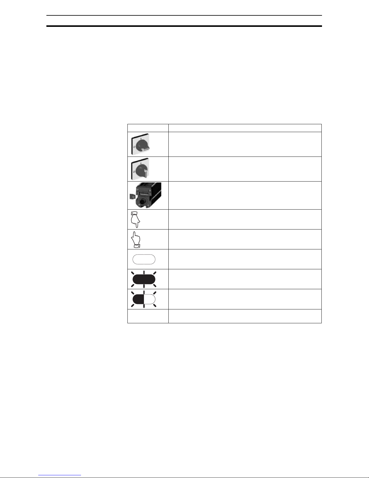
2-12 Definition of symbols
The following symbols are used to illustrate user operations in the F3S-TGRCL system.
SYMBOL MEANING
Turn OFF the entire F3S-TGR-CL system by removing the power
supply.
Turn ON the entire F3S-TGR-CL system by activating power
supply.
Set the selector switches accordingly
Press the related pushbutton/command (change from its normal
status)
Release the related pushbutton/command (return to its normal status)
Diagnosis LED off
Diagnosis LED on
Diagnosis LED blinking
Important information
Page 15

1
SECTION 1
Important safety warnings
!WARNING Read and understand this section prior to installing an F3S-TGR-CL system.
A F3S-TGR-CL system is a general purpose sensing device designed to
guard personnel working around moving machinery.
Whether a specific machine application and F3S-TGR-CL system installation
complies with safety regulations depends on the proper application, installation, maintenance and operation of the F3S-TGR-CL system. These items are
the responsibility of the purchaser, installer and employer.
The employer is responsible for the selection and training of personnel to
properly install, operate and maintain the machine and its safeguarding systems. A F3S-TGR-CL system should only be installed verified and maintained
by a qualified person. A qualified person is defined as "an individual who
understands, is trained on, and demonstrates competence with the construction, operation or maintenance of the machinery and the hazards involved."
To use the F3S-TGR-CL system the following requirements must be met:
• The national/international rules and regulations apply to the installation,
use and periodic technical inspections of the safety light curtain, in particular:
• Machine Directive (2006/42/EC)
• Equipment Usage Directive (89/655/EC)
• The work safety regulations/safety rules
• Other relevant health and safety regulations
• Observe the instructions in this manual regarding test regulations (e.g. on
use, mounting, installation or integration into the existing machine control
system) carefully.
• The tests must be carried out by specialist personnel or specially qualified
and authorized personnel and must be recorded and documented to
ensure that the tests can be reconstructed and retraced at any time.
• Check the effectiveness of the protective device after every change
because a change may degrade the safety function.
• The operating instructions must be made available to the operator of the
machine where the F3S-TGR-CL system is installed.
• The machine operator is to be instructed in the use of the device by specialist personnel and must be instructed to read the operating instructions.
• The guarded machine must not present a hazard from flying parts.
• The guarded machine must have a consistent stopping time and adequate control mechanisms.
• Additional guarding may be required for access to dangerous areas not
covered by the F3S-TGR-CL system.
Protection of the environment
This product has been designed to minimize environmental impact. For this
reason please note that disposal of irreparable/unserviceable devices has to
be in compliance with your local/national rules and regulations. Please contact your local OMRON sales representative for assistance.
Page 16

2
SECTION 2
Product features and indicators
2-1 F3S-TGR-CL feature list
The F3S-TGR-CL safety light curtain family is available in two versions. These
versions are identified as the F3S-TGR-CL_A and F3S-TGR-CL_B versions.
Configuration of the safety light curtains can be changed through selector
switches located under an access cover.
F3S-TGR-CL series feature comparison:
2-2 LED indicators
LED indicators are located in the connector end caps to show the status of the
F3S-TGR-CL system.
2-2-1 LED indicators on transmitter
2-2-2 LED indicators on receiver
Feature F3S-TGR-CL_B F3S-TGR-CL_A
Scan Code for Cross-Talk-Mitigation X X
EDM External Device Monitoring X X
Adjustable Mounting Brackets and T-Slots X X
Two PNP safety outputs X X
Range Selection X X
External test initiation X X
Integrated muting function X
Pre-reset operation X
Disposition of indicator Name of indicator Colour
POWER Green
STATUS 1 Yellow
RANGE Green
Not used Red
STATUS 2 Yellow
Disposition of indicator Name of indicator Colour
POWER Green
STATUS Yellow
GUARD Green
BREAK Red
INTERLOCK Yellow
POWER
STATUS 1
NEAR/FAR
STATUS 2
TX
POWER
STATUS
GUARD
BREAK
INTERLOCK
RX
Page 17

3
SECTION 3
System Operation
The F3S-TGR-CL system is a microprocessor-controlled, infrared, transmitted-beam safety light curtain. The system consists of a receiver assembly and
a transmitter assembly. The receiver and transmitter assemblies are not physically interconnected.
It complies with a Type 2 or Type 4 according to EN/IEC 61496 and up to PLc
or PLe according to EN ISO 13849-1 (2008), depending on the model .
A F3S-TGR-CL system is used where personnel protection is required, typical
applications include packaging machines, front- or back side protection of
presses and textile machinery.
3-1 Operating States
The operating condition of a F3S-TGR-CL system is described in terms of
states. The following operating states exist for a F3S-TGR-CL system.
3-1-1 Machine Run
The two receiver safety outputs are in the ON state, the green GUARD indicator is lit. The protected machine is allowed to operate. Pressing and releasing
the restart button has no effect.
3-1-2 Machine Stop
The two receiver safety outputs are in the OFF state the red BREAK indicator
is lit. The protected machine is not allowed to operate.
3-1-3 Interlock
The two receiver safety outputs are in the OFF state, the red BREAK indicator
and yellow INTERLOCK indicator are lit. The INTERLOCK state does not
allow the protected machine to operate until the detection zone is clear of
obstructions and the restart button is pressed and released.
3-1-4 Error
The two receiver safety outputs are in the OFF state, an error code is shown
via the blinking indicators. The error state does not allow the protected
machine to operate. The primary difference between ERROR and INTERLOCK is that the F3S-TGR-CL system will remain in the error state until the
error is corrected, and then applying a power cycling or an external restart
button press and release.
Page 18

4
Operating Modes Section 3-2
3-2 Operating Modes
System operating modes determine the start-up and operating behavior of a
F3S-TGR-CL system. Operating modes definitions rely on the operating
states presented above. Operating mode selection may be performed via the
configuration switches on the F3S-TGR-CL transmitter and receiver.
Note If internal errors are detected by the system during power-up or operation, it
will enter the Error state with its safety outputs in the OFF state.
3-2-1 Automatic start
The F3S-TGR-CL will power-up with its safety outputs OFF, and if the detection zone is not obstructed, enters the MACHINE RUN state. In this state,
when an object is sensed entering the detection zone, the F3S-TGR-CL system will change from MACHINE RUN to MACHINE STOP and remain in this
state until the obstruction is removed. Once the detection zone is clear, the
F3S-TGR-CL system will automatically change from MACHINE STOP to
MACHINE RUN.
3-2-2 Start/Restart Interlock
!WARNING The TEST/RESTART button must be located so that the operator can see the
protected area when restarting, testing or overriding.
The F3S-TGR-CL will power-up with its safety outputs off and enter the
INTERLOCK state if the detection zone is clear. To initially enter the
MACHINE RUN state the operator must press and release the Restart button.
Once in the MACHINE RUN state, when an object is sensed entering the
detection zone, the system will change to the MACHINE STOP state. When
the detection zone is cleared, the system will not automatically change to
MACHINE RUN but enter the INTERLOCK state instead. The operator must
always press and release the Restart button to enter MACHINE RUN. If the
detection zone is not clear the Restart button will have no effect.
3-2-3 Pre-reset operation
The Pre-Reset function is used in installations where operators inside the
dangerous zone can be hidden by parts of the installation. A second Reset
pushbutton (Pre-reset) is added inside the dangerous zone. Before leaving
the dangerous zone, the operator has to operate the Pre-reset pushbutton.
This enables the Restart pushbutton outside the dangerous zone.
The F3S-TGR-CL will power-up with its safety outputs off and enter the
INTERLOCK state if the detection zone is clear. To initially enter the
MACHINE RUN state the operator must press and release the Pre-reset and
Restart button. Once in the MACHINE RUN state, when an object is sensed
entering the detection zone, the system will change to the MACHINE STOP
state. When the detection zone is cleared, the system will not automatically
change to MACHINE RUN but enter the INTERLOCK state instead. The operator must always press and release the Pre-reset and the Restart button in
this sequence to enter MACHINE RUN. If the detection zone is not clear the
Pre-reset or Restart button will have no effect.
Page 19

5
SECTION 4
Detection options
4-1 Optical synchronization
The synchronization between the F3S-TGR-CL system transmitter and
receiver is optical synchronization. To establish synchronization the system
needs to have the beam opposite side of the connector end cap clear. If this
beam is blocked, the system will enter a MACHINE STOP state.
Page 20
6
SECTION 5
Diagnostic and Test Features
5-1 LED indicators
All F3S-TGR-CL systems have visible LED on the receiver element to show
the proper alignment of the system. These LEDs are used during alignment
process and they are not part of the safety critical system. A failure in one of
these indicators will not cause an alarm condition and the system will continue
to operate.
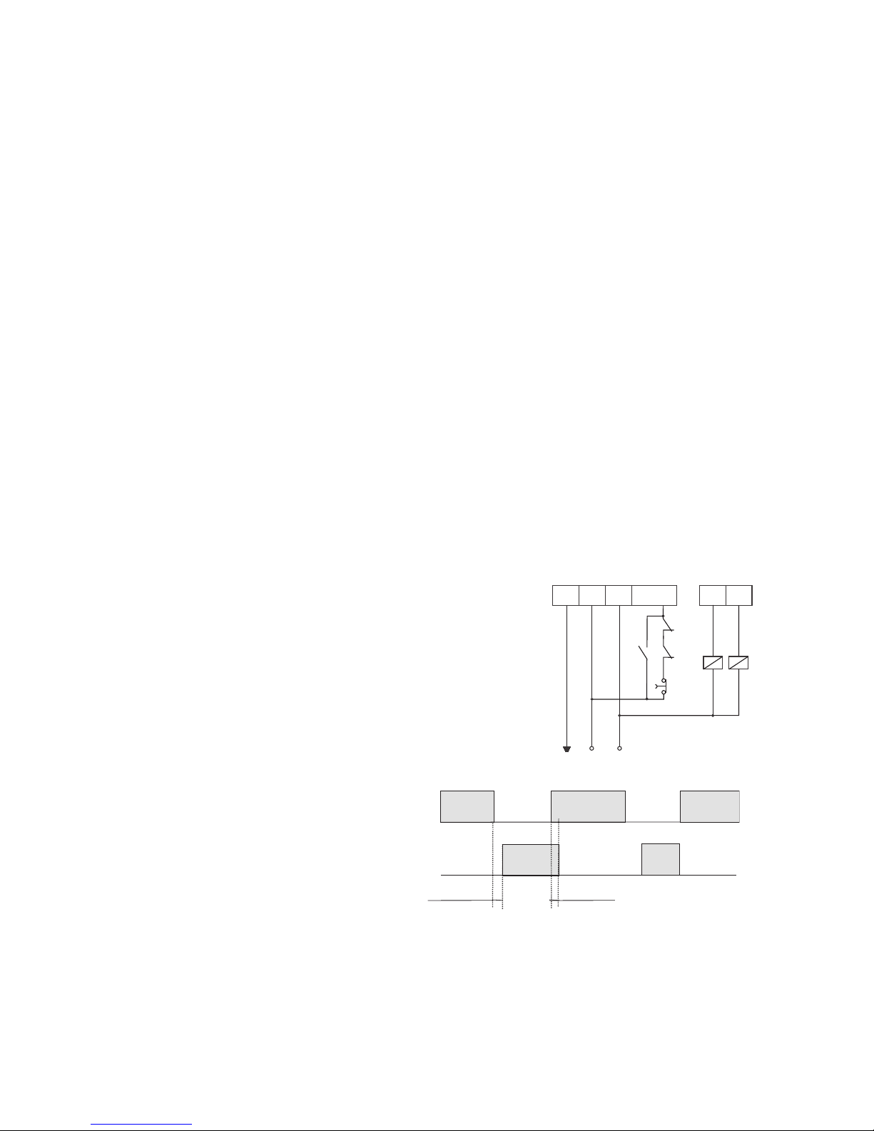
5-2 External Device Monitoring (EDM)
EDM is an important safety function. It monitors the F3S-TGR-CL system
interface to the guarded machine, checks to ensure that the control elements
are responding correctly to the light curtain and detects any inconsistency
between the two external control devices. This is necessary to detect a malfunction within the interface which prevents a stop signal from reaching the
machine controller. The connection for the EDM is made at the receiver. On
power-up, the F3S-TGR-CL system looks for a closed to +24VDC condition. If
this is found, it will enter a state consistent with the selected operating mode.
When the F3S-TGR-CL system enables its safety outputs, it monitors the
external devices for a closed to open transition. This transition must occur
within 300ms or the F3S-TGR-CL system will then enter an alarm state. Additionally, if the EDM connections are incorrectly wired, the system will enter an
alarm state.
The EDM function can be activated and
deactivated using the selector switches
on the receiver unit (both DIP Switch
Nr.6).
Wiring diagram:
K1 and K2 are standard contactors,
KM1 and KM2 are NC contacts (forcibly
guided) of K1 and K2.
Timing diagram:
24 Vdc
Shield
OUT 1
OUT 2
TEST
RESTAR T
0 Vdc
K1
KM2KM1
K2
RECEIVER
BROWN
WHITEBLUE GRAY
PINK
SCH.
ON
OFF
+24
0v
OSSD
Signal on
White cable
< 0.3sec
Not checked
Page 21
7
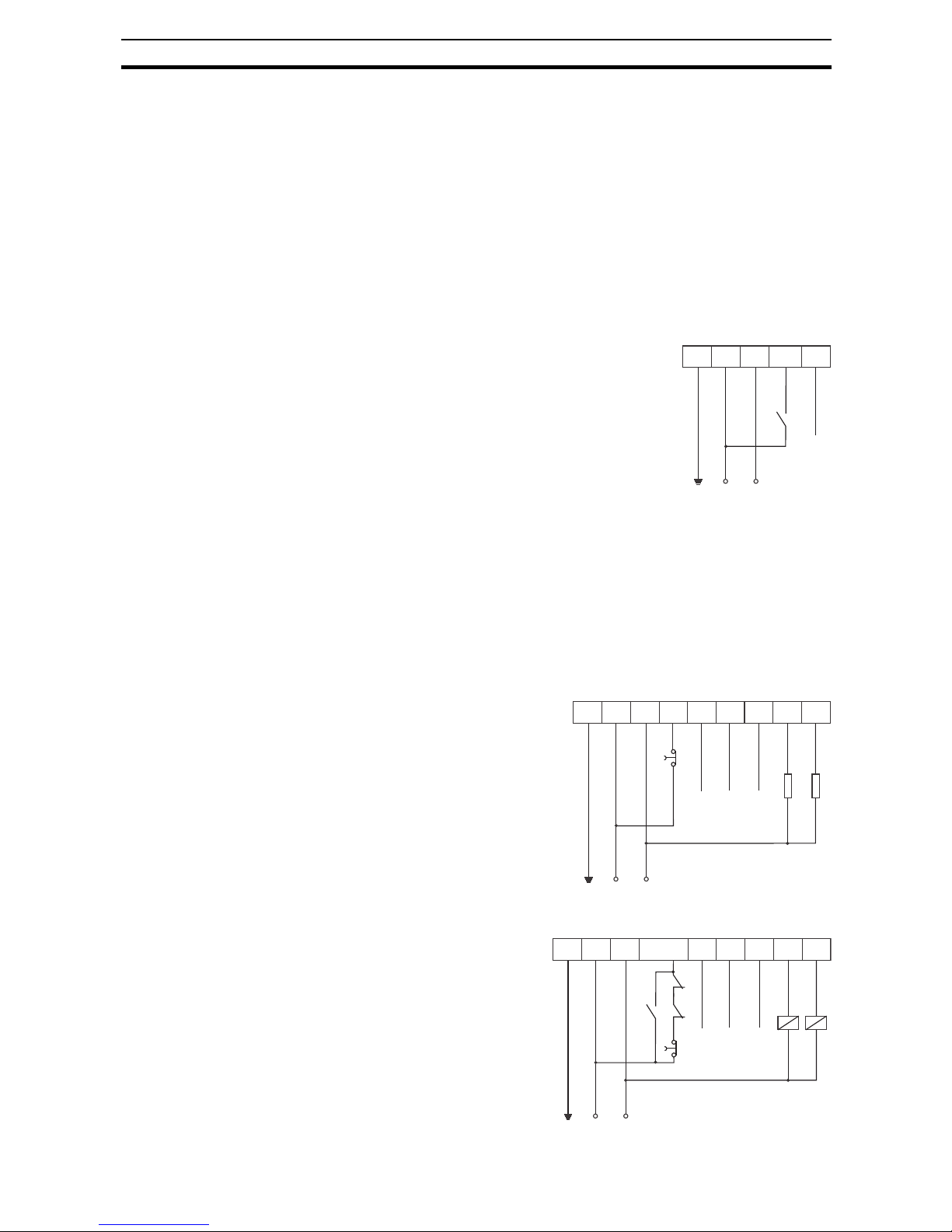
External test function Section 5-3
5-3 External test function
Some category 4 applications require that the machine guarding system is
tested by the machine controller during a non-hazardous portion of the
machine cycle to verify that the guarding system is functioning properly. In
category 2 the test should be done by machine operator. F3S-TGR-CL system offers a test function on the transmitter or on the receiver element.
Transmitter:
The test function is provided by placing a normally-open switch on the test
input of the transmitter. If the transmitter recognizes a +24VDC signal, a beam
block state will be simulated on the transmitter and the receiver will enter the
MACHINE STOP state.
Wiring diagram:
Receiver:
The test function is provided by placing a switch on the test/restart input of the
receiver.
If the outputs are in OFF state, the system will run a start-up-test and if the
beams are free, it will change to MACHINE RUN state.
If the outputs are in ON state and the test/restart input is activated for more
than 2sec., the system will enter MACHINE STOP state and run a start-uptest (for Category 2 control systems).
Wiring diagram with EDM
disabled:
Wiring with EDM enabled:
24 Vdc
Shield
TEST
0 Vdc
N.C.
TRANSMITTER
BROWN
BLUE WHITE BLACKSCH.
24 Vdc
Shield
OUT 1
OUT 2
TEST/RESTART
0 Vdc
N.C.
N.C.
N.C.
RECEIVER
BROWN
BLUE WHITE GREEN
YELLOW
RED
GRAY
PINK
SCH.
24 Vdc
Shield
OUT 1
OUT 2
TEST
RESTAR T
0 Vdc
N.C.
N.C.
N.C.
K1
KM2KM1
K2
RECEIVER
BROWN
BLUE WHITE GREEN
YELLOW
RED
GRAY
PINK
SCH.
Page 22
8
Range selection Section 5-4
5-4 Range selection
The F3S-TGR-CL system offers operating range selection. Please refer to the
detailed technical data in the list of models. This function is useful when there
are many light curtains operating within a small space and the possibility of
cross-talk is likely.
5-5 Start/Restart Input
The characteristic of the Start/Restart Input is shown in the following schematic:
5-6 Alignment support
Alignment of the F3S-TGR-CL system is supported by the alignment support
mode.
F3S-TGR-CL
Restart
N.C.
+24 VDC
1 2 3 4
Leave disconnected
Mechanically adjust sensors to reach the alignment if necessary.
5 6 7 8
When alignment Ok:
POWER
STATUS
GUARD
INTERLOCK
Reconnect
Page 23
9
SECTION 6
Setting F3S-TGR-CL features
!WARNING Make sure that foreign objects such as water, oil, or dust do not enter the
inside of the F3S-TGR-CL system while the cover for the selector switches is
open.
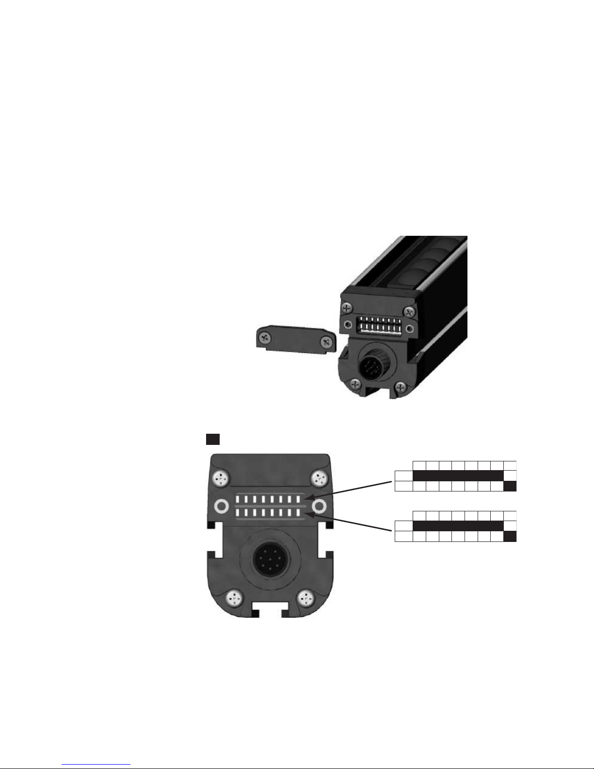
6-1 Access to the selector switches
The switches are located behind a cover on both the transmitter and receiver.
The covers are opened by loosening two retaining screws (see illustration
below).
Disconnect the power supply before changing the switch settings.
6-1-1 Selector switch setting
Note Make sure to set always switches in both banks to the same position
(except switch 7 on the receiver).
1 2 3 4 5 6 7 8
OFF
ON
= dip-switch level position (Factory default setting)
1 2 3 4 5 6 7 8
OFF
ON
OFF is the upper position and
ON is the lower position.
Page 24

10
Access to the selector switches Section 6-1
6-1-2 Transmitter selector switch settings
Selector switches 5 - 8 are not used in the transmitter.
Please refer to the table below for the range setting:
Switch Position Setting Function Default
1 OFF RANGE SETTING –
ON SHORT RANGE X
2 OFF RANGE SETTING – X
ON LONG RANGE
3 OFF CODE SETTING NO CODING X
ON CODING
4 OFF CODE SELECTION CODE A
ON CODE B
SW-1 SW-2 Range selected
OFF OFF NOT ALLOWED
OFF ON LONG RANGE
ON OFF SHORT RANGE
ON ON NOT ALLOWED
Page 25

11
Access to the selector switches Section 6-1
6-1-3 Receiver selector switch setting
Firmware 1.2.5
Note Factory Settings:
RX: All OFF except both DIP switch 8
TX: All OFF except both DIP switch 1
Switch Status Function
8 OFF Manual reset Single break if SB/DB selected
ON Automatic reset Double break if SB/DB selected
7 OFF Refer to CODING section for further information
ON
6 OFF EDM function disabled
ON EDM function enabled
5 + 4
1
1. Selector switches 4 and 5 are operational if a muting indicator is connected or both are set to the ON position.
4 5 MUTING and SPECIAL FUNCTIONS
OFF OFF MUTING T
OFF ON MUTING L
ON OFF MUTING X
ON ON SPECIAL FUNCTION WITH Switches 1, 2 and 3
MUTING MAPS when MUTING T, L or X are selected on switches 4 and 5
2
2. Selector switches 1, 2 and 3 are operational if a muting function is set and a muting indicator is connected.
3 + 2 + 1 1 2 3
OFF OFF OFF Muting active over all light curtain
OFF OFF ON Muting active on module 1,2,3 and 4
OFF ON OFF Muting active on module 1,2 and 3
OFF ON ON Muting active on module 1 and 2
ON OFF OFF Muting active on module 1
ON OFF ON Muting active on module 2
ON ON OFF Muting active on module 3
ON ON ON Muting active on module 4
Special functions selection when switches 4 and 5 are both ON
3
3. Selector switches 1, 2 and 3 are operational if selector switches 4 and 5 are in ON position.
3 + 2 + 1 1 2 3
OFF OFF OFF Not supported
OFF OFF ON
OFF ON OFF
OFF ON ON
ON OFF OFF
ON OFF ON
ON ON OFF Pre-Reset mode
ON ON ON Not supported
Page 26

12
Selecting External Device Monitoring (EDM) Section 6-2
Firmware 1.3.6
6-2 Selecting External Device Monitoring (EDM)
EDM is activated by setting position 6 of Switches A and B located on the
receiver. Any mismatch between the settings of Switches A and B will result in
an alarm condition.
Switch Status Function
8 OFF Manual reset
ON Automatic reset
7 OFF master
lower bank
No codification (dip 7 slave useless)
ON master
lower bank
Codification available by dip 7 slave
OFF slave
upper bank
CODE A
ON slave
upper bank
CODE B
6 OFF EDM function disabled
ON EDM function enabled
5 + 4
1
1. Selector switches 4 and 5 are operational if a muting indicator is connected or both are set to the ON position
4 5 MUTING and SPECIAL FUNCTIONS
OFF OFF MUTING T + timeout + 0,2s deactivation
OFF ON MUTING L + timeout + 0,2s deactivation
ON OFF MUTING X + timeout + 0,2s deactivation
ON ON SPECIAL FUNCTION WITH Switches 1, 2 and 3
MUTING MAPS when MUTING T, L or X are selected on switches 4 and 5
2
2. Selector switches 1, 2 and 3 are operational if a muting function is set and a muting indicator is connected.
3 + 2 + 1 1 2 3
OFF OFF OFF Muting active over all light curtain
OFF OFF ON Muting active on module 1,2,3 and 4
OFF ON OFF Muting active on module 1,2 and 3
OFF ON ON Muting active on module 1 and 2
ON OFF OFF Muting active on module 1
ON OFF ON Muting active on module 2
ON ON OFF Muting active on module 3
ON ON ON Muting active on module 4
Pre-reset selection or Total muting timing selection when dips 4-5 are both ON
3
3. Selector switches 1, 2 and 3 are operational if selector switches 4 and 5 are in ON position
3 + 2 + 1 1 2 3
OFF OFF OFF Muting type T + timeout + 1s deactivation
OFF OFF ON Muting type L + timeout + 1s deactivation
OFF ON OFF Muting type X + timeout + 1s deactivation
OFF ON ON Muting type T + no timeout + 1s deactivation
ON OFF OFF Muting type L + no timeout + 1s deactivation
ON OFF ON Muting type X + no timeout + 1s deactivation
ON ON OFF Pre-Reset mode
ON ON ON Muting type X compatible with old wiring and timing
Page 27

13
Range setting Section 6-3
6-3 Range setting
Operating range is set using switches 1 and 2 on the transmitter. Please refer
to the table for valid switch position settings.
!WARNING Never use a long range light curtain for distances under the operating range.
Failure to do so may cause serious injury.
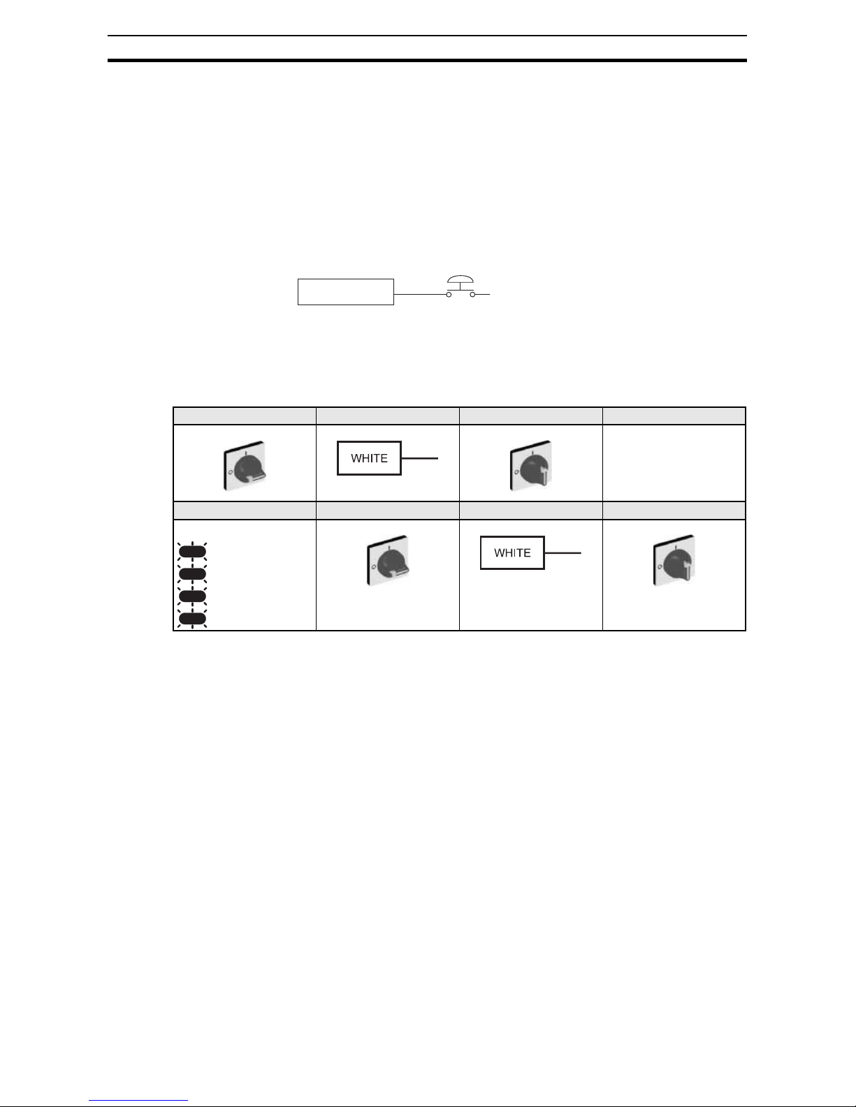
6-4 Selecting Scan Codes
The F3S-TGR-CL receiver and transmitter offer scan code selection to minimize cross talk.
Note Both receiver and transmitter must be set to the same code.
Example:
Sequence to activate Scan Codes:
1 2 3
TX
1 -> ON SHORT RANGE SELECTION
2 ->OFF
1 -> OFF LONG RANGE SELECTION
2 -> ON
4 5
RANGE: LONG RANGE
RANGE: SHORT RANGE
12 3 4 5
TX/RX
Connect white wire
of TX to pink wire of
RX SLC
all LEDs 1 time =
CODE A
all LEDs 2 times =
CODE B
Scan Code A
Scan Code B
Page 28

14
Selecting Scan Codes Section 6-4
Wiring diagram when Scan codes are used:
Note Only available at Active-Active units.
Note Please make sure that the total cable length between the two units is not
longer than 100 m when coding is used .
Transmitter Scan Code setting, using switches 3 and 4:
Receiver Scan Code setting, using switch 7:
Note With Active/Passive systems just refer to the Receiver site.
24 Vdc
Shield
PIN 2 7 1 3 4 8 5 6
OUT 1
OUT 2
RL 250mA max
RL 250mA max
TEST/RESTART
0 Vdc
N.C.
N.C.
N.C.
RECEIVER
BROWN
BLUE WHITE GREEN
YELLOW
RED
GRAY
PINK
SCH.
24 Vdc
Shield
PIN 1 3 2 4
0 Vdc
N.C.
TRANSMITTER
BROWN
BLUE WHITE BLACKSCH.
Note please refer to 6-1-3 Receiver
selector switch setting
SWITCH 3
OFF No code
(exclusion of dip 4)
ON CODE ON
SWITCH 4
OFF CODE A
ON CODE B
UPPER SWITCH BANK 7
OFF CODE A
ON CODE B
LOWER SWITCH BANK 7
OFF No code
(exclusion of dip 7 on upper bank)
ON Code
Page 29

15
SECTION 7
Outputs
7-1 Safety Outputs (OSSDs)
Note This product is designed for use on a 24 VDC, negative ground (protective
earth) electrical system only. Never connect the F3S-TGR-CL system to a
positive ground (protective earth) system. With a positive ground (protective
earth) wiring scheme, certain simultaneous shorts of both safety outputs may
not be detected and the guarded machine may not stop, resulting in severe
operator injury.
The F3S-TGR-CL system receiver supplies two independent PNP type safety
outputs to provide run/stop signals to the guarded machine. In the MACHINE
RUN state, the safety outputs are electrically conducting and source 250mA
of current at 24 VDC. In the MACHINE STOP state, the outputs are not electrically conducting.
For loads higher than 250 mA for each OSSD or AC current, please use external safety relay units or forcibly guided safety relays and enable the EDM
function.
7-2 Safety Outputs (OSSDs) waveform
Normal conditions MACHINE RUN state
F3S-TGR-CL in MACHINE RUN state, no coding selected
t
1
: Test pulse 300 µs
t
2
: Test interval > Response time x 0.33
t
3
: Repetition > Response time x 0.66
F3S-TGR-CL in MACHINE RUN state, coding selected
t
1
: Test pulse 300 µs
t
2
: Test interval > Response time x 0.33
t
3
: Repetition > Response time x 0.16
OSSD1
OSSD2
t
1
t
2
t
3
Page 30

16
Safety Outputs (OSSDs) waveform Section 7-2
F3S-TGR-CL in MACHINE STOP state, coding selected
t
1
Test pulse 70 µs
t
2
Test interval 33 ms
OSSD1
OSSD2
t
1
t
2
Page 31

17
SECTION 8
Safe Mounting Distance
!WARNING Never install an F3S-TGR-CL system without
regard to the safety distance. If the F3S-TGRCL system is mounted too close to the point of
operation hazard, the machine may not stop in
time to prevent an operator injury.
An F3S-TGR-CL system must be mounted far enough from the machine danger zone so the machine will stop before a hand or other body part reaches
the hazardous area. This distance is called the safety distance. It is a calculated number based on a formula.
The safety distance "S" is the minimum safe distance between the safety light
curtain and the point of operation (pinch point).
Calculation of the safety distance "S" is based on the European standard
EN ISO 13855: 2010 and applies to safety light curtains that are used in
industrial environments.
!WARNING F3S-TGR-CL body protection systems are not suitable for protection of dan-
ger areas (horizontal installation).
Light Curtain
S
S
Direction of
approach
Page 32

18
Safety distance for safeguarding danger points Section 8-1
8-1 Safety distance for safeguarding danger points
!WARNING Additional countermeasures may be necessary to prevent access to the dan-
gerous area from above, below, the sides or the rear of the machine.
Formula according to EN ISO 13855:2010:
S = (K x T) + C
Where S = minimum distance in millimeters from the danger zone to the
detection point, line, plane or zone. If the result of the calculation is less than 100 mm, a distance of at least 100 mm must
still be maintained.
K = Approach speed in mm/s. K can be calculated as 1600 mm/s.
T = the overall system stopping performance in seconds
T = t
1
+ t2 + t
3
t1 = response time of the safety light curtain in seconds,
given in the table in SECTION 14.
t
2
= response time of the safety interface tsi, if any.
t
3
= maximum stopping time of the machine tm in
seconds.
Please refer to the technical information of the safety
Interface and the machine for the response time and stopping
time details.
C = constant for body protection = 850 mm
S = (1600 mm/s x T) + 850 mm
S
Direction of
approach
Page 33

19
Safety distance and beam heights in access guarding Section 8-2
8-2 Safety distance and beam heights in access guarding
!WARNING Additional countermeasures may be necessary to prevent access to the dan-
gerous area from above, below, the sides or the rear of the machine.
According to EN ISO 13855: 2010:
L = the bottom opical beam must not have a height above the ref-
erence plane higher than 400 mm.
H = the top optical beam must not be below 900 mm above the
reference plane.
The height of the protective field "H" above the reference plane and the resolution "d" of the F3S-TGR-CL system have the following relationship:
S = (K x T) + C
For K and T please refer to the previous chapter
C = 850 mm
S = (1600 mm/s x T) + 850 mm
H
S
L
Direction of
approach
Number of
beams
Model number Height of the beams above the
reference plane
2 F3S-TGR-CL-K2C-500
F3S-TGR-CL-K2-500
F3S-TGR-CL-K2-500-LD
400mm, 900mm
3 F3S-TGR-CL-K3C-800
F3S-TGR-CL-K3-800
F3S-TGR-CL-K3-800-LD
300mm, 700mm, 1100mm
4 F3S-TGR-CL-K4C-900
F3S-TGR-CL-K4-900
F3S-TGR-CL-K4-900-LD
300 mm, 600 mm, 900 mm,
1200 mm
4 F3S-TGR-CL-K4C-1200
F3S-TGR-CL-K4-1200
F3S-TGR-CL-K4-1200-LD
300mm, 700mm, 1100mm,
1500 mm
Page 34

20
SECTION 9
Installation
!WARNING Install the sensor system so that it is not affected by reflective surfaces. Fail-
ure to do so may hinder detection, resulting in serious injury.
9-1 Reflective surface interference
A reflective surface adjacent to the detection zone can deflect the optical
beam and may cause an obstruction in the zone not to be detected. The
reflective surface may be part of the machine, mechanical guard or workpiece. Therefore, a minimum distance (d) must exist between the reflective
object and the center line of the detection zone. The Test procedure ("Test
procedure log" on page 65) must be used to test for this condition.
In this picture, the interruption is clearly detected. The reflective object is outside of the beam angle.
Operating range R: is the effective working distance of the F3S-TGR-CL sys-
tem, from the transmitter to the receiver.
EAA: is the effective aperture angle of the Safety Sensor.
it is ±2,5° for F3S-TGR-CL4...
it is ±5° for F3S-TGR-CL2...
distance d: is the minimum distance to a reflective surface.
This distance must be bigger than:
dmin F3S-TGR-CL4 = tan(2,5°)R
dmin F3S-TGR-CL2 = tan(5°)R
Be aware that reflective surface interference may also appear above and
below the sensing field.
Operating range R
Tr ansmitter Receiver
Interruption
Approach direction
Reflective surface
EAA
d = distance to
reflective surface
Page 35

21
Cross Talk Mitigation Section 9-2
The following graphs show the minimum distance d for a operating range R of
up to 20 m:
9-2 Cross Talk Mitigation
To mitigate interference from other light curtains, the F3S-TGR-CL system
has two possible scan codes, A and B. The transmitter and receiver units
must be set to the same scan code for the receiver to enter the MACHINE
RUN state.
-2
-1,5
-1
-0,5
0
0,5
1
1,5
2
0,1 0,2 0,5 1 2 3 45678 910111213 14 15 16 17 18 19 20
Operating range R [m]
Minimum distance d [m]
Type 2
-1
-0,8
-0,6
-0,4
-0,2
0
0,2
0,4
0,6
0,8
1
0,1 0, 2 0,5 1 2 3 45678 910111213 14 15 16 17 18 19 20
Operating range R [m]
Minimum distance d [m]
Type 4
Scan Code A
Scan Code B
Page 36

22
General mounting considerations Section 9-3
9-3 General mounting considerations
9-3-1 Additional Guarding
Areas of access to the point of hazardous operation not guarded by the F3STGR-CL system must be protected by suitable means such as a fixed barrier
guard, an interlocked guard or a safety mat system.
9-3-2 Mechanical installation
The F3S-TGR-CL system is mechanically installed by using the T-slots on the
two sides or the back-side of the housing.
Use the movable bolts, washers, growers and nuts to fix the mounting brackets as shown in the picture
Note Shipment contains different quantity of brackets, depending on the length of
the SLC. Longer SLC contains a higher number of brackets, following the rule
of every 400 mm one bracket.
9-3-3 Additional mounting rigidity
It is recommended that the distance between the mounting brackets is
400 mm or less for optimum performance of the F3S-TGR-CL system.
ID Description
1 movable M6 bolt
2 fixing braket
3 M6 washer
4 M6 Grower
5M6 nut
Page 37

23
General mounting considerations Section 9-3
9-3-4 Mechanical mounting
Physical alignment of the transmitter and receiver is easiest when the system
is in the automatic start operating mode with Blanking inactive. The units
should be in the same plane and at equal height.
Transmitter and receiver unit are mounted parallel to each other and orthogonal in respect to the detection zone between transmitter and receiver. It is
required that the connectors are oriented in the same direction.
Below pictures show GOOD and NOT GOOD installations:
GOOD
NOT GOOD NOT GOOD NOT GOOD
Page 38

24
General mounting considerations Section 9-3
9-3-5 Installation of multiple systems
When two or more F3S-TGR-CL systems with the same scan code are
mounted in close proximity and in alignment with each other, precautions
should be taken to avoid one system interfering with another. This can be corrected by mounting the transmitters and receivers back-to-back or stacked.
The scan code feature of the F3S-TGR-CL system allows for placement of
systems in close proximity and in line with each other. The distinctive coding
of the beams provide for unique operation of a system while in view of another
system with a different scan code. Two unique codes are available on the
F3S-TGR-CL.
9-3-6 Detection Zone (indication on the Front Label)
The system detection zone is delineated by the inside edge of the transmitter
and receiver endcaps and indicated by marks on the transmitter and receiver
unit (Except on Active - Passiv sytems the label is only on the Receiver
(Active) unit.). The area outside these marks is not protected. Position the
system so that it is only possible to access the danger point through the
detection zone.
9-3-7 Requirements for Perimeter Guarding
In perimeter guarding applications the F3S-TGR-CL system detection zone is
placed around the outside perimeter of a guarded machine. This placement
leaves space for personnel to stand between the detection zone and the hazardous machine.
Transmitter
Receiver
Transmitter
Receiver
Machine 1 Machine 2
PREFERRED INSTALLATION
Code A
Code A
Machine 1
Transmitter
Transmitter
Receiver
Machine 2
Receiver
NOT RECOMMENDED INSTALLATION
Code A
Code A
Machine 1
Transmitter
Transmitter
Receiver
Machine 2
Receiver
Code A
Code B
rewoP
sutatS
drauG
kaerB
kcolretnI
EDM
Operating Mode
Muting T
Muting X
Muting L
Enable
Manual reset
Disable
Automatic reset
4=OFF
4=ON
4=OFF
6=OFF
8=OFF
5=OFF
5=OFF
5=ON
6=ON
8=ON
4=OFF
4=ON
4=OFF
6=OFF
8=OFF
5=OFF
5=OFF
5=ON
6=ON
8=ON
SWA SWB
SWB
SW
A
SW
B
ON
OFF
ON
OFF
For furtherinformation please refer
to Installation and Operation manual
rewoP
1sutatS
raF\raeN
2sutatS
Code Settings
Code Selection
Coding
Code A
3=ON
4=OFF
3=OFF
4=ON
No Coding
Code B
SWA
For furtherinformation please refer
to Installation and Operation manual
Short Range
Long Range
1=ON
1=OFF
2=OFF
2=ON
1=ON
1=OFF
2=OFF
2=ON
4=OFF
4=ON
3=ON
3=OFF
SWB
SW
A
SW
B
Start of Detection zone
Start of Detection zone
Operating Mode
ON
OFF
ON
OFF
Label RX Label TX
Page 39

25
General mounting considerations Section 9-3
In this case, the guarded machine must only be restarted using a switch
located outside and with a full view of the area of hazardous motion. Operation of the F3S-TGR-CL system In the Start/Restart Interlock operating mode
is suitable for perimeter guarding.
Page 40

26
SECTION 10
Connection to the Machine control circuit
!WARNING This product is designed for use on a 24 VDC, negative ground (protective
earth) electrical system only. Never connect the F3S-TGR-CL system to a
positive ground (protective earth) system. With a positive ground (protective
earth) wiring scheme, certain simultaneous shorts of both safety outputs may
not be detected and the guarded machine may not stop, resulting in severe
operator injury.
!WARNING Never use only a single safety output to control the machine. Should this sin-
gle output fail, the machine may not stop, resulting in severe operator injury.
The machine must be connected using both safety outputs.
10-1 Input Power Requirements
The system operates directly from 24 VDC ±20%. Power to the system must
come from a power supply which meets the requirements of EN/IEC60204-1
and EN/IEC 61496-1.
The power supply must guarantee safe insulation from the mains voltage in
accordance with IEC60742 (Protective class III, double insulation) and be
able to cover a drop of supply voltage of at least 20 ms. OMRON offers suitable power supplies. Transmitters and receivers must be supplied from a
shared power supply and must be fused against over current. An external fuse
of 1A must be used.
10-2 Cables
The primary cables for the F3S-TGR-CL system are industry standard
shielded cables with an M12 female connector. The receiver and transmitter
incorporate a M12 male connector.
We recommend to use the F39-TGR-CVL cables to connect the F3S-TGR-CL
system to the machine control system.
Note For further information please refer to 14-5-5 Cables (page 59)
Page 41

27
Basic wiring scheme Section 10-3
10-3 Basic wiring scheme
Transmitter
Receiver
Refer to the sections Muting and override (page 30) and Pre-reset function
(page 39) for further information.
21
5
3 4
24 Vdc
Shield
PIN 1 3 2 4
TEST(optional)
0 Vdc
N.C.
TRANSMITTER
BROWN
BLUE WHITE BLACKSCH.
Pin No. Signal Name Wire Colour
2 1 Input Power +24V Brown
1 2 Test Input White
4 3 Input Power GND Blue
3 4 Not used Black
5 5 Not used Green
1
3
2
8
6
5
4
7
24 Vdc
Shield
PIN 2 7 1 3 4 8 5 6
OUT 1
OUT 2
RL 250mA max
RL 250mA max
TEST/RESTART
0 Vdc
N.C.
N.C.
N.C.
RECEIVER
BROWN
BLUE WHITE GREEN
YELLOW
RED
GRAY
PINK
SCH.
Pin No. Signal Name Wire Colour
1 Test/Restart White
2 Input Power +24V Brown
3 Muting A Green
4 Muting B Yellow
5 Output signal OSSD1 Gray
6 Output signal OSSD 2 Pink
7 Input Power GND Blue
8 Muting lamp connection LMS Red
Note For Active - Passive
systems please keep in
mind there is no wiring on
Transmitter (Passiv) side.
Page 42

28
Wiring to two forcibly guided relays Section 10-4
10-4 Wiring to two forcibly guided relays
F3S-TGR-CL is set in manual reset operation mode.
Note For Active - Passive systems please keep in mind there is no wiring on Trans-
mitter (Passiv) side.
Note The achievable safety category or performance level using this circuit
depends on the safety light curtain in use and the correct wiring of the safety
control unit.
Note This circuit can achieve a PL=e acc. ISO 13849-1 if a F3S-TGR-CL-4_ is
used.
Shield
Mut. B (Yellow)
+24 VDC (Brown)
OSSD1 (Gray)
Te st (White)
+24 (Brown)
OSSD2 (Pink)
Te st/restart (White)
0VDC (Blue)
Mut. A (Green)
Mut. Lamp (Red)
Shield
0 VDC (Blue)
R S T
F3S-TGR-CL
11
23
33
4344
34
24
12
01
11
23
33
4344
34
24
12
01
RESTA RT
TEST
M
24Vdc +
-
G7SA-3A1B
G7SA-3A1B
RECEIVERTRANSMITTER
Page 43

29
Connection to a safety relay unit Section 10-5
10-5 Connection to a safety relay unit
F3S-TGR-CL is set in automatic reset mode. G9SB is in manual reset mode.
Note For Active - Passive systems please keep in mind there is no wiring on Trans-
mitter (Passiv) side.
Note The achievable safety category or performance level using this circuit
depends on the safety light curtain in use and the correct wiring of the safety
control unit.
Note This circuit can achieve a PL=e acc. ISO 13849-1 if a F3S-TGR-CL-4_ is
used.
+24 (Brown)
Shield
Shield
OSSD1 (Gray)
OSSD2 (Pink)
0VDC (Blue)
Mut. Lamp (Red)
Mut. B (Yellow)
Mut. A (Green)
Te st/restart (White)
Feedback loop
+24 VDC (Brown)
0 VDC (Blue)
Te st (White)
F3S-TGR-CL
KM1 KM2
RECEIVERTRANSMITTER
K1
K2
A1 T11 T12 T21 T22 T31T3213 233341
42342414A2
G9SB-301-D
CONTROL
CIRCUIT
K1
K2
S1
24Vdc +
M
KM1
KM2
S2
KM1
KM2
Page 44

30
SECTION 11
Control functions
11-1 Muting and override
This function is only available on the F3S-TGR-CL_A - models.
!WARNING The muting and override functions disable the safety functions of the device.
You must ensure safety using other method when these functions are operating.
!WARNING Install muting sensors so that they can distinguish between the object that is
being allowed to pass through the detection zone and a person. If the muting
function is activated by the detection of a person, it may result in serious
injury.
!WARNING Muting lamps (external indicators) that indicate the state of the muting and
override functions must be installed where they are clearly visible to workers
from all the operating positions.
!WARNING Muting related time must be properly configured for its application by a suffi-
ciently trained and qualified person, and the person must have responsibility
for settings.
!WARNING Use independent 2 input devices for muting inputs.
!WARNING You must install F3S-TGR-CL system muting sensor, and physical barrier, and
configure time settings for muting so that an operator should not enter hazardous zone.
!WARNING Install the switch that activates the override in a location that provides a clear
view of the entire hazardous area and where it cannot be activated from within
the hazardous area. Make sure that nobody is in the hazardous area before
activating the override function.
During muting condition, the monitoring of the protective field is suppressed
intentionally for a preset time. It is used in applications, where material goes
into or out of a dangerous zone without stopping the machine, so the Safety
Outputs (OSSDs) of the Safety Sensor System remain in the ON-State during
the muting procedure.
The Muting function can be activated only if the F3S-TGR-CL system is in the
MACHINE RUN state while the muting activation sequence is provided.
Note Modifications for infinity muting starts with Firmeware 1.3.6
Page 45

31
Muting and override Section 11-1
11-1-1 Wiring
Firmware 1.2.5 To control and activate the mut-
ing function, the inputs
•Muting A
•Muting B
• External Muting lamp
connection (LMS)
are used.
11-1-2 Activation and de-activation of the muting function
The muting function is enabled by default for all F3S-TGR-CL-A - models.
11-1-3 External muting lamp requirements
The external muting lamp for muting and muting override must be installed in
a position where it can be clearly seen by the operators. A LED indicator- or
standard bulb-based lamp can be used to indicate muting.
Any failure of the muting lamp or in wiring is recognized by the F3S-TGR-CL
system and will result in an ERROR condition.
11-1-4 Muting input requirements
Muting A and Muting B can be provided by mechanical switches, proximity
sensors or photoelectric switches with a closed contact if an object is
detected.
At least one of the signals must be a hardware signal. It is not allowed to just
control the muting function by software.
Please make sure that the installation of the muting sensors follows the
requirements shown in the next chapters.
11-1-5 Muting modes
The F3S-TGR-CL system offers a set of three muting modes:
• T-muting activation (default)
• L-muting activation
• X-muting activation
RT in the pictures below refers to the response time of the safety sensor (ON
to OFF according to the technical specification in SECTION 14 on page 44).
TM is the time difference between activating Muting sensor A and Muting sensor B.
Please pay attention to the new Firmware 1.3.6. for the modification of the
muting function.
With this new Firmware six new combinations of the DIP switches are avail-
able for body protection guards (please refer to 6-1-3 Receiver selector switch
setting).
24 Vdc
Shield
RL 250mA max
RL 250mA max
OUT 1
OUT 2
Muting A
TEST/RESTART
LMS
Muting B
0 Vdc
RECEIVER
BROWN
BLUE WHITE GREEN
YELLOW
RED
GRAY
PINK
SHIELD
Page 46

32
Muting and override Section 11-1
Modification table for
different muting types:
11-1-5-1 T-activation mode
The T-muting activation mode is the default and standard application for muting. Four muting sensors are used in two pairs (OR function), connected to
the two Muting inputs, Muting A and Muting B.
This muting activation mode allows bi-directional transport of material.
Note • d1 is the distance between the muting sensors. It must be more than
250 mm and needs to be checked additionally in regards to the speed of
the material transport and time limitation in the muting function.
• d2 is the distance between the Muting sensor B and the F3S-TGR-CL sys-
tem. It must be as short as possible. Timing limitations and the speed of the
material transport must be considered additionally.
• d3 is the distance between the two sensors connected to Muting A input.
This distance represents the minimum length of the material to be detected.
Timing requirements and limitations:
• If Muting A is activated, Muting B must be activated within 120sec. to activate the muting function. Otherwise muting function is stopped.
• Muting A and Muting B cannot be activated at the same time. A minimum
time difference equal to the response time of the sensor is mandatory.
• Maximum muting time is 600sec. After this time, muting function is
stopped even if the Muting inputs are still active.
Muting
type
Available values f or each timing
A-B time Timeout deactivation
T 0.03s < t <120 s <600s Or Infinite <0.2s Or <1s
L 0.03s < t <120 s <600s Or infinite <0.2s Or <1s
X 0s < t <4s
With MUT B
logically inverted.
<1700s Or infinite <0.2s Or <1s
GOODS
Mut sen.AMut sen.
B
FENCE
d
d2d1 d2 d1
d
d3
Mut sen.BMut sen.
A
DIRECTIONS
ALLOWED
DANGEROUS
AREA
SAFE
AREA
Page 47

33
Muting and override Section 11-1
• The F3S-TGR-CL allows that Muting A or Muting B drop for a maximum
time of 200ms without stopping the muting function. A time longer than
200ms is detected as a muting stop.
11-1-5-2 L-activation mode
The L-muting activation mode can be used in applications where material is
transported only out of the dangerous area,
Two muting sensors are connected to the two Muting inputs, Muting A and
Muting B.
!WARNING This muting activation mode can only be used in uni-directional transport. Fail-
ure to do so may result in serious injury.
Note • d1 is the distance between the muting sensors. It must be more than
250mm and needs to be checked additionally in regards to the speed of the
material transport and time limitation in the muting function.
• d2 is the distance between the Muting sensor B and the F3S-TGR-CL sys-
tem. It must be as short as possible. Timing limitations and the speed of the
material transport must be considered additionally.
Free
Interrupted
ON
OFF
ON
OFF
ON
OFF
Active
OFF
SLC
OSSD
Muting
Input A
Muting
Input B
Muting
Status
RT < TM < 120 sec < 600s
GOODS
Mut sen.AMut sen.
B
F3S-TGR-CL
FENCE
d
d2d1
DIRECTIONS
ALLOWED
DANGEROUS
AREA
SAFE
AREA
Page 48

34
Muting and override Section 11-1
• d is the distance between the F3S-TGR-CL system and the sensor con-
nected to Muting A input. This distance represents the minimum length of
the material to be detected.
Timing requirements and limitations:
• If Muting A is activated, Muting B must be activated within 120 sec. to
activate the muting function. Otherwise muting function is stopped.
• Muting A and Muting B cannot be activated at the same time. A minimum
time difference equal to the response time of the sensor is mandatory.
• If Muting A and Muting B are activated, the protective field must be
obscured within 120 sec. Otherwise the muting function is stopped.
• Maximum muting time is 600 sec. After this time, muting function is
stopped even if the Muting inputs are still active or the protective field is
still obscured.
• The F3S-TGR-CL allows that Muting A or Muting B drop for a maximum
time of 200 ms without stopping the muting function. A time longer than
200 ms is detected as a muting stop.
• The F3S-TGR-CL allows that the protective field becomes free for a maximum time of 200 ms in Muting condition. If the protective field is free for
more than 200 ms, the muting function stops.
Note Activation of muting function starts after the muting B rise edge and not after
the SLC interruption.
Free
Interrupted
ON
OFF
ON
OFF
ON
OFF
Active
OFF
SLC
OSSD
Muting
Input A
Muting
Input B
Muting
Status
120s
B to SLC
RT< TM < 120s
< 0,2s
Page 49

35
Muting and override Section 11-1
11-1-5-3 X-activation mode
The X-muting activation mode can be used in applications where material is
transported in both direction. This muting mode is used in applications, where
eg. pallets are used to carry stacked boxes or crates. Most stable detection of
this kind of material is possible using the X-muting activation mode.
Two muting sensors are connected to the two Muting inputs, Muting A and
Muting B.
Firmware 1.3.6 To control and activate the mut-
ing function, the inputs
•Muting A
•Muting B
• External Muting lamp
connection (LMS)
are used.
!WARNING This muting activation mode can only used in uni-directional transport. Failure
to do so may result in serious injury.
!WARNING The crossing point of the two muting sensors MUST be inside the dangerous
zone. Failure to do so may result in serious injury.
Note • d is the resulting distance between the activation points of Muting A and
Muting B. It needs to be checked in regards to the speed of the material
transport.
Timing requirements and limitations:
• Either Muting A or Muting B can be used to initiate the muting function.
• There is no maximum time limit after Muting A is activated.
• There is no maximum time limit after Muting B is activated.
• Muting A and Muting B cannot be activated at the same time. A minimum
time difference equal to the response time of the sensor is mandatory.
• Maximum muting time is 1700 sec. After this time, muting function is
stopped even if the Muting inputs are still active.
24 Vdc
Shield
RL 250mA max
RL 250mA max
OUT 1
OUT 2
Muting A
TEST/RESTART
LMS
Muting B
0 Vdc
RECEIVER
BROWN
BLUE WHITE GREEN
YELLOW
RED
GRAY
PINK
SHIELD
GOODS
Mut sen.
A
Mut sen.
B
FENCE
d5
DIRECTIONS
ALLOWED
DANGEROUS
AREA
SAFE
AREA
Page 50

36
Muting and override Section 11-1
• The F3S-TGR-CL allows that Muting A or Muting B drop for a maximum
time of 200 ms or 1s (DIP switch setting) without stopping the muting
function. A time longer than 1 s is detected as a muting stop.
Free
Interrupted
ON
OFF
ON
OFF
ON
OFF
Active
OFF
SLC
OSSD
Muting
Input A
Muting
Input B
Muting
Status
RTRT< TM < 4s
< 0,2s
> 0,2s
4s
Page 51

37
Partial Muting Configuration Section 11-2
11-2 Partial Muting Configuration
This function is only available on the F3S-TGR-CL_A - models.
Some applications require a muting function that is not covering
the entire protective field.
The protective field of the F3S-TGR-CL system is build of optical
modules. Each module in a F3S-TGR-CL system can be
addressed individually and carries a number of individual
beams.
The partial muting function allows to select the modules on
which muting is performed.
Note The module opposite side of the connector can not be used for partial muting.
11-2-1 Setting the partial muting function
Use the selector switches to set the partial muting function:
Note • If the F3S-TGR-CL system uses more than 4 modules, the partial muting
function is limited to modules 1 to 4.
• The number of modules is shown in the list of models in the technical data.
11-3 Override
This function is only available on the F3S-TGR-CL_A - models.
This function is a manual triggering of the muting function after an error in the
muting procedure. An error-free state can be established by simulating a valid
muting condition. This allows to clear the protective field by using the override
function.
Typical applications can be found eg. in palletizing machines. If a pallet
stopped in the protective field, the Safety sensor system can not be restarted
without removing the pallet.
!WARNING Make sure that the operator is able to check the entire protective field as long
as override function is enabled. Failure to do so may result in serious injury.
Note • To start override, the F3S-TGR-CL must be in MACHINE STOP state.
123 4
MUTING MAPS when MUTING T, L or X are selected on switches 4 and 5
*1
*1. Selector switches 1, 2 and 3 are operational if a muting function is set and a muting indicator is connected.
3 + 2 + 1 1 2 3
OFF OFF OFF Muting active over all light curtain
OFF OFF ON Muting active on module 1,2,3 and 4
OFF ON OFF Muting active on module 1,2 and 3
OFF ON ON Muting active on module 1 and 2
ON OFF OFF Muting active on module 1
ON OFF ON Muting active on module 2
ON ON OFF Muting active on module 3
ON ON ON Muting active on module 4
Page 52

38
Override Section 11-3
• If the entire protective field is free for more than 2sec. the override function
is immediately stopped.
• A Test request on the TEST/RESTART input will stop the override function
immediately.
• Maximum timeout for override is 600sec. After this timeout, the F3S-TGR-
CL system is restarting according to the interlock mode set by the selector
switches.
11-3-1 Override function at start-up
Conditions:
• At least one beam of the F3S-TGR-CL system must be blocked
• F3S-TGR-CL system is in MACHINE STOP mode.
Override function is stopped immediately if the TEST/RESTART input is activated during the Override function.
11-3-2 Override during operation cycle
Conditions
• At least one beam of the F3S-TGR-CL system must be blocked
• F3S-TGR-CL system is in MACHINE STOP mode.
• One or both muting inputs are active.
Override function is stopped immediately if the TEST/RESTART input is activated during the Override function
1 2 3 4
Wait < 5 s
5 6 7 8 9
> 5 s OVERRIDE START.
LMS flashes
To avoid EDM error at
override function end
End of
OVERRIDE
RESTART
+24VDC
RESTART
+24VDC
1 2 3 4
< 1 s < 1 s < 1 s < 1 s
5 6 7 8 9
< 1 s > 1 s OVERRIDE
START.
LMS flashes
> 2 s End of OVER-
RIDE
RESTART
+24VDC
RESTART
+24VDC
RESTART
+24VDC
RESTART
+24VDC
RESTART
+24VDC
RESTART
+24VDC
Page 53

39
Pre-reset function Section 11-4
11-4 Pre-reset function
This function is only available on the F3S-TGR-CL_A - models.
The Pre-reset function is an addition to the manual restart function. It can be
used, where the operator doing the restart is not able to see the entire dangerous zone.
!WARNING The pre-reset pushbutton must be installed in the dangerous zone from where
the operator is able to check that nobody else is in the dangerous zone before
the manual restart function is used. Failure to do so may result in serious
injury.
The time limit between pre-reset and manual reset is 8 sec.
Note • Pre-reset function sets the F3S-TGR-CL system to manual reset mode.
• Blanking function can not be selected using pre-reset function.
• Muting function can not be selected using pre-reset function.
Wiring diagram:
Note If both inputs Muting A (Green input) and Muting B (Yellow input) loose +24 V,
the F3S-TGR-CL system changes to error condition
Pre - Reset
Reset
SLC
Fence
24 Vdc
Shield
OUT 1
OUT 2
TEST/RESTART
0 Vdc
N.C.
K1
K2
RECEIVER
BROWN
BLUE WHITE GREEN
YELLOW
RED
GRAY
PINK
SCH.
PRE-RESET
PIN 2 7 1 3 4 8 5 6
Page 54

40
Pre-reset function Section 11-4
Conditions:
• Pre-reset function activated by using the selector switches
• A pre-reset pushbutton is connected to the Muting A input.
• The Muting B input is connected to +24 V.
1 2 3 4
Pass through
detection zone
OSSD to OFF
STATUS
(one time per second)
5 6 7 8
<8s
to execute step 6 and 7
Pass through
detection zone
OSSD to ON
PRE-RESET
+24VDC
PRE-RESET
+24VDC
Page 55

41
SECTION 12
Checkout and Test procedure
12-1 Checkout Procedure
Once the F3S-TGR-CL system has been configured, mounted, aligned and
properly connected to the machine control system, the initial Checkout Procedure detailed in Appendix A must be performed by qualified personnel. A copy
of the checkout results should be kept with the machine records.
12-2 Test Procedure
!WARNING The tests outlined in the Test Procedure in Appendix B must be performed at
installation, according to the employer's regular inspection program and after
any maintenance, tooling change set up, adjustment or modification to the
F3S-TGR-CL system or the guarded machine. Where a guarded machine is
used by multiple operators or shifts, it is suggested that the test procedure is
performed at each shift or operator change. Testing ensures that the light curtain and the machine control system work properly to stop the machine. Failure to test properly could result in serious injury to personnel.
The test procedure must be performed by qualified personnel.
12-3 Using the test object
When using the test object, guide it through the detection zone as shown:
Start
End
Page 56

42
Regular checkout and test Section 12-4
12-4 Regular checkout and test
!WARNING Make sure that following checkout and test routines are carried out on a regu-
lar base. Failure to test properly could result in serious injury to personnel.
All tests must be performed by qualified personnel. A copy of the checkout
results should be kept with the machine records.
!WARNING Repeat Tests 1 and 2 on a daily base. Repeat Tests 1 to 6 at least every six
months. Failure to test properly could result in serious injury to personnel.
1. Guide the test object as shown in 12.3 through the entire protective field.
Check that
a) In automatic restart mode:
The outputs of the F3S-TGR-CL system remain in the OFF state during the entire test.
b) In manual restart mode:
The beam blocked state is shown by the STATUS LED on the receiver
(LED off).
2. Activate the TEST/RESTART input (open the NC contact). Check that the
safety outputs of the F3S-TGR-CL system change from MACHINE RUN to
MACHINE STOP state.
3. Check that the mounting distance of the F3S-TGR-CL system is equal to
or greater than the minimum safe distance from the danger point. See the
chapter Safe Mounting Distance on page 17 for further information.
4. Determine that all access to the danger point not protected by the F3STGR-CL system is guarded by other means, such as gates, fencing or other approved methods. Verify that all additional guarding devices are installed and operating properly.
5. Make sure the operator is not able to stand between the F3S-TGR-CL system detection zone and the machine danger point. Verify that the light curtain can only be reset from a position outside and within view of the
hazardous machine area. Otherwise please use the Pre-reset function.
6. Inspect the electrical connections between the guarded machine's control
system and the F3S-TGR-CL system. Verify that they are properly connected to the machine such that a stop signal from the F3S-TGR-CL system results in an immediate halt of the machine's cycle. See the chapter
Connection to the Machine control circuit on page 26 for further informa-
tion.
Page 57

43
SECTION 13
Cleaning
Accumulation of oil, dirt and grease on the front window of the F3S-TGR-CL
transmitter and receiver can effect the system operation. Clean the window
with a mild detergent or glass cleaner. Use a clean, soft, lint-free cloth.
Painted F3S-TGR-CL surfaces may be cleaned with a mild de-greasing
cleaner or detergent.
Page 58

44
SECTION 14
Specification and additional information
14-1 Specification
Performance
Protective height 500 mm, 800 mm, 900 mm and 1,200 mm
Beam pitch (center) 300 mm, 400 mm and 500 mm
Operating Range F3S-TGR-CL-
K2C-500: 0.5m – 12.0m
K3C-800: 0.5m – 8.0m
K4C-900: 0.5m – 7.0m
K4C-1200:0.5m – 7.0m
F3S-TGR-CL-K_-___:
0.5 m – 20.0 m (short), default
20.0 m – 40.0 m (long), DIP SW option
F3S-TGR-CL-K_-____-LD:
25.0m – 50.0m
Effective Aperture Angle For F3S-TGR-CL2:
±5° maximum, transmitter and receiver according to
IEC61496-2 (2006) for distances > 3 m
For F3S-TGR-CL4:
±2,5° maximum, transmitter and receiver according
to IEC61496-2 (2006) for distances > 3 m
Response Time (RT)
ON to OFF
Maximum: 13 ms
Light Source Infrared Emitting LEDs, Wavelength 880 nm
Power Dissipation: 3 mW Class 1 acc. EN60825-1
Mechanical
Housing Material Painted aluminum, Yellow, RAL 1018
Front Window Material Acrylic Lexan
End Cap and Connector
Material
ABS
Sealing Gasket Material EPDM
Mounting Bracket Material Cold rolled Steel
Wiring connections M12-connectors; 8-pin receiver and 4-pin transmitter
Weight See table for more details
Environmental
Enclosure Rating IP65
Operating Temperature -10°C … +55°C
Storage Temperature -25°C … +70°C
Relative Humidity 95% maximum, non-condensing
Vibration (IEC 60068-2-6) 10-70 Hz, 0.35 mm, maximum on all 3 axes
Shock (IEC 60086-2-29) 30 G for 16 ms, 1000 shocks on all 3 axes
Electrical
Power Input Transmitter 24 VDC ±20%, maximum current 70 mA
TEST Input 24 VDC ±20%, 10 mA typ.
Power Input Receiver 24 VDC ±20%, maximum current 100 mA
Receiver 180 mA (in muting) + OSSD1 250 mA +
OSSD2 250 mA
Input threshold Voltage V
H
min = 17 VDC, VLmax = 6 V
Page 59

45
Specification Section 14-1
Test/Restart Input 10 mA @ 24 VDC, Normally closed input, t
Pulse
>
2,5s
Muting A 10 mA @ 24 VDC
Muting B 10 mA @ 24 VDC
EDM - Monitor Input max. 6 W => 250 mA @ 24 VDC
Muting Lamp LMS 50 mA min @ 24 VDC (LED and bulb based lamps)
Input pulse characteristic t
Pulse
< 2xResponse time of the system
Safety Output (OSSDs) Two PNP safety outputs, each output sourcing
250 mA @ 24 VDC. Short circuit protection
Voltage Drop < 2.3 V
Leakage current < 1 mA
Capacitive Load < 250 nF for OSSD output
Inductive Load Please contact your Omron representative for further
information.
Test pulse data
t1: Test pulse 300 µs
t2: Test interval > Response time x 0.33
t3: Repetition > Response time x 0.66
Power Supply Must meet the requirements of EN/IEC60204-1 and
EN/IEC61496-1, and must guarantee safe insulation
from the mains voltage in accordance with IEC60742
and be able to cover a drop of supply voltage of at
least 20 ms.
Protection class (IEC 536 or
VDE 106)
III
Power-on delay <2 s
Insulation resistance >20M
Dielectric Voltage Strength 350 VAC (1 min)
Connections
Cable length
F3S-TGR-CL Transmitter
Shielded cables:
Max. 50 m, @ 0.2 mm
2
Max 100 m, @ 0.4 mm
2
Coding connections does not reduce the max cable
length
We recommend to use the F39-TGR-CVL cables
to connect the F3S-TGR-CL system to the
machine control system.
Cable length
F3S-TGR-CL Receiver
Shielded cables:
Max. 50 m, @ 0.2 mm
2
Max 100 m, @ 0.4 mm
2
Coding connections does not reduce the max cable
length
We recommend to use the F39-TGR-CVL cables
to connect the F3S-TGR-CL system to the
machine control system.
Cable length
F3S-TGR-CL-MIX system
Shielded cables, M12 connector 8-pin, these cables
are shipped with the sensors. Maximum length is
0.9 m between segments
Electrical
OSSD1
OSSD2
t
1
t
t
2
t
3
Page 60

46
Specification Section 14-1
Conformity
AOPD(ESPE) F3S-TGR-CL2: Type 2 acc. to EN 61496-1/A1 (2008)
and IEC 61496-2 (2006)
F3S-TGR-CL4: Type 4 acc. to EN 61496-1/A1 (2008)
and IEC 61496-2 (2006)
Safety category F3S-TGR-CL2 system is suitable for safety control
systems up to Category 2 acc. EN ISO 13849-1
(2008)
F3S-TGR-CL4 system is suitable for safety control
systems up to Category 4 acc. EN ISO 13849-1
(2008)
Safety Integrity Level F3S-TGR-CL system is suitable for up to SIL 3 per
IEC 61508
Performance level (PL) F3S-TGR-CL2 system is suitable for safety control
systems up to Performance level c acc. EN ISO
13849-1 (2008)
F3S-TGR-CL4 system is suitable for safety control
systems up to Performance level e acc. EN ISO
13849-1 (2008)
Mean time to dangerous failure (MTTFd)
100 years
Diagnostic Coverage (DC) High acc. EN ISO 13849-1 (2008)
Mean time to repair (MTTR) 8 hours
PFH 2.5 * 10
-09
Proof test interval Every 20 years
Page 61

47
F3S-TGR-CL standalone system Dimensional drawing Section 14-2
14-2 F3S-TGR-CL standalone system Dimensional drawing
14-3 F3S-TGR-CL-K - system data
Model Number Weight Dimensions
ELIA
F3S-TGR-CL__-K2C-500 2300 g 518 mm 682 mm 500 mm 142 mm
F3S-TGR-CL__-K3C-800 3200 g 818 mm 982 mm 400 mm 142 mm
F3S-TGR-CL__-K4C-900 4100 g 918 mm 1082 mm 300 mm 142 mm
F3S-TGR-CL__-K4C-1200 4900 g 1218 mm 1382 mm 400 mm 142 mm
F3S-TGR-CL__-K2-500 2300 g 518 mm 682 mm 500 mm 142 mm
F3S-TGR-CL__-K3-800 3200 g 818 mm 982 mm 400 mm 142 mm
F3S-TGR-CL__-K4-900 4100 g 918 mm 1082 mm 300 mm 142 mm
F3S-TGR-CL__-K4-1200 4900 g 1218 mm 1382 mm 400 mm 142 mm
F3S-TGR-CL__-K2-500-LD 2300 g 518 mm 682 mm 500 mm 142 mm
F3S-TGR-CL__-K3-800-LD 3200 g 818 mm 982 mm 400 mm 142 mm
F3S-TGR-CL__-K4-900-LD 4100 g 918 mm 1082 mm 300 mm 142 mm
F3S-TGR-CL__-K4-1200-LD 4900 g 1218 mm 1382 mm 400 mm 142 mm
A
L
E
I
L: Total length of the F3S-TGR-CL system
I: Beam distance
E: Detection zone
A: Dead zone without detection capability
Page 62

48
List of models Section 14-4
14-4 List of models
14-4-1 Safety Category 2, Basic feature set
14-4-2 Safety Category 2, Advanced feature set
14-4-3 Safety Category 4, Basic feature set
Type Name Version Beam distance Length
F3S-TGR-CL2B-K2C-500 Basic 500 mm 500
F3S-TGR-CL2B-K3C-800 Basic 400 mm 800
F3S-TGR-CL2B-K4C-900 Basic 300 mm 900
F3S-TGR-CL2B-K4C-1200 Basic 400 mm 1200
F3S-TGR-CL2B-K2-500 Basic 500 mm 500
F3S-TGR-CL2B-K3-800 Basic 400 mm 800
F3S-TGR-CL2B-K4-900 Basic 300 mm 900
F3S-TGR-CL2B-K4-1200 Basic 400 mm 1200
F3S-TGR-CL2B-K2-500-LD Basic 500 mm 500
F3S-TGR-CL2B-K3-800-LD Basic 400 mm 800
F3S-TGR-CL2B-K4-900-LD Basic 300 mm 900
F3S-TGR-CL2B-K4-1200-LD Basic 400 mm 1200
Type Name Version Beam distance Length
F3S-TGR-CL2A-K2C-500 Advanced 500 mm 500
F3S-TGR-CL2A-K3C-800 Advanced 400 mm 800
F3S-TGR-CL2A-K4C-900 Advanced 300 mm 900
F3S-TGR-CL2A-K4C-1200 Advanced 400 mm 1200
F3S-TGR-CL2A-K2-500 Advanced 500 mm 500
F3S-TGR-CL2A-K3-800 Advanced 400 mm 800
F3S-TGR-CL2A-K4-900 Advanced 300 mm 900
F3S-TGR-CL2A-K4-1200 Advanced 400 mm 1200
F3S-TGR-CL2A-K2-500-LD Advanced 500 mm 500
F3S-TGR-CL2A-K3-800-LD Advanced 400 mm 800
F3S-TGR-CL2A-K4-900-LD Advanced 300 mm 900
F3S-TGR-CL2A-K4-1200-LD Advanced 400 mm 1200
Type Name Version Beam distance Length
F3S-TGR-CL4B-K2C-500 Basic 500 mm 500
F3S-TGR-CL4B-K3C-800 Basic 400 mm 800
F3S-TGR-CL4B-K4C-900 Basic 300 mm 900
F3S-TGR-CL4B-K4C-1200 Basic 400 mm 1200
F3S-TGR-CL4B-K2-500 Basic 500 mm 500
F3S-TGR-CL4B-K3-800 Basic 400 mm 800
F3S-TGR-CL4B-K4-900 Basic 300 mm 900
F3S-TGR-CL4B-K4-1200 Basic 400 mm 1200
F3S-TGR-CL4B-K2-500-LD Basic 500 mm 500
F3S-TGR-CL4B-K3-800-LD Basic 400 mm 800
F3S-TGR-CL4B-K4-900-LD Basic 300 mm 900
F3S-TGR-CL4B-K4-1200-LD Basic 400 mm 1200
Page 63

49
List of models Section 14-4
14-4-4 Safety Category 4, Advanced feature set
Type Name Version Beam distance Length
F3S-TGR-CL4A-K2C-500 Advanced 500 mm 500
F3S-TGR-CL4A-K3C-800 Advanced 400 mm 800
F3S-TGR-CL4A-K4C-900 Advanced 300 mm 900
F3S-TGR-CL4A-K4C-1200 Advanced 400 mm 1200
F3S-TGR-CL4A-K2-500 Advanced 500 mm 500
F3S-TGR-CL4A-K3-800 Advanced 400 mm 800
F3S-TGR-CL4A-K4-900 Advanced 300 mm 900
F3S-TGR-CL4A-K4-1200 Advanced 400 mm 1200
F3S-TGR-CL4A-K2-500-LD Advanced 500 mm 500
F3S-TGR-CL4A-K3-800-LD Advanced 400 mm 800
F3S-TGR-CL4A-K4-900-LD Advanced 300 mm 900
F3S-TGR-CL4A-K4-1200-LD Advanced 400 mm 1200
Page 64

50
Accessories Section 14-5
14-5 Accessories
14-5-1 Mechanical accessories
Mounting bracket
F39-TGR-ST-SB (included)
Mounting bracket
F39-TGR-ST-ADJ
8°
8°
3
5
4
6
2
1
Page 65

51
Accessories Section 14-5
Stands ECO-1
90° bracket ECO-L
120
115
20
Ø 6.8
2x Ø 16
47.5
80
15 1000
45
x 45
33
Ø 9
100
68
8
8
30
Ø9
565
Page 66

52
Accessories Section 14-5
Stands F39-TGR-AS
Cable cover
Additional mirrors
Radial arm
Model Height L
F39-TGR-AS-B-1200 1200
F39-TGR-AS-B-1600 1600
320
160
30
78
F39-TGR-AS-MA-CC16 F39-TGR-AS-MA-CC12
Single mirror
F39-TGR-AS-AM1
Mirror mounting plate F39-TGR-AS-MM1
(shown with three single mirrors)
Radial arm L-Muting
F39-TGR-AS-MA-MBL
Radial arm X- or T-Muting
F39-TGR-AS-MA-MBXT
400 885
200
Page 67

53
Accessories Section 14-5
Mounting brackets
14-5-2 Mirrors
F39-TGR-AS-MA-MSM
(for muting sensors)
F39-TGR-AS-MA-MRM
(for reflectors)
E3G-R17-G
E3Z-R81
E39R-1S
Model Height L
F39-TGR-MDG-0310 362
F39-TGR-MDG-0460 512
F39-TGR-MDG-0607 658
F39-TGR-MDG-0750 801
F39-TGR-MDG-0907 958
F39-TGR-MDG-1057 1108
F39-TGR-MDG-1207 1258
F39-TGR-MDG-1357 1408
F39-TGR-MDG-1500 1551
F39-TGR-MDG-1657 1708
F39-TGR-MDG-1822 1873
125
L
Ø20
3
30
30
33
50
15
D
830
15
20
Ø9
M8
9x18
Page 68

54
Accessories Section 14-5
14-5-3 Safety Relay Units
14-5-4 Muting Accessories
Muting actuator/bracket
Family Type Name Configuration
G9SB G9SB-200-D DPST-NO
G9SB-301-D 3PST-NO
G9SA G9SA-301 3PST-NO
G9SA-501 5PST-NO
G9SA-321-T075 3PST-NO, Time del. 7.5 s
G9SA-321-T15 3PST-NO, Time del. 15 s
G9SA-321-T30 3PST-NO, Time del. 30 s
G9SX G9SX-BC202-RT 2 Safe Outputs
G9SX-BC202-RC 2 Safe Outputs
G9SX-AD322-T15-RT 3 Safe Outputs, Time del. 15 s
G9SX-AD322-T15-RC 3 Safe Outputs, Time del. 15 s
G9SX-AD322-T150-RT 3 Safe Outputs, Time del. 150 s
G9SX-AD322-T150-RC 3 Safe Outputs, Time del. 150 s
G9SX-ADA222-T15-RT 2 Safe Outputs, Time del. 15 s
G9SX-ADA222-T15-RC 2 Safe Outputs, Time del. 15 s
G9SX-ADA222-T150-RT 2 Safe Outputs, Time del. 150 s
G9SX-ADA222-T150-RC 2 Safe Outputs, Time del. 150 s
DeviceNetSafety
NE1A-SCPU01 16 In, 8 Out, Safety Master
NE1A-SCPU02 40 In, 8 Out, Safety Master
Safety
Controller
G9SP-N10S 10 In, 4 Out
G9SP-N10D 10 In, 16 Out
G9SP-N20S 20 In, 8 Out
Relay
interface
F39-TGR-SB-R Relay interface for Semiconductor OSSDs
A
30°
Page 69

55
Accessories Section 14-5
Mounting bracket
F39-TGR-MCL-ST
(included in shipment)
Connection box for
Transmitter
F39-TGR-MCL-CML
Connection box for
Receiver and Transceiver
F39-TGR-MCL-CMD
15°
14
24.5
34°
R32.25
R25.75
R36
27
35
8
10.25
70
31.26
1038
ABDC
78
28 28
24.4 22
Ø16
12.9
42.8
14
A Muting actuator F39-TGR-MCL-CML
B Safety sensor F3S-TGR-CL-_
C Muting actuator F39-TGR-MCL-CML
D Connection to cabinet
ABDC
78
28 28
24.4 22
Ø16
12.9
42.8
14
14
A Muting actuator F39-TGR-MCL-CML
B Safety sensor F3S-TGR-CL-_
C Muting actuator F39-TGR-MCL-CML
D Connection to cabinet
Page 70

56
Accessories Section 14-5
T-Muting system,
typical setup
338 (228)41
416 (306)
795 (575)
Page 71

57
Accessories Section 14-5
Active/passive system F39-TGR-MCL-R
Active part
F39-TGR-MCL-R-A
Passive part
F39-TGR-MCL-R-P
Active/active - system F39-TGR-MCL
Transmitter and receiver
part
Laser alignment kit
F39-LLK2-CL
Note Special description just for the bracket without Laser: F39-TGR-CL-LLK-BR
40 cm (default)
337.6
38 260 39.6
60
25
60
20
7.5
47
M10
375
26079
3
40 cm (default)
337.6
38 260 39.6
103
63
7045
Page 72

58
Accessories Section 14-5
Connection and Control boxes
Interface
F39-TGR-CL-CMB1
Interface
F39-TGR-CL-CMB2
(with 900 mm cable)
Please refer to Cables on page 59 for the system connection cables.
Control boxes
Please refer to Cables on page 59 for the system connection cables.
195
62
37
195
125
P = 25x5
13
13
6x M12 4 pin Female
M12 8 pole female
(to SLC)
195
100
M12 8 pole female
(to SLC)
M12 8 pole male
(to plant)
Model Name Features
F39-TGR-CL-W-IBOX1 Connection box with Test- and Restart-Button
F39-TGR-CL-W-IBOX2 Connection box with Test- and Restart-Button and
muting indicator
F39-TGR-CL-W-IBOX3 Connection box with Test- and Restart-Button and
muting lamp
F39-TGR-CL-W-IBOX4 Connection box with Test- and Restart-Button,
OSSD indicator and muting lamp
Separate M12 connectors for each muting sensor
Page 73

59
Accessories Section 14-5
14-5-5 Cables
Standard cables
Connector cables F3S-TGR-CL
F39-TGR-CL-W-IBOX
Connector cables Muting sensors
F39-TGR-SB-CMB, F39-TGR-CL-W-IBOX
Wiring accessories (connectors and Y-connector cables)
Receiver Cables (M12-8pin, shielded, flying leads)
Y92E-M12PURSH8S2M-L F39-TGR-CVL-B-2-R Receiver Cable, 2 m length
Y92E-M12PURSH8S5M-L F39-TGR-CVL-B-5-R Receiver Cable, 5 m length
Y92E-M12PURSH8S10M-L F39-TGR-CVL-B-10-R Receiver Cable, 10 m length
Y92E-M12PURSH8S25M-L F39-TGR-CVL-B-25-R Receiver Cable, 25 m length
Transmitter Cables (M12-4pin, shielded, flying leads)
Y92E-M12PURSH4S2M-L F39-TGR-CVL-B-2-T Transmitter Cable, 2 m length
Y92E-M12PURSH4S5M-L F39-TGR-CVL-B-5-T Transmitter Cable, 5 m length
Y92E-M12PURSH4S10M-L F39-TGR-CVL-B-10-T Transmitter Cable, 10 m length
Y92E-M12PURSH4S25M-L F39-TGR-CVL-B-25-T Transmitter Cable, 25 m length
Receiver Cables (M12-8pin, male/female connector)
Y92E-M12FSM12MSPURSH82M-L F39-TGR-CVL-B-2-RR Receiver Cable, 2 m length
Y92E-M12FSM12MSPURSH85M-L F39-TGR-CVL-B-5-RR Receiver Cable, 5 m length
Y92E-M12FSM12MSPURSH810M-L F39-TGR-CVL-B-10-RR Receiver Cable, 10 m length
Transmitter Cables (M12-4pin, male/female connector)
Y92E-M12FSM12MSPURSH42M-L F39-TGR-CVL-B-2-EE Transmitter Cable, 2m length
Y92E-M12FSM12MSPURSH45M-L F39-TGR-CVL-B-5-EE Transmitter Cable, 5m length
Y92E-M12FSM12MSPURSH410M-L F39-TGR-CVL-B-10-EE Transmitter Cable, 10m length
Interconnect Cables (M12-4pin, male/female connector)
Y92E-M12FSM12MSPURSH42M-L F39-TGR-CVL-B-2-EE Connector cable, 2 m length
Y92E-M12FSM12MSPURSH45M-L F39-TGR-CVL-B-5-EE Connector cable, 5 m length
Y92E-M12FSM12MSPURSH410M-L F39-TGR-CVL-B-10-EE Connector cable, 10 m length
Type
F39-TGR-CT-B-R Connector M12, 8-pin, female for wiring
F39-TGR-CT-B-E Connector M12, 4-pin, female for wiring
F39-TGR-CT-W-R Connector M12, 8-pin, male for wiring
F39-TGR-CT-W-E Connector M12, 4-pin, male for wiring
F39-TGR-CVL-D-B-5-R Cable for Sensor system and muting lamp connection
"Y" configuration. Receiver cable 5 m length and 2 m to muting lamp
Page 74

60
SECTION 15
Glossary
Automatic Start Upon completion of power-up, the ESPE will enter the
MACHINE RUN state as soon as the detection zone is
clear of opaque objects of the specified size.
Detection Zone The IR light sensing area of the ESPE. When a specified
test piece enters this area then the ESPE must detect its
presence and set its safety outputs to the OFF-state.
Electro-Sensitive
Protective Equipment
(ESPE)
An assembly of devices and/or components working
together for protective tripping or presence sensing purposes and comprising as a minimum:
• a sensing device
• controlling/monitoring devices
• output signal switching devices
LOCKOUT condition When the ESPE detects a fault, it transitions to this state.
The OSSD will be held to the OFF-state and the ESPE
will not attempt to leave this state without performing a
comprehensive power up self-test. A power-up self test
will be initiated by either cycling the ESPE power or by a
Start signal transition.
MACHINE RUN When the ESPE is in this state, the two OSSD are both
active. In this state the Green GUARD LED is on, the red
BREAK LED is off and the Yellow INTERLOCK LED is off.
MACHINE STOP When the ESPE is in this state, the two OSSD are both
inactive. In this state the Green GUARD LED is off, the
Red BREAK LED is on.
OFF-STATE The state in which the output circuit is interrupted and
does not permit the flow of current.
ON-STATE The state in which the output circuit is completed and per-
mits the flow of current.
Output Signal Switching
Device (OSSD)
The safety output of the ESPE that is used to enable and
disable the guarded machine.
Response Time The maximum amount of time required for the ESPE to
set its OSSD outputs to the OFF-state once the detection
zone is blocked by an opaque object of the specified size.
Start/Restart INTERLOCK
The ESPE will go into the INTERLOCK state upon completion of power-up and during zone violations which
causes a transition to the BREAK state. A Start signal
transition must occur before returning to MACHINE RUN
following any transition to MACHINE STOP.
Page 75

61
SECTION 16
Diagnostics and Troubleshooting
16-1 Receiver Diagnostic information
16-1-1 Normal operation
16-1-2 Interlock LED indication
If a special function like pre-reset or single/double break is active, the Interlock
LED uses blink codes to display the status.
1 flash per second: Pre-reset mode active
2 flashes per second: Waiting for Restart on single/double break function
3 flashes per second: Normal operation of single/double break function
Disposition of indicator Name of indicator Colour
POWER Green
STATUS Yellow
GUARD Green
BREAK Red
INTERLOCK Yellow
Description
MACHINE RUN state, OSSDs on
MACHINE STOP state, OSSDs off
Interlock, waiting for restart
Alignment mode - best optical alignment
Short circuit on output
Special function active/special function status, please refer to the chap-
ters "Setting F3S-TGR-CL features" on page 9 and "Control functions" on
page 30 for details
Floating blanking active, additional object in the protective field
Note Only on Advanced (A) version
POWER
STATUS
GUARD
BREAK
INTERLOCK
RX
Page 76

62
Receiver Diagnostic information Section 16-1
16-1-3 LED error indication
Disposition of indicator Name of indicator Colour
POWER Green
STATUS Yellow
GUARD Green
BREAK Red
INTERLOCK Yellow
Description of Error Corrective action needed
Low supply voltage Check if power-supply is within the specification
(24 VDC±20%)
Control logic fault Remove and reapply power. If the error is still
present, please check the DIP switch settings,
otherwise contact your local Omron distributor
Error in Safety Outputs Check the wiring of the OSSD outputs.
Muting lamp connection fault of muting
lamp defective
Check the connection of the muting lamp and/or
check the condition of the muting lamp
Mutual light interference
Check the presence of ambient light sources
close to the protection field. Use coding option
or remove the light source.
Error in floating blanking mode. Object outside the blanking area
or missing fixed blanking object
Check the position of the blanking object. Make
sure it is inside the blanking area.
EDM fault Check and correct EDM wiring.
Error in pre-reset function
Pre-reset condition was not met. Correct placement of the pre-reset switch to keep timing
within the specification.
POWER
STATUS
GUARD
BREAK
INTERLOCK
RX
Page 77

63
Transmitter Diagnostic information Section 16-2
16-2 Transmitter Diagnostic information
16-2-1 Normal operation
16-2-2 LED error indication
Disposition of indicator Name of indicator Colour
POWER Green
STATUS 1 Yellow
NEAR/FAR Green
Not used -
STATUS 2 Yellow
Description
Normal operation, long range selected
Normal operatioin, short range selected
Disposition of indicator Name of indicator Colour
POWER Green
STATUS 1 Yellow
NEAR/FAR Green
Not used -
STATUS 2 Yellow
Description of Error Corrective action needed
Low supply voltage Check if power-supply is within the specification
(24 VDC±20%)
Control logic fault Remove and reapply power. If the error is still
present, contact your local Omron distributor
Error on range selection
Check the setting of the selector switches for the
range selection
POWER
STATUS 1
NEAR/FAR
STATUS 2
TX
POWER
STATUS 1
NEAR/FAR
STATUS 2
TX
Page 78

64
SECTION 17
Appendix
17-1 Checkout procedure log
The following checkout procedure must be performed by qualified personnel
during initial F3S-TGR-CL system installation and at least every three months
or more frequently depending on machine usage and company guidelines.
Technician's Signature ___________________________________________
Item Condition Comments
Verify that the guarded machine is compatible with
the type of machine which may be used with the
F3S-TGR-CL system. See the chapter "Safety pre-
cautions" on page ix for further information.
@ Pass
@ Fail
Verify that the mounting distance of the F3S-TGRCL system is equal to or greater than the minimum
safe distance from the danger point. See the chapter
"Safe Mounting Distance" on page 17 for further
information.
@ Pass
@ Fail
Determine that all access to the danger point not protected by the F3S-TGR-CL system is guarded by
other means, such as gates, fencing or other
approved methods. Verify that all additional guarding
devices are installed and operating properly.
@ Pass
@ Fail
Make sure the operator is not able to stand between
the F3S-TGR-CL system detection zone and the
machine danger point. Verify that the light curtain
can only be reset from a position outside and within
view of the hazardous machine area.
@ Pass
@ Fail
Inspect the electrical connections between the
guarded machine's control system and the F3STGR-CL system. Verify that they are properly connected to the machine such that a stop signal from
the F3S-TGR-CL system results in an immediate halt
of the machine's cycle. See the chapter "Connection
to the Machine control circuit" on page 26 for further
information.
@ Pass
@ Fail
If the EDM monitoring feature is not used, proceed to
the next step. To test the EDM feature, verify that the
feature has been enabled. Turn the machine power
on. Cycle the machine. Place a temporary jumper
wire between the EDM connections. The F3S-TGRCL should enter an alarm condition. Remove the
temporary jumper. Press and release the test button.
@ Pass
@ Fail
Record the test results in the machine log, then perform the test procedure.
@ Pass
@ Fail
Page 79

65
Test procedure log Section 17-2
17-2 Test procedure log
The following test procedure must be performed by qualified personnel during
initial F3S-TGR-CL system installation, according to the employer's regular
inspection program and after any maintenance, adjustment or modification to
the F3S-TGR-CL system or the guarded machine. Testing ensures that the
light curtain, safety system, and machine control system work together to
properly stop the machine. Failure to test properly could result in serious
injury to personnel. To test the F3S-TGR-CL system, use the correct size test
object.
Technician's Signature ___________________________________________
Item Condition Comments
Disable the guarded machine. Apply power to the
F3S-TGR-CL system.
@ Pass
@ Fail
Visually inspect the machine to ensure that access to
the danger point is only through the F3S-TGRCL detection zone. If not, additional guarding, including mechanical barriers may be required. Verify that
all additional guarding devices and barriers are
installed and operating properly.
@ Pass
@ Fail
Verify that the mounting distance of the F3S-TGRCL system is equal to or greater than the calculated
minimum safety distance from the danger point. See
the chapter "Safe Mounting Distance" on page 17 for
further information. Ensure that the operator is not
able to stand between the F3S-TGR-CL detection
zone and the danger point.
@ Pass
@ Fail
Check for signs of external damage to the F3S-TGRCL system, the machine and the electrical cables
and wiring. If damage is found, lock the machine off
and report to the supervisor.
@ Pass
@ Fail
Interrupt the F3S-TGR-CL system detection zone
with the proper size test object. Move the test object
inside the perimeter (along the top, sides and bottom) of the detection zone and up and down through
the centre. If in automatic start mode, verify that the
red BREAK led is lit. If in manual mode, verify that
the red break and yellow INTERLOCK lights are on.
Press and release restart button before proceeding
to next step.
@ Pass
@ Fail
Start the machine. While the machine is in motion,
interrupt the detection zone with the test object. The
machine should stop immediately. Never insert the
test object into the dangerous parts of the machine.
With the machine at rest, interrupt the detection zone
with the test object. Verify that the machine will not
start with the test object in the detection zone.
@ Pass
@ Fail
Verify that the braking system is working properly. If
the machine does not stop fast enough, adjust the
braking system or increase the distance from the
detection zone to the danger point.
@ Pass
@ Fail
If the safety devices or the machine fails any of these
tests, do not run the machine. Immediately tag or
LOCKOUT the machine to prevent its use and notify
the supervisor.
@ Pass
@ Fail
Page 80

66
Wiring examples Section 17-3
17-3 Wiring examples
17-3-1 F3S-TGR-CL and GSB-301-D in manual reset
Note For Active - Passive systems please keep in mind there is no wiring on Trans-
mitter (Passiv) side.
Note The achievable safety category or performance level using this circuit
depends on the safety light curtain in use and the correct wiring of the safety
control unit.
Note This circuit can achieve a PL=e acc. ISO 13849-1 if a F3S-TGR-CL-4_ is
used.
+24 (Brown)
Shield
Shield
OSSD1 (Gray)
OSSD2 (Pink)
0VDC (Blue)
Mut. Lamp (Red)
Mut. B (Yellow)
Mut. A (Green)
Te st/restart (White)
Feedback loop
+24 (Brown)
0VDC
Te st (White)
F3S-TGR-CL
KM1 KM2
RECEIVERTRANSMITTER
K1
K2
A1 T11 T12 T21 T22 T31T3213 233341
42342414A2
G9SB-301-D
CONTROL
CIRCUIT
K1
K2
S1
24Vdc +
M
KM1
KM2
S2
KM1
KM2
Page 81

67
Wiring examples Section 17-3
17-3-2 F3S-TGR-CL and G9SB-301-D in manual reset and Muting
connection
Note For Active - Passive systems please keep in mind there is no wiring on Trans-
mitter (Passiv) side.
Note The achievable safety category or performance level using this circuit
depends on the safety light curtain in use and the correct wiring of the safety
control unit.
Note This circuit can achieve a PL=e acc. ISO 13849-1 if a F3S-TGR-CL-4_ is
used.
+24VDC (Brown)
0VDC (Blue)
Mut. B (Yellow)
Mut. A (Green)
Te st/restart (White)
OSSD2 (Pink)
Feedback loop
+24VDC (Brown)
Mut. Lamp (Red)
0VDC (Blue)
Te st (White)
F3S-TGR-CL
OSSD1 (Gray)
Shield
Shield
24Vdc +
-
KM1
KM2
Mut-A Mut-B
M
KM1
KM2
RECEIVER
S1
KM2
KM1
TRANSMITTER
S2
K1
K2
A1 T11 T12 T21 T22 T31T3213 233341
42342414A2
G9SB-301-D
CONTROL
CIRCUIT
K1
K2
F39-A11
Page 82

68
Wiring examples Section 17-3
17-3-3 F3S-TGR-CL in combination with DST1-ID12SL1
Note For Active - Passive systems please keep in mind there is no wiring on Trans-
mitter (Passiv) side.
Note The achievable safety category or performance level using this circuit
depends on the safety light curtain in use and the correct wiring of the safety
control unit.
Note This circuit can achieve a PL=e acc. ISO 13849-1 if a F3S-TGR-CL-4_ is
used.
Shield
Mut. B (Yellow)
0 VDC (Blue)
OSSD2 (Pink)
Te st/restart (White)
+24 VDC (Brown)
+24 VDC (Brown)
Shield
OSSD1 (Gray)
Mut. Lamp (Red)
Mut. A (Green)
0 VDC (Blue)
Te st (White)
RECEIVERTRANSMITTER
24Vdc+-
VT1T0 IN1IN0 T2 G
G
DST1-ID12SL
Page 83

69
Wiring examples Section 17-3
17-3-4 F3S-TGR-CL with DST1-MD16-SL1
Note For Active - Passive systems please keep in mind there is no wiring on Trans-
mitter (Passiv) side.
Note The achievable safety category or performance level using this circuit
depends on the safety light curtain in use and the correct wiring of the safety
control unit.
Note This circuit can achieve a PL=e acc. ISO 13849-1 if a F3S-TGR-CL-4_ is
used.
OSSD2 (Pink)
0 VDC (Blue)
Te st (White)
Shield
0 VDC (Blue)
Mut. B (Yellow)
Mut. A (Green)
Mut. Lamp (Red)
OSSD1 (Gray)
Shield
+24 VDC (Brown)
+24 VDC (Brown)
Te st/restart (White)
VT1T0 IN1IN0 T2 G
G
DST1-MD16-SL1
TRANSMITTER
24Vdc+-
RECEIVER
Page 84

70
Wiring examples Section 17-3
17-3-5 F3S-TGR-CL and G7SA-3A1B and EDM function
Note For Active - Passive systems please keep in mind there is no wiring on Trans-
mitter (Passiv) side.
Note The achievable safety category or performance level using this circuit
depends on the safety light curtain in use and the correct wiring of the safety
control unit.
Note This circuit can achieve a PL=e acc. ISO 13849-1 if a F3S-TGR-CL-4_ is
used.
Shield
Mut. B (Yellow)
+24 (Brown)
OSSD1 (Pink)
Te st (White)
+24 (Brown)
OSSD2 (Gray)
Te st/restart (White)
0VDC (Blue)
Mut. A (Green)
Mut. Lamp (Red)
Shield
0VDC
R S T
F3S-TGR-CL
11
23
33
4344
34
24
12
01
11
23
33
4344
34
24
12
01
RESTA RT
TEST
M
24Vdc +
-
G7SA-3A1B
G7SA-3A1B
RECEIVERTRANSMITTER
Page 85

71
Revision history
A manual revision code appears as a suffix to the catalog number on the front cover of the manual.
The following table outlines the changes made to the manual during each revision. Page numbers refer to the
previous version.
Revision code Date Revised content
01 January 2009 Original production
02 June 2009 Revision
03 August 2011 Revision and Firmware 1.3.6 added
Cat. No. F06E-EN-03
Revision code
Page 86

Cat. No. F06E-EN-03A Note: Specications subject to change without notice.
Authorized Distributor:
Printed in Europe
This product was tested ok according to the
factory test specications of Omron Europe B.V
 Loading...