

Page 1
Safety Light Curtain
F3SJ-A□□□□N□□ Series (Version 2)
User's Manual
Cat. No. SCHG-719K
Page 2

Original instructions
Introduction
Thank you for purchasing the F3SJ Series Safety Light Curtain (hereinafter referred to as the "F3SJ" ).
This is the instruction Manual describing the use of F3SJ.
Always heed the following points when using the F3SJ:
Be sure to have F3SJ be handled by a "Responsible Person" who is well aware of and familiar with the machine to be installed.
The term "Responsible Person" used in this Instruction Manual means the person qualified, authorized and responsible to secure
"safety" in each process of the design, installation, operation, maintenance services and disposition of the machine.
It is assumed that F3SJ will be used properly according to the installation environment, performance and function of the machine.
Responsible Person should conduct risk assessment on the machine and determine the suitability of this product before installation.
Read this Manual thoroughly to understand and make good use of the descriptions before installing and operating the product.
Keep this Manual at the place where the operator can refer to whenever necessary.
Page 3

Legislation and Standards
Legislation and Standards
1. Application of a F3SJ-A sensor alone cannot receive type approval provided by Article 44-2 of the Labour
Safety and Health Law of Japan. It is necessary to apply it in a system. Therefore, when using the F3SJ-A
in Japan as a "safety system for pressing or shearing machines" prescribed in Article 42 of that law, the
system must receive type approval.
2. The F3SJ-A is electro-sensitive protective equipment (ESPE) in accordance with European Union (EU)
Machinery Directive Index Annex V, Item 2.
3. EC Declaration of Conformity
OMRON declares that the F3SJ-A is in conformity with the requirements of the following EC Directives:
Machinery Directive 2006/42/EC
EMC Directive 2004/108/EC
4. The F3SJ-A is in conformity with the following standards:
(1)European standards
EN61496-1 (Type 4 ESPE), CLC/TS 61496-2 (Type 4 AOPD), EN61508-1 through -3 (SIL3),
EN ISO 13849-1:2008 (Category 4, PL e)
(2)International standards
IEC61496-1 (Type 4 ESPE), IEC61496-2 (Type 4 AOPD), IEC61508-1 through -3 (SIL3),
ISO 13849-1:2006 (Category 4, PL e)
(3)JIS standards
JIS B 9704-1 (Type 4 ESPE), JIS B 9704-2 (Type 4 AOPD)
(4)North American Standards:
UL61496-1(Type 4 ESPE), UL61496-2(Type 4 AOPD), UL508, UL1998, CAN/CSA C22.2 No.14,
CAN/CSA C22.2 No.0.8
Introduction
5.
The F3SJ-A received the following approvals from the EU accredited body, TÜV SÜD Product Service GmbH:
•EC Type-Examination in accordance with the EU Machinery Directive, Type 4 ESPE (EN61496-1),
Type 4 AOPD (CLC/TS 61496-2)
•TÜV SÜD Product Service GmbH Type Approval, Type 4 ESPE (EN61496-1), Type 4 AOPD (CLC/TS
61496-2), SIL1, 2, 3 (EN 61508-1 through -3), EN ISO 13849-1:2008 (Category 4, PL e)
6. The F3SJ-A received the certificates of UL listing for US and Canadian safety standards from the Third
Party Assessment Body UL.
•Both are: Type 4 ESPE (UL61496-1), Type 4 AOPD (UL61496-2)
7. The F3SJ-A is designed according to the standards listed below. To make sure that the final system
complies with the following standards and regulations, you are asked to design and use it in accordance
with all other related standards, laws, and regulations. If you have any questions, consult with specialized
organizations such as the body responsible for prescribing and/or enforcing machinery safety regulations in
the location where the equipment is to be used.
•European Standards: EN415-4, EN692, EN693
•U.S. Occupational Safety and Health Standards: OSHA 29 CFR 1910.212
•U.S. Occupational Safety and Health Standards: OSHA 29 CFR 1910.217
•American National Standards: ANSI B11.1 to B11.19
•American National Standards: ANSI/RIA 15.06
•Canadian Standards Association CSA Z142, Z432, Z434
•SEMI Standards SEMI S2
•Ministry of Health, Labour and Welfare "Guidelines for Comprehensive Safety Standards of
Machinery", Standard Bureau's Notification No. 501 dated June 1, 2001.
* For date of effect for these standards, see Related Standards.
Related Standards p.200
E
F3SJ-A
User’s Manual
i
Page 4

Introduction
Terms and Conditions Agreement
Terms and Conditions Agreement
Read and understand this catalog.
Please read and understand this catalog before purchasing the products. Please consult your OMRON representative if
you have any questions or comments.
Warranties.
(a) Exclusive Warranty. Omron's exclusive warranty is that the Products will be free from defects in materials and
workmanship for a period of twelve months from the date of sale by Omron (or such other period expressed in writing
by Omron). Omron disclaims all other warranties, express or implied.
(b) Limitations. OMRON MAKES NO WARRANTY OR REPRESENTATION, EXPRESS OR IMPLIED, ABOUT NON-
INFRINGEMENT, MERCHANTABILITY OR FITNESS FOR A PARTICULAR PURPOSE OF THE PRODUCTS.
BUYER ACKNOWLEDGES THAT IT ALONE HAS DETERMINED THAT THE PRODUCTS WILL SUITABLY MEET
THE REQUIREMENTS OF THEIR INTENDED USE.
Omron further disclaims all warranties and responsibility of any type for claims or expenses based on infringement by the
Products or otherwise of any intellectual property right. (c) Buyer Remedy. Omron's sole obligation hereunder shall be, at
Omron's election, to (i) replace (in the form originally shipped with Buyer responsible for labor charges for removal or
replacement thereof) the non-complying Product, (ii) repair the non-complying Product, or (iii) repay or credit Buyer an
amount equal to the purchase price of the non-complying Product; provided that in no event shall Omron be responsible
for warranty, repair, indemnity or any other claims or expenses regarding the Products unless Omron's analysis confirms
that the Products were properly handled, stored, installed and maintained and not subject to contamination, abuse, misuse
or inappropriate modification. Return of any Products by Buyer must be approved in writing by Omron before shipment.
Omron Companies shall not be liable for the suitability or unsuitability or the results from the use of Products in
combination with any electrical or electronic components, circuits, system assemblies or any other materials or
substances or environments. Any advice, recommendations or information given orally or in writing, are not to be
construed as an amendment or addition to the above warranty.
See http://www.omron.com/global/
or contact your Omron representative for published information.
Limitation on Liability; Etc.
OMRON COMPANIES SHALL NOT BE LIABLE FOR SPECIAL, INDIRECT, INCIDENTAL, OR CONSEQUENTIAL
DAMAGES, LOSS OF PROFITS OR PRODUCTION OR COMMERCIAL LOSS IN ANY WAY CONNECTED WITH THE
PRODUCTS, WHETHER SUCH CLAIM IS BASED IN CONTRACT, WARRANTY, NEGLIGENCE OR STRICT LIABILITY.
Further, in no event shall liability of Omron Companies exceed the individual price of the Product on which liability is
asserted.
Suitability of Use.
Omron Companies shall not be responsible for conformity with any standards, codes or regulations which apply to the
combination of the Product in the Buyer's application or use of the Product. At Buyer's request, Omron will provide
applicable third party certification documents identifying ratings and limitations of use which apply to the Product. This
information by itself is not sufficient for a complete determination of the suitability of the Product in combination with the
end product, machine, system, or other application or use. Buyer shall be solely responsible for determining
appropriateness of the particular Product with respect to Buyer's application, product or system. Buyer shall take
application responsibility in all cases.
NEVER USE THE PRODUCT FOR AN APPLICATION INVOLVING SERIOUS RISK TO LIFE OR PROPERTY WITHOUT
ENSURING THAT THE SYSTEM AS A WHOLE HAS BEEN DESIGNED TO ADDRESS THE RISKS, AND THAT THE
OMRON PRODUCT(S) IS PROPERLY RATED AND INSTALLED FOR THE INTENDED USE WITHIN THE OVERALL
EQUIPMENT OR SYSTEM.
Programmable Products.
Omron Companies shall not be responsible for the user's programming of a programmable Product, or any consequence
thereof.
F3SJ-A
ii
User’s Manual
Page 5

Performance Data.
Data presented in Omron Company websites, catalogs and other materials is provided as a guide for the user in
determining suitability and does not constitute a warranty. It may represent the result of Omron's test conditions, and the
user must correlate it to actual application requirements. Actual performance is subject to the Omron's Warranty and
Limitations of Liability.
Change in Specifications.
Product specifications and accessories may be changed at any time based on improvements and other reasons. It is our
practice to change part numbers when published ratings or features are changed, or when significant construction
changes are made. However, some specifications of the Product may be changed without any notice. When in doubt,
special part numbers may be assigned to fix or establish key specifications for your application. Please consult with your
Omron's representative at any time to confirm actual specifications of purchased Product.
Errors and Omissions.
Information presented by Omron Companies has been checked and is believed to be accurate; however, no responsibility
is assumed for clerical, typographical or proofreading errors or omissions.
Introduction
F3SJ-A
User’s Manual
E
iii
Page 6
Introduction
Precautions on Safety
Precautions on Safety
Regarding the alert symbols and meanings used for the safe uses
In order to use the F3SJ safely, the precautions listed in this manual indicated by alert symbols and
descriptions must be followed. Failure to follow all precautions and alerts may result in an unsafe use or
operation.
The following indictions and symbols are used for the descriptions.
Indicates a potentially hazardous situation which, if not avoided, will result in minor or moderate injury, or
may result in serious injury or death. Additionally there may be significant property damage.
Meanimgs of Alert Symbols
Indicates prohibited actions.
Indicates mandatory actions.
Indicates the risk of electric shock.
Alert Statements in this Manual
For users
The F3SJ must be installed, configured, and incorporated into a machine control system by a
sufficiently trained and qualified person. An unqualified person may not be able to perform these
operations properly, which may cause a person to go undetected, resulting in serious injury.
When changes are made to each function using the setting tool (F39-GWUM or F39-MC21), the
administrator must manage the details of the changes and perform the changes. Accidental
functional setting change may cause failure of human body detection, resulting in a serious
injury.
For machines
iv
Do not use this sensor for machines that cannot be stopped by electrical control. For example,
do not use it for a pressing machine that uses full-rotation clutch. Otherwise, the machine may
not stop before a person reaches the hazardous part, resulting in serious injury.
Do not use the auxiliary output or external indicator output for safety applications. Human body
may not be detected when F3SJ fails, resulting in serious injury.
F3SJ-A
User’s Manual
Page 7
For installation
An actual performance is different according to the state of the installation, the user environment,
and the application. Make sure to test the operation of the F3SJ after installation to verify that the
F3SJ operates as intended. Make sure to stop the machine until the test is complete. Unintended
function settings may cause a person to go undetected, resulting in serious injury.
Make sure to install the F3SJ at the safe distance from the hazardous part of the equipment.
Otherwise, the machine may not stop before a person reaches the hazardous part, resulting in
serious injury.
Install a protective structure so that the hazardous part of a machine can only be reached by a
person that passes through the sensor's detection zone. Install the sensors so that part of the
person is always present in the detection zone when working in a machine's hazardous zones. If
a person is able step into the hazardous zone of a machine and remain behind the F3SJ's
detection zone, configure the system with an interlock function that prevents the machine from
being restarted. Failure to do so may result in serious injury.
Install the interlock reset switch in a location that provides a clear view of the entire hazardous
zone and where it cannot be activated from within the hazardous zone.
Introduction
The F3SJ cannot protect a person from a projectile exiting the hazardous zone. Install protective
cover(s) or fence(s).
To prevent personnel approach to dangerous part of the machine through an zone disabled by
the fixed blanking function, you must install a protective structure to cover the whole disabled
zone. Failure to do so may cause failure of human body detection, resulting in a serious injury.
You must ensure that a test rod is detected for all detection zones except where fixed or floating
blanking function is used. Failure to do so may cause failure of human body detection, resulting
in a serious injury.
Detection capability gets larger when fixed/floating blanking function is used. You must use the
detection capability for fixed and floating blanking functions. Failure to do so may cause failure of
machine stop before reaching the machine's dangerous part, resulting in a serious injury.
You must ensure that the system works as you intended after configuring floating blanking.
Failure to do so may result in serious injury.
Warning zone output is non-safety output. You must not include it to calculation of safety
distance.Otherwise safety distance may be reduced, resulting in serious injury.
A warning zone CANNOT be used for safety applications. Always install your system so that a
detection zone should be passed before reaching a source of danger.
The muting and override functions disable the safety functions of the device. You must ensure
safety using other method when these functions are operating.
Install muting sensors so that they can distinguish between the object that is being allowed to
pass through the detection zone and a person. If the muting function is activated by the detection
of a person, it may result in serious injury.
F3SJ-A
User’s Manual
E
v
Page 8
Introduction
Muting lamps (external indicators) that indicate the state of the muting and override functions
must be installed where they are clearly visible to workers from all the operating positions.
Muting related time must be properly configured for its application by a sufficiently trained and
qualified person, and the person must have responsibility for settings, especially when setting the
muting time limit to infinite.
Use independent 2 input devices for muting inputs.
You must install F3SJ, muting sensor, and physical barrier, and configure time settings for muting
so that an operator should not enter hazardous zone.
Install the switch that activates the override and that uses hold-to-run device, such as springreturn key switch, in a location that provides a clear view of the entire hazardous zone and where
it cannot be activated from within the hazardous zone. Make sure that nobody is in the
hazardous zone before activating the override function.
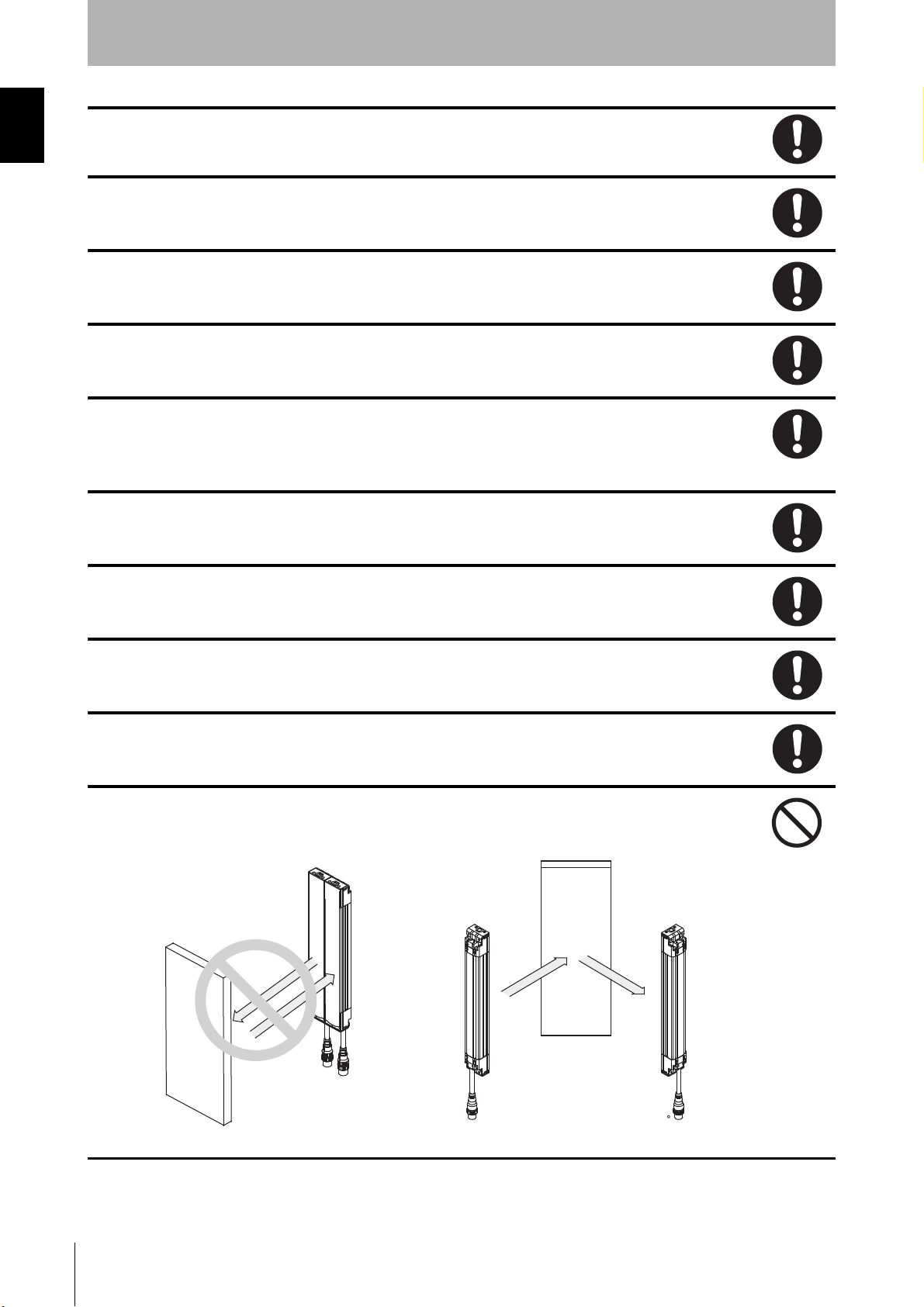
Install the sensor system so that it is not affected by the reflective surface of the F3SJ.
When using more than 1 set of F3SJ, install them so that mutual interference does not occur,
such as by configuring series connections or using physical barriers between adjacent sets.
Make sure that the F3SJ is securely mounted and its cables and connectors are properly
secured.
Make sure that foreign material such as water, oil, or dust does not enter the F3SJ or the
connector while the cap is removed.
Do not use the sensor system with mirrors in a retro-reflective configuration as shown
below.Doing so may hinder detection. It is possible to use mirrors to "bend" the detection zone to
a 90-degree angle.
Reflector
vi
F3SJ-A
User’s Manual
Position with retro-reflection
Reflector
Position with detection zone bent at 90
Page 9
Perform an inspection for all F3SJ as described in "Chapter 6 Checklists". When using series
connections, perform inspections for every connected F3SJ.
For wiring
Connect the load between the output and +24V line (NPN output). Connecting the load between
the output and 0V line will result in a dangerous condition because operation is reversed to "ON
when blocked".
Do not short-circuit the output line to the 0V line. Otherwise, the output is always ON. Also, the
+24V of the power supply must be grounded so that output does not turn ON due to grounding of
the output line.
Configure the system by using the optimal number of safety outputs that satisfy the requirements
of the necessary safety category.
Do not connect each line of F3SJ to a DC power supply of more than 24VDC+20%. Also, do not
connect to an AC power supply. Failure to do so may result in electric shock.
Introduction
For the F3SJ to comply with IEC 61496-1 and UL 508, the DC power supply unit must satisfy all
of the following conditions:
• Must be within the rated power voltage (24V DC
• Must have tolerance against the total rated current of devices if it is connected to multiple
devices
• Must comply with EMC directives (industrial environment)
• Double or reinforced insulation must be applied between the primary and secondary circuits
• Automatic recovery of overcurrent protection characteristics (reversed L sagging)
• Output holding time must be 20ms or longer
• Must satisfy output characteristic requirements for class 2 circuit or limited voltage current
circuit defined by UL508. Refer to p.158 for details.
• Must comply with laws and regulations, regarding EMC and electrical equipment safety, of the
country or region where the F3SJ is used (Ex: In EU, the power supply must comply with the
EMC Directive and the Low Voltage Directive.)
Double or reinforced insulation from hazardous voltage must be applied to all input and output
lines. Failure to do so may result in electric shock.
Extension of the cable must be within a specified length. If it isn't, safety function may not work
properly, resulting in danger.
± 20%)
F3SJ-A
User’s Manual
E
vii
Page 10

Introduction
Other
To use the F3SJ in PSDI mode (Reinitiation of cyclic operation by the protective equipment), you
must configure an appropriate circuit between the F3SJ and the machine. For details about
PSDI, refer to OSHA1910.217, IEC61496-1, and other relevant standards and regulations.
Do not try to disassemble, repair, or modify this product. Doing so may cause the safety functions
to stop working properly.
Do not use the F3SJ in environments where flammable or explosive gases are present. Doing so
may result in explosion.
Perform daily and 6-month inspections for the F3SJ. Otherwise, the system may fail to work
properly, resulting in serious injury.
viii
F3SJ-A
User’s Manual
Page 11

Precautions for Safe Use
Precautions for Safe Use
Make sure to observe the following precautions that are necessary for ensuring safe use of the product.
• Thoroughly read this manual and understand the installation procedures, operation check procedures, and
maintenance procedures before using the product.
• Loads must satisfy both of the following conditions:
-Not short-circuited
-Not used with a current that is higher than the rating
• Do not drop the product.
• Dispose of the product in accordance with the relevant rules and regulations of the country or area where the
product is used.
Precautions for Correct Use
Precautions for Correct Use
Observe the precautions described below to prevent operation failure, malfunctions, or undesirable effects on
product performance.
Installation environment
•Do not install the F3SJ in the following types of environments:
- Areas exposed to intense interference light, such as direct sunlight
- Areas with high humidity where condensation is likely to occur
- Areas where corrosive gases are present
- Areas exposed to vibration or shock levels higher than in the specification provisions
- Areas where the product may come into contact with water
- Areas where the product may get wet with oil that can solve adhesive
•This is a class A product. In residential areas it may cause radio interference, in which case the
Responsible Person may be required to take adequate measures to reduce interference.
•Do not use radio equipment such as cellular phones, walkie-talkies, or transceivers near the F3SJ.
•F3SJ can be used at altitudes up to 2,000 meters.
Introduction
Wiring and installation
•Make sure to perform wiring while the power supply is OFF. Otherwise, the F3SJ may fail to operate
due to the diagnosis function.
•Do not short-circuit output lines to 0V line. Otherwise a fault of F3SJ may occur.
•When extending the communication line with a cable (twisted-pair wire) other than the dedicated
cable (F39-JC/F39-JD), use a cable with the same or superior specifications.Connect the
shield to the 0V line.
Cable specification (extension cable) p.15
•When replacing the cable connectors with other types of connectors, use connectors that provide a
protection grade of IP54 or higher.
•Properly perform the wiring after confirming the signal names of all the terminals.
•Do not operate the control system until 2 seconds or more (2.2 seconds or more in case of series
connection) after turning ON the power of the F3SJ.
•Be sure to route the F3SJ cable separate from high-potential power lines or through an exclusive
conduit.
•When using a commercially available switching regulator power supply, make sure to ground the FG
terminal (frame ground terminal).
F3SJ-A
User’s Manual
E
ix
Page 12

Introduction
•Install the emitter and receiver so that their vertical direction should match.
•If the protective height is 600 mm or more, use intermediate mounting brackets of specified quantities
and locations according to the dimensions.
If the brackets described above are not used, ratings and performance cannot be not met.
Cleaning
Do not use thinner, benzene, or acetone for cleaning, because they affect the product's resin parts and
paint on the case.
Object detection
The F3SJ cannot detect transparent and/or translucent objects.
F3SJ-A
x
User’s Manual
Page 13
Checking the Contents
Introduction
Before use, confirm that the items below were shipped with the product.
If you find that an item is missing, please contact your local branch office or distributor.
Product Quantity
F3SJ-AN main unit Emitter x 1, Receiver x 1
Top/bottom mounting brackets 4 sets
Checking the Contents
Intermediate mounting brackets Intermediate brackets are included when the protective height of the F3SJ is
600mm or longer. The number of brackets included depends on the total length of
the F3SJ. (4 sets maximum for each emitter/receiver)
Error mode label 1 (includes Japanese and English)
Instruction sheet 1 pair of Japanese and English
User's manual (CD-ROM) 1 (for F3SJ-AP (Japanese/English), for F3SJ-AN
(Japanese/English), Adobe Reader)
F3SJ-A
User’s Manual
E
xi
Page 14

Introduction
How to Read This Manual (Explanation of Symbols)
How to Read This Manual (Explanation of Symbols)
Indicates the description of an essential point regarding a function, such as an important point
regarding operation or advice on how to use it.
Indicates the page number for related content.
Indicates a reference for when there is trouble, or an explanation of difficult words.
xii
F3SJ-A
User’s Manual
Page 15

Contents
Introduction
Legislation and Standards i
Terms and Conditions Agreement ii
Precautions on Safety iv
Precautions for Safe Use ix
Precautions for Correct Use ix
Checking the Contents xi
How to Read This Manual (Explanation of Symbols) xii
Chapter1 Overview and Specifications 1
Basic Configuration and Names 2
Application Examples 5
Detect the Approach to a Hazardous Zone 5
Using Multiple Sets in Combination 6
For a System in which a Workpiece Crosses Detection Zone (Muting Function) 6
For a System that Has a Machine Within a Detection Zone 7
To Notify a Person of Proximity to a Detection Zone (Warning Zone Function) 8
Features 9
Contents
Protective Height Available in Incremental Sizes 9
Easy-to-Read Light Level and Error Mode Display 9
Providing Tools for Setting 9
Additional Safety Functions 9
Enhanced Mutual Interference Prevention 9
Muting/Override Function are Provided 10
Indicator Display Patterns 11
Internal Indicator for Basic System 11
Internal Indicator for Muting System 12
Display Patterns of the Incident Light Level Indicator 13
Ratings 14
Ratings/Specifications 14
Model Name List/Response Times 17
Power Cable Length 22
Compatibility with former version 23
Chapter2 System Configuration and Functions 25
How to Select a System 26
Selection Flow Chart 26
Combination of Functions 26
Basic System 27
Wiring Diagrams 27
F3SJ-A
User’s Manual
E
xiii
Page 16

Introduction
Interlock Function 29
External Test Function 31
Contents
Self-Test Function 31
Auxiliary Output (Non-Safety Output) 32
Resetting Lockout 33
External Device Monitoring Function 34
Muting System 35
Upgrading F3SJ for Muting System 36
Standard Muting Mode 38
Wiring Diagrams 40
Installation Standard for Muting Sensors 42
Installation Example 1 of Standard Muting Mode (using 2 muting sensors) 42
Installation Example 2 of Standard Muting Mode (using 4 muting sensors) 46
Override Function 52
External Test Function 54
Self-Test Function 54
Auxiliary Output (Non-Safety Output) 55
Resetting Lockout 55
External Device Monitoring Function (EDM) 55
Chapter3 What can be done by the setting tool 57
Using the Setting Tool 58
F3SJ Version 58
List of Functions that Can Be Changed by the Setting Tool 59
Preparation 61
Setting Console 61
PC Tool for F3SJ 61
F3SJ Status When Setting Tool Is Connected 63
Maintenance Status 63
Internal Indicators During Maintenance Status 63
Internal Indicator While Writing/Monitoring with the Setting Tool 64
Protection of Setting by Password 65
Access Qualification 65
Password Change 65
If You Forget the Password: 65
Setting Adjusted to Application 66
Fixed Blanking Function 66
xiv
F3SJ-A
User’s Manual
Floating Blanking Function 70
Warning Zone Function 77
Muting Function 80
Override Function 91
Page 17

Setting Zone Adjacent Conditions 91
Indicator/Input & Output Setting 94
Introduction
Auxiliary Output (Non-Safety Output) 94
Designated Beam Output Function 96
External Indicator Output (Non-Safety Output) 98
Interlock Function 99
External Device Monitoring Function 101
Operating Range Change 102
Operating Range Change Function 102
Operation Monitoring 103
Incident Light Level Display 103
Disturbance Light Level Display 103
Status Information Display 104
Maintenance Information 105
Error History 105
Power-on Time 105
Load Switching Frequency 107
Setting Recovery 108
Setting Recovery Function 108
Contents
Other 109
Safety Distance Calculation Function 109
Connection Cable Length Calculation Function 109
Rated Response Time Check 109
Chapter4 Wiring/Installation 111
Installation Conditions 112
Detection Zone and Approach 112
Safety Distance 113
Distance from Reflective Surfaces 116
Mutual Interference Prevention 117
Series Connection 120
Connection Procedure 122
Attaching External Indicators 124
Connection Procedure 124
Output Operation 125
Setting Change by the Setting Tool 125
Dimensions 126
When Using Standard Mounting Brackets 126
When Using Optional Mounting Brackets 129
F39-A01Po-PAC External Indicator Set 146
When Using Spatter Protection Covers 146
F3SJ-A
User’s Manual
E
xv
Page 18

Introduction
Setting Tool 147
Mounting a Protect Bar 148
Contents
Mounting an Environment-Resistant Case 150
Mounting 152
Top/Bottom Mounting Brackets 152
Intermediate Mounting Brackets 152
Mounting Procedure 153
Adjustment Procedure 156
Wiring 157
Wiring Precautions 157
Power Supply Unit 158
Wiring Procedure 159
Chapter5 Input/Output Circuit and Applications 165
Input/Output Circuit 166
Wiring Examples 167
Using only F3SJ 167
Connecting 2 Muting Sensors 168
Connecting 4 Muting Sensors 169
Connecting to a G9SA-301-P 170
Using a reduced wiring connector 171
Chapter6 Checklists 173
Pre-Operation Checklists 174
Checklists 174
Maintenance Checklists 177
Checklists 177
Chapter7 Appendix 179
Troubleshooting 180
Lockout State 180
Problem under other state than lockout 187
Accessories (Sold Separately) 189
Glossary 196
Related Standards 200
xvi
F3SJ-A
User’s Manual
International Standards 200
European Standards 200
U.S. Federal Regurations 200
U.S. Standards 200
Canadian Standards 201
Page 19

Revision History 202
Introduction
Contents
F3SJ-A
User’s Manual
E
xvii
Page 20

Introduction
Contents
xviii
F3SJ-A
User’s Manual
Page 21

Chapter1 Overview and Specifications
Basic Configuration and Names 2
Application Examples 5
Features 9
Indicator Display Patterns 11
Ratings 14
Ratings/Specifications 14
Model Name List/Response Times 17
Power Cable Length 22
Compatibility with former version 23
Chapter1 Overview and Specifications
F3SJ-A
User’s Manual
E
1
Page 22

Overview and Specifications
Emitter
Receiver
Cap
Indicator
Beam
Extension cable
Beam center-line mark
Connection cable (Grey)
Connection cable (Black)
To attach or detach the cap
and power cable,
remove 4 screws shown above.
F3SJ-AN-
Basic Configuration and Names
Chapter1 Basic Configuration and Names
This section describes the system configuration and part names of the F3SJ.
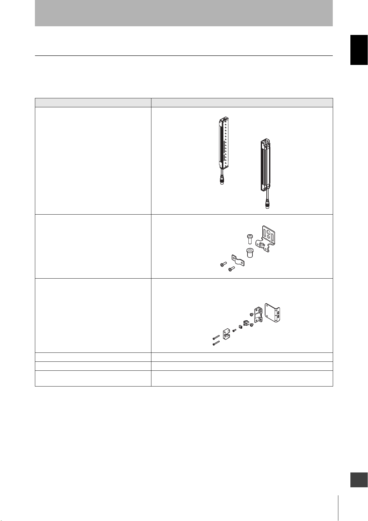
Component Model name Description
Emitter, receiver F3SJ-AN Select a model name based on the required protective
height and detection capability. (Cap and connection cable
are included.)
The model name can be understood as follows:
1: Protective height (mm)
2: Output type (N=NPN output type)
3: Detection capability (mm)
To distinguish between the emitter and receiver, find the labels attached to the front of the F3SJ. The label on the emitter reads
"EMITTER" and the label on the receiver reads "RECEIVER".
These words are printed on the side where the power supply connector is located.
4: L is emitter, D is receiver, blank is a set of an emitter and
a receiver
2
F3SJ-A
User’s Manual
Page 23
Extension
cable
Overview and Specifications
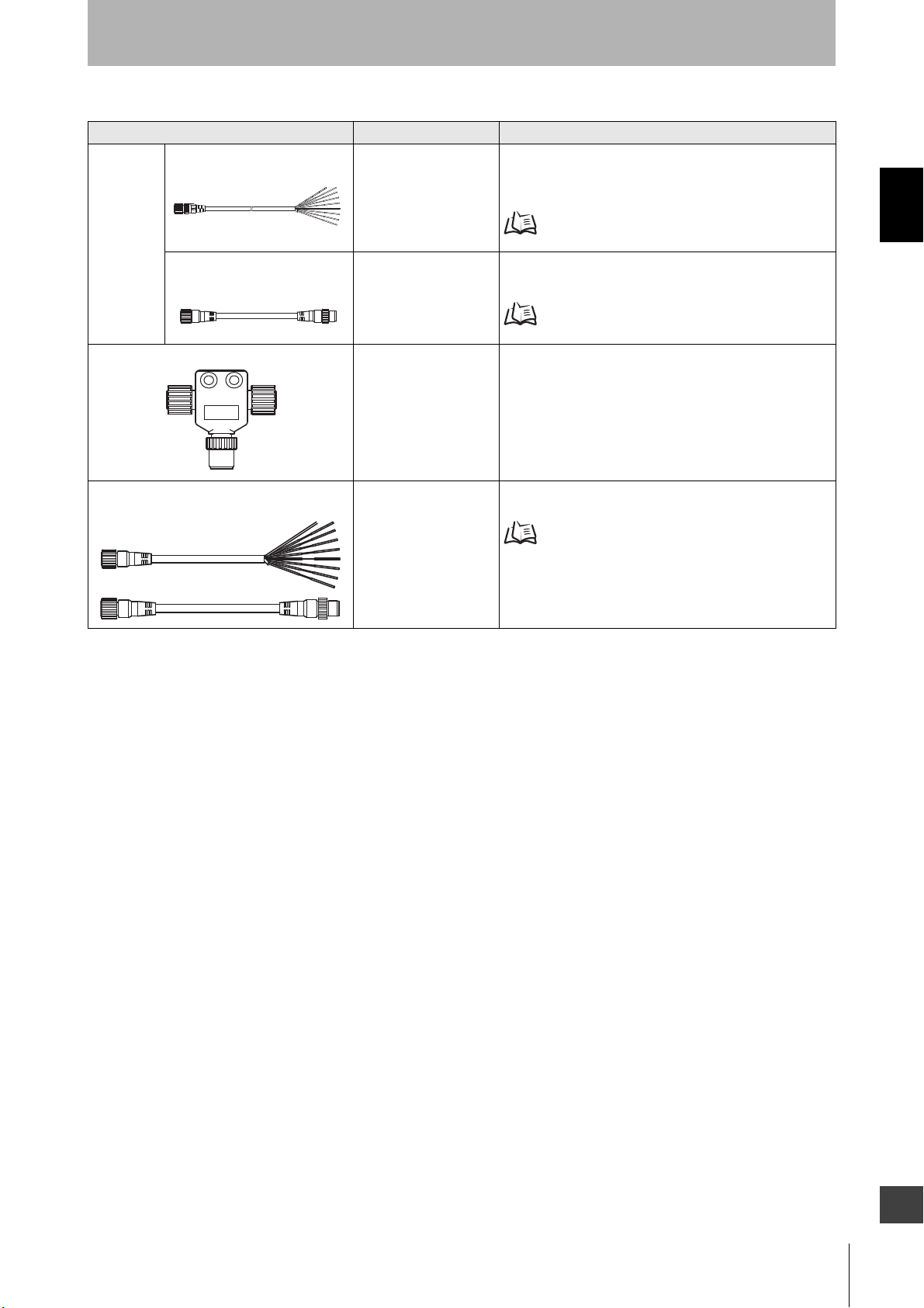
Component Model name Description
Cable with connector on one
end
F39-JCA
(to be discontinued)
F39-JDA
This extension cable is used to connect the F3SJ to a
controller with discrete terminals(G9SA-301-P)or to a safety
processing system (e.g. DeviceNet safety).
p.189
Chapter1 Basic Configuration and Names
Cable with connectors on both
ends
F39-JCB
(to be discontinued)
F39-JDB
This extension cable is used when the length of the
connection cable is insufficient. The length can be selected.
p.189
Reduced Wiring Connector F39-CN5 This connector is used for a reduced wiring system, in
combination with the following cables for reduced wiring
system.
Cable for reduced wiring
(2 cables per set, for emitter and receiver)
F39-JDBA These cables are used for a reduced wiring system, a set of
connector cables for emitter's ends and receiver's ends.
p.190
F3SJ-A
User’s Manual
E
3
Page 24
Overview and Specifications
Components to be selected if necessary
Chapter1 Basic Configuration and Names
Optional bracket - Use this bracket (sold separately) for dedicated applications.
Component Model name Description
p.129
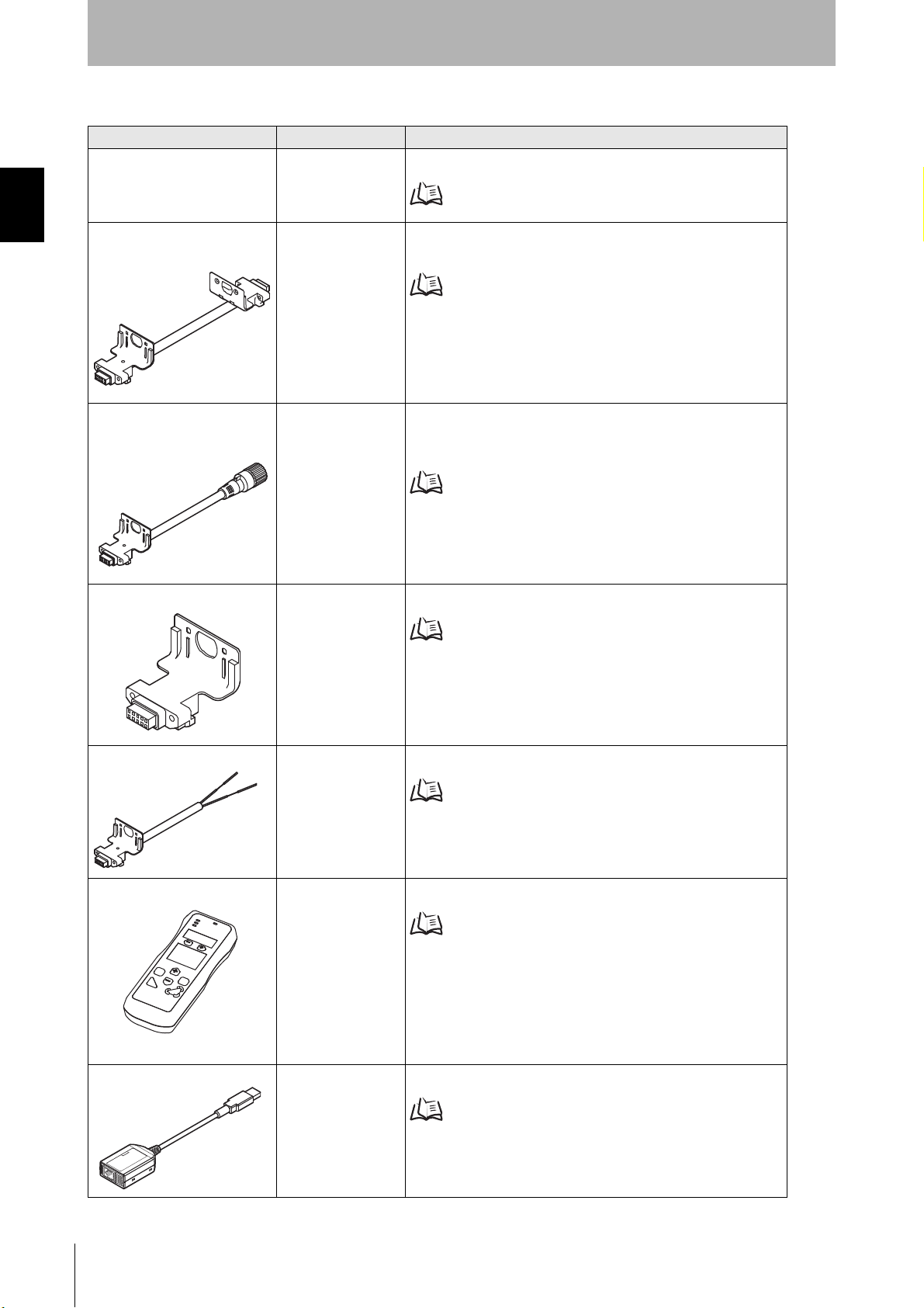
Series connection cable for
close contact
Series connection cable for
extension
Key cap for muting F39-CN6 Required when using muting function. (Case color : Orange)
F39-JJR06L
F39-JJR15L
F39-JJR3W Required for connecting multiple sets of F3SJ in a series. The F39-
Required for connecting multiple sets of F3SJ in a series. It is used
when you wish to perform series connection with minimum length.
Connection Procedure p.122
JJR3W can be used for extension with cable with connectors on
both ends(F39-JCB/F39-JDB).
Connection Procedure p.123
Muting System p.35
Indicator cable F39-JJ3N
F39-A01P-PAC
Setting console F39-MC21 Required to change functional setting or investigate status of F3SJ.
PC tool for F3SJ F39-GWUM Required to change functional setting or investigate status of F3SJ.
Required when attaching external indicator(s) to the F3SJ.
Attaching External Indicators p.124
Using the Setting Tool p.58
Using the Setting Tool p.58
F3SJ-A
4
User’s Manual
Page 25
Application Examples
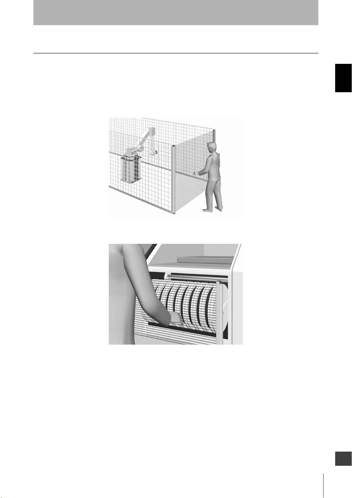
Detect the Approach to a Hazardous Zone
The F3SJ should be installed where workers require frequent access in order to perform tasks such as
maintenance, and where physical barriers are difficult to install.
Detect the Approach of a Person
Overview and Specifications
Chapter1 Application Examples
Detect a Person's Limbs
F3SJ-A
User’s Manual
E
5
Page 26
Chapter1 Application Examples
Overview and Specifications
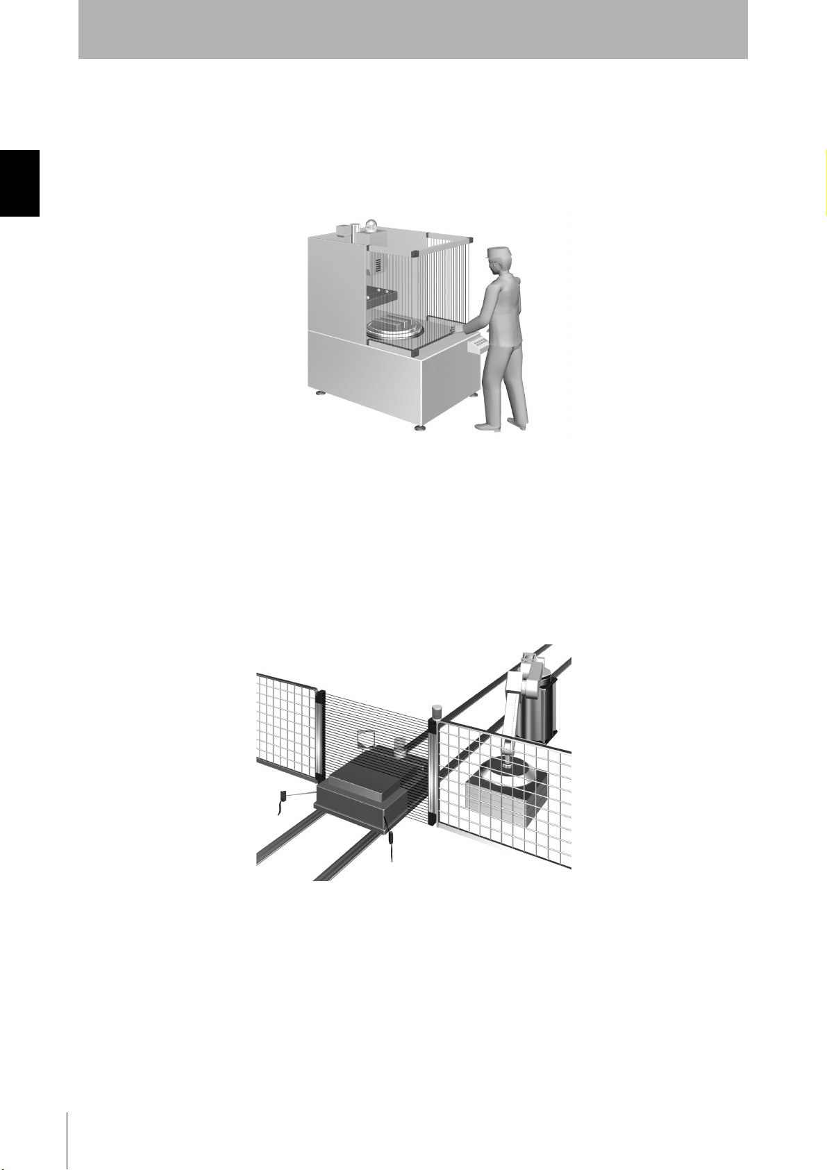
Using Multiple Sets in Combination
By installing sensors on both sides of a machine as well as in front, you can move workpieces in and
out more efficiently than when a physical barrier is installed. If the sensors are aligned in a U-shape,
series-connection cables can be used between sets (up to 4 sets), so that only one control device is
used, drastically reducing the amount of wiring in the panel.
For a System in which a Workpiece Crosses Detection Zone
(Muting Function)
Enter of a workpiece can be detected by a sensor and the detection zone can be temporarily disabled
only while the workpiece is crossing the whole or specified zone. This function is called muting.
Muting is when a work piece is allowed to enter into a dangerous zone without tripping the F3SJ and
stopping the process. Muting sensors are installed and arranged as to detect the work piece and not a
human entering the zone.
F3SJ-A
6
User’s Manual
Page 27
Overview and Specifications
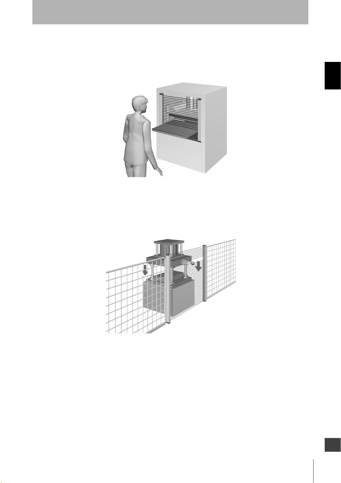
For a System that Has a Machine Within a Detection Zone
When the Zone Is Fixed (Fixed Blanking Function):
For a system in which a fixed facility such as a worktable or a conveyor interrupts specific beams, the
fixed blanking function can be used to disable the specific beams.
When the Zone Is Movable (Floating Blanking Function):
If a part of the machine can move within the detection zone, the floating blanking function can be used
to disable a part of the detection zone.
You can configure a number of beams to be interrupted by an object so that the safety function works
only if more beams than the number are interrupted.
Chapter1 Application Examples
F3SJ-A
User’s Manual
E
7
Page 28
Overview and Specifications
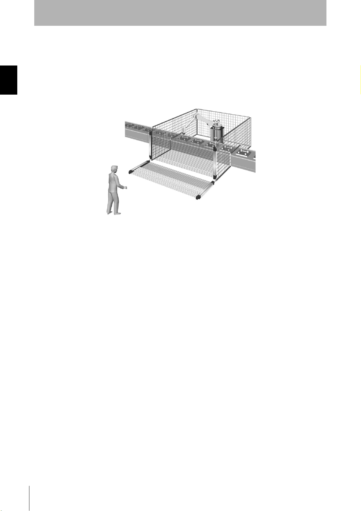
To Notify a Person of Proximity to a Detection Zone
Chapter1 Application Examples
(Warning Zone Function)
This function notifies a person that he/she is getting close to a detection zone before activating the
safety functions. It can be used to prevent the unintended stopping of a machine due to the approach
of a person.
Part of a detection zone is configured as a warning zone.
Detection Zone
Detection Zone
Warning Zone
F3SJ-A
8
User’s Manual
Page 29
Features
r
Protective Height Available in Incremental
Overview and Specifications
Chapter1 Features
Sizes
Series Protective height Detection capability
F3SJ-AN14 245mm to 2117mm (in 9mm increments) Dia. 14mm
F3SJ-AN20 245mm to 2,495mm (in 15mm increments) Dia. 20mm
F3SJ-AN25 260mm to 2,500mm (in 20mm increments) Dia. 25mm
F3SJ-AN30 245mm to 2,495mm (in 25mm increments) Dia. 30mm
F3SJ-AN55 270mm to 2,470mm (in 50mm increments) Dia. 55mm
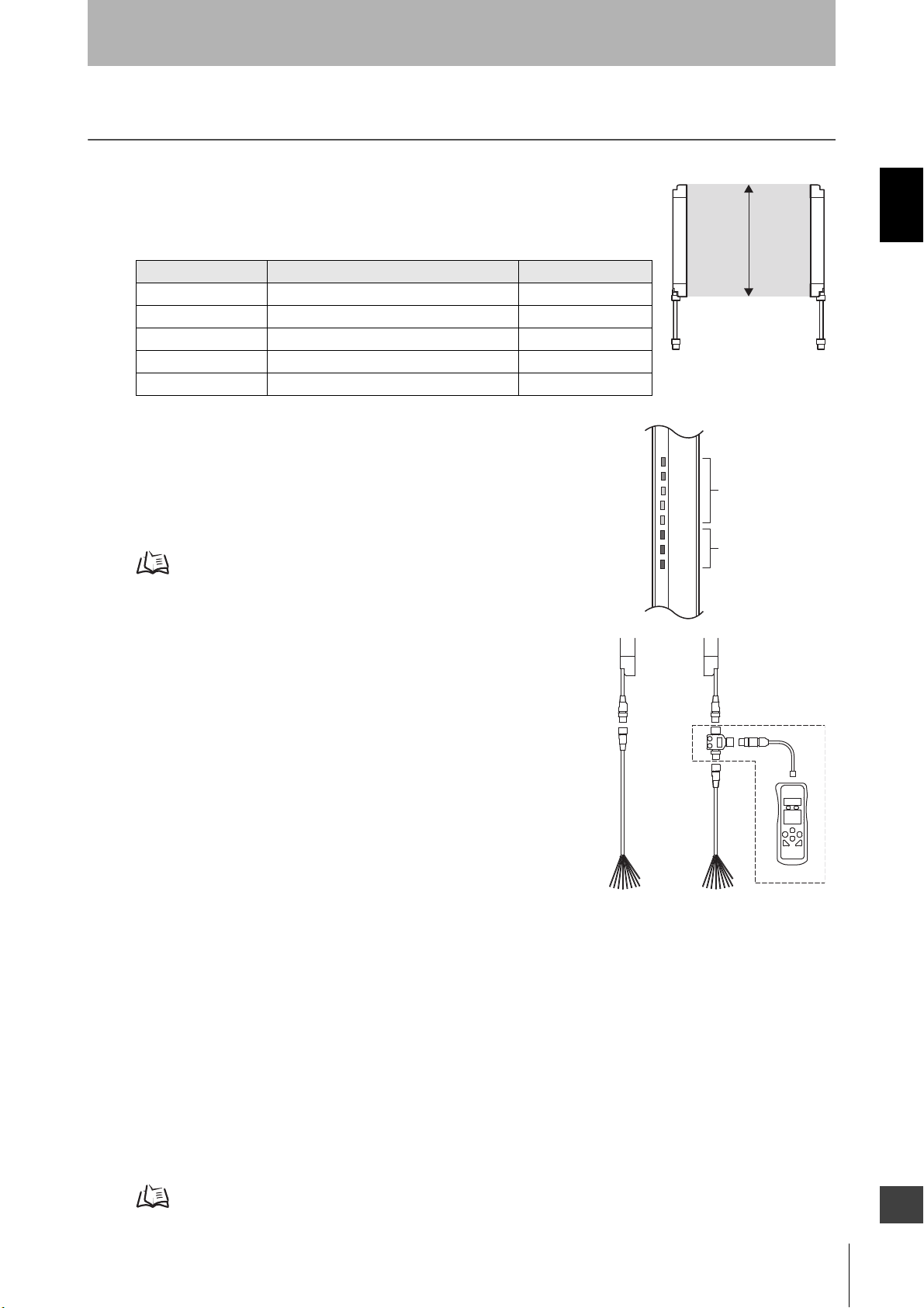
Easy-to-Read Light Level and Error Mode
Display
Beam alignment is simplified using 5 LEDs that display the incident light
level.
Error status is indicated on 3 additional LEDs when an error occurs.
Indicator Display Patterns p.11
Providing Tools for Setting
Two types of tools are provided to change functional setting of
F3SJ. (Accessories sold separately)
These tools allow you to change functions or check status of F3SJ,
taking more advantage of F3SJ.
•Setting Console F39-MC21
•PC Tool For F3SJ F39-GWUM
LEVEL
5
4
3
2
1
C
B
A
Protective
height
Incident light
level indicato
Error mode
indicator
Additional Safety Functions
•External test (light emission stop)
•External device monitoring function
•Interlock function
•Fixed/Floating Blanking Function
(Configuration by the setting tool is required)
Enhanced Mutual Interference Prevention
When the series connection function is used, mutual interference is prevented in up to 400 beams in 4
sets.
When F3SJ are used individually, the newly designed interference light detection and cycle shift
algorithm prevents mutual interference in up to 3 sets.
The effect of interference between the F3SJ and other photoelectric sensors can be reduced by using
the setting tool to shorten the operating range.
p.117
F3SJ-A
User’s Manual
E
9
Page 30

Chapter1 Features
Overview and Specifications
Muting/Override Function are Provided
An F3SJ by itself can operate with muting or override function without using a controller.
Definition of muting function and override function p.196
10
F3SJ-A
User’s Manual
Page 31

Indicator Display Patterns
4. Interlock indicator (Yellow)
3. Power indicator (Green)
2. Error mode
indicator
1. Incident light level
indicator
EMITTER
LEVEL
POWER
ERROR ERROR
INTLK
EDM
Blanking
(TEST)
5
4
3
2
1
C
B
A
5
4
3
2
1
C
B
A
RECEIVER
LEVEL
OFF
ON
*1
LEVEL-5 (Green)
LEVEL-1 (Orange)
LEVEL-2 (Orange)
LEVEL-3 (Orange)
LEVEL-4 (Green)
ERROR-C (Red)
ERROR-B (Red)
ERROR-A (Red)
LEVEL-1 (Orange)
LEVEL-2 (Orange)
LEVEL-3 (Orange)
LEVEL-4 (Green)
LEVEL-5 (Green)
ERROR-B (Red)
ERROR-
A
(Red)
ERROR-C (Red)
1. Incident light
level indicator
2. Error mode
indicator
8. ON-state indicator (Green)
7. OFF-state indicator (Red)
Emitter Receiver
5. External device monitoring indicator (Green)
[Muting input 1 indicator]
6. Blanking/Test indicator(Green)
[Muting input 2 indicator]
9. Not used (Green)
[Muting error indicator]
10. Not used (Green)
[Blanking/Test indicator]
A set of square brackets, [ ], indicates
name of an indicator under muting system.
*1 This label comes with the F39-CN6 key
cap for muting. Affix this label when a
keycap is used.
Ǟ30
Ǟ30
Overview and Specifications
Chapter1 Indicator Display Patterns
Internal Indicator for Basic System
Shown below are indication statuses of F3SJ's internal indicator when you purchased.
No. Indicators
1 Incident light level
indicator
2 Error mode indicator ERROR-A to C ON/
3 Power indicator POWER ON Turns ON while the power is ON.
4 Interlock indicator INTLK ON Turns ON when F3SJ is in interlock state.
5 External device
monitoring indicator
6 Blanking/Test indicator BLANKING/
LEVEL-1 to 5 ON Indication status of LEVEL-1 to 5 shows the incident light level
EDM ON Turns ON when an input is given to external device monitoring
TEST
ON/
Blinking
status of the F3SJ.
Blinking
Blinking Blinks during maintenance status.
Blinking Blinks when in lockout.
ON Turns ON when the blanking function and warning zone function
Turns ON or blinks only when the F3SJ enters lockout, and the
cause of the error is indicated by the status of ERROR-A to C
indicators.When F3SJ are series-connected, the error mode
indicator lamps turn ON or blink according to the details of each
error. Affix the error mode label (included) near the F3SJ to
allow for quick troubleshooting when errors occur. For details of
the error mode, see "Chapter 7 Troubleshooting".
input.
Description
are enabled.
Blinking Blinks when external test is being performed.
E
F3SJ-A
User’s Manual
11
Page 32

Overview and Specifications
No. Indicators
7 OFF-state indicator OFF ON Turns ON when safety outputs are OFF.
Chapter1 Indicator Display Patterns
8 ON-state indicator ON ON Turns ON when safety outputs are ON.
9– – – –
10 – – – –
ON/
Blinking
Blinking Blinks at following states:
- Lockout state
- One or more beams are blocked during the maintenance status
Blinking Blinks when no beams are blocked during the maintenance
status
Description
Internal Indicator for Muting System
Shown below are internal indicator statuses while the keycap for muting is being attached.
No. Indicators
1 Incident light level
indicator
2 Error mode indicator ERROR-A to C ON/
3 Power indicator POWER ON Turns ON while the power is ON.
4 Interlock indicator INTLK ON Turns ON when F3SJ is in interlock state.
5 Muting input 1 indicator MUTE1 ON Turns ON when an input is given to muting input 1.
6 Muting input 2 indicator MUTE2 ON Turns ON when an input is given to muting input 2.
7 OFF-state indicator OFF ON Turns ON when safety outputs are OFF.
8 ON-state indicator ON ON Turns ON when safety outputs are ON.
9 Muting error indicator MUTING
10 Blanking/Test indicator BLANKING/
LEVEL-1 to 5 ON Indication status of LEVEL-1 to 5 shows the incident light level
ERROR
TEST
ON/
Blinking
status of the F3SJ.
Turns ON or blinks only when the F3SJ enters lockout, and the
Blinking
Blinking Blinks during maintenance status.
Blinking Blinks when in lockout.
Blinking Blinks during muting/override.
Blinking Blinks during muting/override.
Blinking Blinks at following states:
Blinking Blinks when no beams are blocked during the maintenance
ON Turns ON when a muting error occurs.
ON Turns ON when the blanking function is enabled.
Blinking Blinks when external test is being performed.
cause of the error is indicated by the status of ERROR-A to C
indicators.When F3SJ are series-connected, the error mode
indicator lamps turn ON or blink according to the details of each
error. Affix the error mode label (included) near the F3SJ to
allow for quick troubleshooting when errors occur. For details of
the error mode, see "Chapter 7 Troubleshooting".
- Lockout state
- One or more beams are blocked during the maintenance status
status
Description
12
For an explanation of terminology such as function names, refer to the glossary.
F3SJ-A
User’s Manual
Glossary p.196
Page 33

Overview and Specifications
ON OFF
5
3
5
4
3
2
1
Display Patterns of the Incident Light Level Indicator
Chapter1 Indicator Display Patterns
incident light level indicator
5
4
2
1
4
3
2
1
5
4
3
2
1
5
4
3
2
1
Safety Output ON ON ON OFF OFF OFF
Incident light level
170% or
higher
Less than
170%
~
130%
Less than
130%
~
100%
Less than
100%
~
75%
Less than
75%
~
50%
Less than
Operation is possible with incident light level of 100% or more, but to ensure stability, operate when all incident light
level indicators
5
4
3
2
1
50%
F3SJ-A
User’s Manual
E
13
Page 34

Chapter1 Ratings
Overview and Specifications
Ratings
Ratings/Specifications
In the model names in this table, the contain the 4-digit number indicating the protective height
(mm).
F3SJ-A
N14
Detection capability Opaque objects Opaque objects Opaque objects Opaque objects Opaque objects
Diameter 14mm Diameter 20mm Diameter 25mm Diameter 30mm Diameter 55mm
Beam gap 9mm 15mm 20mm 25mm 50mm
Number of beams 26 to 234 16 to 166 13 to 125 10 to 100 6 to 50
Protective height 245 to 2,117mm 245 to 2,495mm 260 to 2,500mm 245 to 2,495mm 270 to 2,470mm
Lens diameter Diameter 5mm
Operating range 0.2 to 9m (for protective height up to 1649 mm)
0.2 to 7m (for protective height 1655 mm or greater)
(Operating range can be reduced to 0.5m through the setting tool)
Response time ON to OFF: 10ms to 27.5ms max., OFF to ON: 40ms to 110ms max. (when incidence is
stable).
Refer to p.17 for details.
Startup waiting time 2s max. (2.2s max in case of series connection)
Power supply voltage(Vs) 24VDC ± 20% (ripple p-p10% max.)
Current consumption
(no load)
Light source Infrared LED (870nm wavelength)
Effective aperture angle (EAA) Within ±2.5 ° for the emitter and receiver at a detection distance of at least 3 m according to
Safety outputs(OSSD) NPN transistor outputs x 2, Load current 300mA max, Residual voltage 2V max. (except for
Emitter
Receiver Up to 50 beams: 68 mA max., 51 to 100 beams: 90 mA max., 101 to 150 beams: 111 mA max.,
Up to 50 beams: 76 mA max., 51 to 100 beams: 106 mA max., 101 to 150 beams: 130 mA max.,
151 to 200 beams: 153 mA max., 201 to 234 beams: 165 mA max.
151 to 200 beams: 128 mA max., 201 to 234 beams: 142 mA max.
IEC61496-2
voltage drop due to cable extension)(including inductance load), Maximum capacity load 2.2
F3SJ-A
N20
F3SJ-A
N25
F3SJ-A
N30
F3SJ-A
N55
μF, leakage current 2mA max. (This may be different from previously used logic (ON/OFF)
because safety circuit is used.)
Auxiliary output 1 (Non-safety output) NPN transistor output x 1, Load current 300mA max., Residual voltage 2V max. (except for
voltage drop due to cable extension), leakage current 1mA max.
Auxiliary output 2 (non-safety output, a
function for a basic system)
External indicator output (Non-safety
output)
Output operation mode Safety outputs : ON when receiving light
NPN transistor output x 1, load current 50mA or less, residual voltage 2V or less (excluding
influence by cable extension), leakage current 1mA or less
Connectable external indicator
- Incandescent lamp : 24VDC, 3 to 7W
- LED lamp : Load current 10 to 300mA max.
Leakage current 1mA max.
(An indicator cable F39-JJ3N or F39-A01P-PAC is required when using an external
indicator.)
Auxiliary output 1 : Reverse output of safety output (operation mode can be changed by the
setting tool)
Auxiliary output 2: Turns ON when 30,000 hours of power-on time passes (operation mode can
be changed by the setting tool)
External indicator output 1: Reverse output of safety output (for basic system), ON during
muting/override (for muting system)
(Operation mode can be changed by the setting tool)
External indicator output 2: ON in lockout (for basic system), ON during muting/override (for
muting system) (operation mode can be changed by the setting tool)
14
F3SJ-A
User’s Manual
Page 35

Overview and Specifications
F3SJ-A
N14
Input voltage Test input, interlock selection input, reset input, and muting input are all:
ON voltage: 0 to 1.5V (short-circuit current 3mA max.)
OFF voltage: 9 to 24Vs, or open
External device monitoring input is:
ON voltage: 0 to 1.5V (short-circuit current 5mA max.)
OFF voltage: 9 to 24Vs, or open
Indicators Emitter Incident light level indicators (green LED x 2, orange LED x 3): ON based on the amount of
incident light
Error mode indicators (red LED x 3): Blink to indicate error details
Power indicator (green LED x 1): ON while power is ON
Interlock indicator (yellow LED x 1): ON when in interlock/Blinks when in lockout
External device monitoring indicator (muting input 1 indicator), Blanking/ Test indicator (muting
input 2 indicator) (green LED x2): ON/Blink according to function
Receiver Incident light level indicators (green LED x 2, orange LED x 3): ON based on the amount of
incident light
Error mode indicators (red LED x 3): Blink to indicate error details
OFF-statet indicator (red LED x 1): ON when safety outputs are OFF/ Blinks when in lockout
ON-state indicator (green LED x 1): ON when safety outputs are ON
Muting error indicator, Blanking/Test indicator (green LED x 2): ON/Blink according to function
Mutual interference prevention
function
Series connection Time division emission by series connection
Test function - Self-test (After power ON, and during operation)
Safety-related functions - Start interlock, restart interlock (The setting tool is required when muting function is used)
Connection method Connector method (M12, 8-pin)
Protection circuit Output short-circuit protection, and power supply reverse polarity protection
Ambient temperature During operation: -10 to 55°C (without freezing), During storage: -30 to 70°C
Ambient humidity During operation: 35 to 85%RH (no condensation), During storage: 35 to 95%RH
Ambient light intensity Incandescent lamp: receiving-surface light intensity of 3,000 Ix max., Sunlight: receiving-
Insulation resistance 20MΩ or higher (500VDC)
Dielectric strength voltage 1, 000VAC, 50/60Hz, 1min
Degree of protection IP65 (IEC60529)
Vibration resistance Malfunction: 10 to 55Hz, Multiple amplitude of 0.7mm, 20 sweeps each in X, Y, and Z directions
Shock resistance Malfunction: 100m/s
Connection cable, Series connection
cable (F39-JJRL, JJR3W)
Extension cable (F39-JCA, JCB,
JDA, JDB)
Interference light avoidance algorithm, operating range change function
- Number of connections: Up to 4 sets
- Total number of beams: Up to 400
- Maximum cable length between 2 sets of sensors: 15m
- External test (light emission stop function by test input)
- External device monitoring
- Muting (Includes lamp breakage detection and override functions. F39-CN6 key cap for
muting is required)
- Fixed blanking (configuration by the setting tool is required)
- Floating blanking (configuration by the setting tool is required)
surface light intensity of 10,000 Ix max.
Dia. 6 mm, 8-wire (0.15mm
Dia. 6.6 mm, 8-wire (0.3mm
Allowable bending radius of R36mm.
(To extend a cable, use an equivalent or higher-performance cable (twisted-pair wire) , and do
not use the cable in the same duct as that for high-voltage cables or power cables)
F3SJ-A
N20
2
, 1,000 times each in X, Y, and Z directions
2
x 8) with braided shield, Allowable bending radius R5mm
2
x 4P, conductor resistance 0.058 ohm/m), with braided shield,
F3SJ-A
N25
F3SJ-A
N30
F3SJ-A
N55
For details about extension lengths (power cable length) p.22
Chapter1 Ratings
For details about twisted pair wire (single connector cable)
p.159
F3SJ-A
User’s Manual
E
15
Page 36

Overview and Specifications
Chapter1 Ratings
F3SJ-A
N14
Material Casing (including metal parts on both ends): Aluminum, zinc die-cast
Cap: ABS resin
Optical cover: PMMA resin (acrylic)
Cable: Oil resistant PVC
Weight (packaged) - F3SJ-AN14
Weight (g)=(protective height) x 1.7+ α
- F3SJ-AN20/F3SJ-AN25/F3SJ-AN30
Weight (g)=(protective height) x 1.5+ α
- F3SJ-AN55
Weight (g)=(protective height) x 1.4+ α
The values for α are as follows:
When protective height is between 245 and 596mm, α=1100
When protective height is between 600 and 1130mm, α=1500
When protective height is between 1136 and 1658mm, α=2000
When protective height is between 1660 and 2180mm, α=2400
When protective height is between 2195 and 2500mm, α=2600
Accessories Instruction sheet, top and bottom mounting brackets, intermediate mounting brackets *, error
mode label, user’s manual (CD-ROM)
* The number of intermediate mounting brackets depends on the total length of the F3SJ.
- F3SJ total length is from 600 to 1,130mm: 1 set for each the emitter and receiver is included
- F3SJ total length is from 1136 to 1,658mm: 2 sets for each the emitter and receiver are
included
- F3SJ total length is from 1660 to 2,180mm: 3 sets for each the emitter and receiver are
included
- F3SJ total length is from 2195 to 2500mm: 4 sets for each the emitter and receiver are
included
Applicable standards IEC61496-1, EN61496-1, UL61496-1 Type 4ESPE (Electro-Sensitive Protective Equipment)
IEC61496-2, CLC/TS 61496-2, UL61496-2 Type 4AOPD (Active Opto-electronic Protective
Devices)
IEC61508, EN61508 SIL3, EN ISO 13849-1:2008 (Category 4, PL e), ISO 13849-1:2006
(Category 4, PL e)
Safety-related characteristic data
(EN 61508:2010)
See http://www.fa.omron.co.jp/safety_6en/
F3SJ-A
N20
F3SJ-A
N25
F3SJ-A
N30
F3SJ-A
N55
16
F3SJ-A
User’s Manual
Page 37

Overview and Specifications
Model Name List/Response Times
F3SJ-A
N14
- - - - F3SJ-A0270N55 6 beams 10ms 40ms
- - - - F3SJ-A0320N55 7 beams 10ms 40ms
- - - - F3SJ-A0370N55 8 beams 10ms 40ms
- - - - F3SJ-A0420N55 9 beams 10ms 40ms
- - - F3SJ-A0245N30 F3SJ-A0470N55 10 beams 10ms 40ms
- - - F3SJ-A0270N30 F3SJ-A0520N55 11 beams 10ms 40ms
- - - F3SJ-A0295N30 F3SJ-A0570N55 12 beams 10ms 40ms
- - F3SJ-A0260N25 F3SJ-A0320N30 F3SJ-A0620N55 13 beams 10ms 40ms
- - F3SJ-A0280N25 F3SJ-A0345N30 F3SJ-A0670N55 14 beams 10ms 40ms
- - F3SJ-A0300N25 F3SJ-A0370N30 F3SJ-A0720N55 15 beams 10ms 40ms
- F3SJ-A0245N20 F3SJ-A0320N25 F3SJ-A0395N30 F3SJ-A0770N55 16 beams 10ms 40ms
- F3SJ-A0260N20 F3SJ-A0340N25 F3SJ-A0420N30 F3SJ-A0820N55 17 beams 11ms 44ms
- F3SJ-A0275N20 F3SJ-A0360N25 F3SJ-A0445N30 F3SJ-A0870N55 18 beams 11ms 44ms
- F3SJ-A0290N20 F3SJ-A0380N25 F3SJ-A0470N30 F3SJ-A0920N55 19 beams 11ms 44ms
- F3SJ-A0305N20 F3SJ-A0400N25 F3SJ-A0495N30 F3SJ-A0970N55 20 beams 11ms 44ms
- F3SJ-A0320N20 F3SJ-A0420N25 F3SJ-A0520N30 F3SJ-A1020N55 21 beams 11ms 44ms
- F3SJ-A0335N20 F3SJ-A0440N25 F3SJ-A0545N30 F3SJ-A1070N55 22 beams 11ms 44ms
- F3SJ-A0350N20 F3SJ-A0460N25 F3SJ-A0570N30 F3SJ-A1120N55 23 beams 11ms 44ms
- F3SJ-A0365N20 F3SJ-A0480N25 F3SJ-A0595N30 F3SJ-A1170N55 24 beams 11ms 44ms
- F3SJ-A0380N20 F3SJ-A0500N25 F3SJ-A0620N30 F3SJ-A1220N55 25 beams 11ms 44ms
F3SJ-A0245N14 F3SJ-A0395N20 F3SJ-A0520N25 F3SJ-A0645N30 F3SJ-A1270N55 26 beams 11ms 44ms
F3SJ-A0254N14 F3SJ-A0410N20 F3SJ-A0540N25 F3SJ-A0670N30 F3SJ-A1320N55 27 beams 11ms 44ms
F3SJ-A0263N14 F3SJ-A0425N20 F3SJ-A0560N25 F3SJ-A0695N30 F3SJ-A1370N55 28 beams 11ms 44ms
F3SJ-A0272N14 F3SJ-A0440N20 F3SJ-A0580N25 F3SJ-A0720N30 F3SJ-A1420N55 29 beams 11ms 44ms
F3SJ-A0281N14 F3SJ-A0455N20 F3SJ-A0600N25 F3SJ-A0745N30 F3SJ-A1470N55 30 beams 12ms 48ms
F3SJ-A0290N14 F3SJ-A0470N20 F3SJ-A0620N25 F3SJ-A0770N30 F3SJ-A1520N55 31 beams 12ms 48ms
F3SJ-A0299N14 F3SJ-A0485N20 F3SJ-A0640N25 F3SJ-A0795N30 F3SJ-A1570N55 32 beams 12ms 48ms
F3SJ-A0308N14 F3SJ-A0500N20 F3SJ-A0660N25 F3SJ-A0820N30 F3SJ-A1620N55 33 beams 12ms 48ms
F3SJ-A0317N14 F3SJ-A0515N20 F3SJ-A0680N25 F3SJ-A0845N30 F3SJ-A1670N55 34 beams 12ms 48ms
F3SJ-A0326N14 F3SJ-A0530N20 F3SJ-A0700N25 F3SJ-A0870N30 F3SJ-A1720N55 35 beams 12ms 48ms
F3SJ-A0335N14 F3SJ-A0545N20 F3SJ-A0720N25 F3SJ-A0895N30 F3SJ-A1770N55 36 beams 12ms 48ms
F3SJ-A0344N14 F3SJ-A0560N20 F3SJ-A0740N25 F3SJ-A0920N30 F3SJ-A1820N55 37 beams 12ms 48ms
F3SJ-A0353N14 F3SJ-A0575N20 F3SJ-A0760N25 F3SJ-A0945N30 F3SJ-A1870N55 38 beams 12ms 48ms
F3SJ-A0362N14 F3SJ-A0590N20 F3SJ-A0780N25 F3SJ-A0970N30 F3SJ-A1920N55 39 beams 12ms 48ms
F3SJ-A0371N14 F3SJ-A0605N20 F3SJ-A0800N25 F3SJ-A0995N30 F3SJ-A1970N55 40 beams 12ms 48ms
F3SJ-A0380N14 F3SJ-A0620N20 F3SJ-A0820N25 F3SJ-A1020N30 F3SJ-A2020N55 41 beams 12ms 48ms
F3SJ-A0389N14 F3SJ-A0635N20 F3SJ-A0840N25 F3SJ-A1045N30 F3SJ-A2070N55 42 beams 12ms 48ms
F3SJ-A0398N14 F3SJ-A0650N20 F3SJ-A0860N25 F3SJ-A1070N30 F3SJ-A2120N55 43 beams 13ms 52ms
F3SJ-A0407N14 F3SJ-A0665N20 F3SJ-A0880N25 F3SJ-A1095N30 F3SJ-A2170N55 44 beams 13ms 52ms
F3SJ-A0416N14 F3SJ-A0680N20 F3SJ-A0900N25 F3SJ-A1120N30 F3SJ-A2220N55 45 beams 13ms 52ms
F3SJ-A0425N14 F3SJ-A0695N20 F3SJ-A0920N25 F3SJ-A1145N30 F3SJ-A2270N55 46 beams 13ms 52ms
F3SJ-A0434N14 F3SJ-A0710N20 F3SJ-A0940N25 F3SJ-A1170N30 F3SJ-A2320N55 47 beams 13ms 52ms
F3SJ-A0443N14 F3SJ-A0725N20 F3SJ-A0960N25 F3SJ-A1195N30 F3SJ-A2370N55 48 beams 13ms 52ms
F3SJ-A0452N14 F3SJ-A0740N20 F3SJ-A0980N25 F3SJ-A1220N30 F3SJ-A2420N55 49 beams 13ms 52ms
F3SJ-A
N20
F3SJ-A
N25
F3SJ-A
N30
F3SJ-A
N55
Number of
beams
Response
time
(ON to OFF)
Response
(OFF to ON)
Chapter1 Ratings
time
E
F3SJ-A
User’s Manual
17
Page 38

Overview and Specifications
Chapter1 Ratings
F3SJ-A
N14
F3SJ-A0461N14 F3SJ-A0755N20 F3SJ-A1000N25 F3SJ-A1245N30 F3SJ-A2470N55 50 beams 13ms 52ms
F3SJ-A0470N14 F3SJ-A0770N20 F3SJ-A1020N25 F3SJ-A1270N30 - 51 beams 13ms 52ms
F3SJ-A0479N14 F3SJ-A0785N20 F3SJ-A1040N25 F3SJ-A1295N30 - 52 beams 13ms 52ms
F3SJ-A0488N14 F3SJ-A0800N20 F3SJ-A1060N25 F3SJ-A1320N30 - 53 beams 13ms 52ms
F3SJ-A0497N14 F3SJ-A0815N20 F3SJ-A1080N25 F3SJ-A1345N30 - 54 beams 13ms 52ms
F3SJ-A0506N14 F3SJ-A0830N20 F3SJ-A1100N25 F3SJ-A1370N30 - 55 beams 13ms 52ms
F3SJ-A0515N14 F3SJ-A0845N20 F3SJ-A1120N25 F3SJ-A1395N30 - 56 beams 14ms 56ms
F3SJ-A0524N14 F3SJ-A0860N20 F3SJ-A1140N25 F3SJ-A1420N30 - 57 beams 14ms 56ms
F3SJ-A0533N14 F3SJ-A0875N20 F3SJ-A1160N25 F3SJ-A1445N30 - 58 beams 14ms 56ms
F3SJ-A0542N14 F3SJ-A0890N20 F3SJ-A1180N25 F3SJ-A1470N30 - 59 beams 14ms 56ms
F3SJ-A0551N14 F3SJ-A0905N20 F3SJ-A1200N25 F3SJ-A1495N30 - 60 beams 14ms 56ms
F3SJ-A0560N14 F3SJ-A0920N20 F3SJ-A1220N25 F3SJ-A1520N30 - 61 beams 14ms 56ms
F3SJ-A0569N14 F3SJ-A0935N20 F3SJ-A1240N25 F3SJ-A1545N30 - 62 beams 14ms 56ms
F3SJ-A0578N14 F3SJ-A0950N20 F3SJ-A1260N25 F3SJ-A1570N30 - 63 beams 14ms 56ms
F3SJ-A0587N14 F3SJ-A0965N20 F3SJ-A1280N25 F3SJ-A1595N30 - 64 beams 14ms 56ms
F3SJ-A0596N14 F3SJ-A0980N20 F3SJ-A1300N25 F3SJ-A1620N30 - 65 beams 14ms 56ms
F3SJ-A0605N14 F3SJ-A0995N20 F3SJ-A1320N25 F3SJ-A1645N30 - 66 beams 14ms 56ms
F3SJ-A0614N14 F3SJ-A1010N20 F3SJ-A1340N25 F3SJ-A1670N30 - 67 beams 14ms 56ms
F3SJ-A0623N14 F3SJ-A1025N20 F3SJ-A1360N25 F3SJ-A1695N30 - 68 beams 15ms 60ms
F3SJ-A0632N14 F3SJ-A1040N20 F3SJ-A1380N25 F3SJ-A1720N30 - 69 beams 15ms 60ms
F3SJ-A0641N14 F3SJ-A1055N20 F3SJ-A1400N25 F3SJ-A1745N30 - 70 beams 15ms 60ms
F3SJ-A0650N14 F3SJ-A1070N20 F3SJ-A1420N25 F3SJ-A1770N30 - 71 beams 15ms 60ms
F3SJ-A0659N14 F3SJ-A1085N20 F3SJ-A1440N25 F3SJ-A1795N30 - 72 beams 15ms 60ms
F3SJ-A0668N14 F3SJ-A1100N20 F3SJ-A1460N25 F3SJ-A1820N30 - 73 beams 15ms 60ms
F3SJ-A0677N14 F3SJ-A1115N20 F3SJ-A1480N25 F3SJ-A1845N30 - 74 beams 15ms 60ms
F3SJ-A0686N14 F3SJ-A1130N20 F3SJ-A1500N25 F3SJ-A1870N30 - 75 beams 15ms 60ms
F3SJ-A0695N14 F3SJ-A1145N20 F3SJ-A1520N25 F3SJ-A1895N30 - 76 beams 15ms 60ms
F3SJ-A0704N14 F3SJ-A1160N20 F3SJ-A1540N25 F3SJ-A1920N30 - 77 beams 15ms 60ms
F3SJ-A0713N14 F3SJ-A1175N20 F3SJ-A1560N25 F3SJ-A1945N30 - 78 beams 15ms 60ms
F3SJ-A0722N14 F3SJ-A1190N20 F3SJ-A1580N25 F3SJ-A1970N30 - 79 beams 15ms 60ms
F3SJ-A0731N14 F3SJ-A1205N20 F3SJ-A1600N25 F3SJ-A1995N30 - 80 beams 15ms 60ms
F3SJ-A0740N14 F3SJ-A1220N20 F3SJ-A1620N25 F3SJ-A2020N30 - 81 beams 17.5ms 70ms
F3SJ-A0749N14 F3SJ-A1235N20 F3SJ-A1640N25 F3SJ-A2045N30 - 82 beams 17.5ms 70ms
F3SJ-A0758N14 F3SJ-A1250N20 F3SJ-A1660N25 F3SJ-A2070N30 - 83 beams 17.5ms 70ms
F3SJ-A0767N14 F3SJ-A1265N20 F3SJ-A1680N25 F3SJ-A2095N30 - 84 beams 17.5ms 70ms
F3SJ-A0776N14 F3SJ-A1280N20 F3SJ-A1700N25 F3SJ-A2120N30 - 85 beams 17.5ms 70ms
F3SJ-A0785N14 F3SJ-A1295N20 F3SJ-A1720N25 F3SJ-A2145N30 - 86 beams 17.5ms 70ms
F3SJ-A0794N14 F3SJ-A1310N20 F3SJ-A1740N25 F3SJ-A2170N30 - 87 beams 17.5ms 70ms
F3SJ-A0803N14 F3SJ-A1325N20 F3SJ-A1760N25 F3SJ-A2195N30 - 88 beams 17.5ms 70ms
F3SJ-A0812N14 F3SJ-A1340N20 F3SJ-A1780N25 F3SJ-A2220N30 - 89 beams 17.5ms 70ms
F3SJ-A0821N14 F3SJ-A1355N20 F3SJ-A1800N25 F3SJ-A2245N30 - 90 beams 17.5ms 70ms
F3SJ-A0830N14 F3SJ-A1370N20 F3SJ-A1820N25 F3SJ-A2270N30 - 91 beams 17.5ms 70ms
F3SJ-A0839N14 F3SJ-A1385N20 F3SJ-A1840N25 F3SJ-A2295N30 - 92 beams 17.5ms 70ms
F3SJ-A0848N14 F3SJ-A1400N20 F3SJ-A1860N25 F3SJ-A2320N30 - 93 beams 17.5ms 70ms
F3SJ-A0857N14 F3SJ-A1415N20 F3SJ-A1880N25 F3SJ-A2345N30 - 94 beams 17.5ms 70ms
F3SJ-A0866N14 F3SJ-A1430N20 F3SJ-A1900N25 F3SJ-A2370N30 - 95 beams 17.5ms 70ms
F3SJ-A0875N14 F3SJ-A1445N20 F3SJ-A1920N25 F3SJ-A2395N30 - 96 beams 17.5ms 70ms
F3SJ-A
N20
F3SJ-A
N25
F3SJ-A
N30
F3SJ-A
N55
Number of
beams
Response
time
(ON to OFF)
Response
(OFF to ON)
time
18
F3SJ-A
User’s Manual
Page 39

Overview and Specifications
F3SJ-A
N14
F3SJ-A0884N14 F3SJ-A1460N20 F3SJ-A1940N25 F3SJ-A2420N30 - 97 beams 17.5ms 70ms
F3SJ-A0893N14 F3SJ-A1475N20 F3SJ-A1960N25 F3SJ-A2445N30 - 98 beams 17.5ms 70ms
F3SJ-A0902N14 F3SJ-A1490N20 F3SJ-A1980N25 F3SJ-A2470N30 - 99 beams 17.5ms 70ms
F3SJ-A0911N14 F3SJ-A1505N20 F3SJ-A2000N25 F3SJ-A2495N30 - 100 beams 17.5ms 70ms
F3SJ-A0920N14 F3SJ-A1520N20 F3SJ-A2020N25 - - 101 beams 17.5ms 70ms
F3SJ-A0929N14 F3SJ-A1535N20 F3SJ-A2040N25 - - 102 beams 17.5ms 70ms
F3SJ-A0938N14 F3SJ-A1550N20 F3SJ-A2060N25 - - 103 beams 17.5ms 70ms
F3SJ-A0947N14 F3SJ-A1565N20 F3SJ-A2080N25 - - 104 beams 17.5ms 70ms
F3SJ-A0956N14 F3SJ-A1580N20 F3SJ-A2100N25 - - 105 beams 17.5ms 70ms
F3SJ-A0965N14 F3SJ-A1595N20 F3SJ-A2120N25 - - 106 beams 17.5ms 70ms
F3SJ-A0974N14 F3SJ-A1610N20 F3SJ-A2140N25 - - 107 beams 17.5ms 70ms
F3SJ-A0983N14 F3SJ-A1625N20 F3SJ-A2160N25 - - 108 beams 17.5ms 70ms
F3SJ-A0992N14 F3SJ-A1640N20 F3SJ-A2180N25 - - 109 beams 17.5ms 70ms
F3SJ-A1001N14 F3SJ-A1655N20 F3SJ-A2200N25 - - 110 beams 17.5ms 70ms
F3SJ-A1010N14 F3SJ-A1670N20 F3SJ-A2220N25 - - 111 beams 17.5ms 70ms
F3SJ-A1019N14 F3SJ-A1685N20 F3SJ-A2240N25 - - 112 beams 17.5ms 70ms
F3SJ-A1028N14 F3SJ-A1700N20 F3SJ-A2260N25 - - 113 beams 20.0ms 80ms
F3SJ-A1037N14 F3SJ-A1715N20 F3SJ-A2280N25 - - 114 beams 20.0ms 80ms
F3SJ-A1046N14 F3SJ-A1730N20 F3SJ-A2300N25 - - 115 beams 20.0ms 80ms
F3SJ-A1055N14 F3SJ-A1745N20 F3SJ-A2320N25 - - 116 beams 20.0ms 80ms
F3SJ-A1064N14 F3SJ-A1760N20 F3SJ-A2340N25 - - 117 beams 20.0ms 80ms
F3SJ-A1073N14 F3SJ-A1775N20 F3SJ-A2360N25 - - 118 beams 20.0ms 80ms
F3SJ-A1082N14 F3SJ-A1790N20 F3SJ-A2380N25 - - 119 beams 20.0ms 80ms
F3SJ-A1091N14 F3SJ-A1805N20 F3SJ-A2400N25 - - 120 beams 20.0ms 80ms
F3SJ-A1100N14 F3SJ-A1820N20 F3SJ-A2420N25 - - 121 beams 20.0ms 80ms
F3SJ-A1109N14 F3SJ-A1835N20 F3SJ-A2440N25 - - 122 beams 20.0ms 80ms
F3SJ-A1118N14 F3SJ-A1850N20 F3SJ-A2460N25 - - 123 beams 20.0ms 80ms
F3SJ-A1127N14 F3SJ-A1865N20 F3SJ-A2480N25 - - 124 beams 20.0ms 80ms
F3SJ-A1136N14 F3SJ-A1880N20 F3SJ-A2500N25 - - 125 beams 20.0ms 80ms
F3SJ-A1145N14 F3SJ-A1895N20 - - - 126 beams 20.0ms 80ms
F3SJ-A1154N14 F3SJ-A1910N20 - - - 127 beams 20.0ms 80ms
F3SJ-A1163N14 F3SJ-A1925N20 - - - 128 beams 20.0ms 80ms
F3SJ-A1172N14 F3SJ-A1940N20 - - - 129 beams 20.0ms 80ms
F3SJ-A1181N14 F3SJ-A1955N20 - - - 130 beams 20.0ms 80ms
F3SJ-A1190N14 F3SJ-A1970N20 - - - 131 beams 20.0ms 80ms
F3SJ-A1199N14 F3SJ-A1985N20 - - - 132 beams 20.0ms 80ms
F3SJ-A1208N14 F3SJ-A2000N20 - - - 133 beams 20.0ms 80ms
F3SJ-A1217N14 F3SJ-A2015N20 - - - 134 beams 20.0ms 80ms
F3SJ-A1226N14 F3SJ-A2030N20 - - - 135 beams 20.0ms 80ms
F3SJ-A1235N14 F3SJ-A2045N20 - - - 136 beams 20.0ms 80ms
F3SJ-A1244N14 F3SJ-A2060N20 - - - 137 beams 20.0ms 80ms
F3SJ-A1253N14 F3SJ-A2075N20 - - - 138 beams 20.0ms 80ms
F3SJ-A1262N14 F3SJ-A2090N20 - - - 139 beams 20.0ms 80ms
F3SJ-A1271N14 F3SJ-A2105N20 - - - 140 beams 20.0ms 80ms
F3SJ-A1280N14 F3SJ-A2120N20 - - - 141 beams 20.0ms 80ms
F3SJ-A1289N14 F3SJ-A2135N20 - - - 142 beams 20.0ms 80ms
F3SJ-A1298N14 F3SJ-A2150N20 - - - 143 beams 20.0ms 80ms
F3SJ-A
N20
F3SJ-A
N25
F3SJ-A
N30
F3SJ-A
N55
Number of
beams
Response
time
(ON to OFF)
Response
(OFF to ON)
time
Chapter1 Ratings
E
F3SJ-A
User’s Manual
19
Page 40

Overview and Specifications
Chapter1 Ratings
F3SJ-A
N14
F3SJ-A1307N14 F3SJ-A2165N20 - - - 144 beams 20.0ms 80ms
F3SJ-A1316N14 F3SJ-A2180N20 - - - 145 beams 22.5ms 90ms
F3SJ-A1325N14 F3SJ-A2195N20 - - - 146 beams 22.5ms 90ms
F3SJ-A1334N14 F3SJ-A2210N20 - - - 147 beams 22.5ms 90ms
F3SJ-A1343N14 F3SJ-A2225N20 - - - 148 beams 22.5ms 90ms
F3SJ-A1352N14 F3SJ-A2240N20 - - - 149 beams 22.5ms 90ms
F3SJ-A1361N14 F3SJ-A2255N20 - - - 150 beams 22.5ms 90ms
F3SJ-A1370N14 F3SJ-A2270N20 - - - 151 beams 22.5ms 90ms
F3SJ-A1379N14 F3SJ-A2285N20 - - - 152 beams 22.5ms 90ms
F3SJ-A1388N14 F3SJ-A2300N20 - - - 153 beams 22.5ms 90ms
F3SJ-A1397N14 F3SJ-A2315N20 - - - 154 beams 22.5ms 90ms
F3SJ-A1406N14 F3SJ-A2330N20 - - - 155 beams 22.5ms 90ms
F3SJ-A1415N14 F3SJ-A2345N20 - - - 156 beams 22.5ms 90ms
F3SJ-A1424N14 F3SJ-A2360N20 - - - 157 beams 22.5ms 90ms
F3SJ-A1433N14 F3SJ-A2375N20 - - - 158 beams 22.5ms 90ms
F3SJ-A1442N14 F3SJ-A2390N20 - - - 159 beams 22.5ms 90ms
F3SJ-A1451N14 F3SJ-A2405N20 - - - 160 beams 22.5ms 90ms
F3SJ-A1460N14 F3SJ-A2420N20 - - - 161 beams 22.5ms 90ms
F3SJ-A1469N14 F3SJ-A2435N20 - - - 162 beams 22.5ms 90ms
F3SJ-A1478N14 F3SJ-A2450N20 - - - 163 beams 22.5ms 90ms
F3SJ-A1487N14 F3SJ-A2465N20 - - - 164 beams 22.5ms 90ms
F3SJ-A1496N14 F3SJ-A2480N20 - - - 165 beams 22.5ms 90ms
F3SJ-A1505N14 F3SJ-A2495N20 - - - 166 beams 22.5ms 90ms
F3SJ-A1514N14 - - - - 167 beams 22.5ms 90ms
F3SJ-A1523N14 - - - - 168 beams 22.5ms 90ms
F3SJ-A1532N14 - - - - 169 beams 22.5ms 90ms
F3SJ-A1541N14 - - - - 170 beams 22.5ms 90ms
F3SJ-A1550N14 - - - - 171 beams 22.5ms 90ms
F3SJ-A1559N14 - - - - 172 beams 22.5ms 90ms
F3SJ-A1568N14 - - - - 173 beams 22.5ms 90ms
F3SJ-A1577N14 - - - - 174 beams 22.5ms 90ms
F3SJ-A1586N14 - - - - 175 beams 22.5ms 90ms
F3SJ-A1595N14 - - - - 176 beams 22.5ms 90ms
F3SJ-A1604N14 - - - - 177 beams 25.0ms 100ms
F3SJ-A1613N14 - - - - 178 beams 25.0ms 100ms
F3SJ-A1622N14 - - - - 179 beams 25.0ms 100ms
F3SJ-A1631N14 - - - - 180 beams 25.0ms 100ms
F3SJ-A1640N14 - - - - 181 beams 25.0ms 100ms
F3SJ-A1649N14 - - - - 182 beams 25.0ms 100ms
F3SJ-A1658N14 - - - - 183 beams 25.0ms 100ms
F3SJ-A1667N14 - - - - 184 beams 25.0ms 100ms
F3SJ-A1676N14 - - - - 185 beams 25.0ms 100ms
F3SJ-A1685N14 - - - - 186 beams 25.0ms 100ms
F3SJ-A1694N14 - - - - 187 beams 25.0ms 100ms
F3SJ-A1703N14 - - - - 188 beams 25.0ms 100ms
F3SJ-A1712N14 - - - - 189 beams 25.0ms 100ms
F3SJ-A1721N14 - - - - 190 beams 25.0ms 100ms
F3SJ-A
N20
F3SJ-A
N25
F3SJ-A
N30
F3SJ-A
N55
Number of
beams
Response
time
(ON to OFF)
Response
time
(OFF to ON)
20
F3SJ-A
User’s Manual
Page 41

Overview and Specifications
F3SJ-A
N14
F3SJ-A1730N14 - - - - 191 beams 25.0ms 100ms
F3SJ-A1739N14 - - - - 192 beams 25.0ms 100ms
F3SJ-A1748N14 - - - - 193 beams 25.0ms 100ms
F3SJ-A1757N14 - - - - 194 beams 25.0ms 100ms
F3SJ-A1766N14 - - - - 195 beams 25.0ms 100ms
F3SJ-A1775N14 - - - - 196 beams 25.0ms 100ms
F3SJ-A1784N14 - - - - 197 beams 25.0ms 100ms
F3SJ-A1793N14 - - - - 198 beams 25.0ms 100ms
F3SJ-A1802N14 - - - - 199 beams 25.0ms 100ms
F3SJ-A1811N14 - - - - 200 beams 25.0ms 100ms
F3SJ-A1820N14 - - - - 201 beams 25.0ms 100ms
F3SJ-A1829N14 - - - - 202 beams 25.0ms 100ms
F3SJ-A1838N14 - - - - 203 beams 25.0ms 100ms
F3SJ-A1847N14 - - - - 204 beams 25.0ms 100ms
F3SJ-A1856N14 - - - - 205 beams 25.0ms 100ms
F3SJ-A1865N14 - - - - 206 beams 25.0ms 100ms
F3SJ-A1874N14 - - - - 207 beams 25.0ms 100ms
F3SJ-A1883N14 - - - - 208 beams 25.0ms 100ms
F3SJ-A1892N14 - - - - 209 beams 27.5ms 110ms
F3SJ-A1901N14 - - - - 210 beams 27.5ms 110ms
F3SJ-A1910N14 - - - - 211 beams 27.5ms 110ms
F3SJ-A1919N14 - - - - 212 beams 27.5ms 110ms
F3SJ-A1928N14 - - - - 213 beams 27.5ms 110ms
F3SJ-A1937N14 - - - - 214 beams 27.5ms 110ms
F3SJ-A1946N14 - - - - 215 beams 27.5ms 110ms
F3SJ-A1955N14 - - - - 216 beams 27.5ms 110ms
F3SJ-A1964N14 - - - - 217 beams 27.5ms 110ms
F3SJ-A1973N14 - - - - 218 beams 27.5ms 110ms
F3SJ-A1982N14 - - - - 219 beams 27.5ms 110ms
F3SJ-A1991N14 - - - - 220 beams 27.5ms 110ms
F3SJ-A2000N14 - - - - 221 beams 27.5ms 110ms
F3SJ-A2009N14 - - - - 222 beams 27.5ms 110ms
F3SJ-A2018N14 - - - - 223 beams 27.5ms 110ms
F3SJ-A2027N14 - - - - 224 beams 27.5ms 110ms
F3SJ-A2036N14 - - - - 225 beams 27.5ms 110ms
F3SJ-A2045N14 - - - - 226 beams 27.5ms 110ms
F3SJ-A2054N14 - - - - 227 beams 27.5ms 110ms
F3SJ-A2063N14 - - - - 228 beams 27.5ms 110ms
F3SJ-A2072N14 - - - - 229 beams 27.5ms 110ms
F3SJ-A2081N14 - - - - 230 beams 27.5ms 110ms
F3SJ-A2090N14 - - - - 231 beams 27.5ms 110ms
F3SJ-A2099N14 - - - - 232 beams 27.5ms 110ms
F3SJ-A2108N14 - - - - 233 beams 27.5ms 110ms
F3SJ-A2117N14 - - - - 234 beams 27.5ms 110ms
F3SJ-A
N20
F3SJ-A
N25
F3SJ-A
N30
F3SJ-A
N55
Number of
beams
Response
time
(ON to OFF)
Response
time
(OFF to ON)
Chapter1 Ratings
F3SJ-A
User’s Manual
E
21
Page 42

Overview and Specifications
For series connections, use the calculations below.
Chapter1 Ratings
When 2 sets are series-connected:
•Response time (ON to OFF) :Response time of primary sensor + Response time of secondary sensor
1 -1 (ms)
•Response time (OFF to ON) :Response time (ON to OFF) x 4 (ms)
When 3 sets are series-connected:
•Response time (ON to OFF) :Response time of primary sensor + Response time of secondary sensor
2 + Response time of 3rd unit - 5 (ms)
•Response time (OFF to ON) :Response time (ON to OFF) x 5 (ms)
When 4 sets are series-connected:
•Response time (ON to OFF) :Response time of primary sensor + Response time of secondary sensor
1 + Response time of secondary sensor 2+ Response time of secondary sensor 3 - 8 (ms)
•Response time (OFF to ON) :Response time (ON to OFF) x 5 (ms)
Designation of F3SJ in series connection: p.120
Power Cable Length
Extension of power cable must be the length shown below or shorter:
Condition Single 2 connected 3 connected 4 connected
Incandescent display lamps are
used by auxiliary output and/or
external indicator output
Incandescent display lamps are
not used
45m 40m 30m 20m
100m 60m 45m 30m
Extension of the cable must be within a specified length. If it isn't, safety function may not
work properly, resulting in danger.
22
F3SJ-A
User’s Manual
Page 43

Compatibility with former version
Year :
Serial No. : Version :
OMRON Corporat ion Kyoto, JAP AN
Location of the label describing the F3SJ version
Emitter
Receiver
Enlarged view of area enclosed by dotted line
: Serial No.
: Year of manufacture
: F3SJ version
Overview and Specifications
Shown below is a table of compatibility of this version (Ver.2) with former one (Ver.1)
Compatibility
Combination of Ver.1 emitter (receiver) and Ver.2 receiver (emitter) Available, but the system operates as a system of Ver.1 sensors. *
Series connection of heterogeneous combination of Ver.1 and
Ver.2 sensors
Product upgrade from Ver.1 to Ver.2 Upgrade is unavailable
* To use Ver.1 and Ver.2.0(or Ver.2.1) sensors in combination, setting of Ver.1 F3SJ must be changed. For a rental console dedicated to
setting change, contact Omron's sales representative.
Available, but the system operates as a system of Ver.1 sensors. *
You can check a label on your F3SJ for its version as shown below.
Version can be identified by label background color. (Ver.1: White, Ver.2: Yellow)
Chapter1 Compatibility with former version
F3SJ-A
User’s Manual
E
23
Page 44

Overview and Specifications
Chapter1 Compatibility with former version
24
F3SJ-A
User’s Manual
Page 45

Chapter2 System Configuration and Functions
How to Select a System 26
Basic System 27
Muting System 35
Chapter2 System Configuration and Functions
Selection Flow Chart 26
Combination of Functions 26
Wiring Diagrams 27
Interlock Function 29
External Test Function 31
Self-Test Function 31
Auxiliary Output (Non-Safety Output) 32
Resetting Lockout 33
External Device Monitoring Function 34
Upgrading F3SJ for Muting System 36
Standard Muting Mode 38
Wiring Diagrams 40
Installation Standard for Muting Sensors 42
Installation Example 1 of Standard Muting Mode (using 2
muting sensors) 42
Installation Example 2 of Standard Muting Mode (using 4
muting sensors) 46
Override Function 52
External Test Function 54
Self-Test Function 54
Auxiliary Output (Non-Safety Output) 55
Resetting Lockout 55
External Device Monitoring Function (EDM) 55
F3SJ-A
User’s Manual
E
25
Page 46

Chapter2 How to Select a System
Using muting function
Basic system + Functional setting
change by the setting tool
Using fixed blanking
Using floating blanking
Changing operating range
Using/changing other function
Using fixed blanking
Using floating blanking
Changing operating range
Using/changing other function
Basic system
Muting system + Functional setting
change by the setting tool *1
Muting system *1
NO NO
NO
YES
YES
YES
*1 Key cap for muting (F39-CN6) is required.
System Configuration and Functions
How to Select a System
Selection Flow Chart
Required system configuration depends on functions to be used. Use the following flow chart to
determine the system.
Combination of Functions
Availability of functional combination is shown below. Other functions than these functions can be
combined.
O: Combination available
: Can be combined by using the PC tool for F3SJ to change the setting. (Cannot be combined by
using the setting console. For details, see Chapter 3. Setting Zone Adjacent Conditions, p.91.)
x: Combination unavailable
Fixed Blanking
Function
Fixed Blanking Function - O
Floating Blanking Function -
Muting/Override Function O -
Warning Zone Function -
Floating Blanking
Function
Muting/Override
Function
Warning Zone
Function
26
F3SJ-A
User’s Manual
Page 47

System Configuration and Functions
K1
K2
S1 S 2
*1
*1
*2
K1
K2
K
3
+24 V D C
0V
*2
K4
Interlock selection input (White)
S1
S2
K1, K2
K3, K4
: External test switch (connect to 24V if a switch is not required)
: Interlock/lockout reset switch
: Relay or other device that controls hazardous parts of the machine
: Load or PLC, etc. (for monitoring)
Emitter
Receiver
(Grey) Communication line (+)
(Pink)
Communication line (-)
0V(Blue)
0V(Blue)
Power
supply
Shield
Shield
Reset input(Yellow)
24V(Brown)
24V(Brown)
External device monitoring input
(Red)
Auxiliary output 1(Yellow)
Safety output 2(White)
Auxiliary output 2(Red)
Test input(Black)
Safety output 1(Black)
*3 *3
*1 Use a switch for micro loads (Input specifications: 5V, 1mA)
*2 F3SJ can operate even if K3 and K4 are not connected
*3 Green for the single-ended cable F39-JCA
Basic System
Basic system indicates the F3SJ with its default factory settings.
The basic system provides basic safety light curtain functions. Most functions can be used without performing
additional configuration.
Wiring Diagrams
Wiring using manual reset mode, external device monitoring function
Chapter2 Basic System
F3SJ-A
User’s Manual
E
27
Page 48

Chapter2 Basic System
S1*1S3
*1
+24V DC
0V
*2
K4
S1
S3
K4
: External test switch (connect to 24V if a switch is not required)
: Lockout reset switch (connect to 0V if a switch is not required)
: Load or PLC, etc. (for monitoring)
*1 Use a switch for micro loads (Input specifications: 5V, 1mA)
*2 F3SJ can operate even if K4 is not connected
*3 Green for the single-ended cable F39-JCA
Power
supply
Interlock selection input (White)
Emitter
(Grey) Communication line (+)
(Pink) Communication line (-)
0V(Blue)
Shield
Reset input(Yellow)
24V(Brown)
Auxiliary output 2(Red)
*3
Test input(Black)
*1
K1 K2K3
+24V DC
0V
Receiver
(Grey) Communication line (+)
(Pink) Communication line (-)
0V(Blue)
Power
supply
Shield
24V(Brown)
External device
monitoring input (Red)
Auxiliary output 1(Yellow)
Safety output 2(White)
K1, K2K3: Relay or other device that controls
hazardous parts of the machine
: Load or PLC, etc. (for monitoring)
*1 F3SJ can operate even if K3 is not connected.
If K3 is not required, connect auxiliary output 1
to external device monitoring input only.
*2 Green for the single-ended cable F39-JCA.
Safety output 1(Black)
*2
System Configuration and Functions
Wiring for Auto Reset Mode
Wiring the emitter’s circuit as shown below provides auto reset mode.
Wiring When External Device Monitoring Function Is Not Used
1.Disabling external device monitoring function by the setting tool
Or
2.The external device monitoring function is disabled by connecting auxiliary output 1 and external
device monitoring input as shown below, when auxiliary output 1 settings have not been changed
(output operation mode is "safety output information" and reverse output mode is "enabled").
28
F3SJ-A
User’s Manual
For mode setting of auxiliary output p.94
Page 49

System Configuration and Functions
Open
Open
Open
Open
Open
+24V DC
0V
Interlock selection input (White)
Emitter
Receiver
(Grey) Communication line (+)
(Pink)
Communication line (-)
0V(Blue)
0V(Blue)
Power
supply
Shield
Shield
Reset input(Yellow)
24V(Brown)
24V(Brown)
External device
monitoring input(Red)
Auxiliary output 1(Yellow)
Safety output 2(White)
Auxiliary output 2(Red)
* Green for the single-ended cable F39-JCA.
Test input(Black)
Safety output 1(Black)
**
Ref.: Minimum Wiring Required to Check the Operation of the F3SJ
(Wiring for auto reset mode and deactivated external device monitoring function)
Chapter2 Basic System
Interlock Function
Auto Reset
1. Open the interlock selection input line, or short-circuit it to 9 to 24V (pin 1/white).
2. Short-circuit the reset input line to 0 to 1.5V (pin 4/yellow).
3. Turn ON the power to the F3SJ.
The F3SJ turns the safety outputs OFF when its power is turned on or its beam is interrupted and holds
this state until reset input is applied. This state is called "interlock".
Two methods can be used to reset the interlock state: "auto reset that automatically turns control
outputs ON when the interrupting object is removed" and "manual reset mode that keeps control
outputs OFF until a reset signal is provided, if the interrupting object is removed".
When the interrupting object is removed from the detection zone, the safety outputs automatically turn
ON. Auto reset is used on machines where a worker is not able to enter the zone between the
detection zone and the hazardous part of the machine.
To wire auto reset:
input (White)
Wiring for Auto Reset Mode p.28
Interlock selection
Reset input(Yellow)
5
S3 :
ޓޓ
Lockout reset switch
(Short-circuit to 0V when the switch is not required.)
8&%
Power
supply
8
E
F3SJ-A
User’s Manual
29
Page 50

Chapter2 Basic System
ON
OFF
ON
OFF
Safety output
/Blocked
Unblocked
Unblocked
Blocked
Sensor status
Normal operation
Interlock state
Reset Input
250ms min.
S2
0V
+24V DC
S2 :
Interlock/lockout reset switch
Power
supply
Interlock selection input (White)
Reset input(Yellow)
System Configuration and Functions
Manual Reset
When a reset input is given while no interrupting object exists in a detection zone, the safety outputs
turn ON. This allows the machine to be manually reset using a reset switch after ensuring safety,
preventing unexpected startup (EN1037).
A sensor enters interlock state when:
•The power is turned ON (start interlock). This is useful if you want to keep the machine stopped until
start inspection is completed after the power is turned ON.
•F3SJ is blocked (restart interlock). After the F3SJ is blocked and the machine stops, the machine can
be restarted after safety is ensured.
Manual reset wiring procedure:
1. Connect the interlock selection input line to 0 to 1.5V. (pin 1/ white)
2. Connect the reset input line to 0 to 1.5V via a reset switch (N.O. contact). (pin 4/ yellow)
3. Keep the reset switch contact open, and turn ON the power to the F3SJ.
Wiring for manual reset mode p.27
To reset:
1. Cycle the reset switch to apply a voltage of 0 to 1.5V for 250ms or longer to the reset input, and then
open the switch to apply a 9 to 24V signal or open circuit.
A reset switch must be installed outside of the hazardous zone in a location that provides a clear view of the hazardous
zone.
Setting Change by the Setting Tool
Functional setting is available through the setting tool.
•Disabling start or restart interlock
F3SJ-A
30
User’s Manual
For details, see p.99
Page 51

System Configuration and Functions
Test input
Safety output
OFF
ON
ON
OFF
Toff x 4 or less
Ton x 2 or less
Subsequently performs periodic test
Power supply
ON
OFF
Self-test
ON
OFF
Within 2 s
(Within 2.2 s)
External Test Function
This function forcibly stops the emission using an external signal. It can be used to verify that a safety
system should properly stop when F3SJ is interrupted.
To stop the emission, apply 0 to 1.5V to the emitter's test input line. The voltage must be applied for a
period 4 times that of Toff or longer.
Ton: Response time of safety output's OFF to ON, Toff: Response time of safety output's ON to OFF
Response time p.17
Chapter2 Basic System
Operation of the F3SJ's Indicators When External Test Function is Performed
Blanking/test indicator blinks when voltage is applied to the test input.
Self-Test Function
The F3SJ performs the self-test when power is turned ON (within 2 second, or 2.2 seconds in case of
series connection) to check for errors. Also, it regularly performs the self-test (within the response
time) while operating.
If an error is found in the self-test, the F3SJ enters lockout state, keeps the safety outputs in the OFF
state, and indicates the error at the same time.
Self-Test Details
The self-test detects the types of errors described below.
Emitter
•Failure of emitter element or circuit
•CPU failure
•Broken or short-circuited cable
Receiver
•Abnormal external power supply voltage
•Failure of internal power supply circuit
•Failure of receiver element or detection circuit
•CPU failure
•Memory failure
F3SJ-A
User’s Manual
E
31
Page 52

System Configuration and Functions
About 65 μs
About 140 μs
Safety output 1,2
OFF signal
ON
OFF
Approx. 15 to 60ms
•Incidence of disturbance light
•Failure of safety output circuit
•Broken or short-circuited cable
Error indication patterns and causes of errors p.180
Chapter2 Basic System
How to reset lockout: See p.33 for basic system and p.55 for muting system
For information about lockout, see p.196
Waveform of Safety Outputs
When the F3SJ is receiving light, the safety outputs cyclically turn OFF as shown below to test the
output circuit. When this OFF signal is fed back, the output circuit is diagnosed as normal. If the output
signal does not include an OFF pulse signal, the receiver diagnoses a failure in the output circuit or
wiring, and it enters lockout state. (See the table below.)
32
Auxiliary Output (Non-Safety Output)
The auxiliary output is used to monitor the status of the F3SJ. This output can be connected to a
device such as a relay, indication lamp, programmable controller, etc.
Do not use the auxiliary output or external indicator output for safety applications.
Human body may not be detected when F3SJ fails, resulting in serious injury.
There are 2 auxiliary outputs: auxiliary outputs 1 and 2.Initial setting is assigned as shown below.
•Auxiliary output 1: Inverse of safety output signals
•Auxiliary output 2: Turns ON when 30,000 hours of power-on time passes
F3SJ-A
User’s Manual
Auxiliary output 1 and 2 are load current 300mA and 50mA max respectively.
Page 53

System Configuration and Functions
ON
OFF
ON
OFF
To ff
/Blocked
Unblocked
Blocked
Unblocked
Auxiliary output 1
Safety output
To ff x2 or less *1
To n
To ff
x2 or less *1
*1 When a reversed signal of safety output is assigned to the auxiliary output 2 by the setting tool,
a delay time of the auxiliary output 2 from the safety output is Toff x 3 or less.
Ton: Response time of safety output's OFF to ON, Toff: Response time of safety output's ON to OFF
See p.17 for response time
Setting Change by the Setting Tool
Output operation mode and other attributes can be changed for the auxiliary output by the setting tool.
Auxiliary Output (Non-Safety Output) p.94
Chapter2 Basic System
Resetting Lockout
When the cause of the lockout is removed, the lockout condition can be released by using either of the
following methods.
•Cycle the power back ON
•Reset input
For manual reset, apply 0 to 1.5V to the reset input line for 100ms or longer, and then open the switch
to apply a 9 to 24V signal or open circuit (pin 4/yellow).
For auto reset, set the reset line open or to 9 to 24V for 100ms or longer, and then apply 0 to 1.5V
again (pin 4/yellow).
Lockout due to an interlock wiring error and an ABC blinking error may not be released by a reset input.
F3SJ-A
User’s Manual
E
33
Page 54

Chapter2 Basic System
ON
OFF
T1=0.3s T1=0.3s
ON
OFF
Unblocked
/Blocked
Unblocked
Blocked
External device
monitoring input
Safety output
Lockout
System Configuration and Functions
External Device Monitoring Function
This function detects malfunctions, such as welding, in external relays (or contactors) that control the
hazardous zone of a machine.
This function constantly monitors that a specified voltage is applied to the receiver's external device
monitoring input line, and enters lockout state when an error occurs. The relay's operational delay can
be up to 0.3s(can be changed by the setting tool) without being evaluated as an error.
For example, if the (N.C.) contact is not closed and a specified voltage is not applied to the external
device monitoring line within 0.3s after the safety outputs turn from ON to OFF, it is evaluated as an
error and enters a lockout state.
To utilize this function properly, use safety relays and contactors that have forcibly guided or
mechanically linked contact structure.
Wiring
Perform wiring so that 0 to 1.5V is applied to the external device monitoring line via the external relay's
normally closed (N.C.) contact.
When external device monitoring function is not being used, apply auxiliary output 1 (output operation
mode is safety output information and reverse output mode is being enabled) for which setting is not
changed to the external device monitoring input or disable external device monitoring function by the
setting tool.
- Wiring when external device monitoring function is used p.27
- Wiring when external device monitoring function is not used p.28
Timing Chart
The F3SJ reads out a device monitoring input value 0.5s or later after the power of the F3SJ is turned
ON. If the status of the safety outputs is changed back to the original status within the allowable delay
time, the F3SJ will not enter the lockout state.
T1: Allowable delay time (can be changed by the setting tool. 0.1 to 2.5s)
Setting Change by the Setting Tool
Following functions can be configured by the setting tool.
External Device Monitoring Function p.101
•Disabling external device monitoring function
•Changing allowable delay time (0.1 to 2.5s)
34
Operation of the F3SJ's Internal Indicators When External Device Monitoring
F3SJ-A
User’s Manual
Function is Performed
When an input is applied to the external device monitoring input, the external device monitoring
indicator turns ON.
Page 55

System Configuration and Functions
Muting System
The muting function temporarily disables the safety function of the F3SJ, keeping the safety outputs ON even
if beams are blocked. This makes it possible to install safety light curtains for AGV passage, enabling both
safety and productivity. When muting, the muting indicator blinks to notify people in the surrounding zone that
the safety functions are disabled. Interlock function is being disabled for factory shipment. Using the setting
tool allows you to change the setting and enable the interlock function.
Chapter2 Muting System
The muting and override functions disable the safety functions of the device. You must ensure
safety using other method when these functions are operating.
Muting sensors must be installed so that they can distinguish between the object that is being
allowed to pass through the detection zone and a person.
If the muting function is activated by detection of a person, it may result in serious injury.
Muting lamps (external indicators) that indicate the state of the muting and override functions
must be installed where they are clearly visible to workers from all the operating positions.
F3SJ-A
User’s Manual
E
35
Page 56

Chapter2 Muting System
Key cap for muting
Model F39-CN6 (Case color : Orange)
External indicator set
Model F39-A01P -PAC
Model F39-JJ3N
1.1.
1.1.
2.2.
3.3.
Commercially
available
indicator
Universal indicator
cable
Muting lamp (external indicator)
Cap
(Case color : Black)
Cap
(Case color : Black)
Brown: +, Blue: -
System Configuration and Functions
Upgrading F3SJ for Muting System
1. Remove the caps of the emitter and receiver.(driver comes with key cap for muting)
2. Install a muting lamp (external indicator) on either the emitter or the receiver.
3. Attach the key cap for muting to the emitter/receiver on which the muting lamp (external indicator) was
not installed.
Muting Sensor
The muting sensor is the sensor that is the trigger for temporarily disabling the F3SJ's safety functions.
Through-beam or retro-reflective photoelectric sensors, proximity sensors, or limit switches can be
used as muting sensors. (recommendation: OMRON E3Z series, E2E series(3-wire type), D4N
series)Use 3-wire type NPN output or N.O. type contact. Two-wire type sensor cannot be used.
Muting Lamp (External Indicator)
You may need a muting lamp depending on your application or as a result of a risk assessment. Before
determining the use of the muting lamp, check laws and regulations of the country or region where the
F3SJ-A is used and make sure of full compliance with them. For the muting lamp, use F39-A01P-
PAC, or a F39-JJ3N universal indicator cable and a commercially available external indicator. Enabling
external indicator output diagnosis function allows breakage and short circuit detection of external
indicator or muting lamp connected to the output.
Recommended External Indicators p.124
External Indicator Output Diagnosis Function p.98
36
F3SJ-A
User’s Manual
Page 57

System Configuration and Functions
Setting Change by the Setting Tool
Following functions can be configured by the setting tool.
See p.80 for details.
•Selecting muting mode (for the PC tool for F3SJ only)
•Selecting muting range
•Teaching muting beams
•Specifying muting beams manually
•Setting muting time limit
•Enabling Interlock Function
Muting Function p.80
Interlock Function p.99
F3SJ's Indicators
•Muting input 1 indicator turns ON when an input is applied to muting input 1.
•Muting input 2 indicator turns ON when an input is applied to muting input 2.
•Muting input 1 and 2 indicators blink while muting overriding.
•Receiver's muting error indicator turns ON when a muting error occurs.
Chapter2 Muting System
Wiring Diagrams p.40
• Where to attach the included labels
F39-CN6 key cap for muting includes internal indicator label (1).
When muting system is used, affix the label (1) in a location so that the arrows are aligned with the
portion of the internal indicator indicated by the shaded zones.
Emitter Receiver
(1)
F3SJ-A
User’s Manual
E
37
Page 58

Chapter2 Muting System
System Configuration and Functions
Standard Muting Mode
Operation mode configured for F3SJ factory shipment.Turning muting inputs 1 and 2 ON with time
difference enables muting function.
For details of setting change, see Muting in Chapter 3.
Muting Function p.80
Start Conditions
If both of the following 2 conditions are present for the F3SJ, muting is activated.
1. No interrupting object is found in the F3SJ's detection zone, and safety outputs are ON.
2. After muting input 1 is turned ON (connected to 0 to 1.5V), muting input 2 is turned ON (connected
to 0 to 1.5V) within the muting input time limit of T1min to T1max (0.03 to 3s).
Muting function can be enabled in up to 0.15s
*1
after the condition 2 is satisfied. If condition 1 is
satisfied but the time requirement of condition 2 is not, a muting error occurs, and the receiver's muting
error indicator turns ON. However, when there is a muting error, the F3SJ safety function operates and
normal operation continues.
Muting error can be released by any of following conditions:
•When muting is started by the proper muting sequence (start conditions 1 and 2 are performed in
order).
•Power cycle under muting input 1 and 2 OFF state.
End Conditions
If either of the following conditions are satisfied, the muting state is released.
•Muting input 1 or 2 turns OFF at T3 or later (0.1s or later).
•The muting continuation time exceeds the muting time limit of T2 (60s). (The PC tool for F3SJ or
setting console can be used to change this time to between 1 and 600 sec., or it can be set to have
no time limit.)
T3(0.1s) max.
Muting input 1
Muting input 2
Muting state
ON
OFF
ON
OFF
Enabled
Disabled
T1min to T1max
0.15s max. *1
T3(0.1s) max.
T2 max.
38
(external indicator)
*1 The value is applied to a single sensor. Values for connected sensors are:
F3SJ-A
User’s Manual
Muting lamp
F3SJ Unblocked
/Blocked
Safety output
Blinking
OFF
Unblocked
Blocked
ON
OFF
Page 59

System Configuration and Functions
# of connections *1 Value (s)
Single 0.15
2 connected 0.26
3 connected 0.29
4 connected 0.32
• T1min: Muting input time limit (minimum value)
This is set to 0.03 sec., the minimum value for the input time difference between muting input 1 and 2.
A muting error occurs when the input time difference between muting input 1 and 2 is less than this
value.
•T1max: Muting input time limit (maximum value)
This is set to 3 sec., the maximum value for the input time difference between muting input 1 and 2.
Minimum value must be less than maximum value.
•T2: Muting time limit
This is set to 60 sec., the muting function continuation time. When this muting state exceeds this time,
muting is released.
•T3: Muting input time with allowable waveform cracks
This is the maximum value for the waveform cracks allowed for muting input 1 and 2 when muting is
in effect. It is set to 0.1 sec.
Chapter2 Muting System
Muting state can be released if a sensor transitions to lockout as well.
The values shown below can be changed using the PC tool for F3SJ.
•T1min: Muting input time limit (minimum value)
•T1max: Muting input time limit (maximum value)
•T2: Muting time limit
The values shown below can be changed using the setting console.
•T2: Muting time limit
Muting function p.90
F3SJ-A
User’s Manual
E
39
Page 60

Chapter2 Muting System
K1
K2
S1
*1
*1 *2
S2
A1B1
M1 *4
*3 *4
K1 K2K3
+24V DC
0V
Emitter
Receiver
(Grey) Communication line (+)
(Pink) Communication
line (-)
0V(Blue)
0V(Blue)
Power
supply
Shield
Shield
Reset input(Yellow)
24V(Brown)
24V(Brown)
External device
monitoring input(Red)
Auxiliary output 1(Yellow)
Safety output 2(White)
Muting input 1 (White)
Muting input 2 (Red)
S1 : External test switch (connect to 24V if a switch is not required)
S2 : Lockout reset switch (connect to 0V if a switch is not required)
A
1 : Contact by muting sensor A1
B1 : Contact by muting sensor B1
K1,K2 : Relay or other device that controls hazardous parts of the machine
M1 : Muting lamp
K3
:
Load or PLC, etc. (for monitoring)
*4
*1 Use a switch for small loads (input specifications: 5V, 1mA)
*2 Can work as an interlock reset switch when interlock function is used. (Configuration by the setting tool is required)
*3 F3SJ operates even when K3 is not connected.
*4 Connect a muting lamp to either of external indicator output or auxiliary output 1 of an emitter or a receiver.
To connect a muting lamp to the auxiliary output 1, setting must be changed by the setting tool.
*
*
Two-wire type sensor cannot be used.
5
*
Test input(Black)
Safety output 1(Black)
*6
*6
*6 Green for the single-ended cable F39-JCA.
System Configuration and Functions
Wiring Diagrams
Wiring When Using Muting and External Device Monitoring Function
40
F3SJ-A
User’s Manual
Page 61

System Configuration and Functions
Wiring When External Device Monitoring Function Is Not Required
1.Disabling external device monitoring function by the setting tool
Or
2.The external device monitoring function is disabled by connecting auxiliary output 1 and external
device monitoring input as shown below, when auxiliary output 1 settings have not been changed
(output operation mode is "safety output information" and reverse output mode is "enabled").
Receiver
(Grey) Communication line (+)
(Pink) Communication line (-)
24V(Brown)
External device
monitoring input(Red)
*2
Auxiliary output 1(Yellow)
Safety output 1(Black)
Safety output 2(White)
K1 K2K3
*1
0V(Blue)
K1, K2K3: Relay or other device that controls
Shield
*1 F3SJ can operate even if K3 is not connected.
If K3 is not required, connect auxiliary output 1 to
external device monitoring input only.
*2 Green for the single-ended cable F39-JCA.
hazardous parts of the machine
: Load or PLC, etc. (for monitoring)
+24V DC
Power
supply
0V
Chapter2 Muting System
Ref.: Minimum Wiring Required to Check the Operation of the F3SJ When Using the
Muting Function
(Wiring that does not use the external device monitoring function)
M1*1 *2
Emitter
(Grey) Communication line (+)
(Pink) Communication line (-)
*4
Shield
0V(Blue)
24V(Brown)
Test input(Black)
Muting input 2 (Red)
Muting input 1 (White)
A1B1
*1*1
*
*
33
A1
: Contact by muting sensor A1
B1 : Contact by muting sensor B1
M1 : Muting lamp
*1
When the muting function's operation check is not performed, it can work if this is open.
*2 Connect either the emitter or receiver to the muting lamp.
*3
Two-wire type sensor cannot be used.
*4 Green for the single-ended cable F39-JCA.
Reset input(Yellow)
Open
24V(Brown)
Receiver
*4
External device
monitoring input(Red)
Safety output 1(Black)
Auxiliary output 1(Yellow)
Open
Shield
0V(Blue)
Safety output 2(White)
Open
+24V D C
Power
supply
0V
E
F3SJ-A
User’s Manual
41
Page 62

Chapter2 Muting System
L
F3SJ
F3SJ
d1=D1
B1
A1
V
Workpiece
Hazardous zone
Reflector
Reflector
The crossover point of muting sensors
A1 and B1 must be located within the
hazardous zone
L: Length of workpiece
d1: Maximum distance required for the muting sensor to keep the muting function enabled
D1: Minimum distance required for the muting sensor to keep the muting function enabled
System Configuration and Functions
Installation Standard for Muting Sensors
•Set the muting sensors so that they can detect all of the passing detection objects (palettes,
automobiles, etc.). Do not install in a position so that only the front or rear end of the detection object
is detected.
•Set the muting sensors so that they detect the objects even when they are loaded on palettes or other
transport devices.
•Also, install the F3SJ and muting sensors so that each object passes through all muting sensors
before the next object arrives at the first muting sensor. Also, install all F3SJ and muting sensors so
that no person is able to accidentally enter the hazardous zone while the muting function is enabled.
•If objects' speeds can vary, muting time limit must be taken into consideration.
Installation Example 1 of Standard Muting Mode (using 2
muting sensors)
This is an example of 2 retro-reflective type photoelectric sensors used as muting sensors installed in a
cross pattern.
Use 2 sensors when the length L of the workpieces are not constant or are insufficient.
1. Before a workpiece passes through
The output state of muting sensors A1 and B1 are both OFF (contacts A1 and B1 are open due to
muting output), and the safety function of the F3SJ is working.
In this example where 2 muting sensors are used, the crossover point of muting sensors A1 and B1
must be located in the hazardous zone. This configuration prevents the muting function from being
enabled by a person passing through the crossover point.
42
F3SJ-A
User’s Manual
Page 63

System Configuration and Functions
F3SJ
F3SJ
B1
A1
Workpiece
Hazardous zone
Reflector
Reflector
F3SJ
F3SJ
B1
A1
Workpiece
Reflector
Reflector
Hazardous zone
2. The muting sensor outputs are turned ON (muting inputs are LOW) and the safety function of the F3SJ
is disabled.
When muting sensors A1 and B1 are turned ON in this order, the muting function is enabled. In this
state, the safety function of the F3SJ is disabled.
Chapter2 Muting System
3. The muting sensor outputs are turned ON (muting inputs are LOW) and the safety function of the F3SJ
is disabled.
The F3SJ is blocked but the safety function is disabled by the muting function, and safety outputs 1
and 2 are turned ON.
F3SJ-A
User’s Manual
E
43
Page 64

Chapter2 Muting System
F3SJ
F3SJ
B1
A1
Workpiece
Reflector
Reflector
Hazardous zone
System Configuration and Functions
4. The muting function is released
Muting sensor A1 is turned OFF, the muting function is released, and the safety function of the F3SJ is
enabled.
Installation Distance
The minimum distance, D1 [ m ], required for muting sensors to keep the muting function enabled is
D1
< L . . . . . Formula (1)
L [ m ] : Length of a workpiece
The maximum distance, d1 [ m ], required for muting sensors to keep the muting function enabled is
V x T1min
V [ m/s ] : Approach speed of a workpiece
T1min [ s ] : Muting input time limit value (minimum). 0.03s.
T1max [ s ] : Muting input time limit value (maximum). 3s.
Use the PC tool for F3SJ to change following values:
•T1min: Muting input time limit value (minimum)
•T1max: Muting input time limit value (maximum)
Muting function p.90
To enable the muting function, D1 and d1 must satisfy formulas (1) and (2), respectively.
This distance must prevent the muting function from being enabled by a person passing through the
muting sensors.
Also, install the F3SJ and muting sensors so that a workpiece passes through all muting sensors
before the next workpiece arrives at the muting sensors.
< d1 < V x T1max . . . . . Formula (2)
44
F3SJ-A
User’s Manual
Page 65

Wiring Diagrams
B1A1
+24V DC
0V
A1
B1
F3SJ
Muting Input 1
(White)
Muting Input 1
(White)
Muting Input 2(Red)
Muting Input 2(Red)
Reflector
Reflector
Power
supply
Using a photoelectric switch as a muting sensor Using an N.O contact type switch as a muting sensor
A1, B1: Regressive reflection
photoelectric switch
- NPN Output
- ON when Interrupted
A1, B1: N.O contact type switch
Two-wire type muting sensor cannot be used.
*
Muting sensor A1
ON
OFF
Muting sensor B1
ON
OFF
Safety output
ON
OFF
Blinking
OFF
Enabled
Disabled
Muting lamp
(external indicator)
F3SJ Unblocked
/Blocked
Unblocked
Blocked
T3(0.1s) max.
T3(0.1s) max.
0.15s max. *1
T2 max.
Muting state
T1min to T1max
Timing Chart
System Configuration and Functions
Chapter2 Muting System
*1 The value is applied to a single sensor. Values for connected sensors are:
# of connections *1 Value (s)
Single 0.15
2 connected 0.26
3 connected 0.29
4 connected 0.32
•T1min: Muting input time limit (minimum value)
This is set to 0.03 sec., the minimum value for the input time difference between muting input 1 and 2.
A muting error occurs when the input time difference between muting input 1 and 2 is less than this
value.
•T1max: Muting input time limit (maximum value)
This is set to 3 sec., the maximum value for the input time difference between muting input 1 and 2.
•T2: Muting time limit
This is set to 60 sec., the muting function continuation time. When this muting state exceeds this time,
muting is released.
F3SJ-A
User’s Manual
E
45
Page 66

System Configuration and Functions
A1 F3SJ B2
B1 A2
Workpiece
Hazardous zone
•T3: Muting input time with allowable waveform cracks
This is the maximum value for the waveform cracks allowed for muting input 1 and 2 when muting is
in effect. It is set to 0.1 sec.
Installation Example 2 of Standard Muting Mode (using 4
Chapter2 Muting System
muting sensors)
This installation example uses 4 through-beam type photoelectric sensors as muting sensors.
The use of 4 muting sensors is useful when the length of the workpieces (L) is constant or longer.
1. Before a workpiece passes through
Hazardous zone
A1
F3SJA2B2
Workpiece
L
V
B1
d2
D2
D3
d2: Maximum distance required for the muting sensor to keep the muting function enabled
D2, D3: Minimum distances required for the muting sensor to keep the muting function enabled
All muting sensors are turned OFF and the safety function of the F3SJ is working.
2. The muting sensors are blocked and the safety function of the F3SJ is disabled
When muting sensors A1 and B1 are turned ON in this order, the muting function is enabled. In this
state, the safety function of F3SJ is disabled.
46
F3SJ-A
User’s Manual
Page 67

System Configuration and Functions
A1 F3SJ B2
B1 A2
Workpiece
Hazardous zone
3. The muting sensors are blocked and the safety function of the F3SJ is disabled
Muting sensors A1 and B1 are turned OFF but A2 and B2 are ON, so the muting function is still
working. Safety outputs 1 and 2 are turned ON.
Chapter2 Muting System
4. The muting function is released
Hazardous zone
A1
F3SJA2B2
Workpiece
B1
Muting sensor A2 is turned OFF and the muting function is released, and the safety function of the
F3SJ is working.
Installation Distance
The minimum distances, D2 [ m ] and D3 [ m ], required for the muting sensors to keep the muting
function enabled are
D2
< L . . . . . Formula (3)
D3
< L . . . . . Formula (4)
L [ m ] : Length of a workpiece
The maximum distance, d2 [ m ], required for muting sensors to keep the muting function enabled is
V x T1min
V [ m/s ] : Approach speed of a workpiece
T1min [ s ] : Muting input time limit value (minimum). 0.03s.
T1max [ s ] : Muting input time limit value (maximum). 3s.
< d2 < V x T1max . . . . . Formula (5)
F3SJ-A
User’s Manual
E
47
Page 68

Chapter2 Muting System
Workpiece Workpiece Workpiece Workpiece
Moving direction Moving direction
+ 24V DC
0V
A2A1 B2B1
A2
A1 B 2
B1
F3SJ
Muting Input 1
(White)
Muting Input 1
(White)
Muting Input 2(Red)
Muting Input 2(Red)
Power
supply
A1, B1, A2, B2 :
Regressive reflection
photoelectric switch
- NPN Output
- ON when Interrupted
A1, A2, B1, B2 :
N.O contact type switch
Two-wire type muting sensor cannot be used.
*
System Configuration and Functions
Use the PC tool for F3SJ to change following values:
T1min: Muting input time limit value (minimum)
T1max: Muting input time limit value (maximum)
Muting function p.90
To enable the muting function, D2, D3, and d2 must satisfy formulas (3), (4), and (5), respectively.
This distance must prevent the muting function from being enabled by a person passing through the
muting sensors. Also, install the F3SJ and muting sensors so that a workpiece passes through all
muting sensors before the next workpiece arrives at the first muting sensor.
Wiring Diagrams
F3SJ-A
48
User’s Manual
Page 69

Timing Chart
OFF
Safety output
ON
OFF
Blinking
OFF
Blocked
Unblocked
ON
OFF
ON
ON
OFF
ON
OFF
Enabled
Disabled
T3(0.1s ) max.
T3(0.1s ) max.
T3(0.1s ) max.
T3(0.1s ) max.
T2 max.
0.15s max. *1
Muting lamp
(External indicator)
F3SJ Unblocked
/Blocked
Muting sensor A1
Muting sensor B1
Muting sensor A2
Muting sensor B2
Muting state
T1min to T1max
System Configuration and Functions
Chapter2 Muting System
*1 The value is applied to a single sensor. Values for connected sensors are:
# of connections *1 Value (s)
Single 0.15
2 connected 0.26
3 connected 0.29
4 connected 0.32
•T1min: Muting input time limit (minimum value)
This is set to 0.03 sec., the minimum value for the input time difference between muting input 1 and 2.
A muting error occurs when the input time difference between muting input 1 and 2 is less than this
value.
•T1max: Muting input time limit (maximum value)
This is set to 3 sec., the maximum value for the input time difference between muting input 1 and 2.
•T2: Muting time limit
This is set to 60 sec., the muting function continuation time. When this muting state exceeds this time,
muting is released.
•T3: Muting input time with allowable waveform cracks
This is the maximum value for the waveform cracks allowed for muting input 1 and 2 when muting is
in effect. It is set to 0.1 sec.
F3SJ-A
User’s Manual
E
49
Page 70

System Configuration and Functions
V
F3SJ
A1 B1 B2 A2
Connect to muting Input 1
Connect to muting Input 2
Turning muting sensors ON in an order from
A1 to B1 sets F3SJ to a muting status.
Workpiece
A1, A2, B1, B2: Retro-reflective photoelectric sensor
A
Reference: Bidirectional Muting
Shown below is an example of bidirectional muting with 4 retro-reflective photoelectric sensors.
It can be used for applications of workpiece approaching from both directions.
Connect outer muting sensors A1 and A2 to the muting input 1 and inner muting sensors B1 and B2 to
the muting input 2.
Chapter2 Muting System
1. Workpiece approaching from the left
2. Muting from an opposite direction is available as well
A1 B1 B2 A2
Turning muting sensors ON in an order from
2 to B2 sets F3SJ to a muting status.
F3SJ
d2 d2
D3 L
V
Workpiece
This arrangement example uses regressive reflection type E3Z-R series as a muting sensor.
Arrangement must take mutual interference into account.
Muting sensors must be installed so that a distance D3 between muting sensors A1 and A2 should be
smaller than workpiece length L.
As a muting sensor, a transmission or regressive reflection type photoelectric switch, proximity
switch(3-wire type), or limit switch can be used. Two-wire type muting sensor cannot be used.
Distances d2 & D2 between muting sensors: p.47
50
F3SJ-A
User’s Manual
Page 71

System Configuration and Functions
Reference: Preventing light interference of muting sensor
When a photoelectric sensor is used as a muting sensor, light interference may cause a muting error of F3SJ.
Light interference may occur due to:
Reflected light Direct light Light from other F3SJ
F3SJ B2A2A1 B1 A1 B1 A2 B2 A1 B1 A2 B2
F3SJ F3SJ
Chapter2 Muting System
(1)
(1)
(1)
L
(1)
(3)
WorkpieceWorkpieceWorkpiece
(2)
D
(1) Interference between muting sensors
• Use sensors with mutual interference prevention (such as retro-reflective E3Z-R series)
• Use laser-type sensors (such as laser-type E3Z-LR series)
• Take distance from a sensor causing the interference
•
Displace beams for each other to prevent interference (change installation height or place them crosswise)
• Install a barrier
• Attach interference prevention filter (provided for E3Z series as accessories)
• Attach a slit to reduce light intensity (provided for E3Z series as accessories)
• Lower the sensitivity
•
Reduce a distance between a workpiece and a muting sensor to prevent reflected light from a workpiece
(2) Interference to a muting sensor from F3SJ
• Configure an operating range of F3SJ by the setting tool
• Take distance (D) from a sensor causing the interference
•
Displace beams for each other to prevent interference (change installation height or place them crosswise)
• Install a barrier
• Arrange sensors in alternation
• Lower the sensitivity
(3) Interference from a muting sensor to F3SJ
• Use a red LED type sensor (such as retro-reflective E3Z-R series)
• Use laser-type sensors (such as laser-type E3Z-LR series)
• Take distance (D) from a sensor causing the interference
•
Displace beams for each other to prevent interference (change installation height or place them crosswise)
• Install a barrier
• Arrange sensors in alternation
• Attach a slit to reduce light intensity (provided for E3Z series as accessories)
Mutual interference between a muting sensor and F3SJ in (2) and (3) above can be prevented by
configuring D satisfying a formula shown below:
• If L = 0.2 to 3m D = 0.26m or larger
• If L = 3m or larger D = L x tan5° = L x 0.088m or larger
L : Distance between an emitter and a receiver of F3SJ
D : Distance between a muting sensor and F3SJ
F3SJ-A
User’s Manual
E
51
Page 72

Chapter2 Muting System
F3SJ
F3SJ
B1
A1
Workpiece
Reflector
Reflector
System Configuration and Functions
Override Function
The override function forcibly turns the safety outputs ON when the muting start condition is not
satisfied. If a workpiece stops while passing through the detection zone of the F3SJ, as shown below,
causing a muting error, the normal state cannot be recovered unless the workpiece is removed from
the muting sensors and the detection zone of the F3SJ. However, the override function will mute the
safety outputs of the F3SJ so that the conveyor can be restarted to move the workpiece out of the
muting sensors and F3SJ detection zone.
The override function can be enabled for up to 60s. (The setting tool can be used to change this time to
between 1 and 600 sec.)
The muting lamp (external indicator) blinks while overriding. (The setting tool can be used to change
this setting.)
The muting and override functions disable the safety functions of the device. You must
ensure safety using other method when these functions are operating.
Muting lamps (external indicators) that indicate the state of the muting and override functions must be installed where they are clearly visible to workers from all the operating
positions.
Install the switch that uses hold-to-run device such as a spring-return key switch and is
installed in a location that provides a clear view of the entire hazardous zone and where it
cannot be activated from within the hazardous zone. Make sure that nobody is in the
hazardous zone before activating the override function.
Override Start Conditions
If all of the following conditions are present in the F3SJ, the override function starts. The override
function can be put into effect even when there is a muting error.
52
1. If either muting input 1 or 2 is ON (1 or more muting sensors are turned ON by a workpiece)
2. The F3SJ is blocked and the output is OFF
3. Under the conditions of 1 and 2 shown above, the reset input changes from ON to OFF and the test
input changes from OFF to ON at the same time. The changing time of these 2 inputs must be 0.3s
or less.
Override End Conditions
When either of the following conditions is satisfied, the function is released.
F3SJ-A
User’s Manual
Page 73

System Configuration and Functions
Reset input
ON
OFF
Muting input 1
ON
OFF
Muting input 2
ON
OFF
Enabled
Disabled
Test input
ON
OFF
Safety output
ON
OFF
blinking
OFF
Muting lamp
(External indicator)
*2
*1
Override state
F3SJ Unblocked
/Blocked
Unblocked
Blocked
*1 Order of reset input ON -> OFF and test input OFF -> ON can be arbitrary for override start conditions.
(Switching time difference must be within 0.3s)
*2 There are 3 override end conditions. For details, see override end conditions.
- T1: Override Input Time Limit
Maximum value of input time difference between reset input ON -> OFF and test input OFF -> ON It is set as 0.3s.
- T2: Override Time Limit
Continuance time of overriding (60s: can be changed by the setting tool) If override state exceeds this time, the
function is canceled.
T2 max.
0.1s max.
T1 (0.3s max.)
•When 60 seconds has elapsed under the override state (The setting tool can be used to change this
time to between 1 and 600 sec.)
•All muting sensors are turned OFF
•When the reset input is turns from OFF to ON and/or the test input turns from ON to OFF
Override state can be released if a sensor transitions to lockout as well.
Chapter2 Muting System
Setting Change by the Setting Tool
Functional setting is available through the setting tool.
For details, see p.91
•Setting override time limit
Operation of the F3SJ's Internal Indicators When Override Function Is Performed
•Muting input 1 indicator turns ON when an input is applied to muting input 1.
•Muting input 2 indicator turns ON when an input is applied to muting input 2.
•Muting input 1 and 2 indicators blink while muting overriding
•Muting error indicator turns ON when a muting error occurs.
F3SJ-A
User’s Manual
E
53
Page 74

System Configuration and Functions
External Test Function
This function forcibly stops the emission using an external signal. It can be used to verify that the
safety system should stop properly when the F3SJ is interrupted.
To stop the emission, apply 0 to 1.5V to the emitter's test input line. The voltage must be applied for a
period 0.3s plus 4 times of Toff or longer.
Chapter2 Muting System
Within 0.3s + Toff x 4 Within Ton x 2
Test input
Safety output
Ton: Response time of safety output's OFF to ON, Toff: Response time of safety output's ON to OFF
Response time p.17
ON
OFF
ON
OFF
Operation of the F3SJ's Internal Indicators When External Test Function Is Performed
Blanking/test indicator blinks when voltage is applied to the test input.
Self-Test Function
The F3SJ performs the self-test when power is turned ON (within 2 second, or 2.2 seconds in case of
series connection) to check for errors. Also, it regularly performs the self-test (within a response time)
while operating.
The timing chart is the same as the one for the basic system. For details, see the following the page.
p.31
54
F3SJ-A
User’s Manual
Page 75

System Configuration and Functions
ON
OFF
ON
OFF
To ff
/Blocked
Unblocked
Blocked
Unblocked
Auxiliary output 1
Safety output
To ff x2 or less *1
To n
To ff
x2 or less *1
*1 When a reversed signal of safety output is assigned to the auxiliary output 2 by the setting tool,
a delay time of the auxiliary output 2 from the safety output is Toff x 3 or less.
Auxiliary Output (Non-Safety Output)
The auxiliary output is used to monitor the status of the F3SJ. This output can be connected to a
device such as a relay, indication lamp, programmable controller, etc.
Do not use the auxiliary output or external indicator output for safety applications. Human
body may not be detected when F3SJ fails, resulting in serious injury.
Auxiliary output 1 provides an inverted signal of the safety output. (Factory Shipment) To connect a
muting lamp to the auxiliary output 1, use the setting tool to configure output operation mode as
"muting/override information" and connect it to the auxiliary output 1.
Ton: Response time of safety output's OFF to ON, Toff: Response time of safety output's ON to OFF
Response time p.17
Chapter2 Muting System
Setting Change by the Setting Tool
Output operation mode and other attributes can be changed for the auxiliary output by the setting tool.
See p.94 for details.
Resetting Lockout
When the cause of the lockout is removed, the lockout condition can be released by using either of the
following methods.
•Cycle the power back ON
•Set the reset input line open or to 9 to 24V for 100ms or longer, and then apply 0 to 1.5V again.
Lockout due to a muting wiring error and an ABC blinking error may not be released by a reset input.
External Device Monitoring Function (EDM)
This function detects malfunctions, such as welding, in external relays (or contactors) that control the
hazardous zone of a machine.
The timing chart is the same as that for the basic system. For details, refer to the page shown below.
External Device Monitoring Function p.34
For the wiring diagram, refer to the page shown below.
Wiring Diagrams p.40
F3SJ-A
User’s Manual
E
55
Page 76

Chapter2 Muting System
System Configuration and Functions
Operation of the F3SJ's Internal Indicator When Using the External Device Monitoring Function
The internal indicator cannot be used to check the input to the external device monitoring input.
56
F3SJ-A
User’s Manual
Page 77

Chapter3 What can be done by the setting tool
Using the Setting Tool 58
Preparation 61
F3SJ Status When Setting Tool Is Connected 63
Protection of Setting by Password 65
Setting Adjusted to Application 66
Fixed Blanking Function 66
Floating Blanking Function 70
Warning Zone Function 77
Muting Function 80
Override Function 91
Setting Zone Adjacent Conditions 91
Indicator/Input & Output Setting 94
Chapter3 What can be done by the setting tool
Auxiliary Output (Non-Safety Output) 94
Designated Beam Output Function 96
External Indicator Output (Non-Safety Output) 98
Interlock Function 99
External Device Monitoring Function 101
Operating Range Change 102
Operating Range Change Function 102
Operation Monitoring 103
Incident Light Level Display 103
Disturbance Light Level Display 103
Status Information Display 104
Maintenance Information 105
Error History 105
Power-on Time 105
Load Switching Frequency 107
Setting Recovery 108
Other 109
F3SJ-A
User’s Manual
E
57
Page 78

Chapter3 Using the Setting Tool
Year :
Serial No. : Version :
OMRON Corporat ion Kyoto, JAP AN
Location of the label describing the F3SJ version
Emitter
Receiver
Enlarged view of area enclosed by dotted line
: Serial No.
: Year of manufacture
: F3SJ version (Make sure it is version 2 or later.)
What can be done by the setting tool
Using the Setting Tool
You can change and check setting of F3SJ‘s various settings if you purchase a setting tool (optional
accessory) described below.
• Setting Console F39-MC21
• PC Tool for F3SJ F39-GWUM
F3SJ must be installed, configured, and incorporated into a machine control system by a sufficiently trained and qualified person. Incorrect setting may cause a person to go undetected,
resulting in serious injury.
F3SJ Version
The setting tool can be used for F3SJ of version 2 or later, but cannot be used for that of version 1.
Or, if any one of series connected F3SJs is version 1, the setting tool cannot be used (communication
error should occur).
Please note that the setting tool does not upgrade the version of the F3SJ.
Confirm the version on F3SJ label, as shown in the diagram below.
F3SJ-A
58
User’s Manual
Page 79

What can be done by the setting tool
List of Functions that Can Be Changed by the Setting Tool
: Available
–: Unavailable
Function/Monitor Item
Setting Adjusted to Application Fixed Blanking Function *1
Floating Blanking Function *1
Warning Zone Function *1
Muting Function
(For muting system)
Override Function
(For muting system)
Indicator/Input & Output Setting Auxiliary Output *2
Designated Beam Output Function *1 –
External Indicator Output *2
Interlock Function *2
External Device Monitoring Function *2
Operating Range Change Operating Range Change Function *1
Operation Monitoring Incident Light Level Display *1
Disturbance Light Level Display *1
Status Information Display *1 –
Maintenance Information Error History *1
Power-on Time *1
Load Switching Frequency *1
Setting Recovery Setting Recovery Function *1
Other Safety Distance Calculation Function *1 –
Connection Cable Length Calculation
Function
Rated Response Time Check *1
Setting Console PC Tool for F3SJ
F39-MC21 F39-GWUM
*2
*2
*1 –
Chapter3 Using the Setting Tool
*1 New functions added for Version 2. They can be enabled by the setting tool and their settings can
be read by the tool.
*2 Available without using the setting tool. Finer functional setting can be done by the setting tool. For
these functions, see Chapter 2.
E
F3SJ-A
User’s Manual
59
Page 80

Chapter3 Using the Setting Tool
(1)
(2)
(3)
(4)
(5)
(6)
Chapter
3
Indicator/Input & Output Setting
Changing Setting of Functions
External Device Monitoring Function
Overview
Settings for external device monitoring can be changed.
Example
•To adjust allowable delay time to a device’s response time
Functional Description
• External Device Monitoring Function
(Chapter 2)External Device Monitoring Function (EDM)㩷㫇㪅㪍㪇㩷
• Allowable Delay Time
Specifies maximum value T1 of external device’s operation time after safety output changes.
Lockout state occurs if the external device monitoring input does not change when the time exceeds
this maximum value.
External device input information can be provided to auxiliary output or external indicator output.
- Auxiliary Output (Non-Safety Output)㩷㫇㪅㪎㪏㩷
- External Indicator Output (Non-Safety Output)㩷㫇㪅㪏㪇㩷
Setting Change
Function Initial Setting Available Setup Item Setting Console PC Setting Tool
External Device Monitoring
Function
Enabled Enable/disable
Allowable Delay Time 0.3s 0.1 to 2.5s (by 0.1s)
Safety output
ON
OFF
External device
monitoring input
ON
OFF
F3SJ Unblocked/Blocked
Unblocked
Blocked
Lockout
T1 T1
What can be done by the setting tool
Shown below is an example of description in Chapter 3, taking “External Device Monitoring” for
instance.
Ex. “External Device Monitoring Function”
60
(1) Describes function's name.
(2) Indicates what can be done by the setting tool.
(3) Describes detailed usage of the function.
(4) Describes detailed explanation of the function.
(5) Indicates setup items available for the setting tool.
(6) Illustrates figures and time charts.
F3SJ-A
User’s Manual
Page 81

What can be done by the setting tool
Preparation
You can use various functions of F3SJ and change its settings if you purchase optional accessories described
below.
Setting Console F39-MC21
Provides easy setting on site. For F3SJ-A □□□□N25 and N55 series, use the setting console of
version 1.10 or later. Version 1.00 cannot be used.
PC Tool for F3SJ F39-GWUM
Allows functional setting through connection with your computer. It provides finer setting than the
setting console. For F3SJ-A
later.
Using the Setting Tool p.58
□□□□N25 and N55 series, use the PC tool for F3SJ of version 1.30 or
Setting Console
Setting console F39-MC21 consists of following units.
•Setting Console
•Branch Connector (with Connector Cap)
•Dedicated Cable
•Plugged Dedicated Cable
•Instruction Manual
Connection Procedure
Connect the setting console and F3SJ as shown below. You can connect a branch connector either on
the emitter or receiver end. Complete the wiring for F3SJ and turn it on, then change functional
settings.
If a branch connector is difficult to attach due to devices layout or other reason, use an accessory
plugged dedicated cable to communication lines (+) and (-).
For details, see instruction manual of the setting console F3SJ.
Chapter3 Preparation
(Optional accessory)
PC Tool for F3SJ
PC Tool for F3SJ, F39-GWUM, consists of following units.
Setting Console
F39-MC21
F3SJ-A
User’s Manual
E
61
Page 82

What can be done by the setting tool
PC
PC Tool for F3SJ
F39-GWUM
(Optional accessory)
0V
Interlock selection input(White)
0V(Blue)
Shield
Open
Open
Open
Open
Open
+24V DC
Power
supply
Emitter
Receiver
(Grey)Communication line (+)
(Pink)
Communication line (-)
Shield
Auxiliary output 2(Red)
Reset input(Yellow)
24V(Brown)
24V(Brown)
External device monitoring input (Red)
Auxiliary output 1(Yellow)
0V(Blue)
Safety output 2(White)
Test input(Black)
Safety output 1(Black)
*
* Green for the single-ended cable F39-JCA.
*
•CD-ROM (Setting software SD Manager and communication unit driver)
•Communication Unit
•Branch Connector (with Connector Cap)
•Dedicated cable
•Plugged Dedicated Cable
•Instruction Manual (Installation Guide)
It allows a user to check F3SJ's operation status and change functional settings in the setting software
SD Manager.
Chapter3 Preparation
Connection Procedure
Connect your computer, communication unit, and F3SJ as shown below. You can connect a branch
connector either on the emitter or receiver end. Complete the wiring for F3SJ and turn it on, then
activate the setting software.
If a branch connector is difficult to attach due to devices layout or other reason, use an accessory
plugged dedicated cable to communication lines (+) and (-).
For details, see the help for the SD Manager.
Minimum Wiring for Setting
Minimum wiring required to check the operation of the F3SJ
(Wiring for auto reset mode and deactivated external device monitoring function)
62
F3SJ-A
User’s Manual
Page 83

What can be done by the setting tool
Apparent output is ON
(Safety output is OFF)
Apparent output is OFF
(Safety output is OFF)
Emitter Receiver Emitter Receiver
Blinking
OFF
ON, blinking, or OFF,
depending on settings
POW ER
INTLK
EDM
BLANKING
(TEST)
ON
OFF
POW ER
INTLK
EDM
BLANKING
(TEST)
ON
OFF
EMITTER
EMITTER
RECEIVER
RECEIVER
F3SJ Status When Setting Tool Is Connected
Maintenance Status
Connecting setting tool turns F3SJ into maintenance status, allowing change of setting, operation
monitoring, and check of maintenance information.
Under the maintenance status, F3SJ operates as shown below:
•Safety output keeps OFF status.
•Indication statuses of internal indicator ON/OFF are partly different.(See below)
•Lockout does not occur except for model error, communications error, setting value error, or internal
circuit failure.
(For example, lockout does not occur even if a fixed blanking beam receives light)
Internal Indicators During Maintenance Status
When in the maintenance status, the emitter-side POWER indicator [POWER] and the receiver-side
ON or OFF indicator ([ON] or [OFF]) blink.
If the F3SJ is ON during normal operation, the ON output indicator blinks in the maintenance status.
The safety output is OFF.
If the F3SJ is OFF during normal operation, the OFF output indicator blinks and the safety output is
OFF in the maintenance status.
Chapter3 F3SJ Status When Setting Tool Is Connected
F3SJ-A
User’s Manual
E
63
Page 84

Chapter3 F3SJ Status When Setting Tool Is Connected
What can be done by the setting tool
Internal Indicator While Writing/Monitoring with the Setting
Tool
When using the setting tool to write settings to the F3SJ or while monitoring the incident light level
indicator, the [BLANKING (TEST)] indicator and an indicator on receiver's power connector side (see
below) blink.
When accessing at the administrator level, the indication lamps blink twice per second, and when
accessing at user level, they blink once per second.
While writing/monitoring with setting tool (Safety output is OFF)
Emitter Receiver
Administrator level: Blinks twice
POW ER
OFF
User level: Blinks once
INTLK
EDM
BLANKING
(TEST)
EMITTER
ON
OFF
RECEIVER
For details about administrator level and user level, see p.65
64
F3SJ-A
User’s Manual
Page 85

What can be done by the setting tool
Protection of Setting by Password
Access Qualification
The setting tool has the following two access levels: a user level, in which setting information can only
be read out, and an administrator level, in which functional settings can be changed.
The administrator level requires a password to log in. The initial password for administrator login is
"0000".
Password Change
An administrator must change the password to prevent setting change by an operator.
Up to 4 (uppercase for alphabet) and 6 (lower and uppercase for alphabet) digits passwords can be set
for the setting console and PC tool for F3SJ respectively.
- If a password of 5 digits or more, or that includes lowercase alphabet, is set for the PC tool for F3SJ, a user cannot
log in by the setting console. If you want to use both of the PC tool for F3SJ and the setting console, you must use 4digit alphanumeric characters (uppercase) for your password.
- A password must be alphanumeric characters.
Chapter3 Protection of Setting by Password
If You Forget the Password:
If you forget the password after changing it from the initial setting, contact your sales representative
with the serial number on the F3SJ receiver's label.
A master password will be issued to reset to the initial password “0000”.
Location of serial number p.58
F3SJ-A
User’s Manual
E
65
Page 86

Chapter3 Setting Adjusted to Application
e
What can be done by the setting tool
Setting Adjusted to Application
Fixed Blanking Function
Overview
Disables F3SJ’s specified beams.
Install protective structure for all zones of disabled zone so that a worker should not be
able to approach hazardous zone of a machine without passing through zones disabled
by the fixed blanking function.
Otherwise it may result in serious injury.
If allowable beams are designated for fixed blanking, detection capability gets larger near
an object that interrupts beams. Calculate a safety distance based on the setting.
Otherwise, the machine may not stop before a person reaches the hazardous part,
resulting in serious injury.
You must ensure that a test rod should be detected in all zones where it should be
detected after setting the fixed blanking function. Failure to do so may result in serious
injury.
Example
•A belt conveyor must be ignored which always sits in a detection zone.
Functional Description
• Fixed Blanking Function
A function that disables a part of F3SJ's detection zone. Safety output will be kept ON status even if an
object exists in the disabled zone.
For beams with fixed blanking designation, one zone is set for beams in concatenation, and up to 5
zones can be set as fixed blanking zones.
• Fixed Blanking Zone Setting
An zone for fixed blanking zone must be configured. It is possible to perform teaching and set the
designated beams manually with the interrupting object placed in the appropriate position. In this
example shown below, the 5th and 10th beams are set as bottom and top beams respectively.
Upper Upper
10th beam
Fixed blanking zon
5th beam
66
F3SJ-A
User’s Manual
Lower
- Upper Beams: Indicate beams on F3SJ’s terminal.
Lower Beams: Indicate beams on F3SJ’s power supply end.
- Only one zone can be configured as a fixed blanking zone by the setting console.
- Up to 5 zones can be configured as fixed blanking zones by the PC tool for F3SJ.
- To reconfigure F3SJ, for which multiple zones have been already configured by the PC tool for F3SJ, setting
recovery (to factory shipment setting) must be executed before the reconfiguration.
To configure multiple zones, use the PC tool for F3SJ.
Lower
Page 87

What can be done by the setting tool
Fixed blanking zone
10th beam
6th beam
5th beam
Upper Upper
Lower
Lower
• Fixed Blanking Monitoring Function
For safety reasons, F3SJ transitions to lockout state*1 if part of an zone configured for fixed blanking
receives light.
If blanking zone cancellation*2 is set, fixed blanking function is canceled if part of an zone configured
for fixed blanking receives light. That is, F3SJ’s all detection zones are enabled.
In this case, power cycle enables fixed blanking function again with the same setting as previous one.
Turn off the power and on again while all fixed blanking zones are interrupted.
*1 Allowable beams configured on both ends of fixed blanking zone are not monitored.
*2 Can be set only by the PC tool for F3SJ
• Allowable Beam
Allowable beam represents a beam out of the target of fixed blanking monitoring. This should be
configured for a fixed blanking beam that irregularly switches between light incidence and interruption
due to an interrupting object’s oscillation. It can be set for either both or single end of a fixed blanking
zone.
See below for an example.
In this case, 5th, 6th, and 10th beams are set as allowable beams. These beams repeatedly switch
between light incidence and interruption due to an interrupting object's oscillation, but F3SJ keeps
safety output ON while fixed blanking function does not work.
Chapter3 Setting Adjusted to Application
Number of allowable beams available for configuration for each number of fixed blanking beams
Number of Fixed Blanking Beams Maximum Number of Allowable Beams
1 Setting not possible
21
32
43 *1
5 or more 4 *1
*1Available number of allowable beams for configuration is up to 2 for each zone’s both ends for
F3SJ-AN14 and up to 1 for each zone’s both ends for F3SJ-AN20, 25, 30 and 55.
(See Setting Change)
F3SJ-A
User’s Manual
E
67
Page 88

Chapter3 Setting Adjusted to Application
What can be done by the setting tool
For detection capability when allowable beam is configured, see next table.
Detection capability for allowable beam configuration [mm]
Allowable Beam
Disable 1420253055
Lower 1 beam is enabled 23 35 45 55 105
Upper 1 beam is enabled
Lower 1 beam and upper 1 beam are
enabled
Lower 2 beams are enabled 32 - - - -
Upper 2 beams are enabled
Lower 2 beams and upper 1 beam are
enabled
Lower 1 beam and upper 2 beams are
enabled
Lower 2 beams and upper 2 beams are
enabled
F3SJ-A
N14
F3SJ-A
N20
F3SJ-A
N25
F3SJ-A
N30
F3SJ-A
N55
• Internal Indicators of F3SJ
For basic system: When fixed blanking function is enabled, emitter's BLANKING/TEST indicator is
turned on.
For muting system: When fixed blanking function is enabled, receiver's BLANKING/TEST indicator is
turned on.
Setting Change
Configure for each CH in case of a series connection.
Function Initial Setting Available Setup Item
Fixed Blanking Function Disable Disable/Enable
Fixed Blanking Zone Bottom Beam 0 1 to Number of Beams
Fixed Blanking Zone Top Beam 0 1 to Number of Beams
Fixed Blanking Monitoring Function Lockout Lockout/Blanking
Zone Cancellation
Allowable Beam Disable See table above –
*1
When a fixed blanking zone with 3 beams or more is configured by the setting console, allowable
Setting
Console
– (lockout only)
*1
beams are automatically configured.
For a fixed blanking zone with 2 beams or less, allowable beams are not configured. For details, see
instruction manual of the setting console.
With the PC tool for F3SJ, perform the same settings for fixed blanking zones 2 to 5.
PC Tool For
F3SJ
68
F3SJ-A
User’s Manual
Page 89

What can be done by the setting tool
Restriction Condition between Fixed Blanking Zones
More than one fixed blanking zone can be configured adjacently (Figures 1 and 2). But allowable
beams cannot be set adjacently. (Figure 3)
You cannot overlap fixed blanking zones. (Figure 4)
Upper
Lower
Upper
Fixed blanking zone 1
Fixed blanking zone 2
Figure 1
Fixed blanking zone 1
(Lower 1 allowable beam)
Fixed blanking zone 2
(Upper 1 allowable beam)
Upper
Lower
Upper
Fixed blanking zone 1
(Lower 1 allowable beam)
Fixed blanking zone 2
Figure 2
Fixed blanking zone 1
Fixed blanking zone 2
Chapter3 Setting Adjusted to Application
Lower
Normal detecting beam
Fixed blanking beam
Allowable beam
Lower
Figure 4Figure 3
Limitation for Combination with Other Functions
You can use this function in combination with muting, floating blanking, and warning zone functions at
the same time with the PC tool for F3SJ. The setting console can be combined with muting function.
For both setting tools, there is a limitation for setting with zones.
For details, see Setting Zone Adjacent Conditions p.91 .
Setting Zone Adjacent Conditions p.91
F3SJ-A
User’s Manual
E
69
Page 90

Chapter3 Setting Adjusted to Application
What can be done by the setting tool
Floating Blanking Function
Overview
Turns safety output OFF when F3SJ’s detection capability is enlarged or more than one object is
detected.
When floating blanking is used, detection capability gets larger. To calculate safety
distance, you must use the detection capability under floating blanking.
Otherwise a machine may not be stopped before a human body reaches to the hazardous
zone, resulting in serious injury.
You must ensure that the system works as you intended after configuring floating blanking. Failure to do so may result in serious injury.
Example
Detection function can be disabled for a moving object with a given width which you do not want to be
detected in the detection zone.
Functional Description
• Floating Blanking Function
Enlarges detection capability to allow an object with a certain size to enter or more than one
interruption at the same time.
• Floating Blanking Zone Setting
In the setting console, all beams are set as a floating blanking zone. With the PC tool for F3SJ it is
possible to set 1 zone, and a zone range can be specified. In the diagram shown below, the 5th beam
is set as the bottom beam and the 10th beam is set as the top beam for a floating blanking zone. Also,
with the interrupting object placed in the appropriate position, it is possible to perform teaching and set
the designated beams manually.
Upper
10th beam
5th beam
Lower
Upper
Floating blanking zone
Lower
70
F3SJ-A
User’s Manual
Muting zone and floating zone cannot overlap, thus the zones must be adjusted by the PC tool for F3SJ.
Note that the setting console cannot enable both functions at the same time.
- Muting Function p.80
- Setting Zone Adjacent Conditions p.91
Page 91

What can be done by the setting tool
Available range for floating
010203040
Number of floating beams : 4
Number of floating beams : 3
Number of floating beams : 2
Number of floating beams : 1
Interrupting object diameter [mm]
Available range for setting
4
13
22
31
F3SJ-AN14 series
0 102030405060
Number of floating beams : 4
Number of floating beams : 3
Number of floating beams : 2
Number of floating beams : 1
10
25
40
55
F3SJ-AN20 series
Available range for floating
0 1020304050607080
Number of floating beams : 4
Number of floating beams : 3
Number of floating beams : 2
Number of floating beams : 1
Interrupting object diameter [mm]
Available range for setting
15
35
55
75
F3SJ-AN25 series
Available range for floating
0 10203040 5060708090100
Number of floating beams : 4
Number of floating beams : 3
Number of floating beams : 2
Number of floating beams : 1
Interrupting object diameter [mm]
Available range for setting
20
45
70
95
F3SJ-AN30 series
• Floating Beam
Based on floating beam count setting, settings shown below do not turn OFF safety output as shown
below. Measure the size (maximum diameter) of the interrupting object, and set a number of floating
beams so that the size of the interrupting object is less than the dimensions in the graph.
Setting Example: For F3SJ-AN14 with an interrupting object of diameter 20mm, set number of
floating beams as 3. With this setting, F3SJ will not turn OFF safety output even if an object with a
diameter of 22mm or less is in the floating blanking zone.
Valid Range for number of Floating Beams
Chapter3 Setting Adjusted to Application
Available range for floating
Available range for setting
Interrupting object diameter [mm]
F3SJ-A
User’s Manual
E
71
Page 92

Chapter3 Setting Adjusted to Application
0 20 40 60 80 100 120 140 160 180 200
Number of floating beams : 4
Number of floating beams : 3
Number of floating beams : 2
Number of floating beams : 1
45
95
145
195
F3SJ-AN55 series
0 10203040
Number of floating beams : 4 Number of Allowable beams : 2
Number of floating beams : 4 Number of Allowable beams : 3
Number of floating beams : 3 Number of Allowable beams : 2
14
14
23
22
31
31
F3SJ-AN14 series
What can be done by the setting tool
Available range for floating
Available range for setting
Interrupting object diameter [mm]
• Floating Blanking Monitoring Function (Sequential Beam Mode Only)
F3SJ monitors an interrupting object in a floating blanking zone. (If the object is removed or gets
smaller, human entry may not be detected by F3SJ, resulting in serious injury)
F3SJ enters lockout when an interrupting object is removed.
For F3SJ’s operation when an interrupting object is removed, setting is available from disabling
monitoring function
By setting allowable beams, the monitoring function is enabled and lockout occurs when an
interrupting object is smaller than the value that is set.
From the graph below, check number of the floating beams as well as that of allowable beams that
allow operation without putting the F3SJ into lockout or turning the control output OFF.
*1
.
*1
Even if the interrupting object is removed, F3SJ will not turn OFF the output or enter lockout. This
function is for PC tool for F3SJ only.
For F3SJ-AN14 with an interrupting object of diameter 20mm, following combinations are
available.
•Number of floating beams is 3, monitoring disabled
•Number of floating beams is 3, monitoring enabled (number of allowable beams is 2)
•Number of floating beams is 4, monitoring enabled (number of allowable beams is 3)
If number of floating beams is 3 and monitoring enabled (number of allowable beams is 2) is set, the
sensor turns safety output OFF when 22mm or longer zone is interrupted, and locks out when under
14mm is interrupted. (If blanking monitoring function is set to lockout)
Valid Range for number of Floating Beams(if blanking monitoring is enabled)
Available range for floating
Available range for setting
72
F3SJ-A
User’s Manual
Interrupting object diameter [mm]
Page 93

What can be done by the setting tool
Available range for floating
0 102030405060
Number of floating beams : 4 Number of Allowable beams : 2
Number of floating beams : 4 Number of Allowable beams : 3
Number of floating beams : 3 Number of Allowable beams : 2
Interrupting object diameter [mm]
Available range for setting
40
20
20
35
55
55
F3SJ-AN20 series
Available range for floating
0 1020304050607080
Number of floating beams : 4 Number of Allowable beams : 1
Number of floating beams : 4 Number of Allowable beams : 2
Number of floating beams : 3 Number of Allowable beams : 1
Number of floating beams : 3 Number of Allowable beams : 2
Number of floating beams : 2 Number of Allowable beams : 1
Interrupting object diameter [mm]
Available range for setting
252545
355555
45
75
65
75
F3SJ-AN25 series
0 102030405060708090100
Number of floating beams : 4 Number of Allowable beams : 1
Number of floating beams : 4 Number of Allowable beams : 2
Number of floating beams : 3 Number of Allowable beams : 1
Number of floating beams : 3 Number of Allowable beams : 2
Number of floating beams : 2 Number of Allowable beams : 1
30
30
55
45
70
70
559580
95
F3SJ-AN30 series
Available range for floating
0 20 40 60 80 100 120 140 160 180 200
Number of floating beams : 4 Number of Allowable beams : 1
Number of floating beams : 4 Number of Allowable beams : 2
Number of floating beams : 3 Number of Allowable beams : 1
Number of floating beams : 3 Number of Allowable beams : 2
Number of floating beams : 2 Number of Allowable beams : 1
Interrupting object diameter [mm]
Available range for setting
55
55
10595145
145
105
195
155
195
F3SJ-AN55 series
Chapter3 Setting Adjusted to Application
1 Setting not possible
2Only 1
31, 2
4 1, 2, 3
Available range for floating
Interrupting object diameter [mm]
Number of Floating Beams Number of Allowable Beams
Available range for setting
• Floating Blanking Mode
Floating blanking has the following 2 modes.
1. Sequential Beam Mode
F3SJ-A
User’s Manual
E
73
Page 94

Chapter3 Setting Adjusted to Application
Safety output OFF
Not specified
Dia. 65mm
Floating blanking zone
Floating blanking zone
Figure 1 Figure 2
13th beam
13th beam
3rd beam
3rd beam
Safety output does
not turn OFF
Setting number of floating beams to 3
Interrupting object diameter 40mm max.
Dia. 40mm
Lockout
Interrupting object diameter 20mm max.
Interrupting object is removed
More than one zone is interrupted
Figure 3 Figure 4
Safety output OFF
Floating blanking zone
Floating blanking zone
13th beam
3rd beam
13th beam
3rd beam
Dia. 20mm max.
Dia. 30mm
Dia. 30mm
What can be done by the setting tool
2. Non-Sequential Beam Mode
1. Sequential Beam Mode
If a size of an interrupting object is specified size or smaller, safety output is not turned OFF.
But if interrupting object(s) enter more than one zone of detection zone, safety output is turned OFF.
Under this mode, floating blanking monitoring can be configured. (It cannot be if number of floating
beams is 1)
For minimum detection capability, see “Detection Capability”.
For a size of an object which should not be detected, see “Floating Beam”.
- Floating Blanking Function p.70
- Detection Capability p.76
- Floating Beam p.71
Setting Example: F3SJ-AN20 series
If number of floating beams is 3, minimum detection capability is 65mm.(Figure 1)
If number of floating beams is 3, and if diameter of an interrupting object is 40mm or smaller, safety
output is not turned OFF. (Figure 2)
If monitoring function is enabled and number of allowable beams is 2, the F3SJ locks out if an
interrupting object is removed or its diameter gets smaller than 20mm. (Figure 3)
Safety output can be turned OFF when more than one zone is interrupted by object(s) that should not
turn the safety output OFF. (Figure 4)
74
2. Non-Sequential Beam Mode
When total number of interrupted beams in an zone reaches the designated number or more, it is
evaluated as interruption.
F3SJ-A
User’s Manual
Page 95

What can be done by the setting tool
3 or more beams are interrupted2 or less beams are interrupted
3th beam
13th beam
3th beam
13th beam
Figure 5 Figure 6
Floating blanking zone Floating blanking zone
Safety output OFFSafety output ON
An interrupting object blocks 3 or more beams
3th beam
13th beam
Figure 7
Floating blanking zone
Safety output OFF
Detection Capability p.76
• Setting Example
If number of floating beams is 2, safety output is not turned OFF if 3 or more beams are interrupted.
If 2 or less beams are interrupted, safety output is not turned OFF. (Figure 5)
If 3 or more beams are interrupted, safety output is turned OFF. (Figure 6)
Even if there is only one interrupting object, safety output can be turned OFF when 3 beams are
interrupted. (Figure 7)
Chapter3 Setting Adjusted to Application
• Internal Indicators of F3SJ
For basic system: Emitter’s BLANKING/TEST indicator is turned on under floating blanking state.
For muting system: Receiver’s BLANKING/TEST indicator is turned on under floating blanking state.
F3SJ-A
User’s Manual
E
75
Page 96

Chapter3 Setting Adjusted to Application
What can be done by the setting tool
Setting Change
In the setting console, all beams are set as a floating blanking zone.
With the PC tool for F3SJ, it is possible to set a range of floating blanking zone.
Configure for each CH in case of a series connection.
Function Initial Setting Available Setup Item Setting Console
Floating Blanking Function Disable Enable/disable *3
Blanking Zone Bottom Beam 0 1 to Number of Beams – (Fixed to bottom)
Blanking Zone Top Beam 0 1 to Number of Beams – (Fixed to top)
Both End Beam Disabling Mode *
Floating Blanking Mode Sequential
Number of Floating Beams 1 1~4
Number of Allowable Beams 0 0~3
Floating Blanking Monitoring Function *
*1
If this function is enabled, and if either beam of F3SJ's ends is configured as a floating blanking
1
Disable Enable/disable *4
Sequential Beam Mode/
Beam Mode
2
Lockout Lockout / Monitoring
Non-Sequential Beam Mode
Disabled
–
zone, it is excluded from floating blanking zone.
In figure 11, for example, bottom and top beams setting of blanking zone is ignored and a zone from
the 2nd to 15th beams is set as a floating blanking zone.
*2
Monitoring is disabled for non-sequential beam mode.
*3
To connect the setting console and F3SJ for which followings are configured, you must execute the
setting recovery on connection to recover factory shipment setting.
- Blanking zone is partially set
- Floating blanking monitoring function is being disabled
*4
In case of PC tool for F3SJ, other zone must be specified than outermost beams.
PC Tool For
F3SJ
• Detection Capability
Detection capability of F3SJ can differ based on number of floating beams as shown below.
Minimum detection capability and number of beams for which safety output should be turned OFF
Model
F3SJ-AN14 series 14 mm 23 mm 32 mm 41 mm 50 mm
F3SJ-AN20 series 20 mm 35 mm 50 mm 65 mm 80 mm
F3SJ-AN25 series 25 mm 45 mm 65 mm 85 mm 105 mm
F3SJ-AN30 series 30 mm 55 mm 80 mm 105 mm 130 mm
F3SJ-AN55 series 55 mm 105 mm 155 mm 205 mm 255 mm
Number of beams for which safety output is turned OFF 1 beam 2 beams 3 beams 4 beams 5 beams
Number of Floating Beams and Detection Capability
Not specified Setting 1 Setting 2 Setting 3 Setting 4
Limitation for Combination with Other Functions
You can use muting, fixed blanking, and warning zone functions in combination only with the PC tool
for F3SJ. Note that there is a limitation for setting with zones.
The setting console cannot combine these functions.
For details, see Setting Zone Adjacent Conditions p.91 .
Setting Zone Adjacent Conditions p.91
76
F3SJ-A
User’s Manual
Page 97

What can be done by the setting tool
Warning Zone Function
Overview
Detection zone can be divided into original detection zone and warning zone.
Warning zone output is non-safety output. You must not include it to calculation of safety
distance. Otherwise safety distance may be reduced, resulting in serious injury.
A warning zone CANNOT be used for safety applications. Always install your system so
that a detection zone should be passed before reaching a source of danger.
Warning zone function can be used only when F3SJ is installed horizontally. It CANNOT
be used when F3SJ is installed vertically.
*C\CTF
Detection Zone
Warning Zone
A warning zone must be configured based on a safety distance.
Safety distance (S)
Safety
distance (S)
Hazard
Detection
Zone
Detection Zone
Hazard
Chapter3 Setting Adjusted to Application
Warning Zone
Detection Zone
Warning Zone
See "Safety Distance: If a person approaches the detection zone of the F3SJ
perpendicularly p.113 " if a detection zone is within vertically installed F3SJ as shown left.
See "Safety Distance: In case of horizontal approach of a human body to F3SJ's
detection zone p.114 " if a detection zone is within horizontally installed F3SJ as shown
right.
Example
•When a person enters, indicator or buzzer should notify warning without stopping a machine.
F3SJ-A
User’s Manual
E
77
Page 98

Chapter3 Setting Adjusted to Application
A
What can be done by the setting tool
Functional Description
• Warning Zone Function
Incidence or interruption to a warning zone will not affect safety output operation. When an output
operation mode of auxiliary output or external indicator output is configured as a warning zone, its
unblocked/blocked status can be output.
- Auxiliary Output (Non-Safety Output) p.94
- External Indicator Output (Non-Safety Output) p.98
• Warning Zone Setting
You can teach a warning zone by interrupting beams to be set as the zone, or manually specify
number of beams from top or bottom beam. (figure 1 & 2)
For manual specification, configure beam number in case of the PC tool for F3SJ, or number of beams
in case of the setting console.
Configuration cannot be executed for cases shown below.
•All beams are configured as a warning zone (figure 4).
•A warning zone is specified without including any of end beams (figure 5)
Note that a warning zone can be configured for all beams if series connected F3SJs have one or more
normal beam. (Figure 3)
Warning Zone
Upper 6 beams
Upper
ll beams are
detection zone
Detection Zone
Figure 1
2CH
LowerUpper
All beams are
warning zone
Detection Zone
Figure 2
All beams are
warning zone
Figure 4
Warning Zone
Figure 5
Warning Zone
Lower 4 beams
LowerUpper
LowerUpper
Detection ZoneDetection Zone
LowerUpper
Lower
1CH
Figure 3
F3SJ-A
78
User’s Manual
LowerUpper
Page 99

What can be done by the setting tool
Warning Zone
Detection
Zone
Figure 6
Figure 7
Figure 8
Safety output ON
Warning zone output OFF
Safety output ON
Warning zone output ON
Safety output OFF
Warning zone output OFF
F3SJ Unblocked/Blocked
(Warning zone only)
F3SJ Unblocked/Blocked
(Other than warning zone)
Unblocked
Blocked
Auxiliary output 1
(warning zone)
ON
OFF
Unblocked
Blocked
Safety output
ON
OFF
Setting Example: Configuring a warning zone information for auxiliary output 1
Reverse Output: None
Chapter3 Setting Adjusted to Application
Setting Change
Warning Zone Label
Configure for each CH in case of a series connection.
Function Initial Setting Available Setup Item Setting Console PC Tool for F3SJ
Warning Zone
Function
Warning Zone
Setting
- If you need output of warning zone’s incidence/interruption status, set output mode of auxiliary output or external
indicator output to warning zone information.
Disable Disabled/Enabled from upper/
Enabled from lower
0 0 to Number of Beams
- Auxiliary Output (Non-Safety Output) p.94
- External Indicator Output (Non-Safety Output) p.98
- A warning zone cannot overlap with muting, fixed blanking, nor floating blanking zones.
When a warning zone is configured, you must attach labels that indicate a border between normal
detection zone and warning zone.
Normal beam Warning beam
DETECTI ON
ZONE
WARNING
ZONE
Warning ZoneDetection Zone
F3SJ-A
User’s Manual
E
79
Page 100

What can be done by the setting tool
Limitation for Combination with Other Functions
You can use muting, fixed blanking, and floating blanking functions in combination only with the PC
tool for F3SJ. Note that there is a limitation for setting with zones.
The setting console cannot combine these functions.
For details, see Setting Zone Adjacent Conditions p.91 .
Setting Zone Adjacent Conditions p.91
Chapter3 Setting Adjusted to Application
Muting Function
Overview
Configures muting function.
The muting function disables safety functions of the device. You must ensure safety using
other measures during this function is enabled.
Install muting sensors so that they can distinguish between a person and an object that is
being allowed to pass through the detection zone. If the muting function is activated by
the detection of a person, it may result in serious injury.
All muting lamps (external indicators) that indicate state of muting function must be
installed where workers can see them from all the operating positions.
Muting related time must be properly configured for its application by a sufficiently trained
and qualified person, and the person must have responsibility for settings, especially
when setting the muting time limit to infinite.
Use independent 2 input devices for muting input.
80
You must install F3SJ, muting sensor, and physical barrier, and configure time settings for
muting so that an operator should not enter hazardous zone.
Example
•Only workpieces should pass through a conveyor entry
•Muting function should work for only a specified zone
•Other muting mode should be configured than standard muting which is not suitable for your
application
Functional Description
• Muting Function
Muting System p.35
• Operation Mode
PC tool for F3SJ allows selection of 3 operation modes for muting function:
1. Standard Muting Mode
2. Exit Only Muting Mode
F3SJ-A
User’s Manual
 Loading...