

Page 1

Safety Light Curtain F3SG-□SR□ Series
User's Manual
Man. No. Z405I-E3-01
Page 2

Original instructions
Introduction
Thank you for purchasing the F3SG-SR Series Safety Light Curtain (hereafter called the "F3SG-SR", "F3SG-SRA",
"F3SG-SRB", or "sensor").
This is the instruction Manual describing the use of F3SG-SR.
Always heed the following points when using the F3SG-SR:
• Be sure to have F3SG-SR be handled by a "Responsible Person" who is well aware of and familiar with the machine to
be installed.
• The term "Responsible Person" used in this document means the person qualified, authorized and responsible to
secure"safety" in each process of the design, installation, operation, maintenance services and disposition of the machine.
• It is assumed that the F3SG-SR will be used properly according to the installation environment, performance and
function of the machine. Responsible Person should conduct risk assessment on the machine and determine the
suitability of this product before installation.
• Read this document thoroughly to understand and make good use of the descriptions before installing and operating
the product.
• Keep this document at the place where the operator can refer to whenever necessary.
Trademarks
• Microsoft product screen shot(s) reprinted with permission from Microsoft Corporation.
• Windows, Windows 7, Windows 8, Windows 10, Microsoft .NET Framework, and Surface are either registered
trademarks or trademarks of Microsoft Corporation in the USA and other countries.
• Official name of Windows 7 is Microsoft Windows 7 Operating System.
• Official name of Windows 8 is Microsoft Windows 8 Operating System.
• Official name of Windows 10 is Microsoft Windows 10 Operating System.
• USB Type-C™ is a trademark of USB Implementers Forum.
• The Bluetooth
• Google and Android are trademarks of Google LLC.
• Xperia is either a registered trademark or a trademark of Sony Mobile Communications Inc.
• SHARP and AQUOS are registered trademarks of Sharp Corporation.
• ASUS is a trademark of ASUSTeK Computer Inc.
• GALAXY S is a registered trademark of Samsung Electronics Co., Ltd.
• HUAWEI is either a registered trademark or a trademark of HUAWEI TECHNOLOGIES Co., Ltd.
• Mi and XIAOMI are either registered trademarks or trademarks of BEIJING XIAOMI TECHNOLOGY CO., LTD.
• Other company names and product names in this document are the trademarks or registered trademarks of their
respective companies.
®
word mark and logos are registered trademarks owned by Bluetooth SIG, Inc.
Page 3

Legislation and Standards
1. The F3SG-SR does not receive type approval provided by Article 44-2 of the Industrial Safety and Health
Act of Japan. When using the F3SG-SR in Japan as a "safety system for pressing or shearing machines"
prescribed in Article 42 of that law, the machine control system must receive type approval.
2. The F3SG-SR is electro-sensitive protective equipment (ESPE) in accordance with European Union (EU)
Machinery Directive Index Annex V, Item 2.
3. EU Declaration of Conformity
OMRON declares that the F3SG-SR is in conformity with the requirements of the following EU Directives:
Machinery Directive 2006/42/EC
EMC Directive 2014/30/EU
4. Conforming Standards
(1)European standards
EN61496-1 (Type 4 and Type 2 ESPE), EN 61496-2 (Type 4 and Type 2 AOPD), EN61508-1 through -4
(SIL 3 for Type 4 and SIL 1 for Type 2),
EN ISO 13849-1:2015 (PL e, Category 4 for Type 4 and PL c, Category 2 for Type 2)
(2)International standards
IEC61496-1 (Type 4 and Type 2 ESPE), IEC61496-2 (Type 4 and Type 2 AOPD), IEC61508-1 through 4 (SIL 3 for Type 4 and SIL 1 for Type 2),
ISO 13849-1:2015 (PL e, Category 4 for Type 4 and PL c, Category 2 for Type 2)
(3)JIS standards
JIS B 9704-1 (Type 4 and Type 2 ESPE), JIS B 9704-2 (Type 4 and Type 2 AOPD)
(4)North American standards
UL61496-1 (Type 4 and Type 2 ESPE), UL61496-2 (Type 4 and Type 2 AOPD), UL508, UL1998,
CAN/CSA C22.2 No.14, CAN/CSA C22.2 No.0.8
(5)Chinese standards
GB/T 4584 (Specification of active opto-electronic protective devices for presses)
(Models: F3SG-4SR
The following configurations of the F3SG-SR are compliant with GB/T 4584.
Configurations using the F3SG-SR with detection capability of 14-mm or 25-mm dia. and 20 ms max. of
the ON to OFF response time
-14/-25 in the case of the ON to OFF response time not exceeding 20 ms max.)
Introduction
Detection capability Protective height
14-mm dia. 160 to 2000 mm - Single Optical Normal 18 ms max.
14-mm dia. 160 to 1400 mm - Single Wired Normal 17 ms max.
25-mm dia. 160 to 2480 mm - Single Optical/Wired Normal 17 ms max.
Combination of 14-mm and 25-mm
dia. in cascade connection
Combination of 14-mm and 25-mm
dia. in cascade connection
* Refer to 1-6-3. Calculation of Response Time of Cascaded Segments for more information on the response time for the F3SG-SR
in cascade connection.
The F3SG-SR's with detection capability of 45-mm and 85-mm dia. are not compliant with GB/T 4584.
Refer to 1-5. Ratings and Specifications for more information on the ratings and specifications by model.
- 255 max. Cascaded Optical Normal 18 ms max.*
- 140 max. Cascaded Wired Normal 15 ms max.*
Number
of beams
Configuration
Synchronization
method
Response Time
Adjustment
ON to OFF
response time
F3SG-SR
User’s Manual
E
i
Page 4

Introduction
5. Third-Party Certifications
6. Other Standards
(1)TÜV SÜD
• EC Type-Examination certificate:
EU Machinery Directive, Type 4 and Type 2 ESPE (EN61496-1), Type 4 and Type 2 AOPD (EN 61496-2)
• Certificate:
Type 4 and Type 2 ESPE (EN61496-1), Type 4 and Type 2 AOPD (EN61496-2), EN 61508-1 through 4 (SIL 3 for Type 4 and SIL 1 for Type 2), EN ISO 13849-1:2015 (PL e, Category 4 for Type 4, and PL c,
Category 2 for Type 2)
(2)UL
• UL Listing:
Type 4 and Type 2 ESPE (UL61496-1), Type 4 and Type 2 AOPD (UL61496-2), UL508, UL1998, CAN/
CSA C22.2 No.14, CAN/CSA C22.2 No.0.8
(3)China National Casting and Forging Machines Quality Supervision and Inspection Center
• Certificate:
GB/T 4584 (Specification of active opto-electronic protective devices for presses)
(Models: F3SG-4SR-14/-25 in the case of the ON to OFF response time not exceeding 20 ms
max.)
The F3SG-SR is designed according to the standards listed below. To make sure that the final system
complies with the following standards and regulations, you are asked to design and use it in accordance
with all other related standards, laws, and regulations. If you have any questions, consult with specialized
organizations such as the body responsible for prescribing and/or enforcing machinery safety regulations
in the location where the equipment is to be used.
• European Standards: EN415-4, EN691-1, EN692, EN693, IEC 62046
• U.S. Occupational Safety and Health Standards: OSHA 29 CFR 1910.212
• U.S. Occupational Safety and Health Standards: OSHA 29 CFR 1910.217
• American National Standards: ANSI B11.1 to B11.19
• American National Standards: ANSI/RIA R15.06
• Canadian Standards Association CSA Z142, Z432, Z434
• SEMI Standards SEMI S2
• Japan Ministry of Health, Labour and Welfare "Guidelines for Comprehensive Safety Standards of
Machinery", Standard Bureau's Notification No. 0731001 dated July 31, 2007.rms and Conditions
Agreement
• Chinese National Standards: GB17120, GB27607
7. Meaning of mark according to EU WEEE Directive
Dispose in accordance with applicable regulations.
8. Regions where F39-SGBT can be used
For the regions where the F39-SGBT can be used, refer to the following instruction manuals of the F39SGBT.
Document Title No.
F39-SGBT Instruction Sheet 4615743-0
F39-SGBT Regulations and Standards 4615744-8
F3SG-SR
ii
User’s Manual
Page 5

Terms and Conditions Agreement
Warranties.
(a) Exclusive Warranty. Omron's exclusive warranty is that the Products will be free from defects in materials
and workmanship for a period of twelve months from the date of sale by Omron (or such other period
expressed in writing by Omron). Omron disclaims all other warranties, express or implied.
(b) Limitations. OMRON MAKES NO WARRANTY OR REPRESENTATION, EXPRESS OR IMPLIED,
ABOUT NON-INFRINGEMENT, MERCHANTABILITY OR FITNESS FOR A PARTICULAR PURPOSE
OF THE PRODUCTS. BUYER ACKNOWLEDGES THAT IT ALONE HAS DETERMINED THAT THE
PRODUCTS WILL SUITABLY MEET THE REQUIREMENTS OF THEIR INTENDED USE.
Omron further disclaims all warranties and responsibility of any type for claims or expenses based on
infringement by the Products or otherwise of any intellectual property right.
(c) Buyer Remedy. Omron's sole obligation hereunder shall be, at Omron's election, to (i) replace (in the form
originally shipped with Buyer responsible for labor charges for removal or replacement thereof) the noncomplying Product, (ii) repair the non-complying Product, or (iii) repay or credit Buyer an amount equal to
the purchase price of the non-complying Product; provided that in no event shall Omron be responsible for
warranty, repair, indemnity or any other claims or expenses regarding the Products unless Omron's
analysis confirms that the Products were properly handled, stored, installed and maintained and not
subject to contamination, abuse, misuse or inappropriate modification. Return of any Products by Buyer
must be approved in writing by Omron before shipment. Omron Companies shall not be liable for the
suitability or unsuitability or the results from the use of Products in combination with any electrical or
electronic components, circuits, system assemblies or any other materials or substances or environments.
Any advice, recommendations or information given orally or in writing, are not to be construed as an
amendment or addition to the above warranty.
See http://www.omron.com/global/ or contact your Omron representative for published information.
Introduction
Limitation on Liability; Etc.
OMRON COMPANIES SHALL NOT BE LIABLE FOR SPECIAL, INDIRECT, INCIDENTAL, OR
CONSEQUENTIAL DAMAGES, LOSS OF PROFITS OR PRODUCTION OR COMMERCIAL LOSS IN ANY
WAY CONNECTED WITH THE PRODUCTS, WHETHER SUCH CLAIM IS BASED IN CONTRACT,
WARRANTY, NEGLIGENCE OR STRICT LIABILITY.
Further, in no event shall liability of Omron Companies exceed the individual price of the Product on which
liability is asserted.
Suitability of Use.
Omron Companies shall not be responsible for conformity with any standards, codes or regulations which
apply to the combination of the Product in the Buyer's application or use of the Product. At Buyer's request,
Omron will provide applicable third party certification documents identifying ratings and limitations of use
which apply to the Product. This information by itself is not sufficient for a complete determination of the
suitability of the Product in combination with the end product, machine, system, or other application or use.
Buyer shall be solely responsible for determining appropriateness of the particular Product with respect to
Buyer's application, product or system. Buyer shall take application responsibility in all cases.
NEVER USE THE PRODUCT FOR AN APPLICATION INVOLVING SERIOUS RISK TO LIFE OR
PROPERTY OR IN LARGE QUANTITIES WITHOUT ENSURING THAT THE SYSTEM AS A WHOLE HAS
BEEN DESIGNED TO ADDRESS THE RISKS, AND THAT THE OMRON PRODUCT(S) IS PROPERLY
RATED AND INSTALLED FOR THE INTENDED USE WITHIN THE OVERALL EQUIPMENT OR SYSTEM.
F3SG-SR
User’s Manual
E
iii
Page 6

Introduction
Programmable Products.
Omron Companies shall not be responsible for the user's programming of a programmable Product, or any
consequence thereof.
Performance Data.
Data presented in Omron Company websites, catalogs and other materials is provided as a guide for the user
in determining suitability and does not constitute a warranty. It may represent the result of Omron's test
conditions, and the user must correlate it to actual application requirements. Actual performance is subject to
the Omron's Warranty and Limitations of Liability.
Change in Specifications.
Product specifications and accessories may be changed at any time based on improvements and other
reasons. It is our practice to change part numbers when published ratings or features are changed, or when
significant construction changes are made. However, some specifications of the Product may be changed
without any notice. When in doubt, special part numbers may be assigned to fix or establish key specifications
for your application. Please consult with your Omron's representative at any time to confirm actual
specifications of purchased Product.
Errors and Omissions.
Information presented by Omron Companies has been checked and is believed to be accurate; however, no
responsibility is assumed for clerical, typographical or proofreading errors or omissions.
iv
F3SG-SR
User’s Manual
Page 7

Terms and Conditions Agreement (Software)
1.WARRANTY
(1) The warranty period for the Software is one year from the date of purchase, unless otherwise specifically
agreed.
(2) If the User discovers defect of the Software (substantial non-conformity with the manual), and return it to
OMRON within the above warranty period, OMRON will replace the Software without charge by offering
media or download from OMRON's website. And if the User discovers defect of media which is
attributable to OMRON and return it to OMRON within the above warranty period, OMRON will replace
defective media without charge. If OMRON is unable to replace defective media or correct the Software,
the liability of OMRON and the User's remedy shall be limited to the refund of the license fee paid to
OMRON for the Software.
2.LIMITATION OF LIABILITY
(1) THE ABOVE WARRANTY SHALL CONSTITUTE THE USER'S SOLE AND EXCLUSIVE REMEDIES
AGAINST OMRON AND THERE ARE NO OTHER WARRANTIES, EXPRESSED OR IMPLIED,
INCLUDING BUT NOT LIMITED TO, WARRANTY OF MERCHANTABILITY OR FITNESS FOR
PARTICULAR PURPOSE. IN NO EVENT, OMRON WILL BE LIABLE FOR ANY LOST PROFITS OR
OTHER INDIRECT, INCIDENTAL, SPECIAL OR CONSEQUENTIAL DAMAGES ARISING OUT OF USE
OF THE SOFTWARE.
(2) OMRON SHALL HAVE NO LIABILITY FOR DEFECT OF THE SOFTWARE BASED ON MODIFICATION
OR ALTERNATION TO THE SOFTWARE BY THE USER OR ANY THIRD PARTY. OMRON SHALL NOT
BE RESPONSIBLE AND/OR LIABLE FOR ANY LOSS, DAMAGE, OR EXPENSES DIRECTLY OR
INDIRECTLY RESULTING FROM THE INFECTION OF OMRON PRODUCTS, ANY SOFTWARE
INSTALLED THEREON OR ANY COMPUTER EQUIPMENT, COMPUTER PROGRAMS, NETWORKS,
DATABASES OR OTHER PROPRIETARY MATERIAL CONNECTED THERETO BY DISTRIBUTED
DENIAL OF SERVICE ATTACK, COMPUTER VIRUSES, OTHER TECHNOLOGICALLY HARMFUL
MATERIAL AND/OR UNAUTHORIZED ACCESS.
(3) OMRON SHALL HAVE NO LIABILITY FOR SOFTWARE DEVELOPED BY THE USER OR ANY THIRD
PARTY BASED ON THE SOFTWARE OR ANY CONSEQUENCE THEREOF.
Introduction
3. APPLICABLE CONDITIONS
USER SHALL NOT USE THE SOFTWARE FOR THE PURPOSE THAT IS NOT PROVIDED IN THE
ATTACHED USER MANUAL.
4. CHANGE IN SPECIFICATION
The software specifications and accessories may be changed at any time based on improvements and other
reasons.
5. ERRORS AND OMISSIONS
The information in this manual has been carefully checked and is believed to be accurate; however, no
responsibility is assumed for clerical, typographical, or proofreading errors, or omissions.
F3SG-SR
User’s Manual
E
v
Page 8
Introduction
Indications and meanings for safe use
The precautions listed in this document indicated by alert symbols and statements must be followed for the
safe use of the F3SG-SR. Failure to follow all precautions and alerts may result in an unsafe use or operation.
The following word and symbols are used in this document.
<Meaning of signal words>
<Meaning of alert symbols>
Safety Precautions
Indicates an imminently hazardous situation which, if not avoided, is likely to result in
serious injury or may result in death. Additionally there may be severe property
damage.
Indicates a potentially hazardous situation which, if not avoided, will result in minor or
moderate injury, or may result in serious injury or death. Additionally there may be
significant property damage.
Indicates prohibited actions.
Indicates mandatory actions.
Indicates the risk of electric shock.
Alert statements
Users
The F3SG-SR must be installed, configured, and incorporated into a machine control system by
a sufficiently trained and qualified person. An unqualified person may not be able to perform
these operations properly, which may cause a person to go undetected, resulting in serious
injury.
vi
F3SG-SR
User’s Manual
Page 9
Machines
Do not use this sensor for machines that cannot be stopped quickly by electrical control. For
example, do not use it for a pressing machine that uses full-rotation clutch. Otherwise, the
machine may not stop before a person reaches the hazardous part, resulting in serious injury.
To use the F3SG-SR in PSDI mode (initiation of cyclic operation by a presence sensing device),
you must configure an appropriate circuit between the F3SG-SR and the machine. For details
about PSDI, refer to OSHA 1910.217, IEC 61496-1, and other relevant standards and
regulations.
Installation
Make sure Responsible Person tests the operation of the F3SG-SR and F39-SGIT-IL3 after
installation to verify that the F3SG-SR and F39-SGIT-IL3 operate as intended. Make sure to stop
the machine until the test is complete. Unintended installation, wiring or function settings may
cause a person to go undetected, resulting in serious injury.
Make sure to install the F3SG-SR at the safety distance from the hazardous part of the machine.
Otherwise, the machine may not stop before a person reaches the hazardous part, resulting in
serious injury.
Introduction
Install a protective structure so that the hazardous part of a machine can only be reached by
passing through the sensor's detection zone. If access to the hazardous part by reaching over
the detection zone of a vertically mounted F3SG-SR cannot be excluded, the height of the
detection zone and the safety distance shall be determined in consideration of such a risk. Install
the sensors so that part of the person is always present in the detection zone when working in a
machine's hazardous zones. If a person is able to step into the hazardous zone of a machine
and remain behind the F3SG-SR's detection zone, configure the system with Restart Interlock
function. Failure to do so may result in serious injury due to unexpected startup.
Install the reset switch in a location that provides a clear view of the entire hazardous zone and
where it cannot be activated from within the hazardous zone.
Install the pre-reset switch always in the hazardous zone and where it cannot be activated from
outside the hazardous zone.
The F3SG-SR cannot protect a person from an object flying from the hazardous zone. Install
protective cover(s) or fence(s).
Install a protective structure to cover the whole blanked zone in order to prevent personnel
approach to hazardous part of the machine through the blanked zone.
Detection capability gets larger when Fixed Blanking, Floating Blanking or Reduced Resolution
function is used. When these functions are used, the safety distance calculation must be based
on the increased detection capability for these functions. Otherwise, the machine may not stop
before a person reaches to the hazardous part, resulting in serious injury.
F3SG-SR
User’s Manual
E
vii
Page 10
Introduction
If detection capability may get larger and a human body may pass a detection zone to reach a
hazardous source, additional safety protection equipment must be installed such as a safety
fence.
A warning zone must not be used for safety applications. Always install your system so that a
detection zone should be passed before reaching a hazardous part of the machine. If access to
the hazardous part by reaching over the detection zone of a vertically mounted F3SG-SR cannot
be excluded, the height of the detection zone and the safety distance shall be determined in
consideration of such a risk.
When a warning zone is configured, you must attach labels that indicate a border between
normal detection zone and warning zone. Otherwise, the machine may not stop before a person
reaches to the hazardous part, resulting in serious injury.
A warning zone must be configured based on a safety distance.
The Muting and Override functions disable the safety functions of the device. Especially setting
the Muting Time Limit parameter to infinite may cause the safety functions to be disabled for a
long time. Install the F3SG-SR, muting sensor and physical barrier and configure time settings
for Muting and Override so that an operator should not enter hazardous zone when the Muting
and Override are active.
Install muting sensors so that they can distinguish between the object that is being allowed to
pass through the detection zone and a person. If the Muting function is activated by the detection
of a person, the machine may not stop operating, resulting in serious injury.
Muting lamps that indicate the state of the Muting and Override functions must be installed where
they are clearly visible to workers from all the operating positions.
Use two independent input devices for muting inputs. Failure to do so may cause the MUTING
state due to a single muting sensor's failure.
Install the switch that activates the Override and that uses hold-to-run device, such as spring
return key switch, in a location that provides a clear view of the entire hazardous zone and where
it cannot be activated from within the hazardous zone. Make sure that nobody is in the
hazardous zone before activating the Override function.
Make sure to connect an override cancel switch to the RESET line when using the Override
function. Otherwise, the OVERRIDE state may not be released by the override cancel switch,
resulting in serious injury.
Install the F3SG-SR so that it is not affected by reflective surfaces. Failure to do so may hinder
detection, resulting in serious injury. For an installation distance from reflective surfaces, see 5-
1-3. Distance from Reflective Surfaces.
viii
When using more than one set of F3SG-SR's in adjacent areas, the emitter of one F3SG-SR
may interfere with the receiver of the other, causing the safety functions to stop working properly.
Install, configure and maintain them so that mutual interference does not occur.
To change the response time, calculate the safety distance based on the setting. Otherwise, the
machine may not stop before a person reaches the hazardous part, resulting in serious injury.
F3SG-SR
User’s Manual
Page 11
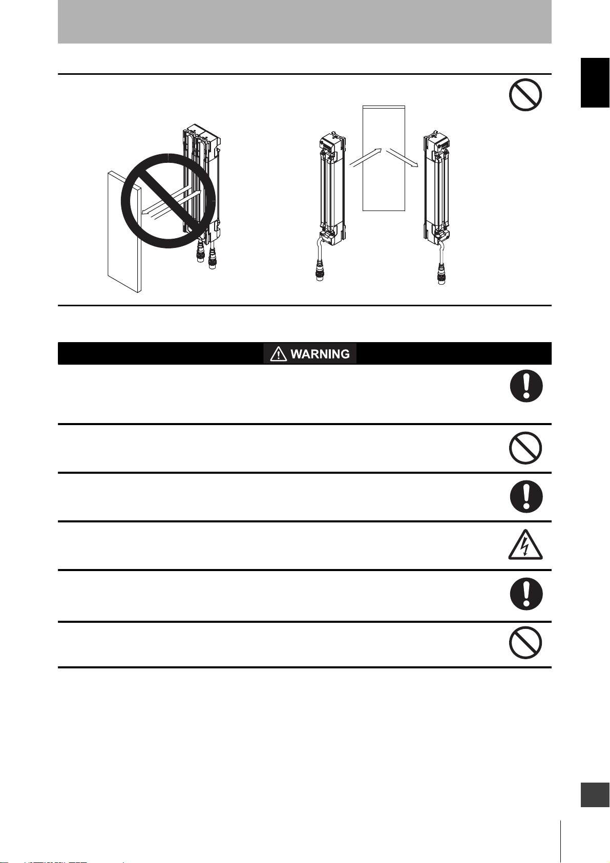
Do not use the F3SG-SR with mirrors in a retro-reflective configuration. Doing so may hinder
detection. It is possible to use mirrors to alter the detection zone to a 90-degree angle.
Mirror
Mirror
Introduction
Position with retro-reflection
Position with detection zone bent at 90°
Wiring
When using the PNP output, connect the load between the output and 0 V line. When using the
NPN output, connect the load between the output and +24 VDC line. Connecting the load
between the output and a different power supply line from the above line will result in a
dangerous condition because the operation mode of safety outputs are reversed to "Dark-ON".
When using the PNP output, do not ground +24 VDC line. When using the NPN output, do not
ground 0 V line. Otherwise, a ground fault may turn the safety outputs ON, resulting in a failure of
stopping the machine.
Configure the system by using the optimal number of safety outputs that satisfy the requirements
of the necessary safety category.
Do not connect each line of the F3SG-SR to a DC power supply of higher than 24 VDC+20%.
Also, do not connect it to an AC power supply. Failure to do so may result in electric shock.
Make sure to perform wiring while the power supply is OFF.
Do not use the output signal of the auxiliary output or IO-Link output for safety applications.
Failure to do so may result in serious injury when the F3SG-SR fails.
F3SG-SR
User’s Manual
E
ix
Page 12
Introduction
For the F3SG-SR to comply with IEC 61496-1 and UL 508, the DC power supply unit must
satisfy
all of the following conditions:
• The DC power supply operates within the rated power voltage (24 VDC ± 20%).
• The DC power supply has tolerance against the total rated current of devices if it is connected
to multiple devices.
• The DC power supply complies with EMC directives (industrial environment).
• Double or reinforced insulation is applied between the primary and secondary circuits.
• The DC power supply has an automatic recovery type of overcurrent protection characteristics.
• Output holding time is 20 ms or longer.
• The DC power supply satisfies output characteristic requirements for class 2 circuit or limited
voltage current circuit defined by UL 508. Refer to 5-4-2. Power Supply Unit.
• The DC power supply complies with laws and regulations, regarding EMC and electrical
equipment safety, of the country or region where the F3SG-SR is used. (For example, in EU,
the power supply must comply with the EMC Directive and the Low Voltage Directive.)
Double or reinforced insulation from hazardous voltage must be applied to all input and output
lines. Failure to do so may result in electric shock.
Extension of the cable must be within a specified length. If it isn't, safety functions may not work
properly, resulting in danger.
Settings
Make sure the Responsible Person tests the operation of the F3SG-SR after setting with the DIP
Switch on the F39-SGIT-IL3, Teach-in, SD Manager 3 or End Cap to verify that the F3SG-SR
operates as intended. Make sure to stop the machine until the test is complete. Unintended
settings may cause a person to go undetected, resulting in serious injury.
When performing the Backup, make sure to set the DIP Switch Position 1 at OFF (Unlock) before
turning on the power. If the DIP Switch Position 1 is at ON (Lock), the Restoration is performed,
which may case the settings of the F3SG-SR to be overwritten and a person to go undetected,
resulting in serious injury.
When performing the Restoration, make sure to set the DIP Switch Position 1 at ON (Lock)
before turning on the power. If the DIP Switch Position 1 at OFF (Unlock), the Backup is
performed, which may cause the settings of the Intelligent Tap to be overwritten and a person to
go undetected, resulting in serious injury.
When the Restoration is performed, if the DIP Switch Position 2 is at ON (DIP Switch Enabled)
and settings of the DIP Switch Positions 3 to 8 are different from the backup data in the F39SGIT-IL3, the settings in the DIP Switch takes priority and are saved in the F3SG-SR. To prevent
such an accident, it is recommended that you set the DIP Switch Position 2 at OFF before
performing the Restoration when you use the settings backed up from the F3SG-SR or make
settings with the SD Manager 3.
When pairing your device with the F39-SGBT Bluetooth® Communication Unit, make sure that
the model name and serial number of the sensor to be configured match the information on your
device.
F3SG-SR
x
User’s Manual
Page 13
Do not use the F39-SGBT Bluetooth® Communication Unit in close proximity to medical
equipment such as a pacemaker. Radio wave may affect the operation of such equipment.
Other
Perform daily and 6-month inspections for all F3SG-SR as described in Chapter 7 Checklists.
When using the F3SG-SR in cascade connection, perform inspections for every connected
F3SG-SR. Otherwise, the system may fail to work properly, resulting in serious injury.
Do not try to disassemble, repair, or modify the product. Doing so may cause the safety functions
to stop working properly.
Do not use the product in environments where flammable or explosive gases are present. Doing
so may result in explosion.
Do not use the F3SG-SR in environments where strong electromagnetic field may be produced.
Doing so may cause the safety functions to stop working properly.
Introduction
F3SG-SR
User’s Manual
E
xi
Page 14

Introduction
Make sure to observe the following precautions that are necessary for ensuring safe use of the product.
• Do not install, use, or store the product in the following types of environments:
• Do not drop the product.
• The rated life of the LEDs used for this product is 6 years.
• Loads must satisfy both of the following conditions:
• Make sure that the mounting brackets, fixing screws and connectors are properly secured with the torque
recommended in this document.
• Bending radii of cables must be equal to or higher than specified minimum values.
• When replacing the cables with those other than the dedicated cables, use cable connectors that provide a
protection grade of IP54 or higher, for the cables..
• To extend a cable length with a cable other than the dedicated cable, use a cable with the same or superior
specifications.
Precautions for Safe Use
- Areas exposed to intense interference light, such as direct sunlight
- Areas with high humidity where condensation is likely to occur
- Areas where corrosive gases are present
- Areas exposed to vibration or shock levels higher than in the specification provisions
- Areas where the pollution degree is harsher than 3, such as outdoor environment
- Areas where the product may get wet with liquid that can solve adhesive
- Not short-circuited
- Not used with a current that is higher than the rating
Refer to 5-4-3-10. Extending Cable Length with Commercially Available Cable
• Be sure to route the input/output lines for the F3SG-SR separate from high-potential power lines or through
an exclusive conduit.
• Make sure that foreign material such as water, oil, or dust does not enter the F3SG-SR, F39-SGIT-IL3 or the
connector while the end cap and root cables of the F3SG-SR or the cover of the DIP Switch on the F39SGIT-IL3 is removed.
• Make sure that foreign material such as water, oil, or dust does not enter the F39-SGBT or the connector
while the F39-SGBT is not connected to the F39-SGIT-IL3.
• The F39-SGIT-IL3 is dedicated to the F3SG-SR series. Do not use it for equipment other than F3SG-SR
series.
• In environments where foreign material such as spatter adheres to the F3SG-SR, attach a cover to protect
the F3SG-SR from the spatter.
• Some cutting oils may affect the product. Before using cutting oils, make sure that the oils should not cause
deterioration or degradation of the product.
• Do not use the product with degraded protective structure such as swelling and crack in housing and/or
sealing components. Otherwise cutting oil or other substance may enter the product, resulting in a risk of
corruption or burning.
• Use the F39-JGC- Root-Straight Cables, F39-JGR3K- Root-Plug Cables for Extended or F39-JGR3K- Conversion Cables and/or F39-JGR3W Cascading Cables for Extended or F39-JGR12L Side-byside Cascading Cables in environment where the product may be exposed to oil. Using the other cables in
such an environment may cause cutting oils or other substances to enter the cables, resulting in a risk of
damaging or burning the product.
• Do not connect the Conversion Cable for the following purposes. Failure to do so may result in failure.
1. Connecting with the F39-SGIT-IL3, F39-GCNY2 or F39-GCNY3
2. Connecting between the F3SG-SR's
• Dispose of the product in accordance with the relevant rules and regulations of the country or area where the
product is used.
xii
F3SG-SR
User’s Manual
Page 15

Precautions for Correct Use
Observe the precautions described below to prevent operation failure, malfunctions, or undesirable effects on
product performance.
Storage conditions and installation environment
• Do not install, use, or store the product in the following types of environments:
- Areas with a temperature or humidity out of the specified range
- Areas submerged in water or subject to rain water
• This is a class A product (for industrial environments). In residential areas it may cause radio
interference, in which case the Responsible Person may be required to take adequate measures to
reduce interference.
Wiring and installation
• Properly perform the wiring after confirming the signal names of all the terminals.
• Do not operate the control system until 3 s or more after turning ON the power of the F3SG-SR.
• When using a commercially available switching regulator power supply, make sure to ground the PE
terminal (protective earth terminal).
• Install the emitter and receiver to the same vertical direction.
• Use brackets of specified quantities and locations according to the dimensions. If the brackets
described above are not used, ratings and performance cannot be met.
• Do not install the F3SG-SR close to a device that generates high-frequency noise. Otherwise, take
sufficient blocking measures.
• Sharing the power supply with other devices may cause the F3SG-SR to be affected by noise or
voltage drop. It is recommended that the F3SG-SR use a power supply dedicated for safety
components, not shared with other devices.
• Do not change the scan code during normal operation. The F3SG-SR transitions to lockout.
• Do not apply load to the connectors.
• The operating range of the safety light curtain attached with the spatter protection cover is 10%
shorter than the rating. Install the product in consideration with the decrease of the operating range.
Cleaning
• Do not use thinner, benzene, or acetone for cleaning. They affect the product's resin parts and paint
on the housing.
• Use a soft cloth which is dry or wetted with clean water for cleaning. Do not use solvents.
Object detection
• The F3SG-SR cannot detect transparent and/or translucent objects.
Settings
• Do not operate the DIP Switch on the F39-SGIT-IL3 during normal operation of the F3SG-SR.
Otherwise, the F3SG-SR enters the LOCKOUT state.
• Do not operate the DIP Switch and Push Switch on the F39-SGIT-IL3 with tools that may damage the
product.
• Be sure that the F3SG-SR is in the SETTING state when making a change to the setting.
For more information on the SETTING state, refer to SETTING State under 2-2-1. Operating States of F3SG-SR and
Intelligent Tap.
Introduction
F3SG-SR
User’s Manual
E
xiii
Page 16

Introduction
Bluetooth® wireless technology
• The F39-SGBT Bluetooth® Communication Unit uses radio band of 2.4 GHz. The use of the product in
close proximity to the following examples of radio interference sources may cause radio interference
with the product, resulting in loss of or slow connection. Check the radio wave environment in your site
before installing the F39-SGBT.
Examples:
- Medical equipment such as a pacemaker
- RFID premises radio stations (license required) used in factory manufacturing lines
- Specified low power radio station
- Wireless LAN device
• When you use a PC, smartphone or tablet for Bluetooth® communication with the F39-SGBT, the
transmission distance may be shorter depending on structures of premises or obstructions. The
transmission may be interrupted especially by reinforced concrete.
- Use the product within the line of sight of 10 m.
- Use the product in conjunction with a Bluetooth device. It is not guaranteed that the product can
communicate with all Bluetooth devices.
xiv
F3SG-SR
User’s Manual
Page 17

Visual Aids
The following symbols appear in this document to help you locate different types of information.
Indicates important information or advice on a function or operation of the product.
Indicates page numbers or chapter title of related information.
Introduction
F3SG-SR
User’s Manual
E
xv
Page 18

Introduction
xvi
F3SG-SR
User’s Manual
Page 19

Table of Contents
Legislation and Standards i
Terms and Conditions Agreement iii
Terms and Conditions Agreement (Software) v
Safety Precautions vi
Precautions for Safe Use xii
Precautions for Correct Use xiii
Visual Aids xv
Chapter1 Overview and Specifications 1
1-1. What is Included 2
1-2. System Components 3
1-3. List of Key Features 5
1-3-1. Model Overview 5
1-3-2. List of Key Features 7
Introduction
1-4. LED Indicators on F3SG-SR 8
1-5. Ratings and Specifications 12
1-5-1. F3SG-SR Series 12
1-5-2. Intelligent Tap 19
1-5-3. Bluetooth® Communication Unit 20
1-6. List of Models 21
1-6-1. List of Models and Response Times 21
1-6-1-1. F3SG-SR 21
1-6-2. List of Models, Current Consumption and Weight 24
1-6-2-1. F3SG-SR 24
1-6-3. Calculation of Response Time of Cascaded Segments 28
Chapter2 System Operation and Functions 29
2-1. Combination of Functions 31
2-2. Operating States 33
2-2-1. Operating States of F3SG-SR and Intelligent Tap 33
2-2-2. Operating States of Intelligent Tap 34
2-3. Mutual Interference Prevention 35
2-3-1. Mutual Interference Prevention of F3SG-SR 35
2-3-1-1. Optical Synchronization 35
2-3-1-2. Wired Synchronization 38
2-4. PNP/NPN Selection 39
2-4-1. Overview 39
2-4-2. Setting with Intelligent Tap 39
2-4-3. Setting with SD Manager 3 39
F3SG-SR
User’s Manual
E
xvii
Page 20

Introduction
2-5. Self-Test 40
2-5-1. Overview 40
2-5-1-1. Self-Test details 40
2-5-1-2. Waveform of safety outputs 41
2-6. External Test 42
2-6-1. Overview 42
2-6-2. Factory Default Setting 43
2-6-3. Setting with Intelligent Tap 43
2-6-4. Setting with SD Manager 3 43
2-7. Lockout Reset 44
2-8. Interlock 45
2-8-1. Over view 45
2-8-2. Factory Default Setting 47
2-8-3. Setting with Intelligent Tap 47
2-8-4. Setting with SD Manager 3 47
2-9. Pre-Reset 48
2-9-1. Overview 48
2-9-2. Factory Default Setting 49
2-9-3. Setting with Intelligent Tap 50
2-9-4. Setting with SD Manager 3 50
2-10. PSDI 51
2-10-1.Overview 51
2-10-2.Factory Default Setting 53
2-10-3.Setting Change using Intelligent Tap 53
2-10-4.Setting Change using SD Manager 3 53
2-11. External Device Monitoring (EDM) 54
2-11-1.Overview 54
2-11-2.Factory Default Setting 55
2-11-3.Setting with Intelligent Tap 55
2-11-4.Setting with SD Manager 3 56
2-12. Auxiliary Output 57
2-12-1.Overview 57
2-12-2.Factory Default Setting 58
2-12-3.Setting with Intelligent Tap 58
xviii
2-12-4.Setting with SD Manager 3 59
2-13. Muting 61
2-13-1.Overview 61
2-13-2.Standard Muting Mode 63
2-13-2-1. Overview 63
2-13-2-2. Installation Example 1 of Standard Muting Mode (Using Two Muting Sensors) 66
2-13-3.Exit-Only Muting Mode 73
2-13-3-1. Overview 73
F3SG-SR
User’s Manual
Page 21

2-13-3-2. Installation Example of Exit-Only Muting Mode 75
2-13-4.Position Detection Muting Mode 78
2-13-4-1. Overview 78
2-13-4-2. Installation Example of Position Detection Muting Mode 80
2-13-5.Dynamic Muting 82
2-13-6.Factory Default Setting 83
2-13-7.Setting with Intelligent Tap 83
2-13-8.Setting with SD Manager 3 83
2-14. Override 85
2-14-1.Overview 85
2-14-2.Override at Normal Operation 86
2-14-3.Override upon Startup 88
2-14-4.Setting with Intelligent Tap 88
2-14-5.Setting with SD Manager 3 89
2-15. Fixed Blanking 90
2-15-1.Overview 90
Introduction
2-15-2.Factory Default Setting 94
2-15-3.Setting with Intelligent Tap 95
2-15-4.Setting with SD Manager 3 95
2-16. Floating Blanking 96
2-16-1.Overview 96
2-16-2.Factory Default Setting 100
2-16-3.Setting with Intelligent Tap 100
2-16-4.Setting with SD Manager 3 100
2-17. Reduced Resolution 101
2-17-1.Overview 101
2-17-2.Factory Default Setting 102
2-17-3.Setting with Intelligent Tap 102
2-17-4.Setting with SD Manager 3 103
2-18. Warning Zone 104
2-18-1.Overview 104
2-18-2.Factory Default Setting 107
2-18-3.Setting with Intelligent Tap 107
2-18-4.Setting with SD Manager 3 107
2-19. Setting Zone Adjacency Conditions 108
2-19-1.Zone Adjacency Condition 108
2-19-2.Zone Overlap Condition 108
2-20. Operating Range Selection 110
2-20-1.Overview 110
2-20-2.Factory Default Setting 111
2-20-3.Setting with Intelligent Tap 111
2-20-4.Setting with SD Manager 3 111
F3SG-SR
User’s Manual
E
xix
Page 22

Introduction
2-21. Response Time Adjustment 112
2-21-1.Overview 112
2-21-2.Factory Default Setting 112
2-21-3.Setting with Intelligent Tap 112
2-21-4.Setting with SD Manager 3 112
2-22. Area Beam Indicator (ABI) 113
2-22-1.Overview 113
2-22-2.Factory Default Setting 114
2-22-3.Setting Change using Intelligent Tap 114
2-22-4.Setting Change using SD Manager 3 114
2-23. Designated Beam Output 116
2-23-1.Overview 116
2-23-2.Factory Default Setting 116
2-23-3.Setting with Intelligent Tap 116
2-23-4.Setting with SD Manager 3 117
2-24. Stable Light Threshold Adjustment 118
2-24-1.Overview 118
2-24-2.Factory Default Setting 118
2-24-3.Setting Change using Intelligent Tap 118
2-24-4.Setting Change using SD Manager 3 118
2-25. Incident Light/Ambient Light 119
2-25-1.Incident Light Level Information 119
2-25-1-1. Overview 119
2-25-1-2. Setting with SD Manager 3 119
2-25-2.Ambient Light Level Information 119
2-25-2-1. Overview 119
2-25-2-2. Setting with SD Manager 3 119
2-26. Maintenance Information 120
2-26-1.Overview 120
2-26-2.Error Log 120
2-26-3.Warning Log 120
2-26-4.Power-ON Time 121
2-26-5.Load Switching Frequency 121
2-26-6.Muting Statistics Information 122
xx
2-26-7.Intelligent Tap Log 122
2-27. Operating Status Monitoring 123
2-27-1.Overview 123
2-27-2.Readout Information 123
2-28. Instantaneous Block Detection 124
2-28-1.Overview 124
2-28-2.Factory Default Setting 124
2-28-3.Setting Change using Intelligent Tap 124
F3SG-SR
User’s Manual
Page 23

2-28-4.Setting Change using SD Manager 3 124
2-29. Setting Recovery 125
2-30. Backup/Restoration 126
2-30-1.Overview 126
2-31. IO-Link 127
Chapter3 Setting with Intelligent Tap 129
3-1. List of Functions Configurable by Intelligent Tap and Initial Setup Method 130
3-1-1. Functions Configurable by Intelligent Tap 130
3-1-2. Initial Setup Method after Purchase 130
3-2. Connection 131
3-3. Wiring 132
3-4. LED Indicators on Intelligent Tap 133
3-5. DIP Switch on Intelligent Tap 134
3-6. Backup/Restoration 135
3-6-1. Description of Functions 135
Introduction
3-6-2. Performing Backup 136
3-6-3. Performing Restoration 138
3-6-4. Various Usage of Backup and Restoration 141
3-6-4-1. Plug and Work 141
3-6-4-2. Copy and Paste of Sensor Settings 141
3-6-4-3. Changing F3SG-SR Configuration to Connect to Intelligent Tap 141
3-6-4-4. Changing F3SG-SR's Settings with Intelligent Tap DIP Switch 141
3-7. Teach-in (Fix Blanking / Floating Blanking) 142
3-7-1. Setting Fixed Blanking by Teach-in 142
3-7-2. Setting Floating Blanking by Teach-in 146
3-8. Connection to SD Manager 3 150
3-9. IO-Link 151
3-9-1. Functional Description 151
3-9-2. Communication Specifications 151
3-9-3. Process Data 151
3-9-4. Service Data 153
Chapter4 Setting with SD Manager 3 157
4-1. Overview and Specifications 160
4-1-1. Overview of Configuration Tool 160
4-1-2. System Environment 161
4-1-2-1. PC Environment 161
4-1-2-2. Smartphone/Tablet Environment 161
4-1-3. Connection Method to Use Configuration Tools 162
F3SG-SR
User’s Manual
E
xxi
Page 24

Introduction
4-1-3-1. Connection Patterns of F3SG-SR, Intelligent Tap, and Each Device 162
4-1-3-2. Connection Procedure When Using USB Connector 164
4-1-3-3. Connection Procedure When Using Bluetooth® Communication Unit (F39-SGBT) 165
4-1-4. SETTING State of F3SG-SR with SD Manager 3 Connected 169
4-2. Basic Operation of SD Manager 3 170
4-2-1. How to Install/Uninstall SD Manager 3 170
4-2-1-1. Downloading SD Manager 3 170
4-2-1-2. Installing SD Manager 3 170
4-2-1-3. How to Uninstall SD Manager 3 172
4-2-1-4. Installing Driver of Intelligent Tap 173
4-2-2. How to Update SD Manager 3 173
4-2-3. Getting Started, Description on Top Page and Each Button, and Shutting Down 174
4-2-3-1. Getting Started 174
4-2-3-2. Description on Top Page and Each Button 175
4-2-3-3. Displaying/Hiding Docked Windows 177
4-2-3-4. Shutting Down 177
4-2-4. Starting SD Manager 3 Offline 178
4-2-4-1. Creating New Configuration File 178
4-2-4-2. Reading Configuration from PC 179
4-2-4-3. Saving New Configuration File to PC 179
4-2-4-4. Switching Offline to Online 179
4-2-5. Logging In/Logging Out 180
4-2-5-1. Logging In 180
4-2-5-2. Logging Out 182
4-2-6. Password Protection 183
4-2-6-1. Access Restriction 183
4-2-6-2. Changing Password 183
4-2-6-3. Forgot the Password? 183
4-2-6-4. Confirming Lot No. of Intelligent Tap 183
4-2-6-5. Resetting the Initial Password to “0000” 184
4-2-7. Reading/Saving/Writing Configuration of Intelligent Tap 185
4-2-7-1. Reading Configuration from Intelligent Tap 185
4-2-7-2. Saving Configuration of Intelligent Tap in PC 185
4-2-7-3. Writing Configuration into Intelligent Tap 186
xxii
4-2-8. Viewing Current Configuration 188
4-2-9. Safety Distance Calculation 189
4-3. Changing Settings with SD Manager 3 190
4-3-1. Preparing to Change Settings 190
4-3-2. I/O Settings 191
4-3-2-1. Interlock/External Device Monitoring (EDM)/PSDI 191
4-3-2-2. Reset Input Time 192
4-3-2-3. Teach-in Input 193
F3SG-SR
User’s Manual
Page 25

4-3-2-4. External Test Input 194
4-3-3. Auxiliary Output/Lamp Setting 195
4-3-3-1. Auxiliary Output 195
4-3-3-2. Designated Beam Output 197
4-3-3-3. Area Beam Indicator (ABI) 200
4-3-4. Safety Function Setting 202
4-3-4-1. Fixed Blanking 202
4-3-4-2. Floating Blanking 205
4-3-4-3. Muting/Override 207
4-3-4-4. Pre-Reset 212
4-3-4-5. Reduced Resolution 213
4-3-4-6. Warning Zone 214
4-3-4-7. PSDI 216
4-3-5. Operating State Setting 217
4-3-5-1. Response Time Change 217
4-3-5-2. Stable Light Threshold Adjustment 218
Introduction
4-3-5-3. Operating Range Selection 219
4-3-6. Setting Initialization 220
4-4. Monitoring with SD Manager 3 221
4-4-1. Monitoring 221
4-4-1-1. Incident Light/Ambient Light 221
4-4-1-2. Operating Status Monitoring 222
4-4-2. Muting Statistics Information 224
4-4-3. Maintenance Information 228
4-4-3-1. Error Log Information 228
4-4-3-2. Warning Log 230
4-4-3-3. Intelligent Tap Log 231
4-4-3-4. Power-On Time/Load Switching Frequency 232
4-4-3-5. Instantaneous Block Detection Information 234
4-5. Basic Operation of SD Manager 3 Mobile APP 235
4-5-1. How to Install/Uninstall SD Manager 3 Mobile APP 235
4-5-1-1. Installing SD Manager 3 Mobile APP 235
4-5-1-2. Uninstalling SD Manager 3 Mobile APP 235
4-5-2. How to Update SD Manager 3 Mobile APP 235
4-5-3. Pairing (Connection Verification) 235
4-5-4. Getting Started, Main Screen, Version Confirmation, and Shutting Down 237
4-5-4-1. Getting Started 237
4-5-4-2. Main Screen 239
4-5-4-3. Version Information 240
4-5-4-4. Shutting Down 241
4-5-5. Monitoring with SD Manager 3 242
4-5-5-1. Incident/Ambient Light Level Monitoring 242
F3SG-SR
User’s Manual
E
xxiii
Page 26

Introduction
4-5-5-2. Status Monitoring Information 243
4-5-5-3. Maintenance Information 245
Chapter5 Wiring and Installation 247
5-1. Installation Considerations 250
5-1-1. Detection Zone and Approach 250
5-1-2. Safety Distance 252
5-1-2-1. Safety Distance Formulas according to ISO 13855/EN ISO 13855 252
5-1-2-2. Safety Distance Formulas according to ANSI B11.19 256
5-1-3. Distance from Reflective Surfaces 257
5-1-3-1. F3SG-SR (Type 2 ESPE) 257
5-1-4. Mutual Interference Prevention 258
5-2. Dimensions 259
5-2-1. F3SG-SR Series 259
5-2-1-1. Mounted with Side-Mount Brackets (Intermediate Brackets) (F39-LSGF) 259
5-2-1-2. Mounted with Adjustable Side-Mount Brackets (Intermediate Brackets) (F39-LSGA) 261
5-2-1-3. Mounted with Adjustable Top/Bottom Brackets (F3SJ, F3SN Adapter) (F39-LSGTB-SJ)
and Side-Mount Brackets (Intermediate Brackets) (F39-LSGF) 263
5-2-1-4. Mounted with Adjustable Top/Bottom Brackets (F3SJ, F3SN Adapter) (F39-LSGTB-SJ)
and Adjustable Side-Mount Brackets (Intermediate Brackets) (F39-LSGA) 265
5-2-2. Bracket 267
5-2-2-1. Side-Mount Bracket (Intermediate Bracket) (F39-LSGF) 267
5-2-2-2. Adjustable Side-Mount Bracket (Intermediate Bracket) (F39-LSGA, sold separately)
267
5-2-2-3. Adjustable Top/Bottom Bracket (F3SJ, F3SN Adapter) (F39-LSGTB-SJ, sold separately)
267
5-2-2-4. Adjustable Top/Bottom Bracket (F3SG-RA/RE Adapter) (F39-LSGTB-RE, sold separate-
ly) 268
5-2-2-5. Adjustable Top/Bottom Bracket (MS4800, F3SR Adapter) (F39-LSGTB-MS, sold sepa-
rately) 268
5-2-3. Intelligent Tap 269
5-2-4. Intelligent Tap Bracket 269
5-2-5. Bluetooth® Communication Unit 271
5-2-6. Spatter Protection Cover 272
5-3. Mounting 273
xxiv
F3SG-SR
User’s Manual
5-3-1. Mounting Method 273
5-3-2. Number of Brackets Required 273
5-3-3. Proper Mounting 274
5-3-3-1. Proper Mounting Orientation 274
5-3-4. Mounting Procedure 276
5-3-4-1. Mounting with Side-Mount Brackets (Intermediate Brackets)
(F39-LSGF) 276
5-3-4-2. Mounting with Adjustable Side-Mount Brackets (Intermediate Brackets) (F39-LSGA) 277
Page 27

5-3-4-3. Mounting with Adjustable Top/Bottom Brackets (F3SJ, F3SN Adapter) (F39-LSGTB-SJ)
and Side-Mount Brackets (Intermediate Brackets) (F39-LSGF) 280
5-3-4-4. Mounting with Adjustable Top/Bottom Brackets (F3SJ, F3SN Adapter) (F39-LSGTB-SJ)
and Adjustable Side-Mount Brackets (Intermediate Brackets) (F39-LSGA) 284
5-3-5. Beam Alignment Procedure 289
5-4. Wiring 290
5-4-1. Wiring Precautions 290
5-4-2. Power Supply Unit 291
5-4-3. Cable Connections 292
5-4-3-1. Root-Straight Cable 292
5-4-3-2. Root-Plug Cable for Extended 293
5-4-3-3. Extended Socket-Straight Cable 294
5-4-3-4. Extended Plug-Socket Cable 295
5-4-3-5. Cascading Cable for Extended 297
5-4-3-6. Side-by-side Cascading Cable 298
5-4-3-7. F3SJ-B/A Conversion Cable 299
5-4-3-8. F3SG-RE Conversion Cable 301
Introduction
5-4-3-9. MS48 Conversion Cable 302
5-4-3-10. Extending Cable Length with Commercially Available Cable 303
5-4-3-11. Reduced Wiring Connector System with Y-Joint Plug/Socket Connector 304
5-4-3-12. Easy Wiring Connector System with Reset Switch Connector 305
5-4-4. Functional Earth Connection 307
5-5. Cascade Connection 308
5-5-1. Overview 308
5-5-2. Connection Procedure 310
Chapter6 Input/Output Circuit and Applications 313
6-1. Input/Output Circuit 314
6-1-1. Entire Circuit Diagram 314
6-1-2. Input Circuit Diagram by Function 315
6-2. Wiring Examples (for F3SG-SR) 316
6-2-1. Non-Muting System Wiring Examples 316
6-2-1-1. Auto Reset Mode with Optical Synchronization and EDM Unused 316
6-2-1-2. Auto Reset Mode with Wired Synchronization and EDM Unused 317
6-2-1-3. Auto Reset Mode with Optical Synchronization and EDM Used 318
6-2-1-4. Manual Reset Mode with EDM 319
6-2-1-5. Manual Reset Mode with EDM and Y-Joint Plug/Socket Connector 320
6-2-1-6. Manual Reset Mode with Intelligent Tap 321
6-2-1-7. Manual Reset Mode with Reset Switch Connector 322
6-2-1-8. Pre-Reset Mode with EDM Unused 323
6-2-1-9. Pre-Reset Mode with Reset Switch Connector 324
6-2-1-10. Single Break with EDM and Intelligent Tap 325
F3SG-SR
User’s Manual
E
xxv
Page 28

Introduction
Chapter7 Checklists 333
6-2-1-11. Double Break with EDM 326
6-2-2. Muting System Wiring Examples 327
6-2-2-1. Standard Muting Mode/Exit-Only Muting Mode 327
6-2-2-2. Standard Muting Mode/Exit-Only Muting Mode with Y-Joint Plug 328
6-2-2-3. Standard Muting Mode/Exit-Only Muting Mode with Intelligent Tap 329
6-2-2-4. Standard Muting Mode/Exit-Only Muting Mode with Reset Switch Connector 330
6-3. Connectable Safety Control Units 331
7-1. Pre-Operation Checklists 334
7-1-1. Checklists 334
7-1-1-1. Installation Condition Check 334
7-1-1-2. Wiring Check Before Power Is Turned ON 334
7-1-1-3. Operation Check While the Machine Is Stopped 335
7-1-1-4. Checking that Hazardous Parts Stop While the Machine Operates 336
7-2. Maintenance Checklists 337
7-2-1. Checklists 337
7-2-1-1. Inspection at Startup and When Changing Operators 337
7-2-1-2. Checking that Hazardous Parts Stop While the Machine Operates 338
7-2-1-3.
Items to Inspect Every 6 Months or When Machine Settings Are Changed 338
Chapter8 Appendix 341
8-1. Troubleshooting 342
8-1-1. LED Indicators (F3SG-SR) 342
8-1-2. LOCKOUT State 343
8-1-2-1. Description 343
8-1-2-2. Troubleshooting 344
8-1-3. Warning 349
8-1-3-1. Description 349
8-1-3-2. Troubleshooting 349
8-1-3-3. Muting Sequence Error Indication 350
8-1-3-4. Interlock Sequence Error Indication 351
8-1-3-5. PSDI Sequence Error Indication 352
xxvi
8-1-4. Troubleshooting for Intelligent Tap 353
8-1-5. Troubleshooting for Bluetooth® Communication Unit 356
8-2. Optional Accessories (Sold Separately) 357
8-3. Glossary 365
8-4. Revision History 369
F3SG-SR
User’s Manual
Page 29

Chapter 1 Overview and Specifications
1-1. What is Included 2
1-2. System Components 3
1-3. List of Key Features 5
1-3-1. Model Overview 5
1-3-2. List of Key Features 7
1-4. LED Indicators on F3SG-SR 8
1-5. Ratings and Specifications 12
1-5-1. F3SG-SR Series 12
1-5-2. Intelligent Tap 19
Chapter1 Overview and Specifications
1-5-3. Bluetooth® Communication Unit 20
1-6. List of Models 21
1-6-1. List of Models and Response Times 21
1-6-2. List of Models, Current Consumption and Weight 24
1-6-3. Calculation of Response Time of Cascaded Segments 28
F3SG-SR
User’s Manual
E
1
Page 30

Overview and Specifications
1-1. What is Included
Chapter1 What is Included
Before use, confirm that the items below are included with the product.
If you find that an item is missing, please contact your Omron representative.
F3SG-SR series
• Emitter 1
• Receiver 1
• Side-Mount Bracket (Intermediate Bracket) (F39-LSGF)*
• End Cap (for switching Scan Code Selection function) x 2 (End cap for Scan Code B is included.)
• Instruction Sheet x 7
• Quick Installation Manual x 1
• Troubleshooting Guide Sticker x 2
• Warning Zone Label x 1
* The quantity varies depending on the protective height.
Protective height of 0160 to 1440: 2 sets (total 4 pcs), 1520 to 2480: 3 sets (total 6 pcs)
F3SG-SR
2
User’s Manual
Page 31

1-2. System Components
-
5
4
-
Overview and Specifications
This section describes the system components and part names of the F3SG-SR system.
F3SG-SR series
Emitter
Beam
Indicator
Root cable
(Gray)
Extension cable
Beam center-line mark
Receiver
Root cable
(Black)
Marking on the side (Emitter)
-L
F3SG
“EMITTER” mark
Functional earth terminal on backside
· The marking "EMITTER" is on the side of emitter. And the marking
"RECEIVER" is on the side of receiver.
· The color of functional earth terminal screws is silver for the emitter and
black for the receiver.
Marking on the side (Receiver)
F3SG-
“RECEIVER” mark
Functional earth terminal
Chapter1 System Components
D
E
F3SG-SR
User’s Manual
3
Page 32

Overview and Specifications
F3SG-SR---
123 456
Appearance Model name Description
Chapter1 System Components
Emitter and receiver F3SG-4SR--- Select a model name based on the required protective height
and ESPE type.
The model name can be understood as follows:
1. ESPE type (4: Type 4 or 2: Type 2)*
2. Function (A: Advanced or B: Standard)
3. Protective height (mm)
4. Detection capability (14: 14 mm, 25: 25 mm, 45: 45 mm or 85:
85 mm)
5. L: emitter, D: receiver or blank: emitter and receiver
6. F: Flexible height model or blank
To distinguish between the emitter and receiver, find the word "EMITTER" or "Receiver" on the side of the F3SG-SR.
* Type 2 is not available in the Pan America’s.
F3SG-SR
4
User’s Manual
Page 33

1-3. List of Key Features
1-3-1. Model Overview
The F3SG-SR series is a safety light curtain intended to be used for humans protection.
F3SG-SR Series
The F3SG-SR series has two sub-series, F3SG-SRA and F3SG-SRB. Both are safety light curtains
comprising an emitter and a receiver.
The F3SG-SRA is a full-featured model having advanced functionality. The F3SG-SRB is a standard
model, yet it supports wide variety of functionality. The F3SG-SR series is suitable for finger, arm, leg
and body detection.
Intelligent Tap (F39-SGIT-IL3, sold separately)
The following setting functions are available by connecting the Intelligent Tap to the F3SG-SR.
(1) Setting with DIP Switch *1
(2) Setting with SD Manager 3 by connecting the Intelligent Tap to a PC *1
(3) Wireless communication with PC, smartphone or tablet by connecting the Intelligent Tap and
Bluetooth® Communication Unit (F39-SGBT, sold separately)
(4) IO-Link communication by connecting the Intelligent Tap and IO-Link Master
(5) Backup and Restoration of settings *2
Overview and Specifications
Chapter1 List of Key Features
*1. Refer to 1-3-2. List of Key Features for more information on configurable functions.
*2. Refer to Chapter 3 Setting with Intelligent Tap for more information on the Backup and Restoration.
(1)
Setting of F3SG-SR is possible with
DIP Switch on Intelligent Tap
DIP Switch
(3)
Bluetooth® communication
PC
BT
BT: Bluetooth
®
Communication Unit
(2)
USB
PC
Setting of F3SG-SR is possible
with SD Manager 3 via PC
(4)
Obtaining data is possible via IO-Link
communication by connecting IO-Link Master
IO-Link
Master
· PC: Setting is possible with SD Manager 3 via Bluetooth® communication
· Smartphone/Tablet: Monitoring is possible with SD Manager 3 Mobile APP
via Bluetooth
®
communication
F3SG-SR
User’s Manual
E
5
Page 34

Overview and Specifications
(5)
Chapter1 List of Key Features
<Backup>
F3SG-SR settings are backed up
to Intelligent Tap
<Restoration>
Settings saved in Intelligent Tap
are restored to F3SG-SR
<Plug and Work>
Settings backed up before F3SG-SR faults are
taken over to replaced F3SG-SR
<Copy and Paste>
Settings backed up in Intelligent Tap are
restored to multiple F3SG-SR's
NEW
F3SG-SR
6
User’s Manual
Page 35

Overview and Specifications
1-3-2. List of Key Features
The F3SG-SR has the following features. Some of the features are available or configurable by the
Intelligent Tap (F39-SGIT-IL3) or the SD Manager 3 (PC configuration tool). Sensor status monitoring
is available by the SD Manager 3 Mobile APP, which is the configuration tool for smartphones or
tablets.
Setting/Monitoring by
Availability
Feature
F3SG-
SRA
Mutual Interference
Prevention
PNP/NPN Selection X X X - - - - p.39
External Test X X X - - - - p.42
Interlock X X - - X X Auto Reset p.45
Pre-Reset X X - - X X Disabled p.48
PSDI X X - - - X Disabled p.51
External Device Monitoring
(EDM)
Auxiliary Output
Muting
Override X X - - - X Enabled p.85
Fixed Blanking X X - - X X Disabled p.90
Floating Blanking X X - - X X Disabled p.96
Reduced Resolution X X - - - X Disabled p.101
Warning Zone X X - - - X Disabled p.104
Operating Range Selection X X X - X X Long *5 p.110
Response Time Adjustment X X - - - X Normal p.112
Area Beam Indicator (ABI)
Designated Beam Output X X - - - X Disabled p.116
Stable Light Threshold
Adjustment
Light Level Monitoring X X - - - X - p.119
Maintenance Information X X - - - X - p.120
Operating Status Monitoring X X - - - X - p.123
Instantaneous Block
Detection Information
*1. DIP Switch is on the F39-SGIT-IL3 Intelligent Tap.
*2. The F39-SGIT-IL3 Intelligent Tap is necessary to use the SD Manager 3 or SD Manager 3 Mobile APP.
*3. Mutual interference can be prevented by Optical Synchronization or Wired Synchronization.
*4. Mutual interference can be prevented by Scan Code Selection.
*5. In the case of setting by DIP Switch or SD Manager 3. For the setting by wiring, it is selectable from the Long and Short modes.
F3SG-
SRB
XXX *3X *4- -
XX - - X X
XX - - - X
XX - - - X
X--- - X
XX - - - X
X--- - X
Sensor
Wiring
End
Cap
Intelligent
Tap
DIP
Switch
(*1)
PC /
Smartphone /
Tablet
SD Manager 3
SD Manager 3
Mobile APP (*2)
Factory default setting Page
Code A *4
Disabled
Safety output
information (Inverted
signal output: Enabled)
Enabled
(Standard Muting)
Block/Unblock
information
170%
Enabled
p.35
p.54
p.57
p.61
p.113
p.118
p.124
Chapter1 List of Key Features
F3SG-SR
User’s Manual
E
7
Page 36

Overview and Specifications
1-4. LED Indicators on F3SG-SR
Chapter1 LED Indicators on F3SG-SR
F3SG-SR Series
<Emitter>
F3SG-SR-14
F3SG-SR-25/-45/-85
7
15432
7
15432
6
6
<Receiver>
F3SG-SR-14
10
18432765
F3SG-SR-25/-45/-85
10
18432765
9
9
Shown below are indication statuses of the LED indicators on the F3SG-SR when you purchased.
F3SG-SR
8
User’s Manual
Page 37

Emitter (F3SG-SR)
Location Indicator Name Color Illuminated Blinking
Green Code A is selected
C
1 Scan code
2 Lockout Red
3
or
CODE
E
or
ERR
L
or
LONG
Operating
range
Orange Code B is selected
Automatic interference
prevention by wired
OFF
synchronization being
performed
LOCKOUT state. The
indicator is illuminated in
the emitter of another
sensor segment than that
having a lockout error
(when in cascade
connection or between the
emitter and receiver in the
Wired Synchronization)
Green
Long Mode is selected LOCKOUT state due to Operating
Short Mode is selected
OFF
LOCKOUT state. The indicator is
illuminated in the emitter of a sensor
segment having a lockout error
range selection setting error
Overview and Specifications
F3SG-
-XX
F3SG-
SRA
SRB
XX
XX
Chapter1 LED Indicators on F3SG-SR
T
4 Test Yellow -
5-
6 TOP
7 BTM
*1. The indicator of the emitter is illuminated only in the case the Wired Synchronization is enabled and is off in the case the
Optical Synchronization is enabled.
*2. Configurable by SD Manager 3.
*3. This is the case for the Standard Muting mode. For other muting modes, refer to "2-13. Muting".
*4. The Area Beam Indicator closer to the "TOP" mark on the F3SG-SR blinks.
*5. The Area Beam Indicator closer to the "BTM" mark on the F3SG-SR blinks.
*6. DIP switches is on the Intelligent Tap.
or
TEST
Area
Beam
Indicator
(ABI) (*1)
Top-beamstate (*1)
Bottombeamstate (*1)
Green
Orange
Red
OFF
Blue
Blue
The target beams of the
ABI are unblocked and
the safety outputs are
turned ON
Incident light level of
the target beams of the
ABI is 170% (factory
default setting (*2)) or
less of ON-threshold
(for 5 to 10 s)
The target beams of the
ABI are blocked
The target beams of the
ABI are unblocked (The
ABI then will be
illuminated in green
when the safety outputs
are turned ON.)
The top beam is
unblocked
The bottom beam is
unblocked
External Test is being performed
MUTING or OVERRIDE state. In the
MUTING state, only the ABI indicators
in the muting zone are blinking. Or the
target beams of the ABI are blocked
instantaneously
Incident light level of the target beams of
the ABI is 170% (factory default setting
(*2)) or less of ON threshold 5 to 10 s
after illuminated when incident light level
of the target beams of the ABI is 170%
(factory default setting (*2)) or less of ON
threshold. Or one muting input becomes
the ON state and the MUTING state has
not been started yet, or one muting input
becomes the OFF state and the other is
not in the OFF state yet. (*3)
LOCKOUT state due to Cap error or Other
sensor error (*4), or LOCKOUT state due
to DIP Switch setting error (*5 *6)
-
MUTING/OVERRIDE state, or
LOCKOUT state due to Cap error or
Other sensor error
MUTING/OVERRIDE, or LOCKOUT
state due to DIP Switch setting error (*6)
XX
X-
-X
-X
E
F3SG-SR
User’s Manual
9
Page 38

Overview and Specifications
Receiver (F3SG-SR)
Location Indicator Name Color Illuminated Blinking
Chapter1 LED Indicators on F3SG-SR
1 Scan code
CODE
2 Lockout Red
ERR
3 ON/OFF
OSSD
4
MAINT
5
PNP
C
or
E
or
O
or
M
or
P
or
Maintenance
PNP/NPN
mode
Green Code A is selected
Orange Code B is selected
Automatic interference
prevention by wired
OFF
synchronization being
performed
LOCKOUT state. The
indicator is illuminated in
the receiver of another
sensor segment than that
having a lockout error
(when in cascade
connection or between
the emitter and receiver
in the Wired
Synchronization)
Green
Orange
Green
Safety outputs are in ON
state
Safety outputs are in
Red
OFF state
LOCKOUT state due to a
recoverable error (When
in cascade connection,
Red
the indicator of only the
sensor segment having
the error is illuminated)
Safety outputs are
instantaneously turned
OFF due to ambient light,
vibration or noise.
Or sequence error in
Muting, Pre-Reset or
PSDI
PNP is configured Polarity of PNP is changed to NPN, or
NPN is configured
OFF
-XX
LOCKOUT state. The indicator is
illuminated in the receiver of a sensor
segment having a lockout error
-XX
LOCKOUT state due to Safety output
error, or error due to abnormal power
supply or noise
LOCKOUT state due to a
replacement-recommended error
(When in cascade connection, the
indicator of only the sensor segment
having the error blinks)
Intelligent Tap is in the LOCKOUT
state
vice versa, during operation, and
internal circuit is defective
F3SG-
F3SG-
SRA
SRB
XX
XX
XX
XX
XX
10
F3SG-SR
User’s Manual
F
6
7 Sequence Yellow
or
CFG
S
or
SEQ
Configuration
Green
Fixed or Floating
Blanking, Reduced
Resolution, Warning Zone
or Slow mode of
Response Time
Adjustment is enabled.
Or after the Muting zone
is determined by the
Dynamic Muting function.
INTERLOCK state Sequence or sequence error in
TEACH-IN mode, zone measurement
being performed by Dynamic Muting,
or LOCKOUT state due to Blanking
monitoring error, Configuration error
or Parameter error X X
Muting, Pre-Reset or PSDI (*1) or
Teach-in error
XX
Page 39

Overview and Specifications
Location Indicator Name Color Illuminated Blinking
The target beams of the
ABI are unblocked and
Green
Orange
Area
8-
9 TOP
10 BTM
*1. Refer to 8-1. Troubleshooting for more information on blinking patterns.
*2. Configurable by SD Manager 3.
*3. This is the case for the Standard Muting mode. For other muting modes, refer to 2-13. Muting.
*4. The Area Beam Indicator closer to the "TOP" mark on the F3SG-SR blinks.
*5. The Area Beam Indicator closer to the "BTM" mark on the F3SG-SR blinks.
*6. DIP switches is on the Intelligent Tap.
Beam
Indicator
(ABI)
Top-beamstate
Bottom-
beam-
state
the safety outputs are
turned ON
Incident light level of the
target beams of the ABI
is 170% (factory default
setting (*2)) or less of
ON-threshold (for 5 to 10
s)
The target beams of the
ABI are blocked
Red
The target beams of the
ABI are unblocked (The
ABI then will be
OFF
illuminated in green when
the safety outputs are
turned ON.)
The top beam is
Blue
unblocked
The bottom beam is
Blue
unblocked
MUTING or OVERRIDE state. In the
MUTING state, only the ABI
indicators in the muting zone are
blinking. Or the target beams of the
ABI are blocked instantaneously
Incident light level of the target
beams of the ABI is 170% (factory
default setting (*2)) or less of ON
threshold 5 to 10 s after illuminated
when incident light level of the target
beams of the ABI is 170% (factory
default setting (*2)) or less of ON
threshold. Or one muting input
becomes the ON state and the
MUTING state has not been started
yet, or one muting input becomes the
OFF state and the other is not in the
OFF state yet. (*3)
LOCKOUT state due to Cap error or
Other sensor error (*4), or LOCKOUT
state due to DIP Switch setting error
(*5 *6)
-
MUTING/OVERRIDE state, or
LOCKOUT state due to Cap error or
Other sensor error
MUTING/OVERRIDE state, or
LOCKOUT state due to DIP Switch
setting error (*6)
F3SG-
F3SG-
SRA
SRB
X-
-X
-X
Chapter1 LED Indicators on F3SG-SR
In the SETTING state to make settings with the SD Manager 3, the TEST, LONG and CODE indicators on the emitter
and the CFG, PNP and CODE indicators on the receiver blink.
(TEST: Yellow, LONG/CODE: Green, CFG/PNP/CODE: Green)
For more information on the statuses of the LED indicators in the SETTING state, refer to 4-1-4. SETTING State
of F3SG-SR with SD Manager 3 Connected.
F3SG-SR
User’s Manual
E
11
Page 40

Overview and Specifications
1-5. Ratings and Specifications
Chapter1 Ratings and Specifications
Extension of the cable must be within a specified length. If it isn't, safety functions may not work
properly, resulting in danger.
1-5-1. F3SG-SR Series
The in the model names indicate the protective heights in millimeters.
Model
Performance
Object resolution
(Detection capability)
Beam gap 10 mm 20 mm 40 mm 80 mm
Number of beams 15 to 199 8 to 124 6 to 38 4 to 12
Lens size
Protective height 160 to 2,000 mm 160 to 2,480 mm 240 to 1,520 mm 280 to 920 mm
Operating
range
Response time
F3SG-SRA-14
F3SG-SRB-14
Opaque objects
14-mm dia. 25-mm dia. 45-mm dia. 85-mm dia.
4.4 3.4 mm (W H) 6.7 4.5 mm (W H)
Long 0.3 to 10.0 m * 0.3 to 20.0 m
Short 0.3 to 3.0 m * 0.3 to 7.0 m
* When operating at an ambient temperature of -10 to -30°C, use the F3SG-SR with the operating range
of 0.3 to 5.0 m in Long Mode and 0.3 to 1.5 m in Short Mode.
*1Normal
mode
×2 Slow
mode *2
×4 Slow
mode *2
ON to
OFF
OFF
to ON
ON to
OFF
OFF
to ON
ON to
OFF
OFF
to ON
Optical
synchronization:
8 to 18 ms
Wired
synchronization:
10 to 21 ms
Optical
synchronization:
40 to 90 ms
Wired
synchronization:
50 to 105 ms
Optical
synchronization:
16 to 36 ms
Wired
synchronization:
20 to 42 ms
Optical
synchronization:
80 to 180 ms
Wired
synchronization:
100 to 210 ms
Optical
synchronization:
32 to 72 ms
Wired
synchronization:
40 to 84 ms
Optical
synchronization:
160 to 360 ms
Wired
synchronization:
200 to 420 ms
F3SG-SRA-25
F3SG-SRB-25
Optical
synchronization:
8 to 13 ms
Wired
synchronization:
10 to 17 ms
Optical
synchronization:
40 to 65 ms
Wired
synchronization:
50 to 85 ms
Optical
synchronization:
16 to 26 ms
Wired
synchronization:
20 to 34 ms
Optical
synchronization:
80 to 130 ms
Wired
synchronization:
100 to 170 ms
Optical
synchronization:
32 to 52 ms
Wired
synchronization:
40 to 68 ms
Optical
synchronization:
160 to 260 ms
Wired
synchronization:
200 to 340 ms
F3SG-SRA-45
F3SG-SRB-45
Optical synchronization: 8 ms
Wired synchronization: 10 ms
Optical synchronization: 40 ms
Wired synchronization: 50 ms
Optical synchronization: 16 ms
Wired synchronization: 20 ms
Optical synchronization: 80 ms
Wired synchronization: 100 ms
Optical synchronization: 32 ms
Wired synchronization: 40 ms
Optical synchronization: 160 ms
Wired synchronization: 200 ms
F3SG-SRA-85
F3SG-SRB-85
12
F3SG-SR
User’s Manual
Page 41

Overview and Specifications
Model
×8 Slow
mode *2
*1. Response time when used in one segment system.
See 1-6-1. List of Models and Response Times for more information.
*2. Selectable by SD Manager 3.
Effective
aperture angle
(EAA)
(IEC 61496-2)
Light source Infrared LEDs, Wavelength: 870 nm
Startup waiting time 3 s max.
Electrical Power supply voltage (Vs) SELV/PELV 24 VDC±20% (ripple p-p 10% max.)
Current consumption
Safety outputs (OSSD) Two PNP or NPN transistor outputs (PNP or NPN is selectable by wiring of power
Type 4 ±2.5° max. *
*Emitter and receiver at operating range of 3 m or greater
F3SG-SRA-14
F3SG-SRB-14
ON to
Optical
OFF
synchronization:
64 to 144 ms
Wired
synchronization:
80 to 168 ms
OFF
Optical
to ON
synchronization:
320 to 720 ms
Wired
synchronization:
400 to 840 ms
See 1-6. List of Models for more information.
supply.)
Load current: 300 mA max., Residual voltage: 2 V max. (except for voltage drop due to
cable extension), Capacitive load: 1 μF max., Inductive load: 2.2 H max. *1 *2 *3
Leakage current: 1 mA max.(PNP), 2 mA max.(NPN) *4
F3SG-SRA-25
F3SG-SRB-25
Optical
synchronization:
64 to 104 ms
Wired
synchronization:
80 to 136 ms
Optical
synchronization:
320 to 520 ms
Wired
synchronization:
400 to 680 ms
F3SG-SRA-45
F3SG-SRB-45
Optical synchronization: 64 ms
Wired synchronization: 80 ms
Optical synchronization: 320 ms
Wired synchronization: 400 ms
F3SG-SRA-85
F3SG-SRB-85
Chapter1
Ratings and Specifications
*1. For the F3SG-SRA, the load current is 150 mA max. in 2-segment cascade and
80 mA max. in 3-segment cascade.
*2. The residual voltage is 3 V max. when the Intelligent Tap is connected to the sensor.
*3. The load inductance is the maximum value when the safety output frequently
repeats ON and OFF.
When you use the safety output at 4 Hz or less, the usable load inductance
becomes larger.
*4. These values must be taken into consideration when connecting elements including
a capacitive load such as a capacitor.
Auxiliary output One PNP or NPN transistor output (PNP or NPN is selectable by wiring of power
supply.)
Load current: 100 mA max., Residual voltage: 2 V max. *
* The residual voltage is 3 V max. when the Intelligent Tap is connected to the sensor.
Output
operation
mode
Safety output Light-ON (Safety outputs are turned to the ON state when the receiver receives an
emitting signal.)
Auxiliary
output
Safety output (Inverted signal output: Enable) (default) (Configurable by SD Manager 3)
F3SG-SR
User’s Manual
E
13
Page 42

Overview and Specifications
Model
Input voltage TEST Light emission stops when connected to 24 VDC
Chapter1 Ratings and Specifications
Overvoltage category
(IEC 60664-1)
Indicators
Protective circuit Output short-circuit protection
Insulation resistance 20 M or higher (500 VDC megger)
Dielectric strength 1,000 VAC, 50/60 Hz (1 min)
Functional Mutual interference prevention Optical synchronization by Scan Code: in up to 2 sets
F3SG-SRA-14
F3SG-SRB-14
ON voltage: Vs-3 V to Vs (short circuit current: approx. 5.0 mA) *
OFF voltage: 0 V to 1/2 Vs, or open (short circuit current: approx. 6.0 mA) *
Light emission stops when connected to 0 V
ON voltage: 0 to 3 V (short circuit current: approx. 6.0 mA)
OFF voltage: 1/2 Vs to Vs, or open (short circuit current: approx. 5.0 mA) *
OPERATING
RANGE
SELECT
INPUT
RESET/EDM PNP
MUTE A/B ,
PRE-RESET,
PSDI
*The Vs indicates a supply voltage value in your environment.
Long: 12 V to Vs (short circuit current: approx. 4.2 mA) * or open
Short: 0 to 3 V (short circuit current: approx. 4.2 mA)
ON voltage: Vs-3 V to Vs (short circuit current: approx. 9.5 mA) *
OFF voltage: 0 V to 1/2 Vs, or open (short circuit current: approx. 13.0 mA) *
NPN
ON voltage: 0 to 3 V (short circuit current: approx. 13.0 mA)
OFF voltage: 1/2 Vs to Vs, or open (short circuit current: approx. 9.5 mA) *
PNP
ON voltage: Vs-3 V to Vs (short circuit current: approx. 4.5 mA) *
OFF voltage: 0 V to 1/2 Vs, or open (short circuit current: approx. 7.0 mA) *
NPN
ON voltage: 0 to 3 V (short circuit current: approx. 7.0 mA)
OFF voltage: 1/2 Vs to Vs, or open (short circuit current: approx. 4.5 mA) *
II
See F3SG-SR Series for more information.
Wired synchronization: in up to 3 sets
See 5-1-4. Mutual Interference Prevention for more information.
F3SG-SRA-25
F3SG-SRB-25
F3SG-SRA-45
F3SG-SRB-45
F3SG-SRA-85
F3SG-SRB-85
Cascade connection Number of cascaded segments: 3 max.
Total number of beams: 255 max.
Test function Self-test (at power-on, and during operation)
External test (light emission stop function by test input)
Safety-related functions Interlock
External Device Monitoring (EDM)
Pre-Reset
PSDI
Fixed Blanking/Floating Blanking
Reduced Resolution
Muting/Override
Mutual Interference Prevention
PNP/NPN Selection
Response Time Adjustment
See Chapter 2 System Operation and Functions and Chapter 3 Setting with
Intelligent Tap for more information.
14
F3SG-SR
User’s Manual
Page 43

Overview and Specifications
Model
Environmental
Connections Root cable Type of
Ambient
temperature
Ambient
humidity
Ambient illuminance Incandescent lamp: 3,000 Ix max. on receiver surface
Degree of protection
(IEC 60529)
Vibration resistance
(IEC 61496-1)
Shock resistance
(IEC 61496-1)
Pollution degree
(IEC 60664-1)
Cascading
cable
Extension
cable
- Extended
SocketStraight
Cable
- Extended
Plug-Socket
Cable
Operating -30 to 55 °C (non-icing)
Storage -30 to 70 °C
Operating 35% to 85% (non-condensing)
Storage 35% to 95%
connection
Number of
wires
Cable length See 5-4-3-1. Root-Straight Cable and 5-4-3-2. Root-Plug Cable for Extended
Cable
diameter
Minimum
bending radius
Type of
connection
Number of
wires
Cable length
Cable
diameter
Minimum
bending radius
Type of
connection
Number of
wires
Cable length
Cable
diameter
Minimum
bending radius
F3SG-SRA-14
F3SG-SRB-14
Sunlight: 10,000 Ix max. on receiver surface
IEC 60529: IP65 and IP67, JIS C 0920 Annex 1: IP67G
10 to 55 Hz, Multiple amplitude of 0.7 mm, 20 sweeps for all 3 axes
100 m/s2, 1000 shocks for all 3 axes
3
To sensors: dedicated connector, To external: M12 connector type (5-pin emitter and 8pin receiver) or open-ended type
IP67 and IP67G (JIS C 0920 Annex 1) * rated when mated.
* The F3SG-SR meets the degree of protection when the root cable is correctly
connected with the F3SG-SR. The degree of protection is not satisfied with the part
where cable wires are uncovered.
Emitter: 5, Receiver: 8
for more information.
6 mm
R5 mm
To sensors: dedicated connector, To cascading sensors: M12 connector type (5-pin
emitter and 8-pin receiver) or dedicated connector
IP67 and IP67G (JIS C 0920 Annex 1) * rated when mated.
* The F3SG-SR meets the degree of protection when the cascading cable is correctly
connected with the F3SG-SR and the root cable.
Emitter: 5, Receiver: 8
See 5-4-3-5. Cascading Cable for Extended for more information.
6 mm
R5 mm
M12 connector type (5-pin emitter and 8-pin receiver), IP67* rated when mated
The extension cable meets the degree of protection when the root cable is correctly
connected with the extension cable.The degree of protection is not satisfied with the
part where cable wires are uncovered.
Emitter: 5, Receiver: 8
See 5-4-3-3. Extended Socket-Straight Cable and 5-4-3-4. Extended Plug-
Socket Cable for more information.
6.6 mm
R36 mm
F3SG-SRA-25
F3SG-SRB-25
F3SG-SRA-45
F3SG-SRB-45
F3SG-SRA-85
F3SG-SRB-85
Chapter1 Ratings and Specifications
F3SG-SR
User’s Manual
E
15
Page 44

Overview and Specifications
Model
Chapter1 Ratings and Specifications
Connections Cable
extension
Material Housing: Aluminum alloy
Weight
Included accessories Instruction Sheet, Quick Installation Manual, Troubleshooting Guide Sticker, Warning
Conformity Conforming standards
Type of ESPE (IEC 61496-1) F3SG-4SR-: Type 4
Performance Level
(PL)/Safety category
PFHD F3SG-SR-: 1.1×10⁻⁸ max. (IEC 61508)
Proof test interval TM Every 20 years (IEC 61508)
SFF 99% (IEC 61508)
HFT 1 (IEC 61508)
Classification Type B (IEC 61508-2)
See the section following this table for the restrictions on cable extension.
Root cable In optical synchronization: 100 m max* between power supply and emitter and
Cascade
connection
F3SG-SRA-14
F3SG-SRB-14
between power supply and receiver
In wired synchronization: 100 m max* between power supply and emitter, between
power supply and receiver, and between emitter and receiver
* When the Intelligent Tap (F39-SGIT-IL3) is connected to the sensor, this applies in the
case of the rated power supply of 24 VDC to 24 VDC +20%.
Extension cable between sensors: 10 m max. (not including Cascading Cable for
Extended*1 and Root Cable*2.)
*1. F39-JGR3W
*2. F39-JGR3K
Cap: PBT resin
Front window: Acrylic resin
Side-Mount Bracket (Intermediate Bracket)(F39-LSGF): Zinc alloy
FE plate: Stainless steel
See 1-6-2. List of Models, Current Consumption and Weight for more
information.
Zone Label, End Cap (for switching Scan Code Selection function), Side-Mount
Bracket (Intermediate Bracket) (F39-LSGF)*
*The quantity varies depending on the protective height.
Protective height of 0160 to 1440: 2 sets (total 4 pcs), 1520 to 2480: 3 sets (total 6
pcs)
See Legislation and Standards for more information.
F3SG-4SR-: PL e/Category 4 (EN ISO 13849-1:2015)
F3SG-SRA-25
F3SG-SRB-25
F3SG-SRA-45
F3SG-SRB-45
F3SG-SRA-85
F3SG-SRB-85
16
F3SG-SR
User’s Manual
Page 45

Restrictions on cable extension
- Wired synchronization
* Not including Cascading Cable for Extended (F39-JGR3W) and Root Cable (F39-JGR3K).
- Optical synchronization
Emitter
Receiver
Maximum extionsion length
(1) to (4): 10 m each *
(5) to (6): 100 m each
(1)
(2)
(3)
(4)
(5)
(6)
Emitter
Receiver
(1)
(2)
(3)
(4)
(5)
(6)
Maximum extionsion length
(1) to (4): 10 m each *
(5) to (6): 100 m each
Power
supply
Power
supply
Power
supply
(5)
(6)
(8)*2
(7)
Emitter
Receiver
(1)
(2)
(3)
(4)
Power
supply
IO-Link
master
- Wired synchronization
The cable extension must satisfy all the following conditions.
<Intellingent Tap not used>
Overview and Specifications
Chapter1 Ratings and Specifications
<Intellingent Tap used>
Maximum cable extension (Load condition: Safety outputs 1 and 2: 60 mA, Auxiliary output: 60 mA)
Sensor F3SG-SRA *1 *3 F3SG-SRB *1 *3
Cascading Single 2-segment *4 3-segment *4 Single 2-segment 3-segment
(1),(2),(3),(4) 10 m each *5 10 m each *5
(5)+(7)
(6)+(7)
*1. Cable extension when (5) and (6) are 10 m each
*2. (8) must be 20 m max.
*3. Under the maximum load conditions (safety outputs 1 and 2 of 300 mA per channel and auxiliary output of 100 mA), the cable
extension must be 50% max. of the length listed in the table for the F3SG-SRA and 80% max. for the F3SG-SRB.
*4. Conditions exist for the use of the F3SG-SRA in 2-segment or 3-segment cascade. Refer to 1-5-1. F3SG-SR Series –
Electrical – Safety outputs (OSSD).
*5. Not including the Cascading Cable for Extended (F39-JGR3W) and the Root-Plug Cable for Extended (F39-JGR3K).
≤ 100 m ≤ 70 m ≤ 60 m ≤ 100 m ≤ 95 m ≤ 70 m
F3SG-SR
User’s Manual
E
17
Page 46

Chapter1 Ratings and Specifications
(5)
(6)
Emitter
Receiver
(1)
(2)
(3)
(4)
Power
supply
(8)*2
(7)
Power
supply
IO-Link
master
- Optical synchronization
(5)
(6)
Emitter
Receiver
Y-Joint Plug/
Socket Connector
(F39-GCNY2)
L = 100 to 60 m
(1)
(2)
(3)
(4)
(7)
Power
supply
Overview and Specifications
Maximum cable extension (Load condition: Safety outputs 1 and 2: 60mA, Auxiliary output : 60 mA)
Sensor F3SG-SRA *1 *3 F3SG-SRB *1 *3
Cascading Single 2-segment *4 3-segment *4 Single 2-segment 3-segment
(1),(2),(3),(4) 10 m each *5 10 m each *5
(5) 100 m 100 m
(6)+(7) ≤ 100 m ≤ 100 m ≤ 80 m ≤ 100 m ≤ 100m ≤ 100 m
*1. Cable extension when (6) is 10 m
*2. (8) must be 20 m max.
*3. Under the maximum load conditions (safety outputs 1 and 2 of 300 mA per channel and auxiliary output of 100 mA), the cable
extension must be 50% max. of the length listed in the table for the F3SG-SRA and 80% max. for the F3SG-SRB.
*4. Conditions exist for the use of the F3SG-SRA in 2-segment or 3-segment cascade. Refer to 1-5-1. F3SG-SR Series –
Electrical – Safety outputs (OSSD).
*5. Not including the Cascading Cable for Extended (F39-JGR3W) and the Root-Plug Cable for Extended (F39-JGR3K).
<Using Y-Joint Plug/Socket Connector (F39-GCNY2)>
Maximum cable extension (Load condition: Safety outputs 1 and 2: 60mA, Auxiliary output : 60 mA)
Sensor F3SG-SRA *1 *2 F3SG-SRB *1 *2
Cascading Single 2-segment *3 3-segment *3 Single 2-segment 3-segment
(1),(2),(3),(4) 10 m each *4 10 m each *4
L: (5)+(7)
(6)+(7)
*1. Cable extension when (5) and (6) are 10 m each
*2. Under the maximum load conditions (safety outputs 1 and 2 of 300 mA per channel and auxiliary output of 100 mA), the cable
extension must be 50% max. of the length listed in the table for the F3SG-SRA and 80% max. for the F3SG-SRB.
*3. Conditions exist for the use of the F3SG-SRA in 2-segment or 3-segment cascade. Refer to 1-5-1. F3SG-SR Series –
Electrical – Safety outputs (OSSD).
*4. Not including the Cascading Cable for Extended (F39-JGR3W) and the Root-Plug Cable for Extended (F39-JGR3K).
≤ 100 m ≤ 70 m ≤ 60 m ≤ 100 m ≤ 90 m ≤ 80 m
F3SG-SR
18
User’s Manual
Page 47

Overview and Specifications
1-5-2. Intelligent Tap
Model F39-SGIT-IL3
Applicable sensor
Performance
Electrical Power supply voltage (Vs) Supplied from external power source: SELV/PELV 24 VDC±20% (ripple p-p 10% max.)
Response time Output ON to OFF and OFF to ON: 44 ms max. each *
Startup waiting time 3 s max.
Current consumption 85 mA max. (When connecting 24 VDC power supply and IO-Link Master)
Safety outputs (OSSD)/
Auxiliary output
F3SG-SR Series
*The response time is the time interval between the changes of the states of the sensor
OSSD's and the DO (pin 2).
USB bus powered: 5 VDC
Refer to the ratings and specifications of the F3SG-SR. The safety outputs and
auxiliary output of the Intelligent Tap are directly connected to those of the F3SG-SR.
See 1-5-1. F3SG-SR Series for more information.
Chapter1 Ratings and Specifications
Digital output for pin 2
(IO-Link) *
*For the DO (pin 2) of CN3
Input voltage RESET, EDM PNP
MUTE A/B,
PRE-RESET,
PSDI *1
*1. PSDI is only available for F3SG-SR.
*2. The Vs indicates a supply voltage value in your environment.
Overvoltage category
(IEC 60664-1)
Protective circuit Output short-circuit protection, Output reverse polarity protection
Insulation resistance 20 M or higher (500 VDC megger)
Dielectric strength 1,000 VAC, 50/60 Hz (1 min)
Functional Maintenance Information Error Log
One PNP transistor output
Load current: 100 mA max., Residual voltage: 2 V max., Leakage current: 1 mA max.
The DO is in the OFF state when the safety outputs are in the ON state. The DO is in
the ON state when the safety outputs are in the OFF state. (Regardless of the PNP/
NPN setting of the F3SG-SR)
ON voltage: Vs-3 V to Vs (short circuit current: approx. 9.5 mA) *2
OFF voltage: 0 V to 1/2 Vs, or open (short circuit current: approx. 13.0 mA) *2
NPN
ON voltage: 0 to 3 V (short circuit current: approx. 13.0 mA)
OFF voltage: 1/2 Vs to Vs, or open (short circuit current: approx. 9.5 mA) *2
PNP
ON voltage: Vs-3 V to Vs (short circuit current: approx. 4.5 mA) *2
OFF voltage: 0 V to 1/2 Vs, or open (short circuit current: approx. 7.0 mA) *2
NPN
ON voltage: 0 to 3 V (short circuit current: approx. 7.0 mA)
OFF voltage: 1/2 Vs to Vs, or open (short circuit current: approx. 4.5 mA) *2
II
Power-ON Time
See 2-26. Maintenance Information for more information.
Environmental
Ambient
temperature
Ambient
humidity
Degree of protection
(IEC 60529)
Vibration resistance
(IEC 61496-1)
Shock resistance
(IEC 61496-1)
Pollution degree
(IEC 60664-1)
Operating -30 to 55 °C (non-icing)
Storage -30 to 70 °C
Operating 35% to 85% (non-condensing)
Storage 35% to 85%
IP65, IP67 and IP67G (Covers and cables connected with the Intelligent Tap.)
10 to 55 Hz, Multiple amplitude of 0.7 mm, 20 sweeps for all 3 axes
100 m/s2, 1000 shocks for all 3 axes
3
F3SG-SR
User’s Manual
E
19
Page 48

Overview and Specifications
Model F39-SGIT-IL3
Connections To sensors, control box and IO-
Link
Chapter1 Ratings and Specifications
Connection USB Type-C
Cable extension 20 m max. between IO-Link Master and Intelligent Tap, 4 m max.* between PC and
IO-Link
communicati
ons
Material PBT resin
Weight F39-SGIT-IL3: 180 g (when packaged), F39-LITF1: 50 g (when packaged)
Included accessories Instruction Sheet and M12 Connector Cover (2 pcs)
IO-Link version Version 1.1
Baud rate COM3: 230.4 kbps
Data length PD: 4 bytes, OD: 32 bytes (M-sequence type: TYPE_2_V)
Minimum cycle time 12 ms
M12 connectors: 8-pin (CN1: receiver and CN2: control box) and 5-pin (CN3: IO-Link
and CN4: emitter), IP67 and IP67G (JIS C 0920 Annex 1) rated when mated.
The F3SG-SR meets the degree of protection when the root cable of the F3SG-SR is
correctly connected with the F3SG-SR.
TM
Intelligent Tap via USB cable
* It is not guaranteed that the Intelligent Tap is connectable to any PC or USB cable.
Verify the connection with the USB cable you use.
1-5-3. Bluetooth® Communication Unit
Model F39-SGBT
Applicable sensor
Power supply voltage (Vs)
Current consumption
Ambient temperature
Ambient humidity
Degree of protection
Vibration resistance
Shock resistance
Type of connection
Communication system
Communication profile
Transmission distance
Material
Weight
*It depends on use environment conditions.
F3SG-SR Series
24 VDC±20%, ripple p-p 10% max. (shares power supply of Intelligent Tap)
30 mA max. (shares power supply of Intelligent Tap)
Operating: -30 to 55 °C (non-icing)
Storage: -30 to 70 °C
Operating: 35% to 85% (non-condensing)
Storage: 35% to 85%
IP65, IP67 and IP67G (rated when connected to Intelligent Tap)
10 to 55 Hz, Multiple amplitude of 0.7 mm, 20 sweeps for all 3 axes
100m/s2, 1000 shocks for all 3 axes
To be connected to Intelligent Tap
Bluetooth® Version 3.0
SPP (Serial Port Profile)
Approx. 10 m max. (Output power: Class 2) *
PBT resin
70g (when packaged)
20
F3SG-SR
User’s Manual
Page 49

1-6. List of Models
1-6-1. List of Models and Response Times
1-6-1-1. F3SG-SR
Finger protection (Detection capability: 14-mm dia.)
Response time
Model
F3SG-4SR0160-14 15 160 8 40 140 10 50
F3SG-4SR0200-14-F 19 200 8 40 140 10 50
F3SG-4SR0240-14 23 240 8 40 140 10 50
F3SG-4SR0280-14-F 27 280 8 40 140 10 50
F3SG-4SR0320-14 31 320 8 40 140 10 50
F3SG-4SR0360-14-F 35 360 8 40 140 10 50
F3SG-4SR0400-14 39 400 8 40 140 10 50
F3SG-4SR0440-14-F 43 440 13 65 165 17 85
F3SG-4SR0480-14 47 480 13 65 165 17 85
F3SG-4SR0520-14-F 51 520 13 65 165 17 85
F3SG-4SR0560-14 55 560 13 65 165 17 85
F3SG-4SR0600-14-F 59 600 13 65 165 17 85
F3SG-4SR0640-14 63 640 13 65 165 17 85
F3SG-4SR0680-14-F 67 680 13 65 165 17 85
F3SG-4SR0720-14-F 71 720 13 65 165 17 85
F3SG-4SR0760-14-F 75 760 13 65 165 17 85
F3SG-4SR0800-14 79 800 13 65 165 17 85
F3SG-4SR0840-14-F 83 840 13 65 165 17 85
F3SG-4SR0880-14-F 87 880 13 65 165 17 85
F3SG-4SR0920-14-F 91 920 13 65 165 17 85
F3SG-4SR0960-14-F 95 960 13 65 165 17 85
F3SG-4SR1000-14 99 1000 13 65 165 17 85
F3SG-4SR1200-14 119 1200 13 65 165 17 85
F3SG-4SR1400-14 139 1400 13 65 165 17 85
F3SG-4SR1600-14 159 1600 18 90 190 21 105
F3SG-4SR1800-14 179 1800 18 90 190 21 105
F3SG-4SR2000-14 199 2000 18 90 190 21 105
Note 1. The maximum speed of movement of a test rod up to which the detection capability is maintained is 2.0 m/s.
Note 2. The response times are values when Scan Code is set at Code B. The response times for Code A are 1 ms shorter than
these values.
Refer to 2-3. Mutual Interference Prevention for more information.
Number
of beams
Protective
height
[mm]
(Optical synchronization)
ON to
OFF
[ms]
OFF
(synchronized)
to ON
OFF
(not
synchronized)
to ON
Overview and Specifications
Response time
(Wired
synchronization)
[ms]
ON to
OFF
OFF to
ON
Chapter1
List of Models
F3SG-SR
User’s Manual
E
21
Page 50

Overview and Specifications
Hand protection (Detection capability: 25-mm dia.)
Response time
Chapter1 List of Models
Model
F3SG-4SR0160-25 8 160 8 40 140 10 50
F3SG-4SR0200-25-F 10 200 8 40 140 10 50
F3SG-4SR0240-25 12 240 8 40 140 10 50
F3SG-4SR0280-25-F 14 280 8 40 140 10 50
F3SG-4SR0320-25 16 320 8 40 140 10 50
F3SG-4SR0360-25-F 18 360 8 40 140 10 50
F3SG-4SR0400-25 20 400 8 40 140 10 50
F3SG-4SR0440-25-F 22 440 8 40 140 10 50
F3SG-4SR0480-25 24 480 8 40 140 10 50
F3SG-4SR0520-25-F 26 520 8 40 140 10 50
F3SG-4SR0560-25 28 560 8 40 140 10 50
F3SG-4SR0600-25-F 30 600 8 40 140 10 50
F3SG-4SR0640-25 32 640 8 40 140 10 50
F3SG-4SR0680-25-F 34 680 8 40 140 10 50
F3SG-4SR0720-25 36 720 8 40 140 10 50
F3SG-4SR0760-25-F 38 760 8 40 140 10 50
F3SG-4SR0800-25 40 800 8 40 140 10 50
F3SG-4SR0840-25-F 42 840 13 65 165 17 85
F3SG-4SR0880-25 44 880 13 65 165 17 85
F3SG-4SR0920-25-F 46 920 13 65 165 17 85
F3SG-4SR0960-25 48 960 13 65 165 17 85
F3SG-4SR1000-25-F 50 1000 13 65 165 17 85
F3SG-4SR1040-25 52 1040 13 65 165 17 85
F3SG-4SR1120-25 56 1120 13 65 165 17 85
F3SG-4SR1200-25 60 1200 13 65 165 17 85
F3SG-4SR1280-25 64 1280 13 65 165 17 85
F3SG-4SR1360-25 68 1360 13 65 165 17 85
F3SG-4SR1440-25 72 1440 13 65 165 17 85
F3SG-4SR1520-25 76 1520 13 65 165 17 85
F3SG-4SR1600-25 80 1600 13 65 165 17 85
F3SG-4SR1680-25 84 1680 13 65 165 17 85
F3SG-4SR1760-25 88 1760 13 65 165 17 85
F3SG-4SR1840-25 92 1840 13 65 165 17 85
F3SG-4SR1920-25 96 1920 13 65 165 17 85
F3SG-4SR2080-25 104 2080 13 65 165 17 85
F3SG-4SR2280-25 114 2280 13 65 165 17 85
F3SG-4SR2480-25 124 2480 13 65 165 17 85
Note 1. The maximum speed of movement of a test rod up to which the detection capability is maintained is 2.0 m/s.
Note 2. The response times are values when Scan Code is set at Code B. The response times for Code A are 1 ms shorter than
these values.
Refer to 2-3. Mutual Interference Prevention for more information.
Number
of beams
Protective
height
[mm]
(Optical synchronization)
ON to
OFF
(synchronized)
[ms]
OFF
to ON
OFF
synchronized)
to ON
Response time
synchronization)
(not
ON to
OFF
(Wired
[ms]
OFF to
ON
22
F3SG-SR
User’s Manual
Page 51

Overview and Specifications
Arm/leg protection (Detection capability: 45-mm dia.)
Response time
Model
F3SG-4SR0240-45 6 240 8 40 140 10 50
F3SG-4SR0400-45 10 400 8 40 140 10 50
F3SG-4SR0560-45 14 560 8 40 140 10 50
F3SG-4SR0720-45 18 720 8 40 140 10 50
F3SG-4SR0880-45 22 880 8 40 140 10 50
F3SG-4SR1200-45 30 1200 8 40 140 10 50
F3SG-4SR1520-45 38 1520 8 40 140 10 50
Note 1. The maximum speed of movement of a test rod up to which the detection capability is maintained is 2.0 m/s.
Note 2. The response times are values when Scan Code is set at Code B. The response times for Code A are 1 ms shorter than
these values.
Refer to 2-3. Mutual Interference Prevention for more information.
Number
of beams
Protective
height
[mm]
(Optical synchronization)
ON to
OFF
(synchronized)
[ms]
OFF
to ON
OFF
synchronized)
to ON
Response time
synchronization)
(not
ON to
OFF
(Wired
[ms]
OFF to
ON
Chapter1
List of Models
Body protection (Detection capability: 85-mm dia.)
Response time
Model
F3SG-4SR0280-85 4 280 8 40 140 10 50
F3SG-4SR0440-85 6 440 8 40 140 10 50
F3SG-4SR0600-85 8 600 8 40 140 10 50
F3SG-4SR0760-85 10 760 8 40 140 10 50
F3SG-4SR0920-85 12 920 8 40 140 10 50
Note 1. The maximum speed of movement of a test rod up to which the detection capability is maintained is 2.0 m/s.
Note 2. The response times are values when Scan Code is set at Code B. The response times for Code A are 1 ms shorter than
these values.
Refer to 2-3. Mutual Interference Prevention for more information.
Number
of beams
Protective
height
[mm]
(Optical synchronization)
ON to
OFF
(synchronized)
[ms]
OFF
to ON
OFF
synchronized)
to ON
Response time
synchronization)
(not
ON to
OFF
(Wired
[ms]
OFF to
ON
F3SG-SR
User’s Manual
E
23
Page 52

Overview and Specifications
1-6-2. List of Models, Current Consumption and Weight
Chapter1 List of Models
1-6-2-1. F3SG-SR
Finger protection (Detection capability: 14-mm dia.)
Model
F3SG-4SRA0160-14 15 160 68 106 0.4 1.2
F3SG-SRB0160-14 15 160 69 97 0.4 1.2
F3SG-4SRA0200-14-F 19 200 71 108 0.5 1.3
F3SG-4SRB0200-14-F 19 200 70 97 0.5 1.3
F3SG-4SRA0240-14 23 240 74 111 0.6 1.4
F3SG-SRB0240-14 23 240 71 98 0.6 1.4
F3SG-4SRA0280-14-F 27 280 77 114 0.7 1.5
F3SG-4SRB0280-14-F 27 280 73 99 0.7 1.5
F3SG-4SRA0320-14 31 320 81 117 0.8 1.6
F3SG-SRB0320-14 31 320 74 100 0.8 1.6
F3SG-4SRA0360-14-F 35 360 84 119 0.9 1.8
F3SG-4SRB0360-14-F 35 360 75 100 0.9 1.8
F3SG-4SRA0400-14 39 400 87 122 1 1.9
F3SG-SRB0400-14 39 400 77 101 1 1.9
F3SG-4SRA0440-14-F 43 440 90 125 1.1 2
F3SG-4SRB0440-14-F 43 440 78 102 1.1 2
F3SG-4SRA0480-14 47 480 93 128 1.2 2.1
F3SG-SRB0480-14 47 480 79 103 1.2 2.1
F3SG-4SRA0520-14-F 51 520 96 131 1.3 2.2
F3SG-4SRB0520-14-F 51 520 81 103 1.3 2.2
F3SG-4SRA0560-14 55 560 99 133 1.4 2.3
F3SG-SRB0560-14 55 560 82 104 1.4 2.3
F3SG-4SRA0600-14-F 59 600 103 136 1.5 2.5
F3SG-4SRB0600-14-F 59 600 83 105 1.5 2.5
F3SG-4SRA0640-14 63 640 106 139 1.6 2.6
F3SG-SRB0640-14 63 640 85 106 1.6 2.6
F3SG-4SRA0680-14-F 67 680 109 142 1.7 2.7
F3SG-4SRB0680-14-F 67 680 86 106 1.7 2.7
F3SG-4SRA0720-14-F 71 720 112 144 1.8 2.8
F3SG-4SRB0720-14-F 71 720 87 107 1.8 2.8
F3SG-4SRA0760-14-F 75 760 115 147 1.9 2.9
F3SG-4SRB0760-14-F 75 760 89 108 1.9 2.9
F3SG-4SRA0800-14 79 800 118 150 2 3
F3SG-SRB0800-14 79 800 90 109 2 3
F3SG-4SRA0840-14-F 83 840 121 153 2.1 3.1
F3SG-4SRB0840-14-F 83 840 91 109 2.1 3.1
F3SG-4SRA0880-14-F 87 880 124 155 2.2 3.2
F3SG-4SRB0880-14-F 87 880 93 110 2.2 3.2
F3SG-4SRA0920-14-F 91 920 128 158 2.3 3.4
F3SG-4SRB0920-14-F 91 920 94 111 2.3 3.4
F3SG-4SRA0960-14-F 95 960 131 161 2.4 3.5
F3SG-4SRB0960-14-F 95 960 95 112 2.4 3.5
F3SG-4SRA1000-14 99 1000 134 164 2.5 3.6
F3SG-SRB1000-14 99 1000 97 112 2.5 3.6
F3SG-4SRA1200-14 119 1200 150 178 3.1 4.2
F3SG-SRB1200-14 119 1200 103 116 3.1 4.2
F3SG-4SRA1400-14 139 1400 165 191 3.6 4.7
F3SG-SRB1400-14 139 1400 110 120 3.6 4.7
Number of
beams
Protective
height [mm]
Current consumption [mA] Weight [kg]
Emitter Receiver Net Gross
24
F3SG-SR
User’s Manual
Page 53

Overview and Specifications
Model
F3SG-4SRA1600-14 159 1600 181 205 4.1 5.5
F3SG-SRB1600-14 159 1600 117 124 4.1 5.5
F3SG-4SRA1800-14 179 1800 197 219 4.6 6.1
F3SG-SRB1800-14
F3SG-4SRA2000-14
F3SG-SRB2000-14
Note 1. The net weight is the weight of an emitter and a receiver.
Note 2. The gross weight is the weight of an emitter, a receiver, included accessories and a package.
Number of
beams
179 1800 124 128 4.6 6.1
199 2000 212 233 5.1 6.7
199 2000 130 131 5.1 6.7
Protective
height [mm]
Current consumption [mA] Weight [kg]
Emitter Receiver Net Gross
Hand protection (Detection capability: 25-mm dia.)
Model
F3SG-4SRA0160-25 8 160 63 105 0.4 1.2
F3SG-SRB0160-25 8 160 61 96 0.4 1.2
F3SG-4SRA0200-25-F 10 200 65 108 0.5 1.3
F3SG-4SRB0200-25-F 10 200 62 96 0.5 1.3
F3SG-4SRA0240-25 12 240 68 110 0.6 1.4
F3SG-SRB0240-25 12 240 63 97 0.6 1.4
F3SG-4SRA0280-25-F 14 280 71 112 0.7 1.5
F3SG-4SRB0280-25-F 14 280 64 97 0.7 1.5
F3SG-4SRA0320-25 16 320 74 115 0.8 1.6
F3SG-SRB0320-25 16 320 65 97 0.8 1.6
F3SG-4SRA0360-25-F 18 360 76 117 0.9 1.8
F3SG-4SRB0360-25-F 18 360 65 98 0.9 1.8
F3SG-4SRA0400-25 20 400 79 119 1 1.9
F3SG-SRB0400-25 20 400 66 98 1 1.9
F3SG-4SRA0440-25-F 22 440 82 121 1.1 2
F3SG-4SRB0440-25-F 22 440 67 98 1.1 2
F3SG-4SRA0480-25 24 480 84 124 1.2 2.1
F3SG-SRB0480-25 24 480 68 99 1.2 2.1
F3SG-4SRA0520-25-F 26 520 87 126 1.3 2.2
F3SG-4SRB0520-25-F 26 520 69 99 1.3 2.2
F3SG-4SRA0560-25 28 560 90 128 1.4 2.3
F3SG-SRB0560-25 28 560 70 99 1.4 2.3
F3SG-4SRA0600-25-F 30 600 92 131 1.5 2.5
F3SG-4SRB0600-25-F 30 600 71 100 1.5 2.5
F3SG-4SRA0640-25 32 640 95 133 1.6 2.6
F3SG-SRB0640-25 32 640 72 100 1.6 2.6
F3SG-4SRA0680-25-F 34 680 98 135 1.7 2.7
F3SG-4SRB0680-25-F 34 680 73 100 1.7 2.7
F3SG-4SRA0720-25 36 720 100 137 1.8 2.8
F3SG-SRB0720-25 36 720 74 101 1.8 2.8
F3SG-4SRA0760-25-F 38 760 103 140 1.9 2.9
F3SG-4SRB0760-25-F 38 760 75 101 1.9 2.9
F3SG-4SRA0800-25 40 800 106 142 2 3
F3SG-SRB0800-25 40 800 76 101 2 3
F3SG-4SRA0840-25-F 42 840 109 144 2.1 3.1
F3SG-4SRB0840-25-F 42 840 77 101 2.1 3.1
F3SG-4SRA0880-25 44 880 111 147 2.2 3.2
F3SG-SRB0880-25 44 880 78 102 2.2 3.2
F3SG-4SRA0920-25-F 46 920 114 149 2.3 3.4
F3SG-4SRB0920-25-F 46 920 79 102 2.3 3.4
Number of
beams
Protective
height [mm]
Current consumption [mA] Weight [kg]
Emitter Receiver Net Gross
Chapter1 List of Models
E
F3SG-SR
User’s Manual
25
Page 54

Overview and Specifications
Chapter1 List of Models
Model
F3SG-4SRA0960-25 48 960 117 151 2.4 3.5
F3SG-SRB0960-25 48 960 80 102 2.4 3.5
F3SG-4SRA1000-25-F 50 1000 119 154 2.5 3.6
F3SG-4SRB1000-25-F 50 1000 81 103 2.5 3.6
F3SG-4SRA1040-25 52 1040 122 156 2.6 3.7
F3SG-SRB1040-25 52 1040 82 103 2.6 3.7
F3SG-4SRA1120-25 56 1120 127 160 2.9 3.9
F3SG-SRB1120-25 56 1120 84 104 2.9 3.9
F3SG-4SRA1200-25 60 1200 133 165 3.1 4.2
F3SG-SRB1200-25 60 1200 86 104 3.1 4.2
F3SG-4SRA1280-25 64 1280 138 170 3.3 4.4
F3SG-SRB1280-25 64 1280 88 105 3.3 4.4
F3SG-4SRA1360-25 68 1360 144 174 3.5 4.6
F3SG-SRB1360-25 68 1360 90 106 3.5 4.6
F3SG-4SRA1440-25 72 1440 149 179 3.7 4.8
F3SG-SRB1440-25 72 1440 92 106 3.7 4.8
F3SG-4SRA1520-25 76 1520 154 183 3.9 5.3
F3SG-SRB1520-25 76 1520 93 107 3.9 5.3
F3SG-4SRA1600-25 80 1600 160 188 4.1 5.5
F3SG-SRB1600-25 80 1600 95 107 4.1 5.5
F3SG-4SRA1680-25 84 1680 165 192 4.3 5.8
F3SG-SRB1680-25 84 1680 97 108 4.3 5.8
F3SG-4SRA1760-25 88 1760 170 197 4.5 6
F3SG-SRB1760-25 88 1760 99 109 4.5 6
F3SG-4SRA1840-25 92 1840 176 202 4.7 6.2
F3SG-SRB1840-25 92 1840 101 109 4.7 6.2
F3SG-4SRA1920-25 96 1920 181 206 4.9 6.4
F3SG-SRB1920-25 96 1920 103 110 4.9 6.4
F3SG-4SRA2080-25 104 2080 192 215 5.3 6.9
F3SG-SRB2080-25 104 2080 107 111 5.3 6.9
F3SG-4SRA2280-25 114 2280 205 227 5.8 7.5
F3SG-SRB2280-25 114 2280 112 113 5.8 7.5
F3SG-4SRA2480-25 124 2480 219 238 6.3 8
F3SG-SRB2480-25 124 2480 117 114 6.3 8
Note 1. The net weight is the weight of an emitter and a receiver.
Note 2. The gross weight is the weight of an emitter, a receiver, included accessories and a package.
Number of
beams
Protective
height [mm]
Current consumption [mA] Weight [kg]
Emitter Receiver Net Gross
26
F3SG-SR
User’s Manual
Page 55

Overview and Specifications
Arm/leg protection (Detection capability: 45-mm dia.)
Model
F3SG-4SRA0240-45 6 240 60 107 0.6 1.4
F3SG-SRB0240-45 6 240 52 95 0.6 1.4
F3SG-4SRA0400-45 10 400 71 116 1 1.9
F3SG-SRB0400-45 10 400 56 95 1 1.9
F3SG-4SRA0560-45 14 560 82 124 1.4 2.3
F3SG-SRB0560-45 14 560 60 96 1.4 2.3
F3SG-4SRA0720-45 18 720 93 133 1.8 2.8
F3SG-SRB0720-45 18 720 64 96 1.8 2.8
F3SG-4SRA0880-45 22 880 104 141 2.2 3.2
F3SG-SRB0880-45 22 880 68 97 2.2 3.2
F3SG-4SRA1200-45 30 1200 125 158 3.1 4.2
F3SG-SRB1200-45 30 1200 75 98 3.1 4.2
F3SG-4SRA1520-45 38 1520 147 175 3.9 5.3
F3SG-SRB1520-45 38 1520 83 99 3.9 5.3
Note 1. The net weight is the weight of an emitter and a receiver.
Note 2. The gross weight is the weight of an emitter, a receiver, included accessories and a package.
Number of
beams
Protective
height [mm]
Current consumption [mA] Weight [kg]
Emitter Receiver Net Gross
Chapter1 List of Models
Body protection (Detection capability: 85-mm dia.)
Model
F3SG-4SRA0280-85 4 280 63 111 0.7 1.5
F3SG-SRB0280-85 4 280 50 95 0.7 1.5
F3SG-4SRA0440-85 6 440 72 120 1.1 2
F3SG-SRB0440-85 6 440 52 95 1.1 2
F3SG-4SRA0600-85 8 600 81 128 1.5 2.5
F3SG-SRB0600-85 8 600 54 96 1.5 2.5
F3SG-4SRA0760-85 10 760 91 136 1.9 2.9
F3SG-SRB0760-85 10 760 56 96 1.9 2.9
F3SG-4SRA0920-85 12 920 100 145 2.3 3.4
F3SG-SRB0920-85 12 920 58 96 2.3 3.4
Note 1. The net weight is the weight of an emitter and a receiver.
Note 2. The gross weight is the weight of an emitter, a receiver, included accessories and a package.
Number of
beams
Protective
height [mm]
Current consumption [mA] Weight [kg]
Emitter Receiver Net Gross
F3SG-SR
User’s Manual
E
27
Page 56

Overview and Specifications
1-6-3. Calculation of Response Time of Cascaded Segments
Chapter1 List of Models
F3SG-SRA X F3SG-PG-A/-L F3SG-SRB X F3SG-PG-C -
The F3SG-SR can be used in cascade connection. In cascade connection, a response time is
determined by the total number of beams.
If the total number of beams of all F3SG-SR's in a cascade connection is 12 or less, its response time
is 7 ms (Code A)/8 ms (Code B) when the Optical Synchronization is activated and 9 ms or less when
the Wired Synchronization is activated.
If the total number of beams of all F3SG-SR's in a cascade connection is 140 or less, its response time
is 12 ms (Code A)/13 ms (Code B) when the Optical Synchronization is activated and 15 ms or less
when the Wired Synchronization is activated. The number of beams of each F3SG-SR segment,
however, must be 112 or less.
If an F3SG-SR with 113 or more beams is included in the cascade connection, its response time is 17
ms (Code A)/18 ms (Code B) when the Optical Synchronization is activated and 22 ms or less when
the Wired Synchronization is activated.
The F3SG-PG cannot be used in cascade connection.
The table below summarizes the relation described above.
Cascaded sensors in Optical Synchronization with Scan Code A
Response time [ms]
Number of beams
(per single sensor)
1 to 12 1 to 12 7 35 135
1 to 112 13 to 140* 12 60 160
1 to 199 141 to 255 17 85 185
*The number of beams of each sensor segment in cascaded connection must be 112 or less.
Number of beams
(total system)
ONOFF
OFF
(Synchronized)
ON
OFF (Not
synchronized)
ON
Cascaded sensors in Optical Synchronization with Scan Code B
Response time [ms]
Number of beams
(per single sensor)
1 to 12 1 to 12 8 40 140
1 to 112 13 to 140* 13 65 165
1 to 199 141 to 255 18 90 190
Number of beams
(total system)
ONOFF
OFF
(Synchronized)
ON
OFF (Not
synchronized)
ON
*The number of beams of each sensor segment in cascaded connection must be 112 or less.
Cascaded sensors in Wired Synchronization
Number of beams
(per single sensor)
1 to 12 1 to 12 9 45
1 to 112 13 to 140* 15 75
1 to 199 141 to 255 22 110
Number of beams
(total system)
*The number of beams of each sensor segment in cascaded connection must be 112 or less.
Scan Code Selection
5-2. Dimensions
Response time [ms]
ONOFF OFFON
28
F3SG-SR
User’s Manual
Page 57

Chapter 2 System Operation and Functions
2-1. Combination of Functions 31
2-2. Operating States 33
2-3. Mutual Interference Prevention 35
2-4. PNP/NPN Selection 39
2-5. Self-Test 40
2-6. External Test 42
2-7. Lockout Reset 44
2-8. Interlock 45
2-9. Pre-Reset 48
2-10. PSDI 51
Chapter2 System Operation and Functions
2-11. External Device Monitoring (EDM) 54
2-12. Auxiliary Output 57
2-13. Muting 61
2-14. Override 85
2-15. Fixed Blanking 90
2-16. Floating Blanking 96
2-17. Reduced Resolution 101
2-18. Warning Zone 104
2-19. Setting Zone Adjacency Conditions 108
2-20. Operating Range Selection 110
2-21. Response Time Adjustment 112
2-22. Area Beam Indicator (ABI) 113
2-23. Designated Beam Output 116
2-24. Stable Light Threshold Adjustment 118
2-25. Incident Light/Ambient Light 119
2-26. Maintenance Information 120
2-27. Operating Status Monitoring 123
F3SG-SR
User’s Manual
E
29
Page 58

Chapter2
System Operation and Functions
2-28. Instantaneous Block Detection 124
2-29. Setting Recovery 125
2-30. Backup/Restoration 126
2-31. IO-Link 127
30
F3SG-SR
User’s Manual
Page 59

System Operation and Functions
The F3SG-SR must be installed, configured, and incorporated into a machine control system by a
sufficiently trained and qualified person. An unqualified person may not be able to perform these
operations properly, which may cause a person to go undetected, resulting in serious injury.
Make sure the Responsible Person test the operation of the F3SG-SR after setting with the SD
Manager 3 to verify that the F3SG-SR operates as intended. Make sure to stop the machine until the
test is complete. Unintended settings may cause a person to go undetected, resulting in serious injury.
2-1. Combination of Functions
Possible combinations of the F3SG-SR functions are shown in the table below. The combinations in the table
are available under certain conditions. The other functions can be combined without any limitations.
The functions listed in the table below are not available for the F3SG-RE.
Refer to 2-19. Setting Zone Adjacency Conditions for further information.
YES: Combination available
YES-C: Combination available by setting with SD Manager 3.
NO: Combination unavailable
Fixed
Blanking
Fixed Blanking - YES-C
Floating Blanking YES-C
Reduced Resolution NO NO - NO YES-C NO YES-C YES-C YES-C YES-C YES-C
Muting/Override YES YES
Pre-Reset NO NO YES-C NO - YES-C YES NO NO NO NO
Warning Zone YES-C YES-C NO YES-C YES-C - YES-C YES-C YES-C YES-C YES-C
EDM YES YES YES-C YES YES YES-C - YES YES-C YES-C YES-C
Interlock YES YES YES-C YES NO YES-C YES - YES-C YES-C NO
Input signal linkage
*4
of ABI
Teach-in input
Push-SW or external
*5
wiring
PSDI YES-C YES-C
YES-C YES-C
YES-C YES-C
Floating
Blanking
*2
Reduced
Resolutio
*2
- NO YES
*1
*3
YES-C NO NO YES-C YES-C YES-C - NO NO
*3
YES-C NO NO YES-C YES-C YES-C NO - NO
*3
YES-C NO NO YES-C YES-C NO NO NO -
Muting/
Override
n
NO YES NO YES-C YES YES YES-C YES-C YES-C
NO - NO YES-C YES YES YES NO NO
Pre-
Warning
Reset
*1
NO YES-C YES YES YES-C
Zone
EDM Interlock
Input
signal
linkage of
ABI
Teach-in
input
Push-SW or
external
wiring
*3
YES-C
*3
PSDI
YES-C
*3
Chapter2 Combination of Functions
*1.This combination requires that the Floating Blanking zone covers the full detection zone and that the Muting/Override function also
covers the full detection zone.
F3SG-SR
User’s Manual
E
31
Page 60

System Operation and Functions
*2.When the Fixed Blanking and Floating Blanking are selected, the top or bottom beam must be included in the Fixed Blanking zone, as
shown in the left figure below. It is not allowed to set the Fixed Blanking zone not to cover the top or bottom beam, as shown in the
right figure below. It is also not allowed to set a Fixed Blanking zone to split a Floating Blanking zone.
Floating
Chapter2 Combination of Functions
*3.The monitoring temporarily disabling function by the external wiring of floating blanking is not usable together.
*4.This is the function to operate the area beam indicator (ABI) using muting input A/B. For details, refer to 2-22. Area Beam Indicator
(ABI).
*5.This is the function to use the teach-in input of fixed blanking or floating blanking by the [Push-SW or external wiring]. For details, refer
to 4-3-2-3. Teach-in Input
blanking zone
Fixed blanking
zone
Considerations for enabling and disabling Muting function with SD Manager 3
Setting parameters of the following functions is saved according to the state where the Muting function
is enabled and disabled, respectively. After changing the Muting function from Enable to Disable or
from Disable to Enable, check the settings of these functions again.
Affected functions:
• External Device Monitoring (EDM)
• Start Interlock
• Restart Interlock
• Auxiliary Output
Floating
blanking zone
Fixed blanking
zone
It is recommended that the Position 2 of the DIP Switch be set at OFF (DIP Switch Disabled).
Refer to the Setting with Configuration Tool sections of the affected functions in Chapter 2 System Operation and
Functions for more information on the setting parameters.
32
F3SG-SR
User’s Manual
Page 61

System Operation and Functions
2-2. Operating States
The following operating states exist for the F3SG-SR and Intelligent Tap.
2-2-1. Operating States of F3SG-SR and Intelligent Tap
MACHINE RUN State
The two safety outputs are in the ON state and the green OSSD indicator on the receiver is illuminated.
The protected machine is allowed to operate. Pressing and releasing the reset switch has no effect.
MACHINE STOP State
The two safety outputs are in the OFF state and the red OSSD indicator on the receiver is illuminated.
The protected machine is not allowed to operate. If connecting the sensor with the Intelligent Tap to
use it, the IN and OUT indicators of the Intelligent Tap is lit up in yellow and green, respectively.
INTERLOCK State
The two safety outputs are in the OFF state and the yellow SEQ indicator on the receiver is illuminated.
The INTERLOCK state does not allow the protected machine to operate until the detection zone is
clear of obstructions and the reset switch is pressed and released.
Refer to 2-8. Interlock for more information.
LOCKOUT State
The two safety output signals is in the OFF state, and each indicator is illuminated or blinks as shown
in the table below. In addition, the indicator which has detected an error is illuminated or blinks to
display the error. The LOCKOUT state does not allow the protected machine to operate. The primary
difference between LOCKOUT and INTERLOCK states is that the F3SG-SR system will remain in the
LOCKOUT state until the cause of the error is corrected, regardless of power cycling or an external
reset switch press and release.
Chapter2 Operating States
Condition Device Indicator Name Color Illuminated Blinking
Emitter or Lockout Red - LOCKOUT state
The F3SG-SR is
in the LOCKOUT
state.
The Intelligent
Tap is in the
LOCKOUT state
Refer to 8-1-2. LOCKOUT State for more information.
Receiver
Intelligent
Tap
Intelligent
Tap
Receiver or Maintenance Orange -
E
ERR
or Lockout Red - LOCKOUT state
E
ERR
LOCKOUT state due to
a replacementrecommended error
(When in cascade
connection, the
indicator of only the
sensor segment having
the error blinks)
The F3SG-SR is in the
LOCKOUT state.
Intelligent Tap is in the
LOCKOUT state
or Maintenance Red
M
MAINT
IN
ERR Lockout Red
M
MAINT
Sensor
status
LOCKOUT state due to
a recoverable error
(When in cascade
connection, the
indicator of only the
sensor segment having
the error is illuminated)
Yellow -
The Intelligent Tap is in
the LOCKOUT state
-
TEACH-IN Mode
The two safety outputs are in the OFF state and the green CFG indicator on the receiver is blinking.
Refer to 8-1-2. LOCKOUT State for more information of the error indication.
E
F3SG-SR
User’s Manual
33
Page 62

System Operation and Functions
SETTING State
Chapter2 Operating States
2-2-2. Operating States of Intelligent Tap
Backup
Restoration
The two safety outputs are in the OFF state. The yellow TEST, green LONG and green CODE
indicators on the emitter and the green CFG and green PNP and green CODE indicators on the
receiver are blinking. Then, the IN and OUT indicators of the Intelligent Tap blink in yellow and green,
respectively. The SETTING state does not allow the protected machine to operate. The user can
change settings of the functions, monitor the operating states or view maintenance information
(Intelligent Tap, SD Manager 3 or SD Manager 3 Mobile APP) under this state.
Refer to Safety Light Curtain Configuration Tool for Model F3SG (SD Manager 2) User’s Manual for more
information.
The configuration of F3SG-SR is saved in the Intelligent Tap. The machine guarded cannot be
operated. For the system operation and user operation method during backup, refer to 3-6-2.
Performing Backup.
The configuration in the Intelligent Tap is written into F3SG-SR. The machine guarded cannot be
operated. For the system operation and user operation method during restoration, refer to 3-6-3.
Performing Restoration.
IO-Link Communications
While the IO-Link master and Intelligent Tap are in communication, the IO-Link indicator of the
Intelligent Tap blinks in green.
34
F3SG-SR
User’s Manual
Page 63

System Operation and Functions
2-3. Mutual Interference Prevention
Make sure the Responsible Person tests the operation of the F3SG-SR after setting with the End
Cap to verify that the F3SG-SR operates as intended. Make sure to stop the machine until the test
is complete. Unintended settings may cause a person to go undetected, resulting in serious injury.
When using more than one set of F3SG-SR's in adjacent areas, the emitter of one F3SG-SR
may interfere with the receiver of the other, causing the safety functions to stop working properly.
Install, configure and maintain them so that mutual interference does not occur.
The F3SG-SR has two types of mutual interference prevention methods, the Optical Synchronization and the
Wired Synchronization. When the Optical Synchronization method is used, the F3SG-SR prevents mutual
interference by the Scan Code Selection.
2-3-1. Mutual Interference Prevention of F3SG-SR
Chapter2 Mutual Interference Prevention
2-3-1-1. Optical Synchronization
F3SG-SRA
F3SG-SRB
Overview
Synchronization is required between an emitter and a receiver for normal operation of the F3SG-SR.
The optical synchronization method of F3SG-SR uses a specific beam to realize synchronization. The
beam is hereinafter called "synchronization beam".
By connecting the emitter and receiver with the Intelligent Tap simultaneously, the wired synchronization is configured. If
using the Intelligent Tap and optical synchronization configuration together, do not connect the emitter with the
Intelligent Tap.
Depending on sensor configuration, the synchronization beam is either of the followings:
• One segment system: End beams (Top or Bottom beam)
• Cascaded system : End beams (Top or Bottom beam) of the primary sensor
For an emitter and a receiver to synchronize, at least one synchronization beam must be unblocked.
The synchronization process is performed when:
(1) The power is turned on for an emitter and a receiver
(2) All beams of the primary sensor are blocked and then unblocked
(3) Synchronization is lost due to an error such as noise and ambient light
The sensor can maintain the synchronization in other cases than those described above and it is not necessary to keep
the synchronization beam unblocked all the time.
In the Optical Synchronization, use the same F3SG-SR models for the emitter and receiver.
F3SG-SR
User’s Manual
E
35
Page 64

System Operation and Functions
r
Conditions to establish synchronization
Upper Upper
Chapter2 Mutual Interference Prevention
Lower Lower
Response time of “OFF (Synchronized) ON” and “OFF (Not synchronized) ON”
Response time of “OFF (Synchronized) ON” is the response time from when the F3SG-SR is in the
OFF state and the emitter and receiver are synchronized to when the F3SG-SR is turned to the ON
state.
Response time of “OFF (Not synchronized) ON” is the response time from when the F3SG-SR is in
the OFF state and the emitter and receiver are not synchronized to when the F3SG-SR is turned to the
ON state. This response time is longer than that of “OFF (Synchronized) ON” since the F3SG-SR
evaluates if it is blocked or unblocked, after the synchronization is established.
Scan Code Selection
F3SG-SRA
F3SG-SRB
Upper Upper
Lower Lower
Upper Upper
Lower Lower
Conditions to fail synchronization
Upper Upper
Lower Lower
Upper Uppe
Lower Lower
The F3SG-SR has two scan codes (Code A and Code B). These scan codes have different internal
processing time. The use of different scan codes allows for placement of systems in close proximity
and in line with each other and minimize mutual interference.
The response time for Code A is 1 ms shorter than that for Code B.
Refer to 1-6-1. List of Models and Response Times for more information on the response time at the time of optical
synchronization setting.
Refer to 5-1-4. Mutual Interference Prevention for how to mitigate mutual interference.
Factory Default Setting
The factory default setting is Code A.
Both the emitter and receiver units must be set to the same code.
36
F3SG-SR
User’s Manual
Page 65

System Operation and Functions
Setting with End Cap
Scan code can be set as code A or B by changing the termination cap. The termination cap for
functional setting is attached on the TOP side. To change the scan code, replace the terminal cap
before installing F3SG-SR. Replace the termination cap after turning OFF the power. In the Wired
Synchronization*, selecting a scan code is unnecessary. When using the F3SG-SR in cascade
connection, make sure to attach the End Cap to the secondary sensor farthest from its power supply.
End Cap Description Color
Chapter2 Mutual Interference Prevention
Scan Code A (factory
default setting)
Scan Code B White
* In the Wired Synchronization, F3SG-SR can prevent mutual interference in up to 3 sets.
Black
Loosen the fixing screws (at 2 locations) of the End Cap connected near the "TOP" mark of the F3SGSR and remove the End Cap as shown below. Connect the replacing End Cap to the F3SG-SR and
tighten the fixing screws to fix the End Cap. The recommended torque to tighten the Mounting Screws
is 0.35 N·m.
End Cap fixing screw (at 2 locations)
M2.5 screw (Tightening torque: 0.35 N・m)
Marking on plastic part
"TOP" mark
- Do not remove the insulating rubber attached to the End Cap. Failure to do so may cause deterioration of the protective
functions.
- When attaching the End Cap, tightly fasten the screw (M2.5, recommended torque: 0.35 N·m). Failure to do so may
cause the End Cap to come loose, leading to deterioration of the protective functions.
- The insulating rubber attached to connector of the End Cap may come off when removing the End Cap. If the rubber
comes off, place it back to the groove of the connector and insert the connector to the sensor body.
Setting with SD Manager 3
The user cannot make any changes to the settings of this function by the SD Manager 3.
F3SG-SR
User’s Manual
E
37
Page 66

System Operation and Functions
2-3-1-2. Wired Synchronization
F3SG-SRA
F3SG-SRB
Overview
Synchronization is required for between an emitter and a receiver for normal operation of the F3SG-
Chapter2 Mutual Interference Prevention
SR. The Wired Synchronization for F3SG-SR is realized by wired communication between an emitter
and a receiver. In the Wired Synchronization setting, in up to three sets of the F3SG-SR can prevent
mutual interference.
The Mutual Interference Prevention does not work between the F3SG-SR in the Optical Synchronization and the F3SGSR in the Wired Synchronization.
Refer to 1-6-1. List of Models and Response Times for more information on the response time.
Refer to 5-1-4. Mutual Interference Prevention for more information on the Mutual Interference Prevention.
There are two ways to operate the F3SG-SR in the Wired Synchronization setting.
1) Connect the emitter and the receiver with the Intelligent Tap.
2) Connect the COM(+) and COM(-) lines of the emitter and receiver with each other.
The COM(+) and MUTE A use the same line and so do the COM(-) and MUTE B. If you use the Muting
and the Wired Synchronization, make sure to connect the F3SG-SR with the Intelligent Tap.
In the Wired Synchronization setting, the Area Beam Indicator (ABI) of the emitter can be linked with
that of the receiver.
In the Optical synchronization, the Area Beam Indicator (ABI) of the emitter keeps off regardless of the operation of the
F3SG-SR.
Refer to 5-4-3-1. Root-Straight Cable for more information on the wiring.
The F3SG-SR in the Wired Synchronization setting also requires the connection with the End Cap. Connect the emitter
and the receiver with the End Cap before power on.
38
F3SG-SR
User’s Manual
Page 67

2-4. PNP/NPN Selection
F3SG-SRA
F3SG-SRB
2-4-1. Overview
The F3SG-SR has the PNP/NPN Selection function for the user to select the polarity of the inputs and
outputs between PNP and NPN by changing the wiring. When the F3SG-SR system is set to PNP, the
PNP indicator is illuminated in green.
System Operation and Functions
Chapter2 PNP/NPN Selection
PNP
F3SG-SR
emitter
and
receiver
24V/0V (Brown) 24V/0V (Brown)
0V/24V (Blue)
+24 VDC
0V
NPN
F3SG-SR
emitter
and
receiver
0V/24V (Blue)
0V
+24 VDC
The F3SG-SR is set to PNP when the 24V/0V line (brown) is connected to +24 VDC and the 0V/24V
line (blue) to 0 V, The F3SG-SR is set to NPN when the 0V/24V line (blue) is connected to +24 VDC
and the 24V/0V line (brown) to 0 V.
When using an Intelligent Tap, wire the F39-JGA-D sensor connected with CN2 of the Intelligent Tap
in the same way as above.
2-4-2. Setting with Intelligent Tap
The user cannot make any changes to the settings of this function by the DIP Switch on the Intelligent
Tap.
2-4-3. Setting with SD Manager 3
The user cannot make any changes to the settings of this function by the SD Manager 3.
F3SG-SR
User’s Manual
E
39
Page 68

Chapter2 Self-Test
System Operation and Functions
2-5. Self-Test
F3SG-SRA
F3SG-SRB
2-5-1. Overview
The F3SG-SR performs the Self-Test when power is turned ON (within 3 s) to check for errors.
Also, it regularly performs the Self-Test (within a response time) while operating.
This function cannot be cancelled.
Power supply
ON
OFF
3 s max.
Subsequently performs periodic test
Self-Test
ON
OFF
If an error is found in the Self-Test, the F3SG-SR enters the LOCKOUT state, keeps the safety outputs
in the OFF state, and indicates the error at the same time.
2-5-1-1. Self-Test details
The Self-Test detects such error as described below.
Emitter
• Failure of emitter unit or circuit
• CPU failure
• Memory failure
• Failure of DIP Switch
Receiver
• Abnormal external power supply voltage
• Failure of internal power supply circuit
• Failure of receiver unit or detection circuit
• CPU failure
• Memory failure
• Failure of safety output circuit
• Disconnected or short-circuited cable
• Failure of DIP Switch
• Failure of End Cap
40
F3SG-SR
User’s Manual
Page 69

System Operation and Functions
2-5-1-2. Waveform of safety outputs
When the safety outputs are in the ON state, they are cyclically turned OFF as shown below to test the
output circuit. When this OFF signal is fed back, the output circuit is diagnosed as normal. If the output
signal does not include an OFF pulse signal due to short-circuit, etc, the receiver diagnoses a failure in
the output circuit or wiring, and it enters the LOCKOUT state.
OSSD 1
OSSD 2
Approx. 90 to 240 ms
*1 *1
ON
OFF
ON
OFF
*1. Approx. 15 to 35 ms
*2. Signal when in 2-segment or 3-segment cascade.
*3. Signal when in 3-segment cascade.
*4. An OFF pulse signal of safety outputs may extend to about 100 µs
due to the effect of the connected load (mostly capacitive load ).
*2 *3
Approx.
45 to 120ms
Approx. 40 us *4
Chapter2 Self-Test
F3SG-SR
User’s Manual
E
41
Page 70

Chapter2 External Test
+24 VDC
0V
Emission stops when connecting with 24 VDC.
S1
0V
+24 VDC
Emission stops when connecting with 0 V.
S2
S1: Test switch (Connect the line to 0 V
if this switch is not required.)
S2: Test switch (Connect the line to +24
VDC if this switch is not required.)
24V/0V (Brown)
TEST(Black)
0V/24V (Blue)
F3SG-SR
emitter
F3SG-SR
emitter
24V/0V (Brown)
TEST(Black)
0V/24V (Blue)
Toff x 4 ms or less
TEST
OFF
OSSD
ON
OFF
ON
Toff x 8 + 100 ms or less*
TEST
Emission stops when connected to 24 VDC:
Emission stops when connected to 0 VDC:
OFF
OSSD
ON
OFF
ON
Toff: ON to OFF response time
Toff x 4 ms or less
Toff x 8 + 100 ms or less*
* Toff×8 + 100 ms or less is the value when the Optical
Synchronization is used. When the Wired Synchronization
is used, the time is Toff × 8 ms or less.
System Operation and Functions
2-6. External Test
F3SG-SRA
F3SG-SRB
2-6-1. Overview
This function stops the emission using an external signal. It can be used to verify that a safety system
should properly stop (safety outputs turn OFF) when F3SG-SR is blocked.
To stop the emission, apply the following voltage to the emitter's TEST line.
When the Muting is active, kept ON even if the emission is stoped.
Light emission stop condition (TEST input wire) Input voltage
Emission stops when connecting with 24 VDC. Vs-3 to Vs
Emission stops when connecting with 0 V. 0 to 3 V
Basic wiring diagram
Timing chart
42
F3SG-SR
User’s Manual
Page 71

System Operation and Functions
2-6-2. Factory Default Setting
External Test Signal Inverted is disabled. The emission stop condition can be selected by setting if
enabling or disabling the external test input inversion to the PNP/NPN selection. Refer to the table
below.
External Test Signal Inversion *
Enable (factory default setting)
Disable
*1.The user can make changes to the settings of this function by the SD Manager 3.
*2.The user can make changes to the settings of this function by wiring.
1
PNP setting *
Emission stops when
connected to 24 VDC
Emission stops when
connected to 0 VDC
Emission stops condition
2
NPN setting *
Emission stops when
connected to 0 VDC
Emission stops when
connected to 24 VDC
2-6-3. Setting with Intelligent Tap
This function cannot be used when connecting the Intelligent Tap to F3SG-SR.
2-6-4. Setting with SD Manager 3
The user can make changes to the settings of this function by the SD Manager 3.
Function name Initial value Configurable value
External Test Signal Inversion Disable Enable/Disable
It is recommended that the Position 2 of the DIP Switch be set at OFF (DIP Switch Disabled).
2
Chapter2 External Test
Refer to Chapter 4 Setting with SD Manager 3 for more information on setting this function by the SD Manager 3.
F3SG-SR
User’s Manual
E
43
Page 72

System Operation and Functions
2-7. Lockout Reset
F3SG-SRA
F3SG-SRB
Chapter2 Lockout Reset
When the cause of the LOCKOUT state is removed, you can release the LOCKOUT state of the
F3SG-SR by using either of the following methods.
• Cycle the power back ON
• Reset input
The resetting method by the reset input depends on the setting of PNP/NPN Selection as follows.
PNP NPN
Open or apply 0 V to 1/2 Vs to the RESET line (yellow) for
1 s or longer, and then apply a voltage of Vs-3 V to Vs
again.
Open or apply 1/2 Vs to Vs to the RESET line (yellow) for
1 s or longer, and then apply a voltage of 0 to 3 V again.
Basic wiring diagram
• External Device Monitoring not used and in Manual Reset mode
PNP
24V/0V (Brown)
F3SGSR/PG
receiver
S1: Lockout or interlock reset switch
*Also used as Lockout Reset input line.
S1
RESET/EDM (Yellow) *
0V/24V (Blue)
+24 VDC
0V
NPN
F3SGSR/PG
receiver
24V/0V (Brown)
S1
RESET/EDM (Yellow) *
0V/24V (Blue)
0V
+24 VDC
Timing chart
RESET
OSSD
ON
OFF
1 s or more
ON
OFF
The table below shows the relation between the ON/OFF states and external lines.
Input
ON Vs-3 V to Vs 0 to 3 V
OFF 0 V to 1/2 Vs, or open 1/2 Vs to Vs, or open
PNP NPN
1 s or more
Lockout reset
3s max.
External connection
44
F3SG-SR
User’s Manual
Page 73

System Operation and Functions
2-8. Interlock
Install a protective structure so that the hazardous part of a machine can only be reached by
passing through the sensor's detection zone. If access to the hazardous part by reaching over
the detection zone of a vertically mounted F3SG-SR cannot be excluded, the height of the
detection zone and the safety distance shall be determined in consideration of such a risk. Install
the sensors so that part of the person is always present in the detection zone when working in a
machine's hazardous zones. If a person is able to step into the hazardous zone of a machine
and remain behind the F3SG-SR's detection zone, configure the system with Restart Interlock
function. Failure to do so may result in serious injury due to unexpected startup.
Install the reset switch in a location that provides a clear view of the entire hazardous zone and
where it cannot be activated from within the hazardous zone.
F3SG-SRA
F3SG-SRB
Chapter2 Interlock
2-8-1. Over view
The F3SG-SR turns the safety outputs OFF when its power is turned on or the F3SG-SR is blocked
and holds this state until a RESET signal is received. This state is called "INTERLOCK state". The
function to keep the INTERLOCK state is called "Interlock function". The SEQ indicator is illuminated in
yellow in the INTERLOCK state.
The F3SG-SR has two Interlock functions, Start Interlock and Restart Interlock.
• Start Interlock
The F3SG-SR turns the safety outputs OFF at power-on or recovery from power failure and keep this
state until a reset signal is received. This is useful when you keep the machine stopped until a preoperation check is completed after the power is turned ON.
• Restart Interlock
The F3SG-SR turns the safety outputs OFF when the F3SG-SR is blocked and keep this state until a
reset signal is received. Restart interlock is useful when you restart the machine being stopped upon
blocking the F3SG-SR, only after the operator confirms a safe condition.
The F3SG-SR has three ways to reset the INTERLOCK state: Auto Reset, Manual Reset, and PreReset applicable to specific applications. Refer to 2-9. Pre-Reset for more information.
• Auto Reset mode
In the Auto Reset mode, the Start Interlock and Restart Interlock are disabled. When the blocking
object is removed from the detection zone, the INTERLOCK state is automatically released and the
safety outputs are automatically turned ON. The Auto Reset mode is desirable for application where
a worker is not able to enter the area between the detection zone and the hazardous part of the
machine or you use a relay unit to activate Start Interlock and Restart Interlock.
• Manual Reset mode
In the Manual Reset mode, the Start Interlock and the Restart Interlock are enabled. When a reset
signal is given while no blocking object exists in a detection zone, the safety outputs are turned ON.
Refer to 2-1. Combination of Functions for more information on the use in conjunction with other functions.
F3SG-SR
User’s Manual
E
45
Page 74

System Operation and Functions
Basic wiring diagram
• Auto Reset mode
Chapter2 Interlock
PNP
F3SG-SR
receiver
24V/0V (Brown)
RESET/EDM (Yellow)
0V/24V (Blue)
+24 VDC
0V
NPN
F3SG-SR
receiver
24V/0V (Brown)
RESET/EDM (Yellow)
0V/24V (Blue)
0V
+24 VDC
• Manual Reset mode
PNP
24V/0V (Brown)
F3SG-SR
receiver
S1: Lockout or interlock reset switch
S1
RESET/EDM (Yellow)
0V/24V (Blue)
+24 VDC
0V
NPN
F3SG-SR
receiver
24V/0V (Brown)
S1
RESET/EDM (Yellow)
0V/24V (Blue)
0V
+24 VDC
The table below shows the relation between the ON/OFF states and external lines.
Input
ON Vs-3 V to Vs 0 to 3 V
OFF 0V to 1/2 Vs, or open 1/2 Vs to Vs, or open
PNP NPN
External Connection
Timing chart
• Start Interlock
Power
Beam state
RESET
OSSD
• Restart Interlock
Power
Beam state
RESET
OSSD
* The minimum pressing time of reset switch can be changed using SD Manager 3.
ON
OFF
Unblocked
Blocked
ON
OFF
ON
OFF
ON
OFF
Unblocked
Blocked
ON
OFF
ON
OFF
Power
Beam state
100 to 500 ms or longer
RESET
500 ms or less
OSSD
Start Interlock: Enabled Start Interlock: Disabled
Power
Beam state
100 to 500 ms or longer
RESET
500 ms or less
OSSD
Restart Interlock: Enabled Restart Interlock: Disabled
ON
OFF
Unblocked
Blocked
ON
OFF
Toff x 10 ms or less
ON
OFF
ON
OFF
Unblocked
Blocked
ON
OFF
Toff x 5 ms or less
ON
OFF
Toff: ON to OFF response time
46
F3SG-SR
User’s Manual
Page 75

System Operation and Functions
2-8-2. Factory Default Setting
The start interlock and restart interlock are disabled, so the sensor operates as the auto reset mode.
2-8-3. Setting with Intelligent Tap
Auto reset or manual reset can be configured using Positions 4 and 5 of the DIP Switch on the
Intelligent Tap.
When the Manual Reset mode is configured, start Interlock and Restart Interlock are enabled.
Refer to 3-4. LED Indicators on Intelligent Tap for more information.
• Minimum pressing time of reset switch*: 100 ms (factory default setting)
* By using SD Manager 3, the time can be set by 100 ms in a range of 100 to 500 ms.
Make sure the Position 2 of the DIP Switch is set at ON (DIP Switch Enabled) to activate the settings by the DIP Switch.
Refer to Chapter 3 Setting with Intelligent Tap for more information on setting this function by the Intelligent Tap.
2-8-4. Setting with SD Manager 3
The user can make changes to the settings of this function by the SD Manager 3.
Function
Start interlock Disabled Disabled Enabled/disabled
Restart interlock Disabled Disabled Enabled/disabled
Minimum pressing time of
reset switch
* For this function, setting parameters are kept individually in each case that the muting function is set enabled or disabled.
When changing of the muting state from enabled to disabled or vice versa using SD Manager 3, confirm the setting of this
function again.
For details, refer to Considerations for enabling and disabling Muting function with SD Manager 3 of 2-1. Combination of
Functions.
When muting enabled * When muting disabled *
100 ms 100 ms 100-500 ms (by 100 ms)
Initial value
Configurable value or
numerical range
Chapter2 Interlock
It is recommended that the Position 2 of the DIP Switch be set at OFF (DIP Switch Disabled).
Refer to Chapter 4 Setting with SD Manager 3 for more information on setting this function by the SD Manager 3.
E
F3SG-SR
User’s Manual
47
Page 76

Chapter2 Pre-Reset
System Operation and Functions
2-9. Pre-Reset
Install the pre-reset switch always in the hazardous zone and where it cannot be activated from
outside the hazardous zone.
F3SG-SRA
F3SG-SRB
2-9-1. Overview
An operator may enter and work in the hazardous zone for maintenance.
Under such a circumstance, another operator may press the reset switch to restart the machine
without recognizing the operator working in the hazardous zone, posing a danger. The Pre-Reset
function ensures safety for an operator working in the hazardous zone by adding another reset switch
(pre-reset switch) in the hazardous zone.
If the Pre-Reset function is enabled, an operator can work in the hazardous zone and press the prereset switch installed in the hazardous zone, pass the sensor, and press the reset switch to restart the
machine.
Shown below is overview of restarting the machine using the Pre-Reset.
(Example of the maximum number of times the F3SG-SR can be blocked is set at 1)
1. Press the pre-reset switch. (Input a PRE-RESET signal.)
2. Pass and block the F3SG-SR.
3. Press the reset switch to restart the system. (Input a RESET signal.)
Hazardous area
F3SG-SR
Operator
2.
3.
Reset switch
Pre-reset switch
Refer to 2-1. Combination of Functions for more information on the use in conjunction with other functions.
1.
48
F3SG-SR
User’s Manual
Page 77

Basic wiring diagram
• Pre-Reset mode
System Operation and Functions
PNP
24V/0V (Brown)
S1
F3SG-SR
receiver
S1: Pre-reset switch
S2: Lockout or interlock reset switch
PRE-RESET (Gray)
RESET/EDM (Yellow)
0V/24V (Blue)
S2
+24 VDC
0V
NPN
F3SG-SR
receiver
24V/0V (Brown)
S1
PRE-RESET (Gray)
RESET/EDM (Yellow)
0V/24V (Blue)
S2
0V
+24 VDC
The table below shows the relation between the ON/OFF states and external lines.
Input
ON Vs-3 V to Vs 0 to 3 V
OFF 0V to 1/2 Vs, or open 1/2 Vs to Vs, or open
PNP NPN
External connection
Timing chart
This is an example of the maximum number of times the F3SG-SR can be blocked is set at 1.
Pre-reset switch
Beam state
Reset switch
OSSD
AUX*
SEQ indicator
(yellow)
ON
OFF
Unblocked
Blocked
ON
OFF
ON
OFF
ON
OFF
ON
OFF
Unexpected beam
block
T1 or longer
T1: Minimum pressing time of pre-reset switch. Configurable from
100 to 500 ms in 100-ms increments. T3 = T1
T2: Maximum permissible time from input of PRE-RESET signal to
input of RESET signal. Configurable from 8 to 60 s in 1-s
increments.
T3: Minimum pressing time of reset switch. Configurable from 100 to
500 ms in 100-ms increments.
*When Auxiliary Output is set to Pre-reset Information by the SD Manager 3.
T3 or longer
T2 or less
ON 1
time
ON 2
times
Chapter2 Pre-Reset
SolidON
2-9-2. Factory Default Setting
The Pre-Reset function has been set to disabled.
F3SG-SR
User’s Manual
E
49
Page 78

Chapter2 Pre-Reset
System Operation and Functions
2-9-3. Setting with Intelligent Tap
Configuring the Positions 4 and 5 of the DIP Switch on the Intelligent Tap as Pre-Reset enables the
Pre-Reset mode. Refer to 3-4. LED Indicators on Intelligent Tap for more information.
When the Pre-Reset mode is configured, the function is activated with the following conditions:
• Minimum pressing time of the reset switch and pre-reset switch *1: 100 ms (factory default setting)
• Maximum number of times the F3SG-SR can be blocked after input of PRE-RESET signal *2: Infinite
(factory default setting) (The F3SG-SR must be blocked at least once.)
• Maximum permissible time from input of PRE-RESET signal to input of RESET signal *3: 8 s (factory
default setting)
*1 By using SD Manager 3, this parameter can be set by 100 ms in a range of 100 to 500 ms. (The minimum pressing time of the
pre-reset switch is equal to that of reset switch.)
*2 By using SD Manager 3, this parameter can be set to no limit or 1 to 9 times by one time.
*3 By using SD Manager 3, this parameter can be set by 1 s in a range of 8-60 s.
Make sure the Position 2 of the DIP Switch is set at ON (DIP Switch Enabled) to activate the settings by the DIP Switch.
Refer to Chapter 3 Setting with Intelligent Tap for more information on setting this function by the DIP Switch on the
Intelligent Tap.
2-9-4. Setting with SD Manager 3
The user can make changes to the settings of this function by the SD Manager 3.
Function Initial value Configurable value or numerical range
Pre-reset function Disabled Enabled/disabled
Maximum number of times F3SG can be
blocked
Maximum permissible time from input of
PRE-RESET signal to input of RESET
signal (s)
Minimum pressing time of reset switch * 100 ms 100-500 ms (by 100 ms)
* Set the minimum pressing time of the reset switch and pre-reset switch. The same minimum pressing time is applied to both
the switches.
It is recommended that the Position 2 of the DIP Switch be set at OFF (DIP Switch Disabled).
Refer to Chapter 4 Setting with SD Manager 3 for more information on setting this function by the SD Manager 3.
0 (infinite) 0 (infinite) / 1-9 times (by time)
8 s 1-60 s (by the second)
50
F3SG-SR
User’s Manual
Page 79

System Operation and Functions
2-10. PSDI
To use the F3SG-SR in PSDI mode (initiation of cyclic operation by a presence sensing device),
you must configure an appropriate circuit between the F3SG-SR and the machine. For details
about PSDI, refer to OSHA 1910.217, IEC 61496-1, and other relevant standards and
regulations.
F3SG-SRA
F3SG-SRB
2-10-1. Overview
PSDI (Presence Sensing Device Initiation) is the function that F3SG-SR judges the unblocked/blocked
state of the detection zone and operates the machine cyclically (repeatedly). Operations of two-hand
push button switches are made unnecessary majorly on press machines, so operator’s burden can be
reduced and machine availability can be improved.
The following two types of PSDI can be realized without using controllers.
Chapter2 PSDI
• Single break
The press machine of manual loading and automatic unloading is restarted in this mode by blocking of
the light curtain and unblocking after that.
work
peace
Workpiecesetting Thepressmachineis
restartedautomaticallyby
confirmationofunblocking.
Thepressmachinestops,ejects
theworkpieceautomatically,and
waitsfornextworkpiecesetting.
Workpiecesetting Executionof
cyclicoperation
• Double break
The press machine of manual loading and manual unloading is restarted in this mode after blocking
and unblocking of the light curtain is repeated twice.
work
peace
Workpiecesetting Thepressmachineis
restartedautomaticallyby
confirmationofunblocking.
Thepressmachinestops,theworkpiece
isejectedmanually,andthemachine
waitsfornextworkpiecesetting.
Workpiecesetting Executionof
cyclicoperation
F3SG-SR
User’s Manual
E
51
Page 80

System Operation and Functions
Basic wiring diagram
Chapter2 PSDI
PNP
F3SG-SR
receiver
24V/0V (Brown)
S2
S1
DC24V
PSDI input (gray)
Reset input/external relay monitor input (yellow)
0V/24V (Blue)
0V
NPN
F3SG-SR
receiver
24V/0V (Brown)
S2
S1
PSDI input (gray)
Reset input/external relay monitor input (yellow)
0V/24V (Blue)
S1: Reset switch
S2: Press position confirmation switch
The table below shows the relation between the ON/OFF state and external connection.
Input
PNP NPN
ON Vs-3 V to Vs 0 to 3 V
OFF 0V to 1/2 Vs, or open 1/2 Vs to Vs, or open
External connection
Timing chart
Single Break
Unblocked
Blocked
2
ON
OFF
ON
OFF
ON
OFF
ON
OFF
ON
OFF
T1
min.
Feeding
parts
T2
min.
T3
min.
Feeding
parts
T4
Unintended
break
Machine stops Machine restarts
ON 1 time Solid-ON
T1
min.
Dummy
break*
T2
min.
1
Reset switch (S1)
Press position
switch (S2)
Beam state
OSSD
AUX*
SEQ indicator
(yellow)
T3
min.
0V
+24 VDC
52
T1: Minimum pressing time of reset switch, configurable by 100 ms in a range of 100-500 ms
T2: Minimum break time (300 ms)
T3: Minimum pressing time of press position switch. T3 = T1
T4: Wait time until single break is complete (30 s or less)
*1. When the machine is stopped by unintended block in the middle of pressing of parts, operation of the reset switch (S1)
and then a single dummy break are needed for reinitiation of the machine cycle.
*2. When Auxiliary Output is set to PSDI Information by the SD Manager 3.
F3SG-SR
User’s Manual
Page 81

System Operation and Functions
Double Break
Reset switch (S1)
Pressposition
switch(S3)
Beamstate
OSSD
AUX*
SEQindicator
(yellow)
T1: Minimum pressing time of reset switch, configurable by 100 ms in a range of 100-500 ms
T2: Minimum break time (300 ms)
T3: Minimum unblocked time during the time from removing to feeding parts. T3 = T1
T4: Minimum break time (300 ms)
T5: Minimum pressing time of press position switch. T5 = T1
T6: Wait time until double break is complete (30 s or less)
*1. When the machine is stopped by unintended block in the middle of pressing of parts, operation of the reset switch (S1)
and then double dummy break are needed for reinitiation of the machine cycle.
*2. When Auxiliary Output is set to PSDI Information by the SD Manager 3.
ON
OFF
ON
OFF
Unblocked
Blocked
ON
OFF
ON
2
OFF
ON
OFF
T1
min.
Dummy
break
T2
min.
Feeding
parts
T3
min.T4min.
T5
以上
Removing
parts
T2
min.T3min.
Feeding
parts
T4
min.
T6
Unintended
break
Machine stops
T1
min.
Dummy
break *
ON 1 time Solid-ON
Dummy
1
break *
T2
min.T3min.T4min.
Machine restarts
1
T5
min.
Chapter2 PSDI
2-10-2. Factory Default Setting
The PSDI function is set disabled.
2-10-3. Setting Change using Intelligent Tap
It is unable to change the setting of this function using the DIP Switch of the Intelligent Tap.
2-10-4. Setting Change using SD Manager 3
The following setting can be made using SD Manager 3.
Function Initial value Configurable value or numerical range
PSDI function Disabled Disable/Single break/Double break
Minimum pressing time of reset switch * 100 ms 100 to 500 ms in 100-ms increments
* Set the minimum pressing time of the reset switch and pre-reset switch. The same minimum pressing time is applied to both
the switches.
It is recommended that the Position 2 of the DIP Switch be set at OFF (DIP Switch Disabled).
For the details of the setting change using SD Manager 3, refer to Chapter 4 Setting with SD Manager 3.
F3SG-SR
User’s Manual
E
53
Page 82

System Operation and Functions
2-11. External Device Monitoring (EDM)
F3SG-SRA
F3SG-SRB
Chapter2 External Device Monitoring (EDM)
2-11-1. Overview
This function monitors if external relays (or contactors) operate normally to detect malfunctions, such as
welding, in the external relays. When the NC contact of the external relays is open before the safety
outputs switch from OFF to ON, the safety outputs remain in the OFF state. When the NC contact is not
open within the allowable delay time after the safety outputs switch from OFF to ON, the F3SG-SR enters
the LOCKOUT state.
Basic wiring diagram
Perform wiring so that the specified voltage is applied to the RESET line via the NC contact of the
extenal relays. Refer to the table below for the specified voltage.
The external relays or contactors must have the direct opening mechanism or be force-guided ones.
PNP/NPN Voltage
PNP Vs-3 V to Vs
NPN 0 V to 3 V
• In Auto Reset mode
PNP
24V/0V (Brown)
F3SG-SR
receiver
RESET/EDM (Yellow) *
0V/24V (Blue)
KM1, KM2: External device
*When using a lockout reset switch, connect an NC contact switch to this line in the position
shown by the broken line.
+24 VDC
KM1
KM2
0V
NPN
24V/0V (Brown)
KM1
KM2
F3SG-SR
receiver
RESET/EDM (Yellow) *
0V/24V (Blue)
• In Manual Reset mode
PNP
F3SG-SR
receiver
24V/0V (Brown)
S1
+24 VDC
KM1
KM2
NPN
F3SG-SR
receiver
24V/0V (Brown)
KM1
KM2
S1
0V
+24 VDC
0V
54
F3SG-SR
User’s Manual
RESET/EDM (Yellow)
0V/24V (Blue)
S1: Lockout or interlock reset switch
KM1, KM2: External device
0V
RESET/EDM (Yellow)
0V/24V (Blue)
+24 VDC
Page 83

Timing chart
System Operation and Functions
OSSD
EDM
Unblocked
Blocked
ON
OFF
ON
OFF
Lockout
T1 max.
T1: Allowable delay time. This parameter can be set by 0.1 s in a range of 0.1 to 4.0 s.
T1
Beam state
2-11-2. Factory Default Setting
The EDM function is disabled.
2-11-3. Setting with Intelligent Tap
The user can select the setting from EDM Enabled or Disabled by the DIP Switch. When enabling
EDM, the function operates under the following condition.
• Allowable delay time *: 0.3 s (factory default setting)
* By using SD Manager 3, this parameter can be set by 0.1 s in a range of 0.1 to 4.0 s.
Make sure the Position 2 of the DIP Switch is set at ON (DIP Switch Enabled) to activate the settings by the DIP Switch.
Chapter2 External Device Monitoring (EDM)
After making the setting, make sure to perform the wiring so that the specified voltage is supplied into the RESET line of
the receiver without passing through the NC contacts of the external relays, and confirm the F3SG-SR enters the
LOCKOUT state.
Refer to Chapter 3 Setting with Intelligent Tap for more information on setting this function by the Intelligent Tap.
F3SG-SR
User’s Manual
E
55
Page 84

System Operation and Functions
2-11-4. Setting with SD Manager 3
The user can make changes to the settings of this function by the SD Manager 3.
Function
Chapter2 External Device Monitoring (EDM)
EDM Disable Disable Enable/Disable
Allowable delay time 0.3 s 0.3 s 0.1 to 4 s in 0.1-s increments
* Setting parameters of this function is saved according to the states where the Muting function is enabled and disabled,
respectively. After changing the Muting function from Enable to Disable or from Disable to Enable with the SD Manager 3, also
check the settings of this function again.
Refer to Considerations for enabling and disabling Muting function with SD Manager 3 under 2-1. Combination of
Functions for more information.
It is recommended that the Position 2 of the DIP Switch be set at OFF (DIP Switch Disabled).
After you make any change to the setting, verify that the F3SG-SR goes to the LOCKOUT state when the F3SG-SR is
wired in such a way that the specified voltage is applied directly to the RESET line of the receiver without the NC contact
of an external device.
Refer to Chapter 4 Setting with SD Manager 3 for more information on setting this function by the SD Manager 3.
Initial value
Muting function enabled* Muting function disabled*
Configurable value or numerical range
56
F3SG-SR
User’s Manual
Page 85

System Operation and Functions
2-12. Auxiliary Output
Do not use the output signal of the auxiliary output for safety applications. Failure to do so may
result in serious injury when the F3SG-SR fails.
F3SG-SRA
F3SG-SRB
2-12-1. Overview
The Auxiliary Output is used to monitor the status of F3SG-SR. This output can be connected to a
device such as an indication lamp, PLC, etc.
Usage Example:
• Indicate that the F3SG-SR is in the MUTING or OVERRIDE state.
• Indicate that a machine is stopped. (Safety outputs are in the OFF state.)
Chapter2 Auxiliary Output
Basic wiring diagram
PNP
24V/0V (Brown)
F3SG-SR
receiver
AUX (Red)
Load Load
0V/24V (Blue)
The load current of the auxiliary output is 100 mA max.
+24 VDC
0V
NPN
F3SG-SR
receiver
24V/0V (Brown)
AUX (Red)
0V/24V (Blue)
0V
+24 VDC
F3SG-SR
User’s Manual
E
57
Page 86

System Operation and Functions
2-12-2. Factory Default Setting
Chapter2 Auxiliary Output
It is configured to the inverted signal of the safety outputs.
Beam state
OSSD
Unblocked
Blocked
Toff Ton
ON
OFF
AUX
ON
OFF
Ton: OFF to ON response time
Toff: ON to OFF response time
2-12-3. Setting with Intelligent Tap
The user cannot make any changes to the settings of this function by the DIP Switch on the Intelligent
Tap.
When the Pre-Reset is enabled by the Dip Switch on the Intelligent Tap, the factory default setting is
inverted signal of the safety outputs.
AUX
Unblocked
Blocked
Toff Ton
ON
OFF
100msmax. 100msmax.
ON
OFF
Ton: OFF to ON response time
Toff: ON to OFF response time
Beam state
OSSD
58
F3SG-SR
User’s Manual
Page 87

System Operation and Functions
2-12-4. Setting with SD Manager 3
The user can make changes to the settings of this function by the SD Manager 3.
Function
Output operation mode Safety output information Safety output information *2
Inverted signal output Enable Enable Enable/Disable
Output pattern Solid-ON Solid-ON Solid-ON/ON 1 time *3
Muting enabled * Muting disabled
Initial value
Configurable value or numerical
range
*1. Setting parameters of this function is saved according to the states where the Muting function is
enabled and disabled, respectively. After changing the Muting function from Enable to Disable or
from Disable to Enable with the SD Manager 3, also check the settings of this function again.
Refer to Considerations for enabling and disabling Muting function with SD Manager 3 under 2-1. Combination of
Functions for more information.
Refer to 2-13. Muting for more information on settings of the Muting function.
*2. Refer to the table of Information (Output operation mode) assigned to auxiliary output below.
*3. Output signal is sent according to the patterns as shown in the output pattern chart below.
Output pattern chart
1 s
ON 1 time
Solid-ON
Chapter2 Auxiliary Output
F3SG-SR
User’s Manual
E
59
Page 88

System Operation and Functions
Chapter2 Auxiliary Output
Information (Output operation mode) assigned to auxiliary output
Information Name
Safety output information When the safety outputs are in the ON state
Interlock information Under the INTERLOCK state
Lockout information Under the LOCKOUT state
Excess power-on time
information
Excess load switching
frequency information
Stable-state information When light intensity, which is constantly monitored, is 170% or higher of ON-threshold
Muting information Under the MUTING state
Override information Under the OVERRIDE state
Muting/Override information Under either the MUTING or OVERRIDE state
Light level diagnosis
information
Warning Zone Information When warning zone is blocked
PSDI Information When the F3SG-SR is ready to be blocked for feeding or removing parts
Blanking bream unblocked
information
Troubleshooting support
signal
Designated beam output
information
Sequence error information Under the MUTING SEQUENCE ERROR state or the INTERLOCK SEQUENCE ERROR
Reset-input information When RESET/EDM/Override input is in the ON state
Mute A input information When MUTE A input is in the ON state
Mute B input information When MUTE B input is in the ON state
EDM input information When EDM signal input is in the ON state
Individual cascaded sensor
output (Channel 1)
Individual cascaded sensor
output (Channel 2)
Individual cascaded sensor
output (Channel 3)
Blanking/Warning-zone
information
Instantaneous block
information
Pre-reset Information Under Pre-reset state
Communication quality
diagnosis information
Recoverable error information Assigned when a recoverable error occurs.
Replacement-recommended
error information
No assignment (function OFF) This function is disabled.
When power-on time exceeds power-on time threshold
When load switching frequency exceeds load switching frequency threshold
When the F3SG-SR is unblocked and light intensity is within a range from 100% to 170% of
ON-threshold for 10 s or longer
When Fixed-Blanking or Floating Blanking beams are unblocked
When one of the signals of Sequence error information, Interference/vibration information and
Light level diagnosis information is in the ON state.
When a designated beam is blocked or unblocked
state
When the safety outputs of the primary sensor in cascade connection are in the ON state
When the safety outputs of the 1st secondary sensor in cascade connection are in the ON
state
When the safety outputs of the 2nd secondary sensor in cascade connection are in the ON
state
When Fixed Blanking, Floating Blanking, Reduced Resolution or Warning Zone function is
enabled
When the F3SG-SR system stops accidentally due to interference or vibration. (In case of
cascade connection, when any of cascaded segments comes under this condition.)
Assigned when retry occurs in communications due to noise or short-circuit of the
communication line.
Assigned when a replacement-recommended error occurs.
(Auxiliary output is turned ON under the following condition)
Description
60
It is recommended that the Position 2 of the DIP Switch be set at OFF (DIP Switch Disabled).
Refer to Chapter 4 Setting with SD Manager 3 for more information on setting this function by the SD Manager 3.
F3SG-SR
User’s Manual
Page 89

2-13. Muting
The Muting and Override functions disable the safety functions of the device. Especially
setting the Muting Time Limit parameter to infinite may cause the safety functions to be
disabled for a long time. Install the F3SG-SR, muting sensor and physical barrier and
configure time settings for Muting and Override so that an operator should not enter
hazardous zone when the Muting and Override are active.
Install muting sensors so that they can distinguish between the object that is being
allowed to pass through the detection zone and a person. If the Muting function is
activated by the detection of a person, the machine may not stop operating, resulting in
serious injury.
Muting lamps that indicate the state of the Muting and Override functions must be
installed where they are clearly visible to workers from all the operating positions.
Use two independent input devices for muting inputs. Failure to do so may cause the
MUTING state due to a single muting sensor's failure.
System Operation and Functions
Chapter2 Muting
F3SG-SRA
F3SG-SRB
2-13-1. Overview
Muting function temporarily disables safety function of the F3SG-SR, keeping safety outputs ON even
if beams are blocked. This makes it possible to install safety light curtains for AGV passage, enabling
both safety and productivity. When muting is active, the area beam indicator (ABI) *1 or the TOP/BTM
indicator blinks to notify people around the sensor that the safety functions are disabled.
The following three operation modes are available for the Muting function.
1. Standard Muting mode (factory default setting)
2. Exit-Only Muting mode
3. Position Detection Muting mode
*1 F3SG-SRA is applicable.
*2 F3SG-SRB is applicable.
Refer to 2-1. Combination of Functions for more information on the use in conjunction with other functions.
The following settings are available for a beam range to be muted.
• Full zone muted (factory default setting)
• Partial zone muted
F3SG-SR
User’s Manual
E
61
Page 90

Chapter2 Muting
System Operation and Functions
• Dynamic Muting
Using muting function
<Muting sensor>
The muting sensor is the sensor to trigger a signal to temporarily disable the safety functions of the
F3SG-SR. You can use a photoelectric sensor of through-beam type or reflective type proximity
switch, or limit switch. (Recommended: OMRON E3Z series, E2E series (3-wire type), D4N series)
Use a 3-wire type transistor output, which is the same as the output type of the F3SG-SR, or NO type
contact. Two-wire type sensor must not be used.
The Intelligent Tap is necessary when using the Muting with the F3SG-SR in the Wiring
Synchronization.
The Intelligent Tap cannot be used when using the Muting with the F3SG-SR in the Optical
Synchronization.
When the F3SG-SR is in PNP settings, use the muting sensor of the PNP transistor type.
When the F3SG-SR is in NPN settings, use the muting sensor of the NPN transistor type.
<Muting lamp>
You may need a muting lamp depending on your application or as a result of a risk assessment
analysis. Before determining the use of the muting lamp, check laws and regulations of the country or
region where the F3SG-SR is used and make sure of full compliance with them. For the muting lamp,
use a commercially available external indicator.
The external indicator can be connected to the auxiliary output.
For settings of the auxiliary output, see 2-12. Auxiliary Output.
<LED indicator statuses>
Area beam indicator (ABI) *1 Blinks under the MUTING or OVERRIDE state.
TOP/BTM indicator *2
SEQ indicator Blinks during a muting sequence error.
CFG indicator If the Dynamic Muting function is enabled, the indicator blinks while measuring the
workpiece height.
If the Dynamic Muting function is enabled, the indicator turns on after the new
muting zone is determined.
*1 F3SG-SRA is applicable.
*2 F3SG-SRB is applicable.
For muting error indication, see 8-1-3-3. Muting Sequence Error Indication.
For dynamic muting, see 2-13-5. Dynamic Muting.
For the use in conjunction with other functions, see 2-1. Combination of Functions.
62
F3SG-SR
User’s Manual
Page 91

System Operation and Functions
<Muting zone range>
You can specify a detection zone to be muted within the detection zone of the F3SG-SR.
Muting zone range Description
Full zone muted
(factory default setting)
Partial zone muted A specified area in the detection zone configured by the SD Manager 3 is muted.
Dynamic Muting This can be used by enabling the Dynamic Muting function.
Full area of the detection zone is muted.
This allows the safety function to be disabled in the full detection zone. This is a typical usage.
This can be used if you want to disable the safety function only in a specific area of the detection zone.
Setting the full detection zone for the muting zone allows the full zone to be muted.
The full detection zone is muted for a certain time period from the start of the muting, then a partial
zone is muted depending on the detected workpiece size.
2-13-5. Dynamic Muting
2-13-2. Standard Muting Mode
2-13-2-1. Overview
The factory default setting is set to this mode.
Turning the muting inputs A and B ON with time difference enables the Muting state.
Chapter2 Muting
Start Conditions
If both of the following two conditions are satisfied, the MUTING state is enalbed.
1. No blocking object is found in the F3SG-SR's detection zone, and safety outputs are ON.
2. After the muting input A is turned ON*, the muting input B is turned ON* within the range between
the muting input time limit values T1min (0.1 s) and T1max (4 s).
*PNP setting: Vs-3V to Vs, NPN setting: 0 to 3V
The MUTING state can be enabled in up to 80 ms after the condition No.2 is satisfied.
When the condition No.1 is satisfied but the time requirement of the condition No.2 is not, a muting
sequence error occurs and the SEQ indicator on the receiver blinks. However, when there is a muting
sequence error, the F3SG-SR does not enter the MUTING state but it continues the normal operation
with the safety function enabled.
For muting error indication, see 8-1-3-3. Muting Sequence Error Indication.
The Muting error state can be released by any of following conditions:
1. Correct initial muting condition continues for 0.1 s or longer. *
2. Power cycle when the muting inputs A and B are in the OFF state.
* The correct initial muting condition is the state where the following two conditions are satisfied.
• Safety outputs of the F3SG-SR are turned ON.
• Muting input A and B are turned OFF.
F3SG-SR
User’s Manual
E
63
Page 92

System Operation and Functions
End conditions
If either of the following conditions is satisfied, the MUTING state is released.
• The muting input A or B turns OFF for the maximum allowable muting signal interruption of T3 (at
least 0.1 s: configurable) or longer.
• The duration of the MUTING state exceeds the muting time limit of T2 (at least 60 s: configurable).
Chapter2 Muting
The MUTING state is also released when the F3SG-SR enters the LOCKOUT state.
Timing chart
Muting input A
Muting input B
MUTING state
ABI indicator
Beam state
Enabled
Disabled
Unblocked
Blocked
OSSD
ON
OFF
T1min to T1max
ON
OFF
80 ms max. *
ON
OFF
ON
OFF
* 102 ms max. when the
Intelligent Tap is connected
to the F3SG-SR.
Orange
blinking
T3 max.
T3 max.
T2 max.
Green blinking
Orange blinking
T1min: Muting input time limit value (minimum)
T1max: Muting input time limit value (maximum)
T2: Muting time limit
T3: Maximum allowable muting signal interruption
Factory default setting
Variable Variable name Value Description
T
1min Muting input time limit value
(minimum)
T
1max Muting input time limit value
(maximum)
T
2 Muting time limit 60 s The duration time of the Muting function. The MUTING state is
T
3 Maximum allowable muting
signal interruption
0.1 s Minimum time difference between muting inputs A and B.
If the time difference between muting inputs A and B is smaller
than this value, a muting sequence error occurs.
4 s Maximum time difference between muting inputs A and B.
If the time difference between muting inputs A and B is larger
than this value, a muting sequence error occurs.
cancelled if it continues for longer than this time limit.
0.1 s Maximum duration of a signal interruption allowed in muting
inputs A and B.
64
F3SG-SR
User’s Manual
Page 93

Basic wiring diagram
System Operation and Functions
PNP
24V/0V (Brown)
S1 S2
F3SG-SR
receiver
S1, S2: Muting sensor
MUTE B/
COM(-) (Pink)
MUTE A/PRE-RESET/PSDI/COM(+)
(Gray)
0V/24V (Blue)
+24 VDC
0V
NPN
F3SG-SR
receiver
24V/0V (Brown)
S1 S2
MUTE B/
COM(-) (Pink)
MUTE A/PRE-RESET/PSDI/COM(+)
(Gray)
0V/24V (Blue)
0V
+24 VDC
Installation requirements for muting sensors
• Set the muting sensors so that they can detect all of the passing detection (palettes, automobiles,
etc.). Do not install the muting sensor in a position so that only the front or rear end of the objects is
detected.
• Set the muting sensors so that they detect the objects even when they are loaded on palettes or
other transport devices.
• Also, install the F3SG-SR and muting sensors so that each object passes through all muting sensors
before the next object arrives at the first muting sensor. Also, install all F3SG-SRs and muting
sensors so that no person is able to accidentally enter the hazardous zone while the muting function
is enabled.
• If objects' speeds can vary, the allocation of muting sensors must be taken into consideration.
• Install muting sensors so that they can distinguish between the object that is being allowed to be
passed through the detection zone and a person.
Chapter2 Muting
F3SG-SR
User’s Manual
E
65
Page 94

System Operation and Functions
2-13-2-2. Installation Example 1 of Standard Muting Mode (Using Two
Muting Sensors)
This is an example of two retro-reflective type photoelectric sensors used as muting sensors installed
in a cross pattern.
Use two sensors when the length L of the workpieces are not constant or are insufficient.
Chapter2 Muting
1. Before a workpiece passes through
Hazardous zone
B1
Workpiece
L
L: Length of workpiece
d1: Maximum distance required for the muting sensor to keep the muting function enabled
D1: Minimum distance required for the muting sensor to keep the muting function enabled
V
A1
F3SG-SR
F3SG-SR
d1=D1
The output state of the muting sensors A1 and B1 are both OFF, and the safety function of the F3SGSR is enabled.
In this example where two muting sensors are used, the crossover point of the muting sensors A1 and
B1 is in the hazardous zone. This configuration prevents the Muting function from being enabled by a
person passing through the crossover point.
Mirror
The crossover point of muting sensors
A1 and B1 must be located within the
hazardous zone
Mirror
2. MUTING started
Hazardous zone
B1
Workpiece
A1
F3SG-SR
When the muting sensors A1 and B1 are turned ON in this order, the F3SG-SR enters the MUTING
state. In this state, the safety function of F3SG-SR is disabled.
Mirror
Mirror
66
F3SG-SR
User’s Manual
Page 95

3. MUTING is maintained
System Operation and Functions
Hazardous zone
Mirror
Mirror
A1
B1
F3SG-SR
Workpiece
The F3SG-SR is blocked but the safety function is disabled due to MUTING, and the OSSD 1 and 2 are
turned ON.
4. MUTING is released
Hazardous zone
B1
F3SG-SR
Mirror
Chapter2 Muting
Workpiece
A1
Mirror
The muting sensor A1 is turned OFF, the Muting state is released, and the safety function of the F3SGSR is enabled.
Installation distance
The minimum distance, D1 [m], required for muting sensors to keep MUTING enabled is :
D1 < L . . . . . Formula (1)
L [m]: Length of a workpiece
The maximum distance, d1 [m], required for muting sensors to keep the MUTING state enabled is :
V x T1min < d1 < V x T1max . . . . . Formula (2)
V [m/s]: Approach speed of a workpiece
T1min [s]: Muting input time limit value (minimum). It is set as 0.1 s. It can be changed.
T1max [s]: Muting input time limit value (maximum). It is set as 4 s. It can be changed.
To enable the MUTING state, D1 and d1 must satisfy formulas (1) and (2), respectively.
F3SG-SR
User’s Manual
E
67
Page 96

System Operation and Functions
This distance must prevent the MUTING state from being enabled by a person passing through the
muting sensors.
Also, install the F3SG-SR and muting sensors so that each workpiece passes through all muting
sensors before the next workpiece arrives at the first muting sensor.
Wiring diagram (PNP)
Chapter2 Muting
Using a photoelectric sensor as a muting sensor
MUTE B: Pink
MUTE A: Gray
B1
F3SG-SR
Note. Two-wire type muting sensor cannot be used.
Reflector
ReflectorA1
Timing chart
Muting sensor A1
Muting sensor B1
MUTING state
ABI indicator
Beam state
ON
OFF
ON
OFF
Enabled
Disabled
ON
OFF
Unblocked
Blocked
T1min to T1max
80 ms max. *
A1, B1: Retro-reflective
photoelectric sensor
- PNP Output
- Dark-ON
T3 max.
Orange
blinking
Green blinking
T3 max.
T2 max.
Using an NO contact type switch as a muting sensor
MUTE B: Pink
MUTE A: Gray
A1, B1: NO contact type switch
B1A1
+24 VDC
Power
supply
0 V
Orange blinking
68
F3SG-SR
User’s Manual
OSSD
ON
OFF
* 102 ms max. when the
Intelligent Tap is connected
to the F3SG-SR.
T1min: Muting input time limit value (minimum)
T1max: Muting input time limit value (maximum)
T2: Muting time limit
T3: Maximum allowable muting signal interruption
Page 97

System Operation and Functions
Installation Example 2 of Standard Muting Mode (Using Four Muting Sensors)
This installation example uses four through-beam type photoelectric sensors as muting sensors.
The use of four muting sensors is useful when the length of the workpieces is constant or longer, and
the entrance and exit have enough space. Muting can be activated from both directions in the
arrangement as shown below.
1. Before a workpiece passes through
Hazardous zone
F3SG-SR
A1
Workpiece V
L
L: Length of workpiece
d2: Maximum distances required for the muting sensor to keep the muting function enabled
D3: Minimum distance required for the muting sensor to keep the muting function enabled
B1
d2 d2
D3
All muting sensors are turned OFF and the safety function of the F3SG-SR is enabled.
A2
WorkpieceV
B2
Chapter2 Muting
2. MUTING started
Hazardous zone
F3SG-SR
A1
Workpiece
B1 B2
When the muting sensors A1 and B1 are turned ON in this order, MUTING starts. In this state, the
safety function of F3SG-SR is disabled.
A2
F3SG-SR
User’s Manual
E
69
Page 98

Chapter2 Muting
System Operation and Functions
3. MUTING is maintained
Hazardous zone
F3SG-SR
A1
B1 B2
A2
Workpiece
The muting sensors A1 and B1 are turned OFF but A2 and B2 are ON, so the MUTING state is still
maintained. The OSSD 1 and 2 are turned ON.
4. MUTING is released
Hazardous zone
A1
F3SG-SR
B1
A2
Workpiece
B2
The muting sensor B2 is turned OFF, the MUTING state is released, and the safety function of the
F3SG-SR is enabled.
Installation distande
The minimum distance, D3 [m], required for muting sensors to keep MUTING enabled is :
D3 < L . . . . . Formula (3)
L [m]: Length of a workpiece
70
The maximum distance, d2 [m], required for muting sensors to keep MUTING enabled is :
V x T1min < d2 < V x T1max . . . . . Formula (4)
V [m/s] : Approach speed of a workpiece
T1min [s] : Muting input time limit value (minimum). It is set as 0.1 s. (configurable)
T1max [s] : Muting input time limit value (maximum). It is set as 4 s. (configurable)
F3SG-SR
User’s Manual
Page 99

System Operation and Functions
To enable the MUTING state, D3 and d2 must satisfy formulas (3) and (4), respectively.
This distance must prevent the MUTING state from being enabled by a person passing through the
muting sensors. Also, install the F3SG-SR and muting sensors so that each workpiece passes through
all muting sensors before the next workpiece arrives at the first muting sensor.
Workpiece Workpiece Workpiece Workpiece
Chapter2 Muting
Moving direction
Wiring diagram (PNP)
Using a photoelectric sensor as a muting sensor
MUTE A: Gray
MUTE B: Pink
B1
B2
Using an NO contact type switch as a muting sensor (PNP)
A1, B1, A2, B2 :
Through-beam type
photoelectric sensor
- PNP Output
- Dark-ON
Moving direction
MUTE A: Gray
A2A1 B2B1
MUTE B: Pink
A1, A2, B1, B2:
NO contact type switch
+24 VDC
Power
supply
0 V
A1 A2
Note. Two-wire type muting sensor cannot be used.
F3SG-SR
F3SG-SR
User’s Manual
E
71
Page 100

System Operation and Functions
Timing chart
Chapter2 Muting
Muting sensor A1
Muting sensor B1
Muting sensor B2
Muting sensor A2
MUTING state
ABI indicator
Beam state
OSSD
ON
OFF
ON
OFF
ON
OFF
ON
OFF
Enabled
Disabled
ON
OFF
Unblocked
Blocked
ON
OFF
T3 (0.1 s) max.
T1min to T1max
80 ms max. *
Orange
blinking
* 102 ms max. when the
Intelligent Tap is connected
to the F3SG-SR.
T3 (0.1 s) max.
T3 (0.1 s) max.
T3 (0.1 s) max.
T2 max.
Green blinking Orange
blinking
T1min: Muting input time limit value (minimum)
T1max: Muting input time limit value (maximum)
T2: Muting time limit
T3: Maximum allowable muting signal interruption
Reference: Preventing light interference of muting sensor
When a photoelectric sensor is used as a muting sensor, light interference may cause a muting error of
the F3SG-SR.
The cause and measures for light interference are shown as follows:
Reflected light
F3SG-SR F3SG-SR F3SG-SR
(1)
A2B2A1 B1 A1 B1 B2 A2 A1 B1 B2 A2
(1)
(1) Interference between muting sensors
• Use sensors with mutual interference prevention (such as retro-reflective E3Z-R series)
• Use laser-type sensors (such as laser-type E3Z-LR series)
• Take distance from a sensor causing the interference
• Displace beams for each other to prevent interference (change installation height or place them
crosswise)
• Install a physical barrier
• Attach interference prevention filter (provided for E3Z series as accessories)
• Attach a slit to reduce light intensity (provided for E3Z series as accessories)
• Lower the sensitivity
Direct light Light from other F3SG-SR
(3)
WorkpieceWorkpieceWorkpiece
(2)
D
L
(1) (1)
72
F3SG-SR
User’s Manual
 Loading...